new lm guide actuators featuring caged ball … 1 construction of skr-type lm guide actuator with...
TRANSCRIPT

SKR
Catalog No. 309-4E
LM Guide Actuators FeaturingCaged Ball TechnologyCaged Ball Technology OffersLong life and long-term, maintenance-free operationExcellent high speed performanceReduced variations in rolling resistance and low noise
NEW
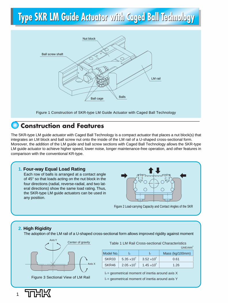
Figure 2 Load-carrying Capacity and Contact Angles of the SKR
Type SKR LM Guide Actuator with Caged Ball Technology Type SKR LM Guide Actuator with Caged Ball Technology
1
Figure 1 Construction of SKR-type LM Guide Actuator with Caged Ball Technology
The SKR-type LM guide actuator with Caged Ball Technology is a compact actuator that places a nut block(s) thatintegrates an LM block and ball screw nut onto the inside of the LM rail of a U-shaped cross-sectional form.Moreover, the addition of the LM guide and ball screw sections with Caged Ball Technology allows the SKR-typeLM guide actuator to achieve higher speed, lower noise, longer maintenance-free operation, and other features incomparison with the conventional KR-type.
Construction and Features
1. Four-way Equal Load RatingEach row of balls is arranged at a contact angleof 45° so that loads acting on the nut block in thefour directions (radial, reverse-radial, and two lat-eral directions) show the same load rating. Thus,the SKR-type LM guide actuators can be used inany position.
2. High RigidityThe adoption of the LM rail of a U-shaped cross-sectional form allows improved rigidity against moment
Center of gravityAxis Y
Axis X
Figure 3 Sectional View of LM Rail
Model No.
SKR33
SKR46
5.35 ×10⁴
2.05 ×10⁵
3.52 ×10⁵
1.45 ×10⁶
0.61
1.26
lX lY Mass (kg/100mm)
Unit:mm4
Table 1 LM Rail Cross-sectional Characteristics
lX = geometrical moment of inertia around axis X
lY = geometrical moment of inertia around axis Y
Nut block
Ball screw shaft
Ball cage Balls
LM rail
2
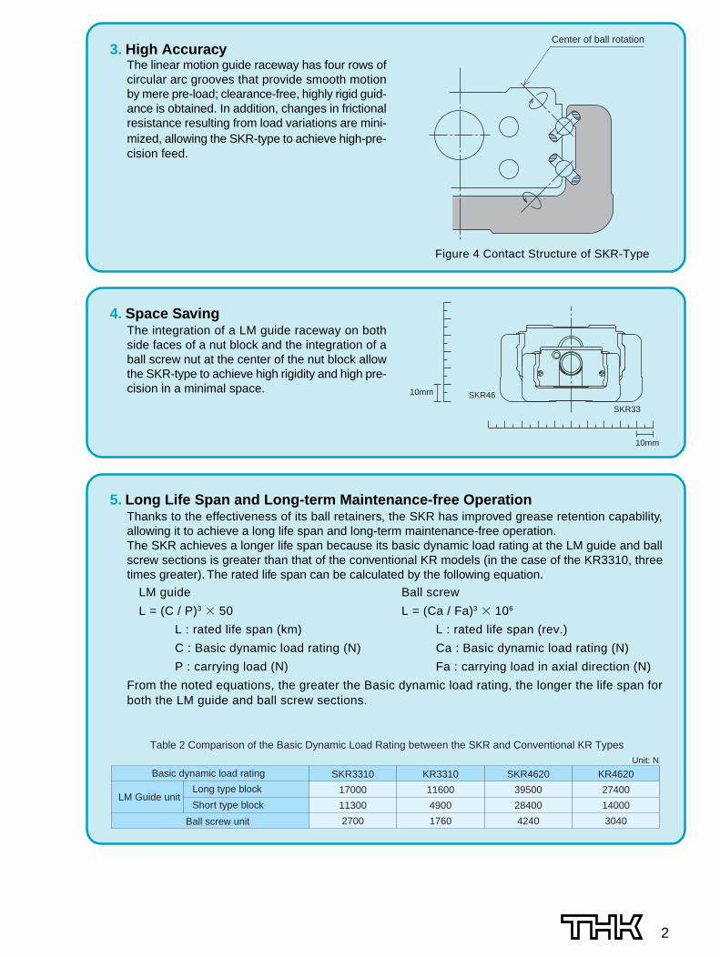
3. High AccuracyThe linear motion guide raceway has four rows ofcircular arc grooves that provide smooth motionby mere pre-load; clearance-free, highly rigid guid-ance is obtained. In addition, changes in frictionalresistance resulting from load variations are mini-mized, allowing the SKR-type to achieve high-pre-cision feed.
Center of ball rotation
Figure 4 Contact Structure of SKR-Type
4. Space SavingThe integration of a LM guide raceway on bothside faces of a nut block and the integration of aball screw nut at the center of the nut block allowthe SKR-type to achieve high rigidity and high pre-cision in a minimal space.
SKR3310
17000
11300
2700
KR4620
27400
14000
3040
SKR4620
39500
28400
4240
KR3310
11600
4900
1760
Table 2 Comparison of the Basic Dynamic Load Rating between the SKR and Conventional KR TypesUnit: N
Basic dynamic load rating
LM Guide unitLong type block
Short type block
Ball screw unit
10mm
10mm
SKR33
SKR46
5. Long Life Span and Long-term Maintenance-free OperationThanks to the effectiveness of its ball retainers, the SKR has improved grease retention capability,allowing it to achieve a long life span and long-term maintenance-free operation.The SKR achieves a longer life span because its basic dynamic load rating at the LM guide and ballscrew sections is greater than that of the conventional KR models (in the case of the KR3310, threetimes greater). The rated life span can be calculated by the following equation.
LM guide Ball screw
L = (C / P)3 � 50 L = (Ca / Fa)3 � 106
L : rated life span (km) L : rated life span (rev.)
C : Basic dynamic load rating (N) Ca : Basic dynamic load rating (N)
P : carrying load (N) Fa : carrying load in axial direction (N)
From the noted equations, the greater the Basic dynamic load rating, the longer the life span forboth the LM guide and ball screw sections.
3
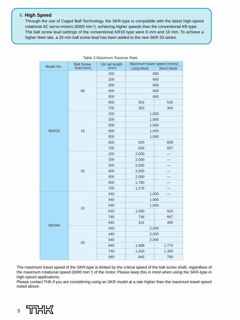
6. High SpeedThrough the use of Caged Ball Technology, the SKR-type is compatible with the latest high-speedrotational AC servo-motors (6000 min-1), achieving higher speeds than the conventional KR-type.The ball screw lead settings of the conventional KR33 type were 6 mm and 10 mm. To achieve ahigher feed rate, a 20 mm ball screw lead has been added to the new SKR 33 series.
SKR33
SKR46
06
10
20
10
20
150
200
300
400
500
600
700
150
200
300
400
500
600
700
150
200
300
400
500
600
700
340
440
540
640
740
940
340
440
540
640
740
940
552
393
920
656
2,000
2,000
2,000
2,000
2,000
1,780
1,276
1,000
736
431
1,988
1,433
845
600
600
600
600
600
1,000
1,000
1,000
1,000
1,000
1,000
1,000
1,000
2,000
2,000
2,000
530
364
839
607
—
—
—
—
—
—
—
—
914
667
400
1,774
1,300
784
Table 3 Maximum Traverse Rate
Model No.Ball Screw lead (mm)
LM rail length (mm)
Maximum travel speed (mm/s)Long block Short block
The maximum travel speed of the SKR-type is limited by the critical speed of the ball screw shaft, regardless ofthe maximum rotational speed (6000 min-1) of the motor. Please keep this in mind when using the SKR-type inhigh-speed applications.Please contact THK if you are considering using an SKR model at a rate higher than the maximum travel speednoted above.
4
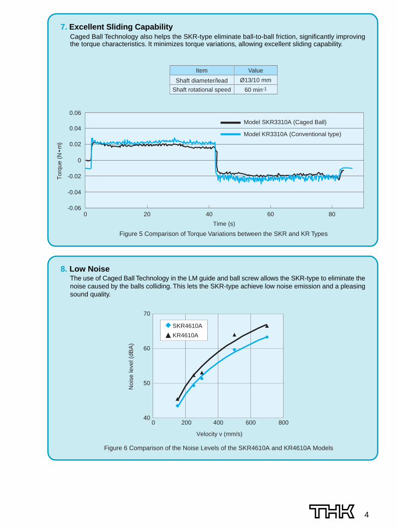
7. Excellent Sliding CapabilityCaged Ball Technology also helps the SKR-type eliminate ball-to-ball friction, significantly improvingthe torque characteristics. It minimizes torque variations, allowing excellent sliding capability.
0 20 40 60 80
0.06
0.04
0.02
0
-0.02
-0.04
-0.06
60 min-1
Item Value
Shaft diameter/lead Ø13/10 mm
Shaft rotational speed
Figure 5 Comparison of Torque Variations between the SKR and KR Types
Time (s)
Tor
que
(N •
m)
Model SKR3310A (Caged Ball)
Model KR3310A (Conventional type)
8. Low NoiseThe use of Caged Ball Technology in the LM guide and ball screw allows the SKR-type to eliminate thenoise caused by the balls colliding. This lets the SKR-type achieve low noise emission and a pleasingsound quality.
SKR4610A
KR4610A
70
60
50
400 200 400 600 800
Noi
se le
vel (
dBA
)
Velocity v (mm/s)
Figure 6 Comparison of the Noise Levels of the SKR4610A and KR4610A Models

This is the typical SKR model.
This is the model in which two nut blocks of the SKR-Amodel are provided to achieve higher rigidity, higher loadcapacity, and higher precision.
This is the model in which the full length of the SKR-Amodel nut block is shortened to have a longer stroke.Note that the SKR3320 model has no short type block.
This is the model in which two SKR-C model nut blocksare provided. By placing two blocks, it achieves high ri-gidity within the application limits.Note that the SKR3320 model has no short type block.
5
Models
SKR-A
SKR-B
SKR-C
SKR-D

● Load RatingThe SKR-type LM guide actuators with Caged BallTechnology consist of the LM guide, ball screw,and support bearing. Table 4 shows the load rat-ing.
6
Load Rating and Static Permissible Moment in Each Direction
• LM guide section unitThe SKR-type can carry loads in all directions, i.e., the radial, reverse-radial, and two lateral directions. Thebasic load rating is the same in these four directions and their values are shown in Table 4.
• Ball screw section unitThe SKR-type can carry loads in the axial direction since it incorporates a ball screw nut in the nut block. Thebasic load rating value is shown in Table 4.
• Support bearing unitThe SKR-type can carry loads in the axial direction since it incorporates an angular bearing in housing A. Thebasic load rating value is shown in Table 4.
● Equivalent Load (LM Guide Unit)When loads are simultaneously applied to the SKR-type's LM guide in all directions, the equivalent load isobtained by the following equation.P
E = P
R (P
L) + P
T
PE
: equivalent load (N)In the radial directionIn the reverse-radial directionIn the lateral directions
PR
: radial load (N)P
L: reverse-radial load (N)
PT
: load in the lateral directions (N)
SKR33
17000
11300
20400
11500
0 to –0.004
–0.004 to –0.012
13
6 10 20
10.8
13.5
4400 2700 2620
6290 3780 3770
6250
2700
SKR46
39500
28400
45900
28700
0 to –0.006
–0.006 to –0.016
15
10 20
12.5
15.75
4350 4240
6990 7040
6700
3330
Table 4 Load rating
Model
LM Guide
Basic dynamic load rating C (N)
Long nut block types A, B
Short nut block types C, D
Long nut block types A, B
Short nut block types C, DBasic static load rating C0 (N)
Radial clearance (mm) Normal grade, high accuracy grade
Precision quality grade
Ball Screw
Screw shaft outer diameter (mm)
Lead (mm)
Thread minor diameter (mm)
Ball center-to-center diameter (mm)
Basic dynamic load rating Ca (N)
Basic static load rating C0a (N)
Basic dynamic load rating Ca (N)
Static permissible load P0a (N)Support Bearing
Notes: • The load rating of the LM guide is the load rating per nut block.
• Model SKR3320 has no short type block.
PT PT
PL PR
7
SKR33 - A
SKR33 - B
SKR33 - C
SKR33 - D
SKR46 - A
SKR46 - B
SKR46 - C
SKR46 - D
173
990
58
390
579
3240
236
1460
173
990
58
390
579
3240
236
1460
424
848
240
480
1390
2780
870
1740
MA MB MC
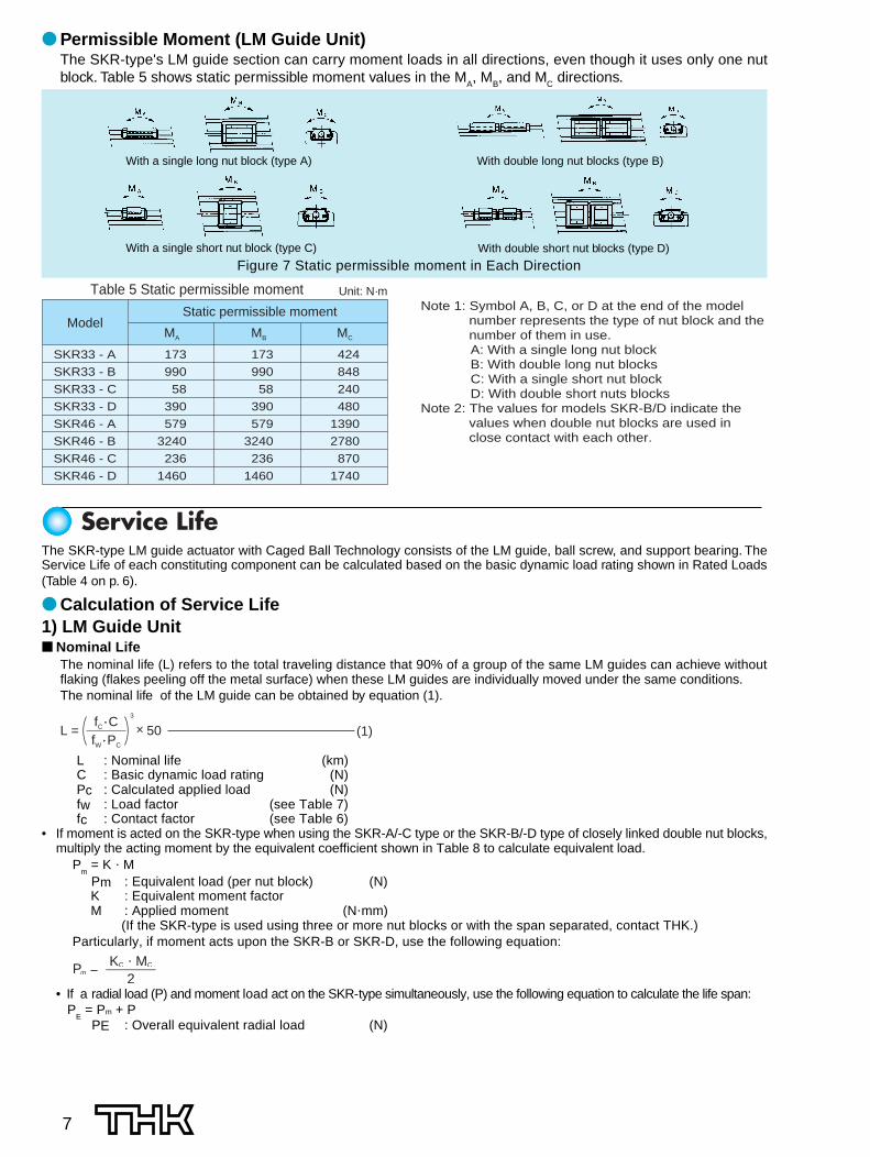
Table 5 Static permissible moment Unit: N·m
ModelStatic permissible moment Note 1: Symbol A, B, C, or D at the end of the model
number represents the type of nut block and the number of them in use.A: With a single long nut block B: With double long nut blocks C: With a single short nut block D: With double short nuts blocks
Note 2: The values for models SKR-B/D indicate the values when double nut blocks are used in close contact with each other.
● Permissible Moment (LM Guide Unit)The SKR-type's LM guide section can carry moment loads in all directions, even though it uses only one nutblock. Table 5 shows static permissible moment values in the M
A, M
B, and M
C directions.
Figure 7 Static permissible moment in Each Direction
The SKR-type LM guide actuator with Caged Ball Technology consists of the LM guide, ball screw, and support bearing. TheService Life of each constituting component can be calculated based on the basic dynamic load rating shown in Rated Loads(Table 4 on p. 6).
● Calculation of Service Life1) LM Guide Unit■ Nominal Life
The nominal life (L) refers to the total traveling distance that 90% of a group of the same LM guides can achieve withoutflaking (flakes peeling off the metal surface) when these LM guides are individually moved under the same conditions.The nominal life of the LM guide can be obtained by equation (1).
(1)L = 3
× 50fC
• CfW
• PC
L : Nominal life (km)C : Basic dynamic load rating (N)Pc : Calculated applied load (N)fw : Load factor (see Table 7)fc : Contact factor (see Table 6)
• If moment is acted on the SKR-type when using the SKR-A/-C type or the SKR-B/-D type of closely linked double nut blocks,multiply the acting moment by the equivalent coefficient shown in Table 8 to calculate equivalent load.
Pm = K � M
Pm : Equivalent load (per nut block) (N) K : Equivalent moment factor M : Applied moment (N�mm) (If the SKR-type is used using three or more nut blocks or with the span separated, contact THK.)Particularly, if moment acts upon the SKR-B or SKR-D, use the following equation:
PmPP = KC � MC
2• If a radial load (P) and moment load act on the SKR-type simultaneously, use the following equation to calculate the life span: P
E = Pm + P
PE : Overall equivalent radial load (N)
With a single long nut block (type A) With double long nut blocks (type B)
With a single short nut block (type C) With double short nut blocks (type D)
Service Life

8
2) Ball Screw Unit and Bearing Unit (Fixed side)■ Nominal Life
The nominal life (L) refers to the total number of revolutions that 90% of a group of the same Ball Screw(Bearings) can achieve without flaking when individually operated under the exact conditions.The nominal life of the Ball Screw Unit or bearing unit (fixed side) is calculated by equation (3).
(3)L = 3
× 106
Ca
fW • Fa
L : Nominal life (rev.)Ca : Basic dynamic load rating (N)Fa : Axial load (N)fw : Load factor (see Table 7)
■ Service Life TimeWhen the nominal life (L) is obtained, the life span can be calculated by equation (4) if the stroke length andreciprocations of the system per minute are defined.
Lh =L � �
2 � �S � n1 � 60(4)
Lh: Service life time (h)�s: Stroke length (mm)n1: Number of reciprocations per minute (min-1)�: Ball Screw lead (mm)
● fC: Contact FactorIf two nut blocks are used and closely linked together in theSKR-B or SKR-D type, multiply the basic load rating by thecontact factor shown in Table 6.
● fw: Load FactorTable 7 shows the load factor.
1.00.81
Table 6 Contact Factor (fC)
Block typeA/C TypeB/D Type
Contact Factor fC
Table 7 Load Factor (fW)Vibration or Impact Speed (V) fW
FaintWeak
MediumStrong
Very low:V � 0.25 m/sSlow:0.25 < V � 1.0 m/sMedium:1.0 < V � 2.0 m/s
High:V > 2.0 m/s
1.0 to 1.2
2.0 to 3.51.5 to 2.01.2 to 1.5
SKR33 - A
SKR33 - B
SKR33 - C
SKR33 - D
SKR46 - A
SKR46 - B
SKR46 - C
SKR46 - D
1.42×10⁻¹
2.47×10⁻²
2.39×10⁻¹
3.54×10⁻²
9.51×10⁻²
1.70×10⁻²
1.46×10⁻¹
2.36×10⁻²
1.42×10⁻¹
2.47×10⁻²
2.39×10⁻¹
3.54×10⁻²
9.51×10⁻²
1.70×10⁻²
1.46×10⁻¹
2.36×10⁻²
5.05×10⁻²
5.05×10⁻²
5.05×10⁻²
5.05×10⁻²
3.46×10⁻²
3.46×10⁻²
3.46×10⁻²
3.46×10⁻²
KA KB KC
Table 8 Moment Equivalent Factor (K)
Model No.
KA: moment equivalent factor in the MA direction KB: moment equivalent factor in the MB directionKC: moment equivalent factor in the MC directionNote: For the SKR-B and SKR-D types, the moment equivalent factor shows the value applied when two nut blocks are closely linked together.
● K: Moment Equivalent Factor (LM guide Unit)If a moment load is incurred, the load-carrying distribution on the LM guide increases locally. In this case, multiply themoment value with the moment equivalent factor shown in Table 8 to make the load calculation.K
A, K
B, and K
C show the moment equivalent loads in the M
A, M
B, and M
C directions respectively.
■ Service Life TimeWhen the nominal life (L) is obtained, the life span can be calculated by equation (2) if the stroke length andreciprocations of the system per minute are defined.
Lh =L � 106
2 � S � 1 � 60(2)
Lh : Service life time (h)�s : Stroke length (mm)n1 : Number of reciprocations per minute (min-1)
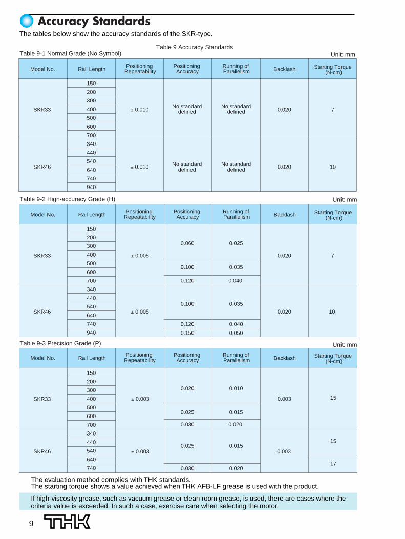
The tables below show the accuracy standards of the SKR-type.
9
150
200
300
400
500
600
700
340
440
540
640
740
940
150
200
300
400
500
600
700
340
440
540
640
740
940
SKR33
SKR46
± 0.010
± 0.010
0.020
0.020
7
10
15
15
17
± 0.003
± 0.003
0.003
0.003
0.060
0.100
0.120
0.100
0.120
0.150
0.025
0.035
0.040
0.035
0.040
0.050
7SKR33
SKR46
± 0.005
± 0.005
0.020
0.020 10
Table 9 Accuracy StandardsUnit: mmTable 9-1 Normal Grade (No Symbol)
Table 9-2 High-accuracy Grade (H)
Model No. Rail Length Positioning Repeatability
Positioning Accuracy
Running of Parallelism Backlash Starting Torque
(N-cm)
Unit: mm
Unit: mm
Model No. Rail Length Positioning Repeatability
Positioning Accuracy
Running of Parallelism Backlash Starting Torque
(N-cm)
150
200
300
400
500
600
700
340
440
540
640
740
0.020
0.025
0.030
0.025
0.030
0.010
0.015
0.020
0.015
0.020
SKR33
SKR46
Model No. Rail LengthPositioning
RepeatabilityPositioning Accuracy
Running of Parallelism Backlash Starting Torque
(N-cm)
No standarddefined
No standarddefined
No standarddefined
No standarddefined
Table 9-3 Precision Grade (P)
The evaluation method complies with THK standards.The starting torque shows a value achieved when THK AFB-LF grease is used with the product.
If high-viscosity grease, such as vacuum grease or clean room grease, is used, there are cases where thecriteria value is exceeded. In such a case, exercise care when selecting the motor.
Accuracy Standards
10
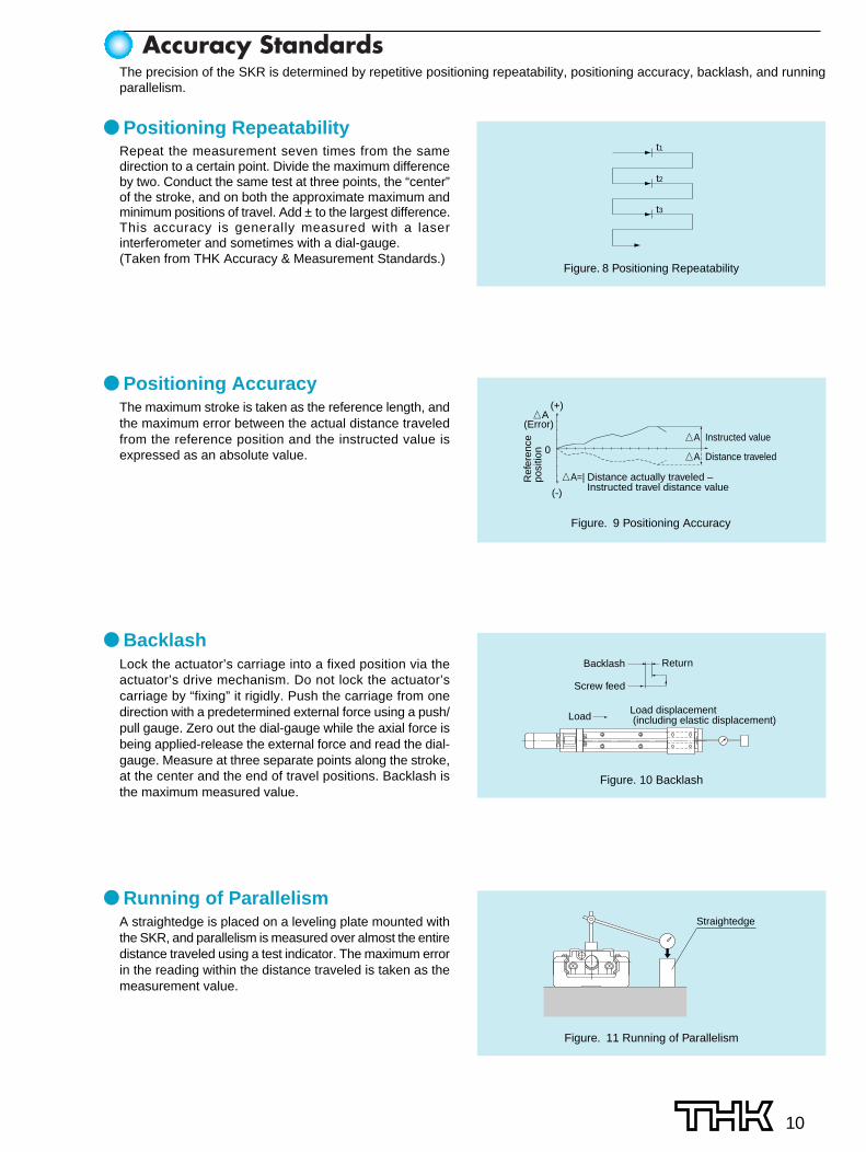
The precision of the SKR is determined by repetitive positioning repeatability, positioning accuracy, backlash, and runningparallelism.
● Positioning RepeatabilityRepeat the measurement seven times from the samedirection to a certain point. Divide the maximum differenceby two. Conduct the same test at three points, the “center”of the stroke, and on both the approximate maximum andminimum positions of travel. Add ± to the largest difference.This accuracy is generally measured with a laserinterferometer and sometimes with a dial-gauge.(Taken from THK Accuracy & Measurement Standards.)
● Positioning AccuracyThe maximum stroke is taken as the reference length, andthe maximum error between the actual distance traveledfrom the reference position and the instructed value isexpressed as an absolute value.
● BacklashLock the actuator’s carriage into a fixed position via theactuator’s drive mechanism. Do not lock the actuator’scarriage by “fixing” it rigidly. Push the carriage from onedirection with a predetermined external force using a push/pull gauge. Zero out the dial-gauge while the axial force isbeing applied-release the external force and read the dial-gauge. Measure at three separate points along the stroke,at the center and the end of travel positions. Backlash isthe maximum measured value.
● Running of ParallelismA straightedge is placed on a leveling plate mounted withthe SKR, and parallelism is measured over almost the entiredistance traveled using a test indicator. The maximum errorin the reading within the distance traveled is taken as themeasurement value.
Accuracy Standards
t1
t2
t3
Figure. 8 Positioning Repeatability
(+)
(-)
�A
�A=| Distance actually traveled – Instructed travel distance value
(Error)
0
Ref
eren
ce
posi
tion
�A Instructed value
�A Distance traveled
Figure. 9 Positioning Accuracy
Backlash Return
Screw feed
LoadLoad displacement (including elastic displacement)
Figure. 10 Backlash
Straightedge
Figure. 11 Running of Parallelism

H(mm)
n
150
200
300
400
500
600
700
220
270
370
470
570
670
770
55
105
205
305
405
505
605
129
229
329
429
529
1.7
2.1
2.8
3.5
4.2
5.0
5.7
3.1
3.8
4.5
5.3
6.0
25
50
50
100
50
100
50
G(mm)
25
50
50
50
50
50
50
F(mm)
100
100
200
200
200
200
200
2
2
3
4
5
6
7
n1
2
2
2
2
3
3
4
LM Rail Length (mm)
OverallLength
L1 (mm)
Available Stroke Range (mm)
Type A Type B Type A Type B
Overall main unit mass (kg)
59
11 30
23
8.5
5476
L1
8
11
F(n1-1) × FH (H)
3
9
ø30
H8
A 8h728
271016
G100
22
2
(G)
76 MIN
B
B
PC
D400.
742
.6 20.3
59.634
30°
30°43
.3
2.6
6030 15
3329
37.430
20
ø9.5 counter bore depth 5.4
LM rail length
4-M5 depth 6 2 × n1-M2.6 depth 4
2-M2 depth 5 2 × n-5.5 through hole
(Dimension with two nut blocks
in close contact)
(n-1)×100
�ø
ø
2-M3 depth 5 2-M4 through
2-M4 depth 8
A arrow view B - B cross section
The available stroke range of SKR33��B shows a value applicable when the product is used with two long type blocks closelylinked together.
11
1 Model number 2 Ball screw lead (mm) 3 Type of nut block 4 LM rail length (mm)5 Accuracy grade 6 With/without a motor 7 With/without a cover8 Sensor specifications (see page 19) 9 Type of housing – A: 010 Type of intermediate flange (see page 20) 11 Control number
SKR33 20 A + 700L P 0 - 0 0 0 01 2 3 5 9 10
11
6 8
How to Interpret the Model Number
4 7
SKR33 ��� Standard Type SKR33 �� A (with a Single Long Block)
SKR33 �� B (with Two Long Blocks)

59
11
8.5
28.550.5
L 1
11
23
8
HF
(H)(n1-1) × F
8h7
ø30
H8
28
3G
100
2
10
916
27 22
(G)
50.5
øø
B
B
A
(n-1) × 100
20.3
0.7
42.6
43.3
PC
D40
59.634
30°
30°
2.6
20
30
153060
29 33
37.4
LM rail length
2-M2 depth 5 2 × n1-M2.6 depth 4
2-M5 depth 6
2 × n-5.5 through holeø9.5 counter bore depth 5.4
(Dimension with two nut blocks
in close contact)
2-M3 depth 5 2-M4 through
2-M4 depth 8
A arrow view B - B cross section
150
200
300
400
500
600
700
220
270
370
470
570
670
770
80.5
130.5
230.5
330.5
430.5
530.5
630.5
30
80
180
280
380
480
580
1.6
2.0
2.7
3.4
4.1
4.8
5.5
1.8
2.1
2.8
3.6
4.3
5.0
5.7
25
50
50
100
50
100
50
25
50
50
50
50
50
50
100
100
200
200
200
200
200
2
2
3
4
5
6
7
2
2
2
2
3
3
4
H(mm)
nG(mm)
F(mm)
n1LM Rail Length (mm)
Overall Length
L1 (mm)
Available Stroke Range (mm)
Type C Type D Type C Type D
Overall main unit mass (kg)
The available stroke range of SKR33��D shows a value applicable when the product is used with two short type blocks closelylinked together.
12
SKR33 �� C (with a Single Short Block)
SKR33 �� D (with Two Short Blocks)
Normal gradeNo Symbol
High-accuracy gradeH
Precision gradeP
Not provided0
Provided (assembled at THK)1
Not provided0
Provided1
7
6
5
DescriptionSymbol
DescriptionSymbol
DescriptionSymbol
Accuracygrade
Provisionof Motor
Provisionof Cover

13
150
200
300
400
500
600
700
220
270
370
470
570
670
770
55
105
205
305
405
505
605
129
229
329
429
529
1.9
2.3
3.1
3.8
4.6
5.3
6.1
3.5
4.2
5.0
5.7
6.5
25
50
50
100
50
100
50
25
50
50
50
50
50
50
100
100
200
200
200
200
200
2
2
3
4
5
6
7
2
2
2
2
3
3
4
H(mm)
nG(mm)
F(mm)
n1LM Rail Length (mm)
OverallLength
L1 (mm)
Available Stroke Range (mm)
Type A Type B Type A Type B
Overall main unit mass (kg)
305476
5
B
B
A
31
0.7
PC
D40 60
1530
2.6
20
45.5
42.3
64
(0.8
5)
34
29
59.68674
4841
30°
30°
4-M5 depth 10
4-M2 depth 4(from the back side)
2-M4 through
2-M4 depth 8
A arrow view B - B cross section
2-M3 depth 5
The available stroke range of SKR33��B shows a value applicable when the product is used with two long type blocks closelylinked together.
1 Model number 2 Ball screw lead (mm) 3 Type of nut block 4 LM rail length (mm)5 Accuracy grade 6 With/without a motor 7 With/without a cover8 Sensor specifications (see page 19) 9 Type of housing – A: 010 Type of intermediate flange (see page 20) 11 Control number
SKR33 20 A + 700L P 0 - 0 0 0 01 2 3 5 9 10
11
6 8
How to Interpret the Model Number
4 7
SKR33 ��� (with the Cover) SKR33 �� A (with a Single Long Block)
SKR33 �� B (with Two Long Blocks)

14
5 21
28.550.5
B
B
30°
30°
42.3
45.5
0.7
PC
D40
30
60
86
20
34
59.6(0
.85)
64
74
41
15
2.6
29 31
48
4-M2 depth 4(from the back side)
2-M5 depth 10
A arrow view B - B cross section
2-M4 depth 8
2-M4 through2-M3 depth 5
150
200
300
400
500
600
700
220
270
370
470
570
670
770
80.5
130.5
230.5
330.5
430.5
530.5
630.5
30
80
180
280
380
480
580
1.8
2.2
2.9
3.7
4.4
5.2
5.9
2.0
2.3
3.1
3.8
4.6
5.3
6.1
25
50
50
100
50
100
50
25
50
50
50
50
50
50
100
100
200
200
200
200
200
2
2
3
4
5
6
7
2
2
2
2
3
3
4
H(mm)
nG(mm)
F(mm)
n1LM Rail Length (mm)
OverallLength
L1 (mm)
Available Stroke Range (mm)
Type C Type D Type C Type D
Overall main unit mass (kg)
The available stroke range of SKR33��D shows a value applicable when the product is used with two short type blocks closelylinked together.
SKR33 �� C (with a Single Short Block)
SKR33 �� D (with Two Short Blocks)
Normal gradeNo Symbol
High-accuracy gradeH
Precision gradeP
Not provided0
Provided (assembled at THK)1
Not provided0
Provided1
7
6
5
DescriptionSymbol
DescriptionSymbol
DescriptionSymbol
Accuracygrade
Provisionof Motor
Provisionof Cover
15
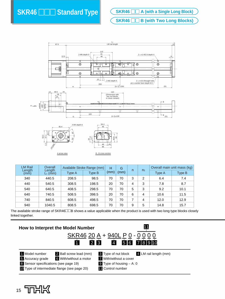
340
440
540
640
740
940
440.5
540.5
640.5
740.5
840.5
1040.5
208.5
308.5
408.5
508.5
608.5
808.5
98.5
198.5
298.5
398.5
498.5
698.5
6.4
7.8
9.2
10.6
12.0
14.8
7.4
8.7
10.1
11.5
12.9
15.7
70
20
70
20
70
70
70
70
70
70
70
70
3
4
5
6
7
9
2
3
3
4
4
5
H(mm)
nG(mm)
n1LM Rail Length (mm)
OverallLength
L1 (mm)
Available Stroke Range (mm)
Type A Type B Type A Type B
Overall main unit mass (kg)
87.5
12.5 46
10
L1
11081
9
13
H (H)(n1-1) ×200
46
200
ø42A
ø46
H8
ø10
h7
G100
2
48.5
18
14 2528
B(G)
B
(n-1)×100
110
57.1
PCD
601.2
26.3
85.4
30°
30°
5.7
29
46
8646 20
40.8
54.446
58.3
LM rail length
2 × n1-M2.6 depth 4
2-M2 depth 5 2 × n-6.6 through holeø11 counter bore depth 6.5
2-M6 depth 9
(Dimension with two nut blocks
in close contact)
4-M4 depth 8
A arrow view B - B cross section
The available stroke range of SKR46��B shows a value applicable when the product is used with two long type blocks closelylinked together.
1 Model number 2 Ball screw lead (mm) 3 Type of nut block 4 LM rail length (mm)5 Accuracy grade 6 With/without a motor 7 With/without a cover8 Sensor specifications (see page 19) 9 Type of housing – A: 010 Type of intermediate flange (see page 20) 11 Control number
SKR46 20 A + 940L P 0 - 0 0 0 01 2 3 5 9 10
11
6 8
How to Interpret the Model Number
4 7
SKR46 ��� Standard Type SKR46 �� A (with a Single Long Block)
SKR46 �� B (with Two Long Blocks)

16
10
87.5
4877
1L13
9
46
12.5
200(H)H (n1-1) × 200
A
3.5 G100
2
1428
18
48.5 25
B(G)
B
77
(n-1) × 100
ø46
H8
ø42
ø10
h7
46
85.4
PCD
60
1.2
58.3
26.3
57.1
40.8
4686
5.7
20
4654.4
30°
30°
29
A arrow view B - B cross section
4-M4 depth 8
LM rail length
2 × n1-M2.6 depth 42-M6 depth 9
2-M2 depth 5 2 × n-6.6 through holeø11 counter bore depth 6.5
(Dimension with two nut blocks
in close contact)
340
440
540
640
740
940
440.5
540.5
640.5
740.5
840.5
1040.5
241.5
341.5
441.5
541.5
641.5
841.5
164.5
264.5
364.5
464.5
564.5
764.5
6.1
7.5
8.9
10.3
11.7
14.5
6.7
8.1
9.5
10.8
12.2
15.0
70
20
70
20
70
70
70
70
70
70
70
70
3
4
5
6
7
9
2
3
3
4
4
5
H(mm)
nG(mm)
n1LM Rail Length (mm)
OverallLength
L1 (mm)
Available Stroke Range (mm)
Type A Type B Type A Type B
Overall main unit mass (kg)
The available stroke range of SKR46��D shows a value applicable when the product is used with two short type blocks closelylinked together.
KR15 ��� (With the Cover) SKR46 �� C (with a Single Short Block)
SKR46 �� D (with Two Short Blocks)
Normal gradeNo Symbol
High-accuracy gradeH
Precision gradeP
Not provided0
Provided (assembled at THK)1
Not provided0
Provided1
7
6
5
DescriptionSymbol
DescriptionSymbol
DescriptionSymbol
Accuracygrade
Provisionof Motor
Provisionof Cover

340
440
540
640
740
940
440.5
540.5
640.5
740.5
840.5
1040.5
208.5
308.5
408.5
508.5
608.5
808.5
98.5
198.5
298.5
398.5
498.5
698.5
7.1
8.6
10.0
11.5
13.0
16.0
8.3
9.8
11.3
12.7
14.2
17.2
70
20
70
20
70
70
70
70
70
70
70
70
3
4
5
6
7
9
2
3
3
4
4
5
H(mm)
nG(mm)
n1LM Rail Length (mm)
OverallLength
L1 (mm)
Available Stroke Range (mm)
Type A Type B Type A Type B
Overall main unit mass (kg)
112
5
4630
81110
B
B
40.8 43
204686
5.7
88100
5668
1.2
56.864
PC
D60
26
85.4
A
(1.8
)
30°
30°
4-M6 depth 12 4-M5 depth 10
4-M2.6 depth 5(from the back side)
A arrow view B - B cross section
4-M4 depth 8
The available stroke range of SKR46��B shows a value applicable when the product is used with two long type blocks closelylinked together.
17
1 Model number 2 Ball screw lead (mm) 3 Type of nut block 4 LM rail length (mm)5 Accuracy grade 6 With/without a motor 7 With/without a cover8 Sensor specifications (see page 19) 9 Type of housing – A: 010 Type of intermediate flange (see page 20) 11 Control number
SKR46 20 A + 940L P 0 - 0 0 0 01 2 3 5 9 10
11
6 8
How to Interpret the Model Number
4 7
SKR46 ��� (with the Cover) SKR46 �� A (with a Single Long Block)
SKR46 �� B (with Two Long Blocks)

35.55
48
77
B
B
A
5.7
30°
PC
D60 86
30°
1.2
64
56.8
26
46 20
85.4
100(1
.8)
88
112
40.8
68
56
43
A arrow view B - B cross section
4-M6 depth 12
4-M2.6 depth 5(from the back side)
4-M4 depth 8
340
440
540
640
740
940
440.5
540.5
640.5
740.5
840.5
1040.5
241.5
341.5
441.5
541.5
641.5
841.5
164.5
264.5
364.5
464.5
564.5
764.5
6.6
8.1
9.6
11.0
12.5
15.5
7.4
8.9
10.3
11.8
13.3
16.3
70
20
70
20
70
70
70
70
70
70
70
70
3
4
5
6
7
9
2
3
3
4
4
5
H(mm)
nG(mm)
n1LM Rail Length (mm)
OverallLength
L1 (mm)
Available Stroke Range (mm)
Type C Type D Type C Type D
Overall main unit mass (kg)
The available stroke range of SKR46��D shows a value applicable when the product is used with two short type blocks closelylinked together.
18
KR15 ��� (With the Cover) SKR46 �� C (with a Single Short Block)
SKR46 �� D (with Two Short Blocks)
Normal gradeNo Symbol
High-accuracy gradeH
Precision gradeP
Not provided0
Provided (assembled at THK)1
Not provided0
Provided1
7
6
5
DescriptionSymbol
DescriptionSymbol
DescriptionSymbol
Accuracygrade
Provisionof Motor
Provisionof Cover

The SKR is equipped with an end seal and side seal as standard for dust-proofing.
Side seal
End seal
19
Seals
SensorsProximity sensors and photosensors are available as options for the SKR33 and SKR46. When a customer speci-fies a model with a sensor, specially designed sensor rails and sensor dogs are supplied with the product.
● Sensor SpecificationsAccessory
–Mounting screwMounting screw/nut, detecting plate, sensor rail, mounting plate, connector (EE-1001)Mounting screw/nut, detecting plate, sensor rail, fixture (MS-GL12)Mounting screw/nut, detecting plate, sensor rail, fixture (MS-GXL12)Mounting screw/nut, detecting plate, sensor rail, mounting plate, connector (EE-1001)
Mounting screw/nut, detecting plate, sensor rail
Mounting screw/nut, detecting plate, sensor rail
Mounting screw/nut, detecting plate, sensor rail
Mounting screw/nut, detecting plate, sensor rail, fixture (MS-GXL12)
Mounting screw/nut, detecting plate, sensor rail
Mounting screw/nut, detecting plate, sensor rail
Mounting screw/nut, detecting plate, sensor rail, fixture (MS-GXL12)
Mounting screw/nut, detecting plate, sensor rail
Mounting screw/nut, detecting plate, sensor rail, fixture (MS-GXL12)
Type ––
EE-SX671 (OMRON) GL-12F (SUNX) GXL-N12F (SUNX)
EE-SX674 (OMRON)
APM-D3A1-001(YAMATAKE)
GL-N12F (SUNX)
GL-N12FB (SUNX)
GXL-N12FB (SUNX)
APM-D3B1-003(YAMATAKE)
GL-N12F (1 unit), GL-N12FB (2 units)
GXL-N12F (1 unit),GXL-N12FB (2 units)
APM-D3A1-001 (1 unit), APM-D3B1-003 (2 units)
GXL-N12F-P (1 unit),GXL-N12FB-P (2 units)
DescriptionNone With sensor rail
3 photosensors
3 proximity sensors Normally OPEN3 proximity sensors Normally OPEN
3 photosensors
3 proximity sensors Normally OPEN3 proximity sensors Normally OPEN3 proximity sensors Normally CLOSED3 proximity sensors Normally CLOSED3 proximity sensors Normally CLOSEDProximity sensor Normally OPEN (1), Normally CLOSED (2)Proximity sensor Normally OPEN (1), Normally CLOSED (2)Proximity sensor Normally OPEN (1), Normally CLOSED (2)Proximity sensor Normally OPEN (1), Normally CLOSED (2) (PNP OUTPUT)
Symbol01
2
4
5
6
7
8
9
A
B
C
D
E
F
20
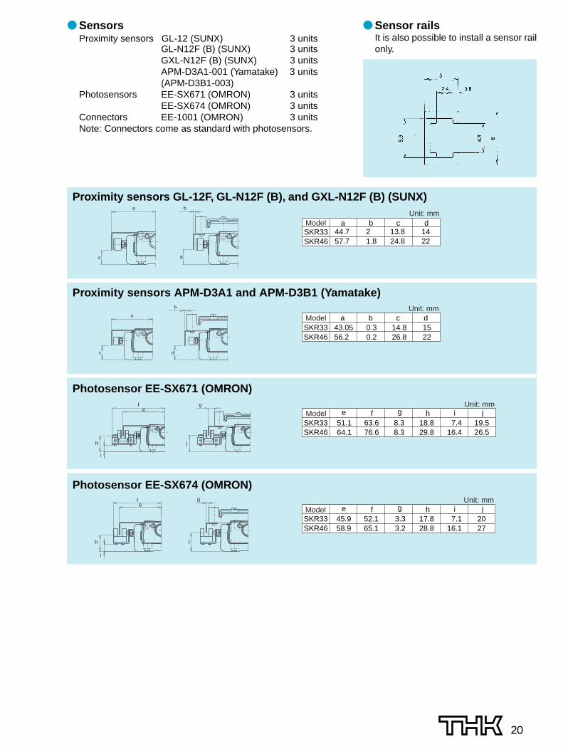
● Sensor railsIt is also possible to install a sensor railonly.
● SensorsProximity sensors GL-12 (SUNX) 3 units
GL-N12F (B) (SUNX) 3 unitsGXL-N12F (B) (SUNX) 3 unitsAPM-D3A1-001 (Yamatake) 3 units(APM-D3B1-003)
Photosensors EE-SX671 (OMRON) 3 unitsEE-SX674 (OMRON) 3 units
Connectors EE-1001 (OMRON) 3 unitsNote: Connectors come as standard with photosensors.
d
b
c
a
Proximity sensors GL-12F, GL-N12F (B), and GXL-N12F (B) (SUNX)
SKR33SKR46
44.757.7
2 1.8
13.824.8
1422
a b c dUnit: mm
Model
d
b
c
a
Proximity sensors APM-D3A1 and APM-D3B1 (Yamatake)
SKR33SKR46
43.0556.2
0.30.2
14.826.8
1522
a b c dUnit: mm
Model
j
g
i
h
ef
Photosensor EE-SX671 (OMRON)
SKR33SKR46
51.164.1
63.676.6
8.38.3
18.829.8
7.416.4
19.526.5
e f g h i jUnit: mm
Model
j
g
h
i
ef
Photosensor EE-SX674 (OMRON)
e f g h i jSKR33SKR46
45.958.9
52.165.1
3.33.2
17.828.8
7.116.1
2027
Unit: mmModel

21
● Applicable Motors and Applicable Intermediate FlangesThe SKR-type is provided with intermediate flanges so that a variety of motors can be installed. The table belowshows the control number of the intermediate flanges meeting the applicable motors on a model number basis.At the time of order, specify the intermediate flange control number.
Table11 Table of Motors Used and Corresponding Motor Brackets
Note1) The symbols in the table each indicate the last two digits of an administration number.Note2) For the coupling for mounting a motor in the table, contact THK.
Motor model No. Flange angle SKR33 SKR46
Ser
vom
otor
Yas
kaw
a E
lect
ric
∑-2
SGMAH-A3 (30W) 0H 0FSGMAH-A5 (50W) 0H 0FSGMAH-01 (100W) 0H 0FSGMPH-01 (100W) – 04SGMAH-02 (200W) – 04SGMAH-04 (400W) – 04
Mits
ubis
hi E
lect
ric
ME
LSE
RV
O
J2 S
uper
HC-MFS 053 (50W) 0FHC-KFS 053 (50W) 0FHC-MFS 13 (100W) 0FHC-KFS 13 (100W) 0H
0H0H0H
0FHC-MFS 23 (200W) – 04HC-KFS 23 (200W) – 04HC-MFS 43 (400W) – 04HC-KFS 43 (400W) – 04
Mat
sush
ita E
lect
ric
MIN
AS
A
MSMA 3A (30W) 0K0K
0GMSMA 5A (50W) 0GMSMA 01 (100W) 0K 0GMQMA 01 (100W) – 03MSMA 02 (200W) – 03MSMA 04 (400W) – 03
SAN
YO E
lect
ric
SAN
MO
TIO
N Q
1 Q1AA04003D (30W) 0H0H
0FQ1AA04005D (50W) 0FQ1AA04010D (100W) 0H 0FQ1AA06020D (200W) – 04Q1AA06040D (400W) – 04
OM
RO
N
OM
NU
C W
R88M-W03030 (30W) 0H0H
0FR88M-W05030 (50W) 0FR88M-W10030 (100W) 0H 0FR88M-W20030 (200W) – 04R88M-W40030 (400W) – 04
Fan
uc
βis
ser
ies
β0.2/5000is (50W) 0H 0F β0.3/5000is (100W) 0H 0F β0.4/5000is (125W) – 04 β0.5/5000is (200W) – 04 β1/5000is (400W) – 04
Ste
ppin
g m
otor
Orie
ntal
Mot
or αS
tep AS 46, ASC46 0I –
AS 6� , ASC66 0G 01
5 ph
ase
RK RK54� 0I –
RK56� 0G 01
2 ph
ase
UM
K UMK24� 0I –UMK26� 0F –
CS
K CSK24� 0I –CSK26�
�40
�60
�40
�60
�38
�60
�40
�60
�40
�60
�40
�60
�42�60�42�60�42
�56.4�42
�56.4 0F –
Intermediate Flanges

SKR330B0H0K0203040A0F0G
54 × 5442 × 4042 × 3862 × 6062 × 6062 × 6076 × 7662 × 5362 × 53
604645607070904645
503030505050703030
28282842424242
3 3 3.53.53.54 3.5
101010101010121010
M4M4M3M4M4M5M5M4M3
SKR46
G4
6
HFEDCB A × A’Control number
A
4 - G
45°
45°
A’ øC øD
H
E
F
PC
DB
Housing A
LM rail
22
SKR33
SKR46
0F0G01
56.4 × 56.460 × 6062 × 60
47.1450 50
38.136 36
2828
22
101010
M4M4M4
G5.27
HFEDCB A × A’Control number
SKR33 0I 42 × 42 31 22 7 3.5 6 4ZYXFEDCB A × A’Control number
A
B
øD
E
F4 - G
A’ øC
Housing A
LM rail
H
A E
F
B øDA’ øC
Housing A
LM rail
4 - X through holeøY counter bore depth Z (from the back side)
H
Dimensions of the Intermediate Flanges

HEAD OFFICE 3-11-6, NISHI-GOTANDA, SHINAGAWA-KU, TOKYO 141-8503 JAPAN INTERNATIONAL SALES DEPARTMENT PHONE:+81-3-5434-0351 FAX:+81-3-5434-0353
CHINATHK (CHINA) CO.,LTD.
TAIWANTHK TAIWAN CO.,LTD.
TAIPEI HEAD OFFICEPhone:+886-2-2888-3818TAICHUNG OFFICEPhone:+886-4-2359-1505 TAINAN OFFICEPhone:+886-6-289-7668
KOREASEOUL REPRESENTATIVE OFFICE
Phone:+82-2-3468-4351SINGAPORETHK LM SYSTEM Pte. Ltd.
NORTH AMERICATHK America,Inc.
HEADQUARTERSPhone:+1-847-310-1111 Fax:+1-847-310-1271CHICAGO OFFICEPhone:+1-847-310-1111 Fax:+1-847-310-1182NEW YORK OFFICEPhone:+1-845-369-4035 Fax:+1-845-369-4909ATLANTA OFFICEPhone:+1-770-840-7990 Fax:+1-770-840-7897LOS ANGELES OFFICEPhone:+1-949-955-3145 Fax:+1-949-955-3149SAN FRANCISCO OFFICEPhone:+1-925-455-8948 Fax:+1-925-455-8965BOSTON OFFICEPhone:+1-781-575-1151 Fax:+1-781-575-9295DETROIT OFFICEPhone:+1-248-858-9330 Fax:+1-248-858-9455TORONTO OFFICEPhone:+1-905-820-7800 Fax:+1-905-820-7811
SOUTH AMERICATHK Brasil LTDA
Phone:+55-11-3767-0100 Fax:+55-11-3767-0101EUROPETHK GmbH
TURKEY OFFICEPhone:+90-216-362-4050 Fax:+90-216-569-7150
DÜSSELDORF OFFICEPhone:+49-2102-7425-0 Fax:+49-2102-7425-299FRANKFURT OFFICEPhone:+49-2102-7425-650 Fax:+49-2102-7425-699STUTTGART OFFICEPhone:+49-7150-9199-0 Fax:+49-7150-9199-888MÜNCHEN OFFICEPhone:+49-8937-0616-0 Fax:+49-8937-0616-26U.K. OFFICEPhone:+44-1908-30-3050 Fax:+44-1908-30-3070ITALY MILANO OFFICEPhone:+39-039-284-2079 Fax:+39-039-284-2527ITALY BOLOGNA OFFICEPhone:+39-051-641-2211 Fax:+39-051-641-2230SWEDEN OFFICEPhone:+46-8-445-7630 Fax:+46-8-445-7639 AUSTRIA OFFICEPhone:+43-7229-51400 Fax:+43-7229-51400-79SPAIN OFFICEPhone:+34-93-652-5740 Fax:+34-93-652-5746
THK France S.A.S.Phone:+33-4-3749-1400 Fax:+33-4-3749-1401
EUROPEAN HEADQUARTERSPhone:+49-2102-7425-0 Fax:+49-2102-7425-217
SHANGHAI OFFICEPhone:+86-21-6219-3000 Fax:+86-21-6219-9890BEIJING OFFICEPhone:+86-10-8441-7277 Fax:+86-10-6590-3557CHENGDU OFFICEPhone:+86-28-8526-8025 Fax:+86-28-8525-6357GUANGZHOU OFFICEPhone:+86-20-8333-9770 Fax:+86-20-8333-9726
HEADQUARTERSPhone:+86-411-8733-7111 Fax:+86-411-8733-7000
THK (SHANGHAI) CO.,LTD.Phone:+86-21-6275-5280 Fax:+86-21-6219-9890
Fax:+886-2-2888-3819
Fax:+886-4-2359-1506
Fax:+886-6-289-7669
Fax:+82-2-3468-4353
Fax:+65-6884-5550INDIABANGALORE REPRESENTATIVE OFFICE
Phone:+91-80-2330-1524
Phone:+65-6884-5500
Fax:+91-80-2314-8226
Global site : http://www.thk.com/
©THK CO., LTD. 20071003 E4 Printed in Japan
LM-Guide Actuator SKR-type
All rights reserved.
Precautions on Use
● “LM Guide”, “Caged Ball” and “ ” are the registered trademarks of THK CO., LTD.● There may be differences between products appearing in photographs and the actual product.● The appearance, specifications, and other information are subject to change without prior notice to improve
reliability, function, etc. When deciding to adopt the product, contact us beforehand.● We have exercised great care in preparing this catalog, but it is still possible that there are misspellings, omissions
of letters, etc. THK assumes no responsibility or liability for damage resulting from such errors possibly containedherein.
● We employ the basic policy of observing the Foreign Exchange and Foreign Trade Control Law of Japan withregard to the export of our products/technologies or sales for export. For export of our products as discretecomponents, consult THK beforehand.
● Handling• Exercise care when handling the product. Dropping or tapping it may result in breakage.• Do not disassemble the product unless it is unavoidable. Disassembling the product unnecessarily may result
in the entry of foreign matter or cause accuracy degradation.• Operating the product exceeding the permissible revolution speed may lead to part breakage or accidents.
The operating revolution speed should be limited to the range specified by THK.
● Operating temperature range• The service temperature range of this product is 0 to 40°C (no freezing or condensation). If you consider using
this product outside the service temperature range, contact THK.
● Lubrication• To deliver the full extent of SKR-type functions, lubrication is essential. Use of the product without lubrication
may result in increased abrasion at the rolling section or shorter life.• Do not mix and use lubricants with different properties.• The greasing intervals differ with the operating conditions. It is recommended that the greasing intervals be
determined at the initial inspection.• If the product is used in locations constantly exposed to vibration or in special environments such as clean rooms,
vacuums, low temperatures, or high temperatures, there are cases where ordinary greases cannot be used. In suchcases, contact THK.
● Use and Lubrication in Special Environments• If locations are constantly exposed to vibration or in special environments such as clean rooms, vacuums, low
temperatures, or high temperatures, consult THK.
● Safety precautions• If the product is operating or in the ready state, never touch a moving part. In addition, do not enter the operating
area of the actuator.• If two or more people are involved in the operation, confirm the procedures such as a sequence, signs and anomalies
in advance, and appoint another person for monitoring the operation.