new orders - home - global science journals · new orders in search of a new point-block diagram...
TRANSCRIPT
New Orders In search of a new point-block diagram for Hong Kong
Olivier Ottevaere
Department of Architecture
The University of Hong Kong
Abstract— A series of alternative structures for housing are proposed through a design-research prototyping process. Nine proto-structures are developed through the conception and realization of columns cast in concrete. The series explores specific structural principles at 1to1 scale, which are further architecturally tested as speculative towers for urban living at 1to100 scale. At 1 to 1 scale, concrete as process rather than just concrete as material sets the main methodology for the design-research. Trial and error experiments, closely related to the properties of the material (liquid to solid formation), seek to put forward new techniques of formwork design and construction procedures that are more flexible and more sustainable than past and current systems. Design analysis, informed by the work of the early ‘structural rationalists’ (F. Candela, P.L. Nervi, H. Isler, R. Maillard, E. Dieste, et al.), considers the transformation of structural languages in an attempt to revive an architecture for vertical living (point-block).
Keywords- Point-block towers, reinforced concrete,
formwork design, structural system, Housing speculations
I. INTRODUCTION
A. Historical Background
The modernist search for concrete-based new models for
living, fuelled by an urgent need for cheap housing after the
world war destruction, was devised in Western Europe in the
form of a cast-in-place skeleton frame. In the late 19th
century, this flexible column-slab system was first patented
and distributed by the ‘Hennebique’ enterprise, supported
globally by his licensed agents and concessionary contractors
[1]. His focus on reinforced concrete structure prompted the
initial schism between architectural design and technical
construction.
In 1914, Le Corbusier generalized a two-storey column slab
structure, known as the Dom-ino protocol (domus-innovation).
Its promise was social; to support individualization of living
spaces by internally liberating the plan of a building from its
structural imperatives (Free Plan).
This mass-produced and standardized construction method
provided its future inhabitants with a plain and low-cost
framework to be further individualized based on means,
aspirations and identity. What the Dom-ino model essentially
offered, by highlighting the slab, was the idea of an empty
plan; a new ground, released from the literal one [2]. This
quickly projected the possibility of envisioning a multiplicity
of ‘free’ grounds (as slabs) whose sequence of spatial
organizations would not need to be identical anymore
(homogeneity vs. repetition of differences): A clear concept
that has struggled to this day to fulfill its early assignment.
On the contrary, the structural ideal largely continues to
overshadow its architectural benefits, caused by a
preoccupation for high efficiency, great economy of means
and for the small labor skills it demands (DIY).
A century later, this now ubiquitous structural system has
largely achieved the reverse: mainly creating an order
characterized by homogeneity based on the repetition of the
same living units across many building scales.
However, the advent of structural reinforced concrete
originated long before Le Corbusier’s 1914 icon.
Much needed experimentation had taken place over half a
century prior to any practical and theoretical formulations.
Architects and engineers were the last and least advocates of
the potential for this new hybrid (concrete and steel) and
continuous material. Many of the physical undertakings,
conducted around 1850, through successive trial and error
efforts at full scale, were just carried out by builders and
contractors (i.e. J. Monier, F. Coignet, J. Lambot, et al.) in
their backwards [3].
It was only after various inaugurations of proven patents (F.
Hennebique, R. Maillart, et al.) in international fairs that
architects, such as Auguste Perret (for whom Corbusier used
to be a young apprentice), started to sympathize with the
‘modern’ material.
In pursuit of greater structural and material honesty, A. Perret
and his brothers, not only dared to incorporate the skeleton
frame in their (self-) built projects, but highly contrasted it
against some of the more classical features dominating their
architecture. 1904 saw one of the first detachments between
(concrete) structure and infill in architecture, rationally
manifested in Perret’s rue Franklin apartment building in Paris
[4].
B. Hong Kong point-block
For some time now, the post-slab system has been more in full
service of the developer and contractor, seeking larger sale
margins, than of the architect, prioritizing perhaps more
Journal of Engineering Technology (JET) DOI: 10.5176/2251-3701_4.1.175Print ISSN: 2251-3701, E-periodical: 2251-371X ; Volume 4, Issue 1; 2016 pp. 72 - 80© The Author(s) 2016. This article is published with open access by the GSTF.
72 | Journal of Engineering Technology (JET) Vol.4 No.1, August 2016
DOI 10.7603/s40707-016-0011-8
spatial diversity and better living qualities. Hong Kong’s built
environment demonstrates vividly that assertion, where all
living cells within a building entity have each been normalized
at great heights, facilitated by a rudimentary cast in situ
concrete frame to which standard facades and curtain walls are
clipped on.
Housing complexes in this context have become condensed
agglomerates of sealed units around a single core, pruned for
individual living. The collective qualities that once
distinguished the early experiments of the Housing Authority
in Hong Kong have slowly been stripped off from buildings
and at best flattened to quasi-public podia [5]. The podium-
tower model, Hong Kong’s dominant living type, suggests
little possibility for community living, caused by a relentless
repetition of the same living cells within a built complex.
Indeed, integrated public spaces (i.e. courtyards, elevated
streets as extensions of living spaces), outdoor living at the
unit scale, shared functions, amenity spaces, public grounds
and urban connectors, all which stimulate social interaction in
housing, are nowadays scarce encounters in residential
projects in Hong Kong.
The proposed design-research aims to develop new structural
articulations for high-rises that are more agile in transiting
from one type of program to another within a complex. These
aim to provide residents with gradients of communal spaces
that reconcile (semi-) outdoor living issues in a sub-tropical
climate.
C. The Structural rationlists
If one considers concrete as process and not just concrete as
material, all that has been presented above, might appear not
so Modern, after all. Reminiscent of timber structures used in
construction previously, these ‘new’ reinforced concrete
systems do not capitalize enough on the properties of the
material; a liquid and continuous agent. For the most part, they
have more efficiently repeated formerly known structural
systems with a new material. Instead of being restricted to an
amalgam of predefined rigid elements (post, beam and slab,
more suitable for timber and steel), greater design investments
in formwork methods might greatly contribute to the quest for
new volumetric continuity and for different spatial
organizations, beyond efficiency and practicality. In this
respect, technology and innovation must be less concerned
with the material’s imperatives per-say but rather strive to emulate the range of discoveries that emerged from the early
empirical methods of concrete constructions.
Only after World War Two, non-conformists came to
reconsider the full potential that reinforced concrete suggested
at its origin. Sometimes called the structural (hyper)
rationalists, personalities like Torroja, Nervi, Candela, Isler,
Maillart, pushed to great effects the true premises of the
original material: a short lived liquid mass in space, in search
of new solid formations.
To address this, they placed a strong emphasis on
experimentation towards the development of formwork
design, supported by well-articulated geometries and methods
of construction that will liberate concrete again from an all too
safe and predicable approach (a ‘Non Safety Factor’
approach). Yet, the restored attitude towards structural
concrete did not just come without a high level of risk taking
and from time to time without failures.
While these structural mavericks took reinforced concrete to
the limit of what the new material could do both structurally
and spatially, their pioneering work responded, for the most
part, to lower building scales and to singular programs (i.e.
civic, cultural, religious); all but Housing.
The research revives the dialogue in the context of high
density Asian living. The dialogue is being pursued with new
technology in formwork design that breaks from the
homogenizing influence of concrete and from the monotony of
current systems.
II. METHODOLOGY
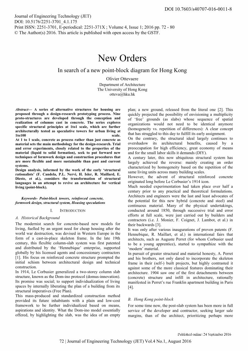
Figure 1. Concrete prototypes of column 1 to 7
Seven concrete prototypes are explained from conception to
realization. The methods described include literature review of
precedents, structural and environmental analysis, parametric
design, formwork fabrication and housing speculations.
At a time when much design and fabrication emphasis is
placed on surface definition, the presented methods instead
concentrate on the physical description of negative volumes,
for concrete casting. In some cases, projective geometries are
used to rationalize intricate solids into assemblies of 2d
templates, guiding an optimal 3d interpolation of the global
geometry for the making of the formworks.
73 | Journal of Engineering Technology (JET) Vol.4 No.1, August 2016
Olivier Ottevaere
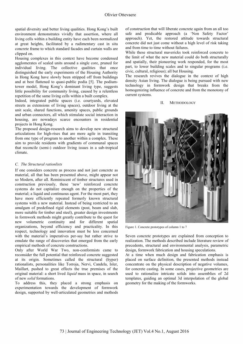
A. Column 1 (Shelling and Fluting)
Figure. 2a Figure. 2b
The architectural investigation for this prototype proposes a
sequence of semi-public outdoor spaces within the shaft of a
column through perforations while aiming for a high degree of
structural integrity. To achieve this, a structural knuckle made
of a maximum of air was conceived with minimum material
(Fig. 2a). Column 1 draws on the history of thin shell
structures, specifically by revisiting Felix Candela’s work on
Hyperbolic Paraboloid also known as Hypar. Warped surfaces,
efficiently described by a series of rotating lines (ruled
geometry) and in close proximity with its resulting formwork
procedure (lines materialized by straight timber elements),
serve as the principal spatial and structural element for the
void description [6].
Instead of considering saddle structures as single storey, the
prototype instigates their potential to stack up into a vertical
compound of interchanging vaults. 4 rotating hypars of varied
amplitudes interlock to describe 3 successive voids within a
vertical shaft (Fig. 2b). The first tested hypar composite
comprises of 87 percent of air and of 13 percent of structural
mass.
Following a series of incremental formwork design and
casting tests, a final 1to1 scale prototype was built to assess its
loading resistance. The concrete shaft consists of three parts; a
bottom support, the middle hypar composite of 12mm thick,
weighting 5kgs and a top loading element of 30kgs. The
ceiling planes of each of the saddle surfaces were structurally
amplified by protruded ribbed beams connecting the ruled
lines of the successive hypars. Those same lines were
extended out as flutes along the surface of the shaft in an
effort to accentuate the column’s vertical reading (Fig. 2c).
Figure 2c Figure 2d Figure 2e
Upon completion, the prototype was assessed to be properly
performing under dead load and deemed successful as initial
proof of concept. Further analyses through computational
simulations were conducted to evaluate more accurately the
stresses distribution from hypar to hypar under various loading
scenarios.
The fabrication of the formwork took into account the issue of
formwork decentering known in thin shell structures. This was
accounted for through a two-step casting process; by first
producing the 3 positive voids in rubber as part of the final
mould for the concrete hypar composite (Fig.2d, 2e). The
rubber plugs were used for their ductile property in
demoulding to prevent any concentration of stresses on the
shells.
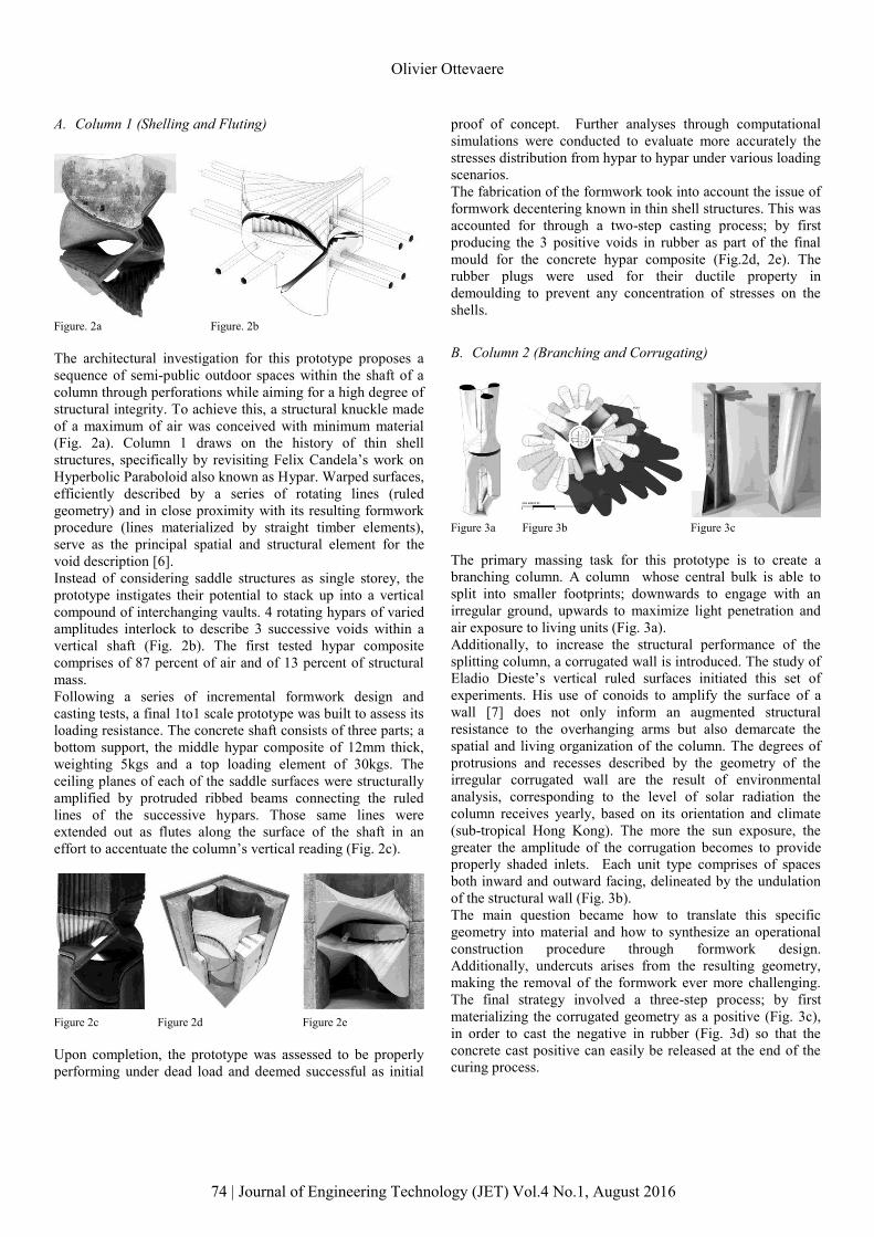
B. Column 2 (Branching and Corrugating)
Figure 3a Figure 3b Figure 3c
The primary massing task for this prototype is to create a
branching column. A column whose central bulk is able to
split into smaller footprints; downwards to engage with an
irregular ground, upwards to maximize light penetration and
air exposure to living units (Fig. 3a).
Additionally, to increase the structural performance of the
splitting column, a corrugated wall is introduced. The study of
Eladio Dieste’s vertical ruled surfaces initiated this set of
experiments. His use of conoids to amplify the surface of a
wall [7] does not only inform an augmented structural
resistance to the overhanging arms but also demarcate the
spatial and living organization of the column. The degrees of
protrusions and recesses described by the geometry of the
irregular corrugated wall are the result of environmental
analysis, corresponding to the level of solar radiation the
column receives yearly, based on its orientation and climate
(sub-tropical Hong Kong). The more the sun exposure, the
greater the amplitude of the corrugation becomes to provide
properly shaded inlets. Each unit type comprises of spaces
both inward and outward facing, delineated by the undulation
of the structural wall (Fig. 3b).
The main question became how to translate this specific
geometry into material and how to synthesize an operational
construction procedure through formwork design.
Additionally, undercuts arises from the resulting geometry,
making the removal of the formwork ever more challenging.
The final strategy involved a three-step process; by first
materializing the corrugated geometry as a positive (Fig. 3c),
in order to cast the negative in rubber (Fig. 3d) so that the
concrete cast positive can easily be released at the end of the
curing process.
74 | Journal of Engineering Technology (JET) Vol.4 No.1, August 2016
Olivier Ottevaere
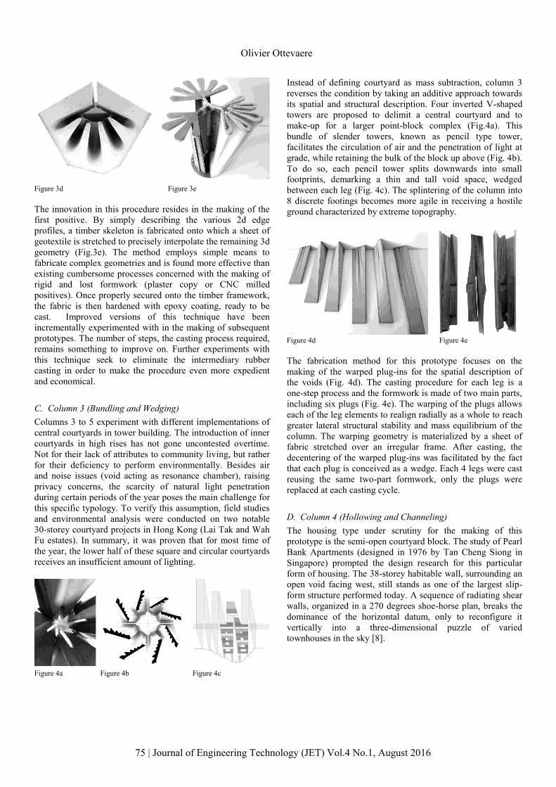
Figure 3d Figure 3e
The innovation in this procedure resides in the making of the
first positive. By simply describing the various 2d edge
profiles, a timber skeleton is fabricated onto which a sheet of
geotextile is stretched to precisely interpolate the remaining 3d
geometry (Fig.3e). The method employs simple means to
fabricate complex geometries and is found more effective than
existing cumbersome processes concerned with the making of
rigid and lost formwork (plaster copy or CNC milled
positives). Once properly secured onto the timber framework,
the fabric is then hardened with epoxy coating, ready to be
cast. Improved versions of this technique have been
incrementally experimented with in the making of subsequent
prototypes. The number of steps, the casting process required,
remains something to improve on. Further experiments with
this technique seek to eliminate the intermediary rubber
casting in order to make the procedure even more expedient
and economical.
C. Column 3 (Bundling and Wedging)
Columns 3 to 5 experiment with different implementations of
central courtyards in tower building. The introduction of inner
courtyards in high rises has not gone uncontested overtime.
Not for their lack of attributes to community living, but rather
for their deficiency to perform environmentally. Besides air
and noise issues (void acting as resonance chamber), raising
privacy concerns, the scarcity of natural light penetration
during certain periods of the year poses the main challenge for
this specific typology. To verify this assumption, field studies
and environmental analysis were conducted on two notable
30-storey courtyard projects in Hong Kong (Lai Tak and Wah
Fu estates). In summary, it was proven that for most time of
the year, the lower half of these square and circular courtyards
receives an insufficient amount of lighting.
Figure 4a Figure 4b Figure 4c
Instead of defining courtyard as mass subtraction, column 3
reverses the condition by taking an additive approach towards
its spatial and structural description. Four inverted V-shaped
towers are proposed to delimit a central courtyard and to
make-up for a larger point-block complex (Fig.4a). This
bundle of slender towers, known as pencil type tower,
facilitates the circulation of air and the penetration of light at
grade, while retaining the bulk of the block up above (Fig. 4b).
To do so, each pencil tower splits downwards into small
footprints, demarking a thin and tall void space, wedged
between each leg (Fig. 4c). The splintering of the column into
8 discrete footings becomes more agile in receiving a hostile
ground characterized by extreme topography.
Figure 4d Figure 4e
The fabrication method for this prototype focuses on the
making of the warped plug-ins for the spatial description of
the voids (Fig. 4d). The casting procedure for each leg is a
one-step process and the formwork is made of two main parts,
including six plugs (Fig. 4e). The warping of the plugs allows
each of the leg elements to realign radially as a whole to reach
greater lateral structural stability and mass equilibrium of the
column. The warping geometry is materialized by a sheet of
fabric stretched over an irregular frame. After casting, the
decentering of the warped plug-ins was facilitated by the fact
that each plug is conceived as a wedge. Each 4 legs were cast
reusing the same two-part formwork, only the plugs were
replaced at each casting cycle.
D. Column 4 (Hollowing and Channeling)
The housing type under scrutiny for the making of this
prototype is the semi-open courtyard block. The study of Pearl
Bank Apartments (designed in 1976 by Tan Cheng Siong in
Singapore) prompted the design research for this particular
form of housing. The 38-storey habitable wall, surrounding an
open void facing west, still stands as one of the largest slip-
form structure performed today. A sequence of radiating shear
walls, organized in a 270 degrees shoe-horse plan, breaks the
dominance of the horizontal datum, only to reconfigure it
vertically into a three-dimensional puzzle of varied
townhouses in the sky [8].
75 | Journal of Engineering Technology (JET) Vol.4 No.1, August 2016
Olivier Ottevaere
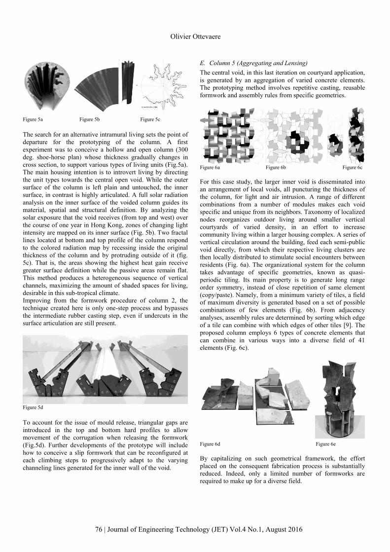
Figure 5a Figure 5b Figure 5c
The search for an alternative intramural living sets the point of
departure for the prototyping of the column. A first
experiment was to conceive a hollow and open column (300
deg. shoe-horse plan) whose thickness gradually changes in
cross section, to support various types of living units (Fig.5a).
The main housing intention is to introvert living by directing
the unit types towards the central open void. While the outer
surface of the column is left plain and untouched, the inner
surface, in contrast is highly articulated. A full solar radiation
analysis on the inner surface of the voided column guides its
material, spatial and structural definition. By analyzing the
solar exposure that the void receives (from top and west) over
the course of one year in Hong Kong, zones of changing light
intensity are mapped on its inner surface (Fig. 5b). Two fractal
lines located at bottom and top profile of the column respond
to the colored radiation map by recessing inside the original
thickness of the column and by protruding outside of it (fig.
5c). That is, the areas showing the highest heat gain receive
greater surface definition while the passive areas remain flat.
This method produces a heterogeneous sequence of vertical
channels, maximizing the amount of shaded spaces for living,
desirable in this sub-tropical climate.
Improving from the formwork procedure of column 2, the
technique created here is only one-step process and bypasses
the intermediate rubber casting step, even if undercuts in the
surface articulation are still present.
Figure 5d
To account for the issue of mould release, triangular gaps are
introduced in the top and bottom hard profiles to allow
movement of the corrugation when releasing the formwork
(Fig.5d). Further developments of the prototype will include
how to conceive a slip formwork that can be reconfigured at
each climbing steps to progressively adapt to the varying
channeling lines generated for the inner wall of the void.
E. Column 5 (Aggregating and Lensing)
The central void, in this last iteration on courtyard application,
is generated by an aggregation of varied concrete elements.
The prototyping method involves repetitive casting, reusable
formwork and assembly rules from specific geometries.
Figure 6a Figure 6b Figure 6c
For this case study, the larger inner void is disseminated into
an arrangement of local voids, all puncturing the thickness of
the column, for light and air intrusion. A range of different
combinations from a number of modules makes each void
specific and unique from its neighbors. Taxonomy of localized
nodes reorganizes outdoor living around smaller vertical
courtyards of varied density, in an effort to increase
community living within a larger housing complex. A series of
vertical circulation around the building, feed each semi-public
void directly, from which their respective living clusters are
then locally distributed to stimulate social encounters between
residents (Fig. 6a). The organizational system for the column
takes advantage of specific geometries, known as quasi-
periodic tiling. Its main property is to generate long range
order symmetry, instead of close repetition of same element
(copy/paste). Namely, from a minimum variety of tiles, a field
of maximum diversity is generated based on a set of possible
combinations of few elements (Fig. 6b). From adjacency
analyses, assembly rules are determined by sorting which edge
of a tile can combine with which edges of other tiles [9]. The
proposed column employs 6 types of concrete elements that
can combine in various ways into a diverse field of 41
elements (Fig. 6c).
Figure 6d Figure 6e
By capitalizing on such geometrical framework, the effort
placed on the consequent fabrication process is substantially
reduced. Indeed, only a limited number of formworks are
required to make up for a diverse field.
76 | Journal of Engineering Technology (JET) Vol.4 No.1, August 2016
Olivier Ottevaere
Mass-production and formwork reusability is the main focus
for the prototyping endeavor. Six formworks are devised as 8-
part moulds (1 top, 1 bottom and 4 sides) in the production of
the 3-dimensional modules. The CNC parts of the EPS mould
are made independent to ease the (re)assembly and
dismantling of the formwork at every pouring cycle (Fig. 6d).
Upon final assembly of the column prototype, it was
surprisingly found that the concrete modules were supporting
one another by gravity or simple friction between the tiles
‘edges without the need for extra bonding or mechanical
connections (Fig. 6e). To amplify the reading of the various
combinations of elements (ranging from 3 to 8 tiles) that
disclose each void, the tiles external surfaces are made
concave. Rather than placing emphasis on the concrete
elements per say, this process of lensing strengthen the
reading of the seams as the principal structural driver for the
prototype.
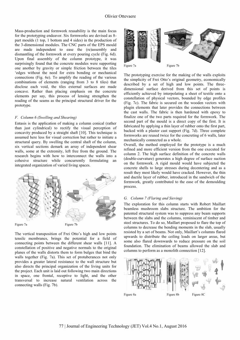
F. Column 6 (Swelling and Shearing)
Entasis is the application of making a column conical (rather
than just cylindrical) to rectify the visual perception of
concavity produced by a straight shaft [10]. This technique is
assumed here less for visual correction but rather to initiate a
structural query. By swelling the central shaft of the column,
six vertical sections demark an array of independent shear
walls, some at the extremity, left free from the ground. The
research begins with how to interconnect the walls into a
cohesive structure while concurrently formulating an
integrated organization of varied living spaces.
Figure 7a Figure 7b
The vertical transposition of Frei Otto’s high and low points
tensile membranes, brings the potential for a field of
connecting points between the different shear walls [11]. A
constellation of positive and negative normals to the original
planes of the walls distorts them to form bulges that bind the
walls together (Fig. 7a). This set of protuberances not only
provides a greater lateral resistance to the wall structure but
also directs the principal organization of the living units for
the project. Each unit is laid out following two main directions
in space, one frontal, receptive to light, and the other
transversal to increase natural ventilation across the
connecting walls (Fig. 7b).
Figure 7a Figure 7b
The prototyping exercise for the making of the walls exploits
the simplicity of Frei Otto’s original geometry, economically
described by a set of high and low points. The three-
dimensional surface derived from this set of points is
efficiently achieved by interpolating a sheet of textile onto a
constellation of physical vectors, bounded by edge profiles
(Fig. 7c). The fabric is secured on the wooden vectors with
plugin elements that later provides the connections between
the cast walls. The fabric is then hardened with epoxy to
finalize one of the two parts required for the formwork. The
second part of the mould is a direct copy of the first. It is
fabricated by applying a thin layer of rubber onto the first part,
backed with a plaster cast support (Fig. 7d). Three complete
formworks are reused twice for the concreting of 6 walls, later
mechanically connected as a whole.
Overall, the method employed for the prototype is a much
refined and more efficient version from the one executed for
column 2. The high surface definition of the concrete walls
(double-curvature) generates a high degree of surface suction
on the formwork. A rigid mould would have subjected the
concrete shells to large stresses during decentering and as a
result they most likely would have cracked. However, the thin
and ductile layer of rubber, introduced in the sandwich of the
formwork, greatly contributed to the ease of the demoulding
process.
G. Column 7 (Flaring and Sieving)
The exploration for this column starts with Robert Maillart
beamless mushroom slabs structure. The ambition for the
patented structural system was to suppress any beam supports
between the slabs and the columns, reminiscent of timber and
steel structures. To do so, Maillart proposed to flare the top of
columns to decrease the bending moments in the slab, usually
resisted by a set of beams. Not only, Maillart’s columns flared
upwards to distribute the ceiling loads on larger areas, but
some also flared downwards to reduce pressure on the soil
foundation. The elimination of beams allowed the slab and
columns to perform as a monolith connection [12].
Figure 8a Figure 8b Figure 8C
77 | Journal of Engineering Technology (JET) Vol.4 No.1, August 2016
Olivier Ottevaere
Column 7 takes the doubly-flared primitive (top and bottom)
and vertically repeats it to create a compound of 13 tall and
slender elements of various periodicities and of changing
density in section. The primary aim is to reorganize a multi-
storey high-rise into partial aggregations of horizontal instants,
unevenly distributed across the height of a column (Fig. 8a).
To free the horizontal datum internally, the central core has
been relocated on the periphery, into six smaller cores. This
process of sieving the horizontal discloses a high grade of
porosity throughout the column’s cross-section, given by the
different periodicity of each slender column. The level of
porosity distributed within the column, varies upon its
orientation. Its density is calibrated based on analysis of yearly
solar exposure. The greater the periodicity of an element is,
the more shaded areas are created for indoor-outdoor living, as
a consequence (Fig. 8b). Each vase-like element is habitable,
yet a proposed living unit is not just confined within its own
boundary. Rather, each unit type is formed from various
aggregations of neighboring elements, when meeting at a
specific datum. Having less periodic changes and therefore
less density on the northern side, results in living units that are
more vertically defined. In contrast, the ones facing south, by
being subjected to a higher density ratio, are predominantly
arranged horizontally (fig.8c). To address an irregular stepped
ground, each of the thirteen footings of the concrete prototype
can independently receive a range of height differences.
Figure 8d Figure 8e
The tested formwork method for the prototyping of this
column is modular. The negative balusters are comprised of
rigid parts for the slabs and soft ones for the vase-shaped
elements (fig.8d). The vase-like modules are made with fabric
stretched on wooden edge profiles. To fabricate the column, 9
two-part formworks are required; 1 of 3 balusters (Fig. 8e), 2
of 2 and 6 of 1. After casting, the 9 concrete parts are fastened
together with rods piercing trough the top slabs of each
concrete baluster.
In general, the fabric technique, incrementally developed
throughout some of this prototyping exercise is not dissimilar
to the one introduced by Philippe De L’Orme, now called
stereotomy. This art of stone carving made efficient use of
projective geometry by translating spatially complex solids
into two-dimensional templates to guide the stone cutter in the
carving of a block [13]. The method employed here also
rationalizes complex solid geometries into frameworks of
simple 2d profiles from which a softer material (geotextile)
optimally interpolates the overall three-dimensional negative
space for volume casting.
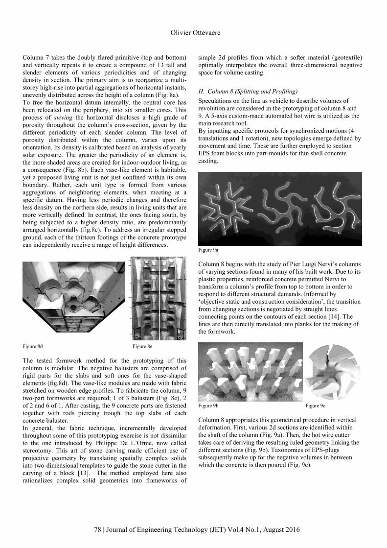
H. Column 8 (Splitting and Profiling)
Speculations on the line as vehicle to describe volumes of
revolution are considered in the prototyping of column 8 and
9. A 5-axis custom-made automated hot wire is utilized as the
main research tool.
By inputting specific protocols for synchronized motions (4
translations and 1 rotation), new topologies emerge defined by
movement and time. These are further employed to section
EPS foam blocks into part-moulds for thin shell concrete
casting.
Figure 9a
Column 8 begins with the study of Pier Luigi Nervi’s columns
of varying sections found in many of his built work. Due to its
plastic properties, reinforced concrete permitted Nervi to
transform a column’s profile from top to bottom in order to
respond to different structural demands. Informed by
‘objective static and construction consideration’, the transition
from changing sections is negotiated by straight lines
connecting points on the contours of each section [14]. The
lines are then directly translated into planks for the making of
the formwork.
Figure 9b Figure 9c
Column 8 appropriates this geometrical procedure in vertical
deformation. First, various 2d sections are identified within
the shaft of the column (Fig. 9a). Then, the hot wire cutter
takes care of deriving the resulting ruled geometry linking the
different sections (Fig. 9b). Taxonomies of EPS-plugs
subsequently make up for the negative volumes in between
which the concrete is then poured (Fig. 9c).
78 | Journal of Engineering Technology (JET) Vol.4 No.1, August 2016
Olivier Ottevaere
I. Column 9 (Entangling and Cracking)
Column 9 expands on the procedure horizontally (Fig. 10a). In
addition to movement, a time factor is introduced. New slab
topologies arise from incremental protocols on a moving line
in space.
Figure 10a
Although the prototype is still in its infancy, early findings
present unique slab topologies, whose forms would be difficult
to preconceive through other means of digital fabrication.
Being de-scribed by successions of straight lines, these
intricate slabs retain an efficient and a direct link to timber
formwork and full scale construction.
Figure 10b
The EPS mould-making method also resonates with the
parallel made earlier on stereotomy, although this time by
operating internally in the carving or slicing of a block (Fig.
10c).
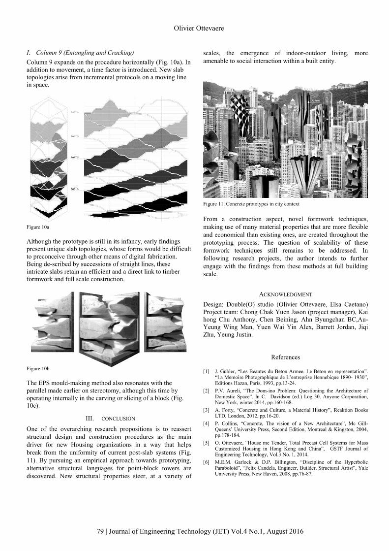
III. CONCLUSION
One of the overarching research propositions is to reassert
structural design and construction procedures as the main
driver for new Housing organizations in a way that helps
break from the uniformity of current post-slab systems (Fig.
11). By pursuing an empirical approach towards prototyping,
alternative structural languages for point-block towers are
discovered. New structural properties steer, at a variety of
scales, the emergence of indoor-outdoor living, more
amenable to social interaction within a built entity.
Figure 11. Concrete prototypes in city context
From a construction aspect, novel formwork techniques,
making use of many material properties that are more flexible
and economical than existing ones, are created throughout the
prototyping process. The question of scalability of these
formwork techniques still remains to be addressed. In
following research projects, the author intends to further
engage with the findings from these methods at full building
scale.
ACKNOWLEDGMENT
Design: Double(O) studio (Olivier Ottevaere, Elsa Caetano)
Project team: Chong Chak Yuen Jason (project manager), Kai
hong Chu Anthony, Chen Beining, Ahn Byungchan BC,Au-
Yeung Wing Man, Yuen Wai Yin Alex, Barrett Jordan, Jiqi
Zhu, Yeung Justin.
References
[1] J. Gubler, “Les Beautes du Beton Armee. Le Beton en representation”. “La Memoire Photographique de L’entreprise Hennebique 1890- 1930”, Editions Hazan, Paris, 1993, pp.13-24.
[2] P.V. Aureli, “The Dom-ino Problem: Questioning the Architecture of Domestic Space”. In C. Davidson (ed.) Log 30. Anyone Corporation, New York, winter 2014, pp.160-168.
[3] A. Forty, “Concrete and Culture, a Material History”, Reaktion Books LTD, London, 2012, pp.16-20.
[4] P. Collins, “Concrete, The vision of a New Architecture”, Mc Gill-Queens’ University Press, Second Edition, Montreal & Kingston, 2004, pp.178-184.
[5] O. Ottevaere, “House me Tender, Total Precast Cell Systems for MassCustomized Housing in Hong Kong and China”, GSTF Journal of Engineering Technology, Vol.3 No. 1, 2014.
[6] M.E.M. Garlock & D.P. Billington, “Discipline of the HyperbolicParaboloid”, “Felix Candela, Engineer, Builder, Structural Artist”, Yale University Press, New Haven, 2008, pp.76-87.
79 | Journal of Engineering Technology (JET) Vol.4 No.1, August 2016
Olivier Ottevaere
[7] J.A. Ochsendorf, “Eladio Dieste as Structural Artist”, “Eladio Dieste, Innovation in Structural Art”, Princeton Architectural Press, New York, 2004, pp.94-96.
[8] D. Wu, “A Towering Achievement”, Arts+Weekend House, The Financial Times, 09/02/2008.
[9] O. Ottevaere, “Quasi-Projection: Aperiodic –concrete formwork forperceived surface complexity”, Acadia, Chicago, 2009.
[10] P. Gros, “Le Dessin de L’Entasis”, In R. Gargiani (ed.) “La Colonne, Nouvelle Histoire de la Construction”, Presses polytechniques and universitaires romandes, Lausanne, 2008, pp.23-31.
[11] L. Glaeser, “The Work of Frei Otto”, The Museum of Modern Art, New York, 1972, pp.105-122.
[12] P. Mivelaz, 2008, “Mushroom Head, Pilzdecke, pilier-champignon: metamorphoses de la dalle sans sommiers”, In R. Gargiani (ed.), ”LaColonne, Nouvelle Histoire de la Construction”, Presses polytechniquesand universitaires romandes, Lausanne, 2008, pp.237-251.
[13] R. Evans, “Drawn Stone”, “The Projective Cast, Architecture and its Three Geometries”, The MIT Press, Cambridge, 1995, pp.179-192.
[14] P.L. Nervi, “The Plasic Richness of Concrete Cast in Place”, “Aesthetics and Technology in Building”, Harvard University Press, Cambridge, 1965, pp. 23-36.
O. Ottevaere (M’75),
80 | Journal of Engineering Technology (JET) Vol.4 No.1, August 2016
Olivier Ottevaere
AUTHOR'S PROFILE
Of Belgian origin, he graduated with a degree in Architecture from the Cooper Union in New York and with an MSc in adaptive architecture and computation from the Bartlett in London. He has practised in New York, Lisbon and London and has taught design studios in Denmark, the UK and from 2005 to 2011 in Switzerland. In 2010, he also was a unit master at the Architectural Association.His interests reside in the conception of space in architecture driven by a hybrid approach between digital and physical design explorations. His current research work seek for structural alternative in reinforced concrete and for new formwork design that are more reusable, adaptive and responsive to concrete as a material.He is currently an Assistant Professor at the University of Hong Kong and continues developing design-research and projects under his initialsdouble(O) studio (www.doubleostudio.com).