new products coolant valve - ckd
TRANSCRIPT

Coolant valveCVE2/CVE3 Series (air operated type)CVSE2/CVSE3 Series (with solenoid valve)
New Product
COOLANT VALVE
New Products
4 CC-769A

55%DOWN
50%DOWN
CVSE2 series 20A.Equivalent to conventional product 25A!
ConventionalCVSE2 Series
Pressure loss at 50 L/min. (0.5MPa)
Pre
ssur
e lo
ss
Port size
[kPa]
Useful to different machines and equipment
Valve side mounted lowwattage actuator
Reliable operationCylinder drive method usingexternal pilot air ensuresreliable operation.
Cutting chip, etc., resistantThis valve has the metal sealstructure to prevent foreignmatters, such as cutting dustand abrasive grains, etc., fromentering into the valve inside.
Low pressure lossIdeal valve flow path shape(patent acquired and patent pending)
Low pressure loss/large flow rate coolant valve, 45 types available.Low pressure (0.5MPa) to high pressure (7.0MPa) is available with port size 10A to 80F.Coolant needs are handled with a wide range of products.
Reducing energy loss!COOLANT VALVE
CVSE Series
CVSE3 Series
CVSE2 Series
An optimum coolant system is realized by reviewing the valves and system.
Proposals for improving coolant devicesProposals for improving coolant devices
CVSE series variations
Flow UPComparison of Cv flow factor (0.5MPa)
CVSE2 Series
Pressure loss50% reduction
Reliable directacting
ModelPort size
CVSE2
CVS3E
Low pressure
Medium pressure
High pressure
Medium pressure
High pressure
Low pressure
10A 15A 20A 25A 32A/F 40A/F 50A/F 65F 80F
0.5MPa
1.0MPa
1.6MPa
3.0MPa
7.0MPa
3.5MPa
7.0MPa
0.3MPa
CVSE3
2 port valve
3 port valve
3 port valve
*2
*1: This model does not incorporate a low-pressure loss shape.*2: Only Rc screw-in type is available.*3: Listed in the General purpose valve (CB-03-1SA).
*2
*3 *3
*2
*1 *1
*1 *1
An ideal flow rate shape has been pursued focusing on zero pressure loss.Pressure loss 50% reduced comparing to conventional. (59% reduced maximum, CKD comparison)
Port size Conventional
6.51118
STEP1
STEP3
The coolant system's optimum
circuit can be found with sizing
software.
STEP2
23
Low pressureloss 2 port valve
CVSE2
3 conventional2 port valvesusedBefore improvement
Afterimprovement
CVSE 23 Series
Coolant valve 2, 3 port valve
Low pressue loss3 port valveCVS3E
20A 25A
25
20
15
10
5
0
15A
20A
25A
5
8
12
New
New
Low pressure loss type 2 port valve
Compatible designs withconventional products
Actuator mounted on the valve side
The product is compatible withconventional products in face-to-facedimensions and specifications,enabling installation in existing facilities.
An accurate direct-acting solenoidvalve is used to open and close thevalve.Power consumption is reduced to2 W from the conventional 4 W.Easy installation
The actuator is generally smaller andeasier to install.
Current consumption isreduced by 50% withaccurate direct-acting type
Adequate reviewing coolantdischargeReviewing pressure loss ofcoolant valve
Downsizing of coolant pumpAchieving energy savingcoolant system
Low pressure loss 3 port valve

Category
Air operated type
With solenoid valve
Air operated type
With solenoid valve
Air operated type
With solenoid valve
Air operated type
With solenoid valve
Air operated type
With solenoid valve
Air operated type
With solenoid valve
Air operated type
With solenoid valve
Workingpressure
rangeMPa
CVE2-***-05
CVSE2-***-05
CVE2-***-10
CVSE2-***-10
CVE2-***-16
CVSE2-***-16
CVE2-***-30
CVSE2-***-30
CVE2-***-70
CVSE2-***-70
CVE3-***-35
CVSE3-***-35
CVE3-***-70
CVSE3-***-70
Model nameNo. of port
Rc3/8 Rc1/2
0 to 0.5
0 to 1
0 to 1.6
0 to 3.0
0 to 7.0
0 to 3.5
0 to 7.0
2 port
3 port
Low
pre
ssur
eM
ediu
m p
ress
ure
Med
ium
pres
sure
Hig
hpr
essu
reH
igh
pres
sure
Intro 1
Air operated 2, 3 port valve (coolant control)(Coolant valve)
Seriesvariation
Intro 2
Port size
Rc3/4 Rc1 Rc1 1/4 32 flange 40 flangeRc1 1/2 Rc2 50 flange
Page
65 flange 80 flange
1
1
1
1
11
11
11
11
19
19
25
25
25
25
CVE/CVSE SeriesSeries variation

Intro 3
Flow characteristics
1. Flow characteristics indicationThe catalog specifications indicate the flow as followings.
UnitindicationComponents Standard
New JIS compliant indication
Pneumaticcomponents
Generalpurpose valves
New JIS compliant indication
Conventional indication
Conventional indication
C and b
S
Cv
Cv
ISO 6358: 1989 Pneumatic fluid power - Components using compressible fluids - Determination of flow-rate characteristicsJIS B8390: 2000 (ISO 6358 translation)
JIS B8373: 1993 " pneumatic 2 port solenoid valve "JIS B8374: 1993 " pneumatic 3 port solenoid valve "JIS B8375: 1993 " pneumatic 4,5 port solenoid valve "JIS B8379: 1995 " pneumatics noise reduction device "ANSI (NFPA) T3.21.3: 1990
IEC 60534-2-3 : 1997 Industrial-process control valves - Part 2-3: Flow capacity - Test proceduresJIS B2005-2-3: 2004 (IEC 60534-2-3 translation)JIS B8471: 2004 " solenoid valve for water "JIS B8472: 1994 " solenoid valve " for steamJIS B8473: 1994 " solenoid valve for fuel "
The general purpose valve flow characters are indicated with capacity coefficient Cv. To comply with old IEC Standards, attempts were made to indicate features with capacity coefficient Av to unify indications with SI units. The Av value was eliminated from the control valve capacity coefficient with JIS B 2005-2-3: 2004 revisions, and only Kv and Cv types are used.The Cv indication is still used to indicate flow features of the general purpose valves. For Av values, conversion values are listed for reference as needed.
Flow formula
is indicated as followings in accordance with practical unit
For steam:
2. Explanation of general purpose valves
Cv : Flow factorW : Flow (kg/h)P1 : Primary absolute pressure (MPa)P2 : Secondary absolute pressure (MPa)K : (1 + 0.0013ts) ts: Degree of superheat
(Saturated vapor K = 1)
Q = 45.16 Cv : (3)
For P2 : (4)
The non-SI adjustment valve capacity coefficient is used commonly worldwide. U.S. gal value indicating the flow of 40 to 100°F city water for one minute through the valve (test part) when the differential pressure is 1 psi.
Cv=Q : (1)
Value indicating city water flow rate passing through valve (test part) as m3/s unit at pressure difference 1 Pa. The value is calculation based on the following formula.
Av = Q : (2)
P1
2W =
97 Cv P1
K
For P2 > : (5)P1
2W =
194 Cv (P1 -P2 ) P2
K
Capacity :coefficient Cv
Capacity :coefficient Av
w
1
P
Cv : Capacity coefficientQ : Flow (U.S. gal/min) (1U.S.gal/min. = 6,309 x 10-5m3/s)
: Fluid density (1b/ft3) (1b/ft3 = 16,018kg/m3) w : 40°F to 100°F (4 to 38 ) water density (1b/ft3) P : Differential pressure (psi) (1psi=6.8948kPa)
P
Av : Capacity coefficient (m2)Q : Flow (m3/s)
: Density of fluid (kg/m3) P : Differential pressure (Pa)
Capacity coefficient Cv
For liquid:
P
G
Cv : Flow factorQ : Flow ( /min.) P : Differential pressure (MPa)G : Specific gravity (water G=1)

Flow formula
is indicated as followings in accordance with practical unit
Capacity coefficient Av
For liquid:
For steam:
Av = 28 x 10-6 Kv = 24 x 10-6 Cv : (8)
Q = 1.9 x 10⁶Av : (6) P
G
Q = 8.1 x 10⁶ Av : (7)
Conversion of capacity coefficient
P (P2 + 0.1)
Kv : Value indicating the flow of 5 to 40 city water as m3/h passing through the valve when the differential pressure is 1 bar.
Cv : Value indicating 60°F city water flow rate passing through valve as US gal/min unit at pressure difference 1lbf/in2 (psi).
Values do not match because test methods for Kv and Cv for pneumatic use differ.
Q : Flow (kg/h)Av : Capacity coefficient (m2) P: Differential pressure (MPa)P1 : Primary side pressure (MPa):
P = P1-P2
P2 : Secondary side pressure (MPa)
Q : Flow ( /min.)Av : Capacity coefficient (m2) P : Differential pressure (MPa)G : Specific gravity (water = 1)
Intro 4

Safety precautionsAlways read this section before starting use.
1
2
3
4
5
123
4
The safety cautions are ranked as "DANGER", "WARNING" and "CAUTION" in this section.
DANGER :
WARNING :
CAUTION:
WARNING
When designing and manufacturing a device using CKD products, the manufacturer is obligated to check that device safety mechanical mechanism, pneumatic control circuit, or water control circuit and the system operated by electrical control that controls the devices is secured.It is important to select, use, handle, and maintain the product appropriately to ensure that the CKD product is used safely.Observe warnings and precautions to ensure device safety.Check that device safety is ensured, and manufacture a safe device.
This product is designed and manufactured as a general industrial machine part.It must be handled by an operator having sufficient knowledge and experience in handling.
Use this product in accordance of specifications.
Observe corporate standards and regulations, etc., related to the safety of device design and control, etc.
Observe warnings and cautions on the pages below to prevent accidents.
Do not handle, pipe, or remove devices before confirming safety.
1
2
This product must be used within its stated specifications.It must not be modified or machined.This product is intended for use as a general-purpose industrial device or part. It is not intended for use outdoors or for use under the following conditions or environment.(Note that this product can be used when CKD is consulted prior to use and the customer consents to CKD product specifications. The customer must provide safety measures to avoid risks in the event of problems.)
Use for special applications requiring safety including nuclear energy, railroad, aviation, ship, vehicle, medical equipment, equipment or applications coming into contact with beverage or food, amusement equipment, emergency shutoff circuits, press machine, brake circuits, or for safeguard.Use for applications where life or assets could be adversely affected, and special safety measures are required.
1. CKD cannot be held liable for any business interruption, loss of profit, personal injury, delay cost, or any other ancillary or indirect loss, cost, or damage resulting from the use of or faults in the use of CKD products.
2. CKD cannot be held responsible for the following damage:(1) Damage resulting from failure of CKD parts due to fire from reasons not attributable to CKD, or by intentional or
negligence of a third party or customer.(2) When a CKD product is assembled into customer equipment, damage that could have been avoided if
customer equipment were provided with functions and structure, etc., generally accepted in the industry.(3) Damage resulting from use exceeding the scope of specifications provided in CKD catalogs or instruction
manuals, etc., or from actions not following precautions for installation, adjustment, or maintenance, etc.,(4) Damage resulting from product modifications not approved by CKD, or from faults due to combination with other software or other connected devices.
Inspect and service the machine and devices after confirming safety of the entire system related to this product.Note that there may be hot or charged sections even after operation is stopped.When inspecting or servicing the device, turn off the energy source (air supply or water supply), and turn off power to the facility. Discharge any compressed air from the system, and pay enough attention to possible water leakage and leakage of electricity.When starting or restarting a machine or device that incorporates pneumatic components, make sure that the system safety, such as pop-out prevention measures, is secured.
ISO4414, JIS B8370 (pneumatic system rules)JFPS2008 (principles for pneumatic cylinder selection and use)Including High Pressure Gas Maintenance Law, Occupational Safety and Sanitation Laws, other safety rules, body standards and regulations, etc.
When a dangerous situation may occur if handling is mistaken leading to fatal or serious injuries, or when there is a high degree of emergency to a warning.
When a dangerous situation may occur if handling is mistaken leading to fatal or serious injuries.
When a dangerous situation may occur if handling is mistaken leading to minor injuries or physical damage.
Note that some items described as "CAUTION" may lead to serious results depending on the situation. In any case, important information that must be observed is explained.
Disclaimer
Intro 5

Intro 6
Design & Selection
This product can not be used as an emergency shut off valve.Valves in this catalog are not designed to ensure safety suchas emergency shutoff. When using in this system, take sepa-rate measures that will ensure safety.
Take measures to prevent harm to operators or ob-jects if this product fails
WARNING
CAUTION Leakage current from other fluid control componentsWhen operating the solenoid valve with a programmable con-troller, etc., check that leakage current from the program-mable controller's output is within the specifications below.Failure to observe this could lead to malfunctions.
Liquid ringIn fluid flow, if a liquid ring circuit is created, pressure couldrise when temperature fluctuates and prevent operation. Pro-vide a relief valve so that a liquid ring circuit is not created.
VibrationMount and use in a place with no vibration.
Of to secure safety.
Fluid control components warning and cautionsAlways read this section before starting use.
1. Safety designing
Working fluid(1) The adequacy of coolants has not been evaluated. If cool-
ant contains high levels of chlorine or sulfur, materials usedat wetted sections could be adversely affected. Confirmthe adequacy when making a selection. Non-corrosive flu-ids refers to fluids that do not affect or are not affectedwhen they contact the valve's wetted section materials.Wetted section materials: Cast steel (nickel plating), stain-
less steel, copper, nitrile rubberor fluoro rubber, epoxy resin ad-hesive
(2) Wear powder could be generated when internal parts areworn through valve operation. This could flow to the sec-ondary side of the valve.
Quality of fluidRust and dirt in fluid could cause operation faults or leaksand obstruct product performance.
Fluid temperatureUse within the fluid temperature range.
WARNING
2. Working fluid
100 VAC: 3mA or less200 VAC: 1.5mA or less24 VDC: 1mA or lessmust be maintained.
CR circuit
Triode ACSwitch
LeakageCurrent
C
R
Solenoid valve body side
Programmablecontroller side
External pilot air(1) Drainage measures: Compressed air contains high lev-
els of drainage (water, oxidized oil, tar, foreign matter)that may reduce pneumatic component reliability. Improveair quality by dehumidifying with an after cooler or dryer,removing foreign matter with a filter, and removing tarwith a tar removal filter, etc.
(2) Pre-lubrication: This series is used with pre-lubricationspecifications, so a lubricator is not required. When lubri-cating, continuously lubricate so that the component doesnot run out of lubrication. Use the turbine oil Class 1/ISOVG32 (#90) or equivalent.
(3) Filter: Install a filter with a 5 m or less filter element.
CVSE Series can not be used in the flammable en-vironment. When using in a flammable environment,change the model to the CVE Series and provide aseparate explosion-proof solenoid valve in the pilotair circuit.
Do not use this product in an environment in which cor-rosive gases could impregnate configuration materials.
Do not use this product near heat-generating ele-ments or where it may be subject to radiated heat.
Use the product within the ambient temperaturerange.
Take the appropriate freezing prevention such as thecountermeasures for cold district use.
When insulating the solenoid valve, etc., do not treatthe coil.
Take appropriate safeguards for protective structureslisted in catalog specifications. Consult with CKDwhen using outdoors.
Take appropriate safeguards when using this prod-uct in places where oil or spatter from welding, etc.,contact could occur.
If levels of dust are high in the area, provide a si-lencer on the exhaust port or face the elbow jointdownward so that dust does not get inside.
Take appropriate safeguards when using this prod-uct in places where water contact could occur.
3. Working environment
WARNING

When using the product with continuous energizingand low frequency, consult with CKD.
If the product has not been used for more than amonth, carry out trial operation.
If suspending use for more than a month after a fluidis used, completely remove fluid remaining inside.Rust could form if fluids are left inside, and couldresult in operation faults or leaks.If residual water cannot be removed, operate thevalve several times a days to ensure correct use.
4. How to use
WARNING
Do not touch coils or actuators with hands or otherwisewhile power is on or immediately after turning power on.The solenoid valve's coil and actuator will heat up when elec-tricity is passed through them. Depending on the product,directly touching these sections could cause burns.
Do not touch electric wiring connections with hands or otherwise (barecharged sections) while power is on. An electric shock could occur.Touching electric wire connections while power is on couldlead to electrical shock.
Use the product within the working pressure range.
Installation & Adjustment
CAUTION
Always thoroughly read the Instruction Manual be-fore installing this product.
Do not apply external force on the coil section ofsolenoid valve at installation.
After installing, check for leaks from pipes and for wire con-nections, and check that the product is correctly installed.
1. Installation
CAUTION
Observe the valid thread length for piping. Chamferthe end of the screw a half-pitch.
Before piping, flush the inside of the pipe with 0.3MPa of air, and remove foreign matter such as dirt,metal chips, rust, and sealing tape.
If excessive sealant (tape, gel) is applied when pip-ing, it could enter the product and cause operationfaults.
When applying or wrapping sealant on piping mate-rial, apply it or wind it from the pipe end along thescrew and leave 1.5 to 2 threads uncovered.
2. Piping
Pilot air pressureUse the pilot air in accordance with specifications.
Do not step the valve, nor put the heavy things on it.
CAUTION Secure sufficient space for maintenance and inspec-tion.
CAUTION
5. Securing of space
Dirt or foreign matter in fluid may prevent the productfrom functioning correctly. Install an 80 mesh or higherfilter for water flow, and a 5 m or less filter for air flow.
Do not pipe with using the solenoid valve section.Failure to observe this the product could be dam-aged. (For solenoid valve)
Install the by-pass circuit, and use the elbow unionwhen piping to simplify the maintenance or repairwork.
When controlling fluid in a tank, pipe at a level slightlyabove the bottom of the tank.
When piping the CVE or CVSE Series, note the sup-ply port on the unit and pilot operation side.
Intro 7
X
Y
P
Y
P
IN
Model no.
CVE2
CVE22
CVSE2/CVSE22
CVE3
CVSE3
Supply port pilotoperation side
Supply port pilotoperation side
Note) Pipe the unit supply port so that the arrow on the body matches the fluid flow direction. If supplied in reverse, internal components could be damaged when the valve operates.
CVE/CVSE Series

During Use & Maintenance
To ensure that the product is used optimally, regu-larly inspect the product every six months. This fre-quency varies with the frequency of use.
WARNING
CAUTION
Read the instruction manual thoroughly before start-ing maintenance to ensure correct operation.
Turn power off and release fluids or pressure beforestarting maintenance.
Care must be taken not to clog the strainer-filter.
1. Maintenance & Inspection 2. Assembling & Disassembling
If the electrical circuit is susceptible to solenoid surge,use a solenoid with a surge suppressor (option), orinsert a surge absorber, etc., parallel to the solenoid.
Use a wire more than 0.5mm2 of nominal sectionarea as the reference. Check that no excessive forceis applied to leads.
Use of a switching circuit that does not cause con-tact chatter will lengthen the life of the solenoid valveand motorized valve.
Wiring when a solenoid valve is installed(1) Refer to connections on page 10 in the introduction when
wiring to a DIN terminal box or T-type terminal box.(2) The size of the screw for the DIN terminal box's junction
box outlets can be changed from Pg9 to G1/2 using theoptional connector below.
(3) Coil orientation is changed by 180°. Turn the coil onlywhen reversing the electric wire connection method. Donot lose internal parts when removing the coil.
Use the product within the allowable voltage range.Use outside of the allowable voltage range may leadto operation faults or coil damage.
Use a breaker such as the fuse, etc., on the controlcircuit for maintenance of electric equipment.
CAUTION
3. Wiring
23 to 25
31 to 33
41 to 43
62 to 65
83 to 86
97 to 100
104 to 108
132 to 136
<<Products/body section piping>>
Nominal piping diameterRc1/4
Rc3/8
Rc1/2
Rc3/4
Rc1
Rc1 1/4
Rc1 1/2
Rc2
Recommended piping tightening torque (N m)
7 to 9
Nominal piping diameterRc1/8
Recommended piping tightening torque (N m)
Refer to the table below for tightening torque when pilot air piping.
Refer to the table below for tightening torque when piping.
* Order model No. CVS2-CONNECTOR-F4-202936
Hexagon head 2425
16
Pg9 G /12
A spring is used in the cylinder cover. When disas-sembling this type, the spring could pop out andcause injuries, so take care.
The 2-port NC (normally closed) has a snap ring to preventthe spring from popping out. Do not remove the snapring.
WARNING
CAUTION
When cleaning the product, use a low-polluting clean-ing agent such as a neutral detergent. (Note that rub-ber parts must be replaced if they expand.)
Consult with CKD on questions about consumables,etc.
Intro 8
CVE/CVSE Series

Assembling pilot solenoid valve (for solenoid valve)If the pilot solenoid valve has been disassembled, assemble it as follows.
Gasket direction (for solenoid valve)Check the gasket installation direction. Check the installation direction before reassembling.
CVSE2-ACTUATOR-0 - Rated voltage*1
(1) Coil sideDisassemblingLoosen the cross headed pan head machine screw, and lift up the coilassembly. The outer spring, plunger assembly, and O ring are removed.ReassemblingSet parts in the sequence of the O ring, plunger assembly, outer spring,and coil assembly. Tighten cross headed pan head machine screwwith 0.7 to 1.1N m.
(2) Guard sideDisassemblingLoosen the cross headed pan head machine screw, and remove thecover. The valve element spring, valve element guide assembly, andO ring are removed.ReassemblingSet parts in the sequence of the O ring, valve element guide assembly,valve element spring, and cover. Tighten cross headed pan headmachine screw with 0.7 to 1.1 N m.
Note 1: Do not lose the components such as springs during disassembly.
Note 2: The coil assembly direction is changed 180°. Loosen and change the cross-headed pan head machine screw.
Note 3: Turbine oil is applied to the plunger as a lubricant.
Pilot solenoid valve (actuator assembly kit) model no. for CVSE
Note 1: Indicate the coil option symbol in field *1.
Cross headed pan headmachine screw
Body assembly
Cross headed flathead screw
Valving elementguide assembly
Valving elementspring
Guard
O ring
O ring
Plunger assembly
Coil assembly
Outer spring
Note 2
CVSE22,CVSE3CVSE2
NO (normally open) type, 3 port valveNC (normally closed) type
Port R Port R
Gasket
Intro 9
CVE/CVSE Series

DIN terminal box (Pg9), DIN terminal box with indi-cator light DIN terminal box (Pg9)(1) Use the following cabtire cable.
Cable outer diameter: 4.5 to 7, Nominal sectionalarea: 0.75 mm2
(2) Insert the crimp terminal for copper wires into thecabtire cable's lead wire, and crimp the terminal with thedesignated tool. M3 terminal screws are used with theterminal box.
(3) Tighten screws with the following tightening torque.• Set screw tightening torque: 0.5 N•m• Terminal screw tightening torque: 0.5 N•m
* The orientation of the cable lead out port is changed by re-moving the terminal box from the case, rotating it by 180°,then replacing the terminal box into the case.
How to wire terminal box T type terminal box (G1/2), T type terminal box withindicator light(1) Use the following cabtire cable.
• Nominal section area: 0.75mm2
(2) Insert the crimp terminal for copper wires into the cabtirecable's lead wire, and crimp the terminal with the desig-nated tool. M3 terminal screws are used with the termi-nal box.
(3) Tighten screws with the following tightening torque.• Set screw tightening torque: 0.5 N•m• Terminal screw tightening torque: 0.5 N•m
*Changing direction of T type terminal boxChange the orientation of the T-type terminal block from thedefault state as follows.(1) Hold the width across flats (25 width) of the T-type termi-
nal box with a tool (monkey wrench, spanner, etc.), andloosen it by turning counterclockwise.
(2) Loosen the lock nut.(3) Rotate the T-type terminal box clockwise to 15° before
the required position.(4) Tighten the lock nut to the coil by hand until it is moder-
ately tight.(5) Hold the width across flats of the T-type terminal box with
a tool, and rotate it (approx. 15°) to tighten it to the re-quired position.
Note: When further tightening the terminal box to change theorientation from the default, rotate it within 1/2-turn.
Put the case on thebody, then thetightensetscrews.
Setscrew Gasket
Washer
CapPut the cap, the washer,the gasket, then the case on in order.Fix the cable with the cap.
CaseNote: 180° rotation permissible
Voltage terminalGland
Gasket
Ground terminal
Coil assembly
Bare crimp terminalfor copper wire
Ground cable
Cabtire cable
Insert the gasket and gland into the coil terminal.
Terminal caulking
Lead wire sheath pealing
2
6
7
3
4 GlandFix the crimp terminal.
5
1
Wire as to steps.1 7
JIS C3306 VCTF 0.75mm2
Outer diameter 4.5 to 7
Note: distinction not required
* marked parts are not included.
Cap assembly
Gasket
Free terminal setscrew
* Bared crimp terminal for copper wire
Fixing bracket
Coil lead wire
Set screwLock nut
Terminal box
* Cable connector
* 600V insulated vinyl Cabtire cableJIS C 3312 VCT 0.75mm2
JIS C2805 R1.25-3
Intro 10
CVE/CVSE Series

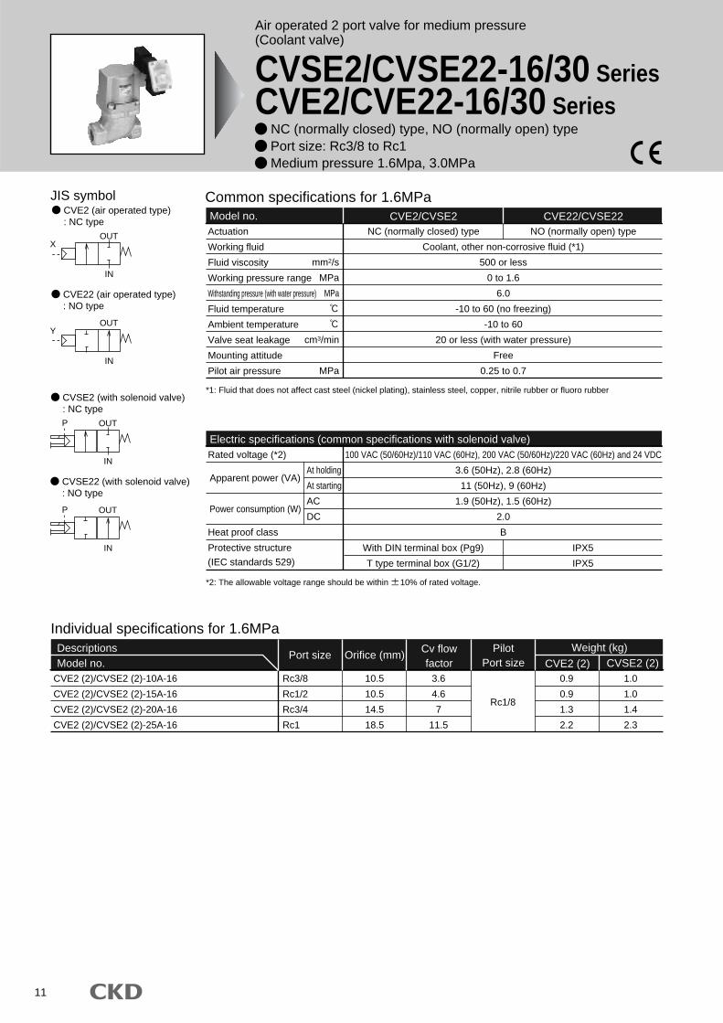
JIS symbol
IN
XOUT
IN
YOUT
IN
P OUT
IN
P OUT
CVSE2 (with solenoid valve): NC type
CVSE22 (with solenoid valve): NO type
CVE2 (air operated type): NC type
CVE22 (air operated type): NO type
Common specifications for 0.5MPaModel no. CVE2/CVSE2 CVE22/CVSE22Actuation
Working fluid
Fluid viscosity
Working pressure range
Withstanding pressure (with water pressure)
Fluid temperature
Ambient temperature
Valve seat leakage
Mounting attitude
Pilot air pressure
Water-hammer (references)
Coolant, other non-corrosive fluid
500 or less
0 to 0.5
2.0
-10 to 60 (no freezing)
-10 to 60
20 or less (with water pressure)(*2)
Free
0.25 to 0.7
1 or less (with steel pipe 10m, full pressure 0.5MPa and velocity of moving fluid 5m/sec.)
NC (normally closed) type NO (normally open) type
Electric specifications (common specifications with solenoid valve)Rated voltage
Heat proof class
Protective structure
At holding
At starting
AC
DC
100 VAC (50/60Hz)/110 VAC (60Hz), 200 VAC (50/60Hz)/220 VAC (60Hz) and 24 VACDC
3.6 (50Hz), 2.8 (60Hz)
11 (50Hz), 9 (60Hz)
1.9 (50Hz), 1.5 (60Hz)
2.0
B
Grommet lead wire
With DIN terminal box (Pg9)
T type terminal box (G1/2)
IPX2
IPX5
IPX5
*1: Fluid that does not affect cast steel (nickel plating), stainless steel, nitrile rubber, fluoro rubber, or epoxy resin adhesive*2: 1cm3/min. or less for port size 10A (Rc3/8)
Individual specifications for 0.5MPaDescriptionsModel no.
Port sizeWeight (kg)Pilot
Port size CVE2 (2) CVSE2 (2)CVE2 (2)/CVSE2 (2)-10A-05
CVE2 (2)/CVSE2 (2)-15A-05
CVE2 (2)/CVSE2 (2)-20A-05
CVE2 (2)/CVSE2 (2)-25A-05
CVE2 (2)/CVSE2 (2)-32A-05
CVE2 (2)/CVSE2 (2)-32F-05
CVE2 (2)/CVSE2 (2)-40A-05
CVE2 (2)/CVSE2 (2)-40F-05
CVE2 (2)/CVSE2 (2)-50A-05
CVE2 (2)/CVSE2 (2)-50F-05
CVE2 (2)/CVSE2 (2)-65F-05
CVE2 (2)/CVSE2 (2)-80F-05
Rc3/8
Rc1/2
Rc3/4
Rc1
Rc1 1/4
32 flange
Rc1 1/2
40 flange
Rc2
50 flange
65 flange
80 flange
10
14
19
24
31
31
40
40
50
50
65
79
2.8
6.5
11
18
28
28
43
43
70
70
70
100
Rc1/8
0.35
0.6
1.2
1.8
2.7
5.3
4.4
7.0
6.5
9.6
19.5
24.0
0.45
0.7
1.3
1.9
2.8
5.4
4.5
7.1
6.6
9.7
19.5
24.0
Orifice (mm)Cv flowfactor
(*1)
Apparent power (VA)
Power consumption (W)
(IEC standards 529)
mm2/s
MPa
MPa
cm3/min
MPa
MPa
*3: The allowable voltage range should be within 10% of rated voltage.
Air operated 2 port valve for low pressure(Coolant valve)
CVSE2/CVSE22-05/10 SeriesCVE2/CVE22-05/10 Series
NC (normally closed) type, NO (normally open) type Port size: Rc3/8 to Rc2, 32 to 80 flunge Low pressure 0.5Mpa, 1.0MPa
1
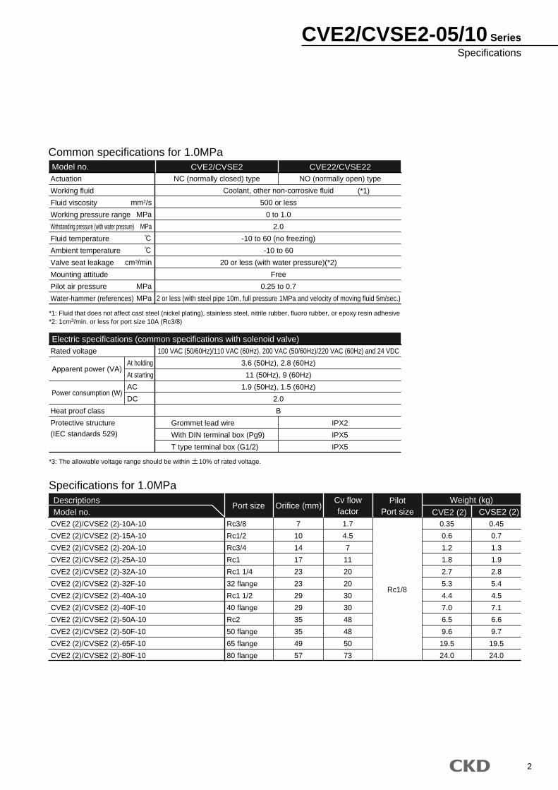
CVE2/CVSE2-05/10 SeriesSpecifications
2
Common specifications for 1.0MPaModel no. CVE2/CVSE2 CVE22/CVSE22Actuation
Working fluid
Fluid viscosity
Working pressure range
Withstanding pressure (with water pressure)
Fluid temperature
Ambient temperature
Valve seat leakage
Mounting attitude
Pilot air pressure
Water-hammer (references)
Coolant, other non-corrosive fluid
500 or less
0 to 1.0
2.0
-10 to 60 (no freezing)
-10 to 60
20 or less (with water pressure)(*2)
Free
0.25 to 0.7
2 or less (with steel pipe 10m, full pressure 1MPa and velocity of moving fluid 5m/sec.)
NC (normally closed) type NO (normally open) type
Electric specifications (common specifications with solenoid valve)Rated voltage
Heat proof class
Protective structure
At holding
At starting
AC
DC
100 VAC (50/60Hz)/110 VAC (60Hz), 200 VAC (50/60Hz)/220 VAC (60Hz) and 24 VDC
3.6 (50Hz), 2.8 (60Hz)
11 (50Hz), 9 (60Hz)
1.9 (50Hz), 1.5 (60Hz)
2.0
B
IPX2
IPX5
IPX5
*1: Fluid that does not affect cast steel (nickel plating), stainless steel, nitrile rubber, fluoro rubber, or epoxy resin adhesive*2: 1cm3/min. or less for port size 10A (Rc3/8)
Specifications for 1.0MPaDescriptionsModel no.
Port sizeWeight (kg)Pilot
Port size CVE2 (2) CVSE2 (2)CVE2 (2)/CVSE2 (2)-10A-10
CVE2 (2)/CVSE2 (2)-15A-10
CVE2 (2)/CVSE2 (2)-20A-10
CVE2 (2)/CVSE2 (2)-25A-10
CVE2 (2)/CVSE2 (2)-32A-10
CVE2 (2)/CVSE2 (2)-32F-10
CVE2 (2)/CVSE2 (2)-40A-10
CVE2 (2)/CVSE2 (2)-40F-10
CVE2 (2)/CVSE2 (2)-50A-10
CVE2 (2)/CVSE2 (2)-50F-10
CVE2 (2)/CVSE2 (2)-65F-10
CVE2 (2)/CVSE2 (2)-80F-10
Rc3/8
Rc1/2
Rc3/4
Rc1
Rc1 1/4
32 flange
Rc1 1/2
40 flange
Rc2
50 flange
65 flange
80 flange
7
10
14
17
23
23
29
29
35
35
49
57
Rc1/8
0.35
0.6
1.2
1.8
2.7
5.3
4.4
7.0
6.5
9.6
19.5
24.0
0.45
0.7
1.3
1.9
2.8
5.4
4.5
7.1
6.6
9.7
19.5
24.0
Orifice (mm)
1.7
4.5
7
11
20
20
30
30
48
48
50
73
Cv flowfactor
(*1)
Apparent power (VA)
Power consumption (W)
(IEC standards 529)
Grommet lead wire
With DIN terminal box (Pg9)
T type terminal box (G1/2)
mm2/s
MPa
MPa
cm3/min
MPa
MPa
*3: The allowable voltage range should be within 10% of rated voltage.

CVE2/CVSE2-05/10 Series
3
A
CVE2 20A
CVSE2
2
2
0
0
B
S
10
10515A 2G
Actuation
G Assemblydirection
B Port size
C Working pressure range
E Coil
F Otheroptions
H Voltage
D Body/sealant combination
Air operated type
With solenoid valve
How to order
*1:*2:*3:
*4:
Model: CVSE2 : With solenoid valve (2 port)G Actuation : NO (normally open) typePort size : Rc1/2Working pressure range : 0 to 0.5MPaBody/sealant combination
: Body-cast iron (plating) and sealant-nitrile rubberCoil : With DIN terminal box (Pg9)Other options : With surge suppressorG Assembly direction : No optionG Voltage : 100 VAC (50/60Hz) and 110 VAC (60Hz)
<Example of model number>
CVSE22-15A-05-02GS-1
A
B
C
D
E
F
G
F
F
H
Mounting plate (B in ) can be installed for port size 10A, 15A, 20A or 25A.Indicate SB in if both surge suppressor and mounting plate are selected.A surge suppressor is attached for the lead wire coil, while assembled in the terminal box for the coil with terminal box.Manual override (non-locking) specifications are standard for solenoid valve.
Blank
2
NC (normally closed) type
NO (normally open) type
CVE2 CVSE2
Model no.
ActuationA
Port sizeB
1
2
3
100 VAC (50/60Hz)
110 VAC (60Hz)
200 VAC (50/60Hz)
220 VAC (60Hz)
24 VDC
VoltageH
2C
2G
2H
3T
3R
Standard Grommet lead wire
With DIN terminal box (Pg9)
With DIN terminal box with indicator light (Pg9)
T type terminal box (G1/2)
With T type terminal box with indicator light (G1/2)
CoilE
Blank
S
B
No option
With surge suppressor
Mounting plate
Other optionsF
05
10
0 to 0.5MPa
0 to 1.0MPa
Working pressure rangeC
0
B
Standard
Option
Body
Cast iron (plating)
Cast iron (plating)
Sealant
Nitrile rubber
Fluoro rubber
Body/sealant combinationD
Symbol Descriptions
Option
10A
15A
20A
25A
32A
32F
40A
40F
50A
50F
65F
80F
Rc3/8
Rc1/2
Rc3/4
Rc1
Rc1 1/4
32 flange
Rc1 1/2
40 flange
Rc2
50 flange
65 flange
80 flange
Assembly directionG
Blank
X
Y
Z
R
No option
Cylinder guard 90° rotation
Cylinder guard 180° rotation
Cylinder guard 270° rotation
Mounting plate 180° reverse rotation <air operated type>
Coil 180° reverse rotation <with solenoid valve>
Mounting plate and coil 180° reverse rotation <with solenoid valve>
CVE2
CVSE2
Model no.
Air operated type(2 port)
With solenoid valve(2 port)
Refer to the following page for the layout drawing.
*1*2*3*4

4
CVE2/CVSE2-05/10 Series
Assembly directionG
CVSE2 (with solenoid valve) *5Symbol
Direction
Arrangement
Blank (standard)
Without rotation
X *6
Cylinder guard 90° rotation
Y *6
Cylinder guard 180° rotation
Z *6
Cylinder guard 270° rotation
R *6
Coil reverse rotation
Symbol
Direction
Arrangement
B (mounting plate)
Without rotation
B-X
Cylinder guard 90° rotation
B-Y *7
Cylinder guard 180° rotation
Mounting plate reverse rotation
B-Z *7
Cylinder guard 270° rotation
Mounting plate reverse rotation
B-R *8
Coil reverse rotation
Mounting plate reverse rotation
Symbol
Direction
Arrangement
B (mounting plate)
Without rotation
B-R *9
Mounting plate reverse rotation
CVSE2 (with solenoid valve) *1,5
CVE2 (air operated type) *1,5
*5: Facing IN port right and viewed from top, turning angle to clockwise is indicated.*6: Not available for port size 65F/80F.*7: Mounting plate is assembled in the 180° opposite side.*8: Mounting plate of port size 10A is installed from bottom, so only coil is reversely rotated.*9: Not available for port size 10A.
indicates flow path direction, while indicates pilot ports IN.

5
*1: The value in ( ) indicates an option.*2: This internal structure drawing is for 15A to 50A. For 10A, 65F or 80F, consult with CKD.
*Drawing indicates no optional assembly direction.
Internal structure and parts list
Dimensions
CVSE*-10A-05/10-*2C
CVSE*-15A-05/10-*2C
CVSE*-20A-05/10-*2C
CVSE*-25A-05/10-*2C
CVSE*-32A-05/10-*2C
CVSE*-40A-05/10-*2C
CVSE*-50A-05/10-*2C
A
50
71
80
90
125
140
160
B
24
29
35
43
55
61
76
C
12
14.5
17.5
21.5
27.5
30.5
38
D
47.5
71.5
83.5
102
130.5
156.5
178
E
104.5
131
146
168.5
203
232
261
F
32
43
53
63
77
95
113
Rc3/8
Rc1/2
Rc3/4
Rc1
Rc1 1/4
Rc1 1/2
Rc2
N
48.5
49.5
53
57.5
64.5
72.5
82.5
Model no.
No.
1
2
3
4
5
6
7
8
9
10
Parts name
Pilot solenoid valve
Cylinder guard
Spring
Piston
Adaptor
Piston rod
Main valving element
Body
Valve seat
O ring
Rod packing seal
Material
-
ADC12
SWP
A2017
SUS303
SUS304
SUS420J2
FCD450
SUS420J2
NBR (FKM)
NBR (FKM)
Aluminum alloy die-casting
Piano wire
Aluminum
Stainless steel
Stainless steel
Stainless steel
Cast iron (plating)
Stainless steel
G
Nitrile rubber(Fluoro rubber)Nitrile rubber(Fluoro rubber)
CVSE2
CVSE2/CVSE22-10A to 50A-05/10-*2C (Rc screw-in type)
R
N
R
P
B
C
F
D
E
15.5
Rc1/8
19.5(300)22
A
M5Exhaust port
Non-lockingmanual
OUT IN
2-G
4
5
6
7
8
9
3
2
1
10
CVSE2-05/10 Series

6
*Drawing indicates no optional assembly direction.
CVSE*-32F-05/10-*2C
CVSE*-40F-05/10-*2C
CVSE*-50F-05/10-*2C
CVSE*-65F-05/10-*2C
CVSE*-80F-05/10-*2C
A
170
180
180
210
240
D
130.5
156.5
178
199
214
E
243
271.5
300.5
347.5
367.5
H
135
140
155
175
185
K
35
41
53
68
82
L
100
105
120
140
150
M
12
12
14
16
16
N
64.5
72.5
82.5
101
111
Model no.
Dimensions
80F
Refer to pages 9 and 10 for details on the coil options and mounting plates.
Optional dimensions
CVSE2/CVSE22-32F to 80F-05/10-*2C (flange type)
22
M
A
15.519.5 (300)
D
E
NRc1/8
M5Exhaust port
Non-locking manual
H
4- 19
L
K
8- 19
L
K
CVSE2-05/10 SeriesDimensions

7
Internal structure and parts list
Dimensions
No.
1
2
3
4
5
6
7
8
9
Parts name
Cylinder guard
Piston
Adaptor
Piston rod
Main valving element
Body
Valve seat
Spring
O ring
Rod packing seal
Material
ADC12
A2017
SUS303
SUS304
SUS420J2
FCD450
SUS420J2
SWP
NBR (FKM)
NBR (FKM)
Aluminum alloy die-casting
Aluminum
Stainless steel
Stainless steel
Stainless steel
Cast iron (plating)
Stainless steel
Piano wireNitrile rubber(Fluoro rubber)Nitrile rubber(Fluoro rubber)
*1: The value in ( ) indicates an option.*2: This internal structure drawing is for 15A to 50A. For 10A, 65F or 80F, consult with CKD.
CVE*-10A-05/10-*
CVE*-15A-05/10-*
CVE*-20A-05/10-*
CVE*-25A-05/10-*
CVE*-32A-05/10-*
CVE*-40A-05/10-*
CVE*-50A-05/10-*
A
50
71
80
90
125
140
160
B
24
29
35
43
55
61
76
C
12
14.5
17.5
21.5
27.5
30.5
38
D
43.5
67.5
79.5
98
126.5
152.5
174
E
73.5
100
115
137.5
172
201
230
F
32
43
53
63
77
95
113
G
Rc3/8
Rc1/2
Rc3/4
Rc1
Rc1 1/4
Rc1 1/2
Rc2
N
37
38
41.5
46
53
61
71
Model no.
CVE2
CVE2/CVE22-10A to 50A-05/10-** (Rc screw-in type)
Y
X
OUT IN
A
N
B
C
14.6
F
10D E
2-Rc1/8
2-G
2
1
3
4
5
6
7
8
9
CVE2-05/10 Series

8
CVE2/CVE22-32F to 80F-05/10-** (flange type)
Dimensions
80F
CVE*-32F-05/10-*
CVE*-40F-05/10-*
CVE*-50F-05/10-*
CVE*-65F-05/10-*
CVE*-80F-05/10-*
A
170
180
180
210
240
D
126.5
152.5
174
199
214
E
212
240.5
269.5
347.5
367.5
H
135
140
155
175
185
K
35
41
53
68
82
L
100
105
120
140
150
M
12
12
14
16
16
N
53
61
71
101
111
Model no.
Refer to page 9 for the mounting plate.
Optional dimensions
D
E
N
A
M
14.6
10
2-Rc1/8
H
K
L
4- 19
8- 19
L
K
CVE2-05/10 SeriesDimensions

9
CVE2/CVSE2-05/10 Series
Optional dimensions
CV*E2*-15A-05/10-**B
CV*E2*-20A-05/10-**B
CV*E2*-25A-05/10-**B
P
90
95
105
Q
70
75
85
R
45
50
55
S
2.3
3.2
3.2
T
30
40
45
Model no.
*Use the body setscrews if fixed without mounting plate. (Thread size: M4 depth 7)
-10A-05/10-** B
-15A/20A/25A-05/10-** B / B-R / B-Y -15A/20A/25A-05/10-** B-X / B-Z
*Drawing indicates B . *Drawing indicates B-X .
Mounting plate
CVE2/CVE22
CVSE2/CVSE22
Mounting plate
CVE2/CVE22
CVSE2/CVSE22
Mounting plate
CVE2/CVE22
CVSE2/CVSE22
50
62
23IN port
2 8
20
T
S
Q
R
9
12
T
S
P
Q
12
R
9
P
2- 6

10
Optional dimensions
2G2H
3T3R
With DIN terminal box (Pg9)
DIN terminal box with indicator light (Pg9)
CVSE2/CVSE22-*-05/10-*
T type terminal box (G1/2)
T type terminal box with indicator light (G1/2)
CVSE2/CVSE22-*-05/10-*
P P
22
24
15.5
18
4453
(38)
44.5
Applicable cable
Pg9
15.5
3625
.5
4616
G1/2
(54.5)
(85.5)
35
(O.D. 4.5 to 7)
CVE2/CVSE2-05/10 SeriesOptional dimensions
11
Air operated 2 port valve for medium pressure(Coolant valve)
CVSE2/CVSE22-16/30 SeriesCVE2/CVE22-16/30 Series
NC (normally closed) type, NO (normally open) type Port size: Rc3/8 to Rc1 Medium pressure 1.6Mpa, 3.0MPa
JIS symbol
IN
XOUT
IN
YOUT
IN
P OUT
IN
P OUT
CVSE2 (with solenoid valve): NC type
CVSE22 (with solenoid valve): NO type
CVE2 (air operated type): NC type
CVE22 (air operated type): NO type
Common specifications for 1.6MPaModel no. CVE2/CVSE2 CVE22/CVSE22Actuation
Working fluid
Fluid viscosity
Working pressure range
Withstanding pressure (with water pressure)
Fluid temperature
Ambient temperature
Valve seat leakage
Mounting attitude
Pilot air pressure
Coolant, other non-corrosive fluid (*1)
500 or less
0 to 1.6
6.0
-10 to 60 (no freezing)
-10 to 60
20 or less (with water pressure)
Free
0.25 to 0.7
NC (normally closed) type NO (normally open) type
Electric specifications (common specifications with solenoid valve)Rated voltage (*2)
Heat proof class
Protective structure
At holding
At starting
AC
DC
100 VAC (50/60Hz)/110 VAC (60Hz), 200 VAC (50/60Hz)/220 VAC (60Hz) and 24 VDC
3.6 (50Hz), 2.8 (60Hz)
11 (50Hz), 9 (60Hz)
1.9 (50Hz), 1.5 (60Hz)
2.0
B
With DIN terminal box (Pg9)
T type terminal box (G1/2)
IPX5
IPX5
*1: Fluid that does not affect cast steel (nickel plating), stainless steel, copper, nitrile rubber or fluoro rubber
Individual specifications for 1.6MPaDescriptionsModel no.
Port sizeWeight (kg)Pilot
Port size CVE2 (2) CVSE2 (2)CVE2 (2)/CVSE2 (2)-10A-16
CVE2 (2)/CVSE2 (2)-15A-16
CVE2 (2)/CVSE2 (2)-20A-16
CVE2 (2)/CVSE2 (2)-25A-16
Rc3/8
Rc1/2
Rc3/4
Rc1
10.5
10.5
14.5
18.5
3.6
4.6
7
11.5
0.9
0.9
1.3
2.2
1.0
1.0
1.4
2.3
Rc1/8
Orifice (mm)Cv flowfactor
Apparent power (VA)
Power consumption (W)
(IEC standards 529)
mm2/s
MPa
MPa
cm3/min
MPa
*2: The allowable voltage range should be within 10% of rated voltage.

Common specifications for 3.0MPaModel no. CVE2/CVSE2 CVE22/CVSE22Actuation
Working fluid
Fluid viscosity
Working pressure range
Withstanding pressure (with water pressure)
Fluid temperature
Ambient temperature
Valve seat leakage
Mounting attitude
Pilot air pressure
Coolant, other non-corrosive fluid (*1)
500 or less
0 to 3.0
6.0
-10 to 60 (no freezing)
-10 to 60
20 or less (with water pressure)
Free
0.25 to 0.7
NC (normally closed) type NO (normally open) type
Electric specifications (common specifications with solenoid valve)Rated voltage (*2)
Heat proof class
Protective structure
At holding
At starting
AC
DC
100 VAC (50/60Hz)/110 VAC (60Hz), 200 VAC (50/60Hz)/220 VAC (60Hz) and 24 VDC
3.6 (50Hz), 2.8 (60Hz)
11 (50Hz), 9 (60Hz)
1.9 (50Hz), 1.5 (60Hz)
2.0
B
IPX5
IPX5
*1: Fluid that does not affect cast steel (nickel plating), stainless steel, copper, nitrile rubber or fluoro rubber
Individual specifications for 3.0MPaDescriptionsModel no.
Port sizeWeight (kg)Pilot
Port size CVE2 (2) CVSE2 (2)CVE2 (2)/CVSE2 (2)-10A-30
CVE2 (2)/CVSE2 (2)-15A-30
CVE2 (2)/CVSE2 (2)-20A-30
CVE2 (2)/CVSE2 (2)-25A-30
Rc3/8
Rc1/2
Rc3/4
Rc1
8
10.5
14
18.5
2.6
4.2
7.5
11
0.9
1.3
2.2
3.4
1.0
1.4
2.3
3.5
Rc1/8
Orifice (mm)Cv flowfactor
Apparent power (VA)
Power consumption (W)
(IEC standards 529)
With DIN terminal box (Pg9)
T type terminal box (G1/2)
mm2/s
MPa
MPa
cm3/min
MPa
*2: The allowable voltage range should be within 10% of rated voltage.
CVE2/CVSE2-16/30 SeriesSpecifications
12

13
A
CVE2 20A
CVSE2
2
2
0
0
B
S
30
11615A 2G
Actuation
G Assemblydirection
B Port size
C Working pressure range
E Coil
F Otheroptions
H Voltage
D Body/sealant combination
How to order
*1: The mounting plate ( "B") cannot be installed when the and combination is 20A-30, 25A-16 or 25A-30.*2: Indicate SB in if both surge suppressor and mounting plate are selected.*3: A surge suppressor is assembled in the terminal box.*4: Manual override (non-locking) specifications are standard for solenoid valve.
Model: CVSE2 : With solenoid valve (2 port)G Actuation : NO (normally open) typePort size : Rc1/2Working pressure range : 0 to 1.6MPaBody/sealant combination
: Body-cast iron (plating) and sealant-nitrile rubberCoil : With DIN terminal box (Pg9)Other options : With surge suppressorG Assembly direction : No optionG Voltage : 100 VAC (50/60Hz) and 110 VAC (60Hz)
<Example of model number>
CVSE22-15A-16-02GS-1
A
B
C
D
E
F
F
F B C
G
H
*1*2*3*4
CVE2
CVSE2
Model no.
Air operated type(2 port)
With solenoid valve(2 port)
Air operated type
With solenoid valve
Blank
2
NC (normally closed) type
NO (normally open) type
CVE2 CVSE2
Model no.
ActuationA
Port sizeB
1
2
3
100 VAC (50/60Hz)
110 VAC (60Hz)
200 VAC (50/60Hz)
220 VAC (60Hz)
24 VDC
VoltageH
2G
2H
3T
3R
With DIN terminal box (Pg9)
With DIN terminal box with indicator light (Pg9)
T type terminal box (G1/2)
With T type terminal box with indicator light (G1/2)
CoilE
Blank
S
B
No option
With surge suppressor
Mounting plate
Other optionsF
16
30
0 to 1.6MPa
0 to 3.0MPa
Working pressure rangeC
0
B
Standard
Option
Body
Cast iron (plating)
Cast iron (plating)
Sealant
Nitrile rubber
Fluoro rubber
Body/sealant combinationD
Symbol Descriptions
10A
15A
20A
25A
Rc3/8
Rc1/2
Rc3/4
Rc1
Assembly directionG
Blank
X
Y
Z
R
No option
Cylinder guard 90° rotation
Cylinder guard 180° rotation
Cylinder guard 270° rotation
Mounting plate 180° reverse rotation <air operated type>
Coil 180° reverse rotation <with solenoid valve>
Mounting plate and coil 180° reverse rotation <with solenoid valve>
Refer to the following page for the layout drawing.
CVE2/CVSE2-16/30 Series

14
CVE2/CVSE2-16/30 Series
Assembly directionG
CVSE2 (with solenoid valve) *5Symbol
Direction
Arrangement
Blank (standard)
Without rotation
X
Cylinder guard 90° rotation
Y
Cylinder guard 180° rotation
Z
Cylinder guard 270 rotation
R
Coil reverse rotation
Symbol
Direction
Arrangement
B (mounting plate)
Without rotation
B-X
Cylinder guard 90° rotation
B-Y *6
Cylinder guard 180° rotation
Mounting plate reverse rotation
B-Z *6
Cylinder guard 270° rotation
Mounting plate reverse rotation
B-R
Coil reverse rotation
Mounting plate reverse rotation
Symbol
Direction
Arrangement
B (mounting plate)
Without rotation
B-R
Mounting plate reverse rotation
CVSE2 (with solenoid valve) *1,5
CVE2 (air operated type) *1,5
*5: Facing IN port right and viewed from top, turning angle to clockwise is indicated.*6: Mounting plate is assembled in the 180° opposite side.
indicates flow path direction, while indicates pilot ports IN.

15
Internal structure and parts list
Dimensions
No.
1
2
3
4
5
6
7
8
9
10
Parts name
Pilot solenoid valve
Cylinder guard
Spring
Piston
Adaptor
Piston rod
Main valving element
Body
Valve seat
O ring
Rod packing seal
Material
-
ADC12
SWP
A2017
SUS303
SUS304
SUS420J2
FCD450
SUS420J2
NBR (FKM)
NBR (FKM)
Aluminum alloy die-casting
Piano wire
Aluminum
Stainless steel
Stainless steel
Stainless steel
Cast iron (plating)
Stainless steelNitrile rubber(Fluoro rubber)Nitrile rubber(Fluoro rubber)
CVSE2*-10A-16-*2G
CVSE2*-15A-16-*2G
CVSE2*-20A-16-*2G
CVSE2*-25A-16-*2G
CVSE2*-10A-30-*2G
CVSE2*-15A-30-*2G
CVSE2*-20A-30-*2G
CVSE2*-25A-30-*2G
A
80
80
90
90
80
90
90
90
B
29
29
35
43
29
35
43
43
C
14.5
14.5
17.5
21.5
14.5
17.5
21.5
21.5
D
80.5
80.5
100.5
120
80.5
100.5
120
145.5
E
140
140
163
186.5
140
163
186.5
212
F
53
53
63
77
53
63
77
95
G
Rc3/8
Rc1/2
Rc3/4
Rc1
Rc3/8
Rc1/2
Rc3/4
Rc1
N
53
53
57.5
64.5
53
57.5
64.5
72.5
Model no.
*Drawing indicates no optional assembly direction.
CVSE2
With DIN terminal box (Pg9)CVSE2/CVSE22-10A to 50A-16/30-*2G
OUT IN
M5Exhaust port
Rc1/8P port
P
53
44
18
FA
22
N
D
E
C
B
15.5
Pg9
Non-locking manual
(38)
2-G
Applicable cable(O.D. 4.5 to 7)
4
5
6
7
8
9
10
2
3
1
CVSE2-16/30 Series

16
Internal structure and parts list
Dimensions
No.
1
2
3
4
5
6
7
8
9
Parts name
Cylinder guard
Piston
Adaptor
Piston rod
Main valving element
Body
Valve seat
Spring
O ring
Rod packing seal
Material
ADC12
A2017
SUS303
SUS304
SUS420J2
FCD450
SUS420J2
SWP
NBR (FKM)
NBR (FKM)
Aluminum alloy die-casting
Aluminum
Stainless steel
Stainless steel
Stainless steel
Cast iron (plating)
Stainless steel
Piano wireNitrile rubber(Fluoro rubber)Nitrile rubber(Fluoro rubber)
CVE2*-10A-16-*
CVE2*-15A-16-*
CVE2*-20A-16-*
CVE2*-25A-16-*
CVE2*-10A-30-*
CVE2*-15A-30-*
CVE2*-20A-30-*
CVE2*-25A-30-*
A
80
80
90
90
80
90
90
90
B
29
29
35
43
29
35
43
43
C
14.5
14.5
17.5
21.5
14.5
17.5
21.5
21.5
D
76.5
76.5
96.5
116
76.5
96.5
116
141.5
E
109
109
132
155.5
109
132
155.5
181
F
53
53
63
77
53
63
77
95
G
Rc3/8
Rc1/2
Rc3/4
Rc1
Rc3/8
Rc1/2
Rc3/4
Rc1
N
41.5
41.5
46
53
41.5
46
53
61
Model no.
CVE2
CVE2/CVE22-10A to 50A-16/30-**
Y
X
OUT IN
A
D E
B
F
C
N
10
14.6
2-Rc1/8
2-G
1
7
8
9
2
3
4
5
6
CVE2-16/30 Series

17
Optional dimensions
-10A to 25A-16/30-** B / B-R / B-Y
-10A to 25A-16/30-** B-X / B-Z
CV*E2*-10A-16-*B
CV*E2*-15A-16-*B
CV*E2*-20A-16-*B
CV*E2*-10A-30-*B
CV*E2*-15A-30-*B
P
95
95
105
95
105
Q
75
75
85
75
85
R
47
47
53.5
47
53.5
S
3.2
3.2
3.2
3.2
3.2
T
40
40
45
40
45
Model no.
* A mounting plate is enclosed only with the above model numbers.
*Drawing indicates B .
*Drawing indicates B-X .
Mounting plate
CVE2/CVE22
CVSE2/CVSE22
Mounting plate
CVE2/CVE22
CVSE2/CVSE22
P
T
RS
Q
P
9
12
T
S
P
Q
12
R
9
CVE2/CVSE2-16/30 Series

18
Optional dimensions
3T3R
T type terminal box (G1/2)
T type terminal box with indicator light (G1/2)
CVSE2/CVSE22-*-16/30-*
P
15.5
3625
.5
4616
G1/2
(54.5)
(85.5)
35
CVE2/CVSE2-16/30 SeriesOptional dimensions

JIS symbol
IN
XOUT
IN
YOUT
IN
P OUT
IN
P OUT
CVSE2 (with solenoid valve): NC type
CVSE22 (with solenoid valve): NO type
CVE2 (air operated type): NC type
CVE22 (air operated type): NO type
Common specificationsModel no. CVE2/CVSE2 CVE22/CVSE22Actuation
Working fluid
Fluid viscosity
Working pressure range
Withstanding pressure (with water pressure)
Fluid temperature
Ambient temperature
Valve seat leakage
Mounting attitude
Pilot air pressure
Coolant, other non-corrosive fluid (*1)
500 or less
0 to 7.0
14
-10 to 60 (no freezing)
-10 to 60
20 or less (with water pressure)
Free
0.25 to 0.7
NC (normally closed) type NO (normally open) type
Electric specifications (common specifications with solenoid valve)Rated voltage (*2)
Heat proof class
Protective structure
At holding
At starting
AC
DC
100 VAC (50/60Hz)/110 VAC (60Hz), 200 VAC (50/60Hz)/220 VAC (60Hz) and 24 VDC
3.6 (50Hz), 2.8 (60Hz)
11 (50Hz), 9 (60Hz)
1.9 (50Hz), 1.5 (60Hz)
2.0
B
With DIN terminal box (Pg9)
T type terminal box (G1/2)
IPX5
IPX5
*1: Fluid that does not affect cast steel (nickel plating), stainless steel, copper, nitrile rubber or fluoro rubber
Individual specifications for 7.0MPaDescriptionsModel no.
Port sizeWeight (kg)Pilot
Port size CVE2 (2) CVSE2 (2)CVE2 (2)/CVSE2 (2)-10A-70
CVE2 (2)/CVSE2 (2)-15A-70
CVE2 (2)/CVSE2 (2)-20A-70
CVE2 (2)/CVSE2 (2)-25A-70
Rc3/8
Rc1/2
Rc3/4
Rc1
6.5
8
10.5
13
1.7
2.8
4.7
7.0
1.4
2.4
3.9
6.1
1.5
2.5
4.0
6.2
Rc1/8
Orifice (mm)Cv flowfactor
Apparent power (VA)
Power consumption (W)
(IEC standards 529)
mm2/s
MPa
MPa
cm3/min
MPa
*2: The allowable voltage range should be within 10% of rated voltage.
Air operated 2 port valve for high pressure(Coolant valve)
CVSE2/CVSE22-70 SeriesCVE2/CVE22-70 Series
NC (normally closed), NO (normally open) types Port size: Rc3/8 to Rc1 High pressure 7.0MPa
19

CVE2/CVSE2-70 SeriesHow to order
20
A
CVE2 20A
CVSE2
2
2
0
0
B
S
70
17015A 2G
Actuation
B Port size
C Working pressure range
E Coil
F Otheroptions
G Assemblydirection
H Voltage
D Body/sealant combination
How to order
Model: CVSE2 : With solenoid valve (2 port)G Actuation : NO (normally open) typePort size : Rc1/2Working pressure range : 0 to 7.0MPaBody/sealant combination
: Body-cast iron (plating) and sealant-nitrile rubberCoil : With DIN terminal box (Pg9)Other options : With surge suppressorG Assembly direction : No optionG Voltage : 100 VAC (50/60Hz) and 110 VAC (60Hz)
<Example of model number>
CVSE22-15A-70-02GS-1
A
B
C
D
E
F
G
F
H
CVE2
CVSE2
Model no.
Air operated type(2 port)
With solenoid valve(2 port)
*1*2*3*4
*5
*1: Indicate SB in if both surge suppressor and mounting plate are selected.*2: A surge suppressor is assembled in the terminal box.*3: Manual override (non-locking) specifications are standard for solenoid valve.*4: Mounting plate is attached.*5: Optional assembly direction can not be selected for air operated type.*6: Facing to IN port right and viewed from the top, turning angle to clockwise is
indicated.
Air operated type
With solenoid valve
Blank
2
NC (normally closed) type
NO (normally open) type
CVE2 CVSE2
Model no.
ActuationA
Port sizeB
1
2
3
100 VAC (50/60Hz)
110 VAC (60Hz)
200 VAC (50/60Hz)
220 VAC (60Hz)
24 VDC
VoltageH
2G
2H
3T
3R
With DIN terminal box (Pg9)
With DIN terminal box with indicator light (Pg9)
T type terminal box (G1/2)
With T type terminal box with indicator light (G1/2)
CoilE
Blank
S
B
No option
With surge suppressor
Mounting plate
Other optionsF
70 0 to 7.0MPa
Working pressure rangeC
0
B
Standard
Option
Body
Cast iron (plating)
Cast iron (plating)
Sealant
Nitrile rubber
Fluoro rubber
Body/sealant combinationD
Symbol Descriptions
10A
15A
20A
25A
Rc3/8
Rc1/2
Rc3/4
Rc1
Assembly directionG
Blank
X
Y
Z
R
No option
Cylinder guard 90° rotation
Cylinder guard 180° rotation
Cylinder guard 270° rotation
Coil 180° reverse rotation <with solenoid valve>
Refer to the following diagram for the layout drawing.
Assembly directionG
CVSE2 (with solenoid valve) *6Symbol
Direction
Arrangement
Blank (standard)
Without rotation
X
Cylinder guard 90° rotation
Y
Cylinder guard 180° rotation
Z
Cylinder guard 270° rotation
R
Coil reverse rotation

CVSE2-70 Series
21
Internal structure and parts list
Dimensions
No.
1
2
3
4
5
6
7
8
9
Parts name
Cylinder guard
Piston
Adaptor
Piston rod
Body
Pilot solenoid valve
Spring
Rod packing seal
Main valving element
Material
ADC12
A2017
SUS303
SUS304
FCD450
-
SWP
NBR (FKM)
SUS420J2
Aluminum alloy die-casting
Aluminum
Stainless steel
Stainless steel
Cast iron (plating)
-
Piano wire
Stainless steel
CVSE2/CVSE22-10A-70-*2G
CVSE2/CVSE22-15A-70-*2G
CVSE2/CVSE22-20A-70-*2G
CVSE2/CVSE22-25A-70-*2G
A
60
80
90
110
B
28
32
40
48
C
22
25
29
33.5
D
92.5
114
136.5
149.5
E
159.5
184
210.5
228
F
63
77
95
113
G
Rc3/8
Rc1/2
Rc3/4
Rc1
K
M6 thread length 9
M8 thread length 10
M8 thread length 10
M12 thread length 14
L
38
40.5
45.5
49
M
20
25
25
45
N
57.5
64.5
72.5
82.5
Model no.
Nitrile rubber(Fluoro rubber)
CVSE2
With DIN terminal box (Pg9)CVSE2/CVSE22-10A to 25A-70-*2G
P
OUT IN
*Drawing indicates no optional assembly direction.
2 x 2-K
N
F
D
E
C
AB
18
44
53
44.5
(38)
15.5
22
L
Applicable cable
M5Exhaust port
2-G
Pg9
M
Non-locking manual
Rc1/8
(O.D. 4.5 to 7)
1
2
3
4
5
6
7
8
9

22
Internal structure and parts list
Dimensions
CVE2/CVE22-10A to 25A-70-**
No.
1
2
3
4
5
6
7
8
Parts name
Cylinder guard
Piston
Adaptor
Piston rod
Body
Spring
Rod packing seal
Main valving element
Material
ADC12
A2017
SUS303
SUS304
FCD450
SWP
NBR (FKM)
SUS420J2
Aluminum alloy die-casting
Aluminum
Stainless steel
Stainless steel
Cast iron (plating)
Piano wire
Stainless steel
CVE2/CVE22-10A-70-*
CVE2/CVE22-15A-70-*
CVE2/CVE22-20A-70-*
CVE2/CVE22-25A-70-*
A
60
80
90
110
B
28
32
40
48
C
22
25
29
33.5
D
88.5
110
132.5
145.5
E
128.5
153
179.5
197
F
63
77
95
113
G
Rc3/8
Rc1/2
Rc3/4
Rc1
K
M6 thread length 9
M8 thread length 10
M8 thread length 10
M12 thread length 14
L
38
40.5
45.5
49
M
20
25
25
45
N
46
53
61
71
Model no.
Nitrile rubber(Fluoro rubber)
CVE2
OUT IN
N 14.62-Rc1/8
F
D E
10C
A
B
2 x 2-K
M
L
2-G
1
2
3
4
5
6
7
8
CVE2-70 SeriesDimensions
23
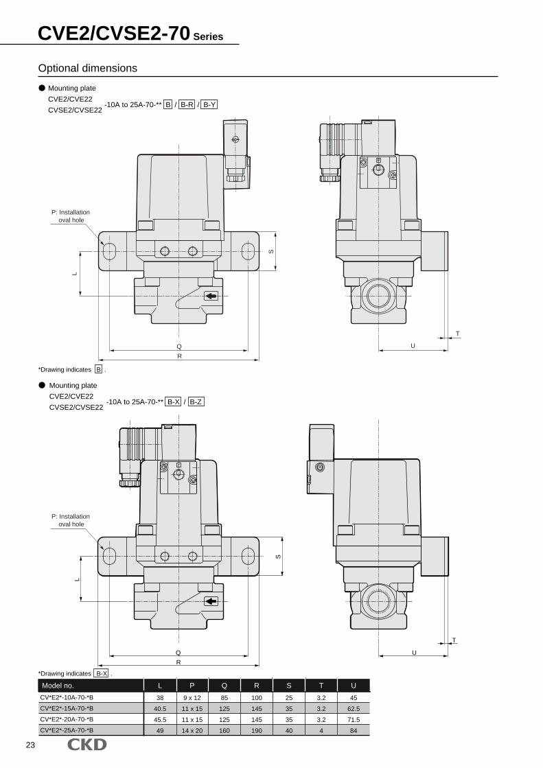
Optional dimensions
-10A to 25A-70-** B / B-R / B-Y
Mounting plate
CVE2/CVE22
CVSE2/CVSE22-10A to 25A-70-** B-X / B-Z
CV*E2*-10A-70-*B
CV*E2*-15A-70-*B
CV*E2*-20A-70-*B
CV*E2*-25A-70-*B
L
38
40.5
45.5
49
P
9 x 12
11 x 15
11 x 15
14 x 20
Q
85
125
125
160
R
100
145
145
190
S
25
35
35
40
T
3.2
3.2
3.2
4
U
45
62.5
71.5
84
Model no.
*Drawing indicates B .
*Drawing indicates B-X .
Mounting plate
CVE2/CVE22
CVSE2/CVSE22
Q
R
S
L
T
U
P: Installation oval hole
P: Installation oval hole
P
L
S
Q U
T
R
CVE2/CVSE2-70 Series

24
CVE2/CVSE2-70 SeriesOptional dimensions
Optional dimensions
3T3R
T type terminal box (G1/2)
T type terminal box with indicator light (G1/2)
CVSE2/CVSE22-*-70-*
P
15.5
3625
.5
4616
G1/2
(54.5)
(85.5)
35

25
Air operated 3 port valve for medium and high pressure(Coolant valve)
CVSE3-35/70 SeriesCVE3-35/70 Series
Directional type (C port pressurization only) Medium pressure 3.5MPa: Port size: Rc3/8 to Rc2 High pressure 7.0MPa: Port size: Rc3/8 to Rc1
Common specificationsDescriptions
Directional type (C port pressurization only)
Coolant, other non-corrosive fluids (*1)
500 or less
0 to 7.0 (Note that this differs with the type, so refer to the working pressure range in each model's specifications.)
-10 to 60 (no freezing)
-10 to 60
20 or less (with water pressure)
Free
0.25 to 0.5
Standard specifications
JIS symbol
Actuation
Working fluid
Fluid viscosity
Working pressure range
Fluid temperature
Ambient temperature
Valve seat leakage
Mounting attitude
Pilot air pressure
*1: Fluid that does not affect cast steel (nickel plating), stainless steel, nitrile rubber or fluoro rubber
Electric specifications100 VAC (50/60Hz)/110 VAC (60Hz), 200 VAC (50/60Hz)/220 VAC (60Hz) and 24 VDC
3.6 (50Hz) and 2.8 (60Hz)
11 (50Hz) and 9 (60Hz)
1.9 (50Hz) and 1.5 (60Hz)
2.0
B
At holding
At starting
AC
DC
Rated voltage (*2)
Heat proof class
Protective structure
(IEC standards 529)
With DIN terminal box (Pg9)
T type terminal box (G1/2)
IPX5
IPX5
Apparent power (VA)
Power consumption (W)
A B
C
Rc3/8
Rc1/2
Rc3/4
Rc1
Rc1 1/4
Rc1 1/2
Rc2
Rc3/8
Rc1/2
Rc3/4
Rc1
4.5
6
8
9
20
20
26
4.5
6
8
9
1.3
2.2
3.6
6
23
23
31
1.3
2.2
3.6
4.9
1
1.8
3
3.8
18.5
17
27
1
1.8
3
3.8
1.0
1.6
2.7
4.3
13.8
13.5
22.7
1.4
2.4
3.9
6.1
1.1
1.7
2.8
4.4
13.9
13.6
22.8
1.5
2.5
4.0
6.2
5.8 or equivalent
7.1 or equivalent
8.9 or equivalent
13.2 or equivalent
22 or equivalent
22 or equivalent
28.5 or equivalent
5.8 or equivalent
7.1 or equivalent
8.9 or equivalent
10.7 or equivalent
Individual specifications for 7.0MPa for 3.5MPa
CVE3/CVSE3-10A-35
CVE3/CVSE3-15A-35
CVE3/CVSE3-20A-35
CVE3/CVSE3-25A-35
CVE3/CVSE3-32A-35
CVE3/CVSE3-40A-35
CVE3/CVSE3-50A-35
CVE3/CVSE3-10A-70
CVE3/CVSE3-15A-70
CVE3/CVSE3-20A-70
CVE3/CVSE3-25A-70
Port sizeOrifice (mm) Cv flow factor Weight (kg)Pilot
Port size
0 to 3.5
RC 1/8
0 to 7.0
7
14
Workingpressure
range(MPa)
Withstandingpressure (withwater pressure)
(MPa)NC side NO side NC side CVE3 CVSE3NO sideDescriptionsModel no.
P A B
C
Y
CVE3 (air operated type)
CVSE3 (with solenoid valve)
mm2/sMPa
cm3/min
MPa
*2: The allowable voltage range should be within 10% of rated voltage.

26
CVE3/CVSE3-35/70 SeriesHow to order
undefined
CVE3 20A
CVSE3
0
0
B
S
70
13515A 2G
A Port size
B Working pressure range
D Coil
E Otheroptions
F Assemblydirection
G Voltage
C Body/sealant combination
How to order
Model: CVSE3 : with solenoid valve (3 port)G Port size : Rc1/2Working pressure range : 0 to 3.5MPaBody/sealant combination
: Body-cast iron (plating) and sealant-nitrile rubberCoil : With DIN terminal box (Pg9)Other options : With surge suppressorG Assembly direction : No optionG Voltage : 100 VAC (50/60Hz) and 110 VAC (60Hz)
<Example of model number>
CVSE3-15A-35-02GS-1
A
B
C
D
E
F
G
E
E
*1, *2*3, *4
*5
CVE3
CVSE3
Model no.
Air operated type(3 port)
With solenoid valve(3 port)
*1: Mounting plate (B in ) is attached. This plate can be installed on port size 10A, 15A, 20A or 25A.
*2: Indicate SB in if both surge suppressor and mounting plate are selected.*3: A surge suppressor is assembled in the terminal box.*4: Manual override (non-locking) specifications are standard for
solenoid valve.*5: The assembly direction option cannot be selected for the air-
operated type or 32A to 50A.*6: Facing to IN port right and viewed from the top, turning angle to
clockwise is indicated.
Air operated type
With solenoid valve CVE3
Mediumpressure(3.5MPa)
Highpressure(7.0MPa)
Mediumpressure(3.5MPa)
Highpressure(7.0MPa)
CVSE3
Port sizeA
1
2
3
100 VAC (50/60Hz)
110 VAC (60Hz)
200 VAC (50/60Hz)
220 VAC (60Hz)
24 VDC
VoltageG
2G
2H
3T
3R
With DIN terminal box (Pg9)
With DIN terminal box with indicator light (Pg9)
T type terminal box (G1/2)
With T type terminal box with indicator light (G1/2)
CoilD
Blank
S
B
No option
With surge suppressor
Mounting plate
Other optionsE
35
70
0 to 3.5MPa
0 to 7.0MPa
Working pressure rangeB
0
B
Standard
Option
Body
Cast iron (plating)
Cast iron (plating)
Sealant
Nitrile rubber
Fluoro rubber
Body/sealant combinationC
Symbol Descriptions
10A
15A
20A
25A
32A
40A
50A
Rc3/8
Rc1/2
Rc3/4
Rc1
Rc1 1/4
Rc1 1/2
Rc2
Model no.
Blank
X
Y
Z
R
No option
Cylinder guard 90° rotation
Cylinder guard 180° rotation
Cylinder guard 270° rotation
Coil 180° reverse rotation <with solenoid valve>
Assembly directionF
Refer to the following diagram for the layout drawing.
Assembly directionF
CVSE3 <with solenoid valve> *6Symbol
Direction
Arrangement
Blank (standard)
Without rotation
X
Cylinder guard 90° rotation
Y
Cylinder guard 180° rotation
Z
Cylinder guard 270° rotation
R
Coil reverse rotation

Internal structure and parts list
No.
1
2
3
4
5
6
7
8
9
10
Parts name
Cylinder guard
Piston
Adaptor
Valve stem
Body
NO body
Pilot solenoid valve
Spring
Rod packing seal
NC valve seat
Material
ADC12
A2017
SUS303
SUS420J2
FCD450
SUS303
-
SWP
NBR (FKM)
SUS303
Aluminum alloy die-casting
Aluminum
Stainless steel
Stainless steel
Cast iron (plating)
Stainless steel
-
Piano wire
Stainless steel
Nitrile rubber(Fluoro rubber)
No.
1
2
3
4
5
6
7
8
9
10
Parts name
Cylinder guard
Piston
Adaptor
Valve stem
Body
NO body
Pilot solenoid valve
Spring
Rod packing seal
NC valve seat
Material
AC7A
A2017
SUS303
SUS420J2
FCD450
SUS303
-
SWP
NBR (FKM)
SUS303
Aluminum casting
Aluminum
Stainless steel
Stainless steel
Cast iron (plating)
Stainless steel
Piano wire
Stainless steel
Nitrile rubber(Fluoro rubber)
CVSE3-10A to 25A-35
CVSE3-32A/40A/50A-35
Port A
Port B
Port C
Port A Port C
Port B
1
2
3
4
5
6
1
7
8
9
10
2
3
4
5
6
7
8
9
10
27
CVSE3-35/70 Series
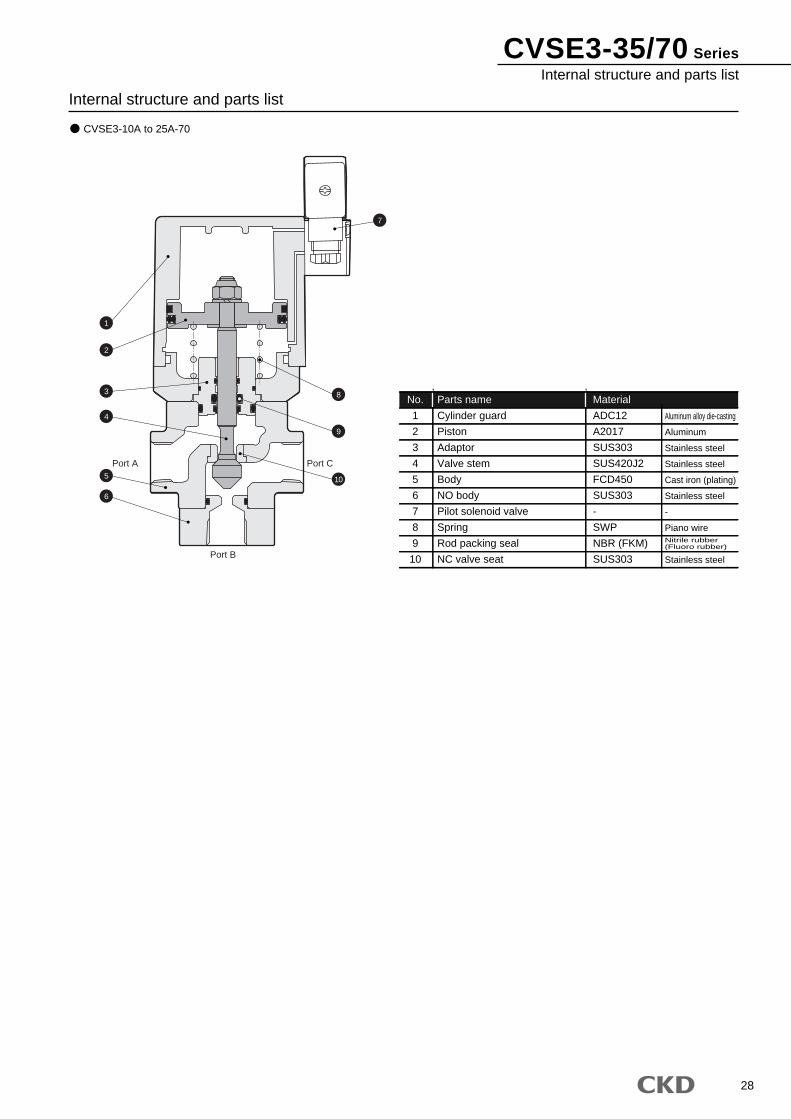
Internal structure and parts list
No.
1
2
3
4
5
6
7
8
9
10
Parts name
Cylinder guard
Piston
Adaptor
Valve stem
Body
NO body
Pilot solenoid valve
Spring
Rod packing seal
NC valve seat
Material
ADC12
A2017
SUS303
SUS420J2
FCD450
SUS303
-
SWP
NBR (FKM)
SUS303
Aluminum alloy die-casting
Aluminum
Stainless steel
Stainless steel
Cast iron (plating)
Stainless steel
-
Piano wire
Stainless steel
Nitrile rubber(Fluoro rubber)
CVSE3-10A to 25A-70
Port A Port C
Port B
8
9
10
7
1
2
3
4
5
6
CVSE3-35/70 SeriesInternal structure and parts list
28

Dimensions
CVSE3-10A-35-*2G
CVSE3-15A-35-*2G
CVSE3-20A-35-*2G
CVSE3-25A-35-*2G
A
60
80
90
110
B
28
32
40
48
C
35.5
43.5
52
61
D
69
81.5
102
122.5
E
149.5
170
199
228.5
F
53
63
77
95
G
Rc3/8
Rc1/2
Rc3/4
Rc1
K
M6 thread length 9
M6 thread length 9
M8 thread length 10
M8 thread length 10
L
59
65.5
79.5
91
M
20
20
25
25
N
53
57.5
64.5
72.5
Model no.
CVSE3-32A-35-*2G
CVSE3-40A-35-*2G
CVSE3-50A-35-*2G
A
120
120
140
B
61
61
76
CA
118
118
135
CC
63
63
75
D
264.5
264.5
314
E
309.5
309.5
366
F
145
145
176
G
Rc1 1/4
Rc1 1/2
Rc2
H J
M12 depth 30
M12 depth 30
M16 depth 35
K
90
90
96
N
103
103
123
Model no.
With DIN terminal box (Pg9)CVSE3-10A to 25A-35-*2G
With DIN terminal box (Pg9)CVSE3-32A/40A/50A-35-*2G
109
109
124
A
C
P
B
A C
B
*Drawing indicates no optional assembly direction.
Pg9
CD
F
B
A
E
N22
18
44
53
44.5 (3
8)
15.5
M
LApplicable cable2 x 2-K
3-G
Non-locking manual
Rc1/8
M5Exhaust port
N
A
CC
CA
K
D
E
F
B
53
18
(38)
15.5
22
Pg9
Rc1/8Non-locking
M5 depth 4.5Exhaust port
44
44.5
2-J
3-G
(O.D. 4.5 to 7)
H
Applicable cable(O.D. 4.5 to 7)
29
CVSE3-35/70 Series

30
CVSE3-35/70 SeriesDimensions
Dimensions
CVSE3-10A-70-*2G
CVSE3-15A-70-*2G
CVSE3-20A-70-*2G
CVSE3-25A-70-*2G
A
60
80
90
110
B
28
32
40
48
C
35.5
43.5
52
61
D
92.5
114
136.5
149.5
E
173
202.5
233.5
255.5
F
63
77
95
113
G
Rc3/8
Rc1/2
Rc3/4
Rc1
K
M6 thread length 9
M8 thread length 10
M8 thread length 10
M12 thread length 14
L
73.5
84
97.5
110
M
20
25
25
45
N
57.5
64.5
72.5
82.5
Model no.
With DIN terminal box (Pg9)CVSE3-10A to 25A-70-*2G
A C
B
*Drawing indicates no optional assembly direction.
Pg9
Applicable cable
N
A
B
F
CD E
22
18
44
53
44.5
(38
)
15.5
2 x 2-K
M
L
Non-locking manual
Rc1/8
3-G
M5Exhaust port
(O.D. 4.5 to 7)
Refer to page 35 for coil option/mounting plate.
Optional dimensions

31
CVE3-35/70 Series
Internal structure and parts list
CVE3-10A to 25A-35
CVE3-32A/40A/50A-35
No.
1
2
3
4
5
6
7
8
9
Parts name
Cylinder guard
Piston
Adaptor
Valve stem
Body
NO body
Spring
Rod packing seal
NC valve seat
Material
ADC12
A2017
SUS303
SUS420J2
FCD450
SUS303
SWP
NBR (FKM)
SUS303
Aluminum alloy die-casting
Aluminum
Stainless steel
Stainless steel
Cast iron (plating)
Stainless steel
Piano wire
Stainless steel
Nitrile rubber(Fluoro rubber)
No.
1
2
3
4
5
6
7
8
9
Parts name
Cylinder guard
Piston
Adaptor
Valve stem
Body
NO body
Spring
Rod packing seal
NC valve seat
Material
AC7A
A2017
SUS303
SUS420J2
FCD450
SUS303
SWP
NBR (FKM)
SUS303
Aluminum casting
Aluminum
Stainless steel
Stainless steel
Cast iron
Stainless steel
Piano wire
Stainless steel
Nitrile rubber(Fluoro rubber)
Port A
Port B
Port C
Port A Port C
Port B
1
7
8
9
7
8
9
2
3
4
5
6
1
2
3
4
5
6

32
CVE3-35/70 SeriesInternal structure and parts list
Internal structure and parts list
CVE3-10A to 25A-70
No.
1
2
3
4
5
6
7
8
9
Parts name
Cylinder guard
Piston
Adaptor
Valve stem
Body
NO body
Spring
Rod packing seal
NC valve seat
Material
ADC12
A2017
SUS303
SUS420J2
FCD450
SUS303
SWP
NBR (FKM)
SUS303
Aluminum alloy die-casting
Aluminum
Stainless steel
Stainless steel
Cast iron
Stainless steel
Piano wire
Stainless steel
Nitrile rubber(Fluoro rubber)
Port A Port C
Port B
7
8
9
1
2
3
4
5
6

CVE3-35/70 Series
Dimensions
CVE3-10A-35-*
CVE3-15A-35-*
CVE3-20A-35-*
CVE3-25A-35-*
A
60
80
90
110
B
28
32
40
48
C
35.5
43.5
52
61
D
65
77.5
98
118.5
E
118.5
139
168
197.5
F
53
63
77
95
G
Rc3/8
Rc1/2
Rc3/4
Rc1
K
M6 thread length 9
M6 thread length 9
M8 thread length 10
M8 thread length 10
L
59
65.5
79.5
91
M
20
20
25
25
N
41.5
46
53
61
Model no.
CVE3-32A-35-*
CVE3-40A-35-*
CVE3-50A-35-*
A
120
120
140
B
61
61
76
CA
118
118
135
CC
63
63
75
D
260.5
260.5
310
E
301
301
366
F
145
145
176
G
Rc1 1/4
Rc1 1/2
Rc2
H J
M12 depth 30
M12 depth 30
M16 depth 35
K
90
90
96
N
91
91
111
Model no.
CVE3-10A to 25A-35-**
CVE3-32A/40A/50A-35-**
109
109
124
A
C
B
A C
B
14.6N
CD
10
E
F
B
A
M
L
2 x 2-K
2-Rc1/8
G
A
CC
CA
K
F
D
E
10
14.6 2-Rc1/8N
2-J
B3-G
H
33

34
Dimensions
CVE3-10A-70-*
CVE3-15A-70-*
CVE3-20A-70-*
CVE3-25A-70-*
A
60
80
90
110
B
28
32
40
48
C
35.5
43.5
52
61
D
88.5
110
132.5
145.5
E
142
171.5
202.5
224.5
F
63
77
95
113
G
Rc3/8
Rc1/2
Rc3/4
Rc1
K
M6 thread length 9
M8 thread length 10
M8 thread length 10
M12 thread length 14
L
73.5
84
97.5
110
M
20
25
25
45
N
46
53
61
71
Model no.
CVE3-10A to 25A-70-**
A C
B
N
A
14.6
BF
CD
10
E
2 x 2-K
M
L
2-Rc1/8
3-G
Refer to page 35 for mounting plate.
Optional dimensions
CVE3-35/70 SeriesDimensions

Optional dimensions
3T3R
CV*E3-10A-35-*B
CV*E3-15A-35-*B
CV*E3-20A-35-*B
CV*E3-25A-35-*B
CV*E3-10A-70-*B
CV*E3-15A-70-*B
CV*E3-20A-70-*B
CV*E3-25A-70-*B
L
59
65.5
79.5
91
73.5
84
97.5
110
P
9 x 12
9 x 12
11 x 15
11 x 15
9 x 12
11 x 15
11 x 15
14 x 20
Q
85
85
125
125
85
125
125
160
R
100
100
145
145
100
145
145
190
S
25
25
35
35
25
35
35
40
T
3.2
3.2
3.2
3.2
3.2
3.2
3.2
4
U
40
45
62.5
71.5
45
62.5
71.5
84
Model no.
Mounting plate
CVE3/CVSE3-10A to 25A-35/70-** B / B-R / B-Y
Mounting plate
CVE3/CVSE3-10A to 25A-35/70-** B-X / B-Z
T type terminal box (G1/2)
T type terminal box with indicator light (G1/2)
CVSE3-*-35/70-*
Refer to page 24 for optional dimensions.
A
A
*Drawing indicates B .
*Drawing indicates B-X .
QR
S
L
TU
P: Installation oval hole
P: Installation oval hole
P
QU
T
L
S
R
35
CVE3/CVSE3-35/70 Series

36
Options for interchanging old/new models Old/new complete interchangeable mounting plate (air operated type)
Compatible mounting plates with old (CV2) installation plate type are available.
Series:
CVE2 05 0 R2 B215A
A Actuation
B Port sizeAir operatedtype
How to order
D Body/sealantMaterial combination
F Assemblydirection
E Other optionsC Working pressureRange
B
B2
Mounting plate
Old products compatible mounting plate
Other optionsE
CVSE2 05 02 2G15A
A Actuation
B Port sizeWith solenoidvalve
D Body/sealantMaterial combination
H VoltageF Other options
E Coil G Assembly direction
R 1B2
C Working pressureRange
B
B2
Mounting plate
Old products compatible mounting plate
Other optionsF
Comparison of new and old products (air operated type)Old type
Symbol
Direction
Arrangement
B
-
New typeSymbol
Direction
Arrangement
B2-R
Mounting plate, reverse
Comparison of new and old products (with solenoid valve)Old type
Symbol
Direction
Arrangement
B
-
New typeSymbol
Direction
Arrangement
B2-R
Coil reverse,mounting plate reverse
New typeSymbol
Direction
Arrangement
B2-Y
Cylinder guard: 180° rotation, mounting plate: reverse
*Mounting plate is assembled in the 180° opposite side, if "B2-R" is selected.
*Mounting plate is assembled in the 180° opposite side, if "B2-Y" is selected.
or
CVE2 (2)-05/10/16/30/70CVSE2 (2)-05/10/16/30/70CVE3/CVSE3-35/70* Refer to How to order explanations on pages 3, 13, 20, and 26 for details on models for which the mounting plate option is selected.
indicates flow path direction, while indicates pilot ports IN.

37
Dimensions
CVSE2 (2)-*-70
3 port valve
CVSE3-*-35/70
CV*E2 (2)-15A-05/10
CV*E2 (2)-20A-05/10
CV*E2 (2)-25A-05/10
CV*E2 (2)-10A-16
CV*E2 (2)-15A-16
CV*E2 (2)-20A-16
CV*E2 (2)-10A-30
CV*E2 (2)-15A-30
P
100
110
120
110
110
120
110
120
Q
70
75
85
75
75
85
75
85
45
50
55
50
50
55
50
55
2.3
3.2
3.2
3.2
3.2
3.2
3.2
3.2
TR S
30
40
45
40
40
45
40
45
Model no.
CV*E3-10A-35
CV*E3-10A-70
L
56.5
71
P
9 x 12
9 x 12
85
85
100
100
SQ R
25
25
T
3.2
3.2
U
40
45
Model no.
CV*E2 (2)-10A-70
L P
35.5
Q
9 x 12 10085 25
UR S T
453.2
Model no.
*The drawing indicates an example when solenoid valve is installed. *The drawing indicates an example when solenoid valve is installed.
*The drawing indicates an example when solenoid valve is installed.
*L dimensions of 3 port valves is for oval hole.
2 port valve
CVSE2 (2)-*-05/10/16/30
P
P: Installation oval hole
Q UT
RL
S
P
Q
S
T
R
L
S
QU
T
A
R
P
CVE/CVSE Series

38
Old/new replacement option Old/new pilot port size conversion connectorConversion connectors are available to correspond with differences in the old and new pilot port sizes.
Series:
How to orderCVSE2-P-CONNECTOR-D4-162163
Dimensions
Introducing custom order parts
CVSE2 (2), CVE2 (2)
CVSE3, CVE3
A pilot solenoid valve is installed on the valve top.Series: CVSE2 (2), CVSE3
Consult with CKD, your nearest sales office, for "How to order: model no."
A valve open/close detection switch is installed on the coolant valve. 2 types are available in open and close signal detection switch of valve, both sides installation.
Series: CVE2 (2), CVSE2 (2)
CVE3, CVSE3
Consult with CKD, your nearest sales office, for "How to order: model no."
Rc1/4
R 1/8
18Hexagon head 2127

2007.5.ACC●Specifications are subject to change without notice.
The goods and their replicas, or the technology and software in this catalog are subject to complementary export regulations by Foreign Exchange and Foreign Trade Law of Japan.If the goods and their replicas, or the technology and software in this catalog are to be exported, laws require the exporter to make sure they will never be used for the development or the manufacture of weapons for mass destruction.
CKD CORPORATION TAIWAN BRANCH
M-CKD PRECISION SDN.BHD.CKD USA CORPORATION
CKD UK OFFICE
CKD CORPORATION EUROPE BRANCH
CKD BELGIUM OFFICE
CKD CO.,LTD.,o.s. CZECH OFFICE
CKD KOREA CORPORATION
CKD THAI CORPORATION LTD.
CKD SINGAPORE PTE. LTD.
●WUXI OFFICE ●NANJING OFFICE ●HANGZHOU OFFICE ●WUHAN OFFICE ●QINGDAO OFFICE
●SUZHOU OFFICE ●BEJING OFFICE ●TIANJING OFFICE ●CHANG CHUN OFFICE ●DALIAN OFFICE
●SHENYANG OFFICE ●XIAN OFFICE ●CHONGQING OFFICE ●CHENGDU OFFICE ●GUANGZHOU OFFICE ●SHENZHEN OFFICE
●CINCINNATI OFFICE ●SAN ANTONIO OFFICE ●SAN JOSE OFFICE
●JOHOR BAHRU OFFICE ●MELAKA OFFICE ●PENANG OFFICE
●LAEMCHABANG OFFICE ●NAVANAKORN OFFICE ●RAYONG OFFICE ●LAMPHUN OFFICE ●KORAT OFFICE ●AMATANAKORN OFFICE
CKD(SHANGHAI) CORPORATION
:Distributors
●HWASEONG OFFICE
CKD CANADA
□ OVERSEAS DPT. SALES DIV. 2-250 Ouji Komaki, Aichi 485-8551, Japan □ PHONE +81-(0)568-74-1338 FAX +81-(0)568-77-3461
Website http://www.ckd.co.jp/
U.S.A CKD USA CORPORATION ● HEADQUARTERS 4080 Winnetka Avenue, Rolling Meadows, IL 60008 USA PHONE +1-847-368-0539 FAX +1-847-788-0575
EUROPE CKD EUROPE BRANCH De Fruittuinen 28 Hoofddorp 2132NZ The Netherlands PHONE +31-(0)23-5541490 FAX +31-(0)23-5541491
Malaysia M-CKD PRECISION SDN.BHD. ● HEADQUARTERS Lot No.6,Jalan Modal 23/2, Seksyen 23, Kawasan, MIEL, Fasa 8, 40300 Shah Alam,Selangor Darul Ehsan, Malaysia PHONE +60-(0)3-5541-1468 FAX +60-(0)3-5541-1533
Thailand CKD THAI CORPORATION LTD. ● SALES HEADQUARTERS-BANGKOK OFFICE Suwan Tower, 14/1 Soi Saladaeng 1, North Sathorn Rd., Bangrak, Bangkok 10500 Thailand PHONE +66-(0)2-267-6300 FAX +66-(0)2-267-6305
Singapore CKD SINGAPORE PTE LTD. 705 Sims Drive #03-01/02, Shun Li Industrial Complex, 387384 Singapore PHONE +65-6744-2623 FAX +65-6744-2486
Taiwan CKD CORPORATION TAIWAN BRANCH Rm.1405, 14F, No.96, Sec.2, Chung Shan N.Rd., Taipei, Taiwan, R.O.C. PHONE +886-(0)2-2523-0374 FAX +886-(0)2-2523-5081
China CKD (SHANGHAI) CORPORATION ● SALES HEADQUARTERS / SHANGHAI OFFICE Room 1903, 333 Jiujiang Road, Shanghai, 200001, China PHONE +86-(0)21-63602277 FAX +86-(0)21-63511661
Korea CKD KOREA CORPORATION Room No.1105, 11th FL, The Korea Teachers Pention B/L. 27-2, Yoido-Dong, Youngdeungpo-Gu, Seoul, 150-742, Korea PHONE +82-(0)2-783-5201~5203 FAX +82-(0)2-783-5204