new stone shells: design and robotic fabrication
TRANSCRIPT

Proceedings of the International Association for Shell and Spatial Structures (IASS) Symposium 2009, Valencia Evolution and Trends in Design, Analysis and Construction of Shell and Spatial Structures
28 September – 2 October 2009, Universidad Politecnica de Valencia, Spain Alberto DOMINGO and Carlos LAZARO (eds.)
New stone shells: design and robotic fabrication Martin BECHTHOLD*
*Harvard Graduate School of Design
48 Quincy Street, Cambridge, MA 02138 [email protected]
Abstract The research explores the design and analysis of a thin marble shell that incorporates the latest developments in fabrication technology and computational analysis. Natural stone, one of the oldest and most traditional building materials, is used in innovative ways by manipulating it with a 6-axis robotic waterjet. The research studies techniques for the robotic perforation and surfacing of natural stone, with a particular focus on marble. The work was conducted in collaboration with Monica Ponce de Leon and Wes McGee at the Harvard Graduate School of Design (GSD). Small tests panels explore how transparency and translucency of stone can be generated through robotic waterjet cutting. A prototypical stone shell is designed to further explore the design potential encountered in the small test pieces. The shell is post-tensioned and stiffened with metal stiffeners. Finite-element analysis (FEA) serves as a primary technique to conduct a detailed structural analysis of the shell. Keywords: stone shell, post-tensioning, robotic fabrication, waterjet cutting, parametric design, shell buckling, finite-element analysis.
1. A New Age of Stone? Natural stone is one of mankind’s oldest building materials. Apart from its use as a structural material, stone is used predominantly as wall cladding or as floor tile. Stone production techniques are relying extensively on computer-numerically controlled (CNC) machines such as saws, mills, and 3-axis waterjets, but the design of stone surfaces has not progressed much despite these new fabrication technologies. The research sets out to explore new opportunities for design with natural stone by using a new type of fabrication equipment – a six-axis robotic waterjet cutter. More specifically, the project studies how surface manipulations and perforations of stone can be used to manipulate light effects. Recent examples of the use of thin stone as a translucent material include, among others, Yale University’s Beinecke Rare Book and Manuscript Library (Skidmore, Owings & Merrill, New Haven, 1963), the Pilar and Joan Miró Mallorca Foundation (Rafael Moneo, 1992), and the cathedral of Notre-Dame de la Treille in Lille, France (facade design by Peter Rice, completed in 1999). In all of these examples feature thin stone slabs that are
1780
Proceedings of the International Association for Shell and Spatial Structures (IASS) Symposium 2009, Valencia Evolution and Trends in Design, Analysis and Construction of Shell and Spatial Structures
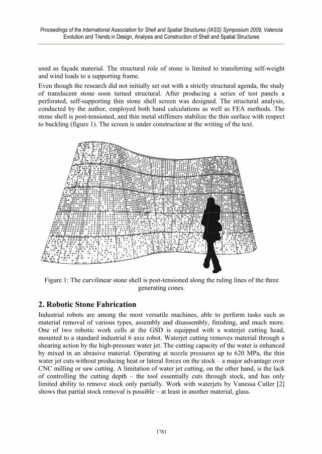
used as façade material. The structural role of stone is limited to transferring self-weight and wind loads to a supporting frame. Even though the research did not initially set out with a strictly structural agenda, the study of translucent stone soon turned structural. After producing a series of test panels a perforated, self-supporting thin stone shell screen was designed. The structural analysis, conducted by the author, employed both hand calculations as well as FEA methods. The stone shell is post-tensioned, and thin metal stiffeners stabilize the thin surface with respect to buckling (figure 1). The screen is under construction at the writing of the text.
Figure 1: The curvilinear stone shell is post-tensioned along the ruling lines of the three
generating cones.
2. Robotic Stone Fabrication Industrial robots are among the most versatile machines, able to perform tasks such as material removal of various types, assembly and disassembly, finishing, and much more. One of two robotic work cells at the GSD is equipped with a waterjet cutting head, mounted to a standard industrial 6 axis robot. Waterjet cutting removes material through a shearing action by the high-pressure water jet. The cutting capacity of the water is enhanced by mixed in an abrasive material. Operating at nozzle pressures up to 620 MPa, the thin water jet cuts without producing heat or lateral forces on the stock – a major advantage over CNC milling or saw cutting. A limitation of water jet cutting, on the other hand, is the lack of controlling the cutting depth – the tool essentially cuts through stock, and has only limited ability to remove stock only partially. Work with waterjets by Vanessa Cutler [2] shows that partial stock removal is possible – at least in another material, glass.
1781

Proceedings of the International Association for Shell and Spatial Structures (IASS) Symposium 2009, Valencia Evolution and Trends in Design, Analysis and Construction of Shell and Spatial Structures
Initial research produced a wide variety of test pieces that explore cutting parameters and innovative ways to manipulate stone using a robotic waterjet. Early experiments tested cutting parameters such as feed rate and water pressure. By removing part of the stone, but not cutting through the stone slabs, the material thickness could be sufficiently reduced in order to allow light to penetrate the stone. Figure 2 shows some of the shaping experiments. It soon became clear that the lack of control in the shaping of stone without cutting through was a slow and comparatively inefficient process, and not well suited to the use of waterjet cutting technology. Cutting through, in comparison, is fast and efficient, and a number of experiments in perforating stone suggested the pursuit of this approach in the exploration of the chosen theme of light and translucency. Perforated stone slabs were eventually incorporated into the design of the prototypical stone shell.
Figure 2: Marble test panels. Left: perforation pattern. Right: surfacing stone.
3. Shell Design There is relatively little precedent for the design of thin stone shells. Traditional stone vaults feature relatively deep stone surfaces compared to their spans, thus differ significantly from a shell. Eladio Dieste’s tile shells show impressive structural lightness by combining pre-stressing with the use of compression-only blocks and tiles. His approach to pre-stressing is to designate distinct layers – one layer of compression material – tile or block – and a second layer of pre-stressing members embedded in a cementitious mortar. Both layers are connected through mechanically hooking the pre-stressing cables into the joints between the blocks. All of Dieste’s pre-stressed shells have a visible tile surface only on one side, whereas the others side, usually the upper side for shell roofs, is a concrete surface [1]. The proposed vertical stone shell was to exhibit the materiality of stone on both sides. To maintain extreme thinness the post-tensioning cables were to be integrated into the stone surface by embedding the cables in the joints between stone slabs. For the proposed shell the embedment of the post-tensioning cables, along with the limitations of stone sizes, leads to a design that is based on ruled surface geometry. The straight cable trajectory was visually disguised by creating undulating cuts along the adjoining stone edges with the multi-axis waterjet head.
1782

Proceedings of the International Association for Shell and Spatial Structures (IASS) Symposium 2009, Valencia Evolution and Trends in Design, Analysis and Construction of Shell and Spatial Structures
Another consideration of the shell design addressed the relationship between the size of the stone slabs and the curvature of the shell. For visual reasons large stone slabs were desirable, but the resulting tessellation through the approximation of a curved form through flat panels was visually problematic. As a result shell designs with a relatively mild curvature were considered that were aesthetically pleasing, while allowing for construction with relatively large flat stone slabs. The final shape consisted of three cones tapering in opposite directions (Figure 3).
Figure 3: Drawings of the stone screen.
Cantilevering shells with shallow curvatures have a more pronounced tendency for buckling. In response to this issue metal stiffeners were introduced in the horizontal stone joints. Stone and metal profiles are equally compressed through the post-tensioning force of the cables, and are otherwise connected with shear dowels that prevent any out-of place displacement of the stone. Post-tensioning was necessary only for lateral loads of wind and seismic forces. Figure 4 shows the basic structural diagram of the screen.
1783

Proceedings of the International Association for Shell and Spatial Structures (IASS) Symposium 2009, Valencia Evolution and Trends in Design, Analysis and Construction of Shell and Spatial Structures
Figure 4: Post-tension forces are applied along the ruling lines of the three cones. The
forces were prescribed such that any possible tension from lateral loading was completely eliminated. The lateral force direction shown was the governing design case.
4. Analysis Procedure The structural design of the stone shell employed material properties that were determined with load tests of marble specimen. A simple, post-tensioned stone shell was initially analyzed with hand calculations, and the results duplicated and verified with an FEA of the same design. After finding very close correlation of bending stresses the design of the actual shell form proceeded using the same FEA parameters.
4.1. Material Tests Prior to conducting the computational FE analysis material properties of the Carrara Bianca marble were tested in the GSD’s testing lab. The material properties of marble are governed by ASTM C 503 – 08. According to the standard, the density should be 2595 kg/m3, compressive strength should be 52 MPa, and both modulus of rupture and flexural strength should be a minimum of 7 MPa. To confirm the strength values a test of several specimen was conducted, as is recommended in ASTM C 508-08.
1784
Proceedings of the International Association for Shell and Spatial Structures (IASS) Symposium 2009, Valencia Evolution and Trends in Design, Analysis and Construction of Shell and Spatial Structures
Four specimens were tested in the GSD’s lab in axial compression, and three specimens were subject to a three-point bend test. Compression specimen were 50 x 50 mm (29 mm thick), and bending specimens were 101 x 406 mm with a clear span during the test of 305 mm. The compression specimen showed a maximum compressive strength of 83 MPa, surpassing ASTM standard significantly. The bend specimen failed at a bending stress of approximately 8.3 MPa, also exceeding ASTM C 508-08. Based on strain measurements during the compression tests the compression modulus was calculated to be 483 MPa. Due to problems during the test the strain measurements were likely to be approximate, and the modulus value is uncertain. A literature review on this question showed that Italian standards for Bianco Carrara Marble indicate a minimum modulus of 61363 MPa. The American Civil Engineer’s Pocket Books gives 55160 MPa as modulus of elasticity of marble (this value is generic and not specific for Carrara Bianco). It is very likely that the material is much stiffer than 483 MPa, but all FEA calculations were done using that number, thus erring significantly on the safe side.
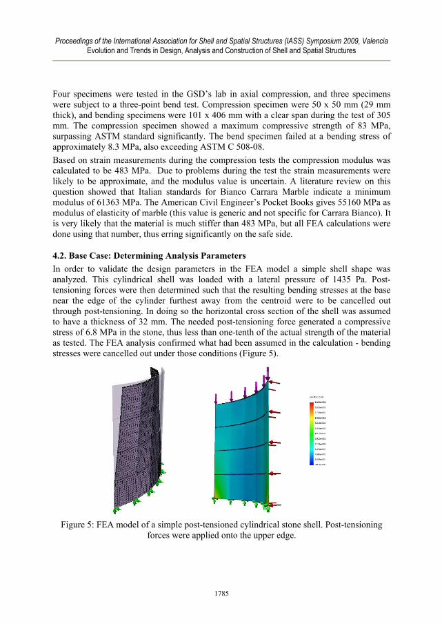
4.2. Base Case: Determining Analysis Parameters In order to validate the design parameters in the FEA model a simple shell shape was analyzed. This cylindrical shell was loaded with a lateral pressure of 1435 Pa. Post-tensioning forces were then determined such that the resulting bending stresses at the base near the edge of the cylinder furthest away from the centroid were to be cancelled out through post-tensioning. In doing so the horizontal cross section of the shell was assumed to have a thickness of 32 mm. The needed post-tensioning force generated a compressive stress of 6.8 MPa in the stone, thus less than one-tenth of the actual strength of the material as tested. The FEA analysis confirmed what had been assumed in the calculation - bending stresses were cancelled out under those conditions (Figure 5).
Figure 5: FEA model of a simple post-tensioned cylindrical stone shell. Post-tensioning
forces were applied onto the upper edge.
1785

Proceedings of the International Association for Shell and Spatial Structures (IASS) Symposium 2009, Valencia Evolution and Trends in Design, Analysis and Construction of Shell and Spatial Structures
4.3. Final Analysis The site for the stone shell is well protected from the wind, and according to Massachusetts building codes a pressure of 670 Pa had to be assumed acting from each of the four principle directions. The maximum resulting lateral force is 10.6 KN from wind. For seismic loads a quasi-static analysis showed maximum base shears of 4.8 KN, so wind loads govern. For pure gravity loads the wall is stable through its own self-weight. In order to determine the required post-tensioning force the maximum wind load was applied according to the direction indicated in figure 4. The post-tensioning forces were determined assuming that a fully post-tensioned shell was desired, and considering the wall as a wide cantilevering beam with a moment of inertia at the base of 1058 cm4. This simplifying analysis served only to determine the post-tensioning force using well known bending equations f = m c / I. C, the distance from the neutral axis to the outermost fiber, is 61.2 cm at midpoint and 37.7 cm for the outer cone segments. The cross-sectional area at the base is 2118 cm2. For a wind load of 670 Pa from either side the maximum bending moment at the base from wind equals 15.4 KN-m. The shell leans slightly to one side, with centroids between the overall shell and the projection at its base offset by 20.1 cm. When adding the resulting moment from self-weight of 2.9 KN-m the maximum moment at the base is 18.3 KN-m. The post-tensioning force required to cancel out the associated bending stresses (in tension) of 0.4MPa is 88.9 KN. The outermost edges of the shell are most susceptible to buckling, so the post-tensioning force is reduced here. These edges are also close to the neutral plane, and consequently have only a minor effect on the stiffness of the wall with respect to lateral loads. The post-tensioning force is distributed over 17 internal and 2 edge post-tensioning rods. A force of 2.4 KN is applied onto the edge rods, and the full 4.9 KN force is applied over for remaining internal rods. The maximum theoretical compressive stress from post-tensioning and self weight is 0.83 MPa, hence far below material failure limits for marble as determined in the tests. The post-tensioning rods are 4.7 mm stainless steel (Figure 6).
Figure 6: Displacements for governing load case.
1786

Proceedings of the International Association for Shell and Spatial Structures (IASS) Symposium 2009, Valencia Evolution and Trends in Design, Analysis and Construction of Shell and Spatial Structures
The FEA uses a 4-point shell mesh element, and was conducted using CosmosWorks 2007. The governing load case for stresses and maximum deflections is self-weight combined with wind load as shown in figure 4. Van Mieses stresses (combined bending and membrane) are generally small and reach a maximum of 2 MPa, thus well below the material strength. Deflections reach a maximum with 22 mm at the upper edge in the middle The FEA did not take the perforations into account, since modeling several thousand holes in the surface was computationally prohibitive. Instead, a detailed study of three typical perforated panels was conducted to understand the stress increases that would result from the perforations. Figure 7 shows the panels chosen for the study.
Figure 7: Left: Location of selected panels to study the effect of perforations on stresses. Right: Detailed study of stresses in one stone panel.
The panels with the largest combined bending and membrane stresses, located in the upper right hand corner, show (non-perforated) stresses of 2 MPa. The FEA study of the panels shows stress concentrations in the order of 7 MPa, thus still far below the material strength limits A concern in the design was the risk of buckling of the stone shell due to its relatively mild curvature and the underlying ruling geometry. A study of buckling with a pure stone shell, without metal stiffeners, showed a buckling load factor of 1.24 for the same governing load case as shown in figure 4 – self-weight, post-tensioning force, and wind load on concave face of middle cone shape. Considering the uncertainties of the experimental construction it was decided to add the horizontal metal stiffeners to ensure a larger safety margin. Adding aluminum stiffeners from A6061 alloy increases the load factor for the same load case to 2.2 with (Figure 8).
1787

Proceedings of the International Association for Shell and Spatial Structures (IASS) Symposium 2009, Valencia Evolution and Trends in Design, Analysis and Construction of Shell and Spatial Structures
Figure 8: Buckling study with scaled displacements. Left: Stone shell without stiffeners,
load factor 1.24. Right: stone shell with metal stiffeners, load factor 2.2.
In both cases buckling would occur in the lower area of the outermost edge. This behavior is quite typical of shells that frequently show vulnerability at the edges. In the case of the proposed design the lower shell areas feature larger forces as self-weight and post-tensioning force combine. The structural depth of the metal stiffeners changes from 29 mm to 75 mm over the length of the undulating surface. The horizontal stiffeners are also useful for other purposes. They serve as a guide during construction, providing a form reference for the assembly process. The stiffeners also provide secure horizontal support in case of a local failure of a stone panel. Other than in masonry walls the stone shell has vertically aligning joints that could, in the event of the failure in a lower stone slab, lead to a progressive collapse of the layer of stones above the failed slab. The stiffeners will be produced on a CNC laser cutter – a fabrication technology that allows for a highly varied shaping without producing additional costs. Figure 9 shows the cut file as it was sent to the fabricator (Figure 9).
Figure 9: Flat metal pieces that combines into the horizontal stiffeners.
1788

Proceedings of the International Association for Shell and Spatial Structures (IASS) Symposium 2009, Valencia Evolution and Trends in Design, Analysis and Construction of Shell and Spatial Structures
5. Conclusions Robotic fabrication technologies open up new possibilities even for the use of traditional materials such as natural stone. The stone shell presented in this research features over 90 individual stone slabs, efficiently produced on a robotic waterjet. The paper presents design aspects to be considered in the design of post-tensioning stone shells. The shell design includes a new way of embedding the post-tensioning rods into the vertical stone joints. Post-tensioning eliminates the tensile stresses that would result from lateral loads, but also leads to an increased risk of buckling in the shell. Integrated metal stiffeners are designed to control buckling while at the same time serving as a device to facilitate construction.
Acknowledgement This research was conducted in collaboration with Prof. Monica Ponce de Leon and Wes McGee. Funding was provided by the International Masonry Institute. The students involved were Heather Boesch, Mathieu Lemieux-Blanchard, Jessica Lissagor, Trevor Patt, and Damon Sidel. The structural analysis was peer reviewed by Souza True & Partners, Watertown, MA.
References [1] Bechthold, M. Innovative Surface Structures. Taylor & Francis, 2008. [2] Cutler, V.: Multi-Dimensional Waterjet Cutting. University of Missouri Rolla and
Houston, Texas, 2007.
1789