new strategies towards the next generation of skin
TRANSCRIPT

This document is downloaded from DR‑NTU (https://dr.ntu.edu.sg)Nanyang Technological University, Singapore.
New strategies towards the next generation ofskin‑friendly artificial turf surfaces
Tay, Sock Peng
2016
Tay, S. P. (2016). New strategies towards the next generation of skin‑friendly artificial turfsurfaces. Doctoral thesis, Nanyang Technological University, Singapore.
https://hdl.handle.net/10356/69100
https://doi.org/10.32657/10356/69100
Downloaded on 28 Feb 2022 18:42:24 SGT

NEW STRATEGIES TOWARDS THE NEXT
GENERATION OF SKIN-FRIENDLY ARTIFICIAL
TURF SURFACES
TAY SOCK PENG
SCHOOL OF MATERIALS SCIENCE AND ENGINEERING
2016


NEW STRATEGIES TOWARDS THE NEXT
GENERATION OF SKIN-FRIENDLY ARTIFICIAL
TURF SURFACES
TAY SOCK PENG
SCHOOL OF MATERIALS SCIENCE AND ENGINEERING
A thesis submitted to the Nanyang Technological University
in partial fulfilment of the requirement for the degree of
Doctor of Philosophy
2016

Abstract
i
Abstract
The issue of skin friction related injuries has been one of the problems
challenging the artificial sports turf industry. It has been identified by users as a
major factor impeding acceptance of artificial turf at the professional level.
However, information explaining the mechanisms for skin-turf abrasion is limited
and little progress has been made, it appears, to derive an appropriate testing
method for product approval or in evidence of improvement of the skin-
friendliness of these products in sport surface surfaces.
This research project focused on exploring the potential for improving the
skin-friendliness of artificial turfs through a multi-faceted approach: identifying
the contribution of the abrasive-components in modern artificial turf surfaces
through mechanical testing; while critically evaluating currently available skin
friction standards , evaluating strategies for polymer material modifications to
reduce the skin-surface friction; and the designing of an appropriate bench-top set-
up for the lab-based assessment of material skin-friendliness.
The lack of understanding of skin-turf interaction was addressed by
identifying the turf-component that has the greatest influence on the skin-turf
friction – with the mechanical device used in the current industry standard. The
‘skin’-turf frictional profiles of a series of third generation (3G) turf surfaces were
examined, in combination with independent measurements of the silicone ‘skin’
surface roughness pre- and post-friction testing. Results indicated that turf carpets
without any infill material exhibited the highest frictional values while surfaces
completely filled with either sand or rubber displayed similarly low frictional
values, independent of infill type. Morphological measurements also showed the
largest decrease in surface roughness for ‘skin’ samples tested on carpet-only
surfaces, indicating a smoothening effect via abrasion. This abrading effect is
alleviated with the addition of infill to the surface, with fully-filled surfaces
having the least damage to the ‘skin’s. This unprecedented study suggests that the
carpet may have the largest influence on the overall frictional behaviour of an
artificial turf surface – narrowing down the turf component to be targeted when
applying product improvements to address skin-friendly properties.

Abstract
ii
The strategy of material surface modification was then employed, to study
the effect of polyzwitterionic brushes on improving the skin-friendliness of the
identified polypropylene substrate. To address the intended application for artificial
turfs, a bench-top test was developed to investigate the frictional properties of the
hydrated samples outside of commonly used aqueous environments, where an
excess of lubricating water molecules is absent. Photo-grafted poly(sulfobetaine
methacrylate) (pSBMA) brushes of various irradiation durations were prepared and
the improvement in frictional properties was studied. Frictional measurements
using silicone ‘skin’ tips, under both dry and hydrated surface conditions, showed
that the applied modification was capable of forming a stable lubrication layer in
the absence of excess water, significantly reducing the coefficient of friction by up
to 78.8 %. The pSBMA brushes also provided the additional advantage of
antifouling – exhibiting resistance towards pathogenic Staphylococcus aureus with
almost zero surface colonization for well-grafted samples. The low ‘skin’-sample
friction under ambient conditions and desirable fouling-resistance highlights the
potential of pSBMA brushes as a modification strategy for achieving skin-friendly
surfaces targeted at reducing the risk of skin abrasions.
The tribological implications of counter-surface selection were investigated.
Frictional assessments of the pSBMA-modified samples were carried out using
standard steel tribo-tips, in addition to the ‘skin’ tips used. Measurements with the
‘skin’ tips showed that the hydrated pSBMA brushes were successful in reducing
initial ‘skin’-sample friction though the effect diminishes with extended testing,
attributed to the drying of the interfacial water. The standard steel tribo-tips were
unable to reciprocate these results, returning consistently low frictional values
regardless of extent of surface modification or hydration. These observations draw
attention to the importance of counter-surface selection in frictional assessments,
highlighting how appropriate test materials can identify characteristic surface
properties while providing an interaction that simulates that of the intended
application. The simple experimental set-up used may potentially be enhanced as
an intermediate product qualification method in the manufacturing of skin-friendly
artificial turf yarns.

Acknowledgements
iii
Acknowledgements
I would like to express my appreciation and heartfelt thanks for the help
and advice given by my supervisor, Professor Hu Xiao of the School of Materials
Science and Engineering (MSE) in Nanyang Technological University (NTU)
who has been very patient with me during my Ph.D. journey. I would also like to
express sincere gratitude towards my co-supervisors Dr Paul Fleming and Dr
Steph Forrester of the School of Civil and Building Engineering and Wolfson
School of Mechanical and Manufacturing Engineering respectively, in
Loughborough University (LU), UK for their meticulous supervision and
encouraging support that extended beyond my stay at LU.
I am also truly appreciative of the help and assistance provided by the
laboratory technicians and administrative staff members who were an enabling
part of my Ph.D. Special thanks to (listed in no particular order): Mr Patrick Lai
(NTU-MSE), Mr Wilson Ang (NTU-MSE), Mr Phon Kin Sheng (NTU-MSE), Ms
Sandy Leong (NTU-MSE). Mr Tan Kek Koon (NTU-MSE), Ms Katherine Boden
(LU-Sports Technology Institute (STI)), Mr Steve Carr (LU-STI) and Mr Max
Farrand (LU-STI).
I would also like to thank my colleagues, group members and friends that I
have made during my course of Ph. D. who have provided great support during
this demanding ordeal. Special thanks to Dr Liu Ming, Mr Song Yujie, Ms Loo
Siew Leng and Mr Eric Phua.
Sincere thanks to NTU, the Institute for Sports Research (ISR) and LU for
the chance to be part of this prestigious Joint Program that encompassed
opportunities for great exposure and international outreach.
Lastly and most importantly, I would like to thank my ever-supportive
family for always being there for me.

Acknowledgements
iv

Table of Contents
v
Table of Contents
Abstract................................................................................................................................... i
Acknowledgements .............................................................................................................. iii
Table of Contents .................................................................................................................. v
Table Captions ...................................................................................................................... ix
Figure Captions .................................................................................................................... xi
Abbreviations .................................................................................................................... xvii
Chapter 1 Introduction ......................................................................................... 1
1.1 Problem Statement / Hypotheses........................................................................... 2
1.2 Background ........................................................................................................... 2
1.3 Aims and Objectives ............................................................................................. 3
1.4 Thesis Structure ..................................................................................................... 4
1.5 Findings and Outcomes ......................................................................................... 7
Chapter 2 Literature Review ............................................................................... 9
2.1 Introduction ......................................................................................................... 10
2.2 Artificial Turf Surfaces ....................................................................................... 10
2.2.1 History and Developments .................................................................................. 10
2.2.2 Epidemiological Studies ..................................................................................... 13
2.2.3 Skin Abrasion on Artificial Turf Surfaces .......................................................... 15
2.2.4 Quality Standards and Test Methods .................................................................. 17
2.3 Skin-Friendly Surfaces ........................................................................................ 20
2.3.1 Technologies in Polymer Surface Modification ................................................. 20
2.3.2 Polymer Brushes for Reduced-Friction Properties ............................................. 24
2.3.3 Polymer Brushes with Antifouling Properties .................................................... 25

Table of Contents
vi
2.4 Evaluation of Literature Review ......................................................................... 28
2.5 References ........................................................................................................... 30
Chapter 3 Experimental Methodology .............................................................. 41
3.1 Introduction ......................................................................................................... 42
3.2 Research Methodology ........................................................................................ 43
3.3 Mechanical Assessment of Skin-Turf Friction.................................................... 44
3.3.1 Preparation of Test Surfaces ............................................................................... 46
3.3.2 Preparation of L7350 Silicone Skin .................................................................... 49
3.3.3 ‘Skin’ Friction and Abrasion Trials .................................................................... 50
3.3.3.1 Securisport Sport Surface Tester ............................................................. 50
3.3.3.2 Surface Roughness of Silicone ‘Skin’ ..................................................... 52
3.3.3.3 Statistical Analysis .................................................................................. 52
3.4 Surface Modification of Polypropylene to Improve Skin-Friendliness .............. 53
3.4.1 Materials ............................................................................................................. 54
3.4.2 Photoinduced Grafting of pSBMA ..................................................................... 54
3.4.3 Material Characterization.................................................................................... 55
3.4.3.1 Gravimetric Analysis ............................................................................... 56
3.4.3.2 Contact Angle Measurement ................................................................... 56
3.4.3.3 Field-emission Scanning Electron Microscopy (FESEM) ...................... 56
3.4.3.4 Atomic Force Microscopy (AFM) ........................................................... 57
3.4.3.5 Fourier Transform Infrared Spectroscopy – Attenuated Total
Reflectance (FTIR-ATR)..................................................................................................... 58
3.4.3.6 X-ray Photoelectron Spectroscopy (XPS) ............................................... 59
3.4.3.7 Differential Scanning Calorimetry (DSC) ............................................... 60
3.5 Skin-Friendliness Assessment of pSBMA-Modified Substrates ........................ 61
Table of Contents
vii
3.5.1 Frictional Properties measured using L7350 ...................................................... 61
3.5.2 Bioassay against Staphylococcus aureus ............................................................ 62
3.6 Importance of Tribo-tip Selection in Relation to Skin-Friendliness ................... 63
3.7 Summary ............................................................................................................. 64
3.8 References ........................................................................................................... 64
Chapter 4 Mechanical Assessment of Skin-Turf Friction ............................... 71
4.1 Introduction ......................................................................................................... 72
4.2 Frictional Behaviour ............................................................................................ 73
4.3 Changes in Infill Depth ....................................................................................... 76
4.4 ‘Skin’ Surface Roughness ................................................................................... 78
4.5 Discussion ........................................................................................................... 79
4.5.1 Carpet vs. Infill ................................................................................................... 80
4.5.2 Fibrillated vs. Monofilament Fibres ................................................................... 81
4.5.3 Surface Roughness (Sq) ...................................................................................... 82
4.5.4 Evaluation of the FIFA-08 Test Method ............................................................. 84
4.6 Conclusion ........................................................................................................... 86
4.7 References ........................................................................................................... 87
Chapter 5 Surface Modification for Skin-Friendly Surfaces .......................... 89
5.1 Introduction ......................................................................................................... 90
5.2 Photoinduced Grafting of pSBMA ...................................................................... 90
5.2.1 Gravimetric Analysis .......................................................................................... 90
5.2.2 Material Characterization.................................................................................... 92
5.2.3 Characterization of Surface Water .................................................................... 100
5.2.4 Frictional Assessment using L7350 Silicone Skin............................................ 102

Table of Contents
viii
5.2.5 Resistance towards Fouling by S. aureus ......................................................... 106
5.3 Conclusion ......................................................................................................... 108
5.4 References ......................................................................................................... 109
Chapter 6 Importance of Tribo-tip Selection in Relation to Skin-
Friendliness……………………………………………………………………………...113
6.1 Introduction ....................................................................................................... 114
6.2 Frictional Results............................................................................................... 114
6.3 Discussion ......................................................................................................... 119
6.4 Conclusion ......................................................................................................... 121
6.5 References ......................................................................................................... 122
Chapter 7 Conclusion ....................................................................................... 125
7.1 Conclusion ......................................................................................................... 126
7.2 Future Work ...................................................................................................... 129
Publications ....................................................................................................................... 133
Appendix 1 – MATLAB m.file for Data Filtering ............................................................ 135
Appendix 2 – Tribological Parameters .............................................................................. 141
Appendix 3 – Sliding Distance Force (FIFA-08) .............................................................. 145

Table Captions
ix
Table Captions
Table 3.1. Product specifications of 3G turf components used in the study ....................... 46
Table 3.2. Measured specifications of the prepared artificial turf surfaces prior to
testing .................................................................................................................................. 48
Table 4.1. Summary of the averaged static, maximum and steady-state COF values
recorded for each test surface. The overall average COF values calculated in
accordance with the FIFA-08 Test Methodology is also presented. ................................... 76
Table 6.1. Average µ values for frictional assessments of hydrated pSBMA-g-PP
samples using stainless steel (SS) or silicone-‘skin’ (L7350) tribo-tips for trials of
300- or 2000-laps. .............................................................................................................. 116
Table A1.0.1. Estimated number of dominating and trivial oscillations per rotation
of the test foot by determining the number of peaks from the raw signals of Force,
Torque and COF. ............................................................................................................... 139
Table A3.0.1. Summary of measurements reported as per FIFA-08 requirements,
including the standard deviation of each data set computed from the five repeated
trials performed. ................................................................................................................ 146

Table Captions
x

Figure Captions
xi
Figure Captions
Figure 1.1. Flow chart illustrating the relationship between the chapters of this
thesis. ..................................................................................................................................... 6
Figure 2.1. Examples of artificial turf carpets of various fibre types: a) 1G nylon, b)
2G monofilament short-pile and c) 3G fibrillated long-pile. .............................................. 11
Figure 2.2. Number of literature publications, from 1990 to date (2016), on
artificial turf surfaces and related epidemiological studies. “Artificial Turf” is
abbreviated as “AT” in the figure. Data retrieved from the Web of ScienceTM
Core
Collection.[8]
........................................................................................................................ 13
Figure 2.3. Schematics of polymer brush preparation using physisorption,
“grafting-to” and “grafting-from” techniques. .................................................................... 22
Figure 2.4. Chemical structures of common species of zwittertions, entities that
bear both positive and negative charges but are electrically neutral. .................................. 27
Figure 2.5. Schematic describing the continuous exchange of free water molecules
adsorbed by tethered zwitterionic polymer brushes, with the bulk water molecules
surrounding fouling bodies such as proteins and bacteria cells. ......................................... 28
Figure 3.1. Tufts of carpets used in the study: a) monofilament and b) fibrillated.
Inset of b) shows the pre-slit net-like structure of the fibrillated fibres. FESEM
images of the respective fibres at magnifications of 50x and 5000x are also shown
in c) for the monofilament fibre and d) for a fibre-strand of a fibrillated tape. ................... 45
Figure 3.2. a) Image showing the 1 x 1 m carpet with intrinsic fibre orientation
which is prepared for testing by raking in the direction shown in b). ................................. 47
Figure 3.3. Schematic representing the measurement of the infill depth and free-
pile height of a filled 3G turf surface .................................................................................. 48
Figure 3.4. Visual observation of prepared 3G surfaces through a weighed-PMMA
plate. The processed image is presented on the right, showing the area coverage by
the fibres as a percentage of the total area. .......................................................................... 49
Figure 3.5. a) L7350 silicone ‘skin’ sample secured to the test foot using double-
sided adhesive and clamping screws. b) Experimental set-up for the determination
of the sliding friction force of each silicone ‘skin’ sample. ................................................ 50
Figure Captions
xii
Figure 3.6. Experimental set-up showing the Securisport device and attached test-
foot (inset) ........................................................................................................................... 51
Figure 3.7. Schematic of photoinduced grafting of the pSBMA-grafted PP samples ........ 55
Figure 3.8. Schematic of a multiple-reflection FTIR-ATR system .................................... 58
Figure 3.9. Microtribometer used in the frictional assessment of the modified PP
substrates. ............................................................................................................................ 62
Figure 4.1. (a) Simulated foot-surface interfaces observed through a transparent,
loaded PMMA plate. The percentage area coverage by the fibres/infill components
were determined by image processing using ImageJ and summarized in (b). .................... 73
Figure 4.2. COF-time profiles of trials conducted on test surfaces a) M1 and b) F4,
showing the repeatability of the results. .............................................................................. 74
Figure 4.3. COF against time profiles of a) monofilament surfaces M1 to M5 and b)
fibrillated surfaces F1 to F5. Vertical lines demarcate the five rotations, at intervals
of 1.5 s each. ........................................................................................................................ 75
Figure 4.4. The average decrease in infill depth for each test surface, after testing
with the Securisport. ............................................................................................................ 77
Figure 4.5. Representative images of surfaces a) M4, b) M5, c) F4 and d) F5 taken
after a single trial where insets show the surfaces before testing. Significant
decrease in infill depths along the path of rotation is observed, where the red arrow
indicates build-up of infill material along the sides of the path. ......................................... 78
Figure 4.6. The root mean square surface roughness (Sq) of the original ‘skin’
sample as compared to the ‘skin’ samples after abrasion on the respective test
surfaces. ............................................................................................................................... 79
Figure 4.7. Schematics representing the proposed movement of infill particles for
partially SBR-filled (a – c) and partially sand-filled (d – e) surfaces as the loaded
test foot of the Securisport moves across the surface from rest. ......................................... 80
Figure 4.8. Schematics of interaction between a) rigid surfaces and b) soft, elastic
surfaces. Amontons’ law describes the interaction between rigid surfaces where the
contact area is independent of the normal load exerted on the system. Whereas the
Johnson, Kendall, and Roberts (JKR)-Theory is used to describe the adhesive

Figure Captions
xiii
contact between elastic bodies where the effective surface area increases with
normal load. ......................................................................................................................... 82
Figure 4.9. Schematics showing the rolling friction of infill particles (highlighted
in blue) at the foot-surface interface for (a) sand-filled and (b) SBR-filled surfaces.
The turf fibres were removed for easy illustration of infill movement. Black arrows
represent the tendency of surface infill particles to compress into the ‘skin’ sample
whereas red arrows represent the tendency of the particles displacing towards the
bulk infill mass. ................................................................................................................... 84
Figure 5.1. Grafting density of the pSBMA-grafted samples summarized according
to (a) varying monomer concentration and (b) varying photoinitiator concentration. ........ 92
Figure 5.2. Water contact angle measured on the pSBMA-grafted PP samples with
increasing irradiation durations of 0 s to 1200 s. Insets show representative images
of the contact angle measurements for each sample. .......................................................... 94
Figure 5.3. FESEM images of the pSBMA-grafted samples with increasing
irradiation durations of 0 s to 1200 s (i – v) at magnifications of 10000x and
30000x (insets). ................................................................................................................... 95
Figure 5.4. AFM 3D images of the pSBMA-grafted samples of increasing
irradiation durations from 0 s to 1200 s (i – v). The height scales in the images are
at ±10 nm and the respective root mean square roughness (RMS) values of each
scanned area of 1 µm2 are shown. Representatitive cross-sectional profiles of the
surfaces are also presented. ................................................................................................. 96
Figure 5.5. FTIR-ATR transmittance spectra of pSBMA-g-PP samples comparing
the (i) pristine PP substrates with samples irradiated for (ii) 300 s, (iii) 600 s, (iv)
900 s and (v) 1200s. The inset shows the relative intensity of the characteristic SO
peaks (at 1043 cm-1) to the reference CH peaks (at 1457 cm-1) for each sample.............. 98
Figure 5.6. XPS results of (i) the PP substrate and grafted samples irradiated for (ii)
300 s, (iii) 600 s, (iv) 900 s and (v) 1200 s. Each sub-figure shows the XPS spectra
of the survey scan with characteristic elemental peaks identified by arrows; together
with the corresponding region scans and analysis to determine the respective
chemical states of the elements. The detected N 1s and S 2p concentrations on each
sample are summarized in (vi). ......................................................................................... 100

Figure Captions
xiv
Figure 5.7. DSC thermogram of the hydrated samples showing the endothermic
freezing peaks of absorbed water on the respective pSBMA-grafted samples. The
inset shows the amount of non-freezable water as a percentage of the total water
absorbed. ............................................................................................................................ 102
Figure 5.8. a) Coefficient of friction (µ) values of dry and hydrated pSBMA-
grafted samples of varying irradiation durations measured using a L7350 silicone
skin tribo-tip, in an ambient environment. b) and c) are schematics illustrating the
configuration of the grafted-pSBMA brushes when under dry and hydrated
conditions respectively. ..................................................................................................... 104
Figure 5.9. FESEM images of S. aureus bacterial cells adsorbed onto the pSBMA-
grafted PP samples of increasing irradiation durations from 0 s to 1200 s (i – v)
(scale bars represent 50 µm). The insets show corresponding bacterial colonies on
each sample imaged at 5000x magnification. The results of image analysis of the
area coverage by the S. aureus cells is summarized in (vi). .............................................. 107
Figure 5.10. Schematics describing the antifouling mechanism by hydrated
pSBMA brushes................................................................................................................. 108
Figure 6.1. Average µ values computed for frictional assessments of the pSBMA-
grafted samples under both dry and hydrated surface conditions while tested against
a) L7350 silicone-‘skin’ and b) AISI 440 stainless steel tribotips for 300 laps. ............... 115
Figure 6.2. Representative frictional profiles of the modified samples under
hydrated conditions, tested with stainless steel tribo-tips (a – e) and silicone ‘skin’
tribo-tips (f – j) for 2000 laps on the microtribometer. The perforated lines indicate
the 300th
lap-mark while the corresponding distance traversed by the tribo-tip over
the sample is expressed in meters on the secondary horizontal axis. ................................ 117
Figure 6.3. Variation in average µ values for the initial () and final () frictional
profile phases for hydrated samples tested using the silicone-‘skin’ tribo-tips. As no
drying effect was detected for samples irradiated for 0 s and 300 s, the average µ
values over the 2000 laps are shown for these samples. Average µ values from the
tests conducted under dry conditions using the silicone-‘skin’ tips are also shown
(▲). ................................................................................................................................... 118

xv
Figure 6.4. Distance traversed by the silicone ‘skin’ tribo-tip prior to the onset of
the drying effect for the surface modified samples of varying irradiation durations.
The drying effect was not observed for the pristine PP substrate and sample
irradiated for 300 s, with frictional values remaining consistently high throughout
the frictional trial. .............................................................................................................. 119
Figure A1.0.1. Power spectrums of a) Force, b) Torque and c) COF signals
obtained from the Securisport testing device. ................................................................... 138
Figure A1.0.2. a) Force, b) Torque and c) COF raw signals obtained from the
Securisport. Insets show the magnified data for a single rotation of the test foot
from time 1.5 s – 3.0 s which are used to compute the noise frequency in the data.
The red arrows indicate the dominating oscillations identified in each signal for the
specified rotation. .............................................................................................................. 139
Figure A1.0.3. Plots of the raw signals (blue) and the corresponding processed data
(red) after passing through a low-pass Butterworth filter with 3.5 Hz cut-off
frequency and a fitting order of 4. ..................................................................................... 140

xvi

Abbreviations
xvii
Abbreviations
1G First Generation
2G Second Generation
3G Third Generation
AFM Atomic Force Microscopy
ANOVA Analysis of Variance
ASTM American Society For Testing And Materials
AT Artificial Turf
ATRP Atom Transfer Radical Polymerization
BP Benzophenone
COF Coefficient of Friction
DSC Differential Scanning Calorimetry
FESEM Field-Emission Scanning Electron Microscopy
FIFA Fédération Internationale de Football Association
FPH Free-Pile Height
FTIR-ATR Fourier Transform Infrared Spectroscopy-Attenuated Total Reflectance
GD Grafting Density
IRB International Rugby Board
JKR-THEORY Johnson, Kendall And Roberts Theory
NG Natural Grass
PAA Poly(acrylic acid)
PBS Phosphate-Buffered Saline
PDMS Polydimethylsiloxane
PE Polyethylene
PEG Poly(ethylene glycol)
PMMA Poly(methyl methacrylate)
PMPC Poly(2-methacryloyloxyethyl phosphorylcholine)
PP Polypropylene
PS Polystyrene

Abbreviations
xviii
pSBMA Poly(sulfobetaine methacrylate)
SBMA Sulfobetaine Methacrylate
SBR Styrene-Butadiene Rubber
Sq Root Mean Square Surface Roughness
SS Stainless Steel
TPE Thermoplastic Elastomers
UEFA Union Of European Football Associations
UV Ultraviolet
XPS X-Ray Photoelectron Spectroscopy

Introduction Chapter 1
1
Chapter 1 Introduction
Introduction
This chapter provides a framework of the thesis by first presenting a
background of the challenges faced in the acceptance of artificial turf
surfaces by users of all playing levels. This is followed by the aims and
objectives of the research work to address knowledge gaps, apply strategies
of material engineering and highlight the importance of assessment
methodologies in the characterization of the targeted material property.

Introduction Chapter 1
2
1.1 Problem Statement / Hypotheses
The perception of artificial turf surfaces as being more abrasive than natural grass
fields is a major challenge for the artificial turf industry, impeding player acceptance at
the professional level. This has been substantiated by the consistently high incidences of
skin-related injuries suffered on artificial turf surfaces, despite efforts to replace
polyamide with polyolefins as turf carpet materials with the advancement from first to
second generation products. The issue of abrasive turfs has been largely neglected as
skin-related injuries are deemed insignificant as compared to fractures and muscle
injuries that affect a players’ sporting career. Product development has thus been focused
on improving properties of artificial turf surfaces that impact directly on the quality of
game; through aspects such as controlling ball roll distance and shock absorbency by
varying carpet fibre lengths and infill depths respectively; while the skin-friendliness of
the product has been given little or no attention.
With advantages in consistent and controllable surface properties as well as ease of
maintenance over natural grass fields, the stigma of abrasiveness should be addressed in
order for artificial turfs to be deemed as an equivalent or better substitute for natural grass.
It is hypothesized that the high incidences of skin abrasions suffered on artificial
turf surfaces is due to the high skin-turf friction which is mainly contributed by the
frictional behaviour of the turf carpet. The skin-friendliness of the carpet fibres can be
improved by material surface modification via the grafting of zwitterionic polymer
brushes that allows for hydration lubrication and reduced pathogenic fouling.
1.2 Background
Artificial turf surfaces were first introduced in the 1960s as an alternative playing
surface to address the issues natural grass fields face when subjected to extreme weathers,
over-usage and lack of maintenance. The synthetic products were not favoured by the
football and rugby communities initially due to the lack of similarity in the playing
characteristics to natural grass fields. A further apprehension to the acceptance of these
surfaces was related to the safety of players, with earlier products subjecting players to
higher risks of injuries. Product development saw improvements in the surface
characteristics, with the introduction of shockpads, infill and other design components
Introduction Chapter 1
3
with the objectives of better simulating the playing characteristics of natural grass fields
and improving overall safety of the players.
Despite the multiple generations of products introduced, skin-abrasion is still
highly associated with current day artificial turf surfaces, resulting in the product
receiving negative perceptions from players across different sports and level of play.
However, the minimal effect that abrasion injuries has on the quality and performance of
a game meant that little attention has been given to addressing this issue. In addition, the
lack of understanding of the biomechanics involved in the sliding motion, as well as
insufficient studies on skin-turf interactions pose limitations to solving the issue of the
abrasiveness of artificial turfs. The rationale behind the industry standard for assessing
skin friction and abrasion on artificial turf surfaces is also poorly understood and has thus
drawn criticism to the validity of the standard.
If the interacting mechanism between skin and turf was better understood,
strategies of material engineering can then be applied to the relevant turf components to
improve the skin-friendliness of the playing surface, improving player experience and
safety.
1.3 Aims and Objectives
This research project aims to address the issue of skin abrasion on artificial turf
surfaces through a multi-faceted approach: by contributing to the understanding of skin-
turf interaction, and to develop skin-friendly surfaces through materials engineering. In
order to achieve the above aims, a series of objectives were identified and are outlined
below.
1. To study the effect of various turf components on the overall frictional property of
the artificial turf surface.
To perform a first-of-its-kind study to identify the contribution of the abrasive turf
components through mechanical testing, results of which will be beneficial to pinpointing
the relevant turf component for subsequent product improvements.
2. To provide a critique on the currently available skin friction standard.

Introduction Chapter 1
4
This allows for a better understanding of the current gaps in knowledge and the
limitations these have as obstacles to the progress of enhanced testing devices and
methods.
3. To evaluate strategies for polymer material modifications for reducing skin-
surface friction and imparting antifouling/anti-bacterial properties.
To apply surface modification to the identified abrasive turf component and
assess the effect of modification on the properties of reducing skin-surface friction and
improving antifouling properties. Attention is given to performing the experiments in
environments simulating that of the intended application.
4. To design an appropriate bench-top assessment method for the measurement of
material skin-friendliness.
To highlight the importance of the selection of appropriate tribological counter-
surfaces in the assessment of skin-friendliness. The availability of a suitable bench-top
assessment method is useful in the manufacturing process as an intermediate product
qualification technique.
1.4 Thesis Structure
As part of a joint-PhD, work carried out for Chapter 4 was conducted during a one-
year exchange at the School of Civil and Building Engineering, Loughborough
University, UK while that for Chapters 5 and 6 were done in the School of Materials
Science and Engineering, Nanyang Technological University, Singapore. The following
section provides a brief summary of each chapter contained within this thesis, where the
relationships between chapters are illustrated in Figure 1.1.
Chapter One provides an introduction to the thesis comprising a background that
presents the current challenges, the research aims and objectives and a brief summary of
how these were achieved.
Chapter Two presents a comprehensive review of published literature showing
current and relevant literature on and around the subject are of artificial turf surfaces,
skin-abrasion injuries and available material modification approaches. The chapter
concludes with a summary of the knowledge gaps and potential areas for further studies
and novel research.

Introduction Chapter 1
5
Chapter Three details the methodology developed to achieve the aims and
objectives of the thesis. The experimental considerations and processes were described,
including justifications of the selected approaches.
Chapter Four presents the results and discusses the findings of the frictional
assessment of various artificial turf surfaces constructed from a variety of component
combinations. The component that has the largest influence on the overall frictional
behaviour of the turf surface was identified.
Chapter Five presents the results of surface modification of the polymeric
material identified in Chapter Four and discusses the effect of surface modification on
reducing skin-surface friction and improving antifouling properties.
Chapter Six presents the results and discussion of the developed bench-top
friction assessment set-up by investigating the tribological implications of counter-
surface selection. The selection of the counter-surface determines the conclusions drawn
from the frictional assessments regarding skin-friendliness of the surface.
Chapter Seven consolidates the overall findings of this research project and
presents the conclusion of the research. An outline of the contribution to knowledge is
also presented together with recommendations on potential future work.

Introduction Chapter 1
6
Figure 1.1. Flow chart illustrating the relationship between the chapters of this thesis.

Introduction Chapter 1
7
1.5 Findings and Outcomes
This research led to several novel outcomes by:
1. The identification of turf fibres as the major contributor to the overall frictional
behaviour of an artificial turf surface, through the use of mechanical testing.
2. Reviewing and critically assessing the FIFA industry standard for the
abrasiveness of artificial turf surfaces.
3. Assessing the skin-friendliness of poly(sulfobetaine methacrylate) brushes by
investigating its frictional properties when subjected to test environments simulating that
of artificial turf surfaces.
4. Comparing and discussing the contrasting conclusions of frictional assessments
using different counter-surfaces for the assessment of skin-friendly samples.

Introduction Chapter 1
8

Literature Review Chapter 2
9
Chapter 2 Literature Review
Literature Review
This chapter presents a review of available literature, discussing the
existing or lack of work done on the abrasiveness of artificial turf surfaces.
Strategies of surface modification are also reviewed, in the search of a
suitable methodology for the integration of skin-friendly properties into the
intended product. The limited information on the discussed topic implies
opportunities and potential for research: to create knowledge and to
innovate on products, contributing to the larger aim of achieving skin-
friendly artificial turf surfaces.

Literature Review Chapter 2
10
2.1 Introduction
This chapter presents a review of published literature in two separate sections,
encompassing relevant journals, conference papers, books and theses. The first part of the
chapter relates to artificial turf surfaces used for football and rugby commonly referred to
as third generation (3G) surfaces. This section (Section 2.2) aims to provide a history of
artificial turf surfaces, their developments and innovations – summarizing the current
state of knowledge regarding artificial turfs – followed by an in-depth review of the issue
of skin abrasion incidences occurring on such surfaces. The second section (Section 2.3)
focuses on the theme of materials engineering, identifying key factors that define the
“skin friendliness” of a material surface, discussing known strategies of material
modification for achieving skin-friendly surfaces and available test methods for the
quantification or qualification of the corresponding surface properties.
The chapter is concluded with a discussion in Section 2.4 that identifies key points
from the review of literature which help to highlight gaps in knowledge that form the
basis of the aim and objectives for this research; from which the experimental research
program in Chapter 3 is developed.
2.2 Artificial Turf Surfaces
2.2.1 History and Developments
Artificial turfs first emerged in the 1960s – as an alternative to natural grass fields.
The increased participation in sport and the push for the reduction of operational and
maintenance cost has raised issues regarding the suitability of natural grass as playing
surfaces. With the regeneration of natural grass being highly dependent on field usage
intensity and climatic conditions, the ability to maintain a natural grass field at high
standards would require heavy investment in field maintenance while allowing sufficient
time for recovery thus limiting availability of the field for use.[1]
Marketed as a low-
maintenance product, artificial turf surfaces have since been widely used in landscaping
and sports applications, with demand largely centred in the European and American
sports arena. The gain in popularity of sports like football and rugby, together with
endorsement from major sports governing bodies have led to rapid expansion of the
artificial turf market in Asia and other regions of the world.

Literature Review Chapter 2
11
The first installation of an artificial turf surface for elite level sport was in 1966, at
the Astrodome in Houston, Texas as a solution to the stadium’s translucent roof limiting
sunlight penetration which inhibited the growth of grass.[2]
The turf product installed at
the Astrodome was the first generation (1G) of artificial turf surfaces, comprising of short
(10 – 12 mm) polyamide (nylon) fibres attached to a backing mat through weaving or
tufting (Figure 2.1a).[3]
1G products for field sports were initially installed without a
shockpad which was subsequently incorporated to address high ball bounce and improve
shock absorbency of the system. Issues of surrounding increased injury risk and user
discomfort arose with the rapid installation of these hard abrasive 1G surfaces; which led
to the introduction of the improved second generation (2G) turf products in the 1970s.
Figure 2.1. Examples of artificial turf carpets of various fibre types: a) 1G nylon, b) 2G
monofilament short-pile and c) 3G fibrillated long-pile.
The 2G surfaces are characterized by the 20 – 25 mm monofilament (Figure 2.1b)
or fibrillated fibres made of softer polyolefins such as polyethylene (PE) or
polypropylene (PP); with wider tuft gaps to accommodate sand infill. Sand is added to
improve the stability of the carpets, weighing them down and preventing carpet-
movement when in use. The sand infill also provides for increased traction and reduced
ball-bounce, factors contributing to improved play performance. The popularity of 2G
surfaces for hockey and tennis led to the introduction of turf-boots – footwear specifically
designed for use on such sport surfaces.[3, 4]
To further simulate the playing experience of natural grass fields, as well as allow
for the use of normal studded-boots, the third generation (3G) artificial turf was
developed in the late 1990s. Such systems include carpets of long (40 – 65 mm), low tuft-
Literature Review Chapter 2
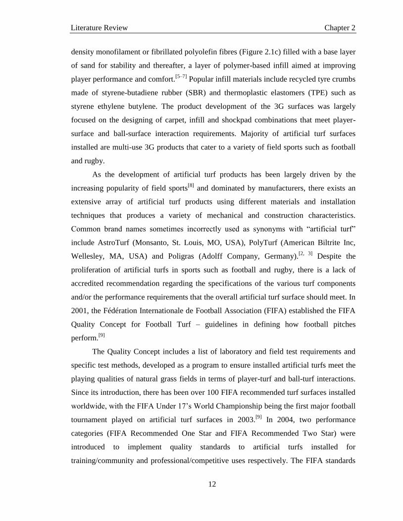
12
density monofilament or fibrillated polyolefin fibres (Figure 2.1c) filled with a base layer
of sand for stability and thereafter, a layer of polymer-based infill aimed at improving
player performance and comfort.[5–7]
Popular infill materials include recycled tyre crumbs
made of styrene-butadiene rubber (SBR) and thermoplastic elastomers (TPE) such as
styrene ethylene butylene. The product development of the 3G surfaces was largely
focused on the designing of carpet, infill and shockpad combinations that meet player-
surface and ball-surface interaction requirements. Majority of artificial turf surfaces
installed are multi-use 3G products that cater to a variety of field sports such as football
and rugby.
As the development of artificial turf products has been largely driven by the
increasing popularity of field sports[8]
and dominated by manufacturers, there exists an
extensive array of artificial turf products using different materials and installation
techniques that produces a variety of mechanical and construction characteristics.
Common brand names sometimes incorrectly used as synonyms with “artificial turf”
include AstroTurf (Monsanto, St. Louis, MO, USA), PolyTurf (American Biltrite Inc,
Wellesley, MA, USA) and Poligras (Adolff Company, Germany).[2, 3]
Despite the
proliferation of artificial turfs in sports such as football and rugby, there is a lack of
accredited recommendation regarding the specifications of the various turf components
and/or the performance requirements that the overall artificial turf surface should meet. In
2001, the Fédération Internationale de Football Association (FIFA) established the FIFA
Quality Concept for Football Turf – guidelines in defining how football pitches
perform.[9]
The Quality Concept includes a list of laboratory and field test requirements and
specific test methods, developed as a program to ensure installed artificial turfs meet the
playing qualities of natural grass fields in terms of player-turf and ball-turf interactions.
Since its introduction, there has been over 100 FIFA recommended turf surfaces installed
worldwide, with the FIFA Under 17’s World Championship being the first major football
tournament played on artificial turf surfaces in 2003.[9]
In 2004, two performance
categories (FIFA Recommended One Star and FIFA Recommended Two Star) were
introduced to implement quality standards to artificial turfs installed for
training/community and professional/competitive uses respectively. The FIFA standards

Literature Review Chapter 2
13
have since been adopted by other sport governing bodies; with the Union of European
Football Associations (UEFA) allowing the play of the UEFA Champion League and
UEFA Cup competitions on FIFA Two Star turfs beginning 2005[9]
and the International
Rugby Board (IRB) introducing the Regulation 22 detailing performance specifications
for artificial turfs used for rugby.[10]
2.2.2 Epidemiological Studies
With the rapidly increasing popularity of field sports, the introduction of 3G
artificial turfs as alternative playing surfaces cater to the high sport participation rates,
fuelling the rapid installation of such products. The effects of such large scale adoption of
artificial turfs were only realized in the late-2000s, when there was an influx in published
literature comparing the injury rates sustained on natural grass fields and 3G artificial turf
surfaces (Figure 2.2). Such studies have thus become a key tool in identifying underlying
problems of artificial turf surfaces, by relating injury patterns to surface properties and
aim to contribute a better understanding of player-surface interaction that may eventually
lead to increased safety and improved athlete performances.
Figure 2.2. Number of literature publications, from 1990 to date (2016), on artificial turf surfaces
and related epidemiological studies. “Artificial Turf” is abbreviated as “AT” in the figure. Data
retrieved from the Web of ScienceTM
Core Collection.[11]

Literature Review Chapter 2
14
In 2006, the consensus statement for epidemiological studies of injuries was
published by Fuller et al. under the FIFA Medical Assessment and Research Centre (F-
MARC), detailing the definitions, methodology and implementation of data collection.[12]
The consensus statement – on which most epidemiological studies are based – adopts a
“time-loss” definition for recordable injuries, where the incident is classified as an injury
when the player is unable to participate fully in matches or trainings the day following
the incident. The severity of sustained injuries are thus defined based on the time (in days)
required for the player to return to full participation in training and matches; with the day
on which the injury occurred being day zero. Despite the consensus statement, there
exists high subjectivity in the determination of the level of severity – with some studies
considering a time loss of approximately 1 – 6 days as mild, 7 – 28 days as moderate and >
28 days of absent as severe[13–17]
, while others included more sub-categories[18–20]
and/or
considered an injury resulting in more than 21 days of absent as severe.[21–25]
Injuries are
also classified by location on the body, type of injury, and as “acute” or “overuse”
depending on its onset rate and level of trauma associated. In most studies which
compare injury rates on different playing surfaces, overuse injuries are often omitted as
the cause of such injuries cannot be attributed to any single, identifiable event, e.g. the
surface on which the injury was sustained.
From the epidemiological studies reviewed, various conclusions have been drawn
regarding the effect of playing surface on the risk of injuries; though majority of studies
found no overall difference in the acute injury rates between natural grass and artificial
turf surfaces[13, 14, 16, 19–21, 25]
. The studies, however, highlighted the surface-dependency of
specific injury types; of which, findings varied between the studies as well. Steffen et al.
surveyed the injury risks of young female Norwegian footballers throughout the
competitive league season from March to October 2005.[21]
They observed that ankle
sprain was the most common type of injury sustained on both surfaces, with a trend
towards more ankle sprains occurring on artificial turf surfaces. Higher incidences of
ligament and knee injuries were also recorded on artificial turf surfaces, and were
attributed to higher shoe-surface traction.[21]
On the contrary, studies by Meyers et al. and
Ekstrand et al. found lower incidences of lower-limb strains on artificial turf surfaces,
with instead, an increased number of muscle and tendon injuries on the 3G playing

Literature Review Chapter 2
15
surfaces[18, 22]
and Aoki et al. observing higher incidences of lower back pain from
players training on artificial turfs.[15]
The non-conclusive observations from studies comparing natural grass and
artificial turf surfaces can be attributed to the extensive population base across which the
studies have been conducted – with factors such as sample size, age group, level of play,
gender, ethnicity and duration of study contributing to the varying statistical conclusions.
In addition, the highly varied surface properties and lack of knowledge in player
biomechanics on the playing surfaces creates great challenge for comprehensive and
conclusive studies.
Although there exist differing opinions on the injury risks of artificial turfs, the
surfaces have consistently been deemed abrasive. The highly abrasive nylon-based 1G
surfaces in the 1960s have since led to negative connotations associated artificial turfs[26–
28], with players relating such surfaces with higher risks of turf burns, despite the
introduction of softer polyolefin fibres for the 2G and 3G products.[29–31]
2.2.3 Skin Abrasion on Artificial Turf Surfaces
The time-loss definition commonly used in epidemiological studies meant that
skin-related injuries are largely omitted from the injury recording protocol as the severity
of such injuries often do not require absence from gameplay or training (i.e. zero time-
loss). Of the limited studies that published data inclusive of skin-related injuries on
artificial turfs, it was found that higher rates of skin abrasions were recorded on artificial
turfs (AT) as compared to natural grass (NG) fields. Meyers et al. in their 5-year study
comparing injury rates of 1900 high school football athletes on 3G turfs and natural grass
fields found that surface and epidermal injuries contributed to 5.8% of the total number
of injuries recorded on artificial turf surfaces while only 0.8% of the injuries recorded on
natural grass are due to abrasion.[22]
A similar trend was observed by Fuller et al. while
analysing results from 106 men teams over two American college and university football
seasons, where a higher incidences of laceration/skin lesion injuries were sustained by
male players during matches on artificial turfs (7.1% of all AT injuries) as compared to
games on natural grass (2.6% of all NG injuries).[13]
Ekstrand et al.’s 5-year study of elite
level Scandinavian male football players recorded higher rates of skin lesions sustained

Literature Review Chapter 2
16
from playing on artificial turf surfaces as well (3.6% of AT injuries vs 1.7% of NG
injuries).[19]
Although skin-related injuries such as abrasions, lesions and lacerations are seen to
have minimal effect on a player’s ability to perform, many field-users still prefer playing
on natural grass, citing the abrasiveness of artificial turfs as a major push factor.
Perception studies by Zanetti analysed inputs from 1671 male football players of the
Italian Amateurs League – players had to rate their opinions of artificial turf surfaces in
categories such as playing performances, ball-surface interactions and comfort.[29]
Overall results showed that artificial turfs were perceived to be better than natural grass
fields in all aspects of ball-surface and player-surface interactions with the exception of
the increased risk of abrasions. Elite football players were also concerned with the
abrasiveness of artificial turf surfaces, with over 60% of 1129 players across 43 countries
regarding artificial turfs as more abrasive than natural grass.[31]
Studies also showed that
there is a tendency for athletes to adapt their playing styles when playing on artificial turf
surfaces. In particular, Andersson et al. and Poulos et al. found that a lower number of
sliding tackles are performed on artificial turfs as compared to natural grass, attributed to
the higher perceived risks of turf burns.[32, 33]
In addition to damage to the skin, the increased incidences of skin abrasion also
raises the risk of infections by pathogens. The presence of abrasions or open wounds act
as points of entry for bacteria[34]
either through cross-contamination by infected
individuals or interaction with poorly-sanitized sports facilities such as playing surfaces,
gyms or changing rooms. A study into a bacteria outbreak in 2003, amongst a college
football team in Connecticut, USA was carried out to document the incident and provide
guidelines for related policies.[35]
Methicillin-resistant Staphylococcus aureus (MRSA)
was identified as the infection-causing pathogen and interviews revealed that majority of
infected players suffered from turf burns, with the risk of infection on a player with skin
abrasion injuries being 7 times that of players without abrasion injuries. In a separate
study by Kazakova et al., the increased frequency and severity of skin abrasions sustained
on artificial turf surfaces was also attributed to the MRSA outbreak among the
professional football team in Missouri, USA.[36]
The locations of the infections (elbow,

Literature Review Chapter 2
17
forearm, thigh and knee) also coincide with that of turf burns – areas on the body that are
often exposed.
Apart from the introduction of polyolefin fibres in 2G products, there has been
little progress in the development of the artificial turf systems to reduce skin abrasiveness.
Patented turf yarn technologies that promote skin-friendliness also largely attribute the
reduced abrasiveness to the use of polyolefins, without significant advances in
technology. Such “skin-friendly” products often lack supporting frictional assessments to
justify their claims.[37–40]
From the review of literature, the abrasiveness of artificial turf
playing surfaces still remains as an issue that has yet to be addressed and is a critical
factor affecting the acceptance of artificial turfs as an alternative to natural grass fields.
2.2.4 Quality Standards and Test Methods
The FIFA-08 test method is the widely used industry standard for determining the
friction and abrasive properties of artificial turf surfaces, part of the Quality Concept for
accrediting 3G artificial turf surfaces.[41]
It involves the use of the Securisport Sports
Surface Tester (Wassing Messtechnik GmbH, Germany) which runs a silicone skin-
attached test foot across a 1 m2 prepared artificial turf surface. The standard is currently
used by the governing bodies for football (soccer), Australian football, Gaelic football,
rugby union and rugby league.[42]
The following test protocol is adapted from the FIFA Quality Concept, Handbook
of Test Methods[43]
: Artificial turf surfaces of manufacturer’s specifications are prepared
in accordance to FIFA guidelines for lab-based testing. The L7350 silicone skin (Maag
Technic AG, Switzerland) are first sized, washed and dried prior to testing. The L7350
was selected as a skin model to simulate skin-turf interaction – hereafter referred to as
“skin”.
Prepared “skins” where then assessed for their manufacturing consistency via a
friction measurement over a standardized stainless steel plate; “skin” samples failing the
assessment were rejected while the sliding force value was recorded for qualified samples.
The “skin” samples are then attached to a steel test foot and secured to the Securisport,
which is placed on the artificial turf surface. The test foot is rotated for 5 turns across the
surface at a speed of 40 rpm, under a normal load of 100 N to produce a time profile of

Literature Review Chapter 2
18
the measured coefficient of friction (COF). The software calculates an average COF
value for the trial – which is used to represent the “skin-surface friction” in the test report.
Tested “skin” samples are measured again using the stainless steel plate, and the
difference between the sliding forces recorded before and after Securisport trials are
manipulated and determined as the “skin abrasion” value. To meet the FIFA
Recommended Two Star and One Star requirements, artificial turf surfaces must have a
skin-surface friction value of between 0.35 and 0.75 as well as a skin abrasion value of ±
30%. As per the other standards set out in the Quality Concept, there is no documented
justification on how these performance standards have been determined or correlate with
player/ball-turf interactions. There has also been no published literature on work done
with the Securisport in accordance to the FIFA-08 test.
Despite limited assessments of the industry standard, the Securisport has been
widely critiqued for its lack of biofidelity to player movement during a game setting.
Verhelst et al. questioned the rotational measurements at constant speed under a non-
representative normal load; and proposed a sliding tester comprising of an inclined track
and a “skin”-attached sledge which provides linear sliding motion and allows the
monitoring of temperature changes at the “skin”-turf interface during sliding.[44]
However,
their conclusion which related higher temperature rises with increased risk of abrasion
was not supported by their results where they determined a large extent of skin abrasion
on sand-filled 2G turfs which showed the lowest temperature rise.
Highlighting similar limitations of the Securisport, Ingham designed a study to
better understand the biomechanics behind sliding tackles.[45]
Subjects were asked to
perform sliding tackles on artificial turf surfaces and their motion analysed using video
cameras. Of the five participants, the average velocity prior to the manoeuvre was
determined to be 6.47 m/s and the sliding duration lasted less than 1 s. Although the
tested population is small and subjects were decked in excess protective clothing which
may affect the sliding motion; this study provides motivation for future work in the
determination of testing parameters that may improve the biofidelity of skin-friction
assessment methods.
The only available literature that reported studies involving the Securisport device
was conducted by Lenehan and Twomey.[46]
They compared the abrasiveness of three

Literature Review Chapter 2
19
different artificial turf surfaces (filled with 16 mm of sand, sand and rubber to the depth
of 30 mm and sand and rubber to the depth of 38 mm) using the Securisport device and a
modified mechanical tester. The modified tester was designed to simulate the linear
motion of the sliding tackle, moving a similar ‘skin’-attached test foot across a 4 m turf
sample at a speed of 5 m/s. As the modified tester did not measure ‘skin’-turf friction
values, the assessment of abrasiveness was solely carried out through the comparison of
the skin abrasion value, as computed in accordance to the FIFA-08 method. A trend of
increasing abrasion with infill depth was concluded, though the reported abrasion values
were high, with large standard deviations: overall mean abrasion values of 86.2% ± 38.49%
for the Securisport and 34.5% ± 91.33% for the modified tester (both exceeding the
acceptable FIFA compliance of 30%). It is difficult to assess the effectiveness of the
modified tester in better simulating skin-turf interaction as the large deviation may mask
the statistical significance of the reported data.
The American Society for Testing and Materials (ASTM) published a test
procedure in 2003, that measures the relative abrasiveness of artificial turf surfaces using
an Abrasive Index (AI) (ASTM ID: F1015).[47]
This standard is rarely referred to in
product specifications due to the irrelevance of the test. The AI is calculated based on the
decrease in mass of a friable foam block after abrasion on an artificial turf surface; yet the
recommended/acceptable AI values for products to be qualified as skin-friendly is
lacking. Furthermore, the rigid foam block is deemed as a poor human skin model, hence
is not representative of skin-turf interactions.
The use of a standard skin model or test counter-surface is essential in the
characterization of skin-friendliness in order for effective and reliable product
assessments. An example of misrepresentation of skin-friendly properties is demonstrated
in the specifications of commercial product Sport Court ® SportGameTM
. The multi-
purpose sport surface is marketed as “low abrasion for safe play”[48]
which denotes the
surface having low skin abrasion properties. However, the product (according to its
technical data sheet) was assessed using ASTM ID: C1028 – which measures the friction
of ceramic tile and like surfaces using a synthetic acrylic-based counter-surface.
There is therefore much room for research for the better understanding of human-
turf interactions in the areas of biomechanics, surface properties and behaviour, and

Literature Review Chapter 2
20
assessment standards. The current gaps in knowledge pose limitations to the goal of
addressing abrasiveness of turfs and hinder the aim of achieving skin-friendly artificial
turf surfaces.
2.3 Skin-Friendly Surfaces
Skin-friendly materials have been much sought after in various end applications
such as cosmetics, personal healthcare and textiles, each of which focusing on a different
aspect of material property. Skin-friendliness as applied in cosmetics and skin-care
involves mainly the hydration capability of products when applied onto the human skin,
as in the case of moisturizers and lotions; as well as other intended effects such as UV-
protection, anti-ageing and acne treatment through the addition of active ingredients.[49, 50]
Such topical products also entail the requirement to be non-toxic to prevent adverse
effects such as irritation and allergies.
On the other hand, skin-friendliness in healthcare products may pertain to the
development of suitable barrier materials and adhesives for wound-care – for breathable
protection that can be safely removed without additional trauma to the dermis.[51]
Whereas the definition of skin-friendliness in textile applications largely involves the
frictional interaction between skin and fabric with the objective of improving clothing
comfort.[52, 53]
In the context of artificial turf surfaces, we define skin-friendliness as reduced
skin-turf friction, coupled with anti-microbial properties to reduce the risk of turf burns
and subsequent bacterial infections originating from the synthetic playing surface.
2.3.1 Technologies in Polymer Surface Modification
The 3G artificial turf surface that is in direct contact with the human skin
comprises of solely polymeric materials – polyolefins turf fibres and styrene-butadiene
rubber infill. Product development and innovation by manufacturers has focused efforts
on optimizing the mechanical properties of the turf components, in particular, a wide
range of carpet products with improved tear resistance, durability and resiliency.[54–56]
It would therefore be ideal to integrate skin-friendliness into the designed carpet
products, without affecting mechanical properties of the bulk material so as to conserve
Literature Review Chapter 2
21
the optimized performances of the fibres. Polymers are a wide class of materials used for
an extensive range of applications, often exposed to various physical and chemical
conditions.[57–59]
Most synthetic polymers are hydrophobic in nature, with low surface
energy and hence poor adhesion to polar coatings and dyes. Their hydrophobic nature
also promotes the adsorption of proteins and cells, introducing biofouling issues in
applications such as water filtration, microfluidics and marine structures.[60]
In order to
impart superior properties to the material, much work has been attributed to the surface
functionalization of polymers; modifying surface properties with minimal effect on the
bulk properties of the substrate.[61]
Strategies can be generalized into physical and
chemical methods.[59]
Physical methods such as deposition and lamination usually result in non-
covalently bonded coatings that are susceptible to wear and removal over time. Abrasion
and sandblasting may be used to increase roughness, surface energy and hence adhesion
of the applied coatings; but result in surface damage that introduces micro-cracks[62]
,
compromising the mechanical properties of the substrate. On the other hand, surface
activation via atom bombardment, plasma treatment and laser treatments require high
operating costs and/or elaborated equipment and infrastructure.[63]
Bearing large potential in the surface modification of materials, polymer brushes
provide for the flexibility to impart specific surface functions through the designing of
appropriate polymer grafts. Extensive research in surface grafting has contributed greatly
to the creation of novel surfaces, offering solutions in fields such as biomedical[64, 65]
,
packaging[66]
and membrane[67]
technology.
Polymer brushes are polymer chains that are anchored by one end to a substrate
and extend out into the surrounding medium, analogous to brush bristles. Polymers of
various chemical structures, compositions and functionalities can be tethered to the
substrate surface via physisorption or chemical bonding (Figure 2.3).[68, 69]
Physisorption
works on the principle that strong attraction exists between one end of the polymer chain
and the substrate, while the rest of the polymer interacts weakly with the substrate or has
a preferential attraction to the surrounding medium. Polycationic copolymer
poly(ethylenimine)-graft-poly(ethylene glycol) (PEI-g-PEG) chains subjected to
protonation at a pH of 7.4 were attached to negatively charged substrates via Coulombic

Literature Review Chapter 2
22
interactions to introduce interfacial lubrication when equilibrated in good solvents.[70, 71]
Works on the physisorption of polyethylene oxide (PEO) brushes to prepare protein-
resistant surfaces[72, 73]
have also demonstrated the ease and effectiveness of the method
yet the stability and durability of such physisorbed brushes are highly dependent on the
surroundings – where a change in pH, ionic strength or mechanical agitation can dislodge
the brushes.[74]
The reversible nature of such adsorption renders the coating thermally and
solvolytically unstable.
Chemical bonding of polymer brushes onto the substrate thus provides for surface
modifications of improved robustness. Polymer brushes can be grown on substrates via
the “grafting-to” or “grafting-from” approaches. The “grafting-to” method involves the
attachment of prepared polymer chains with functional ends to the reactive sites present
on the substrate surface. This allows for the controlled, narrow molecular weight
distribution of attached polymer brushes, providing uniform surface properties. However,
due to the bulky sizes of the prepared polymer chains, the grafted coating forms a
diffusion barrier against subsequent polymer chains from accessing the substrate surface.
Hence, the “grafting-to” technique often results in low grafting density and incomplete
surface coverage, stemming from steric repulsion between polymer chains.[74]
Figure 2.3. Schematics of polymer brush preparation using physisorption, “grafting-to” and
“grafting-from” techniques.
The “grafting-from” approach starts with the immobilization of initiators or
functional groups on the substrate surface. The reactive species are then activated and
exposed to monomer units that polymerize from these reactive sites to form tethered
Literature Review Chapter 2
23
brushes. Grafting can take place in gas or liquid phases, with surface activation carried
out by means such as heat, ultraviolet (UV) irradiation or plasma dosing, followed by
propagation through free radical polymerization. UV-induced surface grafting has been
extensively applied for the modification of polymeric substrates, often involving the use
of benzophenone (BP) and its derivatives as photoinitiators due to their high grafting
efficiencies.[75]
In addition, advantages such as fast reaction rates, low equipment cost
and ease of scalability result in UV-induced grafting being a favourable surface
modification technique, which can be readily integrated into manufacturing lines.[66, 75]
The continuous grafting process developed by Yao et al. can be used for the surface
modification of extruded polymeric yarns by installing additional reactant tanks and a UV
lamp after the extruder. These modular add-ons allow for the surface grafting of large
volumes of polymeric substrate, which can subsequently be cut to length and tufted into a
carpet.
The random nature of free radical polymerization often results in uneven surface
grafting of varying brush lengths. The development of the atom transfer radical
polymerization (ATRP) process by Professor Matyjaszewski in 1994 allowed for the
preparation of surfaces with highly controllable graft lengths and properties.[76]
This
initiated extensive research into the designing and development of polymer grafts, with
endless possibilities for novel surfaces and applications.[74, 77–80]
The controlled process of
ATRP involves the suppressing of side reactions such as termination and radical transfer,
via the use of a transition metal complex for the reversible activation and deactivation of
the highly reactive radicals. This process is repeated with the continuous shift in
equilibrium between the “living” and “dormant” polymer chains, to result in the
propagation process. The number of polymer chains is determined by the amount of
initiators present in the system, and each growing chain is subjected to the same
propagation rate – producing polymers with low polydispersities.[76, 81]
The ATRP
process also allows for the designing of multi-block copolymers through the control of
reaction time and monomers used.
The popular method of ATRP does, however, bear the shortcomings of stringent
reaction conditions and comparably, longer reaction times involved. The transition metal
catalysts used in the process will also manifest in the products for which expensive

Literature Review Chapter 2
24
separation techniques will have to be used to render the produced polymers as
commercially useful.
2.3.2 Polymer Brushes for Reduced-Friction Properties
Polymer brushes have been extensively studied for their lubricating properties and
may have great potential in the reduction of skin-turf friction that causes abrasion injuries.
The solvation of tethered brushes results in the swelling of the brushes that forms a
lubricating barrier that reduces high-frictional interaction between the substrate and
counter-surface. Nomura et al. investigated the lubrication mechanism of grafted
polystyrene (PS) brushes in varying solvent compositions and found that in the presence
of good solvent (toluene), the fully extended PS brushes were capable of reducing the
coefficient of friction (µ) to orders of 10-4
whereas that measured in non-solvent (2-
propanol)-rich mixtures were in the order of 10-1
.[82]
In exploring surfaces with controllable frictional properties, Vyas et al. designed
binary polystyrene-poly(2-vinylpyridine) (PS-P2VP) brushes that successfully switched
between high and low friction when treated with different solvents (toluene and
ethanol).[83]
When exposed to ethanol, the hydrophilic P2VP brushes extended into the
solvent medium due to favourable hydrogen-bonding. Frictional measurements using a
hydrophilic poly(acrylic acid) (PAA) colloidal probe resulted in µ values more than 50%
higher than that of toluene-treated samples (extended PS brushes) due to the attractive
adhesive forces between the like P2VP-PAA interface as compared to repulsive forces
between the dissimilar PS-PAA interface.
Identifying that water may be a preferred lubricant in aqueous-rich environments
surrounding applications such as textiles, pharmaceutical and biomedical products[84]
,
Minn et al., studied the frictional properties of spin-casted and surface-grafted
poly(methyl methacrylate) PMMA in submerged aqueous environments. They concluded
that PMMA brushes that were covalently bonded to the substrate surface exhibited lower
frictional values and were more wear-resistant as compared to the spin-casted films when
tested with a stainless steel ball.
The abundance of water molecules in many applications makes it easily available
as a lubricating agent as compared to traditional oil-based lubricants. Research on

Literature Review Chapter 2
25
hydration lubrication by polymer brushes has been enhanced by the development of
biomaterials for applications such as joint implants. Moro et al.[65]
studied the effects of
photoinduced grafting of poly(2-methacryloyloxyethyl phosphorylcholine) (pMPC)
brushes to rigid cross-linked polyethylene substrates in reducing the effect of
periprosthetic osteolysis – the loss of bone surrounding prosthesis implants due to
excessive wear. The solvated biocompatible pMPC brushes provided excellent
lubrication of the joint implant, with µ values lowered from 0.8 to 0.1 and a reduction of
wear up to forty times that of unmodified substrates.
While hydrophilic polymers perform well in hydration lubrication, polyzwitterions
have been found to provide extreme lubrication in the presence of water. The electrostatic
attractive forces between the charged functional groups and water molecules result in a
strongly-bounded hydrated layer that is robust to repeated testing and provides enhanced
lubrication. Several studies have confirmed the effectiveness of hydrated surface-grafted
polyzwitterions in reducing interfacial friction and demonstrated the functionalities of
these polymer brushes even under high pressure conditions.[85–89]
However, from the review of published literature, there seems to be limited work
on the application of polymer brushes for lubrication under ambient conditions, outside
of the aqueous environment – such as in the case of an artificial turf surface. In addition,
no work has been carried out to study the frictional properties of surface-grafted polymer
brushes using skin models that simulate interaction with the human skin – the key scope
of this thesis. The published work presented in this section have also assessed the
effectiveness of the prepared samples using different tribological methods, counter
surfaces, loadings and conditions; factors have great influences on the absolute
coefficient of friction reported. Research into the area of reduced skin-friction using
polymer brush-grafted surfaces is therefore beneficial, enhanced by the development of a
testing protocol that allows for the comparison of the skin-friendliness of modified
surfaces.
2.3.3 Polymer Brushes with Antifouling Properties
Biological fouling has been an ongoing issue faced by many industries, with
possibly the greatest impact in marine operations. The undesirable growth of marine

Literature Review Chapter 2
26
organisms on immersed artificial structures result in large economical losses
consequential of increased fuel consumption, reduced operational efficiency and cost
incurred in maintenance and repair[90]
; as well as accelerating corrosion and increasing
risk of mechanical failure of piers and jetties.[91]
The development of antifouling solutions has evolved over the last 2000 years[92]
stemming from the physical surface modification of painting of ship hulls with biocidal
metallic paints. Antifoulants such as cuprous oxide and organitin compounds were
subsequently introduced into antifouling paints, complemented by delivery systems that
allowed controlled releasing of the biocides to prolong the antifouling effects. The release
of these toxins, however, had detrimental impacts on the environment, upsetting the
marine food chain and were eventually banned in 2008.[60, 93]
Environmentally-friendly
polymer solutions were thus developed along two general strategies: fouling-release and
antifouling.[60]
Fouling-release surfaces such as polydimethylsiloxane (PDMS) and fluoroalkyl
brushes, are hydrophobic and low in surface energy – allowing for the easy removal of
bioorganisms by the hydrodynamic shear forces experienced when a vessel moves
through the water.[94]
On the other hand, antifouling surfaces (hydrophilic in nature) are
resistant to protein and cell adhesion, preventing the settling of bioorganisms onto the
surface.[95, 96]
The mechanism for biofouling has yet to be fully understood, though many
studies have discussed the role of surface bound water in the inhibition of protein
adsorption. Hydrophilic macromolecules when in contact with water, restrain the
movement of water molecules through hydrogen-bonding – forming a hydrated layer.
Ishihara et al. explained the adsorption of proteins through the displacement of
water molecules from the fouled surface.[97]
For a hydrophobic substrate, water molecules
interact with the surface via weak van der Waals forces that are easily broken when a
protein molecule approaches and adsorbs onto the surface. The protein molecule then
undergoes irreversible conformation changes, promoting hydrophobic attraction to the
surface. Whereas a network structure of water molecules forms on the surface of
antifouling hydrophilic substrates, through extensive hydrogen bonding. Approaching
proteins need to overcome a large energy barrier in displacing the strongly bounded water
molecules so as to access the surface.[69, 98]

Literature Review Chapter 2
27
Poly(ethylene glycol) (PEG) and its copolymers have been well established as
having antifouling properties, reducing protein adsorption onto PEG-coated surfaces.[69, 99,
100] Jeon et al. attributed the antifouling property of PEG-tethered surfaces to the elastic
and osmotic stress deriving from compression of the PEG chains as modeled proteins
approach the surface – resulting in steric repulsion of the incoming protein molecules.[101]
The tendency for PEG to auto-oxidize[102]
and degrade in the presence of oxygen affects
the durability of its antifouling properties. Hence extensive research has been carried out
in the designing of alternative polymer systems with antifouling properties, based on
characteristics of hydrophilicity, ability to form hydrogen bonds with water and
conformational flexibility.[103]
More recently, zwitterionic polymers have received increasing attention as
antifouling surfaces – with common species such as carboxybetaine, sulfobetaine and
phosphorylcholine (Figure 2.4). These electrically neutral, charge-bearing entities interact
strongly with water molecules via electrostatic attraction[104]
and the strong binding to
water of zwitterionic polymers results in a greater extent of protein resistance as
compared to typical hydrophilic counterparts.[103]
Such antifouling zwitterionic surfaces
have been highly sought after in the biomedical industry, for applications such as
implants and biosensors; where protein adhesion may cause infection, clogging and
device faults. This has led to the development of coatings that are both antifouling and
biocompatible. It was from the bio-inspiration of red blood cells, that phospholipids were
studied as antifouling surface coatings as blood cells suspended in a protein environment
of blood plasma exhibited resistance towards fouling by protein adsorption.[105]
Zwitterionic phosphorylcholine found in the “head” of the phospholipid cell walls was
attributed for this antifouling property.
Figure 2.4. Chemical structures of common species of zwittertions, entities that bear both
positive and negative charges but are electrically neutral.

Literature Review Chapter 2
28
Figure 2.5. Schematic describing the continuous exchange of free water molecules adsorbed by
tethered zwitterionic polymer brushes, with the bulk water molecules surrounding fouling bodies
such as proteins and bacteria cells.
Analysis of the adsorbed water layer on zwitterionic polymer brushes was found to
consist largely of free water molecules[97, 106, 107]
, interacting with a tightly-bounded layer
of nonfreezable water adjacent to the zwiterionic entities. The free water molecules
display similar behavior to those present in the bulk water surrounding proteins and
microorganisms and hence allow for the continuous exchange of water molecules
between the fouling body and the zwitterionic surface (Figure 2.5), without stimulating
conformation changes preceding fouling behaviour. The biomimetic nature of zwitterions
render them both antifouling and biocompatible properties, hence popularly used in
biomedical applications for the surface treatment of implants such as scaffolds and
joints.[108, 109]
2.4 Evaluation of Literature Review
This review of literature has covered the two main sections regarding the issue of
skin abrasion injuries on artificial turf surfaces, and strategies of improving skin-
friendliness of a surface via material modification. The review has highlighted the need
for further research, focusing on the general lack of scientific knowledge and evidence
regarding skin-turf friction and work straddling the two presented sections has yet to be
carried out.

Literature Review Chapter 2
29
The issue of skin abrasion on artificial turfs is widely known but lacking in
published reports due to the protocols for injury recording leading to the common
omission of skin-related injuries. Of the limited published studies, the risk of skin
abrasion injuries is still of great concern to users of the current day 3G products – with
higher skin-related injury rates recorded on artificial turf fields and players consistently
perceiving such playing surfaces as abrasive.
Having established skin abrasions as an ongoing challenge facing the acceptance
of artificial turf surfaces, it is important to create an understanding of the skin-turf
interaction. Despite the large number of FIFA and Rugby accredited 3G artificial turf
surfaces worldwide, there is little published research on the frictional behaviour of
artificial turf or on the standard mechanical testing currently used to determine skin-
surface friction for 3G turfs.
The current industry standard used for assessing skin-abrasiveness of artificial
turfs has received much criticism due to its non-biofidelity yet the lack of literature
describing the biomechanics of the sliding motion by players during a football or rugby
game poses as a limitation to the development of better testing devices. Testing and
assessment using mechanical test devices however, are preferred as they provide high
levels of repeatability and allows for the isolation of individual test variables for
evaluation. Better utilization of the available test device and rigorous data analysis can
hence provide insights to explaining skin-turf interaction, with better understanding of the
friction-contribution of each turf component and allows for targeted product innovation
for the improvement of the overall skin-friendliness of the surface.
With the capability of identifying key turf components contributing to the overall
friction of the artificial turf system, strategies to improve the skin-friendliness properties
can be employed – with the aim of providing solutions to the ongoing issue of abrasive
turfs. The skin-friendly property relevant to the artificial turf industry has been defined as
providing reduced skin-surface friction as well as antifouling properties. Drawing
inspiration from the biomedical industry, surface-grafted zwitterionic brushes have
shown great potential in integrating the desired properties onto the artificial turf surface.
However, works presenting the excellent lubricating effects of such polymer brushes
have been conducted in well-solvated conditions where excess water molecules are

Literature Review Chapter 2
30
available for enhancing the lubricating effect. For applications such as in the case of
artificial turf surfaces, the skin-turf contacts are exposed to ambient conditions with the
presence of occasional but limited hydration. Application-specific configurations also
require the frictional properties of the grafted surfaces to be assessed with skin or skin-
like models that simulate interactions with the human skin – studies that are lacking.
Further research into mechanical assessments of skin abrasiveness of artificial turfs
together with work on materials modification for improved skin-friendliness will
contribute greatly to the advancement of knowledge and technology in achieving skin-
friendly artificial turf surfaces.
2.5 References
[1] B.M. Nigg and M.R. Yeadon, Biomechanical aspects of playing surfaces. J.
Sports Sci. 1987, 5, 117–145.
[2] I.M. Levy, M.L. Skovron, and J. Agel, Living with artificial grass: a knowledge
update. Part 1: Basic science. Am. J. Sports Med. 1990, 18, 406–412.
[3] P. Fleming and S. Forrester, Artificial turf—Surface properties and player–
surface interaction. J. Sci. Med. Sport 2013, 16, e17–e18.
[4] J.M. Wright and D. Webner, Playing field issues in sports medicine. Curr. Sports
Med. Rep. 2010, 9, 129–133.
[5] P. Fleming, Artificial turf systems for sport surfaces: current knowledge and
research needs. Proc. Inst. Mech. Eng. Part P J. Sport. Eng. Techonology 2011, 225, 43–
62.
[6] B.D. Patel and P.R.N. Desai, Thermoplastic Elastomer Infill Synthetic Turf. Int. J.
Innov. Reserach Sci. Eng. Technol. 2013, 2, 1182–1187.
[7] C. Walker, Performance of sports surfaces, in: Jenkins, M. (Ed.), Materials in
Sports Equipment Volume 1, Elsevier, 2003, p. 424.
[8] J. Dvorak, A. Junge, T. Graf-Baumann, and L. Peterson, Football is the most
popular sport in the world. Am. J. Sports Med. 2004, 32, 3S–4S.
[9] Fédération Internationale de Football Association (FIFA), FIFA Quality Concept
Requirements Manual, 2012.
[10] International Rugby Board (IRB), IRB Artificial Rugby Turf Performance

Literature Review Chapter 2
31
Specification. 2012.
[11] Thomson Reuters, Web of Science(TM) Core Collection. 2016.
[12] C.W. Fuller, J. Ekstrand, A. Junge, T.E. Andersen, R. Bahr, J. Dvorak, M.
Hägglund, P. McCrory, and W.H. Meeuwisse, Consensus statement on injury definitions
and data collection procedures in studies of football (soccer) injuries. Br. J. Sports Med.
2006, 40, 193–201.
[13] C.W. Fuller, R.W. Dick, J. Corlette, and R. Schmalz, Comparison of the
incidence, nature and cause of injuries sustained on grass and new generation artificial
turf by male and female football players. Part 1: match injuries. Br. J. Sports Med. 2007,
41 Suppl 1, i20–6.
[14] C.W. Fuller, R.W. Dick, J. Corlette, and R. Schmalz, Comparison of the
incidence, nature and cause of injuries sustained on grass and new generation artificial
turf by male and female football players. Part 2: training injuries. Br. J. Sports Med. 2007,
41 Suppl 1, i27–32.
[15] H. Aoki, T. Kohno, H. Fujiya, H. Kato, K. Yatabe, T. Morikawa, and J. Seki,
Incidence of injury among adolescent soccer players: a comparative study of artificial and
natural grass turfs. Clin. J. Sport Med. 2010, 20, 1–7.
[16] K. Kristenson, J. Bjørneboe, M. Waldén, T.E. Andersen, J. Ekstrand, and M.
Hägglund, The Nordic Football Injury Audit: higher injury rates for professional football
clubs with third-generation artificial turf at their home venue. Br. J. Sports Med. 2013, 47,
775–781.
[17] T. Soligard, R. Bahr, and T.E. Andersen, Injury risk on artificial turf and grass in
youth tournament football. Scand. J. Med. Sci. Sport. 2012, 22, 356–361.
[18] J. Ekstrand, T. Timpka, and M. Hägglund, Risk of injury in elite football played
on artificial turf versus natural grass: A prospective two-cohort study. Br. J. Sports Med.
2006, 40, 975–980.
[19] J. Ekstrand, M. Hägglund, and C.W. Fuller, Comparison of injuries sustained on
artificial turf and grass by male and female elite football players. Scand. J. Med. Sci.
Sport. 2011, 21, 824–832.
[20] M. Almutawa, M. Scott, K.P. George, and B. Drust, The incidence and nature of
injuries sustained on grass and 3rd generation artificial turf: a pilot study in elite Saudi

Literature Review Chapter 2
32
National Team footballers. Phys. Ther. Sport 2014, 15, 47–52.
[21] K. Steffen, T.E. Andersen, and R. Bahr, Risk of injury on artificial turf and
natural grass in young female football players. Br. J. Sports Med. 2007, 41 Suppl 1, i33–
37.
[22] M.C. Meyers and B.S. Barnhill, Incidence, causes, and severity of high school
football injuries on FieldTurf versus natural grass: a 5-year prospective study. Am. J.
Sports Med. 2004, 32, 1626–1638.
[23] M.C. Meyers, Incidence, mechanisms, and severity of game-related college
football injuries on FieldTurf versus natural grass: a 3-year prospective study. Am. J.
Sports Med. 2010, 38, 687–697.
[24] M.C. Meyers, Incidence, mechanisms, and severity of match-related collegiate
women’s soccer injuries on FieldTurf and natural grass surfaces: a 5-year prospective
study. Am. J. Sports Med. 2013, 41, 2409–20.
[25] J. Bjørneboe, R. Bahr, and T.E. Andersen, Risk of injury on third-generation
artificial turf in Norwegian professional football. Br. J. Sports Med. 2010, 44, 794–798.
[26] N. Levine, Dermatologic aspects of sports medicine. J. Am. Acad. Dermatol. 1980,
3, 415–424.
[27] W.F. Bergfeld and J.S. Taylor, Trauma, sports, and the skin. Am. J. Ind. Med.
1985, 8, 403–413.
[28] R.S.W. Basler, C.M. Hunzeker, and M.A. Garcia, Athletic Skin Injuries:
Combating Pressure and Friction. Phys. Sportsmed. 2004, 32, 33–40.
[29] E.M. Zanetti, Amateur football game on artificial turf: players’ perceptions. Appl.
Ergon. 2009, 40, 485–490.
[30] P. Burillo, L. Gallardo, J.L. Felipe, and A.M. Gallardo, Artificial turf surfaces:
Perception of safety, sporting feature, satisfaction and preference of football users. Eur. J.
Sport Sci. 2014, 14, S437–S447.
[31] J. Roberts, P. Osei-Owusu, A. Harland, A. Owen, and A. Smith, Elite Football
Players’ Perceptions of Football Turf and Natural Grass Surface Properties. Procedia Eng.
2014, 72, 907–912.
[32] H. Andersson, B. Ekblom, and P. Krustrup, Elite football on artificial turf versus
natural grass: movement patterns, technical standards, and player impressions. J. Sports

Literature Review Chapter 2
33
Sci. 2008, 26, 113–122.
[33] C. Poulos, J. Gallucci, W. Gage, J. Baker, S. Buitrago, and A. Macpherson, The
perceptions of professional soccer players on the risk of injury from competition and
training on natural grass and 3rd generation artificial turf. BMC Sports Sci. Med. Rehabil.
2014, 6, 11.
[34] M. Pecci, D. Comeau, and V. Chawla, Skin conditions in the athlete. Am. J.
Sports Med. 2009, 37, 406–418.
[35] E.M. Begier, K. Frenette, N.L. Barrett, P. Mshar, S. Petit, D.J. Boxrud, K.
Watkins-Colwell, S. Wheeler, E.A. Cebelinski, A. Glennen, D. Nguyen, and J.L. Hadler,
A high-morbidity outbreak of Methicillin-Resistant Staphylococcus aureus among
players on a college football team, facilitated by cosmetic body shaving and turf burns.
Clin. Infect. Dis. 2004, 39, 1446–1453.
[36] S. V Kazakova, J.C. Hageman, M. Matava, A. Srinivasan, L. Phelan, B. Garfinkel,
T. Boo, S. McAllister, J. Anderson, B. Jensen, D. Dodson, D. Lonsway, L.K. McDougal,
M. Arduino, V.J. Fraser, G. Killgore, F.C. Tenover, S. Cody, and D.B. Jernigan, A clone
of Methicillin-resistant Staphylococcus aureus among professional football players. N.
Engl. J. Med. 2005, 352, 468–475.
[37] E. Buriani and F. Zenoni, Thermoplastic synthetic fiber for producing artificial
grass mats or the like, process for the production thereof and mats incorporating said fiber,
WO 2008098905 A2, 2008.
[38] W. Olde, G.B. Slootweg, D. Van, L. Welzen, and C. Widdershoven, Artificial
fibre as well as an artificial lawn for sports fields provided with such fibre, EP1378592
A1, 2004.
[39] R. Luijkx, Artificial grass, US20130273268 A1, 2013.
[40] F. Atsma and D. Wildschut, Yarn for an artificial turf ground cover, artificial turf
ground cover and playing field including such a yarn and method for producing such a
yarn, US 7611763 B2, 2009.
[41] Fédération Internationale de Football Association (FIFA), FIFA Quality Concept
for football Turf: Handbook of Requirements, 2012.
[42] D.M. Twomey, L.A. Petrass, and P.R. Fleming, Abrasion injuries on artificial turf:
A real risk or not? South African J. Sport. Med. 2014, 26, 91–92.

Literature Review Chapter 2
34
[43] Fédération Internationale de Football Association (FIFA), FIFA Quality Concept
for Football Turf - Handbook of Test Methods, 2012.
[44] R. Verhelst, S. Rambour, P. Verleysen, and J. Degrieck, Temperature
development during sliding on different types of artificial turf for hockey, in:
International Conference on Latest Advances in High-Tech Textiles and Textile-Based
Materials, 2009, pp. 90–95.
[45] C. Ingham, Linear vs . Rotational Skin Friction, 2013.
[46] K.A. Lenehan and D.M. Twomey, Abrasion testing on synthetic turf: A modified
device. Proc. Inst. Mech. Eng. Part P J. Sport. Eng. Technol. 2015.
[47] ASTM International, ASTM Standard F 1015, 2003 (2009). Stand. Test Method
Relat. Abrasiveness Synth. Turf Play. Surfaces 2009.
[48] Sport Court, Sport Court ® SportGameTM Product Specifications, Salt Lake city,
Utah 2012.
[49] W.H. Schmitt, Skin-care products, in: Chemistry and Technology of the
Cosmetics and Toiletries Industry, Springer Netherlands, Dordrecht 1992, pp. 104–148.
[50] P.U. Giacomoni, Ageing, science and the cosmetics industry. EMBO Rep. 2005, 6,
S45–S48.
[51] P. Black, Peristomal skin care: an overview of available products. Br. J. Nurs.
2007, 16, 1048, 1050.
[52] E. Bertaux and M. Lewandowski, Relationship between Friction and Tactile
Properties for Woven and Knitted Fabrics. Text. Res. J. 2007, 77, 387–396.
[53] H. Strese, M. Kuck, R. Benken, J.W. Fluhr, S. Schanzer, H. Richter, M.C. Meinke,
J. Beuthan, C. Benderoth, G. Frankowski, W. Sterry, and J. Lademann, Influence of
finishing textile materials on the reduction of skin irritations. Ski. Res. Technol. 2013, 19,
409–416.
[54] P. Sandkuehler, E. Torres, and T. Allgeuer, Performance artificial turf
components — fibrillated tape, in: Procedia Engineering, Elsevier, 2010, pp. 3367–3372.
[55] P. Sandkuehler, E. Torres, and T. Allgeuer, Polyolefin materials and technology
in artificial turf I: Yarn developments. Sport. Technol. 2010, 3, 52–58.
[56] R. Hufenus, C. Affolter, M. Camenzind, and F.A. Reifler, Design and
characterization of a bicomponent melt-spun fiber optimized for artificial turf

Literature Review Chapter 2
35
applications. Macromol. Mater. Eng. 2013, 298, 653–663.
[57] J.E. Mark, Polymer Data Handbook, Oxford University Press, 1999.
[58] K. Kato, E. Uchida, E.T. Kang, Y. Uyama, and Y. Ikada, Polymer surface with
graft chains. Prog. Polym. Sci. 2003, 28, 209–259.
[59] A.S. Hoffman, Surface Modification of Polymers. Chinese J. Polym. Sci. 1995, 13,
195–203.
[60] J.A. Callow and M.E. Callow, Trends in the development of environmentally
friendly fouling-resistant marine coatings. Nat. Commun. 2011, 2, 1–10.
[61] J. Deng, L. Wang, L. Liu, and W. Yang, Developments and new applications of
UV-induced surface graft polymerizations. Prog. Polym. Sci. 2009, 156–193.
[62] L. Kumosa, D. Armentrout, and M. Kumosa, The effect of sandblasting on the
initiation of stress corrosion cracking in unidirectional E-glass/polymer composites used
in high voltage composite (non-ceramic) insulators. Compos. Sci. Technol. 2002, 62,
1999–2015.
[63] M.G. Moloney, Functionalized polymers by chemical surface modification. J.
Phys. D. Appl. Phys. 2008, 41, 174006.
[64] K. Ishihara, Bioinspired phospholipid polymer biomaterials for making high
performance artificial organs. Sci. Technol. Adv. Mater. 2000, 1, 131–138.
[65] T. Moro, Y. Takatori, K. Ishihara, T. Konno, Y. Takigawa, T. Matsushita, U.
Chung, K. Nakamura, and H. Kawaguchi, Surface grafting of artificial joints with a
biocompatible polymer for preventing periprosthetic osteolysis. Nat. Mater. 2004, 3,
829–836.
[66] B. Ranby, Surface modification and lamination of polymers by photografting. Int.
J. Adhes. Abrasives 1999, 19, 337–343.
[67] Y. Zhang, Z. Wang, W. Lin, H. Sun, L. Wu, and S. Chen, A facile method for
polyamide membrane modification by poly(sulfobetaine methacrylate) to improve
fouling resistance. J. Memb. Sci. 2013, 446, 164–170.
[68] H. Zeng, Polymer Adhesion, Friction, and Lubrication, John Wiley & Sons, 2013.
[69] S. Chen, L. Li, C. Zhao, and J. Zheng, Surface hydration: Principles and
applications toward low-fouling/nonfouling biomaterials. Polymer (Guildf). 2010, 51,
5283–5293.

Literature Review Chapter 2
36
[70] M.A. Brady, F.T. Limpoco, and S.S. Perry, Solvent-dependent friction force
response of poly(ethylenimine)- graftpoly(ethylene glycol) brushes investigated by
atomic force microscopy. Langmuir 2009, 25, 7443–7449.
[71] I.M. Nnebe, R.D. Tilton, and J.W. Schneider, Direct force measurement of the
stability of poly(ethylene glycol)-polyethylenimine graft films. J. Colloid Interface Sci.
2004, 276, 306–316.
[72] J.H. Lee, J. Kopecek, and J.D. Andrade, Protein-resistant surfaces prepared by
PEO-containing block copolymer surfactants. J. Biomed. Mater. Res. 1989, 23, 351–368.
[73] V.A. Liu, W.E. Jastromb, and S.N. Bhatia, Engineering protein and cell
adhesivity using PEO-terminated triblock polymers. J. Biomed. Mater. Res. 2002, 60,
126–134.
[74] B. Zhao and W.J. Brittain, Polymer brushes: surface-immobilized
macromolecules. Prog. Polym. Sci. 2000, 25, 677–710.
[75] Z.P. Yao and B. Ranby, Surface modification by continuous graft
copolymerization.* I. Photoinitiated graft copolymerization onto polyethylene tape film
surface. J. Appl. Polym. Sci. 1990, 40, 1647–1661.
[76] K. Matyjaszewski, Controlled Radical Polymerization. Control. Radic. Polym.
1998, 2–30.
[77] Y.C. Chiang, Y. Chang, A. Higuchi, W.Y. Chen, and R.C. Ruaan, Sulfobetaine-
grafted poly(vinylidene fluoride) ultrafiltration membranes exhibit excellent antifouling
property. J. Memb. Sci. 2009, 339, 151–159.
[78] H. Wang, T. Hirano, M. Seno, and T. Sato, Radical polymerization behavior of 3-
(N-2-methacryloyloxyethyl-N,N-dimethyl)ammonatopropanesulfonate in water. Eur.
Polym. J. 2003, 39, 2107–2114.
[79] T. Farhan, O. Azzaroni, and W.T.S. Huck, AFM study of cationically charged
polymer brushes: switching between soft and hard matter. Soft Matter 2005, 1, 66.
[80] M. Charnley, M. Textor, and C. Acikgoz, Designed polymer structures with
antifouling-antimicrobial properties. React. Funct. Polym. 2011, 71, 329–334.
[81] H. Bergenudd, Understanding the mechanisms behind atom transfer radical
polymerization : exploring the limit of control, KTH Royal Institute of Technology, 2011.
[82] A. Nomura, K. Okayasu, K. Ohno, T. Fukuda, and Y. Tsujii, Lubrication

Literature Review Chapter 2
37
Mechanism of Concentrated Polymer Brushes in Solvents: Effect of Solvent Quality and
Thereby Swelling State. Macromolecules 2011, 44, 5013–5019.
[83] M.K. Vyas, K. Schneider, B. Nandan, and M. Stamm, Switching of friction by
binary polymer brushes. Soft Matter 2008, 4, 1024–1032.
[84] M. Minn, M. Kobayashi, H. Jinnai, H. Watanabe, and A. Takahara, Effect of
Water Swelling on the Tribological Properties of PMMA Spin-Cast Film and Brush in
Aqueous Environment. Tribol. Lett. 2014, 55, 121–129.
[85] M. Chen, W.H. Briscoe, S.P. Armes, H. Cohen, and J. Klein, Polyzwitterionic
brushes: Extreme lubrication by design. Eur. Polym. J. 2011, 47, 511–523.
[86] M. Chen, W.H. Briscoe, S.P. Armes, and J. Klein, Lubrication at Physiological
Pressures by Polyzwitterionic Brushes. Science (80-. ). 2009, 323, 1698–1701.
[87] M. Kobayashi, M. Terada, and A. Takahara, Tribological Behavior of Polymer
Brushes Designed Based on Biomimetic Water Lubrication, in: Design for Innovative
Value Towards a Sustainable Society, Springer Netherlands, Dordrecht 2012, pp. 901–
904.
[88] K. Ikeuchi, Origin and future of hydration lubrication. Proc. Inst. Mech. Eng. Part
J J. Eng. Tribol. 2007, 221, 301–305.
[89] U. Raviv, S. Giasson, N. Kampf, J.-F. Gohy, R. Jérôme, and J. Klein, Lubrication
by charged polymers. Nature 2003, 425, 163–165.
[90] D.M. Yebra, S. Kiil, and K. Dam-Johansen, Antifouling technology - past, present
and future steps towards efficient and environmentally friendly antifouling coatings. Prog.
Org. Coatings 2004, 50, 75–104.
[91] Tropical Marine Science Institute (TMSI), Marine Biofouling and Antifouling.
2009.
[92] M.E. Callow, Ship fouling: problems and solutions. Chem. Ind. 1990, 5, 123–127.
[93] S. Krishnan, Marine Bioadhesion on Polymer Surfaces and Strategies for Its
Prevention, in: Polymer Adhesion, Friction, and Lubrication, 2013, pp. 227–281.
[94] C.J. Weinman, J.A. Finlay, D. Park, M.Y. Paik, S. Krishnan, H.S. Sundaram, M.
Dimitriou, K.E. Sohn, M.E. Callow, J.A. Callow, D.L. Handlin, C.L. Willis, E.J. Kramer,
and C.K. Ober, ABC triblock surface active block copolymer with grafted ethoxylated
fluoroalkyl amphiphilic side chains for marine antifouling/fouling-release applications.

Literature Review Chapter 2
38
Langmuir 2009, 25, 11274–12266.
[95] K.L. Prime and G.M. Whitesides, Adsorption of proteins onto surfaces containing
end-attached oligo(ethylene oxide): A model system using self-assembled monolayers. J.
Am. Chem. Soc. 1993, 115, 10421–10714.
[96] H. Ma, J. Hyun, P. Stiller, and A. Chilkoti, “Non-fouling” oligo(ethylene glycol)-
functionalized polymer brushes synthesized by surface-initiated atom transfer radical
polymerization. Adv. Mater. 2004, 16, 338–341.
[97] K. Ishihara, H. Nomura, T. Mihara, K. Kurita, Y. Iwasaki, and N. Nakabayashi,
Why do phospholipid polymers reduce protein adsorption? J. Biomed. Mater. Res. 1998,
39, 323–330.
[98] S. Chen, F. Yu, Q. Yu, Y. He, and S. Jiang, Strong resistance of a thin crystalline
layer of balanced charged groups to protein adsorption. Langmuir 2006, 22, 8186–8191.
[99] X. Ding, C. Yang, T.P. Lim, L.Y. Hsu, A.C. Engler, J.L. Hedrick, and Y.-Y.
Yang, Antibacterial and antifouling catheter coatings using surface grafted PEG-b-
cationic polycarbonate diblock copolymers. Biomaterials 2012, 33, 6593–6603.
[100] K. Ishihara, Y. Iwasaki, S. Ebihara, Y. Shindo, and N. Nakabayashi,
Photoinduced graft polymerization of 2-methacryloyloxyethyl phosphorylcholine on
polyethylene membrane surface for obtaining blood cell adhesion resistance. Colloids
Surfaces B Biointerfaces 2000, 18, 325–335.
[101] S.I. Jeon, J.H. Lee, J.D. Andrade, and P.G. De Gennes, Protein-surface
interactions in the presence of polyethylene oxide. J. Colloid Interface Sci. 1991, 142,
149–158.
[102] A. Hucknall, S. Rangarajan, and A. Chilkoti, In pursuit of zero: Polymer brushes
that resist the adsorption of proteins. Adv. Mater. 2009, 21, 2441–2446.
[103] I. Banerjee, R.C. Pangule, and R.S. Kane, Antifouling coatings: Recent
developments in the design of surfaces that prevent fouling by proteins, bacteria, and
marine organisms. Adv. Mater. 2011, 23, 690–718.
[104] Y. He, J. Hower, S. Chen, M.T. Bernards, Y. Chang, and S. Jiang, Molecular
simulation studies of protein interactions with zwitterionic phosphorylcholine self-
assembled monolayers in the presence of water. Langmuir 2008, 24, 10358–10364.
[105] B.G. Reuben, O. Perl, and N.L. Morgan, Phospholipid coatings for the prevention

Literature Review Chapter 2
39
of membrane fouling. J. Chem. Technol. Biotechnol. 1995, 63, 85–91.
[106] Y.-H. Zhao, K.-H. Wee, and R. Bai, Highly hydrophilic and low-protein-fouling
polypropylene membrane prepared by surface modification with sulfobetaine-based
zwitterionic polymer through a combined surface polymerization method. J. Memb. Sci.
2010, 362, 326–333.
[107] H. Kitano, T. Mori, Y. Takeuchi, S. Tada, M. Gemmei-Ide, Y. Yokoyama, and M.
Tanaka, Structure of water incorporated in sulfobetaine polymer films as studied by
ATR-FTIR. Macromol. Biosci. 2005, 5, 314–321.
[108] T. Cai, W.J. Yang, K.G. Neoh, and E.T. Kang, Poly(vinylidene fluoride)
membranes with hyperbranched antifouling and antibacterial polymer brushes. Ind. Eng.
Chem. Res. 2012, 51, 15962–15973.
[109] M. Kyomoto, T. Moro, T. Konno, H. Takadama, H. Kawaguchi, Y. Takatori, K.
Nakamura, N. Yamawake, and K. Ishihara, Effects of photo-induced graft polymerization
of 2-methacryloyloxyethyl phosphorylcholine on physical properties of cross-linked
polyehtylene in artificial hip joints. J. Mater. Sci. Mater. Med. 2007, 18, 1809–1815.

Literature Review Chapter 2
40

Experimental Methodology Chapter 3
41
Chapter 3
Experimental Methodology
This chapter presents the rationale behind the research work carried
out, with discussion on the principles underlying the experimental approach
used and justification on how the selected approaches are aimed at fulfilling
the objectives set out for the thesis. The work is divided into macro-scale
and micro-scale studies surrounding the overall theme of understanding and
reducing the skin abrasiveness of artificial turf surfaces.

Experimental Methodology Chapter 3
42
3.1 Introduction
From the presented review of studies pertaining to skin-abrasiveness of artificial
turf surfaces, it was shown that turf abrasion is still an issue of concern for current-day
products. The lack of understanding of turf abrasions stems from the limited studies on
player-turf interaction pertaining to skin, where it is still unclear what biomechanical
movements are involved in skin-turf contact and how the various turf components
contribute to the abrasion mechanism. The performance requirements and methodologies
used in available skin-turf friction standards are also not well justified. These gaps in
knowledge repress advancements in product development, where there is a lack of
product improvement to alleviate the problem of abrasive turfs.
The aims of this research project were to therefore a) develop a better
understanding of the effect of various turf components on the overall skin-turf friction
hence identifying the major friction-contributor and accordingly b) address the skin-
friendliness of the turf component through material modification. In order to achieve
these aims, a four-part experimental approach was proposed to
i) Investigate the contribution of the turf carpet, sand infill and rubber infill to the
overall friction of an artificial turf system;
ii) Investigate how to alter the surface properties of the previously identified turf
component;
iii) Study the effect of surface modification on the reduced friction and antifouling
properties – attributes of a skin-friendly surface and
iv) Critically evaluate the various skin-friction measurement methods.
The following chapter details the materials, methodologies and test equipment
used in this project. The experimental work is divided into macro-scale and micro-scale.
Macro-scale studies involve experiments on artificial turf systems built in the laboratory
in accordance to the skin-friction test guidelines from FIFA. The micro-scale studies
pertain to the chemical modification of surface properties of the identified polymeric
substrate, where frictional tests were conducted using a bench-top microtribometer.

Experimental Methodology Chapter 3
43
3.2 Research Methodology
To achieve the objectives set out in Chapter One of this thesis, a literature review
was first carried out to understand the physical characteristics of a third generation
artificial turf surface. The current issues concerning artificial turf surfaces were also
identified, together with the knowledge gaps and limitations hindering comprehensive
research and product advancements.
The individual components constituting a complete 3G surface are not regulated
by the quality standards published by sport governing bodies[1, 2]
and hence, there exists
large variations in product specifications in the market. The complexity multiplies when
installers mix and match turf components (e.g. shock-pads, sand and rubber infill and
carpets) from various manufacturers, resulting in thousands of permutations of turf
surfaces, each with its unique set of performance specification. This poses a fundamental
problem to the consumer, where a lack of consolidated product knowledge complicates
the selection process and prevents the making of an informed purchase.
It has been identified in Chapter Two that a persisting challenge for artificial turf
surfaces is the issue of abrasiveness to skin – with incidences reportedly higher than that
suffered on natural grass[3–5]
and negative perceptions[6–8]
deterring player acceptance of
the product. Yet, in efforts to produce 3G turfs that better simulate the characteristics of
natural grass fields, the cause of higher skin abrasion incidences on artificial turf surfaces
is still unstudied. It is therefore necessary to conduct controlled studies on skin-surface
friction to understand the influence of individual turf components on the overall friction
of the system. A range of materials used in the construction of 3G surfaces was selected,
representative of typical variables existing across products.
A mechanical test method was selected for the evaluation of skin-surface friction
as it allows for repeatable results and standardized comparison of frictional behaviour
across the various constructed 3G surfaces, as compared to subject-based testing. The
selected FIFA-08[9]
test method involves the use of a silicone skin-replica for simulation
of skin-surface interactions and is preferred over in vivo testing on live subjects due to the
inconsistency of human skin properties[10–14]
and ethical considerations. The standard test
method FIFA-08 which uses the Securisport Surface Tester was chosen over newer
innovative turf friction devices as there is insufficient literature to validate the capabilities

Experimental Methodology Chapter 3
44
of the latter systems. As highlighted in Chapter Two, the lack of understanding of the
biomechanics of player sliding motion on turf poses a limitation to the designing of better
testing devices. Hence, albeit shortcomings, the Securisport Surface Tester was deemed
capable of distinguishing between various 3G turf systems and identifying key frictional
characteristics of each surface.
From the above study, the turf component with dominant influence on the overall
surface friction was determined from analysis of the frictional profiles of the constructed
3G surfaces. The strategy of surface modification was then applied to impart skin-
friendly properties onto the identified turf component, with minimal effect on bulk
mechanical properties. The identified substrate was subjected to photo-induced grafting
of polymer brushes – a scalable method that can be easily integrated into the production
process which also provides the flexibility to tune surface properties via the selection of
different functional polymer brushes.
The skin-friendliness of the modified samples was then investigated by studying
their frictional properties and the evaluation of their antifouling properties – addressing
the abrasiveness and cross-contamination aspects respectively. As there is currently no
standard test for the characterization of skin-turf friction for materials at the component-
stage, a bench-top set-up was introduced to measure the skin-sample friction. The
antifouling property of the samples were studied through bioassay against pathogenic
Staphylococcus aureus (S. aureus), a bacterial strain commonly attributed for cause of
skin infections.
3.3 Mechanical Assessment of Skin-Turf Friction
To better understand the effect of turf components on the overall frictional
behaviour of 3G artificial turf surface, a set of mechanical tests were carried out on
different surface systems with varying infill types, infill depths and carpet categories. The
study was based on the standard FIFA test method (FIFA-08) for the determination of
skin and surface friction of 3G turfs. The FIFA-08 test method monitors the coefficient of
friction between a silicone ‘skin’-attached test foot and the test surface, with respect to
time.
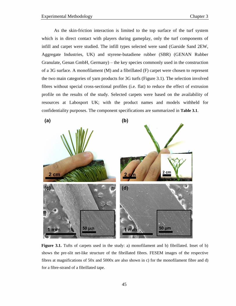
Experimental Methodology Chapter 3
45
As the skin-friction interaction is limited to the top surface of the turf system
which is in direct contact with players during gameplay, only the turf components of
infill and carpet were studied. The infill types selected were sand (Garside Sand 2EW,
Aggregate Industries, UK) and styrene-butadiene rubber (SBR) (GENAN Rubber
Granulate, Genan GmbH, Germany) – the key species commonly used in the construction
of a 3G surface. A monofilament (M) and a fibrillated (F) carpet were chosen to represent
the two main categories of yarn products for 3G turfs (Figure 3.1). The selection involved
fibres without special cross-sectional profiles (i.e. flat) to reduce the effect of extrusion
profile on the results of the study. Selected carpets were based on the availability of
resources at Labosport UK; with the product names and models withheld for
confidentiality purposes. The component specifications are summarized in Table 3.1.
Figure 3.1. Tufts of carpets used in the study: a) monofilament and b) fibrillated. Inset of b)
shows the pre-slit net-like structure of the fibrillated fibres. FESEM images of the respective
fibres at magnifications of 50x and 5000x are also shown in c) for the monofilament fibre and d)
for a fibre-strand of a fibrillated tape.

Experimental Methodology Chapter 3
46
Table 3.1. Product specifications of 3G turf components used in the study
Carpets Material Pile width
(mm)
Pile length
(mm) Tufts/m
2
Fibres/
tuft
Fibres/
m2
Fibre
thickness
(mm)
Monofilament Polyethylene 1 40 26400 12 316800 0.30
Fibrillated Polyethylene 10.5 60 18200 2 36400a
0.10
Infillsb Size range
(mm)
Bulk
densityc
(g/cm3)
Sand 0.71 – 0.25 1.56
Styrene-
butadiene
rubber (SBR)
0.8 – 1.8 0.45
a Each 10.5 mm-wide fibre is pre-slit with 7 staggered slits and when fully split, produces 8 fibre-
strands b Data obtained from technical specification sheets of respective infills
c According to test method ASTM D5603
[15]
3.3.1 Preparation of Test Surfaces
For each carpet type, five surfaces (1 x 1 m) were prepared: carpet-only, sand with
20 mm free-pile height (FPH), SBR with 20 mm FPH, sand with 0 mm FPH and SBR
with 0 mm FPH. The carpets were first raked to lift the fibres which tend to lie inclined in
their intrinsic orientation as a result of the manufacturing process of artificial turf carpets.
This was done by running a 50 cm hand rake through the carpet 20 times on each half,
against the direction of inclination as illustrated in Figure 3.2b. For filled-surfaces, the
determined amount of infill was applied to the surface in three additions with standard
surface conditioning after each addition. Surface conditioning involves the passing of a
hand-pulled studded roller of 28.5 ± 2 kg (118 ± 5 mm diameter) across the test surface
for 50 cycles (to and fro)[9]
.

Experimental Methodology Chapter 3
47
Figure 3.2. a) Image showing the carpet with intrinsic fibre orientation which is prepared for
testing by raking in the direction shown in b).
The 10 surfaces were constructed as follows: carpet-only (M1 and F1), partially
sand-filled (M2 and F2), partially SBR-filled (M3 and F3), fully sand-filled (M4 and F4)
and fully SBR-filled (M5 and F5).
The infill depths and free-pile heights (FPH) of each test surface were measured
and recorded before and after each trial as demonstrated schematically in Figure 3.3. The
test surfaces were reconditioned after each trial, by raking and redistribution of the infill
material to maintain the consistency of initial test conditions of the surfaces. Table 3.2
shows the specifications of the prepared surfaces, where the presented infill depths and
FPH values were averaged over five different readings measured across the 1 m2 surface.
For the fully-filled surfaces (M5 and F5), the nature of the constructed turf system limits
the ability of the surface to be filled evenly to the brim as infill particles above the
maximum pile height will be removed during surface conditioning due to the lack of
carpet fibres to hold them in place.

Experimental Methodology Chapter 3
48
Figure 3.3. Schematic representing the measurement of the infill depth and free-pile height of a
filled 3G turf surface
Table 3.2. Measured specifications of the prepared artificial turf surfaces prior to testing
Surface
system code
Carpet type
(pile length in mm)
Infill type Infill depth (mm) Free-pile height
(mm)
M1 Monofilament (40) None 0.0 40.0a
M2 Monofilament (40) Sand 20.7 ± 0.1 18.0 ± 0.1
M3 Monofilament (40) SBR 22.4 ± 0.2 17.1 ± 0.2
M4 Monofilament (40) Sand 35.3 ± 0.2 3.3 ± 0.2
M5 Monofilament (40) SBR 35.0 ± 0.4 4.2 ± 0.2
F1 Fibrillated (60) None 0.0 60.0a
F2 Fibrillated (60) Sand 33.8 ± 0.1 22.8 ± 0.1
F3 Fibrillated (60) SBR 36.6 ± 0.1 17.0 ± 0.1
F4 Fibrillated (60) Sand 51.0 ± 0.1 3.3 ± 0.1
F5 Fibrillated (60) SBR 52.1 ± 0.1 4.0 ± 0.1 a Full pile-length exposed
Prior to testing, each test surface was photographed to document the component-
coverage on the turf, within a pre-determined area. A 5 mm-thick transparent polymethyl
methacrylate (PMMA) plate marked with a 5 x 5 cm square is placed onto the prepared
surfaces and weights were placed on both ends of the plate to weigh it down – simulating
the foot-surface interface. The set-up was then imaged through the 5 x 5 cm square to
observe the area coverage by individual turf components and sampling was conducted at
three different locations on each 3G turf surface. Image processing was subsequently
carried out with imaging software ImageJ (National Institute of Health, MA, USA) to
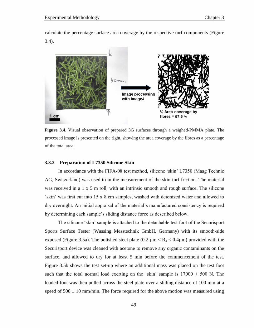
Experimental Methodology Chapter 3
49
calculate the percentage surface area coverage by the respective turf components (Figure
3.4).
Figure 3.4. Visual observation of prepared 3G surfaces through a weighed-PMMA plate. The
processed image is presented on the right, showing the area coverage by the fibres as a percentage
of the total area.
3.3.2 Preparation of L7350 Silicone Skin
In accordance with the FIFA-08 test method, silicone ‘skin’ L7350 (Maag Technic
AG, Switzerland) was used to in the measurement of the skin-turf friction. The material
was received in a 1 x 5 m roll, with an intrinsic smooth and rough surface. The silicone
‘skin’ was first cut into 15 x 8 cm samples, washed with deionized water and allowed to
dry overnight. An initial appraisal of the material’s manufactured consistency is required
by determining each sample’s sliding distance force as described below.
The silicone ‘skin’ sample is attached to the detachable test foot of the Securisport
Sports Surface Tester (Wassing Messtechnik GmbH, Germany) with its smooth-side
exposed (Figure 3.5a). The polished steel plate (0.2 µm < Ra < 0.4µm) provided with the
Securisport device was cleaned with acetone to remove any organic contaminants on the
surface, and allowed to dry for at least 5 min before the commencement of the test.
Figure 3.5b shows the test set-up where an additional mass was placed on the test foot
such that the total normal load exerting on the ‘skin’ sample is 17000 ± 500 N. The
loaded-foot was then pulled across the steel plate over a sliding distance of 100 mm at a
speed of 500 ± 10 mm/min. The force required for the above motion was measured using

Experimental Methodology Chapter 3
50
a tensile measurement machine (Instron 5569, MA, USA) with a 100 N load cell. This
was repeated 10 times and the average force (F4-8) measured between the sliding distance
40 – 80 mm was determined for each trial. The sliding distance force (Fnew) was then
calculated by averaging the ten F4-8 values for each ‘skin’ sample. ‘Skin’ samples were
considered acceptable and selected if their Fnew values fall within the 6 ± 1.5 N range and
the standard deviation of the 10 measurements is less than 0.3.
Figure 3.5. a) L7350 silicone ‘skin’ sample secured to the test foot using double-sided adhesive
and clamping screws. b) Experimental set-up for the determination of the sliding friction force of
each silicone ‘skin’ sample.
3.3.3 ‘Skin’ Friction and Abrasion Trials
3.3.3.1 Securisport Sport Surface Tester
The prepared ‘skin’ samples were secured onto the test foot and subsequently
attached to the Securisport (Figure 3.6), placed on the 1 x 1 m test surface. A normal load
of 100 N was applied via the pneumatic ram. The control software drives the motor to
rotate the foot across the surface at a speed of 40 rpm for five revolutions (each
revolution = 1.5 s). Instead of reporting a single average coefficient of friction (COF)
value as per the FIFA-08 protocol, the raw data files recording the variation of normal

Experimental Methodology Chapter 3
51
load and horizontal torque with time, were saved for further analysis. Three repeat trials
were conducted for every test surface, each with a new ‘skin’ sample.
Figure 3.6. Experimental set-up showing the Securisport device and attached test-foot (inset)
The raw values of normal load and horizontal torque from the Securisport were
passed through a low-pass Butterworth filter, adapted from the built-in function in
computing software MATLAB (MATLAB R2015a, The Mathworks Inc., MA, USA).
This was to remove high frequency data noise, where the filter frequency and selection
were determined based on a power analysis of the signals (details of the MATLAB code
is provided in Appendix 1). The COF was then calculated according to Equation (3.1),
where the radius of rotation for the Securisport is 0.2 m.

Experimental Methodology Chapter 3
52
3.3.3.2 Surface Roughness of Silicone ‘Skin’
In addition to the standard FIFA-08 requirements, surface roughness profiles of the
‘skin’ samples were characterized to further investigate the ‘abrasion’ of the system.
Prior to characterization, the superficial infill or fibre material adhered to the tested ‘skin’
samples were removed using compressed air, followed by ultra-sonication for 10 min in
deionized water and subsequent drying. The 3D scanning was carried out using a surface
profiler (Taylor Jobson Precision Talyscan 150, UK) for a scan area of 2 x 2 mm2 at a
speed of 1000 µm/s using an inductive diamond probe. The root mean square surface
roughness value (Sq) of the scanned area was determined by the Talymap Basic 3.1.2
software, according to Equation (3.2).
The abrasion on the ‘skin’ samples was then determined semi-quantitatively by
assessing the amount of damage from the change in surface roughness of the tested
samples.
3.3.3.3 Statistical Analysis
All statistical analysis were performed using SPSS (v22, SPSS Inc. Chicago, USA).
An independent sample t-test was used to compare the mean change in ‘skin’ surface
roughness between the two unfilled carpets (monofilament and fibrillated), while a three-
way (2 × 2 × 2) analysis of variance (ANOVA) was used to compare the mean change in
‘skin’ surface roughness according to three factors: carpet type (monofilament and
fibrillated), infill type (sand and SBR) and infill depth (half and full). For the ANOVA
analysis, Greenhouse-Geisser adjustment to the degrees of freedom was applied if
sphericity was violated. Cohen’s d effect sizes[16]
were calculated and defined as small (d
≤ 0.2), medium (0.2 < d < 0.8) and large (d ≥ 0.8). Data were presented as mean ±
standard deviation (SD) and statistical significance was set at p < 0.05, unless specified.
COF =Horizontal Torque [Nm]
(Radius of rotation [m]) (Normal Force [N]) (3.1)
Sq = [1
𝐿2∫ ∫ 𝑍(𝑥, 𝑦)2
𝐿
0
𝑑𝑥𝑑𝑦𝐿
0
]
1/2
(3.2)

Experimental Methodology Chapter 3
53
3.4 Surface Modification of Polypropylene to Improve Skin-Friendliness
An experiment protocol was developed to modify the surface properties of the
identified polypropylene (PP) substrate. From the review of literature, surface
functionalization is a popular strategy to impart superior properties to common polymeric
materials; improving their surface properties with minimal effect on the bulk mechanical
properties of the substrate.[17, 18]
In the context of artificial turf fibres, the strength,
resiliency and durability[19–21]
are important fibre parameters that affect the performance
of the overall carpet when tested for player-turf and ball-turf interactions. Therefore,
surface modification via polymer brush grafting can be applied as a post-treatment to
manufactured yarns and fibres, with minimal effect on the pre-optimized mechanical
properties. Polymer brushes have also shown to be versatile to allow for the provision of
specific surface functions through the designing of appropriate polymer grafts.
To address the skin-friendliness of the fibre component of the artificial turf system,
focus was placed on improving the frictional behaviour of the surface and imparting
antifouling properties. With inspiration from the biomedical field where the lubricating
effect of solvated polymer brushes has achieved great advancements in applications such
as joint implants, the mechanism of hydrated lubrication was targeted – narrowing the
selection of polymer candidates to hydrophilic species. Furthermore, this allows for the
desired use of water as a lubricating agent since artificial turf surfaces are often hosed
down before a game[22, 23]
, making water a readily available lubricant.
Correspondingly, the antifouling properties of polymeric coatings are often
attributed to their hydrophilic nature where such polymers, have the ability to bind tightly
to water molecules – forming a hydrated barrier that prevents cells and protein from
accessing the underlying substrate. Hydrophilicity was thus identified as a key criterion
for the selection of polymer brushes that may possess both low friction and antifouling
properties.
Zwitterionic poly(sulfobetaine methacrylate) (pSBMA) has been identified as a
suitable polymer for the modification of the hydrophobic polypropylene substrates. The
charges on the zwitterionic moieties bind water molecules through electrostatic attractive
forces – interactions that are stronger than hydrogen bonds found in most hydrophilic
Experimental Methodology Chapter 3
54
polymers. The biocompatible pSBMA is also known for its antifouling properties where
its protein-resistance is attributed to both the strong binding of water as previously
mentioned, as well as the quaternary ammonium functional group that provides
antimicrobial activity.
To tether the pSBMA brushes onto the PP substrates, the strategy of photoinduced
surface grafting was selected. This method is commonly used in surface graft
polymerizations due to advantages such as fast reaction rates, low production costs and
the ease of scalability for the potential integration into the manufacturing process of
eventual turf fibre yarns[24, 25]
. The following section details the methodologies used to
modify the surface properties of PP substrate with pSBMA brushes through photoinduced
surface grafting.
3.4.1 Materials
Commercially polypropylene films of 0.03 mm were purchased (Goodfellow Inc,
Cambridge, UK) and cut into samples of 0.3 cm by 2.5 cm. The samples were cleaned
three times using acetone, under ultrasonication (Elmasonic S90H, Germany) to remove
any organic contaminants. The washed samples were then dried at room temperature (25
C) overnight prior to the modification reactions. Sulfobetaine methacrylate (SBMA)
monomer and photoinitiator benzophenone (BP) (Sigma-Aldrich, Singapore) were used
as received. Analytical grade acetone (99.98%) (Fisher Scientific, Singapore) and Milli-Q
grade deionized water (Milli-Q Integral, Merck Millipore, Germany) were used for the
preparation of solutions. Sodium cacodylate buffer, glutaraldehyde solution (Sigma-
Aldrich, Singapore) and analytical grade ethanol (99.9%) (Merck, Singapore) were used
in the fixation of cells and preparation of samples for electron microscopy.
3.4.2 Photoinduced Grafting of pSBMA
The photoinduced grafting protocol was adapted from the approach used by Yang
and Ranby[26–28]
. A series of monomer solutions of varying concentrations of 0.05 M,
0.10 M and 0.20 M were prepared by dissolving SBMA in degassed deionized water. The
photoinitiator solutions of 1 wt%, 5 wt% and 10 wt% (0.48 M) were prepared by
dissolving BP crystals in analytical grade acetone in the dark and stored in ultraviolet

Experimental Methodology Chapter 3
55
(UV)-resistant bottles prior to the experiments. The samples were prepared in a dark
room and only exposed to UV irradiation during the reaction process.
The PP substrates were submerged in the BP solution for 30 min to allow for the
physiosorption of the photoinitiators onto the substrate surfaces. The BP-treated
substrates were then dried in the dark for 4 h to allow for complete evaporation of the
solvent. A 100 µL-drop of SBMA solution was then deposited onto the BP-treated
substrate using a micropipette and a pristine PP film of the same dimensions was
subsequently placed on top of the droplet, forming a sandwich structure as illustrated in
Figure 3.7. The sandwich assembly was then placed into the UV chamber (Incure F200P
UV Flood Curing Lamp, Blaze Technology, Singapore) and irradiated with a metal halide
lamp (600W), at an irradiation intensity of 50 mW/cm2 (±5 mW/cm
2). The irradiation
durations were varied at intervals of 300 s, from 0 – 1200 s to study the effect of
irradiation time on extent of surface modification.
Figure 3.7. Schematic of photoinduced grafting of the pSBMA-grafted PP samples
The reacted sandwich structure was delaminated in hot (70°C) deionized water and
the top PP film was discarded. The bottom modified PP substrates were washed
thoroughly with hot deionized water to remove homopolymers and residual monomers.
The washed samples were then dried in vacuo overnight and stored in desiccators for
further characterizations and analyses.
3.4.3 Material Characterization
Characterization techniques are required to firstly, determine if the substrate has
been modified successfully and thereafter, the extent of modification. Next, techniques of
surface imaging and topographical analyses are needed to validate that the introduced
material exists in the form of grafted brushes. Identification techniques are then required

Experimental Methodology Chapter 3
56
to verify the chemical identity of the grafted material to achieve the intended pSBMA-
grafted-PP samples. These objectives are fulfilled via the various selected
characterization techniques as detailed in the following sections.
3.4.3.1 Gravimetric Analysis
The grafting of pSBMA onto the PP substrates was quantified by gravimetric
methods where the mass gain from photoinduced pSBMA-grafting was recorded. The
initial dry mass (M0) and final dry mass (M) of the samples were measured using a
microbalance, where M denotes the mass of the sample after thorough washing and
drying. The grafting density (GD) was then calculated using Equation (3.3) where A is
the surface area of the substrate exposed to UV irradiation. A set of five samples per
condition (BP-SBMA concentrations) was prepared and measured accordingly to provide
representative results.
GD = (M − M0
A) (3.3)
3.4.3.2 Contact Angle Measurement
The hydrophilicity of the modified PP substrates were characterized by their water
contact angles (OCA 15Pro, DataPhysics, Instruments GmbH, Germany). The wettability
of a surface is determined by its water contact angle, where a smaller angle denotes that
spreading of water on the surface is favourable and hence, more hydrophilic. On the other
hand, surfaces with contact angles that are larger than 90 indicates hydrophobicity where
the water forms a compact droplet so as to minimize contact with the surface[29]
.
Measurements were conducted with 6 µL water droplets dozed at a rate of 1 µL/s. The
contact angle measurements were repeated three times for each sample.
3.4.3.3 Field-emission Scanning Electron Microscopy (FESEM)
The sample surfaces were imaged using a field-emission scanning electron
microscope (FESEM, JSM-7600F, JEOL Co., Tokyo, Japan). The FESEM uses the
bombardment of electrons onto a surface to visualize topographical details. Primary
electrons liberated from a field-emission source are accelerated at high velocities and
focused onto the sample surface, scanning the surface in a zig-zag manner. With the

Experimental Methodology Chapter 3
57
incidence of the primary electron beam, secondary electrons are emitted from the sample
surface with varying speeds and directions of travel, dependent on the surface topography
of the sample. The secondary electrons are collected by the detector and produce
electrical signals that are converted to a two-dimensional image.
The dried samples were platinum sputtered at 20 mA for 45 s (JEOL JFC-1600) to
coat the polymeric samples with a 20 nm-thick conductive layer. The prepared samples
were then imaged at an accelerating voltage of 5 kV, at a magnification of 10000x.
3.4.3.4 Atomic Force Microscopy (AFM)
The surface topographies of the samples were imaged using the Atomic Force
Microscope (Cypher S, Asylum Research, CA, USA). The AFM imaging was conducted
in tapping mode, where a mechanically oscillated cantilever is moved across the sample
surface. The cantilever is driven at a frequency near its resonance frequency, via a
piezoelectric actuator. Deflection in the cantilever tip as it moves across the topological
features of the surface is registered by the optical lever detector which monitors the
position of a reflected laser beam incident on the moving cantilever. The corresponding
change in oscillating amplitude of the tip, together with its phase difference with respect
to the driving frequency can be measured. The tapping mode is preferred over the contact
and non-contact modes as it eliminates frictional and adhesive forces through intermittent
breaking of tip-contact with the sample surface, yet provides sufficient interaction to
provide an accurate representation of the surface[30]
.
The modified PP substrates were cut to size and secured onto magnetic sample
holders. The samples were subsequently loaded onto the magnetic stage in the AFM
chamber. Scanning was conducted at a rate of 1 Hz for a scan size of 2 x 2 µm. The
cantilever used in the measurement was a monolithic aluminium-coated silicon probe
(Arrow-NCR-50, Nanoworld, Switzerland). Further image analysis was performed using
the Igor Pro Software developed by WaveMetrics. The samples were scanned at least
three times to ensure representative quantitative data of the surfaces.

Experimental Methodology Chapter 3
58
3.4.3.5 Fourier Transform Infrared Spectroscopy – Attenuated Total Reflectance
(FTIR-ATR)
The FTIR-ATR (Frontier, Perkin Elmer, MA, USA) was used to characterize the
grafted samples by detecting the presence of key compounds on the modified surfaces[31]
.
The FTIR works on the principle of identifying compounds based on their characteristic
infrared spectrums. The prepared sample is incident with an infrared beam of designated
wavelength range; and a detector on the other side of the sample collects and analyses the
exiting signal to produce an absorption versus wavelength plot known as the infrared
spectrum. Absorption peaks on the infrared spectrum correspond to the vibration
frequencies of individual bond types present in the analysed material. As materials
consist of unique combinations of bonded atoms, FTIR can hence be used to identify
different materials.
Beneficially, the FTIR-ATR overcomes the challenges faced in traditional FTIR,
bypassing the need for complicated sample preparation thus eliminating random errors
and hence improving spectral reproducibility. The ATR involves the incidence of the
infrared beam into an optically dense crystal (diamond) which results in totally internally
reflection due to the high refractive index of the crystal (illustrated in Figure 3.8). The
evanescent wave created by the total internal reflection extends beyond the crystal
surface (0.5 – 5 µm), into the sample which is held in firm contact with the ATR crystal
by a normal load. Changes in the evanescent wave due to interaction with the material
results in attenuation in the beam signal which is identified by the detector. The FTIR-
ATR is therefore a non-destructive characterization method suitable for the surface
analysis of the modified PP substrates.
Figure 3.8. Schematic of a multiple-reflection FTIR-ATR system

Experimental Methodology Chapter 3
59
Prior to and between every FTIR-ATR analysis, the diamond crystal is cleaned
with ethanol to remove contaminants. A background scan is then collected. The PP
samples were subsequently placed onto the diamond crystal, with the modified surface
covering and in contact with the crystal. The pressure arm of the Frontier equipment was
then positioned over the sample and a normal force of 100N (indicated on the force gauge)
was applied to ensure contact between the sample and crystal. Scanning was carried out
from 4000 cm-1
to 650 cm-1
for 16 scans with a resolution of 2cm-1
.
3.4.3.6 X-ray Photoelectron Spectroscopy (XPS)
Analysis of surface elemental composition of the samples was carried out using
XPS (AXIS Supra, Kratos Analytical Ltd, UK). This was done by irradiating the sample
surface with an X-ray beam, provoking the photoelectric effect where electrons are
emitted from the excited sample surface. The electrons are ejected with characteristic
kinetic energy (KE) levels dependent on their source atoms, from which the
corresponding binding energies (BE) can be computed using Equation(3.4) (where
represents the working function of the XPS). The photoelectron spectrum represents the
count of ejected electrons across a range of binding energies, where peak energy and
intensities are analysed to enable the identification and quantification of surface elements.
BE = h𝜈 − KE − 𝜙 (3.4)
For analysis of the pSBMA-g-PP samples, the samples were mounted onto a glass
slide and XPS analysis was performed using a monochromatic Al Kα excitation source
(hυ = 1486.71 eV, nominal operating voltage of 15 kV and maximum current of 40 mA).
Elemental composition of the sampled surface was identified from a survey scan from
1200 to 0 eV, and the corresponding five region scans were collected from each sample.
The region scans were the O 1s (550 – 515 eV), C 1s (305 – 270 eV), Si 2p (105 – 90 eV),
S 2p (175 – 160 eV) and N 1s (385 – 410 eV). The binding energy scale was then
referenced by setting the peak maximum in the C 1s spectrum for adventitious carbon to
be at 284.8 eV. The high resolution spectra for each identified element were fitted using a
Shirley background subtraction and a series of Gaussian peaks to determine the various
chemical states, with analysis carried out on the CasaXPS Version 2.3.15 software.

Experimental Methodology Chapter 3
60
3.4.3.7 Differential Scanning Calorimetry (DSC)
The DSC (Q10, TA Instruments, DE, USA) was used to characterize the surface
water adsorbed onto the samples.[32, 33]
The encapsulated sample is placed in the DSC
chamber together with an inert reference. Heat energy is supplied or removed at a
determined rate, to the chamber and the difference in heat flow between the sample and
reference is measured as a function of time and temperature[34]
. When a change in energy
is registered as the sample is heated, cooled or held isothermally, a change in gradient
such as a step or a peak feature is reflected on the heat flow curve – recording the time
and temperature at which the change occurs and providing quantitative information as
well. The DSC is hence a useful equipment for the analysis of thermal transitions of
materials, with minimal sample preparation and easy equipment operation.
Before analysis, the system is heated to and held isothermal at 300C for 5 min to
burn off any organic contaminants present in the chamber. The DSC analysis is carried
out by preparing the samples in accordance to the following method. The modified
samples were cut to size allowed to equilibrate in deionized water overnight. The
hydrated samples were retrieved and excess surface water was removed by lightly drying
on a piece of filter paper. The hydrated samples were placed in pre-weighed aluminium
hermetic DSC pans and immediately sealed and weighed again to obtain the hydrated
mass of the samples (Mhyd).
The sealed hermetic pan was then loaded into the DSC chamber together with a
reference (empty, sealed aluminium hermetic pan). The samples were cooled to -60C at
a rate of 2.5C/min, held isothermal for 2 min and then heated to 60C at 2.5C/min. The
transition enthalpy (H) for the melting of frozen water was calculated using the TA
Universal Analysis software.
After the DSC trials, the pans were punctured and dried overnight in an oven at
120C to allow complete evaporation of water from the pan. The dry mass of the samples
were then determined (Mdry) and the total water content (Mtot) of each sample calculated
according to Equation (3.5). The amount of freezable water (Mf) was calculated from the
H values, with the assumption that the latent heat of fusion of ice is -334.45 J/g. The

Experimental Methodology Chapter 3
61
non-freezable water content (Mnf) was then determined using Equation (3.6). All DSC
experiments were repeated at least twice.
3.5 Skin-Friendliness Assessment of pSBMA-Modified Substrates
The skin-friendliness of the modified samples were determined by their friction-
reduction properties when tested using skin-like silicone rubber and their antifouling
properties against pathogenic bacteria Staphylococcus aureus (S. aureus).
3.5.1 Frictional Properties measured using L7350
In this project, the abrasiveness of a surface is related directly to its frictional
interaction with skin. Excessive friction may lead to the removal of superficial epidermal
cells[35]
and/or lesion of the epidermis to expose underlying tissue[36–38]
hence forming an
open wound known as an abrasion.
To investigate the frictional property of the modified samples with respect to their
skin-friendliness, a bench-top study was designed. This was in place of in vivo studies on
live subjects due to ethical considerations and the large variability in skin properties[10–12,
14] as documented by past studies. Instead, the FIFA-approved L7350 silicone skin was
selected as the counter-surface for the tribological measurements as it is currently used by
the football governing body in industrial certification of the skin-abrasiveness of artificial
turfs. Furthermore, silicone provides the closest frictional behaviour to human skin[39]
and
is a common base material used in the manufacturing of skin surrogates for biological
applications[40]
. The selection of a standard counter-surface contributes to the
repeatability of the test method.
The coefficient of friction (µ) of the samples were measured using a pin-on-disk
microtribometer (CSM Instruments SA, Switzerland) (Figure 3.9) using hemispherical (1
cm diameter) tips of L7350 silicone skin (Maag Technic AG, Switzerland). Frictional
measurements were carried out at room temperature (25C) with a normal load of 0.2 N,
rotational radius of 1.00 mm and linear speed of 5 cm/s for 300 revolutions. The test
Mtot = Mhyd − Mdry (3.5)
Mnf = Mtot − Mf , Mf = ∆𝐻
(−334.45) (3.6)

Experimental Methodology Chapter 3
62
parameters were selected to produce contact pressures similar to the estimated values
experienced by players when they perform sliding tackles on artificial turf surfaces
(Appendix 2).
A key strategy towards skin-friendly surfaces was the modification with
hydrophilic polymer brushes. Hence, to investigate the effectiveness of hydration on
reducing the skin-friction of the samples, tribological studies were performed under both
dry and hydrated states. Hydrated samples were prepared by submerging in deionized
water for 2 h and the excess surface water was removed using a piece of filter paper prior
to testing. This was to simulate real field-conditions where playing surfaces are often
watered before the commencement of a game, yet a sub-surface drainage system
discharges accumulated water to prevent undesired pooling[22, 23]
. The tribological data
was then processed with graphing software (OriginPro 8.5, OriginLab, MA, USA) for
subsequent analysis.
Figure 3.9. Microtribometer used in the frictional assessment of the modified PP substrates.
3.5.2 Bioassay against Staphylococcus aureus
In addition to discomfort and bleeding, an abrasion wound acts as a point of entry
for bacteria[41]
, potentially leading to infections and complications. Hence the anti-fouling
properties of the modified samples were evaluated in accordance to common bioassay
procedures[42, 43]
with pathogenic Staphylococcus aureus (S. aureus) bacteria. S. aureus

Experimental Methodology Chapter 3
63
was selected due to its well-documented association with skin infections[44, 45]
and the
prevalence of S. aureus outbreaks within the sporting community[46–48]
.
The gram positive S. aureus cells were cultured overnight in tryptic soy broth
(37°C) and the resulting suspension was centrifuged to remove the supernatant. The cells
were then re-suspended in phosphate-buffered saline (PBS) to a concentration of 108
cells/mL. PBS-soaked PP samples were immersed in 2 mL of the bacteria suspension at
room temperature (25°C) for 4 h. The samples were then removed and rinsed repeatedly
for three times, to remove the un-adsorbed cells. The adhered bacteria cells were
fixated[49, 50]
with 2.5 v/v% glutaraldehyde for 1 h followed by repeated washing with 1
v/v% sodium cacodylate and dehydrated with serial ethanol solutions of 5, 10, 25, 50, 75,
90, 95 and 100 v/v% for 15 min each prior to freeze-drying for at least 24 h. The dried
samples were then imaged using FESEM as per Section 3.4.3.3. The FESEM images
were further processed using imaging software ImageJ (National Institutes of Health, MA,
USA) to semi-quantify the antifouling properties through determination of the area
coverage by adhered bacteria cells.
3.6 Importance of Tribo-tip Selection in Relation to Skin-Friendliness
The lack of a standard skin model or counter-surface limits the effectiveness of
using frictional assessment to qualify the skin-friendliness of sport surfaces. This concern
is investigated by modifying the tribological study presented in Section 3.5.1., to compare
the difference in results obtained from using alternative tribo-tips.
To demonstrate the influence of counter-surface on the effective measured
frictional properties of surfaces, the coefficient of friction (µ) of the pSBMA-grafted PP
samples were measured under the same conditions (dry and hydrated) as previously
recorded, but using 1 cm-diameter spherical standard AISI 440 stainless steel (SS) tribo-
tips instead. SS was selected as the material for comparison as it is commonly used as the
assessing counter-surface in tribological studies[51–54]
. In addition, to study the effect of
test time on the frictional profiles, the trials were conducted for both 300 revolutions and
for an extended 2000 revolutions.

Experimental Methodology Chapter 3
64
3.7 Summary
This chapter has detailed the research methodology, materials and test procedures
developed and used in the experimental programme of this research project. In order to
achieve the project aims and objectives, the work was split into macro-scale turf testing
and micro-scale material testing.
To understand the component-contribution of the 3G turf system to its overall
frictional skin-surface behaviour, the frictional profiles of various 3G surfaces were
monitored. A combination of turf components and surface build-up specifications were
used to present a systematic study. Following from this, the key component that has the
largest influence on overall skin-surface friction was determined and helped identify the
substrate to be targeted for the subsequent section.
Material modification of the identified substrate was then carried out with the
objective to improve its skin-friendliness properties. The strategy of photoinduced
surface grafting was chosen based on economic considerations, where the process can be
easily integrated into the existing yarn production lines. Poly(sulfobetaine methacrylate)
was grafted to provide both reduced friction and antifouling properties. The skin-
friendliness was then assessed based on their frictional behaviour against commercially
used silicone skin and resistance to surface adsorption by pathogenic S. aureus bacteria.
As part of the greater objective to address the skin-friendliness of artificial turf
surfaces, the influence of counter-surface in friction assessments was investigated. The
frictional properties of previously modified samples were compared using both stainless
steel and silicone skin tribological tips. The study seeks to highlight how the selection of
tips may affect the conclusions drawn on the frictional properties and their implications
on skin-friendliness of surfaces.
The results of the above sections are presented and discussed in the following
chapters.
3.8 References
[1] Fédération Internationale de Football Association (FIFA), FIFA Quality Concept
Requirements Manual, 2012.
[2] International Rugby Board, IRB Artificial Rugby Turf Performance Specification:

Experimental Methodology Chapter 3
65
One Turf Technical Manual, 2012.
[3] C.W. Fuller, L. Clarke, and M.G. Molloy, Risk of injury associated with rugby
union played on artificial turf. J. Sports Sci. 2010, 28, 563–570.
[4] C.W. Fuller, R.W. Dick, J. Corlette, and R. Schmalz, Comparison of the
incidence, nature and cause of injuries sustained on grass and new generation artificial
turf by male and female football players. Part 2: training injuries. Br. J. Sports Med. 2007,
41 Suppl 1, i27–32.
[5] M.C. Meyers and B.S. Barnhill, Incidence, causes, and severity of high school
football injuries on FieldTurf versus natural grass: a 5-year prospective study. Am. J.
Sports Med. 2004, 32, 1626–1638.
[6] P. Burillo, L. Gallardo, J.L. Felipe, and A.M. Gallardo, Artificial turf surfaces:
Perception of safety, sporting feature, satisfaction and preference of football users. Eur. J.
Sport Sci. 2014, 14, S437–S447.
[7] J. Roberts, P. Osei-Owusu, A. Harland, A. Owen, and A. Smith, Elite Football
Players’ Perceptions of Football Turf and Natural Grass Surface Properties. Procedia Eng.
2014, 72, 907–912.
[8] E.M. Zanetti, Amateur football game on artificial turf: players’ perceptions. Appl.
Ergon. 2009, 40, 485–490.
[9] Fédération Internationale de Football Association (FIFA), FIFA Quality Concept
for Football Turf - Handbook of Test Methods, 2012.
[10] N. Gitis and R. Sivamani, Tribometrology of Skin. Tribol. Trans. 2004, 47, 461–
469.
[11] R.K. Sivamani and H.I. Maibach, Tribology of skin. Proc. Inst. Mech. Eng. Part J
J. Eng. Tribol. 2006, 220, 729–737.
[12] S. Derler and L.-C. Gerhardt, Tribology of Skin: Review and Analysis of
Experimental Results for the Friction Coefficient of Human Skin. Tribol. Lett. 2012, 45,
1–27.
[13] A.F. El-Shimi, In vivo skin friciton measurements. J. Soc. Cosmet. Chem. 1977,
28, 37–51.
[14] C. Pailler-Mattei, S. Pavan, R. Vargiolu, F. Pirot, F. Falson, and H. Zahouani,
Contribution of stratum corneum in determining bio-tribological properties of the human
Experimental Methodology Chapter 3
66
skin. Wear 2007, 263, 1038–1043.
[15] ASTM International, ASTM Standard D 5603, 2015. Stand. Classif. Rubber
Compd. Mater. - Recycl. Vulcanizate Part. Rubber 2015.
[16] J. Cohen, A power primer. Psychol. Bull. 1992, 112, 155–159.
[17] B. Kolgjini, G. Schoukens, and P. Kiekens, Influence of Stretching on the
Resilience of LLDPE Monofilaments for Application in Artificial Turf. J. Appl. Polym.
Sci. 2012, 124, 4081–4089.
[18] B. Kolgjini, G. Schoukens, I. Kola, S. Rambour, E. Shehi, and P. Kiekens,
Influence of Heat Treatment on the Bending Behaviour of LLDPE Monofilaments. Autex
Res. J. 2014, 14, 187–199.
[19] P. Sandkuehler, E. Torres, and T. Allgeuer, Polyolefin materials and technology
in artificial turf I: Yarn developments. Sport. Technol. 2010, 3, 52–58.
[20] P. Sandkuehler, E. Torres, and T. Allgeuer, Performance artificial turf
components — fibrillated tape, in: Procedia Engineering, Elsevier, 2010, pp. 3367–3372.
[21] N.J. McLaren, P.R. Fleming, and S. Forrester, Artificial grass: A longitudinal
study on ball roll and free pile height, in: Procedia Engineering, Elsevier B.V., 2014, pp.
871–876.
[22] K. Severn, Science of Synthetic Turf Surfaces: Player–Surface Interactions,
Loughborough University, 2010.
[23] A.J. McLeod, The management and maintenance of second generation sand-filled
synthetic sports pitches, School of Applied Sciences, 2008.
[24] J. Deng, L. Wang, L. Liu, and W. Yang, Developments and new applications of
UV-induced surface graft polymerizations. Prog. Polym. Sci. 2009, 156–193.
[25] B. Ranby, Surface modification and lamination of polymers by photografting. Int.
J. Adhes. Abrasives 1999, 19, 337–343.
[26] W.T. Yang and B. Ranby, Bulk surface photografting process and its applications.
I. Reactions and kinetics. J. Appl. Polym. Sci. 1996, 62, 533–543.
[27] W.T. Yang and B. Ranby, Bulk surface photografting process and its applications.
II. Principal factors affecting surface photografting. J. Appl. Polym. Sci. 1996, 62, 545–
555.
[28] B. Ranby, W.T. Yang, and O. Tretinnikov, Surface photografting of polymer

Experimental Methodology Chapter 3
67
fibers, films and sheets. Nucl. Instruments Methods Phys. Res. Sect. B Beam Interact.
with Mater. Atoms 1999, 151, 301–305.
[29] Y. Yuan and T.R. Lee, Surface Science Techniques, Springer Berlin Heidelberg,
Berlin, Heidelberg 2013.
[30] R. Reifenberger, Introduction to Scanning Probe Microscopy, in: Fundamentals
of Atomic Force Microscopy, World Scientific, 2015, pp. 1–20.
[31] PerkinElmer Inc., FT-IR Spectroscopy Attenuated Total Reflectance (ATR).
PerkinElmer Life Anal. Sci. 2005, 1–5.
[32] C. Zhao, J. Zhao, X. Li, J. Wu, S. Chen, Q. Chen, Q. Wang, X. Gong, L. Li, and J.
Zheng, Probing structure-antifouling activity relationships of polyacrylamides and
polyacrylates. Biomaterials 2013, 34, 4714–4724.
[33] F.M. Plieva, M. Karlsson, M.-R. Aguilar, D. Gomez, S. Mikhalovsky, and I.Y.
Galaev’, Pore structure in supermacroporous polyacrylamide based cryogels. Soft Matter
2005, 1, 303–309.
[34] P. Gabbott, Principles and Applications of Thermal Analysis, Blackwell
Publishing Ltd, Oxford, UK 2008.
[35] W.F. Bergfeld and J.S. Taylor, Trauma, sports, and the skin. Am. J. Ind. Med.
1985, 8, 403–413.
[36] G. Eiland and D. Ridley, Dermatological Problems in the Athlete. J. Orthop.
Sport. Phys. Ther. 1996, 23, 388–402.
[37] A. Metelitsa, B. Barankin, and A.N. Lin, Diagnosis of sports-related dermatoses.
Int. J. Dermatol. 2004, 43, 113–119.
[38] R.S.W. Basler, C.M. Hunzeker, and M.A. Garcia, Athletic Skin Injuries:
Combating Pressure and Friction. Phys. Sportsmed. 2004, 32, 33–40.
[39] M. Zhang and A.F.T. Mak, In vivo friction properties of human skin. Prosthet.
Orthot. Int. 1999, 23, 135–141.
[40] C. Lucarotti, C. Oddo, N. Vitiello, and M. Carrozza, Synthetic and Bio-Artificial
Tactile Sensing: A Review. Sensors 2013, 13, 1435–1466.
[41] M. Pecci, D. Comeau, and V. Chawla, Skin conditions in the athlete. Am. J.
Sports Med. 2009, 37, 406–418.
[42] X. Ding, C. Yang, T.P. Lim, L.Y. Hsu, A.C. Engler, J.L. Hedrick, and Y.-Y.

Experimental Methodology Chapter 3
68
Yang, Antibacterial and antifouling catheter coatings using surface grafted PEG-b-
cationic polycarbonate diblock copolymers. Biomaterials 2012, 33, 6593–6603.
[43] M. Li, K.G. Neoh, L.Q. Xu, R. Wang, E. Kang, T. Lau, D.P. Olszyna, and E.
Chiong, Surface modification of silicone for biomedical applications requiring long-term
antibacterial, antifouling, and hemocompatible properties. Langmuir 2012, 28, 16408–
16422.
[44] L.G. Harris, S.J. Foster, and R.G. Richards, An introduction to Staphylococcus
aureus, and techniques for identifying and quantifying S. aureus adhesisn in relation to
adhesion to biomaterials: Review. Eur. Cells Mater. 2002, 4, 39–60.
[45] J.N. Baumgartner, C.Z. Yang, and S.L. Cooper, Physical property analysis and
bacterial adhesion on a series of phosphonated polyurethanes. Biomaterials 1997, 18,
831–7.
[46] E.M. Begier, K. Frenette, N.L. Barrett, P. Mshar, S. Petit, D.J. Boxrud, K.
Watkins-Colwell, S. Wheeler, E.A. Cebelinski, A. Glennen, D. Nguyen, and J.L. Hadler,
A high-morbidity outbreak of Methicillin-Resistant Staphylococcus aureus among
players on a college football team, facilitated by cosmetic body shaving and turf burns.
Clin. Infect. Dis. 2004, 39, 1446–1453.
[47] A. Grosset-Janin, X. Nicolas, and A. Saraux, Sport and infectious risk: a
systematic review of the literature over 20 years. Médecine Mal. Infect. 2012, 42, 533–44.
[48] A.S. McNitt and D. Petrunak, Survival of Staphylococcus aureus on synthetic turf,
2008.
[49] P. Allan-Wojtas, L. Truelstrup Hansen, and A.T. Paulson, Microstructural studies
of probiotic bacteria-loaded alginate microcapsules using standard electron microscopy
techniques and anhydrous fixation. LWT - Food Sci. Technol. 2008, 18, 101–108.
[50] R. Lamed, J. Naimark, E. Morgenstern, and E. a Bayer, Specialized cell surface
structures in cellulolytic bacteria. J. Bacteriol. 1987, 169, 3792–3800.
[51] K.L. Gilley, J.C. Nino, Y.W. Riddle, D.W. Hahn, and S.S. Perry, Heat treatments
modify the tribological properties of nickel boron coatings. ACS Appl. Mater. Interfaces
2012, 4, 3069–3076.
[52] S.M. Shanta, G.J. Molina, and V. Soloiu, Tribological Effects of Mineral-Oil
Lubricant Contamination with Biofuels: A Pin-on-Disk Tribometry and Wear Study. Adv.

Experimental Methodology Chapter 3
69
Tribol. 2011, 2011, 1–7.
[53] S. Zhang, Biological and Biomedical Coatings Handbook: Applications, CRC
Press, 2011.
[54] K. Holmberg and A. Matthews, Coatings Tribology: Properties, Mechanisms,
Techniques and Applications in Surface Engineering, 2nd ed., Elsevier Science, 2009.

Experimental Methodology Chapter 3
70

Mechanical Assessment of Skin-Turf Friction Chapter 4
71
Chapter 4
Mechanical Assessment of Skin-Turf Friction
This chapter presents the results from the assessment of skin-turf
friction using the Securisport mechanical testing device and provides a
detailed analysis of the frictional behaviours of a series of artificial turf
surfaces, identifying the major component contributing to the overall friction.
An evaluation of the test device on its effectiveness to measure and compare
the skin-surface frictional behaviour of artificial turfs is also presented to
objectively critique the current technology and provide insights to how to
further develop the mechanical assessment of skin-surface friction.

Mechanical Assessment of Skin-Turf Friction Chapter 4
72
4.1 Introduction
This chapter presents the findings of the assessment of skin-turf friction using the
mechanical device – Securisport Sport Surface Tester. Test surfaces were constructed
with varying infill depths, species and carpet types (specifications of the prepared
surfaces are summarized in Table 3.2). The visual observations of the prepared surfaces
is presented in Figure 4.1, showing the surface area coverage by individual turf
components as summarized in Figure 4.1b. A series of controlled laboratory testing was
carried out to analyse the change in coefficient of friction of the ‘skin’-attached test foot
when interacting with the designed test surfaces. Changes in the physical characteristics
of the test surfaces as well as the surface roughness of the ‘skin’ samples were also
measured.
The observations and data are examined in this chapter, followed by detailed
discussion of the key findings and their significances; providing insights to the effect of
the turf components on the overall frictional behaviour and abrasiveness of the test
surfaces. The achieved range of frictional behaviours as well as the independent
measurements of ‘skin’ roughness pre- and post-Securisport testing provide a relevant
dataset for the subsequent evaluation of the Securisport Sports Surface Tester as a means
to measure skin-surface frictional behaviour of artificial turfs.
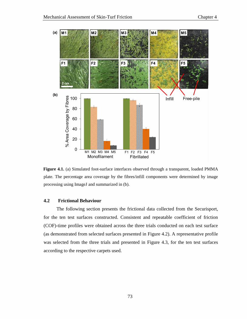
Mechanical Assessment of Skin-Turf Friction Chapter 4
73
Figure 4.1. (a) Simulated foot-surface interfaces observed through a transparent, loaded PMMA
plate. The percentage area coverage by the fibres/infill components were determined by image
processing using ImageJ and summarized in (b).
4.2 Frictional Behaviour
The following section presents the frictional data collected from the Securisport,
for the ten test surfaces constructed. Consistent and repeatable coefficient of friction
(COF)-time profiles were obtained across the three trials conducted on each test surface
(as demonstrated from selected surfaces presented in Figure 4.2). A representative profile
was selected from the three trials and presented in Figure 4.3, for the ten test surfaces
according to the respective carpets used.
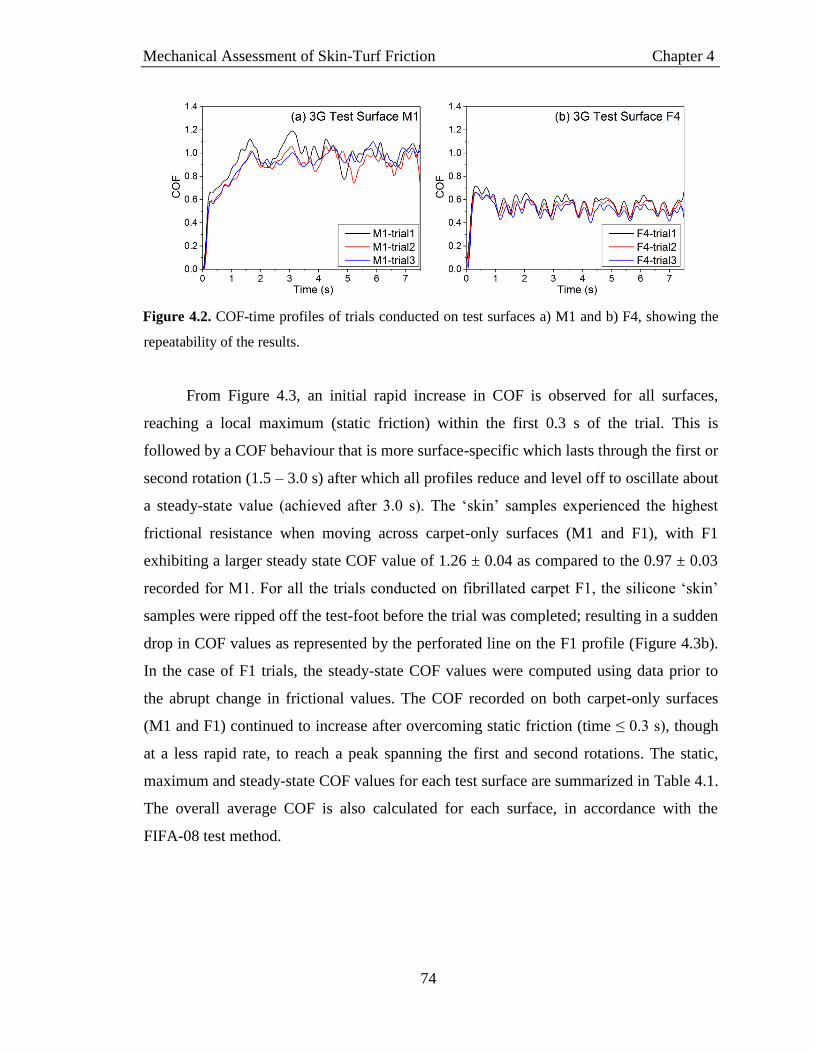
Mechanical Assessment of Skin-Turf Friction Chapter 4
74
Figure 4.2. COF-time profiles of trials conducted on test surfaces a) M1 and b) F4, showing the
repeatability of the results.
From Figure 4.3, an initial rapid increase in COF is observed for all surfaces,
reaching a local maximum (static friction) within the first 0.3 s of the trial. This is
followed by a COF behaviour that is more surface-specific which lasts through the first or
second rotation (1.5 – 3.0 s) after which all profiles reduce and level off to oscillate about
a steady-state value (achieved after 3.0 s). The ‘skin’ samples experienced the highest
frictional resistance when moving across carpet-only surfaces (M1 and F1), with F1
exhibiting a larger steady state COF value of 1.26 ± 0.04 as compared to the 0.97 ± 0.03
recorded for M1. For all the trials conducted on fibrillated carpet F1, the silicone ‘skin’
samples were ripped off the test-foot before the trial was completed; resulting in a sudden
drop in COF values as represented by the perforated line on the F1 profile (Figure 4.3b).
In the case of F1 trials, the steady-state COF values were computed using data prior to
the abrupt change in frictional values. The COF recorded on both carpet-only surfaces
(M1 and F1) continued to increase after overcoming static friction (time ≤ 0.3 s), though
at a less rapid rate, to reach a peak spanning the first and second rotations. The static,
maximum and steady-state COF values for each test surface are summarized in Table 4.1.
The overall average COF is also calculated for each surface, in accordance with the
FIFA-08 test method.

Mechanical Assessment of Skin-Turf Friction Chapter 4
75
Figure 4.3. COF against time profiles of a) monofilament surfaces M1 to M5 and b) fibrillated
surfaces F1 to F5. Vertical lines demarcate the five rotations, at intervals of 1.5 s each.
It was observed that the steady-state COF values of the surfaces increase with free
pile height (FPH), where fully-filled surfaces showed the lowest COF values and unfilled
surfaces have the highest skin-surface friction for each of the carpet-sets. Interestingly,
the COF profiles of the fully-filled surfaces M4, M5, F4 and F5 behave almost identically

Mechanical Assessment of Skin-Turf Friction Chapter 4
76
– with their steady-state COF values converging to a value of 0.57 ± 0.03 – independent
of the carpet or infill type used.
For the monofilament surfaces, M2 which was partially-filled with sand exhibited
a gradual increase in COF after overcoming static friction – to oscillate about the steady-
state value of 0.78 ± 0.02. On the other hand, the COF profile of M3 shows an initial
broad peak similar to that observed for surface M1 which spans the first and second
rotation, before decreasing to the steady-state value of 0.75 ± 0.02.
Both partially-filled fibrillated surfaces F2 and F3 displayed COF profiles with
distinctive initial peaks that coincide with the high-frictional behaviour of surface F1. It
was also observed that the high-frictional effect of the fibrillated fibres (of F1) has
varying extents of influence on the partially-filled surfaces, where the distinctive peaks
appear to be more pronounced in the SBR-filled surface F3 as compared to sand-filled F2.
Table 4.1. Summary of the averaged static, maximum and steady-state COF values recorded for
each test surface. The overall average COF values calculated in accordance with the FIFA-08
Test Methodology is also presented.
Test Surface Static COF Maximum COF Steady-state
COF
Overall
Average COF
(FIFA-08)
M1 0.61 ± 0.03 1.12 ± 0.05 0.97 ± 0.02 0.91* ± 0.03
M2 0.53 ± 0.02 0.91 ± 0.05 0.78 ± 0.02 0.74 ± 0.01
M3 0.56 ± 0.02 0.98 ± 0.05 0.75 ± 0.02 0.73 ± 0.02
M4 0.72 ± 0.01 0.78 ± 0.07 0.59 ± 0.01 0.59 ± 0.01
M5 0.70 ± 0.02 0.71 ± 0.01 0.59 ± 0.01 0.58 ± 0.01
F1 0.67 ± 0.01 1.46 ± 0.07 1.26 ± 0.04 1.08* ± 0.04
F2 0.65 ± 0.03 1.05 ± 0.06 0.74 ± 0.09 0.74 ± 0.07
F3 0.64 ± 0.05 1.23 ± 0.07 0.95 ± 0.07 0.91* ± 0.06
F4 0.68 ± 0.03 0.68 ± 0.02 0.54 ± 0.02 0.54 ± 0.02
F5 0.73 ± 0.02 0.73 ± 0.02 0.58 ± 0.01 0.58 ± 0.01
*Surfaces that would not meet the “skin-friction” qualifications according to the FIFA Quality
Concept (COF value not within the range of 0.35 – 0.75)
4.3 Changes in Infill Depth
The test surfaces were prepared and reconditioned to give high repeatability in the
initial test conditions (as demonstrated in Table 3.2). After every trial of rotating the
loaded test-foot across the surface using the Securisport, the infill particles were observed
to be displaced from the path of rotation, resulting in a decrease in infill depth (Figure

Mechanical Assessment of Skin-Turf Friction Chapter 4
77
4.4). For each carpet type, the surfaces partially-filled with sand (M2 and F2) showed the
least change in infill depths before and after trials. On the other hand, comparatively
larger decreases in infill depth were measured for fully-filled surfaces – with SBR depths
varying more than that of sand. This decrease in infill depth was evident on the sample
surface where a depressed track was observed along the path of the test-foot, and a build-
up of infill can be seen on the perimeter of the path (Figure 4.5). The largest reduction
was measured on surface M5 where the level of SBR decreased by an average of 4.5 ±
0.9 mm across all trials.
Figure 4.4. The average decrease in infill depth for each test surface, after testing with the
Securisport.

Mechanical Assessment of Skin-Turf Friction Chapter 4
78
Figure 4.5. Representative images of surfaces a) M4, b) M5, c) F4 and d) F5 taken after a single
trial where insets show the surfaces before testing. Significant decrease in infill depths along the
path of rotation is observed, where the red arrow indicates build-up of infill material along the
sides of the path.
4.4 ‘Skin’ Surface Roughness
The root mean square surface roughness (Sq) of the abraded ‘skin’ samples,
together with the Sq values of the untested (original) samples are presented in Figure 4.6.
It was observed that all post-test samples had surface roughness values lower than the
original silicone ‘skin’. This observation is supported by that reported by Lenehan and
Twomey, where substantially smoother ‘skin’ samples were obtained after interaction
with the artificial turf surfaces.[1]
‘Skin’ samples abraded on the fibrillated carpet-only
surface F1 had a significantly greater decrease (p = 0.0005, d = 9.15) in post-test
roughness (∆Sq = 0.77 ± 0.01 µm) as compared to those from the monofilament carpet-
only surface M1 (∆Sq = 0.44 ± 0.05 µm).
In contrast, the filled fibrillated surface (F2 – F5) showed significantly lower
decrease (p < 0.0001, d = 2.26) in Sq values compared to the filled monofilament

Mechanical Assessment of Skin-Turf Friction Chapter 4
79
surfaces (M2 – M5), suggesting less damage to the ‘skin’ has taken place. The sand-filled
surfaces (M2, M4, F2 and F4) resulted in smoother ‘skin’ samples, with significantly
greater decrease (p = 0.034, d = 0.60) in surface roughness as compared to the respective
SBR-filled surfaces (M3, M5, F3 and F5). Similarly, fully-filled surfaces (M4, M5, F4
and F5) had significant influence (p = 0.0003, d = 0.85) on decreasing the Sq values of
the silicone ‘skins’ relative to the results from partially-filled surfaces (M2, M3, F2 and
F3), suggesting greater abrasion.
Figure 4.6. The root mean square surface roughness (Sq) of the original ‘skin’ sample as
compared to the ‘skin’ samples after abrasion on the respective test surfaces.
4.5 Discussion
The objective of this study was to investigate the effect of 3G turf components on
the overall frictional behaviour of the surface system. Test surfaces were set up with
different carpet types and levels of infills to vary the free-pile height of the surfaces using
two common infill species – sand and SBR. A range of frictional behaviours were
successfully achieved as observed in the COF profiles from the Securisport, as well as
measurements of the ‘skin’ surface roughness pre- and post-testing. Therefore, the results
provide a relevant dataset from which to draw insights to component-contribution as well
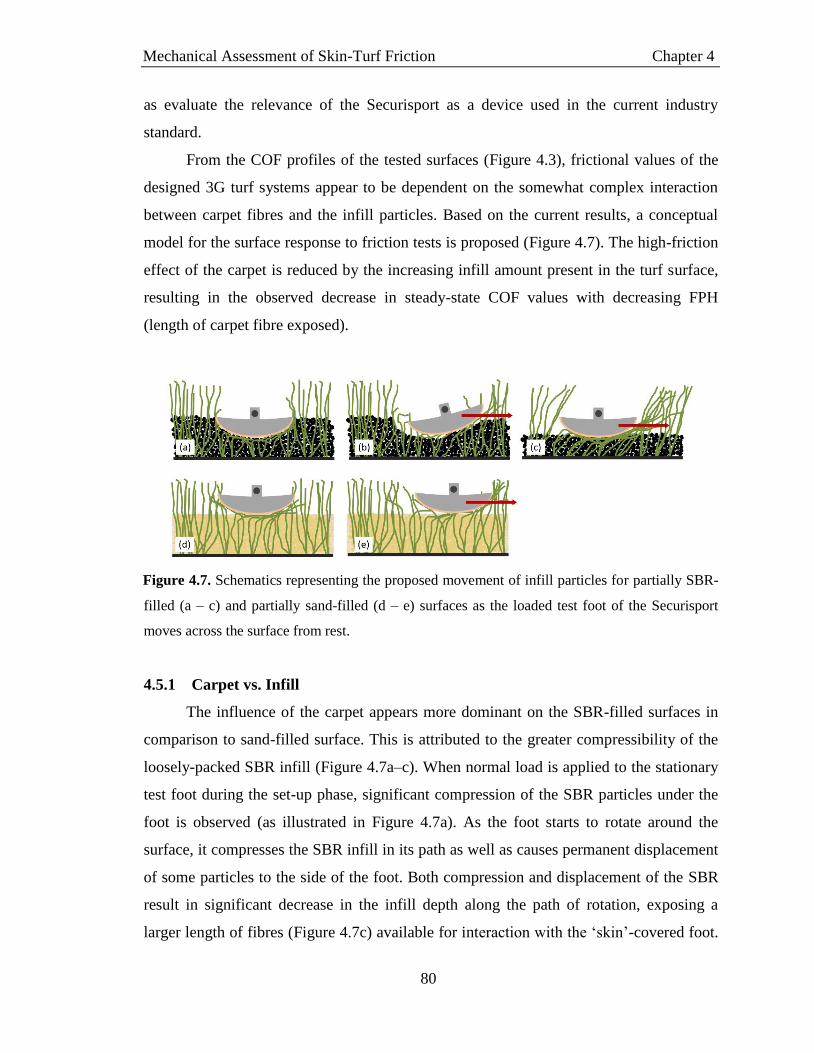
Mechanical Assessment of Skin-Turf Friction Chapter 4
80
as evaluate the relevance of the Securisport as a device used in the current industry
standard.
From the COF profiles of the tested surfaces (Figure 4.3), frictional values of the
designed 3G turf systems appear to be dependent on the somewhat complex interaction
between carpet fibres and the infill particles. Based on the current results, a conceptual
model for the surface response to friction tests is proposed (Figure 4.7). The high-friction
effect of the carpet is reduced by the increasing infill amount present in the turf surface,
resulting in the observed decrease in steady-state COF values with decreasing FPH
(length of carpet fibre exposed).
Figure 4.7. Schematics representing the proposed movement of infill particles for partially SBR-
filled (a – c) and partially sand-filled (d – e) surfaces as the loaded test foot of the Securisport
moves across the surface from rest.
4.5.1 Carpet vs. Infill
The influence of the carpet appears more dominant on the SBR-filled surfaces in
comparison to sand-filled surface. This is attributed to the greater compressibility of the
loosely-packed SBR infill (Figure 4.7a–c). When normal load is applied to the stationary
test foot during the set-up phase, significant compression of the SBR particles under the
foot is observed (as illustrated in Figure 4.7a). As the foot starts to rotate around the
surface, it compresses the SBR infill in its path as well as causes permanent displacement
of some particles to the side of the foot. Both compression and displacement of the SBR
result in significant decrease in the infill depth along the path of rotation, exposing a
larger length of fibres (Figure 4.7c) available for interaction with the ‘skin’-covered foot.

Mechanical Assessment of Skin-Turf Friction Chapter 4
81
The condition of the 3G surface changes continuously for the initial phase of the trial
(first two rotations spanning 3 s) and eventually reaches a relatively consistent state as
represented by the steady-state COF values.
Conversely, the small rigid sand particles are more tightly packed, leading to
reduced bulk-infill movement under the load of the test foot (Figure 4.7d). This results in
a relatively consistent foot-turf interface with lower variation in the FPH during the trial.
It was observed that the COF profiles of the fully-filled surfaces were surprisingly
similar – independent of the carpet or infill type used. The foot-surface interaction may
perhaps be dominated by the mechanism of rolling friction in such cases – where the test
foot moves across the ball-bearing system formed by the infill whereby particles roll over
each other [2, 3]
. Although the fully-filled surfaces displayed a greater change in post-trial
infill depths, the foot-surface interface still largely comprises of interaction with infill
particles where the effect of the minimally exposed turf fibres (Figure 4.1) is insignificant.
When the amount of infill used was reduced and FPH increased (M4, M5, F4 and
F5), the COF profiles appear to be largely influenced by that of the turf fibres as seen
from the pronounced frictional features inherited from the carpet-only surfaces; and an
overall increase in steady-state COF value. This observation implies that the turf fibres
are largely responsible for the friction encountered at the foot-surface interface.
4.5.2 Fibrillated vs. Monofilament Fibres
The fibrillated turf fibres were seen to produce greater frictional values against the
silicone skin samples as compared to the monofilament fibres. This may be attributed to
the fibrillation of the fibre that forms a net-like structure, trapping and hence impeding
mobility of the infill particles, resulting in larger resistance. The fixated infill particles on
the fibres increase the effective surface area of material interacting with the test foot
when subjected to normal loading. Contrary to the fundamental laws of friction, the
interface here involves the interaction of two ‘soft’ elastic surfaces in adhesive contact –
as modelled by the Johnson, Kendall and Roberts (JKR)-Theory. The frictional force
experienced under such rough adhesive contact is also dependent on the surface area,
which increases with normal loading[4]
, as demonstrated in Figure 4.8. With increasing
effective surface area, the frictional force experienced thus deviates from linearity with

Mechanical Assessment of Skin-Turf Friction Chapter 4
82
respect to the normal force, as is the case for sliding friction between two rigid bodies
following Amontons’ Law.
Under the same normal load, the larger interacting area between the test foot and
fibrillated fibres with trapped infill hence results in increased friction. As the trial
proceeds, the moving test foot pushes some of the fibres into the infill, partially
embedding the fibre blades. As a result, the effect of the high-friction turf fibres at the
foot-surface interface reduces and the COF values measured in the third to fifth rotations
oscillate about a lowered frictional value.
Figure 4.8. Schematics of interaction between a) rigid surfaces and b) soft, elastic surfaces.
Amontons’ law describes the interaction between rigid surfaces where the contact area is
independent of the normal load exerted on the system. Whereas the Johnson, Kendall, and
Roberts (JKR)-Theory is used to describe the adhesive contact between elastic bodies where the
effective surface area increases with normal load.
4.5.3 Surface Roughness (Sq)
Part of the FIFA-08 test method involves the determination of the “sliding distance
force” of the silicone ‘skin’ samples – that is, the force required to slide the silicone
‘skin’-attached test foot for a distance of 100 mm across a polished steel plate.[5]
The
sliding distance force of the sample before and after the Securisport trial is used to
quantify the abrasion suffered by the ‘skin’. This assessment of skin abrasion was found
to produce inconsistent and unrepresentative results and hence not included in this study
(Appendix 3). This was because the force measured is highly-dependent on the condition

Mechanical Assessment of Skin-Turf Friction Chapter 4
83
of the stainless steel plate such as its grain orientation and finishing – parameters which
are not specified in the test standard. Furthermore, it is difficult to relate the measurement
of force and the corresponding abrasion calculation (FIFA-08) to the damage caused to
the ‘skin’ as higher skin-steel friction does not translate to higher skin-turf friction. The
approach of direct measurement was selected instead, where the topographies of the ‘skin’
samples were traced using a surface profiler.
The surface analysis of the tested ‘skin’ samples showed reduced surface
roughness (Sq). The observed phenomenon is similar to the smoothing effect via a
‘sanding’-type process [6, 7]
which suggests abrasion and material loss of the initially
rough silicone ‘skin’. Samples tested on the carpet-only and sand-filled surfaces showed
lower Sq values as compared to those tested on SBR-filled surfaces. This phenomenon is
illustrated in Figure 4.9 which shows the schematics representing the movement of
surface infill particles under the loading of the test foot during a trial. When rolling across
the infill surface, the rigid sand particles tend to cut into the soft silicone ‘skin’ as further
packing of the particles into the underlying infill is restricted by the already-compact
surface. This results in the sanding effect of the ‘skin’ samples, ironing out the surface
morphology to result in a smoother ‘skin’. On the other hand, as the SBR particles roll
along between the foot-surface interface, they tend to displace toward the infill surface,
compressing the bulk infill particles. In addition, the softer SBR particles deform
reversibly when interacting with the ‘skin’, resulting in less damage.
For ‘skin’ samples tested on carpet-only surfaces, the increased abrasion may also
be due to the stiffer tufted-ends of the fibres (near the carpet backing) scraping the soft
silicone ‘skin’ – this is especially so for the fibrillated fibres which are twisted and hence
more rigid at the tufted-ends. Adding infill to the carpets eliminates this carpet-base
effect, thereby reducing the abrasiveness or damage done to the ‘skin’.
For partially-filled surfaces with fibrillated carpets (F2 and F3), the low
abrasiveness as reflected by the smaller Sq changes can be attributed to the thinner fibre
thickness (0.1 mm) as compared to the monofilament fibres (thickness = 0.3 mm). As the
test foot traverses the surface, the initial net-like structure of the fibrillated fibre gives
way and splits into smaller fibre strands. These individual fibre strands of lower
resiliency are subsequently less abrasive as compared to the monofilament fibres,

Mechanical Assessment of Skin-Turf Friction Chapter 4
84
inflicting less damage on the silicone skin. For both carpets, further increase of infill
levels would lead to the transition to the sanding-effect of infill particles on the ‘skin’
samples as described earlier.
Figure 4.9. Schematics showing the rolling friction of infill particles (highlighted in blue) at the
foot-surface interface for (a) sand-filled and (b) SBR-filled surfaces. The turf fibres were
removed for easy illustration of infill movement. Black arrows represent the tendency of surface
infill particles to compress into the ‘skin’ sample whereas red arrows represent the tendency of
the particles displacing towards the bulk infill mass.
4.5.4 Evaluation of the FIFA-08 Test Method
The FIFA-08 is the current industry standard for the assessment of skin friction
and skin abrasion of artificial turf surfaces. In this study, the Securisport test device was
used in accordance with the published test method, using the (standard) silicone ‘skin’
substitute. The results showed that with varying carpet-infill combinations, a range of
frictional behaviours were achieved as recorded by the COF-time profiles from the
Securisport device. Additional characterization of the ‘skin’ roughness pre- and post-
Securisport testing suggests that ‘skin’ is damaged to various extents during the trial
rotations via interactions with the respective surfaces. This implies that the surface
roughness of the ‘skin’ samples changes continuously throughout each trial, depending
on the ‘abrasiveness’ of the 3G surfaces. The inconclusive skin abrasion measurements as

Mechanical Assessment of Skin-Turf Friction Chapter 4
85
per the FIFA-08 test method as presented in Appendix 3 and by Lenehan and Twomey,
further suggests that a direct measure of the ‘skin’ roughness for the determination of
extent of damage, is warranted.
When comparing the skin-friction of different artificial turf surfaces, the frictional
behaviour of the prepared 3G surfaces should be assessed using ‘skin’ samples with
consistent surface properties. However, the current results suggest that this is not the case
for tests carried out following the FIFA-08 methodology. Due to the surface-dependent
‘skin’ damage, it is difficult to compare the COF profiles and essentially the average
COF values (FIFA-08) of the different 3G surfaces as at any one point in time during the
trial, the state of the ‘skin’ samples used varies from surface to surface. This constrains
the scope of the study to using the Securisport only as a tool for identifying the turf
component which is the major contributor to the overall ‘skin’-turf friction, while
systematic investigation into specific friction or abrasion mechanisms is limited.
Previous studies to develop test devices have also critiqued the Securisport device
in terms of its non-biofidelity to human movement during a game.[8, 9]
The 100 N normal
load (mass of 10.2 kg) used in the standard FIFA-08 test has been argued to be far from
the average weight of professional players (71.8 - 82.5 kg; 704.6 – 809.3 N)[10, 11]
, while
the rotational movement of the Securisport test foot does not replicate the seemingly
linear sliding motion. The speed at which the test foot traverses the turf surface (40 rpm =
0.838 m/s) is also slower than the average running speed of a player in a game (3.3 – 6.7
m/s).[8, 12]
In addition, the L7350 silicone skin used in the assessment may not provide the
best simulation of real skin properties which consists of multiple layers of tissue with the
complex integration of features such as hairs, glands, nerves and vessels.
The current lack of literature describing the biomechanics of the sliding motion
poses a limitation to the design of better testing devices, though certain arguments can be
made to justify the simple design of the Securisport testing device. The constraints of
portability and space limit the loads and motions applicable for a lab-based equipment.
Furthermore, assuming that other parts of the player’s body are in contact with the turf
during the execution of a sliding tackle, weight distribution across all contact points
reduces the net normal load exerted onto the area of skin subjected to abrasion. Only
when future work enables the availability of these biomechanics parameters, then can

Mechanical Assessment of Skin-Turf Friction Chapter 4
86
biofidelic test equipment be developed, such as in the case of robot simulation. Despite
the current lack of knowledge, the outcomes of this study can provide some
recommendations for the future direction of mechanical assessment of skin-surface
behaviour of artificial turfs.
Working within the current constraints of mechanical testing devices,
modifications can be made to material selection or equipment design to quantify and
compare the frictional behaviour of turf surfaces. A more robust material with higher
wear-resistance can be selected to replace the soft silicone ‘skin’ to ensure consistent
roughness conditions throughout the test trial. However, subsequent correlations of such
material-turf friction to skin-turf friction will be necessary to effectively evaluate the skin
friction properties of artificial turfs. Further work can be done to analyse the surface
roughness of ‘skin’ subjected to various degrees of abrasion by obtaining samples from
trials of different number of rotations. For the current set-up, assuming that the major
surface-dependent changes in the ‘skin’ occurred during the initial two rotations – where
the COF peaked for all surfaces – a compromise may be to alter the operation of the
Securisport to provide more consistent and realistic movement profile. A possible design
modification would be to monitor the frictional values as the moving test foot is lowered
onto the turf surface and brought to a stop. This motion better represents the deceleration
of a player as he/she slides on the turf surface, improving the biofidelicity of the
equipment.
For the assessment of skin abrasion determined by the damage inflicted onto the
‘skin’ sample, a direct measurement of surface roughness is likely to be more reliable
than the indirect method currently employed (FIFA-08). Additionally, the monitoring of
the changes in ‘skin’ roughness with testing duration may reveal insights to the damage
mechanism involved in skin-surface interactions – providing information on the abrasion
threshold of skin information which may be beneficial for injury preventions.
4.6 Conclusion
The effect of artificial turf components on the overall turf frictional behaviour was
investigated using the standard FIFA mechanical test device – the Securisport Sport
Surface Tester. From the results, the carpet fibres were identified as the major contributor

Mechanical Assessment of Skin-Turf Friction Chapter 4
87
to the overall friction and abrasion of the surface. This was more pronounced for styrene
butadiene rubber (SBR)-filled surface where the large movement and compressibility of
the SBR particles resulted in longer pile lengths exposed, enhancing fibre-interaction
with the test foot. Fibrillated fibres showed higher skin-surface frictional values which
can be attributed to their net-like structure immobilizing infill particles hence, producing
more resistance to the movement of the test foot. This study also demonstrated that the
direct measurement of ‘skin’ roughness pre- and post-Securisport testing may provide an
acceptable means of assessing skin damage for a given turf surface. Notably, this damage
should be accounted for when analysing frictional properties of the surface as the varying
extents of ‘skin’ damage complicate the direct comparison of friction between surfaces.
Overall, the reported differences in frictional values and abrasiveness of the
sampled turf systems appear to be largely influenced by the carpet properties and may
provide immediate implications on the selection of skin-friendly turf products from the
wide array of available carpets. As one of the first attempts to evaluate the Securisport
device and the FIFA-08 test method, this study questions the validity of the industry
standard as a means to measure and compare the frictional behaviour of different
artificial turf surfaces – primarily due to the changing roughness state of the ‘skin’ model
throughout the test. Working within the limitations of the device and test method, the
current results can provide useful data to aid in the further development of mechanical
assessment of ‘skin’ surface frictional behaviour of artificial turfs.
4.7 References
[1] K.A. Lenehan and D.M. Twomey, Abrasion testing on synthetic turf: A modified
device. Proc. Inst. Mech. Eng. Part P J. Sport. Eng. Technol. 2015.
[2] A. Fall, B. Weber, M. Pakpour, N. Lenoir, N. Shahidzadeh, J. Fiscina, C. Wagner,
and D. Bonn, Sliding friction on wet and dry sand. Phys. Rev. Lett. 2014, 112, 3–6.
[3] O. Tevet, P. Von-Huth, R. Popovitz-Biro, R. Rosentsveig, H.D. Wagner, and R.
Tenne, Friction mechanism of individual multilayered nanoparticles. Proc. Natl. Acad.
Sci. 2011, 108, 19901–19906.
[4] V.L. Popov, Contact Mechanics and Friction, 1st ed., Springer-Verlag Berlin
Heidelberg, 2010.
Mechanical Assessment of Skin-Turf Friction Chapter 4
88
[5] Fédération Internationale de Football Association (FIFA), FIFA Quality Concept
for Football Turf - Handbook of Test Methods, 2012.
[6] P.D. Evans and I. Cullis, Effect of sanding and coating with UV-cured finishes on
the surface roughness, dimensional stability and fire resistance of oriented strandboard.
Holz Als Roh- Und Werkst. 2008, 66, 191–199.
[7] G. Nemli, T. Akbulut, and E. Zekoviç, Effects of some sanding factors on the
surface roughness of particleboard. Silva Fenn. 2007, 41, 373–378.
[8] C. Ingham, Linear vs . Rotational Skin Friction, 2013.
[9] R. Verhelst, S. Rambour, P. Verleysen, and J. Degrieck, Temperature
development during sliding on different types of artificial turf for hockey, in:
International Conference on Latest Advances in High-Tech Textiles and Textile-Based
Materials, 2009, pp. 90–95.
[10] A. Junge, J. Dvorak, J. Chomiak, L. Peterson, and T. Graf-Baumann, Medical
history and physical findings in football players of different ages and skill levels. Am. J.
Sports Med. 2000, 28, S16–S21.
[11] M. Peppelman, W.A. van den Eijnde, A.M. Langewouters, M.O. Weghuis, and
P.E. van Erp, The potential of the skin as a readout system to test artificial turf systems:
clinical and immunohistological effects of a sliding on natural grass and artificial turf. Int.
J. Sports Med. 2013, 34, 783–788.
[12] H. Andersson, B. Ekblom, and P. Krustrup, Elite football on artificial turf versus
natural grass: movement patterns, technical standards, and player impressions. J. Sports
Sci. 2008, 26, 113–122.

Surface Modification for Skin-Friendly Surfaces Chapter 5
89
Chapter 5
Surface Modification for Skin-Friendly Surfaces
This chapter presents the effect of surface modification using
polyzwitterionic brushes as a potential strategy to create skin-friendly
surfaces. Results from materials preparation and characterization show the
successful surface grafting of the poly(sulfobetaine methacrylate) brushes
onto the polypropylene substrates. Frictional measurements were designed
to simulate the conditions of artificial turf surfaces while using skin models
so as to provide relevant assessments of the skin-friendliness of the prepared
samples.

Surface Modification for Skin-Friendly Surfaces Chapter 5
90
5.1 Introduction
The focus of this research project was to improve the skin-friendliness of artificial
turf surfaces by first identifying the key friction-contributing component and
subsequently addressing the abrasive issue via material modification. This chapter
presents the results of the materials engineering work, where the bulk material of
identified turf fibres component (Chapter 4) was functionalized with zwitterionic polymer
sulfobetaine methacrylate (pSBMA) brushes using the method of photoinduced surface
grafting.
The work in this chapter has been divided into two parts; material functionalization
using pSBMA, and the skin-friendliness study of the modified substrates through
improved frictional behaviour and antifouling properties. The identified polypropylene
(PP) substrates were grafted with pSBMA under conditions of varying monomer
concentrations, initiator concentrations and photoirradiation durations, thereafter, the
optimized conditions were selected and used to produce modified-PP samples which
were further characterized.
The tribological study was designed as a bench-top test, assessed with FIFA-
approved L7350 silicone ‘skin’, which can potentially be used as a standard test set-up
for repeatable skin-friction analysis of turf fibres during the manufacturing process.
Bioassay using Staphylococcus aureus (S. aureus) assay was used to determine the
antifouling properties of the modified samples. Overall, the effectiveness of the pSBMA
modification on improving skin-friendliness of the substrates are summarized and
discussed, offering a feasible scalable solution to the addressing of abrasive artificial turf
surfaces.
5.2 Photoinduced Grafting of pSBMA
5.2.1 Gravimetric Analysis
The grafting densities of the PP substrates were used to select the experimental
conditions for preparation of subsequent pSBMA-functionalized samples. The
quantification of grafting was determined gravimetrically where the mass gain from the
pSMBA-grafting per unit substrate area is presented in Figure 5.1. The data sets are
presented for comparison of the effect of photoinitiator (BP) concentration for fixed

Surface Modification for Skin-Friendly Surfaces Chapter 5
91
monomer (SBMA) concentrations (Figure 5.1a) and the effect of monomer
concentrations for fixed photoinitiator concentrations (Figure 5.1b).
For all BP-SBMA combinations, it was observed that the mass gain per unit area
of the samples increases with UV irradiation time, indicating that a larger amount of
pSBMA brushes are grafted as the reaction is allowed for a longer duration. The grafting
density also increases with both the concentrations of the photoinitiator and monomer
with the benzophenone concentration of 10 wt% coupled with SBMA concentration of
0.2 M producing samples with the highest grafting densities.
The highest achieved grafting density of 0.284 ± 0.018 mg/cm2 of pSBMA (after
1200 s of irradiation) is comparable to the 0.4 mg/cm2 obtained by Chiang et al. via
surface-initiated atom transfer radical polymerization (SI-ATRP) onto poly(vinylidene
fluoride) (PVDF) membranes for a reaction period of 24 h.[1]
As reviewed in Chapter 2,
SI-ATRP is the preferred graft-from method for the preparation of surface-grafted
polymer brushes due to the high controllability of molecular weight distribution and high
grafting density. However, the feasibility and economics of applying SI-ATRP to large-
scale manufacturing lines are unfavourable – factors that are key considerations in the
development of modification methodology for this project. It is therefore encouraging
that the grafting results achieved via UV-induced free radical polymerization are in a
comparable range to that obtained by SI-ATRP.
The respective concentrations of 10 wt% and 0.2 M for BP and SBMA were thus
selected for preparation of the modified PP substrates for subsequent testing. This was to
ensure sufficiently dense grafting of the pSBMA brushes for effective functionalization
of the substrates that exhibit characteristic properties of the zwitterionic surface layer.[2]
Irradiation duration is retained as a variable to demonstrate the effect of grafting extent
on the effectiveness of the surface modification.

Surface Modification for Skin-Friendly Surfaces Chapter 5
92
Figure 5.1. Grafting density of the pSBMA-grafted samples summarized according to (a) varying
monomer concentration and (b) varying photoinitiator concentration.
5.2.2 Material Characterization
The effect of surface modification was first characterized via contact angle
measurement – to determine the extent of hydrophilicity introduced by the grafting of

Surface Modification for Skin-Friendly Surfaces Chapter 5
93
zwitterionic SBMA polymer brushes. Figure 5.2 shows the decrease in water contact
angle with irradiation duration of the samples from 90.3 ± 3.0° (PP substrate) to 15.4 ±
1.9° (1200 s), illustrating the increased presence of the hydrophilic brushes that
significantly improved the water affinity of the hydrophobic PP substrate. The change in
contact angle also gives an indication of the surface coverage by the grafted polymer
brushes – with increasing modification of the surface with reaction times. This was
further validated by FESEM imaging (Figure 5.3) where it can be observed that an
increased number of polymer brushes (of increasing dimensions) were grafted onto the
PP substrate and complete surface coverage was achieved after 1200 s of irradiation.
Figure 5.3v shows the grafted polymer brushes existing as globules on the sample surface,
with an average diameter of approximately 200 nm. The hydrophilic pSBMA brushes
coil up to assume globular structures under dry conditions as a result of the strong
interactions between intra-chain zwitterionic functional groups prevailing that with the
less favourable surroundings.[3–5]
The larger globules observed for longer irradiations
suggest increased polymer brush lengths.

Surface Modification for Skin-Friendly Surfaces Chapter 5
94
Figure 5.2. Water contact angle measured on the pSBMA-grafted PP samples with increasing
irradiation durations of 0 s to 1200 s. Insets show representative images of the contact angle
measurements for each sample.

Surface Modification for Skin-Friendly Surfaces Chapter 5
95
Figure 5.3. FESEM images of the pSBMA-grafted samples with increasing irradiation durations
of 0 s to 1200 s (i – v) at magnifications of 10000x and 30000x (insets).
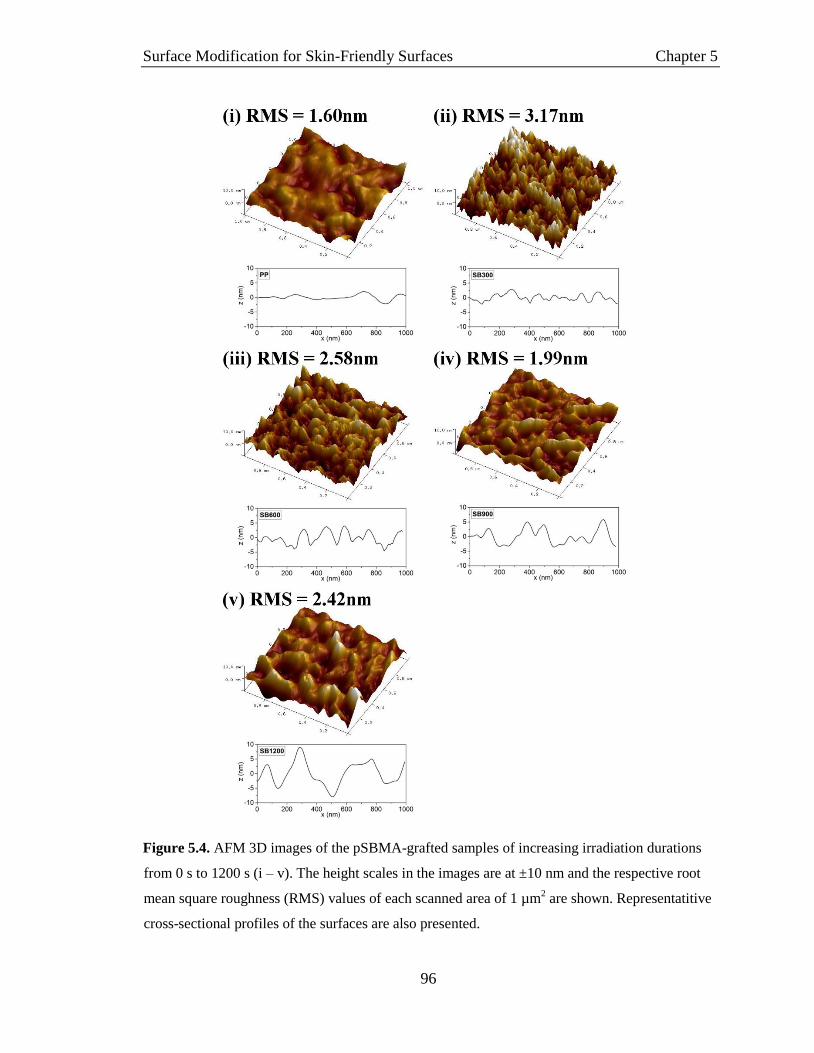
Surface Modification for Skin-Friendly Surfaces Chapter 5
96
Figure 5.4. AFM 3D images of the pSBMA-grafted samples of increasing irradiation durations
from 0 s to 1200 s (i – v). The height scales in the images are at ±10 nm and the respective root
mean square roughness (RMS) values of each scanned area of 1 µm2 are shown. Representatitive
cross-sectional profiles of the surfaces are also presented.

Surface Modification for Skin-Friendly Surfaces Chapter 5
97
AFM imaging of the dried sample surfaces also show the increasing polymer
brushes globule sizes with UV-exposure duration (Figure 5.4). The RMS surface
roughness increases from 1.60 nm for the pristine PP substrate to 3.17 nm and 2.58 nm
for samples irradiated for 300 and 600 s respectively, followed by a slight decrease to
1.99 nm and 2.42 nm for the 900 s and 1200 s samples. The initial increase in surface
roughness can be attributed to the formation of tiny polymer brush globules on the
substrate surface. With subsequent growth in polymer brush length, the globule sizes
increase and RMS roughness decreases. Globule sizes from AFM measurements
correspond with that from the FESEM images, showing dimensions of approximately 200
nm for brushes grown for 1200 s, while cross-sectional profiles show that the pSBMA
globules are of approximately 17 nm in height under dry conditions Figure 5.4v.
The chemical identity of the grafted samples are determined by FTIR-ATR and the
respective spectra are shown in Figure 5.5. It can be seen from the spectra that
characteristic peaks at 751 cm-1 (CS), 1043 cm-1 (SO) and 1722 cm-1 (COO) appeared
and increased in intensity for samples irradiated for longer durations, implying the
increased presence of pSBMA on the sample surface.[1]
The inset figure presents the
semi-quantitative analysis of the relative intensity of SO peaks against reference CH
(1457 cm-1) stretching peaks in each sample spectrum. As aliphatic PP was used as the
substrate, the presence of CH peaks were assumed to be from the substrate, with
negligible contribution from the grafted polymer brushes. It was observed that the
presence of SO peaks increased with irradiation duration, indicating higher grafting
extents with longer UV-exposure times. In addition, a large OH stretching band at 3445
cm-1 appeared with increased surface grafting of pSBMA which indicates the presence of
surface hydration. This further affirms the successful surface grafting and can be
attributed to the hydroscopic nature of the zwitterion – absorbing trace amounts of
atmospheric water as the FTIR-ATR analysis was carried out in ambient conditions.[3, 6]

Surface Modification for Skin-Friendly Surfaces Chapter 5
98
Figure 5.5. FTIR-ATR transmittance spectra of pSBMA-g-PP samples comparing the (i) pristine
PP substrates with samples irradiated for (ii) 300 s, (iii) 600 s, (iv) 900 s and (v) 1200s. The inset
shows the relative intensity of the characteristic SO peaks (at 1043 cm-1) to the reference CH
peaks (at 1457 cm-1) for each sample
The chemical compositions of the modified samples were further ascertained by
XPS analysis (Figure 5.6). Si 2s and Si 2p peaks in the spectra were omitted from the
analysis as they originated from the underlying glass slides on which the samples were
secured. The glass-contamination also contributes to bulk of the O 1s peak detections,
evident from the detection of the O 1s peak in the survey spectra of the PP substrate. In
the spectrum of the prepared pSBMA-g-PP samples, the emission peaks at 168.0 eV (S
2p) and 402.9 eV (N 1s) confirmed the polymerization of pSBMA brushes. Detailed
information about the chemical functionalities of the detected elements were obtained
from the high resolution region scans where the measured peaks were deconvoluted to
identify the various chemical states of the elements.
For the PP substrate, the C 1s core-level spectrum shows a single peak at 285.0 eV
corresponding to the C-C group while O 1s core-level spectrum shows a single fitted
peak at 532.6 eV which corresponds to the O–Si group, validating that the detected

Surface Modification for Skin-Friendly Surfaces Chapter 5
99
oxygen is from contamination by the glass slide used. All pSBMA-grafted samples
displayed similar high-resolution spectra, with varying intensities for the N 1s and S 2p
peaks. The C 1s core-level spectrum shows 4 peaks at 289.3, 286.9, 285.8 and 285.0 eV,
corresponding to the groups of O–C=O, C–O, C–N and C–C respectively. With
increasing irradiation duration, the intensity of the O–C=O, C–O and C–N peaks
increased. Similarly, the result of successful grafting of pSBMA manifests in the
detection of O*–C=O and SO3- peaks at 534.1, 532.6 and 531.6 eV in the O 1s core-level
spectrum; and R4N+ (where R represents general hydrocarbon groups) and N–C peaks at
402.9 and 400.2 eV in the corresponding N 1s spectrum.
From Figure 5.6vi, the concentration of N 1s and S 2p detected on each of the
sample surfaces appears to be in a 1:1 ratio, confirming the chemical identity of the
grafted brushes as pSBMA. Overall, the XPS results show successful grafting of the
pSBMA brushes onto the PP substrate, with the extent of grafting increasing with
irradiation duration.

Surface Modification for Skin-Friendly Surfaces Chapter 5
100
Figure 5.6. XPS results of (i) the PP substrate and grafted samples irradiated for (ii) 300 s, (iii)
600 s, (iv) 900 s and (v) 1200 s. Each sub-figure shows the XPS spectra of the survey scan with
characteristic elemental peaks identified by arrows; together with the corresponding region scans
and analysis to determine the respective chemical states of the elements. The detected N 1s and S
2p concentrations on each sample are summarized in (vi).
5.2.3 Characterization of Surface Water
Having successfully grafted pSBMA brushes onto the PP substrates via UV-
induced surface grafting, analysis using DSC was carried out to determine the state of
water adsorbed onto the modified substrates. The endothermic melting peaks detected in
the DSC thermograms (Figure 5.7) were attributed to the amount of freezable (i.e. bulk)

Surface Modification for Skin-Friendly Surfaces Chapter 5
101
water adsorbed onto the sample surfaces during the hydration process – water molecules
that are not bound by hydrogen bonding to the sample.[7, 8]
Only the temperature range of
-20 to +20 °C was presented as no other thermal transitions were observed outside this
temperature range on the heating curve. As anticipated, the area of the endothermic
transitions decrease with irradiation durations. With less pSBMA brushes grafted onto the
substrate surface, the decreased hydrophilicity of the samples result in a smaller amount
of water being attracted and bonded to the surface, as illustrated by the DSC results.
The states of water associated with hydrophilic polymers are often categorized as
free water, freeze-bound water and non-freezable bound water. Free water is analogous to
the bulk water quantified using DSC while freeze-bound water is often represented by a
secondary endothermic peak occurring at sub-0°C temperatures. On the other hand, non-
freezable bound water does not crystallize even at temperatures as low as –100°C.[9]
Both
freeze-bound and non-freezable bound water are a result of strong interactions between
water molecules and the polar functional groups of the hydrophilic polymer.
From the DSC results, freeze-bound water is absent while the amount of non-
freezable bound water determined gravimetrically increased with irradiation duration
(inset of Figure 5.7) from 0% (PP substrate) to 15.6% (1200 s). This observation is in line
with the studies by Ishihara[10]
and Kitano[11]
where water adsorbed onto zwitterionic
polymers (in general phosphorylcholines and sulfobetaines) behaves differently from that
on other amphiphilic polymers (e.g. poly[2-hydroxythyl methacrylate (pHEMA)]). It was
found that water adsorbed onto zwitterionic polymers exist as either free water or non-
freezable bound water. The lack of water exhibiting freeze-bound behaviour explains the
well-known excellent biocompatibility and antifouling properties of zwitterionic
polymers – providing a strongly bounded yet uninterrupted bulk-water-like surface for
bioorganic entities to contact reversibly, without changing their conformations.[10, 11]

Surface Modification for Skin-Friendly Surfaces Chapter 5
102
Figure 5.7. DSC thermogram of the hydrated samples showing the endothermic freezing peaks of
absorbed water on the respective pSBMA-grafted samples. The inset shows the amount of non-
freezable water as a percentage of the total water absorbed.
5.2.4 Frictional Assessment using L7350 Silicone Skin
The scope of this project relates surface abrasiveness to its frictional interaction
with skin where excessive friction may lead to damage of the epidermis.[12–15]
In addition
to discomfort and bleeding, the abrasion wounds act as points of entry for bacterial
infection[16]
, potentially leading to further complications.
The frictional properties of the modified samples were hence studied, to
understand the effect of pSBMA grafting on improving skin-sample friction. The
frictional studies were designed as a bench-top test instead of in vivo testing using live
subjects due to ethical considerations and the inconsistency of tribological results on
human skin.[17–21]
FIFA-approved L7350 silicone skin was used as the standard testing
material as it is currently used by the football governing body for the testing of skin
abrasiveness of large-scale artificial turf systems. Furthermore, silicone has the highest

Surface Modification for Skin-Friendly Surfaces Chapter 5
103
replication of human skin properties amongst commonly available materials[22]
and is
used for the manufacturing of skin surrogates.
The frictional assessments were conducted with the pSBMA-modified samples
being in both dry and hydrated states – to simulate conditions that the products may be
subjected to when installed and used in an artificial turf surface. When tested dry, all
samples exhibited high frictional values in the range of 0.98 – 1.24 (unfilled columns in
Figure 5.8). Although the frictional values are not correlated to actual human skin-turf
interaction, coefficients of friction exceeding unity (µ > 1) imply large resistance against
motion, where excess energy is required to overcome the friction in order for the object to
stay in motion. This is resonated in the abrasion injuries suffered on artificial turf
surfaces where the epidermis is sacrificed when subjected to high friction.
Under dry conditions, the frictional mechanism of interlocking asperities
dominates – with an observable increase in µ values measured for samples with high
grafting extents. As verified from the FESEM and AFM characterizations, pSBMA
brushes adopt globular structures in their dry states. The globule sizes increase with
irradiation duration due to the longer chain lengths and this results in the formation of
large asperities that causes increased friction when moved against the surface roughness
of silicone tribo-tips.[23, 24]

Surface Modification for Skin-Friendly Surfaces Chapter 5
104
Figure 5.8. a) Coefficient of friction (µ) values of dry and hydrated pSBMA-grafted samples of
varying irradiation durations measured using a L7350 silicone skin tribo-tip, in an ambient
environment. b) and c) are schematics illustrating the configuration of the grafted-pSBMA
brushes when under dry and hydrated conditions respectively.
In the presence of hydration, the coefficients of friction remain largely unchanged
for the hydrophobic PP substrate and for the sample subjected to the lowest amount of
surface modification (irradiation duration = 300 s). This observation is in line with that of
Bongaerts et al., where the coefficients of friction for hydrophobic-hydrophobic
poly(dimethylsiloxane) (PDMS) tribo-pairs are similar (and consistently high; µ > 1)
under both dry and hydrated conditions.[25]
When the hydrated PP-L7350 tribo-pair is

Surface Modification for Skin-Friendly Surfaces Chapter 5
105
subjected to normal loading, most of the water at the interface is expelled as neither of
the hydrophobic surfaces are capable of holding on to the hydration.
On the other hand, significant decrease in frictional values was observed for
samples that were extensively grafted with pSBMA brushes (irradiation duration ≥ 600 s).
The lowest coefficient of friction was measured on the pSBMA-grafted samples
irradiated for 900 s, with a µ value of 0.30 ± 0.07 while the greatest decrease in friction
due to hydration (75.8% decrease as compared to µ measured under dry conditions) was
registered on the sample irradiated for 600 s. The low frictional values can be attributed
to the pSBMA-modification which allowed for water to be bounded to the hydrophilic
polymer brushes, resulting in the formation of a hydration layer. This tightly-bounded,
non-compressible layer of water separates the asperities on the interacting surfaces,
acting as lubrication to reduce friction caused by deformation and ploughing.[26–28]
In comparison with other frictional experiments involving zwitterioinc polymers,
the absolute µ values for the hydrated pSBMA-modified surfaces obtained in this study
are high. As reviewed in Chapter 2, µ values of as low as 0.018[29]
, 0.025[30]
and
0.000043[31]
have been achieved. However, these studies have been carried out in a
submerged environment where there is an abundance of water molecules surrounding the
polymer brushes, equivalent to a continuous supply of lubricant during the frictional
measurement; unlike the ambient conditions used in this study which simulates the actual
environment the material will be applied in and hence limits the amount of lubricating
water available. Secondly, the higher µ values can also be explained by the significantly
larger contact area between the L7350–sample tribo-pair. Assuming the Johnson-Kendal-
Roberts model of contact mechanics for adhesive elastic contacts[23]
, the contact area for
the L7350-sample interaction subjected to a 0.2 N load is approximated to be ~3 mm2,
significantly smaller than typical tribological studies using apparatuses such as the AFM
with micron-scale colloidal probes (7×10⁻⁵
mm2)[32]
; or the Surface Force Balance (SFB)
under very small normal loads (~10-3
N).[31]
Lastly, the set-up in this study measures the
friction between a polymer brush-grafted surface and a non-modified tribo-tip – which
inherently will produce higher frictional values than studies involving the interaction
between hydrated polymer brushes tethered from both tribo-tip and sample surface.[29, 31,
33, 34]

Surface Modification for Skin-Friendly Surfaces Chapter 5
106
The reduction in frictional value achieved in this study is significant when
compared to the ~40% decrease in µ achieved by Kobayashi et al. for grafted pMPC
brushes in dry and aqueous environments tested against a glass probe of similar
dimensions.[34]
These results show that the photo-induced grafting of pSBMA-brushes on
PP is promising for the development of skin-friendly artificial turfs – validated by an
appropriate testing method with a suitable counter-surface which simulates skin-turf
interaction under ambient conditions.
5.2.5 Resistance towards Fouling by S. aureus
In addition to reduced friction against the L7350 skin substitute, the skin-
friendliness of the modified samples are also determined by their resistance towards the
surface adhesion by infection-causing pathogens. The prepared pSBMA-grafted samples
were assayed against the bacterium strain S. aureus – due to its well-documented risk
associated with skin infections[35, 36]
and the prevalence of S. aureus incidents within the
sporting community.[37–39]
The bioassay results show that antifouling properties improved with surface
grafting of pSBMA brushes as can be seen from the decreased surface coverage of the
cell colonies on the surfaces with increasing irradiation duration (Figure 5.9). The
antifouling properties improved dramatically, achieving negligible bacteria fouling (0.09%
cell-surface coverage) for samples irradiated for 900 s and longer; compared to the 33.4%
surface coverage on the PP substrate control.
The antifouling property of pSBMA is commonly attributed to the capability of
zwitterionic moieties to tightly bound non-freezable water molecules, as verified in the
DSC results in Section 5.2.3. The water molecules bounded via strong electrostatic
attractions to the charged groups on the polymer brushes form a barrier that prevents cell
and protein access to the hydrophobic PP substrate. In order for the cells to contact and
subsequently colonize the sample surfaces, they will first have to expel the obstructing
water molecules in the tightly-held hydrated layer – an energetically unfavourable
process for the cells.[40, 41]
In addition, the absence of freezable-bound water allows the
bacteria cells to approach and distance the sample surface; exchanging like-water
molecules with the hydrated layer without perturbing cell-wall proteins (schematic in

Surface Modification for Skin-Friendly Surfaces Chapter 5
107
Figure 5.10), preserving their conformations as if they were moving in bulk water.[3, 10, 11]
The tethered pSBMA brushes hence make the PP substrate appear “invisible” to the
bacteria cells, largely reducing the tendency for cell adsorption and colonization on the
sample surfaces.
Figure 5.9. FESEM images of S. aureus bacterial cells adsorbed onto the pSBMA-grafted PP
samples of increasing irradiation durations from 0 s to 1200 s (i – v) (scale bars represent 50 µm).
The insets show corresponding bacterial colonies on each sample imaged at 5000x magnification.
The results of image analysis of the area coverage by the S. aureus cells is summarized in (vi).

Surface Modification for Skin-Friendly Surfaces Chapter 5
108
Figure 5.10. Schematics describing the antifouling mechanism by hydrated pSBMA brushes.
5.3 Conclusion
The strategy of photo-induced surface grafting of pSBMA brushes was employed
with the objective of improving skin-friendliness of the PP substrate – a common bulk
material used in the manufacturing of artificial turf fibres. Successful grafting was carried
out and the tethered zwitterionic brushes were analysed by material characterization
methods – where longer and denser brushes were observed with increased sample-
irradiation durations. The modified surfaces were also rendered hydrophilic, with an
increasing content of surface-adsorbed water being made up of non-freezable water. The
presence of such strongly-bounded water molecules resulted in the superior lubricating
effect of the hydrated samples that effectively reduced ‘skin’-surface friction. The bench-
top tribological study, specially designed to simulate the eventual application
environment, showed that hydrated pSBMA brushes are capable of reducing frictional
values of up to 78.8% even in the absence of excess water. Bioassays of the pSBMA-
grafted samples showed effective antifouling properties against pathogenic S. aureus
cells, with near zero surface adsorption/colonization.
In conclusion, surface grafting of pSBMA brushes onto artificial turf fibers may be
a highly feasible strategy to improve skin-friendliness of the product due to the improved
frictional and antifouling properties – addressing the issue of skin abrasion and infection
from playing on artificial turf fields. The process of photo-initiated surface grafting can

Surface Modification for Skin-Friendly Surfaces Chapter 5
109
also be scaled up and easily integrated into the continuous process for the manufacturing
of yarns and eventually artificial turf fibres.
5.4 References
[1] Y.C. Chiang, Y. Chang, A. Higuchi, W.Y. Chen, and R.C. Ruaan, Sulfobetaine-
grafted poly(vinylidene fluoride) ultrafiltration membranes exhibit excellent antifouling
property. J. Memb. Sci. 2009, 339, 151–159.
[2] Y. Zhang, Z. Wang, W. Lin, H. Sun, L. Wu, and S. Chen, A facile method for
polyamide membrane modification by poly(sulfobetaine methacrylate) to improve
fouling resistance. J. Memb. Sci. 2013, 446, 164–170.
[3] Y.-H. Zhao, K.-H. Wee, and R. Bai, Highly hydrophilic and low-protein-fouling
polypropylene membrane prepared by surface modification with sulfobetaine-based
zwitterionic polymer through a combined surface polymerization method. J. Memb. Sci.
2010, 362, 326–333.
[4] J. Deng, L. Wang, L. Liu, and W. Yang, Developments and new applications of
UV-induced surface graft polymerizations. Prog. Polym. Sci. 2009, 156–193.
[5] K. Kato, E. Uchida, E.T. Kang, Y. Uyama, and Y. Ikada, Polymer surface with
graft chains. Prog. Polym. Sci. 2003, 28, 209–259.
[6] H. Kitano, K. Nagaoka, S. Tada, M. Gemmei-Ide, and M. Tanaka, Structure of
water incorporated in amphoteric polymer thin films as revealed by FT-IR spectroscopy.
Macromol. Biosci. 2008, 8, 77–85.
[7] F.M. Plieva, M. Karlsson, M.-R. Aguilar, D. Gomez, S. Mikhalovsky, and I.Y.
Galaev’, Pore structure in supermacroporous polyacrylamide based cryogels. Soft Matter
2005, 1, 303–309.
[8] Z. Megeed, J. Cappello, and H. Ghandehari, Thermal Analysis of Water in
Silk−Elastinlike Hydrogels by Differential Scanning Calorimetry. Biomacromolecules
2004, 5, 793–797.
[9] Z.H. Ping, Q.T. Nguyen, S.M. Chen, J.Q. Zhou, and Y.D. Ding, States of water in
different hydrophilic polymers - DSC and FTIR studies. Polymer (Guildf). 2001, 42,
8461–8467.
[10] K. Ishihara, H. Nomura, T. Mihara, K. Kurita, Y. Iwasaki, and N. Nakabayashi,

Surface Modification for Skin-Friendly Surfaces Chapter 5
110
Why do phospholipid polymers reduce protein adsorption? J. Biomed. Mater. Res. 1998,
39, 323–330.
[11] H. Kitano, T. Mori, Y. Takeuchi, S. Tada, M. Gemmei-Ide, Y. Yokoyama, and M.
Tanaka, Structure of water incorporated in sulfobetaine polymer films as studied by
ATR-FTIR. Macromol. Biosci. 2005, 5, 314–321.
[12] W.F. Bergfeld and J.S. Taylor, Trauma, sports, and the skin. Am. J. Ind. Med.
1985, 8, 403–413.
[13] G. Eiland and D. Ridley, Dermatological Problems in the Athlete. J. Orthop.
Sport. Phys. Ther. 1996, 23, 388–402.
[14] R.S.W. Basler, C.M. Hunzeker, and M.A. Garcia, Athletic Skin Injuries:
Combating Pressure and Friction. Phys. Sportsmed. 2004, 32, 33–40.
[15] A. Metelitsa, B. Barankin, and A.N. Lin, Diagnosis of sports-related dermatoses.
Int. J. Dermatol. 2004, 43, 113–119.
[16] M. Pecci, D. Comeau, and V. Chawla, Skin conditions in the athlete. Am. J.
Sports Med. 2009, 37, 406–418.
[17] A.F. El-Shimi, In vivo skin friciton measurements. J. Soc. Cosmet. Chem. 1977,
28, 37–51.
[18] N. Gitis and R. Sivamani, Tribometrology of Skin. Tribol. Trans. 2004, 47, 461–
469.
[19] R.K. Sivamani and H.I. Maibach, Tribology of skin. Proc. Inst. Mech. Eng. Part J
J. Eng. Tribol. 2006, 220, 729–737.
[20] S. Derler and L.-C. Gerhardt, Tribology of Skin: Review and Analysis of
Experimental Results for the Friction Coefficient of Human Skin. Tribol. Lett. 2012, 45,
1–27.
[21] C. Pailler-Mattei, S. Bec, and H. Zahouani, In vivo measurements of the elastic
mechanical properties of human skin by indentation tests. Med. Eng. Phys. 2008, 30,
599–606.
[22] M. Zhang and A.F.T. Mak, In vivo friction properties of human skin. Prosthet.
Orthot. Int. 1999, 23, 135–141.
[23] V.L. Popov, Contact Mechanics and Friction, 1st ed., Springer-Verlag Berlin
Heidelberg, 2010.
Surface Modification for Skin-Friendly Surfaces Chapter 5
111
[24] F.P. Bowden, Introduction to the Discussion: The Mechanism of Friction. Proc. R.
Soc. London. Ser. A. Math. Phys. Sci. 1952, 212, 440–449.
[25] J.H.H. Bongaerts, K. Fourtouni, and J.R. Stokes, Soft-tribology: Lubrication in a
compliant PDMS–PDMS contact. Tribol. Int. 2007, 40, 1531–1542.
[26] S.M. Hsu, Fundamental mechanisms of friction and lubrication of materials.
Langmuir 1996, 12, 4482–4485.
[27] K. Fukazawa and K. Ishihara, Simple surface treatment using amphiphilic
phospholipid polymers to obtain wetting and lubricity on polydimethylsiloxane-based
substrates. Colloids Surfaces B Biointerfaces 2012, 97, 70–76.
[28] A. Nomura, A. Goto, K. Ohno, E. Kayahara, S. Yamago, and Y. Tsujii,
Controlled synthesis of hydrophilic concentrated polymer brushes and their
friction/lubrication properties in aqueous solutions. J. Polym. Sci. Part A Polym. Chem.
2011, 49, 5284–5292.
[29] T. Goda, T. Konno, M. Takai, and K. Ishihara, Photoinduced phospholipid
polymer grafting on Parylene film: Advanced lubrication and antibiofouling properties.
Colloids Surfaces B Biointerfaces 2007, 54, 67–73.
[30] Z. Zhang, A.J. Morse, S.P. Armes, A.L. Lewis, M. Geoghegan, and G.J. Leggett,
Effect of brush thickness and solvent composition on the friction force response of
poly(2-(methacryloyloxy)ethylphosphorylcholine) brushes. Langmuir 2011, 27, 2514–
2521.
[31] M. Chen, W.H. Briscoe, S.P. Armes, H. Cohen, and J. Klein, Polyzwitterionic
brushes: Extreme lubrication by design. Eur. Polym. J. 2011, 47, 511–523.
[32] M.K. Vyas, K. Schneider, B. Nandan, and M. Stamm, Switching of friction by
binary polymer brushes. Soft Matter 2008, 4, 1024–1032.
[33] R. Tadmor, J. Janik, J. Klein, and L.J. Fetters, Sliding Friction with Polymer
Brushes. Phys. Rev. Lett. 2003, 91, 115503 (1–4).
[34] M. Kobayashi, Y. Terayama, N. Hosaka, M. Kaido, A. Suzuki, N. Yamada, N.
Torikai, K. Ishihara, and A. Takahara, Friction behavior of high-density poly(2-
methacryloyloxyethyl phosphorylcholine) brush in aqueous media. Soft Matter 2007, 3,
740–746.
[35] J.N. Baumgartner, C.Z. Yang, and S.L. Cooper, Physical property analysis and

Surface Modification for Skin-Friendly Surfaces Chapter 5
112
bacterial adhesion on a series of phosphonated polyurethanes. Biomaterials 1997, 18,
831–7.
[36] L.G. Harris, S.J. Foster, and R.G. Richards, An introduction to Staphylococcus
aureus, and techniques for identifying and quantifying S. aureus adhesisn in relation to
adhesion to biomaterials: Review. Eur. Cells Mater. 2002, 4, 39–60.
[37] A. Grosset-Janin, X. Nicolas, and A. Saraux, Sport and infectious risk: a
systematic review of the literature over 20 years. Médecine Mal. Infect. 2012, 42, 533–44.
[38] A.S. McNitt and D. Petrunak, Survival of Staphylococcus aureus on synthetic turf,
2008.
[39] E.M. Begier, K. Frenette, N.L. Barrett, P. Mshar, S. Petit, D.J. Boxrud, K.
Watkins-Colwell, S. Wheeler, E.A. Cebelinski, A. Glennen, D. Nguyen, and J.L. Hadler,
A high-morbidity outbreak of Methicillin-Resistant Staphylococcus aureus among
players on a college football team, facilitated by cosmetic body shaving and turf burns.
Clin. Infect. Dis. 2004, 39, 1446–1453.
[40] S. Chen, F. Yu, Q. Yu, Y. He, and S. Jiang, Strong resistance of a thin crystalline
layer of balanced charged groups to protein adsorption. Langmuir 2006, 22, 8186–8191.
[41] S. Chen, L. Li, C. Zhao, and J. Zheng, Surface hydration: Principles and
applications toward low-fouling/nonfouling biomaterials. Polymer (Guildf). 2010, 51,
5283–5293.

Importance of Tribo-tip Selection in Relation to Skin-Friendliness Chapter 6
113
Chapter 6
Importance of Tribo-tip Selection in Relation to Skin-
Friendliness
This chapter questions the reliability of product qualifications by drawing
attention to the importance of counter-surface selection on frictional
assessments of commercially available products. Tests carried out using
different tribo-tips showed contrasting conclusions that are dependent on the
material properties of the interacting surfaces. Results obtained both serve
to highlight the significance of appropriate tribo-tips in product assessment,
as well as provides insights to the extended performances of previously
prepared samples – identifying areas for future optimization.

Importance of Tribo-tip Selection in Relation to Skin-Friendliness Chapter 6
114
6.1 Introduction
The review of literature highlighted the lack of systematic research into the
development of skin-friendly artificial turf surfaces – in particular, the assessment
methodologies and/or standards used in product qualification. The widely recognized
industry standard of the FIFA-08[1]
test uses the L7350 silicone ‘skin’ for evaluation of
the skin friction and abrasiveness of artificial turf systems while other published
standards for product qualification have used counter-surfaces such as friable foam
blocks[2]
and Neolite[3]
to determine skin-friendly properties of the assessed surfaces. In
addition to these, an array of tribo-tips have been used in the characterization of skin
friction properties – including steel, polyethylene, nylon, glass, etc.[4–9]
The lack of a
standard test counter-surface poses a limitation to the development of effective and
reliable standards, making it difficult to objectively compare frictional values measured
using different tribo-pairs.
To better understand how the selection of tribo-tips may influence the frictional
assessment of a product surface, the frictional evaluation of poly(sulfobetaine
methacrylate) (pSBMA)-modified samples (previously introduced in Chapter 5) was
repeated with standard AISI 440 stainless steel (SS) tips, under the same test conditions
and parameters. Extended trials were conducted to further study the effects of the various
tribo-tips on the frictional behaviour of the hydrated samples – providing insights to the
performance of the pSBMA modification.
6.2 Frictional Results
The average coefficients of friction (µ) for frictional assessments spanning 300
laps, using either silicone-‘skin’ or stainless steel tribo-tips, are presented in Figure 6.1.
As presented in Chapter 5, the µ values measured with the silicone ‘skin’ tips were
consistently high under dry conditions – where the µ values of modified samples
increased from 0.98±0.09 to 1.22±0.19 for irradiation durations from 0 to 300 s, and
subsequently averaging about the value of 1.21±0.04 for samples irradiated for higher
durations. In contrast, frictional assessments conducted using SS tribo-tips measured
consistently low µ values across the samples, though a slight decrease in µ was observed

Importance of Tribo-tip Selection in Relation to Skin-Friendliness Chapter 6
115
with irradiation duration from 0 to 600s, followed by µ values of about 0.50 for the 900 s
and 1200 s samples.
For hydrated samples, there was no significant changes in the average µ values
measured using the SS tribo-tips, with the measured coefficients of friction remaining
low at about 0.39±0.05. The samples irradiated for 0 to 600 s exhibited slightly higher
frictions under hydrated conditions while those modified for 900 s and higher showed
slightly lower µ values than their dry counterparts. When the hydrated samples were
tested with silicone ‘skin’ tips, significant reduction in frictional values were registered
for samples irradiated for 600 s, 900 s and 1200 s – with average µ values decreasing
75.8% (0.30±0.04), 74.0% (0.30±0.07) and 63.4% (0.45±0.09) respectively, due to the
presence of hydration. These values are comparable to the coefficients of friction
obtained when testing with SS tips.
Figure 6.1. Average µ values computed for frictional assessments of the pSBMA-grafted samples
under both dry and hydrated surface conditions while tested against a) AISI 440 stainless steel
and b) L7350 silicone-‘skin’ tribotips for 300 laps.
When the frictional assessment of the hydrated samples was extended to 2000
laps on the microtribometer, frictional profiles as shown in Figure 6.2 were obtained. The
average µ values for both short and extended trials are summarized in Table 6.1. The
frictional values of the hydrated samples tested using SS tips remained relatively constant
over the 2000 cycles, with average values comparable to that obtained from the 300-lap
trials. For pSBMA-grafted samples irradiated for 600 s or more (Figure 6.1 h – j), a
drying effect was observed from the frictional profiles of trials conducted with the

Importance of Tribo-tip Selection in Relation to Skin-Friendliness Chapter 6
116
silicone-‘skin’ tips – described by an initial low-frictional phase of µ < 0.5 similar to that
for the 300-lap trials, followed by a sharp increase in the coefficients of friction to µ > 1.0.
This low-frictional phase for the significantly-modified substrates lasted for 50 – 100 s on
average, which corresponds to the silicone-‘skin’ tip traversing the sample surface for
distances for 2 – 4 m. The average µ values of both ‘initial’ and ‘final’ phases are
computed for the samples of varying degrees of surface modification, as presented in
Figure 6.3. It is noted that the average µ values after the drying effect (“final-phase”)
exceeded that measured for the same samples tested under dry conditions.
Table 6.1. Average µ values for frictional assessments of hydrated pSBMA-g-PP samples using
stainless steel (SS) or silicone-‘skin’ (L7350) tribo-tips for trials of 300- or 2000-laps.
Hydrated
Sample
Tip / Number of Laps
SS/300 SS/2000 L7350/300 L7350/2000
PP 0.44 ± 0.03 0.57 ± 0.02 0.91 ± 0.12 0.99 ± 0.09
SB300 0.31 ± 0.03 0.44 ± 0.07 1.13 ± 0.11 1.24 ± 0.10
SB600 0.36 ± 0.11 0.31 ± 0.09 0.30 ± 0.04 0.32 ± 0.06*
SB900 0.42 ± 0.05 0.48 ± 0.05 0.30 ± 0.07 0.33 ± 0.08*
SB1200 0.41 ± 0.06 0.48 ± 0.04 0.45 ± 0.09 0.48 ± 0.08*
*Average µ computed for initial low-frictional phase, prior to onset of drying effect

Importance of Tribo-tip Selection in Relation to Skin-Friendliness Chapter 6
117
Figure 6.2. Representative frictional profiles of the modified samples under hydrated conditions,
tested with stainless steel tribo-tips (a – e) and silicone ‘skin’ tribo-tips (f – j) for 2000 laps on the
microtribometer. The perforated lines indicate the 300th lap-mark while the corresponding
distance traversed by the tribo-tip over the sample is expressed in meters on the secondary
horizontal axis.

Importance of Tribo-tip Selection in Relation to Skin-Friendliness Chapter 6
118
Figure 6.3. Variation in average µ values for the initial () and final () frictional profile phases
for hydrated samples tested using the silicone-‘skin’ tribo-tips. As no drying effect was detected
for samples irradiated for 0 s and 300 s, the average µ values over the 2000 laps are shown for
these samples. Average µ values from the tests conducted under dry conditions using the silicone-
‘skin’ tips are also shown (▲).
The continuous distance traversed by the silicone ‘skin’ tip prior to the onset of
the drying effect is presented in Figure 6.4. As observed, the phase of reduced-friction
increases with surface modification where the hydrated layers on samples irradiated for
1200 s were able to provide effective lubrication for distances up to 3.81 ± 0.58 m.

Importance of Tribo-tip Selection in Relation to Skin-Friendliness Chapter 6
119
Figure 6.4. Distance traversed by the silicone ‘skin’ tribo-tip prior to the onset of the drying
effect for the surface modified samples of varying irradiation durations. The drying effect was not
observed for the pristine PP substrate and sample irradiated for 300 s, with frictional values
remaining consistently high throughout the frictional trial.
6.3 Discussion
Contrasting conclusions regarding the frictional properties of the pSBMA-g-PP
samples were attained when different tribo-tips were used during the friction assessment
process. Consistently low frictional values were obtained across the samples when the
tests were carried out using stainless steel tips, regardless of extent of pSBMA-
modification or the state of hydration. These results are attributed to the ploughing
friction mechanism[8, 10]
which dominates at the tip-sample interface, where the hard rigid
SS tips dig into the polymer samples and result in wear tracks that are evident on all
samples, even at a low normal loading of 0.2 N. The contact pressures experienced by the
tested samples using SS tribo-tips are at least three orders of magnitude greater than that
using the L7350 tips (Appendix 2). The measured coefficient of friction is hence largely
dependent on the tested sample and its resistance to wear, affected by material properties
and factors such as the degree of crystallinity, hardness and presence of fillers.

Importance of Tribo-tip Selection in Relation to Skin-Friendliness Chapter 6
120
On the other hand, the effect of the hydration of surface-grafted pSBMA brushes
was prominent when the samples were assessed with the silicone ‘skin’ tips where
samples irradiated for 600 s or more showed drastic decrease in µ values. As discussed in
Chapter 5, the low frictional values can be explained by the lubricating effect of the
hydration layer[11, 12]
formed from water molecules strongly-bounded to the
superhydrophilic pSBMA brushes.
Extended test trials were conducted to study the stability of the hydrated layer and
effect on surface friction with prolonged interfacial interaction. When the number of
rotations was increased to 2000 laps on the microtribometer, a drying effect was observed
where the effect of surface hydration diminishes, followed by a rapid increase in
coefficient of friction to values higher than that obtained when dry samples were tested.
This behaviour can be explained by the evaporation of water at the ‘skin’-sample
interface due to heat produced from the continuous frictional action by the silicone ‘skin’
tips. From extensive studies involving the effect of hydration on human skin friction,
friction at the skin surface was found to be higher than that of dry skin when in the
intermediate zone of hydration – where the skin is moistened without an substantial
continuous water layer[5, 9]
. This reciprocates the condition in the ‘final’ phase of the
frictional profile where there exists residual water molecules that remain bounded to the
hydrophilic pSBMA brushes; yet are insufficient to form an appreciable lubricating layer,
explaining the higher µ values obtained than that measured under dry conditions.
The drying effect observed from the extended trials demonstrates the
effectiveness of the grafted polymer brushes to reduce ‘skin’-sample friction while
highlighting the dependence of this skin-friendly property on the stability of the bounded
hydrated layer. The ability of the current prepared sample to provide effective lubrication
for up to ca. 3.8 m proves to be impressive as the individual hydrated samples were
subjected to continuous friction, unlike the distribution of skin-turf interaction when a
player slides across a large area of yarns – resulting in effectively shorter interaction
durations per turf yarn.
Extended frictional assessment carried out using the SS tips mirrored the
frictional profiles obtained from the shorter trials, with similar insensitivity to the
presence of surface modification, degree of surface grafting and presence of hydration.

Importance of Tribo-tip Selection in Relation to Skin-Friendliness Chapter 6
121
Due to the different frictional mechanisms between the SS-sample and silicone ‘skin’-
sample tribo-pairs, contradictory frictional behaviours were observed. However, the skin-
surface interaction experienced when a player slides across an artificial turf surface is
more closely modelled by the latter, which involves two soft compliant surfaces. This
implies that friction assessed using commonly used SS tribo-tips are not appropriate for
the characterization of skin-friendliness of soft polymeric surfaces, as in the case of
artificial turf yarns. As this study is part of a larger aim to address and alleviate skin-
related injuries from abrasive artificial turf surfaces, it is important to select proper skin-
models for the assessment of the skin-friendliness of a surface. On the same note, the
reduced ‘skin’-friction resulting from the hydrated pSBMA brushes may not translate to
reduced friction when the turf yarns interact with other materials such as footwear,
textiles and balls due to the varying frictional mechanisms dominating at each unique
interacting interface.
6.4 Conclusion
The lack of industry standards for the characterization of skin-friendliness
prompted this investigation into the effect of tribo-tips on frictional conclusions of
surfaces. The frictional properties of prepared surfaced-grafted pSBMA-g-PP samples
were assessed using commonly used standard steel tribo-tips in addition to the skin-
model used previously, under the same test conditions and settings. It was observed that
the results obtained from the steel tips were indifferent to the sample identities, returning
similar frictional profiles regardless of grafting extents and hydration conditions of the
samples. Whereas tests conducted with ‘skin’-like silicone rubber tips offered insights to
how the applied surface modification may be effective in decreasing skin-turf friction
through the formation of a lubricating hydrated layer at the test interface. Results from
the skin-model experiments also highlighted the limited effect of reduced-friction
provided by the hydrated pSBMA brushes, with the onset of a rapid increase in frictional
values as the hydrating layer diminishes with prolonged friction testing – a behaviour not
observed when steel tips were used for assessment.
The contrasting frictional evaluations of the samples using different test tips
draws attention to the need for careful selection of test methods and counter-surfaces

Importance of Tribo-tip Selection in Relation to Skin-Friendliness Chapter 6
122
when assessing skin-friendliness of sports surfaces. Although commonly used as a
standard testing material for frictional measurements in the industry, stainless steel tips
were deemed inappropriate for the characterization of skin-friendliness as the material
properties of steel do not simulate that of skin. Therefore, caution should also be
exercised in the interpretation of the “frictional values” presented for sport products as
low coefficients of friction (without the specification of assessing counter-surfaces) are
insufficient for the conclusion of skin-friendliness of a surface – as presented in this study.
Finally, this study paves the way for future work for in-depth study of the friction-
reducing hydration layer and to explore approaches to improve its stability so as to
provide a consistently low-skin-friction surface for durations lasting the span of an entire
football game. It also initiates discussion on the development of a bench-top friction
measurement set-up with appropriate skin-models – as an intermediate product
assessment tool in the manufacturing of skin-friendly artificial turf yarns.
6.5 References
[1] Fédération Internationale de Football Association (FIFA), FIFA Quality Concept
for Football Turf - Handbook of Test Methods, 2012.
[2] ASTM International, ASTM Standard F 1015, 2003 (2009). Stand. Test Method
Relat. Abrasiveness Synth. Turf Play. Surfaces 2009.
[3] ASTM International, ASTM Standard C1028 - 07e1, 2007. Stand. Test Method
Determ. Static Coeff. Frict. Ceram. Tile Other Like Surfaces by Horiz. Dynamom. Pull-M.
Method (Withdrawn 2014) 2007.
[4] C. Pailler-Mattei, S. Nicoli, F. Pirot, R. Vargiolu, and H. Zahouani, A new
approach to describe the skin surface physical properties in vivo. Colloids Surfaces B
Biointerfaces 2009, 68, 200–206.
[5] R.K. Sivamani and H.I. Maibach, Tribology of skin. Proc. Inst. Mech. Eng. Part J
J. Eng. Tribol. 2006, 220, 729–737.
[6] N. Gitis and R. Sivamani, Tribometrology of Skin. Tribol. Trans. 2004, 47, 461–
469.
[7] R.K. Sivamani, J. Goodman, N. V Gitis, and H.I. Maibach, Coefficient of friction:
tribological studies in man - an overview. Ski. Res. Technol. 2003, 9, 227–234.

Importance of Tribo-tip Selection in Relation to Skin-Friendliness Chapter 6
123
[8] M. Zhang and A.F.T. Mak, In vivo friction properties of human skin. Prosthet.
Orthot. Int. 1999, 23, 135–141.
[9] S. Derler and L.-C. Gerhardt, Tribology of Skin: Review and Analysis of
Experimental Results for the Friction Coefficient of Human Skin. Tribol. Lett. 2012, 45,
1–27.
[10] K. Holmberg and A. Matthews, Coatings Tribology: Properties, Mechanisms,
Techniques and Applications in Surface Engineering, 2nd ed., Elsevier Science, 2009.
[11] U. Raviv, S. Giasson, N. Kampf, J.-F. Gohy, R. Jérôme, and J. Klein, Lubrication
by charged polymers. Nature 2003, 425, 163–165.
[12] M. Chen, W.H. Briscoe, S.P. Armes, and J. Klein, Lubrication at Physiological
Pressures by Polyzwitterionic Brushes. Science (80-. ). 2009, 323, 1698–1701.

Importance of Tribo-tip Selection in Relation to Skin-Friendliness Chapter 6
124

Conclusion Chapter 7
125
Chapter 7 Conclusion
Conclusion
This chapter concludes the thesis by reviewing the aims and objectives
set out in the beginning and presents the results and achievements of the
research work carried out. The novelty and contribution to knowledge of
each part of the thesis is also emphasized in this chapter, which rounds off
with suggestions for future work beyond the scope of this thesis.

Conclusion Chapter 7
126
7.1 Conclusion
The review of published literature showed that skin abrasion is a persistent yet
disregarded issue concerning artificial turf surfaces. There is a lack of work relating to
the abrasiveness of artificial turfs, from the limited understanding of skin-turf interaction
and unjustified industry standards to the lack of published data on product enhancement
and performances regarding skin-friendliness. This thesis described the work carried out
with the objective to address the gaps in knowledge and applied strategies to improve the
skin-friendliness of artificial turfs.
The investigation of the skin-turf interaction via mechanical testing was carried out
as one of the first studies involving data reported from the Securisport device. The
objective of the study was to better understand the effect of turf components on the
overall frictional behaviour of artificial surfaces. Intuitively, turf fibres appear to
dominate the skin-turf interface during the sliding motion and hence hypothetically,
would have the greatest influence of the overall friction of the surface. A series of 3G turf
surfaces were prepared, with varying carpet type, infill type and infill depth. The
experimental design allowed for the comparison of monofilament and fibrillated turf
fibres, sand and SBR infill, and lastly, the frictional profiles of surfaces with varying
lengths of exposed turf fibre.
In depth analysis of the frictional profiles obtained from the Securisport trials
identified turf fibres as the major contributor to the overall skin-turf friction. Surfaces
with a larger fraction of exposed fibre-lengths exhibited higher frictional values
(coefficient of friction of 1.20) than surfaces fully-filled with infill (coefficient of friction
of 0.57). Fibrillated fibres were concluded to result in higher frictional values, and so did
surfaces partially-filled with SBR crumbs. These observations would have been
overlooked if only the overall average COF values were recorded as per the FIFA-08
protocol.
In place of the skin abrasion computation of the FIFA-08 test (deemed unreliable
by preliminary results and supported by literature), the extent of damage on the ‘skin’
samples was characterized using the direct measurement of surface roughness. Changes
in the surface roughness of the ‘skin’ samples pre- and post-Securisport testing implied
abrasion of the ‘skin’ surfaces. The reduction in surface roughness was attributed to the

Conclusion Chapter 7
127
sanding effect from the artificial turf surfaces, analogous to the smoothening of surfaces
using sand paper. This registered change in ‘skin’ sample property also highlights the
dynamic state of the ‘skin’-turf interface during the Securisport assessments –
questioning the validity of the standard device. As the ‘skin’ conditions are surface-
dependent, the rates of abrasion sustained on varying artificial turf surfaces would differ
and it is hence difficult to perform a direct comparison of the frictional behaviour across
different turf surfaces.
This unprecedented study into the friction and abrasiveness of artificial turf
surfaces provided insights to the ‘skin’-turf interface and proposed mechanisms of how
turf components interact with the ‘skin’ surface under sliding motion. Despite the
limitations of the Securisport, the mechanical assessment of the artificial turf surface
provides new information to the field of artificial turfs where repeatable and consistent
data that suggests turf fibres being of the largest influence on the overall frictional
behaviour of artificial turf surfaces, results that support the study’s hypothesis and meet
objectives 1 and 2 set out at the start of the thesis.
With the abrasive turf component identified as turf fibres, polypropylene (used for
the manufacturing of turf fibres) was selected as the substrate for modification. The
strategy of surface functionalization via photoinduced grafted polyzwitterionic brushes
was thus employed to achieve objective 3 by integrating skin-friendly properties onto the
substrate. The ease and economy of photoinduced polymerization is ideal for scaling up
and integration as post-treatment of turf fibres in the manufacturing process. Also,
hydrophilic zwitterions were chosen for the surface functionalization as lubrication by
water would be the most practical approach for the application in artificial turf surfaces.
Successful grafting of poly(sulfobetaine methacrylate) brushes was achieved and
the effect of varying extents of grafting was assessed via frictional studies and bioassays.
The hydrated polymer brushes exhibited excellent lubricating effects when tested in an
ambient environment with a skin model – a set-up that better simulates the conditions on
an artificial turf surface as compared to common frictional assessments conducted in
submerged environments as presented in literature. The reduction of frictional values by
up to 78.8% was attributed to the stable hydrated layer bounded by the hydrophilic
zwitterions via strong electrostatic attractions by the charged entities. The formation of

Conclusion Chapter 7
128
the hydrated layer also acts as a barrier to prevent surface adhesion by microorganisms, a
well-known advantage of polyzwitterions. The modified samples demonstrated resistance
towards pathogenic Staphylococcus aureus, achieving almost zero surface colonization.
As reported in literature, the adsorbed hydrated layer on polyzwitterions exhibit similar
characteristics to the water molecules surrounding microorganisms and proteins. This
implies that the fouling bodies can approach and retract from the modified surfaces
without sensing a change in its surroundings hence suppressing conformational changes
that may lead to surface adhesion and subsequent colonization.
The poly(sulfobetaine methacrylate) brushes demonstrated the capability of
improving the skin-friendliness of the polypropylene substrates, combining both
lubricating and antifouling properties. This study is the first of its kind in providing a
targeted solution to the issue of abrasive turf fibres. It highlights the material’s potential
as a skin-friendly modification through the use of application-specific assessments
designed for the characterization of the intended ‘skin’-surface friction.
The last study in this thesis was aimed at creating awareness regarding frictional
assessments of products, to achieve objective 4 of the thesis. From the literature review of
skin-friendly surfaces, it has been drawn to attention that patented technologies in
artificial turfs and commercialized sports surfaces have claimed skin-friendly properties
of reduced abrasions without substantiation by appropriate frictional assessments of the
products. The importance of the selection of skin-like counter-surfaces for the assessment
of skin-friendliness is apparent yet non-trivial.
Stainless steel tribo-tips commonly used in the tribological studies of frictional
properties were hence compared with the skin model. Frictional assessments showed
contrasting conclusions when stainless steel tips were used in place of the skin models,
measuring consistently low frictional values across all samples regardless of extent of
modification or presence of hydration. This was attributed to the ploughing mechanism
dominating the tip-sample interface for which the hard steel tip damages the soft
polymeric sample which provided little resistance to the wear.
Similar frictional profiles were obtained for extended trials conducted using the
steel tips. Whereas a drying effect was observed for grafted samples tested with the skin
model, where the effect of lubrication diminishes with testing, resulting in a sharp

Conclusion Chapter 7
129
increase in frictional values. This indicated the dependence of the skin-friendly effect on
the stability of the adsorbed hydration layer for which the samples prepared in this study
were only capable of providing effective lubrication for up to 4 m of traversed distance. It
is however, acknowledged that the work carried out is limited in its scale and results
obtained may vary when translated to an artificial turf system, with the complication of
turf parameters like infill, fibre profile, carpet density, etc.
The results from this study adequately demonstrated the importance of the
selection of appropriate counter-surfaces in the assessment of friction. Characteristic
frictional behaviour of the modified samples identified by the ‘skin’ tips were absent in
the consistently low results obtained by steel counter-surfaces. Although commonly used
in tribological studies, stainless steel tips are inappropriate for the characterization of
skin-friendliness as the material properties of steel do not simulate that of skin. These
observations draw attention to the risk of erroneous qualifications of products if
inappropriate counter-surfaces were used in friction assessments – resulting in the
potential misleading of consumers.
In conclusion, the work presented in this thesis encompassed the contribution of
knowledge and understanding of skin-turf interactions, novel studies appraising the
industry standard in turf friction and abrasion, strategy for achieving skin-friendly
surfaces and assessment of appropriate skin-friendly test methods – with the common
objective of addressing the challenge of abrasive artificial turf surfaces.
7.2 Future Work
Even with the industry standards in place, the vast quantity of artificial turf
surfaces that have been accepted in the FIFA Quality Concept are still deemed as
abrasive to users. To improve the validity of the test method, the biomechanics
surrounding the sliding motion must first be understood. It is important to gather
information regarding parameters such as the speed of traveling, the speed, duration and
angle of impact and sliding distances involved when a player manoeuvres a sliding tackle
during a game setting. Points of contact with the artificial turf surface together with the
demographics of players will also help in the determining of typical contact pressures
involved during the sliding motion.

Conclusion Chapter 7
130
These data can then act as input for the development of more biofidelic testing
devices for better assessment of turf abrasiveness. Improvements may include altering the
forces, motions and speeds of the mechanical device to simulate the movement of a
player when sliding on an artificial turf surface. A simple modification to the available
Securisport device would be to measure the frictional values when the test foot is coming
to a stop instead of traversing at constant speed across the surface. With the limitation of
the current test method, studies are unable to provide conclusive results on the extent of
damage turf products have on skin and can only be used to provide recommendations for
the future direction of mechanical assessment. A more immediate yet important study
would be to correlate frictional measurements from the mechanical tests to actual skin-
turf interactions – for accurate evaluation of the results which unfortunately, may involve
in vivo testing of human subjects.
Biofidelicity of the future assessments can also be improved with the advancement
of skin surrogates. Research in the biomedical field has developed state of the art
surrogates that are pressure-sensitive which together with built-in sensors, are beneficial
in the investigation of skin-turf interactions under dynamic loading.
Regarding the strategy of surface grafting of polyzwitterionic brushes for
improving skin-friendliness of surfaces, this thesis has presented the potential of the
modification as a strategy for preparing skin-friendly surfaces. However, as presented in
Chapter 6, the effect of reduced-friction is limited to a traversed distance of 4 m – beyond
which, the lubricating effect of the polymer brushes diminishes to give surface with high
skin-friction values. Further work can be done to explore the water retention ability and
stability of the brushes through possibly, the integration of patterned topology. Micro- or
nano-sized topological features can have effects on the wettability of the surface, and
have been used in water harvesting technologies biomimicking the capturing of
atmospheric water via the patterned covering of the Namib dessert beetle. The enhancing
of the ability of the polymer brushes to adsorb water from the environment will serve to
be beneficial for regions with extreme aridity, where the effect of watering fields prior to
games may be short-lived.
The surface grafting of polyzwitterionic brushes onto the polypropylene substrates
can also be translated into the product prototyping phase, to enable for the assessment of

Conclusion Chapter 7
131
the modified turf fibres using large-scale mechanical testing devices. Investigation into
how frictional properties at a micro-level translate into that at a macro-level can thus be
carried out, creating greater understanding of the effect of product modification on the
properties of the final composite surface. These future efforts allow for the progress
towards the production of modified turf carpets that exhibit reduced skin-turf friction for
extended durations.

Conclusion Chapter 7
132

Publications and Proceedings
133
Publications and Proceedings
[1] S.P. Tay, P. Fleming, S. Forrester, and X. Hu, Strategy towards next generation
artificial turf surfaces with lower risks of skin abrasion injury, in: 1st International
Conference in Sports Science and Technology (ICSST), 2014, 28-34.
[2] S.P. Tay, P. Fleming, S. Forrester, and X. Hu, Superhydrophilic polymer brushes
for addressing skin friciton on artificial turfs, in: 8th International Conference on
Materials for Advanced Technologies of the Materials Research Society of Singapore
(ICMAT), Symposium L. 2015.
[3] S.P. Tay, X. Hu, P. Fleming, and S. Forrester, Tribological investigation into
achieving skin-friendly artificial turf surfaces. Mater. Des. 2016, 89, 177–182.
[4] S.P. Tay, P. Fleming, S. Forrester, and X. Hu, Addressing skin abrasions on
artificial turfs with zwitterionic polymer brushes. RSC Adv. 2016, 6, 32446–32453.
[5] S.P. Tay, P. Fleming, S. Forrester, and X. Hu, Critical assessment of the FIFA-08
method for artificial turf testing, in: 2nd International Conference in Sports Science and
Technology (ICSST), (Submitted).
[6] S.P. Tay, P. Fleming, S. Forrester, and X. Hu, Skin friction related behaviour of
artificial turf systems. J. Sports Sci., (Submitted).

Publications and Proceedings
134
Appendix 1 – MATLAB m.file for Data Filtering
135
Appendix 1 – MATLAB m.file for Data Filtering
The noisy signals from the Securisport Sport Surface Tester is filtered using a
zero-lag low-pass Butterworth filter (MATLAB R2015a, The Mathworks Inc., MA, USA)
to remove high frequency data noise. The raw data was processed using a power analysis
to determine the filter cut-off frequency to be applied. The procedure of which is
presented in this Appendix.
Sample data file name: ‘2-9.dat’
Data signals:
Time (s)
Force (N)
Torque (Nm)
Coefficient of Friction (COF)
Butterworth filter parameters required:
Data acquisition rate
Cut-off frequency
Order of fitted polynomial to be used
The cut-off frequency is selected such at least 90% of the power of the signals are
retained. The m-file used for the plotting of the power spectrums is as follows:

Appendix 1 – MATLAB m.file for Data Filtering
136
As seen from Figure A1.0.1, the power analysis shows that bulk of the signals are
captured below the frequency of 0.2 Hz, with residual peaks appearing at higher
frequencies.
In addition, the raw Force, Torque and COF signals were analysed to identify the
dominating cycle frequencies as show in Figure A1.0.2. The number of cycle peaks are
identified from each signal and summarized in Table A1.0.1, together with the
corresponding frequencies at which these peaks occur.

Appendix 1 – MATLAB m.file for Data Filtering
137

Appendix 1 – MATLAB m.file for Data Filtering
138
Figure A1.0.1. Power spectrums of a) Force, b) Torque and c) COF signals obtained from the
Securisport testing device.

Appendix 1 – MATLAB m.file for Data Filtering
139
Figure A1.0.2. a) Force, b) Torque and c) COF raw signals obtained from the Securisport. Insets
show the magnified data for a single rotation of the test foot from time 1.5 s – 3.0 s which are
used to compute the noise frequency in the data. The red arrows indicate the dominating
oscillations identified in each signal for the specified rotation.
Table A1.0.1. Estimated number of dominating and trivial oscillations per rotation of the test foot
by determining the number of peaks from the raw signals of Force, Torque and COF.
Securisport Signal Force Torque COF
No. of Dominating
Peaks
3 3 2
No. of Peaks 14 18 19
Corresponding
Frequencies (Hz)
2
9.3
2
12
1.3
12.7

Appendix 1 – MATLAB m.file for Data Filtering
140
Figure A1.0.3. Plots of the raw signals (blue) and the corresponding processed data (red) after
passing through a low-pass Butterworth filter with 3.5 Hz cut-off frequency and a fitting order of
4.

Appendix 2 – Tribological Parameters
141
Appendix 2 – Tribological Parameters
The following presents the computations involved to justify the parameters used in the
bench-top set-up frictional assessment of the skin-friendliness of the prepared pSBMA-
grafted samples.
Player sliding on artificial turf:
Average mass of player [1]
(M) = 82.5 kg
Average size of skin lesion [1]
= 20 – 70 cm2 = 0.002 – 0.007 m
2
Assuming that area of contact is twice that of area of lesion as other parts of the body are
in contact with the surface during sliding,
Average contact area (A) = 0.014 m2
Contact pressure = M ∙ g
A
= (82.5 kg) ∙ (9.81 kg/m2)
(0.014 m2)
= 57808 Pa
= 57.8 kPa
Silicone rubber (PDMS) sliding on pSBMA-g-PP:
Assuming simplistic Hertz contact model, with pSBMA having insignificant effect on the
Young’s modulus of the substrate:
Normal force (F) = 0.2 N
Tip radius (R) = 0.5 cm = 0.005 m

Appendix 2 – Tribological Parameters
142
Contact radius (aH) = (R ∙ F
Etot)
1
3
Deformation (D) = aH
2
R = (
F2
R ∙ Etot2 )
1
3
1
Etot
= 3
4(
1 − νs2
Es
+ 1 − νt
2
Et
)
Young’s modulus of PP [2]
(Es) = 1.39 GPa = 1.39 × 10⁹ Pa
Poisson’s ratio of PP [2]
(𝜈𝑠) = 0.38
Young’s modulus of PDMS [3]
(Et) = 580 kPa = 5.80 × 10⁵ Pa
Poisson’s ratio of PDMS [2]
(𝜈𝑡) = 0.5
1
Etot =
3
4(
1−0.52
5.80 × 10⁵ + 1−0.382
1.39 × 10⁹)
Etot = 1.031 × 10⁶ Pa
aH = (0.005 ×0.2
1.031 × 10⁶)
1
3 = 9.900 × 10
-4 m
Contact pressure = F
π ∙ aH2
= 0.2
π ∙ (9.900 × 10⁻⁴ )2
= 6.495 × 10⁴ Pa
= 65.0 kPa
Hence the appropriate normal load of 0.2N was selected to produce a contact pressure in
a range comparable to that experienced during a sliding motion by players.
Stainless steel (SS) sliding on pSBMA-g-PP
With the same assumption of a simplistic Hertz contact model, the contact pressure
exerted on the tested sample using a SS tribo-tip of identical dimensions is as follows:
Young’s modulus of SS [4]
(Et) = 2.1 × 10¹¹
Pa
Poisson’s ratio of SS [4]
(𝜈𝑡) = 0.3

Appendix 2 – Tribological Parameters
143
Etot = 2.151 × 10⁹ Pa
aH = 7.747 × 10⁻⁵
m
Contact pressure = 1.061 × 10⁷ Pa
References
[1] M. Peppelman, W.A. van den Eijnde, A.M. Langewouters, M.O. Weghuis, and
P.E. van Erp, The potential of the skin as a readout system to test artificial turf systems:
clinical and immunohistological effects of a sliding on natural grass and artificial turf. Int.
J. Sports Med. 2013, 34, 783–788.
[2] J.E. Mark, Polymer Data Handbook, Oxford University Press, 1999.
[3] J. Park, S. Yoo, E.-J. Lee, D. Lee, J. Kim, and S.-H. Lee, Increased
poly(dimethylsiloxane) stiffness improves viability and morphology of mouse fibroblast
cells. BioChip J. 2010, 4, 230–236.
[4] J. de Vicente, J.R. Stokes, and H. a. Spikes, Lubrication properties of non-
adsorbing polymer solutions in soft elastohydrodynamic (EHD) contacts. Tribol. Int. 2005,
38, 515–526.

Appendix 2 – Tribological Parameters
144

Appendix 3 – Sliding Distance Force (FIFA-08)
145
Appendix 3 – Sliding Distance Force (FIFA-08)
According to the FIFA-08 test protocol the skin abrasion inflicted on the silicone
‘skin’ sample is determined by the change in sliding distance force, as described below:
Cleaned, untested ‘skin’ samples are secured to the test foot and placed on the
clean stainless steel test plate, provided together with the Securisport Sports Surface
Tester. A normal load is placed onto the test foot such that the total mass of the skin-foot-
load set-up is 1700 ± 50 g.
The force required to pull the set-up along the steel plate over a sliding distance of
100 mm at a speed of 500 ± 10 mm/min is measured and the measurement is repeated ten
times. The average force over the sliding distance of 40 mm to 80 mm is determined and
the average of this reading across the ten measurements is reported as Fnew skin. For the
‘skin’ sample to be qualified for use in the FIFA-08 test, Fnew skin must have a value of 6 ±
1.5 N, with a standard deviation of less than 0.3 across the ten measurements. a
Upon completion of the Securisport testing, superficial debris is removed from the
surface of the ‘skin’ using compressed air and the sliding distance force measurements
are repeated. The average force over the sliding distance of 40 mm to 80 mm is reported
as Fabraded skin. The FIFA-08 protocol then defines the skin abrasion to be calculated
according to the following formula, with the average Skin Abrasion value across the three
‘skin’ samples reported to the nearest 1 %.
Skin Abrasion (%) = 100 × [Fnew skin - Fabraded skin] / Fnew skin
The tested artificial turf surface is only qualified under the FIFA Recommended
One and Two Stars rating when the Skin Abrasion value falls within the range of ± 30%.
The following presents the skin abrasion values determined for the ‘skin’ samples
tested on the 10 prepared artificial turf surfaces of various carpet type, infill type and
infill depths. Representative raw data of the sliding distance forces are also presented to
justify the omission of this quantification method from our analysis.

Appendix 3 – Sliding Distance Force (FIFA-08)
146
Table A3.0.1. Summary of measurements reported as per FIFA-08 requirements, including the
standard deviation of each data set computed from the five repeated trials performed.
Test Surface Overall Average
COF
Average Skin
Abrasion (%)
M1 0.91 ± 0.03 268 ± 133
M2 0.74 ± 0.01 153 ± 46
M3 0.73 ± 0.02 195 ± 40
M4 0.59 ± 0.01 253 ± 125
M5 0.58 ± 0.01 94 ± 44
F1 1.08 ± 0.04 299 ± 41
F2 0.74 ± 0.07 122 ± 83
F3 0.91 ± 0.06 12 ± 7
F4 0.54 ± 0.02 218 ± 103
F5 0.58 ± 0.01 153 ± 46
The Skin Abrasion values as obtained in accordance to the FIFA-08 protocol are
erratic and shows no observable trend across the 10 artificial turf surfaces. Each data set
involves large error values of 12 – 68% that render the data statistically unsound. The
large errors involved in the measurements may be attributed to both systematic and
random errors.
Systematic errors would include the surface quality of the stainless steel plate used
in determining of the sliding distance force (SDF). The FIFA-08 protocol only provides
the single requirement of 0.2 µm < Ra < 0.4 µm to be fulfilled. This two-dimensional
surface roughness parameter is not enough to quantify the areal roughness of the plate
surface. Furthermore, the single reading is not representative of the surface roughness of
the steel plate which measures 20 × 15 × 2 cm (L × W × H) in dimension. In addition, the
surface morphology of the abraded ‘skin’ samples may have been highly influenced by
the direction of abrasion induced from the rotational motion of the Securisport device.
Anisotropic roughness features may have been introduced to the ‘skin’ samples during
the trials which affects the SDF measured when pulled along the steel plate in opposing
orientations (i.e. measurements differing in position of the test foot by 180° rotation).
Random errors that may contribute to the unreliable results include operator errors
when positioning the test foot on the steel plate. Any slight angle in the starting position
of the test foot may induce large stick-slip behaviour in the SDF measurements. The

Appendix 3 – Sliding Distance Force (FIFA-08)
147
previously mentioned anisotropic roughness thus has a varying effect on the measured
SDF depending on the initial position of the test foot. Residual infill particles may also
contribute to the large errors as small particles of sand or SBR may have been randomly
embedded in the ‘skin’ samples and were not removed while cleaning with compressed
air.
The following figures show the raw SDF data as measured using a tensile
equipment for the determination of Fnew skin and Fabraded skin. Three silicone ‘skin’ samples
were selected out of the five tested on surface M3 (monofilament carpet partially filled
with SBR infill). The FIFA-08 Test Method only requires three ‘skin’ samples to be
tested for each artificial turf surface.

Appendix 3 – Sliding Distance Force (FIFA-08)
148

Appendix 3 – Sliding Distance Force (FIFA-08)
149

Appendix 3 – Sliding Distance Force (FIFA-08)
150