new technologies development of automated stitching ... · stitching method real/synthetic leather...
TRANSCRIPT

13
New technologies
Development of Automated Stitching Technology for Molded Decorative Instru-ment Panel Skin
Masaharu Nagatsuka* Akira Saito**
Abstract Demand for the instrument panel with stitch decoration is expected to further increase. Considering expanding its adoption to soft pad instrument panel with molded skin, which is produced at high volume, Calsonic Kansei has developed automated stitching technology. In the development of this technology, accurate alignment and attractive appearance are required because stitch decoration is often placed on a noticeable surface part of the instrument panel. This report describes the approaches of the development both in the design aspect and in the manufacturing aspect.
Key Words : Stitch / Instrument panel / Molded skin
1. Introduction Commonly, high–grade vehicles such as those distrib-uted in Europe have been providing luxury quality with real/synthetic leather skin which is bonded on instrument panels. To accomplish the composition, the leather skin is generally shaped in conformance with the instrument panel by cutting a flat leather sheet and sewing the cut sheets together. The stitch implemented with this sewing process is accepted as a representative of elaborate craftsmanship. On that account, alternative stitch decoration (without real/synthetic leather) has lately been applied to an increasing number of vehicles. Having considered this trend, we developed decorative stitching technology for soft pad instrument panels that are majorly equipped in medium-grade vehicles. Since stitch decoration is placed on noticeable surfaces of instrument panels, high dimensional accuracy and at-tractive appearance are required. This report explains our development of the automated stitching technology that fulfills these requirements.
2. Structure of Stitch Decoration There are various kinds of instrument panels with dif-ferent stitch decoration such as leather stitching applied in high-grade vehicles and imitative stitch decoration shaping applied in medium/low-grade vehicles. The fol-lowing explains three major stitch decoration methods according to skin structures of instrument panels.
The first structure is called “leather wrapped instru-ment panel” where the skin is three-dimensionally formed by sewing real/synthetic leather sheets and bonded on the instrument panel (Fig. 1). Generally, a cushion layer is bonded at the back surface of the skin for enhancement of perceived quality that customers acknowledge by touching. This structure is applied in high-grade vehicles, especially in Europe. In most production processes, craftsmen stretch out wrinkles on a leather skin and bond it to the instrument panel for each product.
Fig. 1 Cross section of leather wrapped instrument panel
The second structure is called “hard instrument panel” which does not include soft material layers (Fig. 2). It consists of just an injection-molded plastic body. There-fore, threads are not sewn but stitch shapes are molded on the instrument panel surfaces. Since mold machining accuracy is improved, developed technology can even represent twisting of threads in the molded shapes.
* CPM & Interior Business Unit, CPM & Interior Engineering Development Group** CPM & Interior Business Unit, Interior Production Engineering Group

14
CALSONIC KANSEI TECHNICAL REVIEW vol.12 2016
Fig. 2 Cross section of hard instrument panel
The third structure is called “soft pad instrument panel.” In this structure, a soft material (e.g. urethane foam) is injected between plastic core and thin plastic skin layers to enhance the perceived quality of touching (Fig. 3). The stitch decoration can be produced either by sewing threads in the skin (soft pad outer surface) or by molding stitch shapes on the skin surface.
Fig. 3 Cross section of soft instrument panel
From the following section, the discussion turns to how we developed automated stitching technology for the soft pad instrument panel which has a large produc-tion volume and applies to a wide range of vehicles.
3. Approaches to Technology Development3.1. Stitch Decoration Specification
In this development, we adopted a double stitch structure in which two parallel stitch lines are aligned on the soft pad instrument panel. The stitch lines are made by sewing threads. On the other hand, the seam line at the center is molded on the skin surface, and thereby hybrid structure is organized (Fig. 4).
Sec. D-D
Sec. E-E
Sec. D-D
Sec. E-E
Fig. 4 Structure of instrument panel with stitch
3.2. Stitching Method
Real/synthetic leather skins are three-dimensionally formed by sewing flat leather sheets, whereas decora-tive stitching on the soft pad instrument panel is imple-mented by sewing threads in a three-dimensionally formed skin. However, the soft pad sewing process is difficult even for expert operators. To facilitate the process without requiring expert skills, we automated the process with a machine ca-pable of sewing three-dimensionally formed skins (Fig. 5). In addition, this also contributes to stabilize quality in global production bases.
Fig. 5 Automated stitching machine
3.3. Development Requirement
Although the process is automated, the stitching meth-od is basically the same as the conventional method using manual sewing machines. Thus, this development requires design studies in thread thickness, stitch pitch, and thread subduction for achieving high quality ap-pearances. Furthermore, the process automation raises quality and production requirements such as preventing a decrease in strength due to stitching needle holes

15
Development of Automated Stitching Technology for Molded Decorative Instrument Panel Skin
in the molded skin and securing process capability against meandering stitches and dimensional variations in products. The following sections explain how we fulfilled those requirements, focusing on the subjects listed below:・ Shape design of stitch for high quality decoration・ Strength design of skin with stitching needle holes・ Establishment of accurate stitching technology in
automated machine
4. High Quality Decorative Stitch Design The stitch appearance and impression differ by designs such as thread thickness, stitch pitch, double stitch width, stitch angle, and stitch subduction. Thus, we benchmarked stitch appearances on competitors’ real/synthetic leather skins based on subjective evaluation. Fig. 6 shows the evaluation results in eight major scales.
Fig. 6 Subjective evaluation on stitch appearance
Cross-sections of the stitched parts were measured on highly rated products in the evaluation, and cross-sectional shapes were drawn based on the measure-ment results. By overlaying the drawings, we derived the most rated stitch design (Fig. 7).
Fig. 7 Cross-sectional shape of the stitched part
Then, the derived design was prototyped according to the cross-sectional drawing. However, since the molded skin consists of one plastic layer, just sewing the skin made stitch patterns on the skin (B in Fig. 8), also couldn’t reproduce stitch subduction appearance as in real/synthetic leather (A in Fig. 8). It would result in low appearance quality and low rating in subjective
evaluation regarding stitch subduction. To solve this issue raised, further study was under-taken on two influential factors that contribute to the stitch subduction appearance: arch form of the stitches in sewing direction and subduction form of the stitched skin due to tensile force from the sewn thread. The subjective evaluation was conducted again to identify which factor would influence on the stitch subduction appearance. As a result, the latter factor made higher rating (C in Fig. 8).
Fig. 8 Stitch thread subduction appearance
5. Skin Strength with Stitching Needle Holes5.1. Stitched Part Strength Requirement
Mostly, fabric products are subject to stitching. In general stitching process, a needle pierces through the fabric to sew a thread without cutting textile because it passes through spaces of woven yarns/threads. In the case of the molded skin, however, needle holes are created because the stitched part is a single plastic layer. It may cause a decrease in the skin strength. Since performance requirements of general instrument panels include strengths against presumable loads of occupant’s hand pushing while standing up and finger pressing strongly on a stitched part, the same strengths are required also in decoratively stitched instrument panels. To satisfy the requirements, we conducted design studies on strength of the stitched part.
5.2. Stitched Part Strength Design
If customers strongly press down a stitched part of the skin with fingers, the pressed part deforms downward because the molded skin is thin and elastic urethane foam is placed under it. Because this deformation elon-gates the skin and generates tensile force, we focused on tensile force in this study. In general materials, making needle holes decreases tensile fracture strength because stress is concentrated at the hole. However, since the molded skin material has a high elongation rate, it is assumed that the skin is thinly elongated without any influence of the holes,

16
CALSONIC KANSEI TECHNICAL REVIEW vol.12 2016
resulting in ductile fracture. In this assumption, the stress concentration is insignificantly small. The tensile load can be expressed with the following equation:
P × A (1)
P : Tensile load
σmax : The maximum stress
A : Cross sectional area
= σmax
The value A above is determined by the skin thickness and loaded width. Since the tensile load is applied to the stitched part, the loaded width is derived by subtract-ing the needle hole diameter from the distance between the holes, namely the stitch pitch (Fig. 9). To verify the skin strength with the minimum unit area, the stitch pitch is set as a modifier to derive an optimal cross sec-tional area because the same area is constantly made along with the stitch pitch. In this respect, the cross sectional area is verified with the following equation:
A × (2)
t : Skin thickness
p : Stitch pitch
φ : Needle hole diameter
= t (p - φ)
Fig. 9 Stitch cross section area Hence, the following equation is held based on the above (1) and (2):
× (3)t (p - φ)P ×= σmax
This assumption indicates that the fracture stress depends on material properties while tensile fracture strength depends on the cross-sectional area. Further-more, the cross-sectional area is determined by the skin thickness, the needle hole diameter, and the stitch pitch. To validate this assumption, tensile testing was conducted on test samples with needle holes and those without needle holes. The test results shown in Fig. 10 demonstrate that the cross-sectional areas linearly cor-relate with the fracture loads in both of the test sample conditions while the plots insignificantly deviate from the trend line. It implies that the concentrated stress is insignificantly small and the strength can be controlled
by adjusting the cross-sectional area (skin thickness, needle hole diameter, and stitch pitch).
Fig. 10 Relationship between the tensile strength and the cross-sectional area
In addition, since the stress concentration character-istics vary by material properties, this validation is required for each material.
6. Highly Accurate Automated Stitching Technology
6.1. Outline of Production Process
The soft pad instrument panels are generally produced in the following processes: ・ Vacuum molding (skin layer)・ Foam molding (cushion layer)・ Injection molding (core layer)
The stitching process was introduced between the vacuum molding and foam molding processes (Fig. 11). Furthermore, the stitching process is implemented along the following operation flow:(1) Skin setting: Fixing molded skin on jig(2) Auto stitching: Sensing and stitching by robot(3) Taping: Sealing for urethane filling
Fig. 11 Process flow of soft instrument panel with stitching
17
Development of Automated Stitching Technology for Molded Decorative Instrument Panel Skin
6.2. Solution for Technological Issue (1) Stitching on three-dimensional shape In conventional knowledge, stitching is only allowed on flat surfaces because the stitching machine holds the object with the upper and lower needle plates during its operation. However, since the skin has curvature in three-dimensional shapes, it gave rise to an issue where the needle plates get stuck on curved skin surfaces (Fig. 12).
Fig. 12 Needle plate – skin interference
Taking this issue into account, we focused on flatten-ing the curved skin surfaces. As a result of various trials, curved skin surfaces are successfully flattened by partially cutting non-styling surfaces and pulling out the openings, allowing the stitching operation (Fig. 13).
Fig. 13 Cutting and pulling of skin
Since the flattened skin must be fixed during the stitching process, a functional jig is designed to flatten the curved part by partially pulling out locating shapes and to retain the flattened state by vacuuming the pulled surfaces.
Fig. 14 Locally flattened skin setting
(2) Accuracy of stitching position In general, skins are placed on a stitching machine jig by operator’s hands. However, the manual procedure
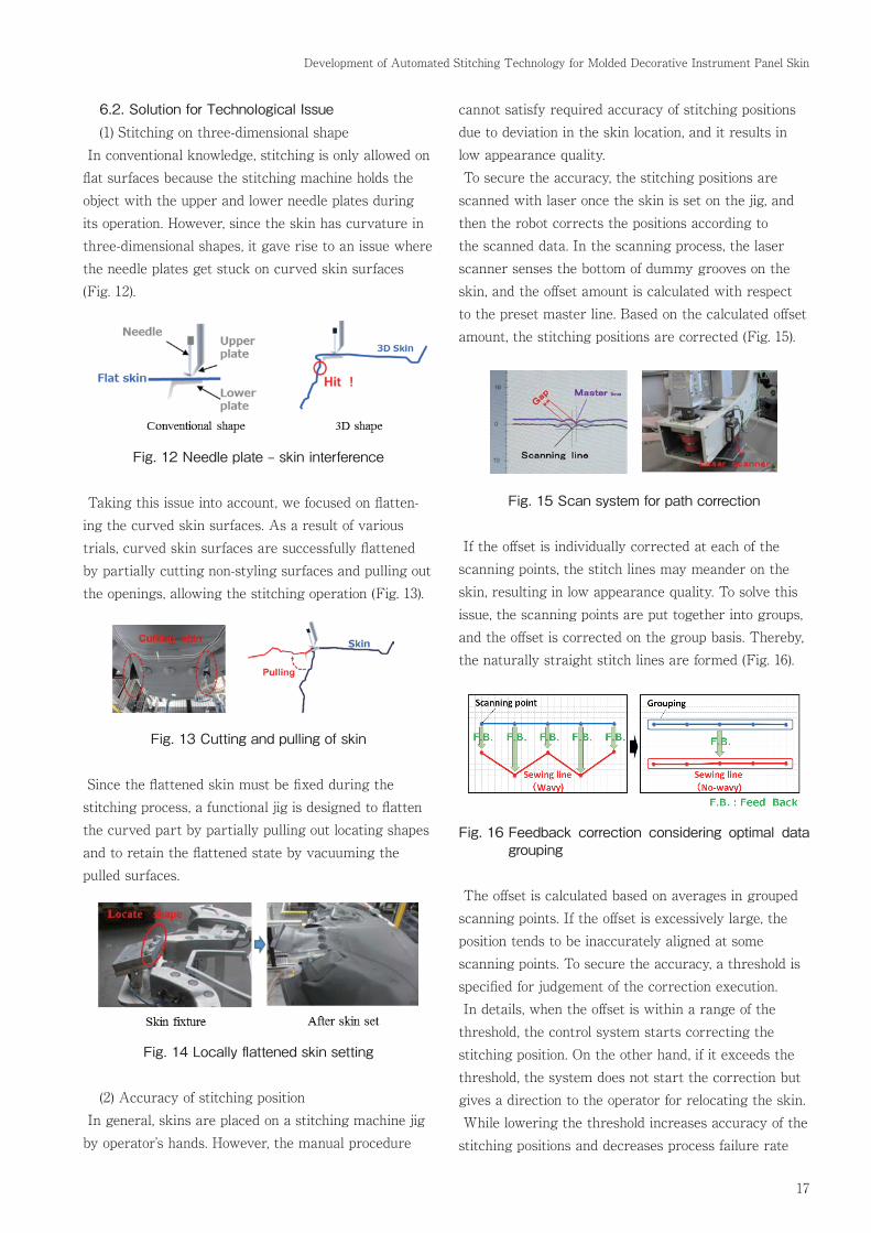
cannot satisfy required accuracy of stitching positions due to deviation in the skin location, and it results in low appearance quality. To secure the accuracy, the stitching positions are scanned with laser once the skin is set on the jig, and then the robot corrects the positions according to the scanned data. In the scanning process, the laser scanner senses the bottom of dummy grooves on the skin, and the offset amount is calculated with respect to the preset master line. Based on the calculated offset amount, the stitching positions are corrected (Fig. 15).
Fig. 15 Scan system for path correction
If the offset is individually corrected at each of the scanning points, the stitch lines may meander on the skin, resulting in low appearance quality. To solve this issue, the scanning points are put together into groups, and the offset is corrected on the group basis. Thereby, the naturally straight stitch lines are formed (Fig. 16).
Fig. 16 Feedback correction considering optimal data grouping
The offset is calculated based on averages in grouped scanning points. If the offset is excessively large, the position tends to be inaccurately aligned at some scanning points. To secure the accuracy, a threshold is specified for judgement of the correction execution. In details, when the offset is within a range of the threshold, the control system starts correcting the stitching position. On the other hand, if it exceeds the threshold, the system does not start the correction but gives a direction to the operator for relocating the skin. While lowering the threshold increases accuracy of the stitching positions and decreases process failure rate

18
CALSONIC KANSEI TECHNICAL REVIEW vol.12 2016
in misalignment, the number of skin relocating opera-tions increases. Conversely, while raising the threshold decreases the positional accuracy and increases the process failure rate, the number of skin relocating operations decreases. Therefore, an optimal threshold is specified so that highly efficient operations and accurate positioning are achieved in the automated process (Fig. 17).
Fig. 17 Revision limit for stitch quality
7. Closing Remarks The automated stitching technology introduced in this report is applied to the molded skin for Nissan Maxima and Titan which have been mass-produced in North America since 2015. It is considered that this technol-ogy is applicable and expandable in global production bases because skillful craftsmen are not required in the automated process. Lastly, the author would like to express deep ap-preciation to all the contributing parties in Nissan and Calsonic Kansei North America for great cooperation in this development.
Masaharu Nagatsuka Akira Saito