new uwb transceivers to thwart theft p.6
TRANSCRIPT

www.EmbeddedSystemsEngineering.com
September/October 2014
Guiding Embedded Designers on Systems and Technologies
New UWB Transceivers To Thwart Theft p.6
MISRA Matters
What’s Fueling the Drive to High Reliability?
Engineers’ Guide to Automotive Embedded
p.11
Overcome Mobile Graphics Pitfalls
Engineers’ Guide to Embedded Linux &
Android p.24
Automotive Sponsors
Bluetooth Low Energy Boosts Security
Engineers’ Guide to LTE & 4G
p.30
Advanced Image Stabilization
Engineers’ Guide to Smartphone, Tablet &
Wearables p.38
LTE/4G SponsorEmbedded Linux & Android Sponsor
Smartphone/Tablet/Wearables Sponsor
The Microchip name and logo, the Microchip logo and MOST are registered trademarks of Microchip Technology Incorporated in the U.S.A. and other countries.All other trademarks are the property of their registered owners. © 2014 Microchip Technology Inc. All rights reserved. 8/14 DS00001813A
microchip.com/automotive
Scalable Automotive Network Solutions
Ethernet, MOST® technology and USB solutions to automotive suppliers for over ten years. Our MOST technology and USB solutions are the de facto standards for in-vehicle infotainment and consumer device connectivity
allowing you to focus your efforts on application software development.
Application Examples Body control
HMI
Top-view camera Infotainment head unit Smart sensors


2 EMBEDDED SYSTEMS ENGINEERING September/October 2014
FROM THE EDITOR
Embedded Systems Engineering is published by Extension Media LLC, 1786 18th Street, San Francisco, CA 94107. Copyright © 2014 by Extension Media LLC. All rights reserved. Printed in the U.S.
Vice President & Publisher
Clair Bright
Editorial
Editor-in-Chief
Chris Ciufo
Managing Editor
Anne Fisher
Contributing Editor
Caroline Hayes
Creative/Production
Production Manager
Spryte Heithecker
Graphic Designers
Nicky Jacobson
Caldin Seides
Media Coordinator
Yishian Yao
Senior Web Developer
Slava Dotsenko
Mariam Moattari
Advertising / Reprint Sales
Vice President, Sales
Embedded Electronics Media Group
Clair Bright
(415) 255-0390 ext. 15
Sales Manager
Michael Cloward
(415) 255-0390 ext. 17
Marketing/Circulation
Jenna Johnson
To Subscribe
www.eecatalog.com
Embedded Systems Engineering 2014www.embeddedsystemsengineering.com
I recently drove Ford’s Platinum Edition Fusion 4-door, an awesome car with MyFord Touch, Microsoft Sync, and an IVI head unit by Sony. Loved the car
(powerful! Quiet!); hated the three confusing UI LCD screens (two surrounding the speedometer, plus the center console). I never connect my smartphone via USB or Bluetooth to a rental: will my contacts stay in memory? Has someone installed the equivalent of a mobile keystroke logger to extract my passwords or intercept my email? These are mere privacy and identity concerns.
Hey, I’m paranoid, but totally justified.
The Fusion had a passive smart key that I kept in my pocket. I need only touch the door handles or truck latch to unlock/lock the car. A dash Start/Stop button worked flawlessly. But I never had faith upon walking away that the car would lock automati-cally. Turns out, a thief can jam the signals between key and car, preventing it from locking (bye-bye valuables). As DecaWave points out in this issue, a relay attack can intercept all signals and later rebroadcast them as a dummy key. Poof! Car’s stolen. These are theft concerns.
As has been proven in the past, hackers with physical access to a vehicle—USB, OBDII port, even the CD player—can load code that affects MCU/ECU functions. In a worst-case scenario, airbag, brakes, engine management, fuel, throttle and other functions can be hacked, with deathly results. Messing with the engine at freeway speeds dis-ables power brakes, airbags, and makes steering and stopping extremely difficult (e.g., GM ignition switches; Toyota unintended acceleration). It’s possible to infiltrate even the tire pressure monitoring system, or TPMS, suppressing “low pressure” signals warning of a future blowout. All are extreme safety concerns.
These safety-critical hacks have so far required physical access to the car. Auto OEMs are adding 4G wireless Internet connectivity in-vehicle, 802.15.4 vehicle-to-vehicle (V2V) and vehicle-to-infrastructure (smart traffic) connectivity. Plus Bluetooth, RFID, NFC and even FM RDS. And with these moves, legitimate concerns about remote hacking are multiplying. Even if the Internet connection is via a driver’s own smartphone, the car is now a node with one or more IP addresses visible on the ‘net.
As reported by CNET.com and IEEE Spectrum, at this year’s Black Hat/DEF CON con-ference, researchers Chris Valasek of IOActive and co-author Charlie Miller presented a paper showing remote hacking is difficult, but possible. Cars with safety-critical systems on the same CANbus as the IVI are most vulnerable. Cars with hardware partitioning and separate networks—like defense systems using ARINC-653 or DO-254 architectures—would be very difficult (e.g., Audi’s A8). RTOS vendors QNX, Mentor Graphics, LynuxWorks, Wind River and Green Hills all provide partitioned operating systems meant to address software separation so the IVI can’t breach criti-cal functions.
A new group called “I Am The Cavalry” aims to start a “Five Star Automotive Cyber Safety Program,” encouraging auto OEMS to address hacking concerns. Excellent reference data is available at https://www.iamthecavalry.org/domains/automotive.
And what of self-parking and self-driving cars? The Fusion has an optional self-park-ing system that works frighteningly well, and Google’s cars are nearing certification for use in limited applications.
Yet I’m completely uncomfortable with this kind of autonomy as long as there’s a chance someone could hack my car and sound the horn without me. I’m following these developments closely.
Hacking Your Car—from Hubs to HornExcitement about the connected car can turn to hassles or horror.By Chris A. Ciufo, Editor
Extension Media, LLC Corporate Office
President and Publisher
Vince Ridley
(415) 255-0390 ext. 18
Vice President & Publisher
Clair Bright
Vice President, Business Development
Melissa Sterling
Human Resources / Administration
Rachael Evans
Special Thanks to Our Sponsors

locate, communicate, accelerate
LTE category 4: 150 Mb/s download, 50 Mb/s upload
Layout-compatible with u-blox 2G, 3G & CDMA modules
Variants for America, Europe and Asia; supports VoLTE
Seamless interface to u-blox GNSS & CellLocate® indoor positioning
LGA and Mini PCIe packages
Industry’s smallest LTE/HSPA+/GPRS modules
TOBY-L2 series High-speed LTE multimode modules
www.u-blox.com
TOBY-L2 series24.8 x 35.6 x 2.6 mm

4 EMBEDDED SYSTEMS ENGINEERING September/October 2014
IN THIS ISSUE
Features
COVER STORY
Automotive Security: Why UWB Measures Up
By Mickael Viot, DecaWave 6
Automotive Embedded
Security of Embedded Automotive Software:
How Compliance with MISRA Can Help
By Dr. Paul Anderson, GrammaTech 10
[Advertorial] Trends in Vehicle Tracking Technology
By Brad Sherrard, Carl Fenger, u-blox 16
Automotive Electronics Fuels Need for High-
Reliability Devices
By Dr. Raik Brinkmann, OneSpin Solutions 18
Product Showcases
Hardware
Components (Processors, DSPs, FPGAs, IP etc.)Microchip Technology 22, 23
Embedded Linux & Android
Clear the Mobile Graphics Thicket
By Peter Harris, ARM 24
Product Showcases
Low-Power Boards & Modules
IndustrialEMAC, Inc. 29
Departments
From the Editor 2
CONTENT
LTE & 4G
Increasing Wireless Security with Bluetooth Low
Energy
By Jennifer Gibbs, Laird 30
[Advertorial] The LTE-connected car, the next hot
“consumer device”
By u-blox 36
Smartphone & Tablet Design
Advanced Image Stabilization Techniques for
Tablet Camera Performance
By Mark Aaldering, ROHM Semiconductor 38
We’ve never
discontinued a
product in 30 years
Embedded
systems that are
built to endure
Unique embedded
solutions add value
for our customers
Support every step
of the way with
open source vision
Sup
of th
opeOPEN
Emb
syst
builRUG
GEDWe’v
disc
prodLON
G L
IFE Uniq
solu
for oORIG
INAL
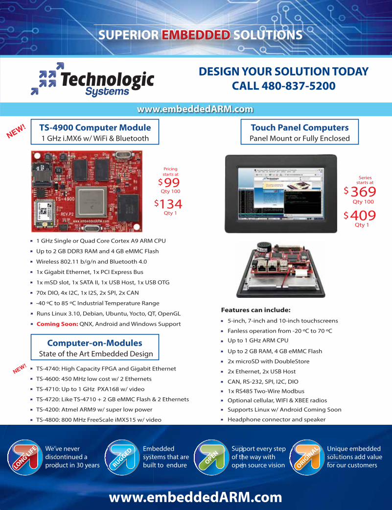
DESIGN YOUR SOLUTION TODAY
CALL 480-837-5200
134$
Qty 10099$
starts at
Pricing
Qty 1
TS-4900 Computer Module1 GHz i.MX6 w/ WiFi & Bluetooth
TS-4740: High Capacity FPGA and Gigabit Ethernet
TS-4710: Up to 1 GHz PXA168 w/ video
TS-4600: 450 MHz low cost w/ 2 Ethernets
TS-4200: Atmel ARM9 w/ super low power
1 GHz Single or Quad Core Cortex A9 ARM CPU
-40 ºC to 85 ºC Industrial Temperature Range
1x Gigabit Ethernet, 1x PCI Express Bus
Wireless 802.11 b/g/n and Bluetooth 4.0
1x mSD slot, 1x SATA II, 1x USB Host, 1x USB OTG
Up to 2 GB DDR3 RAM and 4 GB eMMC Flash
70x DIO, 4x I2C, 1x I2S, 2x SPI, 2x CAN
TS-4800: 800 MHz FreeScale iMX515 w/ video
TS-4720: Like TS-4710 + 2 GB eMMC Flash & 2 Ethernets
Touch Panel ComputersPanel Mount or Fully Enclosed
Features can include:
Qty 1409Qty 100
369$starts at
$
2x Ethernet, 2x USB Host
2x microSD with DoubleStore
Fanless operation from -20 ºC to 70 ºC
1x RS485 Two-Wire Modbus
Optional cellular, WIFI & XBEE radios
Headphone connector and speaker
5-inch, 7-inch and 10-inch touchscreens
CAN, RS-232, SPI, I2C, DIO
Supports Linux w/ Android Coming Soon
Up to 1 GHz ARM CPU
Up to 2 GB RAM, 4 GB eMMC Flash
Series
Computer-on-ModulesState of the Art Embedded Design
Runs Linux 3.10, Debian, Ubuntu, Yocto, QT, OpenGL
Coming Soon: QNX, Android and Windows Support
www.embeddedARM.com
6 EMBEDDED SYSTEMS ENGINEERING September/October 2014
ESE FEATURE
Automotive Security: Why UWB Measures UpWhen IEEE ratified 802.15.4a it opened the way to highly accurate tracking
using wireless technology for the automotive and other industries. Now,
with a new breed of integrated Ultra Wide Band (UWB) transceivers
debuting, a disturbing criminal trend might just be stopped in its tracks.
By Mickael Viot, DecaWave
Developments in vehicle security over recent years have made it
increasingly difficult for thieves to steal vehicles by conventional
means. Statistics show that on a global scale the number of vehicle
thefts has been steadily declining over the past 10 years. However,
in developed countries the latest data shows that they are starting to
rise again.
Surprisingly, the main reason is linked to… the car key.
Keyless passive entry systems to be exact.
CURRENT PASSIVE ENTRY AND START SYSTEMS…More and more modern cars are equipped with a passive entry and
start system. Introduced on high-end cars in the late 90’s, this tech-
nology is democratizing and will soon equip more than 50% of cars.
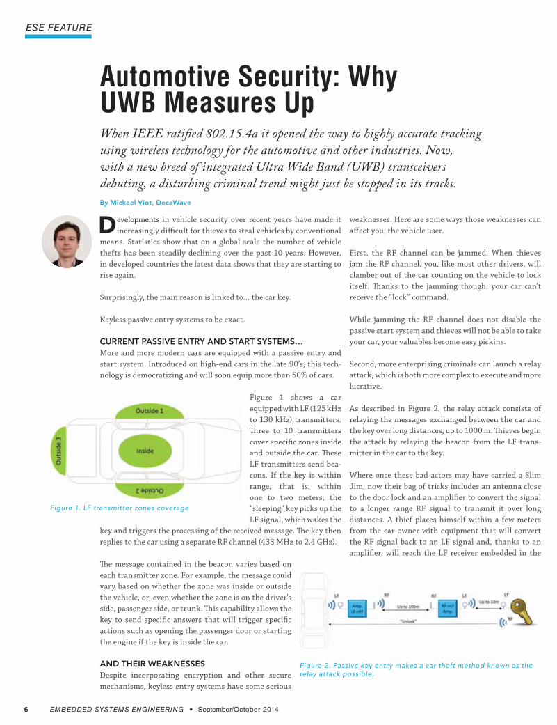
Figure 1 shows a car
equipped with LF (125 kHz
to 130 kHz) transmitters.
Three to 10 transmitters
cover specific zones inside
and outside the car. These
LF transmitters send bea-
cons. If the key is within
range, that is, within
one to two meters, the
“sleeping” key picks up the
LF signal, which wakes the
key and triggers the processing of the received message. The key then
replies to the car using a separate RF channel (433 MHz to 2.4 GHz).
The message contained in the beacon varies based on
each transmitter zone. For example, the message could
vary based on whether the zone was inside or outside
the vehicle, or, even whether the zone is on the driver’s
side, passenger side, or trunk. This capability allows the
key to send specific answers that will trigger specific
actions such as opening the passenger door or starting
the engine if the key is inside the car.
AND THEIR WEAKNESSES Despite incorporating encryption and other secure
mechanisms, keyless entry systems have some serious
weaknesses. Here are some ways those weaknesses can
affect you, the vehicle user.
First, the RF channel can be jammed. When thieves
jam the RF channel, you, like most other drivers, will
clamber out of the car counting on the vehicle to lock
itself. Thanks to the jamming though, your car can’t
receive the “lock” command.
While jamming the RF channel does not disable the
passive start system and thieves will not be able to take
your car, your valuables become easy pickins.
Second, more enterprising criminals can launch a relay
attack, which is both more complex to execute and more
lucrative.
As described in Figure 2, the relay attack consists of
relaying the messages exchanged between the car and
the key over long distances, up to 1000 m. Thieves begin
the attack by relaying the beacon from the LF trans-
mitter in the car to the key.
Where once these bad actors may have carried a Slim
Jim, now their bag of tricks includes an antenna close
to the door lock and an amplifier to convert the signal
to a longer range RF signal to transmit it over long
distances. A thief places himself within a few meters
from the car owner with equipment that will convert
the RF signal back to an LF signal and, thanks to an
amplifier, will reach the LF receiver embedded in the
Figure 1. LF transmitter zones coverage
Figure 2. Passive key entry makes a car theft method known as the relay attack possible.

8 EMBEDDED SYSTEMS ENGINEERING September/October 2014
ESE FEATURE
key. Once the key gets the beacon message, it will answer as usual with
an “unlock” command. This command will be picked and relayed as
described above to travel back to the car.
Now that the thieves are in the car, they don’t have to settle just for
stealing what’s inside. They simply position the antenna close to the
transmitter in charge of the “inside” zone, triggering the activation of
the passive start system. Your car is gone.
REPELLING RELAY ATTACKS Nowadays key fobs all use advanced security techniques like encryp-
tion to secure the communication between the key and the car. But
if someone manages to relay the communication, all this security is
useless.
One option to avoid relay attack is to measure the real physical dis-
tance between the car and the key. If the car detects that the key is not
physically close, it will simply ignore the commands received.
Measuring RF signal strength is one way to obtain a distance measure-
ment. But doing so relies on the assumption that the signal strength
and distance have a deterministic relationship, according to the Friis
equation. Unfortunately, the Friis equation is only applicable in free
space. In an environment with multi-path, interference and lack of
sight, the range estimate will have an accuracy of tens of meters.
A second technique consists of measuring the Time of Flight of the
RF signal to estimate the distance between the transmitter and the
receiver. There have been attempts to build time of flight systems using
standard narrowband RF like Bluetooth or other 2.4 GHz signals.
The problem here is that due to the narrow bandwidth, the rising edge
of the signal is slow, and it is difficult to determine the exact time of
arrival in multi-path and low-signal-to-noise-ratio environments (see
Figure 3), resulting in an accuracy of several meters, with reliability
still very dependent on the environment.
UWB TAKES ON MEASUREMENT TO STOP PASSIVE-AGGRESSIVE BEHAVIORUltra Wideband (UWB) may finally offer the performance needed for
accurate and reliable distance measurement. The UWB signal consists
of narrow pulses, typically no more than 2 ns wide. This makes it
highly immune to multi-path and interference (see Figure 4). Being
Ultra Wide Band, with a bandwidth between 500 MHz
and 1.2 GHz, this technology is also much more diffi-
cult to jam.
OPERATION ONLY WITHIN A GIVEN DISTANCE FROM THE VEHICLE UWB technology allows Line-of-Sight ranges of greater
than 200 m. However, the in-vehicle unit can be config-
ured to only take action when the measured distance is
less than a certain vehicle manufacturer defined value.
Because UWB is capable of achieving 10 cm accuracy
with 100% reliability, manufacturers could define very
accurate zones, triggering the lock release mechanism
only when the driver is within close proximity to the
vehicle.
DETECTING ON WHICH SIDE OF THE VEHICLE THE FOB IS LOCATEDAs we’ve seen earlier, the latest generation cars using
traditional LF and RF technologies are capable of
knowing from which side of the car the driver is
approaching, triggering specific actions like opening a
specific door or the trunk.
But using UWB, how does the car know which car door
or trunk to release?
A single two-way ranging exchange between one in-
vehicle unit and a fob is sufficient to measure how far
away the fob is from the vehicle. However, having only
one piece of information—a single distance—available
is not enough to determine on which side of the vehicle
the fob is located.
Knowing on which side of the vehicle the fob is located
takes two pieces of information. These two pieces of
information could be, for example, two distances from
two in-vehicle units, provided of course that these in-
Figure 3. Narrowband signal in presence of multi-path and noise
Figure 4. UWB offers high immunity to multi-path and noise.

Two Premier Conferences Showcasing the Embedded Systems Industry
Resolving the Technical and Business Challenges of Getting
Connected to the Internet of Things
Resolving the Technical Aspects and Business
Challenges of Designing with Multicore
Processors
Plan now to attend! MAY 6 -7, 2015 Santa Clara, CA USA
For information on exhibiting or sponsoring contact: Clair Bright +1 415-225-0390 x15 or [email protected]
10 EMBEDDED SYSTEMS ENGINEERING September/October 2014
ESE FEATURE
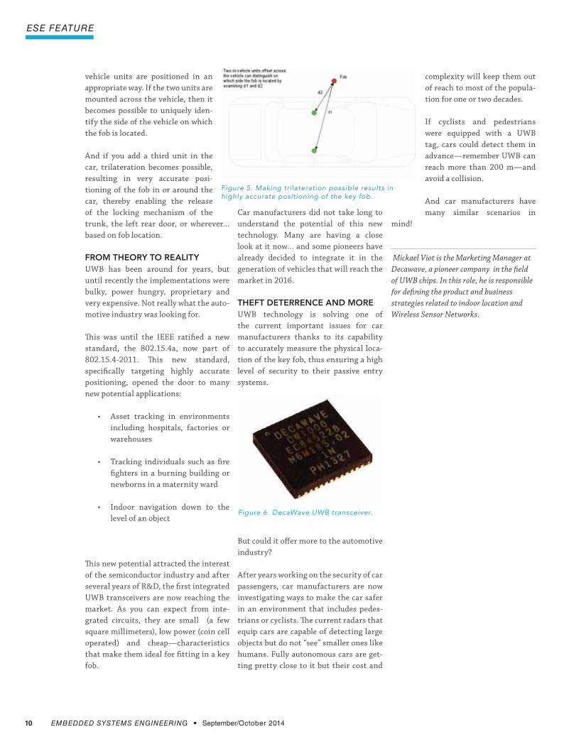
vehicle units are positioned in an
appropriate way. If the two units are
mounted across the vehicle, then it
becomes possible to uniquely iden-
tify the side of the vehicle on which
the fob is located.
And if you add a third unit in the
car, trilateration becomes possible,
resulting in very accurate posi-
tioning of the fob in or around the
car, thereby enabling the release
of the locking mechanism of the
trunk, the left rear door, or wherever…
based on fob location.
FROM THEORY TO REALITYUWB has been around for years, but
until recently the implementations were
bulky, power hungry, proprietary and
very expensive. Not really what the auto-
motive industry was looking for.
This was until the IEEE ratified a new
standard, the 802.15.4a, now part of
802.15.4-2011. This new standard,
specifically targeting highly accurate
positioning, opened the door to many
new potential applications:
including hospitals, factories or
warehouses
fighters in a burning building or
newborns in a maternity ward
level of an object
This new potential attracted the interest
of the semiconductor industry and after
several years of R&D, the first integrated
UWB transceivers are now reaching the
market. As you can expect from inte-
grated circuits, they are small (a few
square millimeters), low power (coin cell
operated) and cheap—characteristics
that make them ideal for fitting in a key
fob.
Car manufacturers did not take long to
understand the potential of this new
technology. Many are having a close
look at it now… and some pioneers have
already decided to integrate it in the
generation of vehicles that will reach the
market in 2016.
THEFT DETERRENCE AND MOREUWB technology is solving one of
the current important issues for car
manufacturers thanks to its capability
to accurately measure the physical loca-
tion of the key fob, thus ensuring a high
level of security to their passive entry
systems.
But could it offer more to the automotive
industry?
After years working on the security of car
passengers, car manufacturers are now
investigating ways to make the car safer
in an environment that includes pedes-
trians or cyclists. The current radars that
equip cars are capable of detecting large
objects but do not “see” smaller ones like
humans. Fully autonomous cars are get-
ting pretty close to it but their cost and
Figure 5. Making trilateration possible results in highly accurate positioning of the key fob.
Figure 6. DecaWave UWB transceiver.
complexity will keep them out
of reach to most of the popula-
tion for one or two decades.
If cyclists and pedestrians
were equipped with a UWB
tag, cars could detect them in
advance—remember UWB can
reach more than 200 m—and
avoid a collision.
And car manufacturers have
many similar scenarios in
mind!
Mickael Viot is the Marketing Manager at
Decawave, a pioneer company in the field
of UWB chips. In this role, he is responsible
for defining the product and business
strategies related to indoor location and
Wireless Sensor Networks.

www.eecatalog.com/automotive EMBEDDED SYSTEMS ENGINEERING 11
engineers guide to Automotive Embedded
Security of Embedded Automotive Software: How Compliance with MISRA Can HelpThe new reality for automotive software security is a complicated, but advanced
static analysis can help.
By Dr. Paul Anderson, GrammaTech
The proliferation of network-enabled vehicles is altering the defini-
tion of safety in automobiles. Previously, auto safety concerns were
dominated by active and passive passenger protection systems, however
now the discussion extends to ways to prevent malicious hackers com-
promising vehicle safety. It’s also interesting to note from a historical
perspective that the DNA of car manufacturers has traditionally been
mechanical. But now that identity is transforming rapidly to include
software.
A key factor that makes the growing fleet of network-connected auto-
mobiles an attractive target for hackers is the sheer volume of potential
targets. Unlike the medical device industry—which is also undergoing a
radical shift in exposure to potential exploits because of increased con-
nectivity—cars are part of most people’s daily lives. So for malicious
hackers looking for notoriety, cracking the code of an automobile can lend
itself to dramatic publicity.
What is most disturbing about the growing threat of malicious attacks
against automobiles is the potential for physical destruction and loss of
life they pose. Attacks against cars can run the gamut from trivial, such
as the disruption of an entertainment system to devastating, such as
hijacking control of key safety systems including acceleration, braking
and steering. Because of this growing threat, it is essential for automobile
manufacturers and their component suppliers to be more proactive with
respect to securing the code in our cars.
One of the reasons that software poses a security risk in automobiles is
the widespread use of the C programming language. A badly written C
program can contain bugs that give an attacker enough of a foothold to
take control of the car’s electronics. Unfortunately such bugs are easy for
programmers to introduce and overlook. A very effective way of defending
against these defects is to restrict the programmer’s use of the language
by prohibiting the more risky constructs. MISRA-C is one such standard
whose use has been growing for safety-critical applications.
MISRA-C was developed by the Motor Industry Software Reliability
Association, which aims to foster safety, reliability, and portability of
embedded programs used in automotive components. Although not
designed specifically for security, there is a large overlap between the
kinds of defect that cause safety issues and those that cause security vul-
nerabilities, so adherence to the standard is a potent way to guard against
both issues.
NEW ATTACK SURFACES PROLIFERATE IN MODERN EMBEDDED AUTOMOTIVE SYSTEMSThe new reality for automotive software security is a com-
plicated one, with multiple new exploit paths emerging
as cars and their components become more connected.
Today, modern autos run what is essentially their own
internal network called the Controller Area Network
(CAN). This network connects a broad array of embedded
processors such as those used to power the entertainment
system, control the brakes, manage engine performance,
and monitor tire air pressure.
From a security perspective, every networked embedded
component in a car is a potential beachhead for attackers to
use to mount a further assault on other connected devices
and components. Within the car’s software system, the
main diagnostic port is the juiciest of all potential exploit
points—but attacking a system in this manner requires
physical access to the port itself. That said, there are other
less obvious points of exposure ports that also pose sig-
nificant security risks. Attackers have been successful at
breaking into a car’s electronic systems through the CD
player and the cellular network. A modern car now has
many other input channels, including USB ports and Blue-
tooth connections, and all of them are potential openings
through which an attack might be mounted.
Figure 1. From a security perspective, every networked component in a car, such as this entertainment system, is a potential beachhead for attackers to mount further assaults on other connected devices and components.

12 EMBEDDED SYSTEMS ENGINEERING September/October 2014
engineers guide to Automotive Embedded
AS NEW CODE BASES OVERTAKE LEGACY CODE, RISK ACCELERATESIn the automotive industry, there are many
legacy code bases that run connected com-
ponents. But as software plays a greater
role in driving consumer choice, new code
is becoming the norm. This leaves vendors
struggling to determine which is safer – the
new code or the old? Unfortunately, there
is no hard and fast rule here. While newer
code is often built to adhere to standards
such as MISRA, it nevertheless carries the
risks all new code bases do—because it
hasn’t been battle-tested in the field like
legacy code, there may be potential defects
lurking within.
Given that software in automobiles is
subject to a remarkably long development
lifecycle, it is essential that automotive
software developers adopt the most up-to-
date quality and safety standards rapidly.
After all, once the code that powers a
component makes it to market, it may
be 3–5 years old and will face potential
attacks that were not known during its
development. The only way to inoculate it
against these future exploits is to use the
most sophisticated tools available today to
protect it.
RATES OF MISRA ADOPTION STILL LAGThe embedded software development
teams that we work with are certainly
aware of the MISRA standard and under-
stand what it aims to achieve. However, the
level of adherence to the standard varies
significantly by maker and geography.
Data from VDC Research underscores
there is much room for improvement. Take
a look at the data in Table 1.
According to Andre’ Girard, Senior Ana-
lyst at VDC Research, it’s clear that those
manufacturers that comply completely
with MISRA C and MISRA C++ are in a
small minority. Further, VDC notes that
US automakers’ adoption of process stan-
dards has historically trailed those of their
European counterparts. This is a potential
competitive weakness for US manufac-
Table 1: MISRA-C and MISRA-C++ Rates of Adherence within the Auto/Rail/Transportation vertical. Source: VDC Research, 2014.
Key Requirements for
Static Analysis Tools
Precision - The tool can parse code exactly the
same way the compiler parses it. All compilers
are different, and analysis tools that don’t take
this into account can provide false results.
Whole-program analysis—The tool can track
how information flows between procedures and
across compilation unit boundaries.
Flow-, context-, and path-sensitive analysis—
The tool can be precise about finding and
reporting defects.
ELIMINATE INFEASIBLE PATHSThe tool uses this to cut down on the number
of false-positive results reported. The best tools
use advanced techniques such as SMT solvers.
Native MISRA checkers—The tool uses native
MISRA checkers to assure compliance to the
standard. Use of partnerships or compliance
only to previous versions of the standard will
not provide adequate performance.
turers. As the US automobile
industry continues to regain
its leadership position in sales
and quality, it should take the
lead within the automotive
industry in this important
area. The US cannot risk
falling behind in software
security and safety practices.
AUTOMOBILE SOFTWARE RELIES ON C, AND C IS…WELL…A HOT MESSIn embedded software development for
automobiles, C still holds the title as the
most popular choice of language. Although
other languages such as Ada, C++, and Java
are sometimes employed, over half of the
code running on embedded automotive
systems today is hand-written C.
C is a great language in many respects—for
auto manufacturers it holds special utility
because the language excels at interfacing
between multiple hardware devices.
Regrettably, C is also an extremely
hazardous language. Its very flexibility
means it is easy for a programmer to
make mistakes. Because the standard of
what constitutes a valid C program is very
liberal, compilers are very bad at detecting
many different kinds of errors. Further,
the standard is riddled with ambiguities.
Therefore, code that works perfectly well
with one compiler may fail when a different
compiler is used because each compiler
has a different valid interpretation of the
standard.
All of this makes C programs very sus-
ceptible to serious memory-access defects
such as buffer overruns, null pointer
exceptions, and many others. Other
classes of errors such as resource leaks, use
of uninitialized memory, and use-after-
free errors are also endemic and abundant
in C programs. When concurrency is used,
defects such as data races and deadlocks
are easy to introduce yet difficult to find.
MISRA + ADVANCED STATIC ANALYSIS IS A TRUE EMBEDDED GAME CHANGEROne of the most important aspects of
using MISRA C is that there are now auto-
IndustryCoding
StandardNot adhering
toCompletely complying
Selectively enforcing based on internal quality goals Don’t know
Auto / Rail / Transportation MISRA C 31.1% 17.8% 26.7% 24.4%
Auto / Rail / Transportation MISRA C++ 13.3% 20.0% 44.4% 22.2%

The Microchip name and logo, the Microchip logo and PIC are registered trademarks of Microchip Technology Incorporated in the U.S.A. and other countries.All other trademarks are the property of their registered owners. © 2014 Microchip Technology Inc. All rights reserved. 5/14 DS00001745A
Driving Capacitive Touch Sensing Innovation
microchip.com/mtouch
Capacitive Touch Keys, Sliders and Proximity
Easy path to system integrationTurnkey products
PIC® MCU portfolio
High noise immunity and low emissions Extend battery life with eXtreme
Proximity sensing up to 25 cm
Metal Over Cap Technology Effective for polished or brushed metal surfaces including stainless steel and aluminum Senses through gloves Enables waterproof designs
Touch Pad Controllers XY Touch
14 EMBEDDED SYSTEMS ENGINEERING September/October 2014
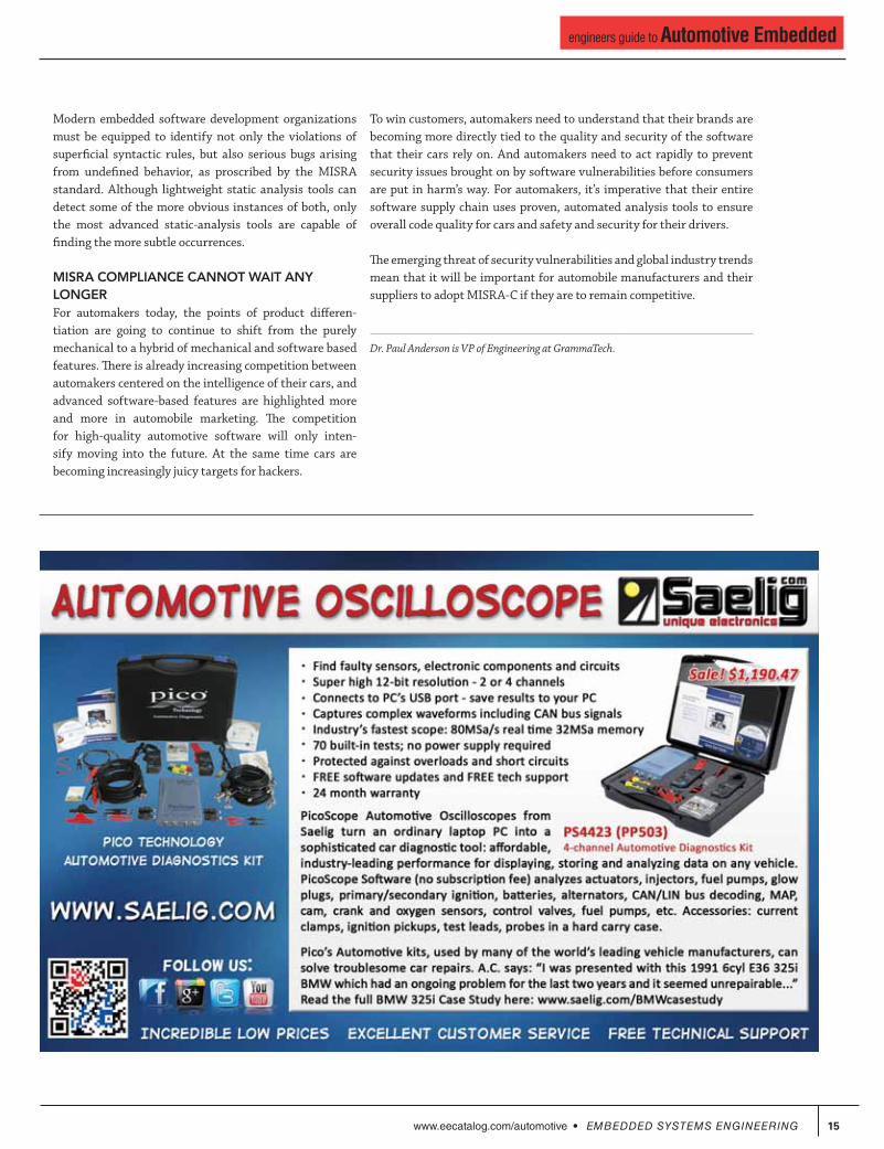
engineers guide to Automotive Embedded
mated static analysis tools available to find violations of
the standard. Because tool support is so important, it is
helpful to understand the kinds of problems that static
analysis tools can detect. Some tools can only reason
about superficial syntactic properties of the code, whereas
the more advanced tools have deep semantic knowledge
of the entire program and so can detect much more subtle
and dangerous defects.
The current MISRA C:2012 standard labels each rule with
its decidability. A rule that is labeled decidable means
that it is possible for a static analysis tools to find all such
violations with no false positives; most of the superficial
syntactical rules are marked as such. In contrast, a rule
that is labeled undecidable means that it is in general
provably impossible for a static analysis tool to find all vio-
lations without any false positives. This is not to say that
static analysis is not recommended for such rules — it just
means that tools may fail to find some violations and may
also report some false positives.
One such example is rule 2.2: “There shall be no dead code.”
Dead code is defined as any operation whose result does
not affect the behavior of the program. It is easy to see how
this is a hard property to detect — an analysis tool must be
able to understand the semantics of all possible executions
of the program and to be able to tell what portions of that
code have no effect. Whereas there may be some instances
that are easily detectable, finding all instances with no
false positives is impossible.
Although static analysis tools cannot detect all violations
of undecidable rules, it is critically important that tools be
used to detect as many violations as possible because that
is where the most critical bugs are likely to hide. There are
two clauses in the standard that are particularly relevant
here — one rule and one directive:
or critical unspecified behavior.”
-
mized.”
These are arguably the two most important clauses in the
entire standard. Between them they target the Achilles
heel of C programs. Undefined behavior is explicitly
discussed in the ISO standard for C (Annex J in the C99
document), and covers a broad range of aspects of the
language. It often comes as a surprise to C programmers
to learn that according to the standard, if a C program
invokes undefined behavior, it is perfectly legal for that
program to do anything at all. This is sometime facetiously
referred to as the “catch fire” semantics, because it gives
the compiler liberty to set your computer on fire.
Of course compiler writers are not pyromaniacs (we hope), and they try
to do the most sensible thing in the face of undefined behavior. If the
undefined behavior is detectable by the compiler, then the sensible thing
is to have the compiler emit a compilation error. However if the undefined
behavior is not detectable by the compiler, then a compiler writer has
essentially no choice but to assume it cannot happen.
Undefined behavior is not a rarely-encountered niche; the C99 standard
lists 191 different varieties, and it turns out that even some apparently
benign things are classified as undefined behavior. Consequently it can be
hard for even the most careful programmer to avoid undefined behavior.
Unspecified behavior is less hazardous, but has its own pitfalls. In this
case the standard specifies a set of legal behaviors, but leaves it to the
compiler writer to choose which to use. This gives the compiler writer
latitude to choose the interpretation that has the best performance, but it
means that code can have different semantics when compiled by different
compilers.
What is clear is that undefined behavior is almost always something that
a programmer should be concerned about. Many of the most serious bugs
are those that arise because of undefined behavior. For example:
None of these are singled out as forbidden in the MISRA standard, but are
instead covered under the umbrella of Rule 1.3 and Directive 4.1. None-
theless, every such bug is a violation of the standard.
Figure 2. An important aspects of using MISRA C is that automated static analysis tools, such as GrammaTech's CodeSonar above, are now available to find violations of the standard.
www.eecatalog.com/automotive EMBEDDED SYSTEMS ENGINEERING 15
engineers guide to Automotive Embedded
Modern embedded software development organizations
must be equipped to identify not only the violations of
superficial syntactic rules, but also serious bugs arising
from undefined behavior, as proscribed by the MISRA
standard. Although lightweight static analysis tools can
detect some of the more obvious instances of both, only
the most advanced static-analysis tools are capable of
finding the more subtle occurrences.
MISRA COMPLIANCE CANNOT WAIT ANY LONGERFor automakers today, the points of product differen-
tiation are going to continue to shift from the purely
mechanical to a hybrid of mechanical and software based
features. There is already increasing competition between
automakers centered on the intelligence of their cars, and
advanced software-based features are highlighted more
and more in automobile marketing. The competition
for high-quality automotive software will only inten-
sify moving into the future. At the same time cars are
becoming increasingly juicy targets for hackers.
To win customers, automakers need to understand that their brands are
becoming more directly tied to the quality and security of the software
that their cars rely on. And automakers need to act rapidly to prevent
security issues brought on by software vulnerabilities before consumers
are put in harm’s way. For automakers, it’s imperative that their entire
software supply chain uses proven, automated analysis tools to ensure
overall code quality for cars and safety and security for their drivers.
The emerging threat of security vulnerabilities and global industry trends
mean that it will be important for automobile manufacturers and their
suppliers to adopt MISRA-C if they are to remain competitive.
Dr. Paul Anderson is VP of Engineering at GrammaTech.

16 Engineers’ Guide to Automotive Embedded 2015
ADVERTORIAL
Trends in Vehicle Tracking TechnologyBrad Sherrard, Carl Fenger, u-blox
Market adoption of vehicle tracking systems is growing fast, with
the majority of commercial vehicles in North America and Europe
already using the technology, and rapid growth occurring in Asian
and emerging markets. A recent market study concluded that the
global vehicle tracking market will grow from $10.91 billion in
2013 to $30.45 billion by 2018, at a Compound Annual Growth
Rate (CAGR) of 22.8% .
The driving factors for adoption of vehicle tracking for both com-
mercial and private vehicles are:
o Lowering of logistics costs: optimization of container
loading, improved routing, stock level optimization, and
improved operational overview
o Providing a better service: real-time and historical posi-
tional reporting
o Increased security: theft detection and traceability of
shipped goods
o Facilitating stolen goods/vehicle recovery and prevention
of fuel theft
o Monitoring of CO2 emissions, fuel efficiency, and vehicle
health
o Driver management and logging of driving behavior
o Rollout of large-scale emergency call systems for private
and commercial vehicles
o Government mandate to include tracking technology in new
vehicles
o Falling cost and size, and increasing performance of satel-
lite positioning receivers and cellular modems
o Facilitating of insurance claims based on accident re-
construction using logged position, direction, speed and
acceleration data.
o Miniaturization of tracking units and antenna allowing
covert mounting and installation in smaller enclosures
o Falling power requirements facilitating longer battery life
and solar powered devices, especially applicable to asset
tracking devices with no connection to the vehicle power
supply
o Easy interfacing to globally available public and proprietary
web and smartphone applications, including modem compat-
ibility with IPv4 and IPv6 (e.g. Google Maps, Google GPS and
numerous vendor-specific applications)
Issues and requirementsThere are several hardware issues when addressing the above men-
tioned scenarios:
Compatibility with multiple Global Navigation Satellite Systems (GNSS) systemsGPS is no longer the only global navigation satellite system avail-
able. The Russian GLONASS is now fully operational, the Chinese
BeiDou and Japanese QZSS systems are partially operational, and
the EU Galileo system will be available by 2019. Requirements
for compatibility with these systems vary from single-system to
multiple system compliance, either one at a time or with parallel
functionality.
These requirements are dictated by where a tracking application
will be used: weak signal environments such as urban canyons
or arctic regions where satellites appear low on the horizon may
necessitate parallel GNSS operation. Government mandate is
Vehicle tracking combines satellite positioning with cellular communications to enable a long list of services for both private and commercial vehicles
u-blox M8 multi-GNSS receiver modules MAX, NEO and LEA supporting GPS, QZSS, GLONASS, BeiDou with dual-GNSS capability

www.eecatalog.com/automotive 17
ADVERTORIAL
Automotive grade componentsLastly, but equally important to all aspects discussed previously,
vehicle tracking applications require automotive grade compo-
nents. As “automotive grade” is a relative term whose definition
is different depending on manufacturers and end-customers, at
the very minimum modem and GNSS components (and all other
electronic components in the design) should qualified according
to AEC-Q100, manufactured in ISO/TS 16949 certified sites, and
fully tested at the factory on a system level. Qualification tests
should be performed as stipulated in the ISO16750 standard:
“Road vehicles – Environmental conditions and testing for elec-
trical and electronic equipment”.
ConclusionVehicle tracking is becoming a defacto requirement for private,
commercial and public transportation. As both GNSS and cel-
lular technologies are in a constant state of flux, it is important
to design tracking systems that address regional satellite and cel-
lular compatibility, positioning in areas where satellite visibility is
degraded or absent, ease of hardware variants and upgrade, sup-
pression of radio inference and conforming to automotive quality
requirements.
Due to the long-life expected of vehicle tracking devices, as well
as reliable performance over large geographical areas, it is best to
base designs not only on the current state of the technology, but
also on the expected lifetime of the system.
also a consideration; in Russia, for example, the ERA-GLONASS
vehicle emergency call system requires GLONASS compatibility. A
similar situation exists in China with BeiDou.
Performance requirements may require vehicle tracking systems
that are compatible with multiple GNSS systems simultaneously:
access to more satellites results in faster time to fix and more reli-
able operation, particularly in high-rise cities.
Operation in areas with poor satellite receptionFor tracking applications, visibility of GNSS satellites is critical
to calculate a position. With GPS/GNSS satellites transmitting
with a power of about 30 watts from a distance of 20 thousand
kilometers, and the requirement to lock onto 4 satellites, tracking
performance and accuracy can become degraded in urban canyons,
when indoors (e.g. inside warehouses, rail stations, park houses),
or when the receiver is within metallic containers. For tracking
applications, this issue can be addressed via several techniques:
Integrated dead reckoning: augmenting GNSS receivers
with sensor data that reports distance and heading changes
from the last known position. This is commonly implemented
in automotive navigation systems to support uninterrupted
navigation within tunnels. Accelerometer readings can also
improve positioning within multi-level park houses or stacked
highways by taking into account vertical displacement. Refer
to u-blox’ embedded dead reckoning GNSS technology.
Hybrid positioning techniques for indoor positioning:
Adding a second parallel system that can estimate position
based on other attributes such as visible mobile or Wi-Fi cells
adds an additional measure of security when GNSS satellite
visibility is blocked: even an approximate location within a
few hundred meters, or even a few kilometers is preferable to
no positional information at all, especially when it comes to
valuable shipments and vehicles (refer to u-blox’ CellLocate®
technology).
Compatibility with multiple cellular standardsRelying on the GSM/GPRS (2G) standard for tracking devices was
easy as it has been uniformly adopted worldwide. GSM/GPRS,
however, is falling prey to next-generation 3G standards, specifi-
cally UMTS/HSPA, CDMA2000 (in the USA) and LTE, all of which
are not uniformly deployed around the world. Specifically, there
are many regional variants of 3G and 4G standards that operate
over different frequency bands.
This highlights the desirability of cellular modems that support
different standards (GSM, UMTS, CDMA, LTE) while retaining
footprint compatibility on the same PCB layout. This reduces
hardware costs when designing tracking systems with regional
variants, or upgrading to the next-generation tracking technology
(ex. 2G to 3G upgrade). Refer to u-blox’ nested design concept for
cellular modules.
Nested modem PCB design is important for creating regional variants of a tracking device, and to allow for future upgrades. Pictured: u-blox SARA, LISA and TOBY modules supporting GSM, UMTS and LTE
CONTACT INFORMATION
u-bloxGlobal HeadquartersZürcherstrasse 68 8800 Thalwil SwitzerlandTel: +41 44 722 74 44 Fax: +41 44 722 74 47 [email protected]
18 EMBEDDED SYSTEMS ENGINEERING September/October 2014
engineers guide to Automotive Embedded
Safety critical design of automotive electronics, including those using FPGAs, falls
under the new ISO 26262 standard. The need for more complex functions and high
performance in an ultra-reliable environment plays a substantial role in automotive
embedded system design.
Field Programmable Gate Arrays (FPGAs) offer flexibility and density at affordable imple-
mentation cost, so it is not surprising that the use of FPGAs in automotive systems is
expanding. With custom devices being expensive to produce, many design teams resorted
to Micro Controller Units (MCUs) for many functions. FPGAs offer an attractive alter-
native to a software only functional model, while retaining the design cost benefits of
the MCU. In addition, modern FPGAs contain convenient hardware functions useful in
automotive applications, and may also be updated in the field. Another area where FPGAs
shine is in boosting performance for compute-intensive automotive applications such as
Advanced Driver Assistance Systems (ADAS).
The traditional approach of running an FPGA
design on the actual hardware to provide a
functional testing environment cannot satisfy
the verification needs of the standards, and
using simulation only improves the situation
slightly. Developers have been using verifica-
tion tools based on formal methods for custom
automotive devices. It’s an approach that can
meet FPGA needs as well.
THE IMPACT OF AUTOMOTIVE FAIL-SAFE REQUIREMENTSToday the simplest of modern vehicles will con-
tain a number of processors, and this runs into
the hundreds of compute elements for high-end
vehicles. Electronics are present throughout
the safety critical components in the car, aid
the driver in its safe operation, and introduce
a new level of comfort. However, if one of these
critical systems fails during operation, the
result is catastrophic. As such, standards have
Automotive Electronics Fuels Need for High-Reliability DevicesAlready working on behalf of custom automotive de-
vices, verification tools based on formal methods are now
helping put FPGAs in the driver’s seat—can mil/aero,
transportation, power generation and other safety-critical
areas be far behind?
By Dr. Raik Brinkmann, OneSpin Solutions
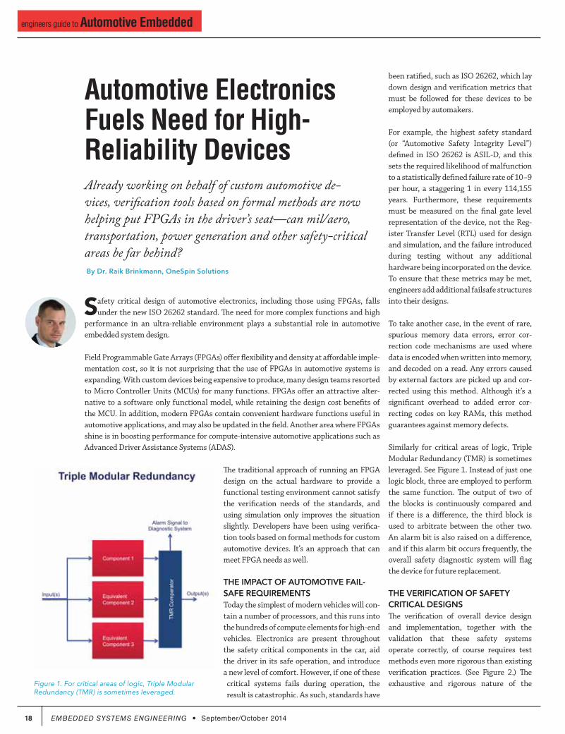
Figure 1. For critical areas of logic, Triple Modular Redundancy (TMR) is sometimes leveraged.
been ratified, such as ISO 26262, which lay
down design and verification metrics that
must be followed for these devices to be
employed by automakers.
For example, the highest safety standard
(or “Automotive Safety Integrity Level”)
defined in ISO 26262 is ASIL-D, and this
sets the required likelihood of malfunction
to a statistically defined failure rate of 10−9
per hour, a staggering 1 in every 114,155
years. Furthermore, these requirements
must be measured on the final gate level
representation of the device, not the Reg-
ister Transfer Level (RTL) used for design
and simulation, and the failure introduced
during testing without any additional
hardware being incorporated on the device.
To ensure that these metrics may be met,
engineers add additional failsafe structures
into their designs.
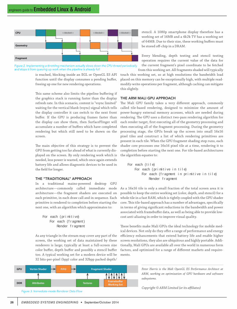
To take another case, in the event of rare,
spurious memory data errors, error cor-
rection code mechanisms are used where
data is encoded when written into memory,
and decoded on a read. Any errors caused
by external factors are picked up and cor-
rected using this method. Although it’s a
significant overhead to added error cor-
recting codes on key RAMs, this method
guarantees against memory defects.
Similarly for critical areas of logic, Triple
Modular Redundancy (TMR) is sometimes
leveraged. See Figure 1. Instead of just one
logic block, three are employed to perform
the same function. The output of two of
the blocks is continuously compared and
if there is a difference, the third block is
used to arbitrate between the other two.
An alarm bit is also raised on a difference,
and if this alarm bit occurs frequently, the
overall safety diagnostic system will flag
the device for future replacement.
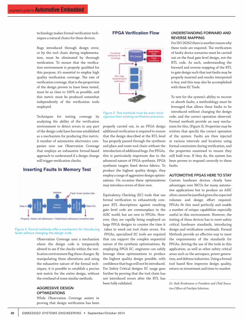
THE VERIFICATION OF SAFETY CRITICAL DESIGNSThe verification of overall device design
and implementation, together with the
validation that these safety systems
operate correctly, of course requires test
methods even more rigorous than existing
verification practices. (See Figure 2.) The
exhaustive and rigorous nature of the

We’ve never
discontinued a
product in 30 years
Embedded
systems that are
built to endure
Unique embedded
solutions add value
for our customers
Support every step
of the way with
open source vision
Sup
of th
opeOPEN
Emb
syst
builRUG
GEDWe’v
disc
prodLON
G L
IFE Uniq
solu
for oORIG
INAL
DESIGN YOUR SOLUTION TODAY
CALL 480-837-5200
134$
Qty 10099$
starts at
Pricing
Qty 1
TS-4900 Computer Module1 GHz i.MX6 w/ WiFi & Bluetooth
TS-4740: High Capacity FPGA and Gigabit Ethernet
TS-4710: Up to 1 GHz PXA168 w/ video
TS-4600: 450 MHz low cost w/ 2 Ethernets
TS-4200: Atmel ARM9 w/ super low power
1 GHz Single or Quad Core Cortex A9 ARM CPU
-40 ºC to 85 ºC Industrial Temperature Range
1x Gigabit Ethernet, 1x PCI Express Bus
Wireless 802.11 b/g/n and Bluetooth 4.0
1x mSD slot, 1x SATA II, 1x USB Host, 1x USB OTG
Up to 2 GB DDR3 RAM and 4 GB eMMC Flash
70x DIO, 4x I2C, 1x I2S, 2x SPI, 2x CAN
TS-4800: 800 MHz FreeScale iMX515 w/ video
TS-4720: Like TS-4710 + 2 GB eMMC Flash & 2 Ethernets
Touch Panel ComputersPanel Mount or Fully Enclosed
Features can include:
Qty 1409Qty 100
369$starts at
$
2x Ethernet, 2x USB Host
2x microSD with DoubleStore
Fanless operation from -20 ºC to 70 ºC
1x RS485 Two-Wire Modbus
Optional cellular, WIFI & XBEE radios
Headphone connector and speaker
5-inch, 7-inch and 10-inch touchscreens
CAN, RS-232, SPI, I2C, DIO
Supports Linux w/ Android Coming Soon
Up to 1 GHz ARM CPU
Up to 2 GB RAM, 4 GB eMMC Flash
Series
Computer-on-ModulesState of the Art Embedded Design
Runs Linux 3.10, Debian, Ubuntu, Yocto, QT, OpenGL
Coming Soon: QNX, Android and Windows Support
www.embeddedARM.com
20 EMBEDDED SYSTEMS ENGINEERING September/October 2014
engineers guide to Automotive Embedded
technology makes formal verification tech-
niques a natural choice for these devices.
Bugs introduced through design error,
or by the tool chain during implementa-
tion, must be eliminated by thorough
verification. To ensure that the verifica-
tion environment is properly qualified for
this purpose, it’s essential to employ high
quality verification coverage. The rate of
verification coverage, that is the proportion
of the design proven to have been tested,
must be as close to 100% as possible, and
this metric must be produced somewhat
independently of the verification tools
employed.
Techniques for testing coverage by
analyzing the ability of the verification
environment to detect errors in any part
of the design code have become established
as a mechanism for producing this metric.
A number of automotive electronics com-
panies now use Observation Coverage
that employs an exhaustive formal-based
approach to understand if a design change
will trigger verification checks.
Observation Coverage uses a mechanism
where the design code is temporarily
altered to see if the checks within the veri-
fication environment flag these changes. By
manipulating these alterations and using
the exhaustive nature of the formal tech-
niques, it is possible to establish a precise
test metric for the entire design, without
the overhead of some similar methods.
AGGRESSIVE DESIGN OPTIMIZATIONSWhile Observation Coverage assists in
proving that design verification has been
properly carried out, in an FPGA design
additional verification is required to ensure
that the design described at the RTL level
has properly passed through the synthesis
and place and route tool chain without the
introduction of additional bugs. For FPGAs,
this is particularly important due to the
advanced nature of FPGA synthesis. FPGA
synthesis targets fixed device fabrics. To
produce the highest quality design, they
employ a range of aggressive design optimi-
zations. On occasion these optimizations
may introduce errors of their own.
Equivalency Checking (EC) tools that use
formal verification to exhaustively com-
pare RTL descriptions against resulting
gate level code are commonplace in the
ASIC world, but are new to FPGAs. How-
ever, they are rapidly being employed on
large FPGA designs to counter the time it
takes to weed out tool chain errors. For
FPGAs, specialized EC tools are required
that can support the complex sequential
nature of the synthesis optimizations. By
employing FPGA EC, engineers can safely
leverage these optimizations to produce
the highest quality design possible, with
confidence that bugs will not be introduced.
For Safety Critical designs EC usage goes
further by proving that the tool chain has
not introduced errors after the RTL has
been fully validated.
UNDERSTANDING FORWARD ANDREVERSE MAPPINGFor ISO 26262 there is another reason why
these tools are required. The verification
of faulty device scenarios must be carried
out on the final gate level design, not the
RTL code. As such, understanding the
forward and reverse mapping of the RTL
to gate design such that test faults may be
properly inserted and results interpreted
is key, and this may also be accomplished
with these EC Tools.
To test for the system’s ability to recover
or absorb faults, a methodology must be
leveraged that allows these faults to be
introduced without changing the design
code, and the correct operation observed.
Formal methods provide an easy mecha-
nism for this, (Figure 3). Properties may be
written that specify the correct operation
of the system. Faults are then injected
at various intervals and locations using
formal constraints during verification, and
the properties examined to ensure they
still hold true. If they do, the system has
been proven to respond correctly to these
faults.
AUTOMOTIVE FPGAS HERE TO STAYCustom hardware devices clearly have
advantages over MCUs for many automo-
tive applications but to produce an ASIC
often cannot be justified given the expected
volumes and design effort required.
FPGAs fit this need perfectly and enable
a number of unique capabilities especially
useful in this environment. However, the
testing of these devices has to meet safety
critical hardware standards, introducing
design and verification overheads. Formal
Methods provide an effective way to meet
the requirements of the standards for
FPGAs, driving the use of the tools in this
application, as well as other safety critical
areas such as the aerospace, power genera-
tion, and defense industries. Using a formal
tool based flow improves design quality,
return on investment and time-to-market.
Dr. Raik Brinkmann is President and Chief Execu-
tive Officer of OneSpin Solutions.
Figure 2. Test methods must be even more rigorous than existing verification practices.
Figure 3. Formal methods offer a mechanism for introducing faults without changing the design code.

We’ve never
discontinued a
product in 30 years
Embedded
systems that are
built to endure
Unique embedded
solutions add value
for our customers
Support every step
of the way with
open source vision
Sup
of th
opeOPEN
Emb
syst
builRUG
GEDWe’v
disc
prodLON
G L
IFE Uniq
solu
for oORIG
INAL
DESIGN YOUR SOLUTION TODAY
CALL 480-837-5200
TS-7670 Industrial ComputerGPS & Cellular Modem to Track Assets
Backwards Compatible with TS-72xx
TS-7250-V2 Embedded BoardHigh Performance & Industrial Grade
199$
Qty 100165$
starts at
Pricing
Qty 1
Shown w/
optional
micro
SD Card
-40 ºC to 85 ºC Industrial temperature range
Easy development w/ Debian and Linux 2.6
High Data Reliability with SLC eMMC Flash
Several control I/O interfaces
Hardware Flexibility with On-board FPGA
Benefits:
Launches your application in under a second
Up to 1 GHz ARM CPU
512 MB RAM
2x USB Host
1x USB Device
1x microSD, 1x SD
2 GB eMMC Flash
75x DIO, 1x CAN
6x Serial Ports
2x 10/100 Ethernet 1x PC/104 Connector
Features:
Guaranteed available until 2025
Easy development w/ Debian and Linux 2.6
Boots quickly to your Embedded Application
Low power with 10 mW sleep state
Coming Soon:
TS-7680 like TS-7670 w/ WiFi & Bluetooth
Benefits:
-40 ºC to 85 ºC, 100% soldered-on components
454 MHz ARM CPU
Up to 256 MB RAM
1x USB Host
4x DIO, 2x CAN
2x microSD Socket
2 GB NAND Flash
1x Battery Backed RTC
2x COM, 1x RS-485
1x 10/100 Ethernet 1x Temperature Sensor
Features:
$Qty 1Qty 100
129 169$
Pricing starts at
Low cost plastic
enclosure available
www.embeddedARM.com

22 EMBEDDED SYSTEMS ENGINEERING September/October 2014
engineers guide to Automotive Embedded
CONTACT INFORMATION
22 EMBEDDED SYSTEMS ENGINEERING | Hardware September/October 2014
Microchip Technology
Microchip Technology 2355 West Chandler Blvd. Chandler, Arizona 85224USA888-MCU-MCHP Toll [email protected] www.microchip.com
MICROCHIP TECHNOLOGY
The MCP2561/2 is a Microchip Technology Inc. second generation high-speed CAN transceiver. It serves as an interface between a CAN protocol controller and the physical two-wire CAN bus. The device meets the auto-motive requirements for high-speed (up to 1 Mb/s), low quiescent current, electromagnetic compatibility (EMC) and electrostatic discharge (ESD)
FEATURES & BENEFITS
◆ Approved at major automotive OEMs in the US, Europe and Asia allowing suppliers global product flexibility
◆ Highly robust with ESD protection on CANH and CANL greater than ±8 kV (IEC61000-4-2)
◆ Standby current of less than 5 μA helping suppliers meet ECU power budget requirements
◆ Internal level shifting device option allowing easy interface directly to CAN controllers with supply voltages between 1.8V to 5.5V
◆ SPLIT output pin device option used to stabilize com-mon mode in biased split termination schemes
TECHNICAL SPECS
◆ Supports 1 Mb/s operation◆ Implements ISO-11898-5 standard physical layer
requirements◆ Meets and exceeds stringent automotive design
requirements including “Hardware Requirements for LIN, CAN and FlexRay Interfaces in Automotive Applications”, Version 1.3, May 2012
◆ Extended (E): -40°C to +125°C and High (H): -40°C to +150°C
◆ Available in 8-pin PDIP, 8-pin SOIC and 3 × 3 8-pin DFN
APPLICATION AREAS
Power-train networks, active vehicle safety systems, accident avoidance systems, parking assistance, body electronics, electronic stability control
AVAILABILITY
In production
Components (Processors, DSPs, FPGAs, IP etc.) Co
mpo
nent
s (P
roce
ssor
s, D
SPs,
FPG
As, I
P et
c.)

www.eecatalog.com/automotive EMBEDDED SYSTEMS ENGINEERING 23
engineers guide to Automotive Embedded
CONTACT INFORMATION
www.embeddedsystemsengineering.com EMBEDDED SYSTEMS ENGINEERING 23 www.eecatalog.com/automotive Hardware | EMBEDDED SYSTEMS ENGINEERING 23
Microchip Technology
Microchip Technology 2355 West Chandler Blvd. Chandler, Arizona 85224USA888-MCU-MCHP Toll Free480-792-7200 [email protected] www.microchip.com
OS81118
The OS81118 is the latest MOST150 Intelligent Network Controller (INIC) with USB 2.0 Device Port and optionally integrated COAX physical layer. It can be seamlessly incorporated into today’s MOST150 systems. With its USB 2.0 Hi-Speed device port, the OS81118 provides all capabilities to realize a system for in-car mobile and Wi-Fi® connectivity applications on the MOST150 network. Furthermore, the OS81118 enables an easy implementation of the most up-to-date multi-core consumer SoCs to MOST® technology. Along with the Ethernet channel of MOST150 developed to use IP communications the integration of LTE/4G/3G becomes easy. This enables communication within and outside the vehicle in Ethernet, packet oriented format while benefiting from the proven audio and video streaming capabilities of MOST technology.
In addition to the optical physical layer (oPHY) interface, the OS81118 features an optionally integrated coaxial transceiver, which provides a cost-down path on the MOST physical layer. By using the OS81118’s internal coax transceiver, no external components are required, besides the standard cable connectors. The coax elec-trical physical layer (cPHY) expands the application range of MOST technology from infotainment systems to Advanced Driver Assistance Systems (ADAS) appli-cations such as rear view camera and surround view systems.
FEATURES & BENEFITS
◆ 150 Mbits/s MOST network bandwidth supporting low-cost LED/POF-based optical physical layer and optionally coax electrical physical layer
◆ Supports all MOST150 data types (Control, Synchro-nous, Asynchronous packet data, MOST Ethernet data with on-chip support of IEEE MAC addressing, Isochronous data to transport streams not synchro-nized to MOST)
◆ Universal Serial Bus (USB) Port supporting Hi-Speed USB 2.0 upstream data transfers using either USB 2.0 physical layer, or High-Speed Inter-Chip (HSIC) physical layer
◆ Powerful MediaLB® multiplex interface supporting transport of all MOST data types. High-speed dif-ferential mode (Media LB 6-Pin) as well as Legacy single-ended mode (MediaLB 3-Pin) are possible.
MediaLB® Port
OS81118 INIC
Streaming Port
USB Port
SPI Port
MOST®
Network Port
INIC Processor
INICSoftware
Stack
Control Port
Power Controland Monitor
Clock Manager and RMCK Port Com
ponents (Processors, DSPs, FPGAs, IP etc.) Com
pone
nts
(Pro
cess
ors,
DSP
s, F
PGAs
, IP
etc.
)
◆ Two independently configurable Streaming Ports (two serial data pins per port) capable of routing streaming data in industry standard formats, as well as DFI data.
TECHNICAL SPECS
◆ Operating voltages: 1.2V (required only when the HSIC interface is used)/1.8V/3.3V
◆ 72-pin QFN (10 × 10 mm) lead-free, RoHS-compliant package, wettable flanks
◆ Temperature range (junction): -40 °C to +125 °C
APPLICATION AREAS
Infotainment system, cluster displays, ADAS, Rear-view camera, Top-view camera, 4G LTE/3G connectivity
AVAILABILITY
Please contact [email protected] for availability information

24 EMBEDDED SYSTEMS ENGINEERING September/October 2014
engineers guide to Embedded Linux & Android
Clear the Mobile Graphics ThicketEmbedded designers can follow a roadmap to alleviate graphics
challenges when developing for mobile medical, smartphones/
tablets, gaming, HDTV and more.
By Peter Harris, ARM
With today’s mobile devices now offering as much computing power as some
desktop computers, many consumers are using these devices as the primary
means of consuming multimedia content. While this is great for consumers, it
doesn’t come without challenges for engineers designing the end devices.
Overcoming common design challenges faced during development is made easier
by choosing the right GPU that offers the best power-to-energy-efficiency ratio and
development tools to help spot and address potential problems during graphics opti-
mization.
As graphics technologies continue to improve, new visual capabilities are being lever-
aged across all areas, from HD TVs to mobile gaming devices—even mobile medical
devices. Advances in graphics technologies like removing idle time, pipeline throt-
tling and increased shading capability are clearing the way for mobile graphics to
continue to change lives.
In an effort to cut down the learning curve with graphics optimization on OpenGL
ES, ARM has compiled a roadmap that developers can follow to navigate key graphics
challenges including:
PIPELINING: COLLABORATING THE CPU AND GPUThe first step in successfully starting your next graphics project is to understand
the relationship between the application’s function calls at the OpenGL ES API and
the execution of the rendering operations those API calls require. The OpenGL ES
API will act as a synchronous API from the application perspective. Since the API
is synchronous, all API behavior after the draw call is specified to behave as if that
rendering operation has already happened, but on nearly all hardware-accelerated
OpenGL ES implementations this is an illusion maintained by the driver stack.
Similar to the draw calls, the second illusion that is maintained by the driver is the
end-of-frame buffer flip. Most developers first writing an OpenGL ES application will
say that calling eglSwapBuffers swaps the front and back buffer for their application,
which again maintains the illusion of driver synchronicity.
The reason for needing to create this
illusion at all is in the interest of per-
formance. If we forced the rendering
operations to actually happen synchro-
nously you would end up with the GPU
and CPU idle at different points during
the computing process, which negatively
impacts performance.
To remove this idle time, designers can
use the OpenGL ES driver to maintain
the illusion of synchronous rendering
behavior while actually processing ren-
dering and frame swaps asynchronously.
By running asynchronously designers
can build a small backlog of work for the
GPU, allowing a pipeline to be created
where the GPU is processing older work-
loads from one end of the pipeline, while
the CPU is busy pushing new work into
the other, resulting in the best perfor-
mance possible.
Removing this idle time is critical to
a mobile device’s ability to efficiently
display the information needed. The
resulting smoother frame rate enables
trouble-free analysis of images and as a
side-effect of the clean pipelining, the
optimal selection of both CPU and GPU
operating frequencies will help extend
battery life—allowing more detailed
examinations and a larger number of
patients being seen between charges.
PIPELINE THROTTLINGPipeline throttling is a strategy used to
minimize latency between the CPU’s
work and frame rendering to avoid delays
between user touch interaction with their
device and the information displayed on
the screen. Implementing a throttling
mechanism actually slows down the CPU
thread periodically and stops it from
queuing up work when the pipeline is
already full. This mechanism is normally
provided by the host windowing system,
rather than by the graphics driver itself.
SurfaceFlinger — the Android window
surface manager – can control the pipe-
line depth simply by refusing to return a
buffer to an application’s graphics stack
if it already has more than “N” buffers
queued for rendering. If this situation
occurs you would expect to see the CPU
going idle once per frame as soon as “N” Figure 1. Creating a small backlog of work for the GPU lets the GPU and CPU work as a team.
glDraw
*
glDraw
*
eglSwa
pBuffe
rs
glDraw
*
glDraw
*
glDraw
*
glDraw
*
Frame 2Frame 1
CPU
GPU

We’ve never
discontinued a
product in 30 years
Embedded
systems that are
built to endure
Unique embedded
solutions add value
for our customers
Support every step
of the way with
open source vision
Sup
of th
opeOPEN
Emb
syst
builRUG
GEDWe’v
disc
prodLON
G L
IFE Uniq
solu
for oORIG
INAL
DESIGN YOUR SOLUTION TODAY
CALL 480-837-5200
www.embeddedARM.com
99$
Qty 1134$
Pricing Starts At
Qty 100
TS-4740: High Capacity FPGA and Gigabit Ethernet
TS-4710: Up to 1066 MHz PXA168 w/ video
TS-4600: 450 MHz low cost w/ 2 Ethernets
TS-4200: Atmel ARM9 w/ super low power
1 GHz Single or Quad Core Cortex A9 ARM CPU
-40 ºC to 85 ºC Industrial Temperature Range
1x Gigabit Ethernet, 1x PCI Express Bus
Wireless 802.11 b/g/n and Bluetooth 4.0
1x mSD slot, 1x SATA II, 1x USB Host, 1x USB OTG
Up to 2 GB DDR3 RAM and 4 GB eMMC Flash
70x DIO, 4x I2C, 1x I2S, 2x SPI, 2x CAN
TS-4800: 800 MHz FreeScale iMX515 w/ video
TS-4720: Like TS-4710 + 2 GB eMMC Flash & 2 Ethernets
Runs Linux 3.10, Debian, Ubuntu, Yocto, QT, OpenGL
Coming Soon: QNX, Android and Windows Support
Computer-on-ModulesState of the Art Embedded Design
TS-4900 Computer Module1 GHz i.MX6 w/ WiFi & Bluetooth
Features can include:
2x Ethernet, 2x USB Host
2x microSD with DoubleStore
Fanless operation from -20 ºC to 70 ºC
1x RS485 Two-Wire Modbus
Optional cellular, WIFI & XBEE radios
Headphone connector and speaker
5, 7, and 10 Inch Touchscreens
CAN, RS-232, SPI, I2C, DIO
Supports Linux w/ Android Coming Soon
Up to 1 GHz ARM CPU
Up to 2 GB RAM, 4 GB eMMC Flash
Touch Panel ComputersPanel Mount or Fully Enclosed
Qty 1
409
369$
$
Series Starts At
Qty 100
NEW!
26 EMBEDDED SYSTEMS ENGINEERING September/October 2014
engineers guide to Embedded Linux & Android
stencil. A 1080p smartphone display therefore has a
working set of 16MB and a 4k2k TV has a working set
of 64MB. Due to their size, these working buffers must
be stored off-chip in a DRAM.
Every blending, depth testing and stencil testing
operation requires the current value of the data for
the current fragment’s pixel coordinate to be fetched
from this working set. All fragments shaded will typically
touch this working set, so at high resolutions the bandwidth load
placed on this memory can be exceptionally high, with multiple read-
modify-write operations per fragment, although caching can mitigate
this slightly.
THE ARM MALI GPU APPROACHThe Mali GPU family takes a very different approach, commonly
called tile-based rendering, designed to minimize the amount of
power-hungry external memory accesses, which are needed during
rendering. The GPU uses a distinct two-pass rendering algorithm for
each render target, first executing all of the geometry processing and
then executing all of the fragment processing. During the geometry
processing stage, the GPUs break up the screen into small 16x16
pixel tiles and construct a list of which rendering primitives are
present in each tile. When the GPU fragment shading step runs, each
shader core processes one 16x16 pixel tile at a time, rendering it to
completion before starting the next one. For tile-based architectures
the algorithm equates to:
For each (tile) For each (primitive in tile) For each (fragment in primitive in tile) Render fragment
As a 16x16 tile is only a small fraction of the total screen area it is
possible to keep the entire working set (color, depth, and stencil) for a
whole tile in a fast RAM, which is tightly coupled with the GPU shader
core. This tile-based approach has a number of advantages, specifically
in terms of giving significant reductions in the bandwidth and power
associated with framebuffer data, as well as being able to provide low-
cost anti-aliasing in order to improve visual quality.
These benefits make Mali GPUs the ideal technology for mobile med-
ical devices. Not only do they offer a range of performance and energy
efficiency enhancements that extend battery life and enable higher
screen resolutions, they also are ubiquitous and highly portable. Addi-
tionally, Mali GPUs are available all over the world in numerous form
factors, and optimized for a range of different markets and require-
ments.
Peter Harris is the Mali OpenGL ES Performance Architect at
ARM, working on optimization of GPU hardware and software
subsystems.
Copyright © ARM Limited (or its affiliates)
is reached, blocking inside an EGL or OpenGL ES API
function until the display consumes a pending buffer,
freeing up one for new rendering operations.
This same scheme also limits the pipeline buffering if
the graphics stack is running faster than the display
refresh rate. In this scenario, content is "vsync limited"
waiting for the vertical blank (vsync) signal which tells
the display controller it can switch to the next front
buffer. If the GPU is producing frames faster than
the display can show them, then SurfaceFlinger will
accumulate a number of buffers which have completed
rendering but which still need to be shown on the
screen.
The main objective of this strategy is to prevent the
GPU from getting too far ahead of what is currently dis-
played on the screen. By only rendering work which is
needed, less power is wasted, which once again extends
battery life and allows diagnostic devices to be used in
the field for longer.
THE “TRADITIONAL” APPROACHIn a traditional mains-powered desktop GPU
architecture—commonly called immediate mode
architecture—the fragment shaders are executed on
each primitive, in each draw call and in sequence. Each
primitive is rendered to completion before starting the
next one, with an algorithm which approximates to:
For each (primitive) For each (fragment) Render fragment
As any triangle in the stream may cover any part of the
screen, the working set of data maintained by these
renderers is large; typically at least a full-screen size
color buffer, depth buffer and possibly a stencil buffer
too. A typical working set for a modern device will be
32 bits-per-pixel (bpp) color and 32bpp packed depth/
Figure 2. Implementing a throttling mechanism actually slows down the CPU thread periodically and stops it from queuing up work when the pipeline is already full.
CPU
Geometry
Fragment
<<blocked>> <<blocked>> <<blocked>>
Figure 3. Immediate-mode Renderer Data Flow
Vertex ShaderGPU Fragment ShaderFIFO
AttributesDDRFramebufferWorking SetTextures

FINALLY...Easy Android™ Data Acquisition
Full Android driver support for over 30 MCCUSB and Bluetooth™ data acquisition products
mccdaq.com/Android
©2014 Measurement Computing Corporat ion, 10 Commerce Way, Nor ton, MA 02766 [email protected]
The Value Leader in Data Acquisition 1.800.234.4232Contact us
Turn your Android tablet or phone into a low-cost data logger.
Collect data wirelessly with the BTH-1208LS DAQ
device
New BTH-1208LS – Only $199 Bluetooth and USB connectivity
8 SE/4 DIFF analog inputs
1 kS/s continuous sampling, 50 kS/s burst I/O mode
2 analog outputs, 8 digital I/O, one 32-bit counter
Rechargeable batteries, over 8 hours of continuous use
Demo apps available on Google Play™
OEM version available for easy integration

Opinions and Insight
FeaturedBlogs
Valuable Companyand ProductInformation
Complete Coverage of 30+ Key Embedded Technologies

www.eecatalog.com/embeddedlinux EMBEDDED SYSTEMS ENGINEERING 29
engineers guide to Embedded Linux & Android
CONTACT INFORMATION
www.embeddedsystemsengineering.com EMBEDDED SYSTEMS ENGINEERING 29 www.eecatalog.com/embeddedlinux Low-Power Boards & Modules | EMBEDDED SYSTEMS ENGINEERING 29
EMAC, Inc.
TECHNICAL SPECS
◆ Atmel ARM9 400 MHZ Fanless Processor◆ Up to 128 MB of DDR2 SDRAM, Up to 4GB eMMC
Flash, Up to 16MB Serial Data Flash◆ 6 Serial Ports, 1 High Speed USB 2.0 Host port, 1
Full Speed USB 2.0 Host port, 1 High Speed USB 2.0 Device port
◆ CAN 2.0 B Controller, I2S Audio Port, 2 I2C and 2 SPI ports, 10/100 BaseT Fast Ethernet with PHY
◆ 4 Channels of 10-Bit A/D & 32 GPIO Lines
APPLICATION AREAS
Industrial Control, Industrial Automation, Data Acquisition, Test & Measurement
AVAILABILITY
Now
INDUSTRIAL TEMPERATURE SOM-9X25 SYSTEM ON MODULE Compatible Operating Systems: Linux
Supported Architectures: ARM
Made in the USA the SoM-9X25 is an industrial strength fanless 400 MHz ARM SoM with 10/100 BaseT Ethernet, onboard PHY (2nd Ethernet optional), 6 serial ports (3 with handshake) and auto RS-485 capability, 1 High Speed USB 2.0 Host Port, 1 Full Speed USB 2.0 Host Port, 1 High Speed USB 2.0 Device Port, 2 SPI & 2 I2C ports, CAN 2.0B Controller, and 1 I2S Audio port. The module provides up to 4GB of eMMC, up to 16MB of serial data flash, up to 128MB of DDR2 RAM, with additional flash provision provided by a SD/MMC flash card interface. Using the same small 144 pin SODIMM form-factor (2.66” x 1.5”) as other EMAC SoM modules the SoM-9X25 is the ideal processor engine for your next design. The SoM-9X25 has an industrial temperature range (-40 to +85C), battery backed real time clock, 4 channel 10-bit analog-to-digital converter, and a typical power requirement of less than 1 watt. The recommended off-the-shelf carrier board is the SoM-150ES which allows the user to immediately start coding their application. The System on Module approach provides the flexibility of a fully customized product at a greatly reduced cost. EMAC provides a Free Eclipse IDE and SDK for development All the compiling, linking, downloading, and debugging inherent to software development can be done from one easy to use high level interface. Quantity 1 price for SoM-9x25 is $149 USD.
For more information or quantity pricing please visit our website: http://www.emacinc.com/products/system_on_module/SoM-9x25
FEATURES & BENEFITS
◆ Industrial Temperature -40 ~ +85C◆ Small, 144 Pin SODIMM form factor (2.66” x 1.50”)◆ Access to Processor Bus◆ System Reset, Real Time Clock◆ Timers/Counters, PWM controller
EMAC, Inc.2390 EMAC WayCarbondale, IL 62902USA618-529-4525 Telephone618-457-0110 [email protected]
IndustrialIndu
stria
l

30 EMBEDDED SYSTEMS ENGINEERING September/October 2014
engineers' guide to LTE & 4G
Increasing Wireless Security with Bluetooth Low Energy Understand how to leverage the latest Bluetooth Low Energy (BLE) options for safeguard-
ing wireless and promoting privacy and security for the industrial and consumer Internet of
Things (IoT) and M2M transactions.
By Jennifer Gibbs, Laird
We’re at the dawn of a new era in connectivity and convenience
unlike anything we’ve experienced before. The Internet of
Things (IoT) promises to deliver on the vision of anywhere/anytime
knowledge and control of our home and work environments, and
depending on the side of Geoffrey Moore’s “chasm” you sit, the IoT
may already be here. Today I can monitor my connected home and
ensure my family is safe, optimize my home energy usage and check
on my pets, all while at home or on the road. There will be a tipping
point; a handful of innovative consumer products and services that
even the late adopters won’t be able to ignore, after which there will
be little question that the IoT has arrived.
Security and privacy are two imperative considerations in any wireless
design. A recent protocol of Bluetooth version 4.x, Bluetooth Low Energy
(BLE) is a connectivity option for OEMs seeking secure and private con-
nection capabilities. BLE makes it possible to add wireless short-range
capabilities to devices. Adding these capabilities enables smaller form
factors, better power optimization and the ability to operate on a small
power cell for months or even years. BLE also comes equipped with sev-
eral security and privacy capabilities. This article serves as a technical
guide to security and privacy for BLE.
SECURITY MODESSecurity is a critical issue in any wireless application, and Bluetooth is
no exception. People looking to send sensitive information via BLE need
to take precautions to make sure those messages are not intercepted.
To protect against security risks such as spying and remote access, BLE
offers several security modes. Bluetooth Low Energy security is imple-
mented in both the Host Security Manager Protocol (SMP) and the
Controller Link Layer. Additionally, BLE uses AES-CCM cryptography
to generate keys that are used for encryption and authentication.
Security in BLE is similar to Classic Basic Rate/Enhanced Data Rate (BR/
EDR) with two exceptions. One, BLE does not currently use the Diffie-
Hellman method for exchanging keys during the pairing procedure,
and encryption is based on AES. Two, Classic Bluetooth uses algorithms
based on Secure And Fast Encryption Routine (SAFER)+
ADDRESSING AND PRIVACYBLE can use Random Device Addressing to help increase the privacy of
the connection and prevent “tracking,” assuming eavesdropping did not
occur during the key exchange that takes place during Phase 3 of the
Pairing process described below. It is worth noting that
Random Addressing is not a requirement that all devices
support. There are four types of addresses defined for
BLE:
MAC address and company identifiers can be pur-
chased through the IEEE Registration Authority.
-
ment or can be randomly generated to a new value
at each power cycle.
devices and requires the Identity Resolving Key
(IRK) be shared during Phase 3 of the Pairing pro-
cedure. This changes periodically based on a timer
or other method. This is the default use case for iOS
devices.
Figure 1. Bluetooth Low Energy security is implemented in both the Host Security Manager Protocol (SMP) and the Controller Link Layer.

We’ve never
discontinued a
product in 30 years
Embedded
systems that are
built to endure
Unique embedded
solutions add value
for our customers
Support every step
of the way with
open source vision
Sup
of th
opeOPEN
Emb
syst
builRUG
GEDWe’v
disc
prodLON
G L
IFE Uniq
solu
for oORIG
INAL
DESIGN YOUR SOLUTION TODAY
CALL 480-837-5200
www.embeddedARM.com
129$
Qty 1168
Pricing Starts At
Qty 100
$
TS-7670 Industrial ComputerGPS & Cellular Modem to Track Assets
TS-7250-V2 Embedded BoardHigh Performance & Industrial Grade
Qty 1
199
169$
$
Series Starts At
Qty 100
Guaranteed available until 2025
Easy development w/ Debian and Linux 2.6
Boots quickly to your Embedded Application
Low power with 10 mW sleep state
Coming Soon:
TS-7680 like TS-7670 w/ WiFi & Bluetooth
Benefits:
-40 ºC to 85 ºC, 100% soldered-on components
454 MHz ARM CPU
Up to 256 MB RAM
1x USB Host
4x DIO, 2x CAN
2x microSD Socket
2 GB NAND Flash
1x Battery Backed RTC
2x COM, 1x RS-485
1x 10/100 Ethernet 1x Temperature Sensor
Features:
$
$
Se
Shown w/
optional
micro
SD Card
-40 ºC to 85 ºC Industrial temperature range
Easy development w/ Debian and Linux 2.6
High Data Reliability with SLC eMMC Flash
Several control I/O interfaces
Hardware Flexibility with On-board FPGA
Benefits:
Launches your application in under a second
Up to 1 GHz ARM CPU
512 MB RAM
2x USB Host
1x USB Device
1x microSD, 1x SD
2 GB eMMC Flash
75x DIO, 1x CAN
6x Serial Ports
2x 10/100 Ethernet 1x PC/104 Connector
Features:
Low cost plastic
enclosure available

32 EMBEDDED SYSTEMS ENGINEERING September/October 2014
engineers' guide to LTE & 4G
for use during reconnection. This changes with each connection.
As an example of real use case, all iOS devices by default use resolv-
able addresses and will change the addresses on a regular basis. This
approach prevents an iOS device picked up one day at a restaurant
from being picked up the next day as it will have
changed its identity.
PAIRINGPairing in BLE is similar to Simple Secure Pairing
in BR/EDR from a user interface perspective with
the exception that the public key exchange to gen-
erate the Short Term Key (STK), as outlined in the
description of Phase 2 below, is not protected from
passive eavesdropping. This lack of protection
means that one of the three Association Models,
Just Works, offers no protection as the Temporary
Key (TK) used is the constant value 0 If the
six-digit MITM passkey is used then the eaves-
dropper has the ability to use brute force to
crack the key, given that the TK is a value in the
range 0 to 999999. On the other hand, if the Association Model OOB
pairing is used, then the TK is a 128-bit number, and brute force is going
to take an extremely long time to crack the STK. BR/EDR uses Elliptic
Curve Diffie-Hellman cryptographic key exchange—unprotected if
an eavesdropper is present at the time of pairing. If bonding, i.e., an
agreement between the peers to save keys for later use, is employed,
then Phase 3 of the pairing procedure is invoked. The devices will store
the keys and values exchanged in this phase and will not be required to
perform the pairing procedure again, unless the bonding information is
deleted from one of the devices.
The type of pairing model used and whether or not bonding takes place
dictates the security level of the connection.
There are two BLE security modes.
1. No Security
2. Unauthenticated Pairing with Encryption
3. Authenticated Pairing with Encryption
Authentication Code, MIC or MAC depending on the source added
to each data packet) and has two levels:
1. Unauthenticated Pairing with Data Signing
2. Authenticated Pairing with Data Signing
BLE uses Attributes (data) organized into Characteristics and Services.
Each Attribute includes its own authentication and security properties
that are required to access the data held in that Attribute.
PAIRING PROCEDURE PHASESPhase 1 (no encryption) of the pairing procedure entails
Request for Pairing-Exchange I/O capabilities, Authenti-
cation requirements, maximum link key size negotiation
and Bonding requirements.
Phase 2 (no encryption at begin-
ning and encrypted data at the
end of the phase) encompasses
steps in which Random and
Confirm values are exchanged
(association model based on
I/O and Authentication require-
ments for both devices) and used
to generate the Short Term Key
(STK) along with the “secret”
Temporary Key (TK), which
never appears on air. At the end
of phase 2, the connection is
encrypted using the STK with
Encrypted Diversifier (EDIV)
and RANDOM values set to 0.
Phase 3 is an optional phase, which is invoked only if
bonding requirements are exchanged during Phase 1.
Phase 3 is an encrypted connection established using the
STK from Phase 2.
During Phase 3, keys and values for identity/encryption/
authentication are exchanged between Master/Slave.
The Identity Resolving Key (128 bit) is also optionally
exchanged during this phase, which is used, along with
a 24-bit random number, to resolve the Random Private
Resolvable address if the peer is going to use resolvable
addresses. For example iOS devices always use resolvable
addresses.
The Connection Signature Resolving Key (CSRK) is also
optionally exchanged if signed data in attributes need to
be exchanged.
The Public IEEE or Random Static address is exchanged
during this phase if requested. This exchange is highly
recommended if the IRK has been supplied and resolv-
able addresses are going to be used in communications.
ASSOCIATION MODELSPhase 2 uses one of three Association Models to set and
use the Temporary Key (TK) to generate the STK. These
three Association Models are Out of Band (OOB), Passkey
Entry and Just Works. In OOB pairing, TK is exchanged/
set using an OOB channel that provides both a security
method that is different from the Bluetooth channel and
is resistant to Man In The Middle (MITM) attacks, e.g.
NFC or 802.11 channels and in this case, the TK will be
Figure 2. Laird BL600 Modules offer the smartBASIC programming interface to simplify BLE module integration.

Higher bandwidth for Physics: the new NAT-MCH-PHYS80
The brain of your MTCA.4 system
Make our expertise your solution – talk to us ... we care. N.A.T. GmbH I Konrad-Zuse-Platz 9 I 53227 Bonn I GermanyFon: +49 228 965 864 0 I Fax: +49 228 965 864 10 I [email protected] I innovation in communication
Let Your Application benefi t
Key features
· x16 PCIe Gen3 uplink at front panel · 128Gbps link to local CPU/root complex· special low latency and low jitter CLK module· fully user accessible quad core Intel® Core i7· new RTM for LLRF backplane· complete product line
34 EMBEDDED SYSTEMS ENGINEERING September/October 2014
engineers' guide to LTE & 4G
a random 128 bit. For Passkey Entry, TK
is the Passkey used at both ends of the
connection. This method assumes that
both ends have knowledge of the Passkey
prior to starting Phase 2 of the pairing
procedure. Lastly, in Just Works, TK is set
to a zero value as no values are exchanged
and offers virtually no privacy as modern
computers can crack and derive the STK
in minutes.
OOB and Passkey Entry are the only
models that offer MITM protection or
Authenticated Pairing. TK is a predictable
or easily estimated value and thus the
source of the security weakness.
As long as an eavesdropper is not present
during the Phase 2 exchange, the pairing
procedure can be assumed confidential
and all values distributed in Phase 3
secure.
CONCLUSIONThe world is going wireless. However,
along with the many benefits of wireless
technology come new security threats.
That is why it is imperative to choose
wireless technologies with tested and
proven security and privacy capabilities.
A BLE offering that comes equipped with
integrated security and privacy settings
specifically designed for the enterprise
network can mitigate security and pri-
vacy risks. One example of a BLE module
targeting the enterprise is the Laird BL600 module. This
module incorporates smartBASIC, an implementation of
a structured BASIC programming language optimized
for use on low-cost embedded systems with limited
memory. In addition to using memory efficiently, BL600
modules enhance security by allowing proximity pairing
between two Bluetooth radios to take place.
If both ends of a BLE connection incorporate smartBASIC
then it is possible to create a simple “Just Works on
Steroids” pairing where the TK is a random 128-bit
pre-shared key that is issued to invoke an OOB pairing
where the assumption is that the OOB TK was set out-
of-band at the time the device was configured. In this
configuration, the out-of-band mechanism to transfer
the OOB shared key is the smartBASIC source code.
OEMs can leverage the security and privacy options
available with BLE for multiple applications and adjust
the technology to meet their needs.
More information is at BL600 product page or at www.
lairdtech.com
Jennifer Gibbs is a Field Applications Engineer for
the Embedded Wireless Solutions unit of Laird. She
specializes in Bluetooth and RAMP technologies and
enjoys helping customers get the most out of their
experience developing and designing Laird's wire-
less modules into their products. Jennifer graduated
from Kansas State University in Manhattan, Kansas
in 2004 with a Bachelor of Science in Electrical Engi-
neering with a focus in Communication Systems and
Digital Signal Processing.
Phase 3
Keys/Values
DistributionFollowing is a list of keys/values
that can be distributed during
Phase 3 of the paring procedure:
Up to two Long Term Key
(LTK)—Used to encrypt future
links between bonded Master/
Slave. Both ends of the connec-
tion can provide an LTK as in
future the master/slave roles
can be reversed, and in that
case the LTK that was supplied
by the device that is currently
in the connection as a slave
shall be used.
EDIV and RAND—Used to
establish/identify LTK from
the bonding manager
Identity Resolving Key (IRK)—
Used to identify/resolve the
Private Resolvable Address. If
used, IRK is a 128-bit key that
is passed along with any 24-bit
random number, into the AES
encryption engine. The lower
46 bits of the resulting output
give you the Random Private
Resolvable address and the
upper 2 bits are 10 to identify
the address as resolvable.
Random Public (IEEE) or
Random Static Address
Connection Signature
Resolving Key (CSRK)—Used
to sign data and verify signa-
tures on receiving device (Data
Authentication)

www.vadatech.com • [email protected] • (702) 8963337
Unprecedented Performance Densitywith Modular Computing Solutions
Why are VadaTech’s MicroTCA-based system
platforms deployed in the top communications
companies in the world? Because we provide
leading-edge solutions that re-define performance
density. From 100G line cards to chassis platforms
that cut rack-space utilization in half, VadaTech
has a solution for you.
•Communications/ Cloud
•Network Security
•Edge/Access
•LTE/5G
•Networking
www vad

36 Engineers’ Guide to LTE and 4G 2015
ADVERTORIAL
At the 2014 CES, the world’s largest consumer electronics
trade show held annually in Las Vegas, there was a clear
emphasis on intelligent, broadband connected cars.
All the major automotive suppliers were showcasing cars
with sophisticated navigation and infotainment. To a large
extent, the key technology enabling these innovations is
4G LTE.
LTE possesses the speed, low latency and IP-connectivity
(voice, video and data are all transmitted over IP), to enable
a whole new generation of high quality in-vehicle applica-
tions supporting attractive video-rich communication,
navigation, information, entertainment and location-
based services for driver and passengers.
Perhaps the most visible innovation is seamless, high defi-
nition, low-latency, multi-channel video streaming, just
like that experienced at home on a large HD television. For
the automobile industry where profit margins on vehicles
are low - typically much less than 10% of the retail price of
the car, LTE provides a clear and compelling way for auto-
makers to add new services and revenue models to their
new LTE-equipped models.
NEW VEHICLE APPLICATIONS ENABLED BY LTE Let’s now consider some real examples of the new appli-
cations that LTE will make possible over the next few
years. Infotainment / Mobile hotspot In March 2014,
Audi announced that the 2015 model Audi A3 will come
equipped with 4G LTE. The Audi Connect 4G service pro-
vides Google Earth and Street View maps for navigation
and supports Google search queries and Internet / social
media browsing via speech recognition and audio read out.
In addition, online music / video streaming, collision assis-
tance and an integral 4G / Wi-Fi router supporting up to
eight other passenger devices turns this car into a mobile
internet hotspot!
INTERACTIVE TV AND MOVIES The enhanced performance of 4G LTE networks enables HD
movie streaming without buffering or waiting, as well as
support for multiple simultaneous users (everyone gets to
watch their own on-demand movie!). Many cars, especially
premium models, now offer TV screens for passenger use
on long journeys, and also for driver use when the vehicle
is stationary.
The LTE-connected car, the next hot “consumer device”
By u-blox
LTE is enabling a new generation of high-speed video-rich in-vehicle applications and services
It is easy to see how adoption of in-car TV might mirror
the evolution of in-car audio - albeit more rapidly - from
FM radio in the 1960s to the currently popular on-demand
music streaming services such as Pandora and Spotify.
LIVE EVENTS AND BROADCAST CONTENT Certain premium events such as the World Cup or Super-
bowl attract hundreds of millions of simultaneous viewers.
To handle such high-demand live content, LTE’s Enhanced
Multimedia Broadcast Multicast Services (E-MBMS) pro-
vides a low-latency, spectrum efficient way for the same
content to be received by all users (broadcast) or a selected
number of subscribers on the LTE network. It does this
by implementing point-to-multipoint transmission (mul-
ticast) where a single live video stream is transmitted
through the network core, multiplied and distributed to
viewers or subscribers as required at the edge of the net-
work.
AUGMENTED REALITY AND HEAD-UP-DISPLAYS Increasingly, status and safety information is being pre-
sented to the driver as an overlay on his forward view via
the windscreen, similar to aircraft instrumentation.
LTE takes this development to a new level by leveraging
the information content and power of the internet. For
example, upcoming traffic hazards may be monitored by
cameras and road-sensors in real-time, and then combined

www.eecatalog.com/4G 37
ADVERTORIAL
with data from surrounding vehicles. The ‘fused’ data is
processed in the cloud and then relayed to all cars. Thanks
to the low transmission latency of LTE, this is possible
in real-time with respect to the relative velocities of sur-
rounding vehicles.
These “smart cars” are then able to modify on-screen lane
guidance displays accordingly and even change navigation
choices automatically in advance of detected hazards. The
driver may be presented with a red box around the car
ahead together with green arrows indicating which lane
to move into before taking the desired exit indicated by
virtual markers in the distance, all without taking his eyes
off the road.
U-BLOX’ APPROACH TO IN-CAR LTE u-blox has developed a range of both cellular modules
and satellite positioning components that provide plug
and play compatibility and a range of options from 2G to
3G to 4G LTE multimode (which includes both 2G and 3G
HSPA+). In addition, these modules are available in AEC-
Q100 automotive qualified solder-down form for stringent
requirements of the automotive industry.
The LTE multimode modules TOBY-L200 and TOBY-L210
are available to cover the radio spectrums deployed in
America and Europe respectively, offering performance at
LTE Release 9, Cat. 4 (150Mbps downlink / 50Mbps uplink).
The devices support both circuit switched speech and Voice
over LTE together with fall-back for both data and voice
traffic to 2G / 3G. This enables support for all potential
system architectures from fully integrated to functionally
independent, as discussed above.
For more information about u-blox’ LTE modem modules
for automotive applications, visit
www.u-blox.com/lte.html
Swiss-based u-blox (SIX:UBXN) is
a leading provider of wireless and
positioning semiconductors and
modules for the automotive, indus-
trial and consumer markets. Our
solutions enable people, vehicles and
machines to locate their exact posi-
tion and wirelessly communicate via
voice, text or video. With a broad portfolio of chips, modules
and software solutions, u-blox is uniquely positioned to allow
OEMs to develop innovative solutions that enable mobility
quickly and cost-effectively. With headquarters in Thalwil,
Switzerland, u-blox is globally present with offices in Europe,
Asia and the USA.
In-car Augmented Reality
u-blox TOBY-L200 Automotive grade LTE Multimode module
CONTACT INFORMATION
u-bloxGlobal HeadquartersZürcherstrasse 68 8800 Thalwil SwitzerlandTel: +41 44 722 74 44 Fax: +41 44 722 74 47 [email protected]

38 EMBEDDED SYSTEMS ENGINEERING September/October 2014
engineers guide to Smartphone, Tablet & Wearables
Advanced Image Stabilization Techniques for Tablet Camera Performance By Mark Aaldering, ROHM Semiconductor
Intel processors play a leading role in the tablet and two-in-one device market, espe-
cially for those higher-performance devices targeted at business environments
and high-end consumer applications. One of the more popular applications for these
devices is still photography and video capture. Market research indicates that busi-
ness users and consumers prefer to use their tablets to share high-quality photos or
videos on Facebook, Instagram, Snapchat or other popular, visually oriented social
media sites. In fact for many users, their tablet serves as a replacement for a digital
still camera or inexpensive video camera.
Not surprisingly, Intel processors help make that possible. The latest generation of
the Intel Atom processor, for example, not only improves overall performance and
extends battery life, it also supports excellent graphics and video with integrated
image signal processing for both still and video image capture. By coupling high-
resolution screens with high pixel density, together with the graphics-processing
capabilities embedded in Intel processors, many of today’s tablets and two-in-one
devices deliver extremely high-quality graphics and video.
Whether users are capturing still images or recording video, image stabilization
plays a key role in producing a high-quality result by eliminating image distortion
through pixel blurring and the creation of
unwanted artifacts. Typically standalone
cameras and mobile devices offering a
photo or video function also add some
form of image-stabilization capability
to compensate for unintentional move-
ments by the user. Intel-based tablets are
no exception. The latest Atom processor
adds multi-axis document image solu-
tion (DIS) and image alignment to help
remove blur from moving objects.
However, as tablet and other mobile
device developers move to ever-higher
levels of resolution, demand is accel-
erating for more advanced image
stabilization techniques. Two of the
more common implementations—elec-
tronic image stabilization (EIS) and
optical image stabilization (OIS)— are
taking video and still image photography
to a new level of performance.
BASIC PRINCIPLESImage stabilization techniques are
designed to reduce blurring associated
with relatively minor shaking of the
camera within a few optical degrees
while the image sensor is exposed to
the capturing environment. These func-
tions are not designed to prevent motion
blur caused by movement of the target
subject or extreme movements of the
camera itself. This minor movement of
the camera by the user is characterized
by its pan and tilt components where the
angular movements are known as yaw
and pitch, respectively. Typically, these
image stabilization functions cannot
compensate for camera roll because
rolling the lens doesn’t actually change
or compensate for the roll motion, and
therefore does not have any effect on the
image itself relative to the image sensor.
EIS is a digital image compensation
technique which uses complex algo-
rithms to compare frame contrast and
pixel location for each changing frame.
Pixels on the image border provide the
buffer needed for motion compensation.
An EIS algorithm calculates the subtle
differences between each frame and the
camera uses this information to inter-
polate new frames to reduce the sense of
motion.Figure 1: There are two primary methods of implementing optical image stabilization

www.eecatalog.com/pcie EMBEDDED SYSTEMS ENGINEERING 39
engineers guide to Smartphone, Tablet & Wearables
EIS offers distinct advantages and dis-
advantages. As an image-stabilization
scheme, it offers developers a relatively
compact and lower-cost option. How-
ever, image quality is limited due to
image scaling and image signal post-
processing artifacts and any incremental
improvement in image quality requires
additional power to capture additional
images and perform image processing.
In addition, EIS solutions do not perform
well at full electronic zoom (long field-
of-view) and under low-light conditions.
In comparison, OIS is a mechanical
technique used in imaging devices to
stabilize the recording image by control-
ling the optical path to the image sensor.
Two primary methods are used to imple-
ment OIS. One, called lens shift, involves
moving the parts of the lens. The second,
termed module tilt, moves the module
itself (see Figure 1).
Camera movements by the user can
cause misalignment of the optical path
between the focusing lens and the center
of the image sensor. In the OIS lens-shift
method, only the lens within the camera
module is controlled and used to realign
the optical path to the center of the
image sensor. The module tilt method, on
the other hand, controls the movement
of the entire module including the fixed
lens and the image sensor. The module-
tilt approach allows for greater range
of movement compensation by the OIS
system and achieves minimal image dis-
tortion because of the fixed focal length
between the lens and the image sensor.
Compared to EIS solutions, OIS systems
reduce blurring without significantly
sacrificing image quality especially in
low-light and long-range image capture.
But unlike EIS which needs no additional
hardware, OIS solutions require actua-
tors and power driving sources that tend
to require a larger footprint and higher
cost.
MODULE COMPONENTSAn OIS system relies on a complete
module of sensing, compensation and
control components to accurately cor-
rect for unwanted camera movement.
This movement or vibration is char-
acterized in the X/Y-plane, with yaw/
pan and pitch/tilt movements detected
by different types of isolated sensors.
The lens shift method uses Hall sensors
for lens movement detection while the
module tilt method uses photodetectors
to detect human movement. OIS con-
trollers can use gyroscope data within a
lens target-positioning circuit to predict
where the lens needs to return in order to
compensate for the user’s natural move-
ment. With lens shift, Hall sensors are
used to detect real-time X/Y locations of
the lens after taking into consideration
actuator mechanical variances and the
influence of gravity. The controller uses
a separate internal servo system that
combines the lens positioning data of the
Hall sensors with the target lens posi-
tion calculation from the gyroscope to
calculate the exact driving power needed
for the actuator to reposition the lens.
The process is similar with module tilt
but the module’s location is measured
and repositioned instead of just the
lens. With both methods, the new lens
position realigns the optical path to the
center of the image sensor.
OIS control is designed to be very simple
from the customer’s standpoint, con-
sisting simply of ON/OFF and enable/
power-save modes. The only other com-
mands are optional manual control of
the lens in the X/Y plane or altering OIS
performance based on ambient condi-
tions such as day, night, sports, picture,
video or viewfinder. This minimizes I2C
traffic from the host processor to the OIS
controller and simplifies software driver
development for the end customer. All
of the actual OIS control algorithms are
performed autonomously on the con-
troller itself, using the internal processor
and RAM.
OIS CONTROLLER CONSIDERATIONSController architectures for OIS applica-
tions vary significantly. Some combine
a programmable core with custom pro-
grammable digital signal processing for
gyroscope signal processing and servo
control. Others integrate programmable
gyroscope signal processing and servo
control into the core itself. Typically all
OIS memory and control calculations are
performed on the OIS controller and do
not require an external host processor’s
computational resources or external
memory.
Developers looking for a controller
for OIS applications should consider a
number of issues. Does the controller
offer full control of the X- and Y-axis
voice coil motor (VCM) drivers, Hall
amplifier and current drivers and
photo-reflector drivers? Does it fea-
ture the wide variety of interfaces and
peripherals needed for the application
including I2C, ADCs, PLL oscillators,
SPI master for digital gyroscopes and
support for analog gyroscopes? Does
the MCU support integrated drivers
for autofocus, neutral density filters or
shutter functions? Be aware that some
controllers offer digital filter designs in
their servo control and gyroscope signal
processing circuits that can improve per-
formance by dynamically compensating
for gyroscope and actuator temperature
drift while not removing intentional pan
and tilt movement by the camera user.
Others add custom control software
for automatic lens control, automatic
pan-tilt detection and access to different
programmable capturing modes and cali-
bration settings.
MEASURING IMAGE STABILIZATIONImage stabilization is measured by sup-
pression ratio (SR) and is utilized to
Figure 2. ROHM’s OIS system uses a complete module of sensing, compensation and control components to accurately correct for unwanted camera movement.

40 EMBEDDED SYSTEMS ENGINEERING September/October 2014
engineers guide to Smartphone, Tablet & Wearables
gauge OIS performance. SR is calculated using a spatial
test chart with a target pattern. Images of the target pat-
tern are captured with OIS ON/OFF and with/without
vibration. The images with and without OIS are then
compared to compute a ratio of the amount of blur in
each image. This test is typically used to provide a final
guarantee that all of the components in the OIS system
are functioning properly.
The figure below depicts examples of motion blur in the
target pattern. The DSTATIC image represents an ideal
result with no vibration or motion in the image. Ideally
an OIS system attempts to match the quality of a still
image with no motion blur and the DSTATIC image
serves as a benchmark for calculating SR performance
of the OIS system. In this example the DSTATIC image
exhibits the shortest zoomed white area distance due
to the absence of movement or blurring in the captured
image. The DOISoff image represents the appearance of
an image when it is vibrating or moving without using
image stabilization. As a result, the DOISoff image
exhibits much more blurring compared to the other
images.
The observed amount of blur represents what needs
to be corrected or suppressed to match the DOISoff
image with the DSTATIC image. Therefore, the DOISon
image represents the actual benefit of the OIS system.
In this example, the DOISon image depicts an image
that is vibrating or moving while image stabilization is
enabled. The stabilization system suppresses blurring of
the image and the distance of the zoomed white area is
less than when compared to the DOISoff image. Once all
three images have been captured, the blurring effect of
each image is measured as a function of pixel count by
calculating the number of pixels within the width of the
zoomed white area and then using equation 1 (shown
below diagram in Figure 3) to calculate final SR. This
process is repeated for each image shaking frequency
performance target and for each axis.
SYSTEM TESTINGProper OIS operation requires simulating the entire system to ensure
that all components interact correctly together. While most OIS
controller suppliers can simulate the ideal performance of golden
OIS components such as the actuator, ROHM has developed highly
specialized simulation tools that allow not only for simulation of OIS
components, but also provide real-world OIS component simulations
as well. These real-world results help accelerate the development of
custom firmware for customers integrating OIS into their design (see
Figure 4).
OIS systems also require careful calibration to ensure proper opera-
tion. All of the components within the OIS system possess individual
manufacturing variances and assembly misalignment variances. A
properly functioning system, the OIS controller must know the subtle
sensitivity variances introduced by the manufacturing and assembly
processes. Once the calibration process is complete, the OIS controller
can use the collected data to modify control of the system and its
components.
SUMMARYAs next-generation tablets and two-in-one devices migrate up the per-
formance curve, users will increasingly demand higher performance
image and video capture capabilities. High on users’ list will be crisp,
clear and blur-free images. By leveraging the latest advances in optical
image stabilization, tablet and two-in-one device designers can meet
those expectations.
Mark Aaldering is the senior director of technical product marketing at ROHM
Semiconductor where his dedicated team drives new products into development and
adoption in the computing, consumer, automotive and industrial markets.
Figure 3. The DOISoff image exhibits much more blurring compared to the other images in generic test pattern.
Figure 4. Graph compares real-world OIS performance vs. ROHM’s simulated OIS performance.
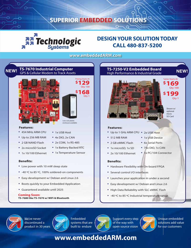
We’ve never
discontinued a
product in 30 years
Embedded
systems that are
built to endure
Unique embedded
solutions add value
for our customers
Support every step
of the way with
open source vision
Sup
of th
opeOPEN
Emb
syst
builRUG
GEDWe’v
disc
prodLON
G L
IFE Uniq
solu
for oORIG
INAL
DESIGN YOUR SOLUTION TODAY
CALL 480-837-5200
www.embeddedARM.com
129$
Qty 1168
Pricing Starts At
Qty 100
$
TS-7670 Industrial ComputerGPS & Cellular Modem to Track Assets
TS-7250-V2 Embedded BoardHigh Performance & Industrial Grade
Qty 1
199
169$
$
Series Starts At
Qty 100
Guaranteed available until 2025
Easy development w/ Debian and Linux 2.6
Boots quickly to your Embedded Application
Low power with 10 mW sleep state
Coming Soon:
TS-7680 like TS-7670 w/ WiFi & Bluetooth
Benefits:
-40 ºC to 85 ºC, 100% soldered-on components
454 MHz ARM CPU
Up to 256 MB RAM
1x USB Host
4x DIO, 2x CAN
2x microSD Socket
2 GB NAND Flash
1x Battery Backed RTC
2x COM, 1x RS-485
1x 10/100 Ethernet 1x Temperature Sensor
Features:
$
$
Se
Shown w/
optional
micro
SD Card
-40 ºC to 85 ºC Industrial temperature range
Easy development w/ Debian and Linux 2.6
High Data Reliability with SLC eMMC Flash
Several control I/O interfaces
Hardware Flexibility with On-board FPGA
Benefits:
Launches your application in under a second
Up to 1 GHz ARM CPU
512 MB RAM
2x USB Host
1x USB Device
1x microSD, 1x SD
2 GB eMMC Flash
75x DIO, 1x CAN
6x Serial Ports
2x 10/100 Ethernet 1x PC/104 Connector
Features:
Low cost plastic
enclosure available

locate, communicate, accelerate
LTE category 4: 150 Mb/s download, 50 Mb/s upload
Layout-compatible with u-blox 2G, 3G & CDMA modules
Variants for America, Europe and Asia; supports VoLTE
Seamless interface to u-blox GNSS & CellLocate® indoor positioning
LGA and Mini PCIe packages
Industry’s smallest LTE/HSPA+/GPRS modules
TOBY-L2 series High-speed LTE multimode modules
www.u-blox.com
TOBY-L2 series24.8 x 35.6 x 2.6 mm