new versafitcup cc trio - medacta · 2017. 3. 7. · versafitcup ® cc trio surgical technique 6...
TRANSCRIPT

Hip Knee Spine Navigation
Surgical Technique
each to the i r owN
V E R S A F I T C U P® C C T R I O

Versafitcup® CC TRIO Surgical Technique
2
Hip Knee Spine Navigation
The Versafitcup® CC Trio is a range of press-fit acetabular shell which offers different solutions according to patient needs: flat and hooded liners in standard UHMWPE or Highcross® cross-linked Polyethylene; possibility to be supported or not by screws.
e a c h t o t h e i r o w N
This document describes the Surgical Technique for Versafitcup® CC Trio.
Carefully read the instructions for use and if you have any questions concerning product compatibility please contact your Medacta® representative.
P r e a M B L e
Federal law (USA) restricts this device to sale distribution and use by or on the order of physician.
c a U t i o N
3
1 iNdicatioNS 4
2 coNtraiNdicatioNS 4
3 PreoPerative PLaNNiNg 4
4 SUrgicaL aPProach 4
5 reaMiNg 5
6 triaLS 6
7 iMPactioN oF the acetaBULar SheLL 7
8 StaBiLitY teSt 9
9 PoSitioNiNg oF deFiNitive LiNer 10
10 iMPLaNtS NoMeNcLatUre 11
i N d e X

Versafitcup® CC TRIO Surgical Technique
4
Hip Knee Spine Navigation
1 iNdicatioNSthe versafitcup cc trio is designed for cementless use in total hip arthroplasty in primary or revision surgery. the patient should be skeletally mature. the patient's condition should be due to one or more of:
Severely painful and/or disabled joint: as a result of osteoarthritis, post-traumatic arthritis, rheumatoid arthritis or psoriactic arthritis, congenital hip dysplasia, ankylosing spondylitis
avascular necrosis of the femoral head
acute traumatic fracture of the femoral head or neck
Failure of previous hip surgery: joint reconstruction, internal fixation, arthrodesis, hemiarthroplasty, surface replacement arthroplasty, or total hip replacement where sufficient bone stock is present
2 coNtraiNdicatioNStotal or partial hip replacement is contraindicated in the following cases:
acute, systemic or chronic infection
Muscular, neurological or vascular deficiency of the affected limb
Bone destruction, or loss of bone characteristics that may compromise the stability of the implant
Pathologies that may compromise the functionality of the implant in any way
Mental or neuromuscular disorders may create an unacceptable risk to the patient and can be a source of postoperative complications. it is the surgeon’s responsibility to ensure that the patient has no known allergy to the materials used.
3 PreoPerative PLaNNiNgthe goal is to determine the optimum acetabular implant size. Using the set of X-ray templates to the scale of 1.15:1 (with an X-ray of the same magnification) it will be possible to determine:
the implant size
the ideal position of the acetabular shell for optimum coverage.
NOTICEthe final implant will be selected intra-operatively, because of possible discrepancies between actual conditions and templating.
SUrgicaL aPProachthe choice of surgical approach is up to the surgeon.
4
5
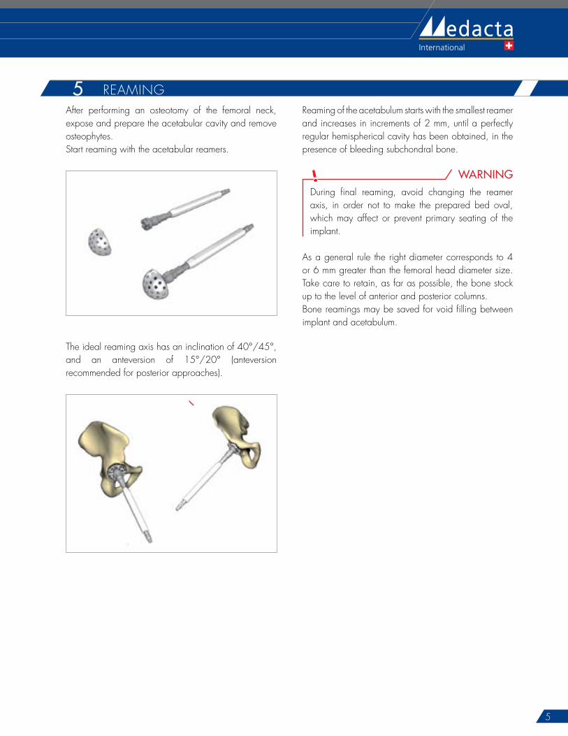
after performing an osteotomy of the femoral neck, expose and prepare the acetabular cavity and remove osteophytes.Start reaming with the acetabular reamers.
the ideal reaming axis has an inclination of 40°/45°, and an anteversion of 15°/20° (anteversion recommended for posterior approaches).
40°- 45°
15°- 20°
reaming of the acetabulum starts with the smallest reamer and increases in increments of 2 mm, until a perfectly regular hemispherical cavity has been obtained, in the presence of bleeding subchondral bone.
WARNINGduring final reaming, avoid changing the reamer axis, in order not to make the prepared bed oval, which may affect or prevent primary seating of the implant.
as a general rule the right diameter corresponds to 4 or 6 mm greater than the femoral head diameter size. take care to retain, as far as possible, the bone stock up to the level of anterior and posterior columns.Bone reamings may be saved for void filling between implant and acetabulum.
5 reaMiNg

Versafitcup® CC TRIO Surgical Technique
6
Hip Knee Spine Navigation
6Both implant and trial cup have a 5° raise. Marks on the trial cup and on the acetabular shell help to identify coverage top (see image).
5° 5°
=
coverage top
Marks on the trial cup
Marks on the acetabular shell
raise raise5° 5°
=
coverage top
Marks on the trial cup
Marks on the acetabular shell
raise raise
OPTIONin order to ensure the correct positioning of the definitive acetabular shell, use electrocautery to mark the coverage top.
NOTICEif the trial cup is not stable or primary stability is doubtful, especially in the presence of poor bone quality, it is possible to choose a larger cup size, either with or without additional acetabular reaming.
assemble the trial cup with the same diameter of the last reamer onto the multifunction handle.insert the trial cup into the reamed cavity in order to estimate the depth and the orientation of the acetabular component.
Trial cups:
are smooth and have the same dimensions as the reamers to avoid damaging the socket
are slightly undersized compared to the implant to allow a maximum press-fit effect with the definitive implant
have several openings to permit a direct view of the underlying acetabular surface.
Both reamers and trial cups are hemispherical, whereas the implants are elliptical and equatorially expanded, providing a good initial press-fit.
triaLS

7
Never use the impactor handle after the impaction to reposition or rotate the acetabular shell, in order not to damage the threaded end. if needed, use only the acetabular shell correction impactor, assembled with the multifunction handle. impact the acetabular shell with the aid of a hammer, until it is completely stable.remove the impactor handle.
CAUTIONafter impaction of the acetabular shell, ensure osteophytes have been properly removed in order to avoid any impingement.
TRICKin order to ensure the correct depth of the definitive acetabular shell, use the mark made during the test with the trial cup or use the holes to see the acetabulum floor. Because of the elliptical shape of the acetabular shell, it is normal to have a space between acetabular shell and acetabulum floor. this distance should be no deeper than 2 mm.
7after a satisfactory trial, the final acetabular shell can be positioned. the definitive acetabular shell size will be the same as the final trial cup size. however the acetabular shell is slightly oversized in order to allow a maximum press-fit. assemble the impactor handle with the acetabular shell until it is completely locked, in order not to damage the impactor screw thread during the impaction. impact the implant at the desired angle of orientation into the prepared acetabulum.
5° 12h00Coverage top at 12h00
OPTIONan orientation guide is available to aid in the acetabular shell positioning and to find satisfactory orientation tested during trials: the orientation guide will be positioned on the top of the impactor handle. the two rods are inclined at 45° and 20° to the handle.
iMPactioN oF the acetaBULar SheLL

Versafitcup® CC TRIO Surgical Technique
8
Hip Knee Spine Navigation
in case of instability of the trial cup or any doubt of its primary stability, it is possible to add intra acetabular screws.drill through the acetabular shell holes using a Ø 3.2 mm drill bit with the help of a drill guide. Use the hooked depth gauge in order to measure the drilling depth and select a self-tapping screw of appropriate length (with flat head and Ø 6.5 mm).Screwing is performed with the aid of a universal hex-head screwdriver.
CAUTIONalways use flat head screws and check that the screws are fully seated (ensure that the screw heads do not protrude from the inner surface of the acetabular shell).the maximum screw angle allowed round the radial positioning is 10 degrees.
NOTICEit is possible to close the central hole with a metallic plug, which is packed together with the acetabular shell.

9
during stability tests, the choice between a flat and a hooded liner can be made according to the surgeon’s choice.
clean the interior surface of the acetabular shell.assemble the multifunction handle with the trial liner corresponding to the acetabular shell size and femoral head diameter (liners with interior diameter of 36 mm are available only for flat UhMwPe highcross® versions).Position the assembly in the acetabular shell.Unscrew the multifunction handle and reduce the hip in order to test the joint stability and limb length.after checking and testing mobility, joint stability and lower limb length, remove the trial liner with the aid of the multifunction handle.
StaBiL itY teSt8TRICK
in case of hooded trial liner, use electrocautery to mark the satisfactory position of the hood.
WARNINGtests of stability must be performed with trial heads and not with definitive heads. the head sizes XL (for Ø 28 mm, Ø 32 mm) and XXL (for Ø 28 mm, Ø 32 mm, Ø 36 mm) have a collar. this may decrease the range of Motion in comparison to smaller sizes. always perform trial reduction with the chosen head size.
Versafitcup® CC TRIO Surgical Technique
10
Hip Knee Spine Navigation
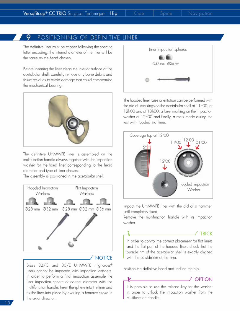
the definitve liner must be chosen following the specific letter encoding; the internal diameter of the liner will be the same as the head chosen.
Before inserting the liner clean the interior surface of the acetabular shell, carefully remove any bone debris and tissue residues to avoid damage that could compromise the mechanical bearing.
the definitive UhMwPe liner is assembled on the multifunction handle always together with the impaction washer for the fixed liner corresponding to the head diameter and type of liner chosen.the assembly is positioned in the acetabular shell.
hooded impaction washers
Flat impaction washers
Ø28 mm Ø32 mm Ø28 mm Ø32 mm Ø36 mm
NOTICE
Sizes 32/c and 36/e UhMwPe highcross® liners cannot be impacted with impaction washers. in order to perform a final impaction assemble the liner impaction sphere of correct diameter with the multifunction handle. insert the sphere into the liner and fix the liner into place by exerting a hammer stroke in the axial direction.
the hooded liner raise orientation can be performed with the aid of: markings on the acetabular shell at 11h00, at 12h00 and at 13h00, a laser marking on the impaction washer at 12h00 and finally, a mark made during the test with hooded trial liner.
5°
12h00coverage top at 12h00
11h00
12h00
hooded impaction washer
01h00
impact the UhMwPe liner with the aid of a hammer, until completely fixed.remove the multifunction handle with its impaction washer.
TRICKin order to control the correct placement for flat liners and the flat part of the hooded liner: check that the outside rim of the acetabular shell is exactly aligned with the outside rim of the liner.
Position the definitive head and reduce the hip.
OPTIONit is possible to use the release key for the washer in order to unlock the impaction washer from the multifunction handle.
Liner impaction spheres
Ø32 mm Ø36 mm
9 PoSitioNiNg oF deFiNitive L iNer

11
verSaFitcUP® cc trio acetaBULar SheLL
diameter (mm) ref. Liner Size46 01.26.45.0046 c48 01.26.45.0048 c50 01.26.45.0050 e52 01.26.45.0052 e54 01.26.45.0054 e56 01.26.45.0056 F58 01.26.45.0058 F60 01.26.45.0060 F62 01.26.45.0062 g64 01.26.45.0064 g
acetaBULar SheLL ceNtraL PLUg
description ref.Plug 01.26.45.0070
UhMwPe FLat LiNer
Liner size c e F g
headØ 28 01.26.2839Stt 01.26.2844Stt 01.26.2848Stt 01.26.2852SttØ 32 - 01.26.3244Stt 01.26.3248Stt 01.26.3252Stt
UhMwPe hooded LiNer
Liner size c e F g
headØ 28 01.26.2839at 01.26.2844at 01.26.2848at 01.26.2852atØ 32 - 01.26.3244at 01.26.3248at 01.26.3252at
hooded UhMwPe hc LiNer (highcross®)
Liner size c e F g
headØ 28 01.26.2839hcat 01.26.2844hcat 01.26.2848hcat 01.26.2852hcatØ 32 - 01.26.3244hcat 01.26.3248hcat 01.26.3252hcat
FLat UhMwPe hc LiNer (highcross®)
Liner size c e F g
headØ 28 01.26.2839hct 01.26.2844hct 01.26.2848hct 01.26.2852hctØ 32 01.26.3239hct 01.26.3244hct 01.26.3248hct 01.26.3252hctØ 36 - 01.26.3644hct 01.26.3648hct 01.26.3652hct
Note for sterilization: the instruments are not sterile upon delivery. instruments must be cleaned before use and sterilized in an autoclave respecting the US regulations, directives where applicable, and following the manufactures instructions for use of the autoclave. For detailed instructions please refer to the document “recommendations for cleaning decontamination and sterilization of Medacta® international reusable orthopaedic devices” available at www.medacta.com. versafitcup®, highcross® and Medacta® are registered trademarks of Medacta® international Sa, castel San Pietro, Switzerland.
N o t e F o r S t e r i L i Z a t i o N
caNceLLoUS BoNe Screw (FLat head - Ø 6.5 mm)
Length (mm) ref.20 01.26.65.2025 01.26.65.2530 01.26.65.3035 01.26.65.3540 01.26.65.4045 01.26.65.45
Part numbers subject to change.
iMPLaNtS NoMeNcLatUre10

d i S t r i B U t e d B Y
Medacta International SA Strada regina - 6874 castel San PietroSwitzerlandPhone +41 91 696 60 60 Fax +41 91 696 60 [email protected]
Medacta USA4725 calle Quetzal Suite B - camarillo california 93012Phone +1 805 437 7085Fax +1 805 437 [email protected]
versafitcup® cc trioSurgical techniqueref: 99.16trio.12USrev. 03
V E R S A F I T C U P® C C T R I O