new york city college of...
TRANSCRIPT
D. Mynbaev TCET 4102,Module 8,Spring 2008 1
NEW YORK CITY COLLEGE of TECHNOLOGYTHE CITY UNIVERSITY OF NEW YORK
DEPARTMENT OF ELECTRICAL AND TELECOMMUNICATIONS
ENGINEERING TECHNOLOGY
Course : TCET 4102 Fiber-optic communicationsModule 8: Introduction to optical networks
Prepared by: Professor Djafar K. MynbaevSpring 2008
D. Mynbaev TCET 4102,Module 8,Spring 2008 2
• Receiver – review
• Introduction to optical networks
• Point-to-point link
• Network
• Physical topologies
• Logical topologies
• Telecommunications networks –physical and logical levels
• Switching
• Circuit switching and packet switching
• Control plane and data plane
Textbook: Djafar K. Mynbaev and Lowell L. Scheiner, Fiber-Optic Communications Technology, Prentice Hall, 2001, ISBN 0-13-962069-9.
Notes:
The figure numbers in these modules are the same as in the textbook. New figures are not numbered.
Always see examples in the textbook
Key words
• Point-to-point link
• Network
• Physical topologies
• Logical topologies
• Physical level
• Logical (intelligent) level
• Switching
• Circuit switching and packet switching
• Control plane and data plane
Module 8: Introduction to optical
networks
D. Mynbaev TCET 4102,Module 8,Spring 2008 3
Receiver - review
Electronics
Light source (Laser diode, LD)
Photodiode (PD)Transmitter (Tx)
Receiver (Rx)
Optical fiber
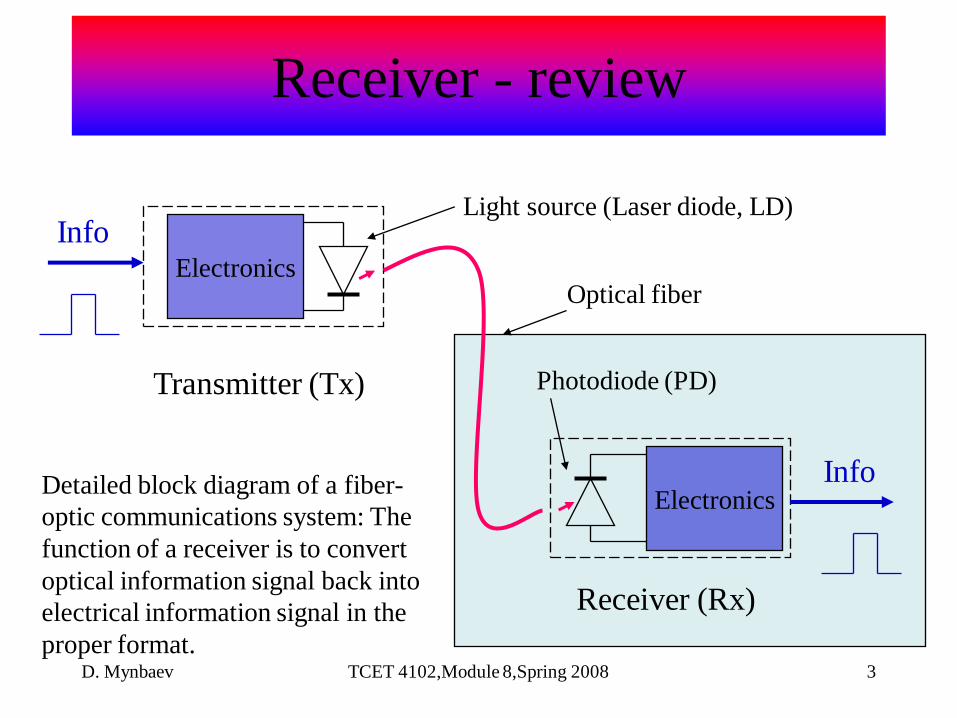
Detailed block diagram of a fiber-
optic communications system: The
function of a receiver is to convert
optical information signal back into
electrical information signal in the
proper format.
Info
InfoElectronics
D. Mynbaev TCET 4102,Module 8,Spring 2008 4
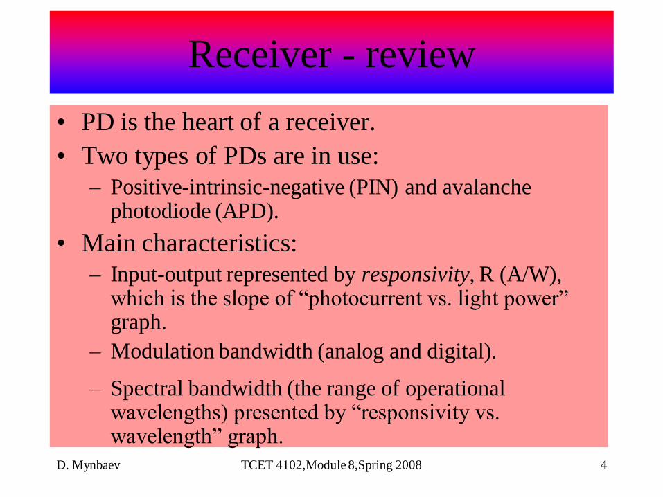
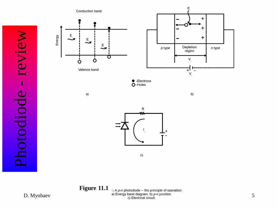
• PD is the heart of a receiver.
• Two types of PDs are in use:
– Positive-intrinsic-negative (PIN) and avalanche photodiode (APD).
• Main characteristics:
– Input-output represented by responsivity, R (A/W), which is the slope of ―photocurrent vs. light power‖ graph.
– Modulation bandwidth (analog and digital).
– Spectral bandwidth (the range of operational wavelengths) presented by ―responsivity vs. wavelength‖ graph.
Receiver - review
D. Mynbaev TCET 4102,Module 8,Spring 2008 5
Photo
dio
de
-re
vie
w
Figure 11.1

D. Mynbaev TCET 4102,Module 8,Spring 2008 6
Photo
dio
de
-re
vie
w
Figure 11.1
D. Mynbaev TCET 4102,Module 8,Spring 2008 7
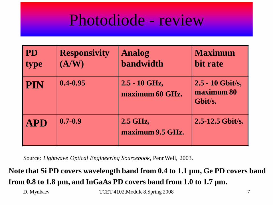
Source: Lightwave Optical Engineering Sourcebook, PennWell, 2003.
Note that Si PD covers wavelength band from 0.4 to 1.1 µm, Ge PD covers band
from 0.8 to 1.8 µm, and InGaAs PD covers band from 1.0 to 1.7 µm.
PD
type
Responsivity
(A/W)
Analog
bandwidth
Maximum
bit rate
PIN 0.4-0.95 2.5 - 10 GHz,
maximum 60 GHz.
2.5 - 10 Gbit/s,
maximum 80
Gbit/s.
APD 0.7-0.9 2.5 GHz,
maximum 9.5 GHz.
2.5-12.5 Gbit/s.
Photodiode - review

D. Mynbaev TCET 4102,Module 8,Spring 2008 8
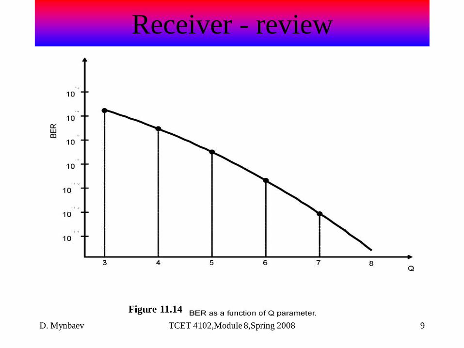
• Important characteristics of a receiver:
– Bit-error rate (BER)—ratio of the number of erroneous
bits to the total number of bits transmitted. BER
depends on digital SNR, Q. Typical value of BER is
10-9; modern optical networks operate at BER 10-12.
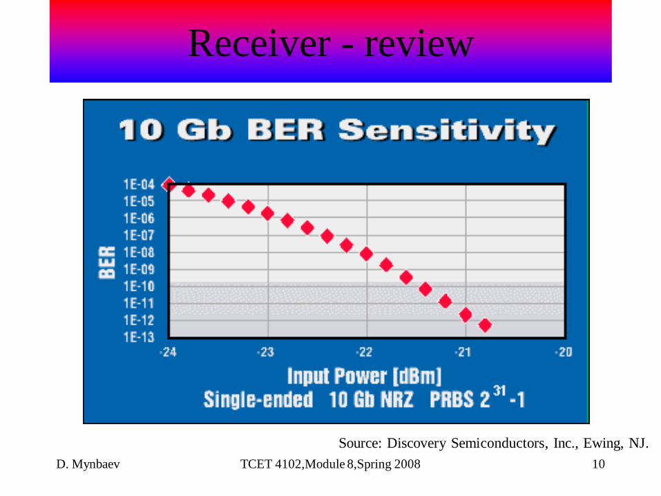
– Receiver sensitivity—minimum received power
required to provide the given BER. Typical values of
PD sensitivity vary from –15 dBm to –50 dBm,
depending on the bit rate.
Receiver - review
D. Mynbaev TCET 4102,Module 8,Spring 2008 9
Receiver - review
Figure 11.14
D. Mynbaev TCET 4102,Module 8,Spring 2008 10
Source: Discovery Semiconductors, Inc., Ewing, NJ.
Receiver - review
D. Mynbaev TCET 4102,Module 8,Spring 2008 11
Optical networks - introduction
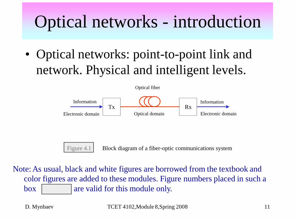
• Optical networks: point-to-point link and
network. Physical and intelligent levels.
Tx RxInformation Information
Electronic domain Electronic domainOptical domain
Optical fiber
Figure 4.1 Block diagram of a fiber-optic communications system
Note: As usual, black and white figures are borrowed from the textbook and
color figures are added to these modules. Figure numbers placed in such a
box are valid for this module only.
D. Mynbaev TCET 4102,Module 8,Spring 2008 12
Optical networks - introduction

D. Mynbaev TCET 4102,Module 8,Spring 2008 13
• Telecommunications system shown in Figure 4.1 is called pint-to-point link. This system, indeed, provides connection between two points only. This is a building block of any sophisticated telecommunications infrastructure. However, such a block is not enough to build telecommunications network.
• In general, telecommunications network provides exchanging information among many users. Think about PSTN: While you are talking over the phone with your calling part, millions of others also talk over the phones. PSTN supports all these telephone conversations regardless the locations of all the parties and time of their calls. How is it possible? This is because PSTN is a network, not just a point-to-point link. What is network?
• A network is a set of nodes connected by links.
• A node is any lumped element, such as computer, switch, telephone, printer, router, repeater, etc. Links are means of contact between nodes; they are made of various media, such as copper wire, coaxial cable, air for electromagnetic waves, and optical fiber.
• This very general definition stresses the main feature of a network: It consists of nodes and links. The above definition of network emphasizes the physical layout through which signals can be transmitted. This definition can be applied to any type of connections such as electrical circuit, electrical power grid, transport network, etc. However, in telecommunications we need to deliver information; therefore, telecommunications network must be able to transmit information signals. Let’s consider one example to stress this network ability.
Optical networks - introduction

D. Mynbaev TCET 4102,Module 8,Spring 2008 14
Optical networks - introduction
Node 1
Node 2
Node 3
Node 5
Node 4
Node N
Figure 4.2 Network.
InternetInternet
1
2
3
―Can I send you the first packet of my message?‖
―Yes, you can send up to 65 kbit.‖
―I received the first packet;
now you can send the second
up to 65 kbit.‖
Figure 4.3 Communications between two computers
through the Internet.
Yours
computerYour
friend’s
computer

D. Mynbaev TCET 4102,Module 8,Spring 2008 15
• Telecommunications network: physical and logical (intelligent) sides Suppose you send e-mail message to your friend. Technically it means that your computers communicate through the Internet. How this communications occur? First, both computers must be physically connected one with other. This is what physical layout shown in Figure 4.2 is about. If your computer is Node 3 and your friend computer is Node 5, both computers are connected through Node 1. However, these two computers can (and they really do) exchange signals through Nodes 2, 4, and many others. We usually symbolize all the Internet connections as a cloud; Figure 4.3 shows this symbol.
• After your computers establish connections, they start to exchange messages. In a very oversimplified form, this exchange occurs as follows: Yours (sending) computer ―asks‖ the recipient (your friend’s computer) whether it is ready to accept a new message. The receiving computer informs the sending computer that (1) yes, it can accept data but (2) since its capacity is always restricted, the receiver can accept up to certain number of bits at once. This restriction is the key feature in prevention a receiver from overwhelming with the incoming flow of information. After accepting the first portion (packet) of information, the receiving computer acknowledges that and informs the transmitting computer that it is ready for the second portion of a message. The receiving computer again informs the transmitter that it is capable to accept only the certain number of bits at once. This exchange information continues until transmission of the entire message (your e-mail) is completed. Figure 4.3 illustrates these explanations.
Optical networks - introduction
D. Mynbaev TCET 4102,Module 8,Spring 2008 16
• You certainly noticed that communicating computers not simply sending and receiving information but also exchange by the servicemessages. Can they communicate without these auxiliary messages? No! They must follow the certain rules and these service messages enforce these rules. Indeed, imagine that your computer sends your e-mail as a simple stream of bits without communicating with a receiving computer. First, the receiver might be busy and you e-mail would go nowhere. Secondly, the receiver could be overwhelmed with the first portion of your e-mail and never accepts the rest. And don’t forget: We’ve reduced the actual transmission to two simple steps; in reality, transmitting information through the Internet is much more sophisticated process.
• In spite of oversimplification, this example emphasizes two main features of a telecommunications network: First, the network must provide physical connections among all communicating parties; secondly, communication is possible if and only if the communicating parties follow the certain rules (protocols). But connections are something physical, tangible while protocols are something logical, intelligent. Therefore,
• telecommunications network are built on two aspects (sides): physical and logical (intelligent).
• Clearly, physical side is given by the network’s physical facilities such as transmitters, receivers, switches, links, etc. What devices support logical (intelligent) work? The general answer is, computers. Specifically, we refer to electronic machines that are able to perform arithmetic and logic operations, such as processors.
• These processors not only support logical operations at the end nodes to analyze the content of the sending and arriving messages; they also control another type of operation without which telecommunications network cannot exist—switching. Look at Figure 4.2 again: To direct your message from Node 3 to Node 5 through Node 1, for example, these nodes must ―know‖ the route: Node 3 must know that message is to be send to Node 1 and Node 1 must know that it has to switch the message to Node 5, not to Node 4. Thus, the processor at Node 1 commands its switch to route your message (portion, or packet, of this message, remember?) to Node 5. What if the nodes of a telecommunications network would not be able to perform switching? There would be no network, just a set of point-to-point links. Therefore,
• switching (routing) ability is the main feature of a logical (intelligent) aspect of a telecommunications network.
• A word about terminology: Switching is a general term that refers to operation of relaying messages through a network. However, in telecommunications we use term switching to describe transferring signals from one circuit to another; in other words, switching refers to circuit-to-circuit connections within a network. Routing is also a general term that refers to switching among networks; however, in regards to the Internet communications, routing means forwarding packets through network.
• To emphasize the critical role of intelligent aspect in operations of telecommunications networks, we use to say that physical layout provides the raw bandwidth while the real pace of information flow is determined by both physical and intelligent sides of networks.
• From discussion of this simple example we can conclude that telecommunications network cannot exist without both--physical and logical--sides.
Optical networks - introduction

D. Mynbaev TCET 4102,Module 8,Spring 2008 17
• Importance of intelligent side of telecommunications networks: The flow control bottleneck Back to the mainstream of our discussion, it seems that the most important point about telecommunications network is the physical layout. Indeed, we’ve stressed already that telecommunications industry experienced revolutionary changes with the advent of optical communications, which means using optical fiber and photonic equipment to provide telecommunication. In other words, this revolution has been caused by the physical side of telecommunications networks. Indeed, placing the nodes and connecting them by links are the necessary conditions for building telecommunications networks. However, to make telecommunications networks operate we need to provide them with some intelligence, the ability to perform logical operations. And this intelligence is the sufficient conditions for building telecommunications networks. Let’s consider one example to show that both necessary and sufficient conditions must be met in telecommunications networks.
• The Transmission Control Protocol (TCP) along with Internet Protocol (IP) runs all communications on the Internet. Both protocols are the stocks of rules that control logical operation in the Internet communications. One of the TCP features is the flow control that prevents a receiver from overwhelming. In its original form, TCP specifies the number of bits that a receiver can accept at once. As we’ve discussed in our example of computer communications regarding Figure 4.3, this specification is implemented by making areceiver ―tell‖ a sender how many bits it can accept. This number of bits is called flow control window size; in its original TCP specification it was equal to 524,280 bits, or 65,535 bytes.
• Let’s turn again to Figure 1.6-2 to analyze the timing in computer communications: The transmitting computer sends packet—whose size is equal to a flow control window—to a receiver and a receiver sends back acknowledgment. Thus, the duration of every cycle of this communications is equal to round-trip time between two computers. The number of bits transmitting for that time is equal to window size plus acknowledgement whose size is negligible. Therefore, the bit rate, which is a number of bits per second, is equal to [5]
• Bit rate = Window size/Round-trip time
• Round-trip time on the Internet varies tremendously; however, 100 ms is a reasonable average number for the Internet communications within the United States. Thus, taking original TCP window size equal to 524,280 bits and dividing them by 100 ms, we obtain
• Bit rate = 524,280 bits/100 ms = 524,280 bits/0.1 s
• = 5,242,800 bit/s = 5.2428 Mbit/s
• Therefore, the flow control—the logical aspect of the network operation—restricts the bit rate to about 5 Mbit/s. At the same time, theoretical transmission capacity of optical fiber is more than 50 Tbit/s.
• Thus, optical fiber can deliver 10 million times faster than flow control allows!
• In other words, in our example this is a logical (intelligent) side of telecommunications networks, not their physical side, which limits their transmission capacity.
• To emphasize the critical role of intelligent aspect in operations of telecommunications networks, we use to say that physical layout provides the raw bandwidth while the real pace of information flow is determined by both physical and intelligent sides of networks.
• From discussion of this simple example we can conclude that telecommunications network cannot exist without both--physical and logical--sides.
Optical networks - introduction

D. Mynbaev TCET 4102,Module 8,Spring 2008 18
Optical networks - introduction

D. Mynbaev TCET 4102,Module 8,Spring 2008 19
• Optical networks – physical topologies:
Figure 1.2 visualizes several network physical topologies (configurations or layouts). Physical topology shows how nodes are connected with each other. In contrast, logical topology shows how information flows through the network. And information can flow by different ways over the network with the same physical topology. For example, it is possible to arrange ring logical topology over the star physical layout. This is why we have to distinguish between physical and logical topologies.
Main feature of a telecommunications network is switching; that is, the re-directing signals from one path to another to deliver a message to any user of the network.
Optical networks - introduction
D. Mynbaev TCET 4102,Module 8,Spring 2008 20
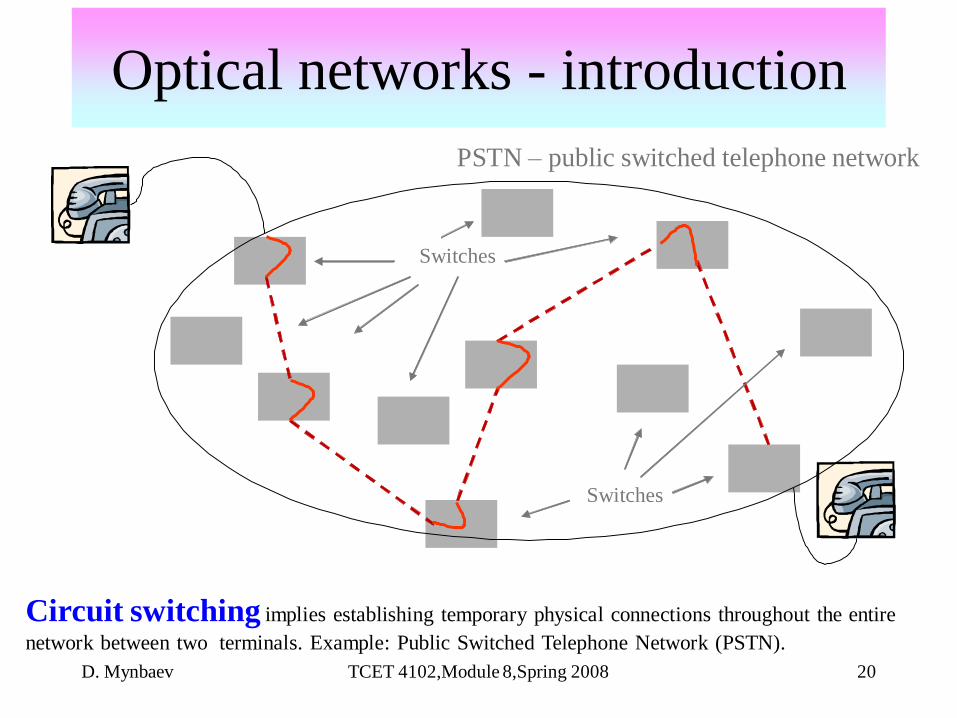
Optical networks - introduction
Switches
Switches
Circuit switching implies establishing temporary physical connections throughout the entire
network between two terminals. Example: Public Switched Telephone Network (PSTN).
PSTN – public switched telephone network

D. Mynbaev TCET 4102,Module 8,Spring 2008 21
Optical networks -
introductionOverview of optical networks--
Packet switching: block diagram
Packet switching
Internet
Switch
Packet switching implies breaking a message into a set of small packets and sending these packets through
a network by different routes. At the destination, these packets are assembled back into the original
message. No special connections are established for a specific transmission through the network.
Example: the Internet.

D. Mynbaev TCET 4102,Module 8,Spring 2008 22
Data packets
Optical (fiber/lambda)
circuit switching
Optical
packet switching
Electronic
packet switching
O/E
conversion
Data packets
Internet
As optical communications has migrated from point-to-point links to optical networks, switching and routing
problems ideal solution: optical packet switching .
Optical networks – IP over WDM
D. Mynbaev TCET 4102,Module 8,Spring 2008 23
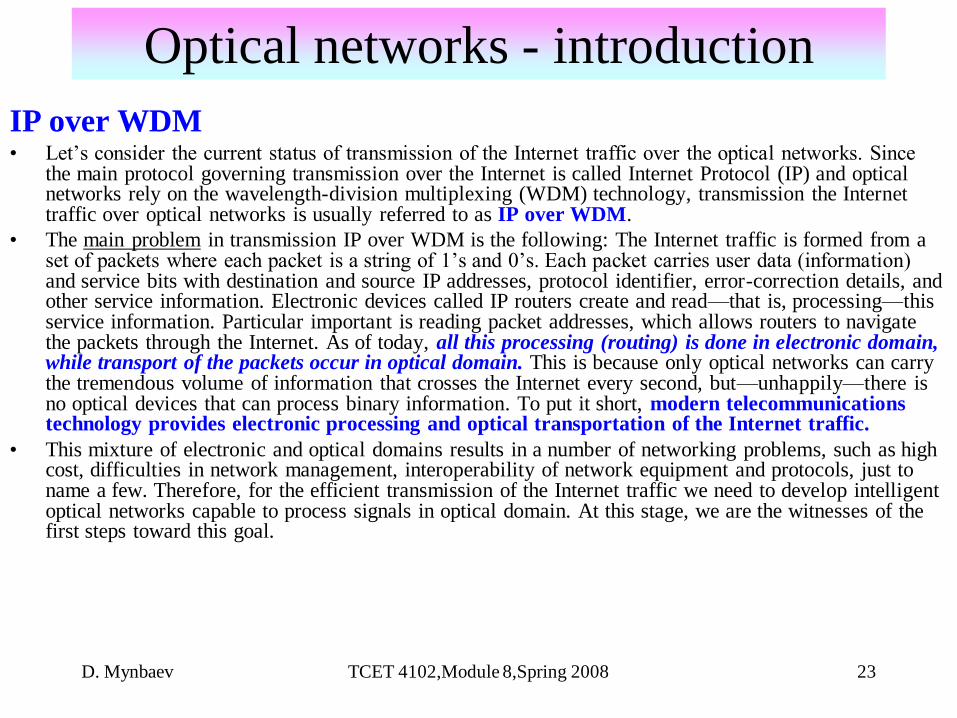
IP over WDM• Let’s consider the current status of transmission of the Internet traffic over the optical networks. Since
the main protocol governing transmission over the Internet is called Internet Protocol (IP) and optical networks rely on the wavelength-division multiplexing (WDM) technology, transmission the Internet traffic over optical networks is usually referred to as IP over WDM.
• The main problem in transmission IP over WDM is the following: The Internet traffic is formed from a set of packets where each packet is a string of 1’s and 0’s. Each packet carries user data (information) and service bits with destination and source IP addresses, protocol identifier, error-correction details, and other service information. Electronic devices called IP routers create and read—that is, processing—this service information. Particular important is reading packet addresses, which allows routers to navigate the packets through the Internet. As of today, all this processing (routing) is done in electronic domain, while transport of the packets occur in optical domain. This is because only optical networks can carry the tremendous volume of information that crosses the Internet every second, but—unhappily—there is no optical devices that can process binary information. To put it short, modern telecommunications technology provides electronic processing and optical transportation of the Internet traffic.
• This mixture of electronic and optical domains results in a number of networking problems, such as high cost, difficulties in network management, interoperability of network equipment and protocols, just to name a few. Therefore, for the efficient transmission of the Internet traffic we need to develop intelligent optical networks capable to process signals in optical domain. At this stage, we are the witnesses of the first steps toward this goal.
Optical networks - introduction

D. Mynbaev TCET 4102,Module 8,Spring 2008 24
Optical networks - introduction
Control plane and data plane: Separation of control and transport functions
Data plane
(OXC)
Control plane
(router)
Control
messages
Control
messages
TrafficTraffic
Interface
Optical network node
Control plane and data (forwarding) plane: Several cornerstone steps have been made in this
direction. First, the well-known concept of separation transport and control of transportation was
introduced into optical domain. This introduction was made in from of separation of control and
data planes at every network node. These planes are shown in Figure 5-1.
Figure 5-1 Control plane and data plane of an optical network node.
D. Mynbaev TCET 4102,Module 8,Spring 2008 25
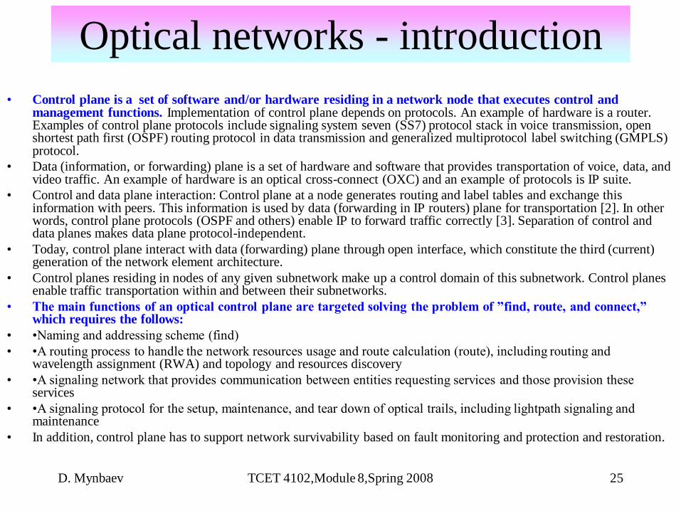
• Control plane is a set of software and/or hardware residing in a network node that executes control and management functions. Implementation of control plane depends on protocols. An example of hardware is a router. Examples of control plane protocols include signaling system seven (SS7) protocol stack in voice transmission, open shortest path first (OSPF) routing protocol in data transmission and generalized multiprotocol label switching (GMPLS) protocol.
• Data (information, or forwarding) plane is a set of hardware and software that provides transportation of voice, data, and video traffic. An example of hardware is an optical cross-connect (OXC) and an example of protocols is IP suite.
• Control and data plane interaction: Control plane at a node generates routing and label tables and exchange this information with peers. This information is used by data (forwarding in IP routers) plane for transportation [2]. In other words, control plane protocols (OSPF and others) enable IP to forward traffic correctly [3]. Separation of control and data planes makes data plane protocol-independent.
• Today, control plane interact with data (forwarding) plane through open interface, which constitute the third (current) generation of the network element architecture.
• Control planes residing in nodes of any given subnetwork make up a control domain of this subnetwork. Control planes enable traffic transportation within and between their subnetworks.
• The main functions of an optical control plane are targeted solving the problem of ”find, route, and connect,” which requires the follows:
• •Naming and addressing scheme (find)
• •A routing process to handle the network resources usage and route calculation (route), including routing and wavelength assignment (RWA) and topology and resources discovery
• •A signaling network that provides communication between entities requesting services and those provision these services
• •A signaling protocol for the setup, maintenance, and tear down of optical trails, including lightpath signaling and maintenance
• In addition, control plane has to support network survivability based on fault monitoring and protection and restoration.
Optical networks - introduction
D. Mynbaev TCET 4102,Module 8,Spring 2008 26
Optical networks - introduction
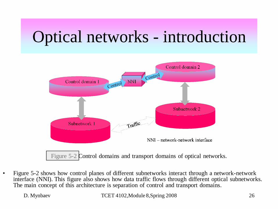
Figure 5-2 Control domains and transport domains of optical networks.
• Figure 5-2 shows how control planes of different subnetworks interact through a network-network interface (NNI). This figure also shows how data traffic flows through different optical subnetworks. The main concept of this architecture is separation of control and transport domains.

D. Mynbaev TCET 4102,Module 8,Spring 2008 27
• How the concept of control plane helps in transmission of the Internet traffic over optical networks? Figure 5-3 visualizes the idea of this transmission:
• IP edge router requests a service (for instance, a label switched path connection) from an adjacent OTN router.
• An optical network interconnects its core nodes to provide the requested service but doesn’t inform IP network. Thus, OTN offers high-bandwidth connectivity in the form of lightpaths.
• No routing or other type of information from the optical network is available to the IP networks; that is, OTN (service provider) is opaque to the IP network (service requester).
• Therefore, label attached to a packet by an edge IP router is the only service information presented to an optical networks. Through label switching, processing of service information is done in optical domain. Generalized Multiprotocol Label Switching (GMPLS) protocol suite supports this operation. Figure 5-3 illustrates this idea.
Optical networks - introduction

D. Mynbaev TCET 4102,Module 8,Spring 2008 28
Optical networks - introduction
OXC
OXC
Optical transport network (OTN)
IP router = label-
switched router
(LSR)
UNI
UNI
LightpathData traffic
Two separate control planes: One in OTN and the other in the LSRs.
Advantage: It is easily to deploy since transport and clients are
independent. Disadvantage: data and control traffic are combined
limited number of LSRs can participate in the network [4].
IP router = label-
switched router (LSR)
Control traffic
UNI – user-network interface; OXC – optical cross-connect (switch)
Figure 5-3 Transmission IP traffic over the optical transport network.

D. Mynbaev TCET 4102,Module 8,Spring 2008 29
Optical networks - introductionControl plane and data plane (continued)

D. Mynbaev TCET 4102,Module 8,Spring 2008 30
• In conclusion, we need to stress where optical networks were yesterday and where they are today:
• Initially optical fibers were used as pipes to transport large volume of traffic while all processing (intelligent) work was relegated to electronics. Thus, multiplexing, switching and routing were done in electronic domain. Optical transport was simply the sets of point-to-point links.
• Today optical networks have reached the point where the need arise for execution of all transport tasks in optical domain.
• Now we are in the transition stage.
• This is the trend to watch in the development of optical networks.
Optical networks - introduction

D. Mynbaev TCET 4102,Module 8,Spring 2008 31
References:
1. Djafar K. Mynbaev, ―Next-generation optical networks from network layer and physical layer perspectives,‖ Tutorial presented at the 11th International Conference on Telecommunications, Fortaleza, Brazil, August 2004.
2. Manasi Deval et al, ―Distributed Control Plane Architecture for Network Elements,‖ Intel Technology Journal, November 14, 2003, pp.51-63.
3. Uyless Black, Optical Networks, Prentice Hall, 2002.
4. Yinghua Ye and Sudhir Dixit, ―Surviavibility in IP-over-WDM Networks,‖ in IP over WDM edited by Sudhir Dixit, Hoboken, N.J.: Wiley – Interscience, 2003.
5. Rajiv Ramaswami and Kumar N. Sivarajan, Optical Networks – A Practical Perspective, 2nd ed., San Francisco: Morgan Kaufmann, 2002.
6. Vivek Alwayn, Optical Network Design and Implementation, San Jose, CA: Cisco Press, 2004.
7. Arun K. Somani, Survivability and Traffic Grooming in WDM optical Networks, New York: Cambridge Univeristy Press, 2006.
8. John R. Vacca, Optical Networking Best Practices Handbook, Hoboken, N.J.: Wiley –Interscience, 2007.
Optical networks - introduction