newage - hardnesstesters.com · reading column and the averaged hardness value displayed in...
TRANSCRIPT
Newagehardness testing
DataViewData Acquisition Software
Operation ManualVersion 1.4.3
DataView™ Operation Instructions
Newage Testing Instruments, Inc. reserves the right to alter designs, materials, and specifications when conditions warrant, without notice.
Newage Testing Instruments, Inc. makes no representations or warranties, either expressed or implied, with respect to this publication and accompanying software and specifically disclaims any implied warranties of merchantability or fitness for any particular purpose. This publication and accompanying software are sold "as is", and Newage Testing Instruments, Inc. will in no event be liable for direct, indirect, incidental, or consequential damages resulting from any defect, error, or failure to perform.
The software described in this publication is furnished under license and may only be used in accordance with the terms of such license.
DataView™ is a trademark of Newage Testing Instruments, Inc. Windows™ is a trademark of Microsoft Corp.
Copyright© by Newage Testing Instruments, Inc. All rights reserved. This publication is protected by copyright, and all rights are reserved. No part of it may be reproduced in any form without express written consent from Newage Testing Instruments, Inc.
2

DataView™ Operation Instructions
Table of Contents 1. Basic Operation 4
1.1. Introduction 4
1.2. Package Includes 4
1.3. System Requirements 4
1.4. Hardware Setup 4
1.5. DATA VIEW Security Lock Installation 5
1.6. Installing the DataView Program 6
1.7. Initial Start-up 8
2. DataView Toolbar Options 10
2.1. New 10
2.2. Open an Existing File 14
2.3. Save 14
2.4. Export 15
2.5. Admin 16
2.6. Comm Setup 18
2.7. Verification or Calibration 20
2.8. Statistics 22
2.9. Print Preview 22
2.10. Print 23
2.11. Help 26
3. Mode of Operations 26
3.1. Online Mode: 26
3.2. Offline Mode 27
3.3. Operations on Test results 27
3.4. Add 28
4. Contact Information 31
3
DataView™ Operation Instructions
1. Basic Operation
1.1. Introduction Welcome to the Newage Testing Instruments’ DataView™ Application. This is Windows™ based data acquisition software for all makes and models of digital hardness testing equipment. This software is developed to enhance the capabilities of your hardness testers by allowing you to transfer test results directly to a PC for real time, on-screen data management. It is assumed that the operator has a basic understanding of Windows. If you are unfamiliar with how to use a PC, please refer to your Windows manual for instructions. The DataView program is file based. All setup parameters (such as hardness scale, tolerance limits, part information, etc.) are saved with the individual file they are associated with.
1.2. Package Includes The complete DataView package consists of : 1 - DataView CD 1 - Serial RS232 Cable or RS232-to-USB Cable 1 – License Dongle 1 - Operation Manual
1.3. System Requirements The following Windows platforms are supported:
• Windows 7• Windows XP Home or Professional (SP3)• Windows Vista (SP1)• Windows Server 2003 or 2008
Intel Pentium or compatible, 1.4GHz minimum (2GHz+ recommended) 256 MB RAM VGA color monitor (1024x768 or higher resolution recommended) 1 Serial or USB port recommended Hardness Tester: RS232 output with data string in ASCII format.
1.4. Hardware Setup Make sure that the power is turned off on both the hardness tester and the connecting PC. Connect the hardness tester to the PC with the serial cable.
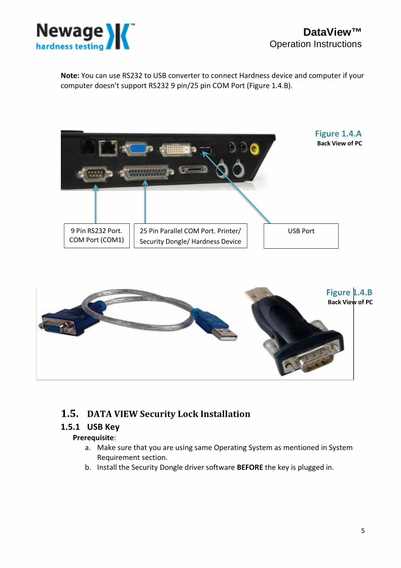
1) Plug the serial connector into the RS232 port on the hardness tester.2) Connect the 9 or 25 pin connector into the COM 1 or COM 2 port on the back of the PC.The Security dongle must be connected to USB Port in order for the software to work(Figure 1.4.A). If the Security dongle is not connected, the DataView application will run inDemo mode.
4
DataView™ Operation Instructions
Note: You can use RS232 to USB converter to connect Hardness device and computer if your computer doesn’t support RS232 9 pin/25 pin COM Port (Figure 1.4.B).
1.5. DATA VIEW Security Lock Installation 1.5.1 USB Key
Prerequisite: a. Make sure that you are using same Operating System as mentioned in System
Requirement section.b. Install the Security Dongle driver software BEFORE the key is plugged in.
9 Pin RS232 Port. COM Port (COM1)
25 Pin Parallel COM Port. Printer/ Security Dongle/ Hardness Device
USB Port
Figure 1.4.A Back View of PC
Figure 1.4.B Back View of PC
5
DataView™ Operation Instructions
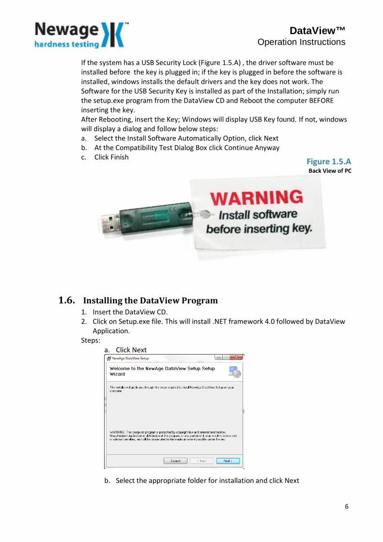
If the system has a USB Security Lock (Figure 1.5.A) , the driver software must be installed before the key is plugged in; if the key is plugged in before the software is installed, windows installs the default drivers and the key does not work. The Software for the USB Security Key is installed as part of the Installation; simply run the setup.exe program from the DataView CD and Reboot the computer BEFORE inserting the key. After Rebooting, insert the Key; Windows will display USB Key found. If not, windows will display a dialog and follow below steps: a. Select the Install Software Automatically Option, click Nextb. At the Compatibility Test Dialog Box click Continue Anywayc. Click Finish
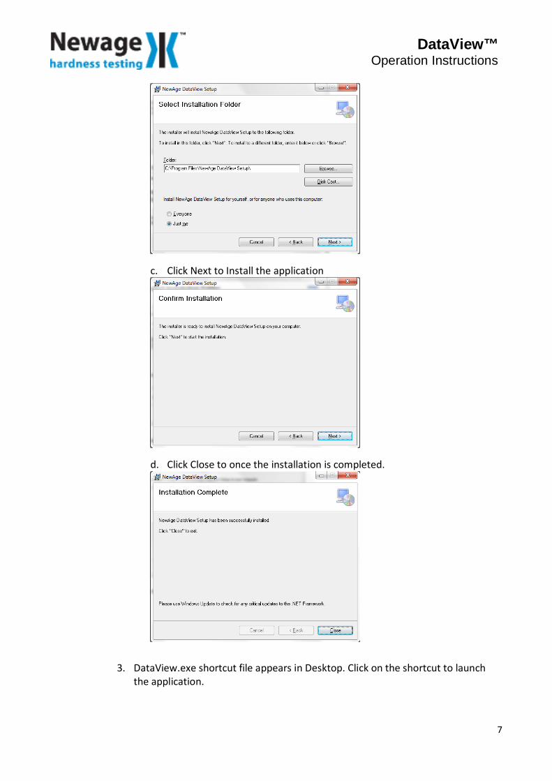
1.6. Installing the DataView Program 1. Insert the DataView CD.2. Click on Setup.exe file. This will install .NET framework 4.0 followed by DataView
Application.Steps:
a. Click Next
b. Select the appropriate folder for installation and click Next
Figure 1.5.A Back View of PC
6
DataView™ Operation Instructions
c. Click Next to Install the application
d. Click Close to once the installation is completed.
3. DataView.exe shortcut file appears in Desktop. Click on the shortcut to launch the application.
7
DataView™ Operation Instructions
4. Installed application contains sample test files named Sample1.xml, Sample2.xml, Sample3.xml, SampleCSV1.csv, SampleCSV2.csv, SampleCSV3.csv
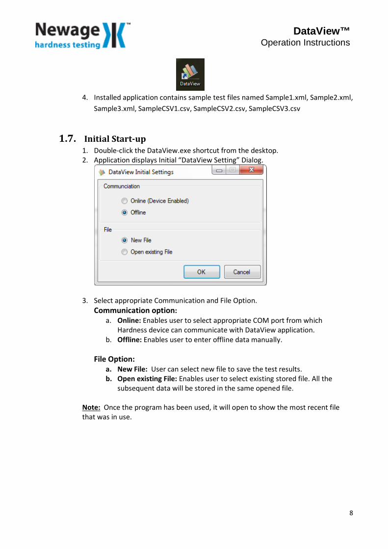
1.7. Initial Start-up 1. Double-click the DataView.exe shortcut from the desktop. 2. Application displays Initial “DataView Setting” Dialog.
3. Select appropriate Communication and File Option. Communication option:
a. Online: Enables user to select appropriate COM port from which Hardness device can communicate with DataView application.
b. Offline: Enables user to enter offline data manually. File Option:
a. New File: User can select new file to save the test results. b. Open existing File: Enables user to select existing stored file. All the
subsequent data will be stored in the same opened file.
Note: Once the program has been used, it will open to show the most recent file that was in use.
8
DataView™ Operation Instructions
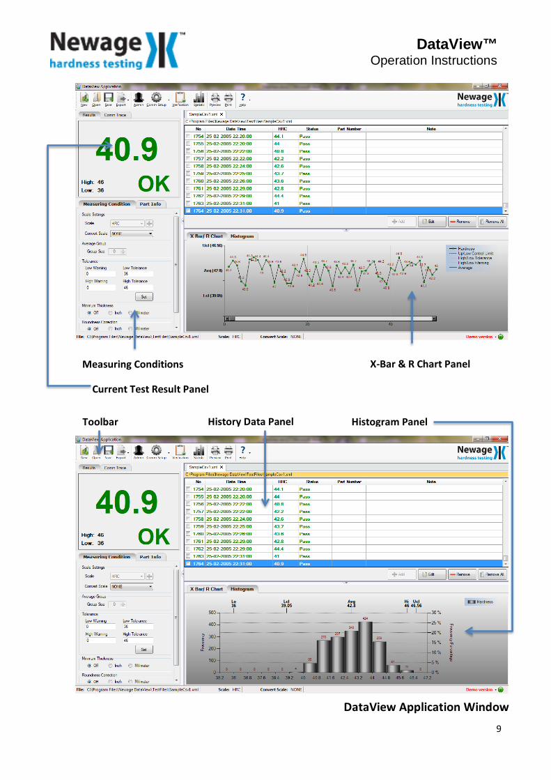
X-Bar & R Chart Panel
History Data Panel Histogram Panel
Measuring Conditions
Toolbar
Current Test Result Panel
DataView Application Window
9
DataView™ Operation Instructions
2. DataView Toolbar Options
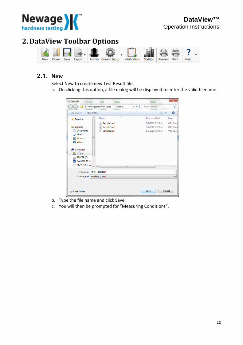
2.1. New Select New to create new Test Result file. a. On clicking this option, a file dialog will be displayed to enter the valid filename.
b. Type the file name and click Save. c. You will then be prompted for “Measuring Conditions”.
10
DataView™ Operation Instructions
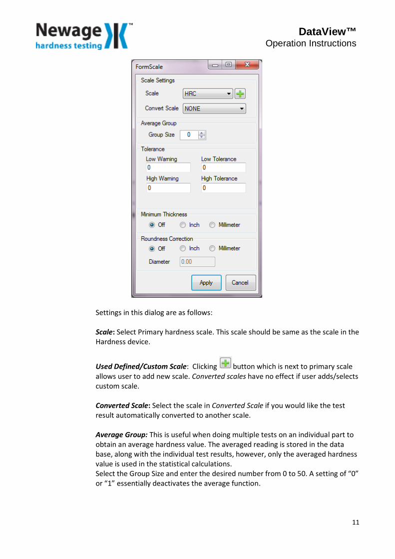
Settings in this dialog are as follows: Scale: Select Primary hardness scale. This scale should be same as the scale in the Hardness device.
Used Defined/Custom Scale: Clicking button which is next to primary scale allows user to add new scale. Converted scales have no effect if user adds/selects custom scale. Converted Scale: Select the scale in Converted Scale if you would like the test result automatically converted to another scale. Average Group: This is useful when doing multiple tests on an individual part to obtain an average hardness value. The averaged reading is stored in the data base, along with the individual test results, however, only the averaged hardness value is used in the statistical calculations. Select the Group Size and enter the desired number from 0 to 50. A setting of “0” or “1” essentially deactivates the average function.
11
DataView™ Operation Instructions
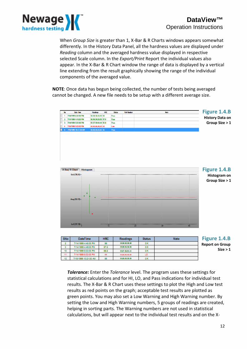
When Group Size is greater than 1, X-Bar & R Charts windows appears somewhat differently. In the History Data Panel, all the hardness values are displayed under Reading column and the averaged hardness value displayed in respective selected Scale column. In the Export/Print Report the individual values also appear. In the X-Bar & R Chart window the range of data is displayed by a vertical line extending from the result graphically showing the range of the individual components of the averaged value.
NOTE: Once data has begun being collected, the number of tests being averaged cannot be changed. A new file needs to be setup with a different average size.
Tolerance: Enter the Tolerance level. The program uses these settings for statistical calculations and for HI, LO, and Pass indications for individual test results. The X-Bar & R Chart uses these settings to plot the High and Low test results as red points on the graph; acceptable test results are plotted as green points. You may also set a Low Warning and High Warning number. By setting the Low and High Warning numbers, 5 groups of readings are created, helping in sorting parts. The Warning numbers are not used in statistical calculations, but will appear next to the individual test results and on the X-
Figure 1.4.B History Data on
Group Size > 1
Figure 1.4.B Histogram on
Group Size > 1
Figure 1.4.B Report on Group
Size > 1
12
DataView™ Operation Instructions
Bar/R Chart as grey points on the graph. Select the desired warning and tolerance values.
NOTE: Entering High and Low values of “0” will deactivate the Tolerance function. All readings will then be recorded without any tolerance indication although the calculated process limits will still appear in reports.
Minimum Thickness: Use this to have the minimum thickness requirement displayed for the current test result per Tables A5.1-A5.4 in ASTM E 18. Choose Off to deactivate the Minimum Thickness function, or Inches or Millimeters to activate it. The program will display the Minimum Thickness value for the current test result after each test is taken. The minimum thickness value appears on Result Panel. Roundness Correction (For use with Rockwell Scales Only): Use this function when testing on cylindrical surfaces to automatically add the round correction factor to the test result per Tables A6.1-A6.4 in ASTM E 18. Choose Inches or Millimeters to activate the Round Correction function, or Off to deactivate it. Set the desired Diameter. The selected round correction diameter appears on the bottom left of Result Panel, but there is no other indication that the results have been altered by the Round Correction factor.
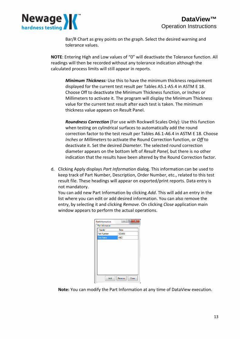
d. Clicking Apply displays Part Information dialog. This information can be used to keep track of Part Number, Description, Order Number, etc., related to this test result file. These headings will appear on exported/print reports. Data entry is not mandatory. You can add new Part Information by clicking Add. This will add an entry in the list where you can edit or add desired information. You can also remove the entry, by selecting it and clicking Remove. On clicking Close application main window appears to perform the actual operations.
Note: You can modify the Part Information at any time of DataView execution.
13
DataView™ Operation Instructions
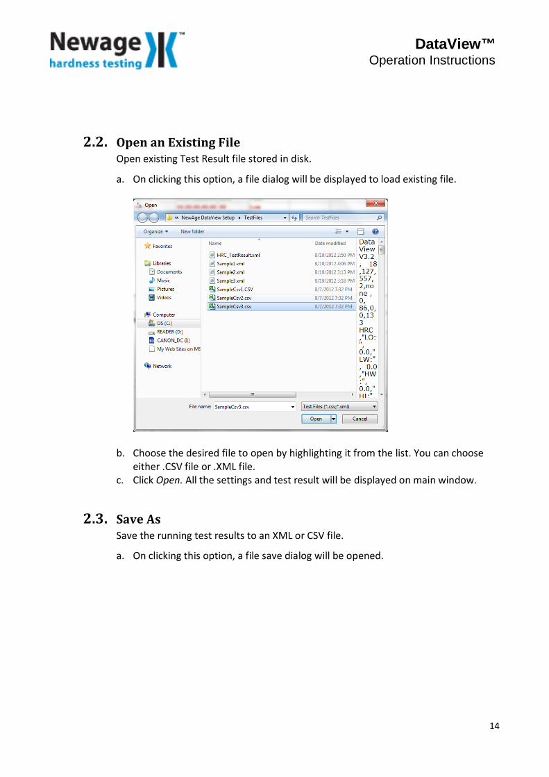
2.2. Open an Existing File Open existing Test Result file stored in disk.
a. On clicking this option, a file dialog will be displayed to load existing file.
b. Choose the desired file to open by highlighting it from the list. You can choose either .CSV file or .XML file.
c. Click Open. All the settings and test result will be displayed on main window.
2.3. Save As Save the running test results to an XML or CSV file.
a. On clicking this option, a file save dialog will be opened.
14
DataView™ Operation Instructions
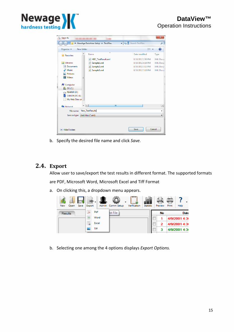
b. Specify the desired file name and click Save.
2.4. Export Allow user to save/export the test results in different format. The supported formats
are PDF, Microsoft Word, Microsoft Excel and Tiff Format
a. On clicking this, a dropdown menu appears.
b. Selecting one among the 4 options displays Export Options.
15
DataView™ Operation Instructions
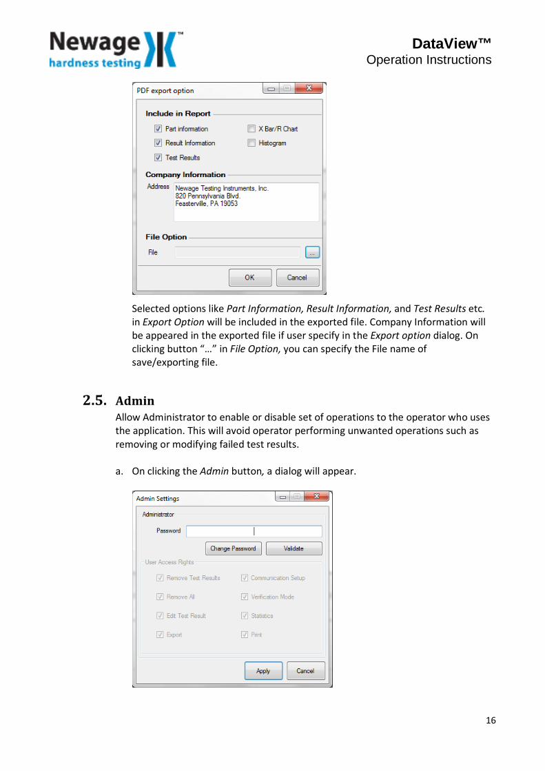
Selected options like Part Information, Result Information, and Test Results etc. in Export Option will be included in the exported file. Company Information will be appeared in the exported file if user specify in the Export option dialog. On clicking button “…” in File Option, you can specify the File name of save/exporting file.
2.5. Admin Allow Administrator to enable or disable set of operations to the operator who uses the application. This will avoid operator performing unwanted operations such as removing or modifying failed test results. a. On clicking the Admin button, a dialog will appear.
16
DataView™ Operation Instructions
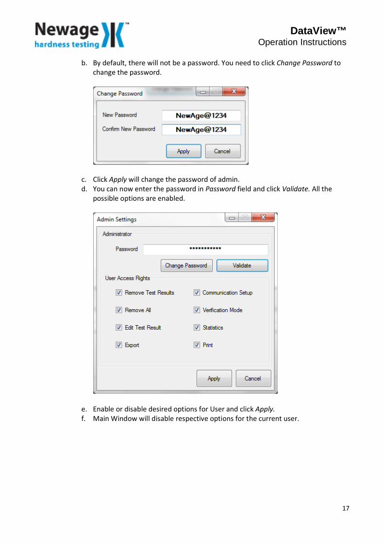
b. By default, there will not be a password. You need to click Change Password to change the password.
c. Click Apply will change the password of admin. d. You can now enter the password in Password field and click Validate. All the
possible options are enabled.
e. Enable or disable desired options for User and click Apply. f. Main Window will disable respective options for the current user.
17
DataView™ Operation Instructions
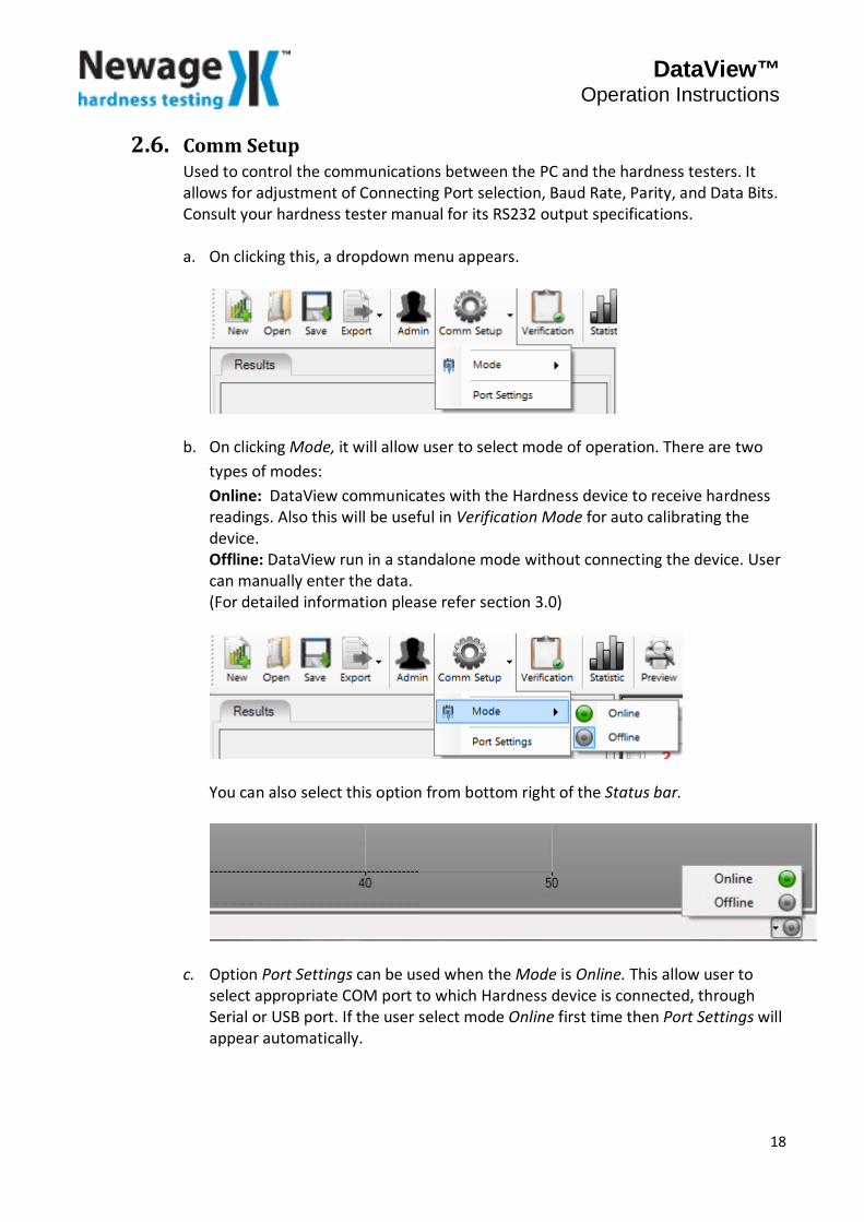
2.6. Comm Setup Used to control the communications between the PC and the hardness testers. It allows for adjustment of Connecting Port selection, Baud Rate, Parity, and Data Bits. Consult your hardness tester manual for its RS232 output specifications. a. On clicking this, a dropdown menu appears.
b. On clicking Mode, it will allow user to select mode of operation. There are two types of modes: Online: DataView communicates with the Hardness device to receive hardness readings. Also this will be useful in Verification Mode for auto calibrating the device. Offline: DataView run in a standalone mode without connecting the device. User can manually enter the data. (For detailed information please refer section 3.0)
You can also select this option from bottom right of the Status bar.
c. Option Port Settings can be used when the Mode is Online. This allow user to select appropriate COM port to which Hardness device is connected, through Serial or USB port. If the user select mode Online first time then Port Settings will appear automatically.
18
DataView™ Operation Instructions
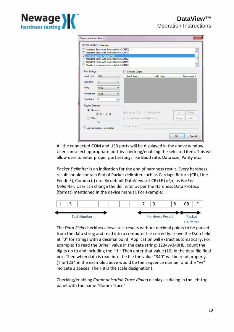
All the connected COM and USB ports will be displayed in the above window. User can select appropriate port by checking/enabling the selected item. This will allow user to enter proper port settings like Baud rate, Data size, Parity etc. Packet Delimiter is an indication for the end of hardness result. Every hardness result should contain End of Packet delimiter such as Carriage Return (CR), Line-Feed(LF), Comma (,) etc. By default DataView set CR+LF (\r\n) as Packet Delimiter. User can change the delimiter as per the Hardness Data Protocol (format) mentioned in the device manual. For example:
1 5 7 3 . 8 CR LF The Data Field checkbox allows test results without decimal points to be parsed from the data string and read into a computer file correctly. Leave the Data field at “0” for strings with a decimal point. Application will extract automatically. For example: To read the Brinell value in the data string: 1234vv340HB, count the digits up to and including the “H.” Then enter that value (10) in the data file field box. Then when data is read into the file the value “340” will be read properly. (The 1234 in the example above would be the sequence number and the “vv" indicate 2 spaces. The HB is the scale designation). Checking/enabling Communication Trace dialog displays a dialog in the left top panel with the name “Comm Trace”.
Test Number Hardness Result Packet Delimiter
19
DataView™ Operation Instructions
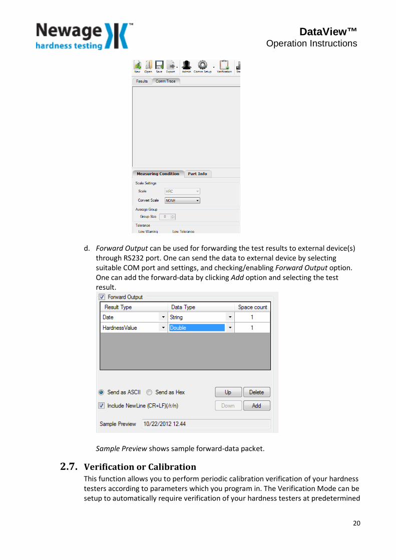
d. Forward Output can be used for forwarding the test results to external device(s) through RS232 port. One can send the data to external device by selecting suitable COM port and settings, and checking/enabling Forward Output option. One can add the forward-data by clicking Add option and selecting the test result.
Sample Preview shows sample forward-data packet.
2.7. Verification or Calibration This function allows you to perform periodic calibration verification of your hardness testers according to parameters which you program in. The Verification Mode can be setup to automatically require verification of your hardness testers at predetermined
20

DataView™ Operation Instructions
intervals. After the verification has been run, the program will confirm the tester’s compliance with your programmed parameters and print out a Verification Certificate, or notify you if the equipment is out of spec. There are 6 user assignable parameters to setup for running verifications: Tester, Scale, Range, ASTM Spec, Test Block Description, and Schedule Verification (Every interval) a. Select the Verification from Toolbar. Verification Setup dialog appears:
Tester - Create a list of the testers you will be verifying using the Manufacturer Name, Model Number, and Serial Number. The program will then keep a record of each unit’s verification history. You can create a new tester just by editing the fields under Tester. Already stored tester data will be appeared by clicking the respective drop down box. Note: For verification all the Tester field such as Manufacturer, Model, Serial no is mandatory. Scale and Range: Choose the Scale you wish to verify from the list. Select the range from High, Medium, and Low. Acceptance Criteria: Designate the Maximum Deviation and Maximum Range allowed by the ASTM Spec you need to conform to. As per the ASTM spec Maximum Deviation refers to “Error” and Maximum Range refers to “Repeatability”.
Test Block Description: Designate the Hardness (Block) Value, Serial Number, Block Manufacturer and Average Group Size of the Test Block. Enter the nominal value of block and Average Group Size. Also enter Serial No. and Manufacturer Name.
21
DataView™ Operation Instructions
Schedule Verification: Use this function to have the program automatically launch into the Verify Mode at regular intervals.
1. Assign the time frame in either Hours or Days by clicking on the appropriate option.
2. Enter the interval in Verify Every field.
b. You may run a verification at this time by clicking on the Start Verification button, OR click on OK to save the setup to run at the designated time interval. Verify Data allow user to view stored verify data which is calibrated/verified last time for respective tester.
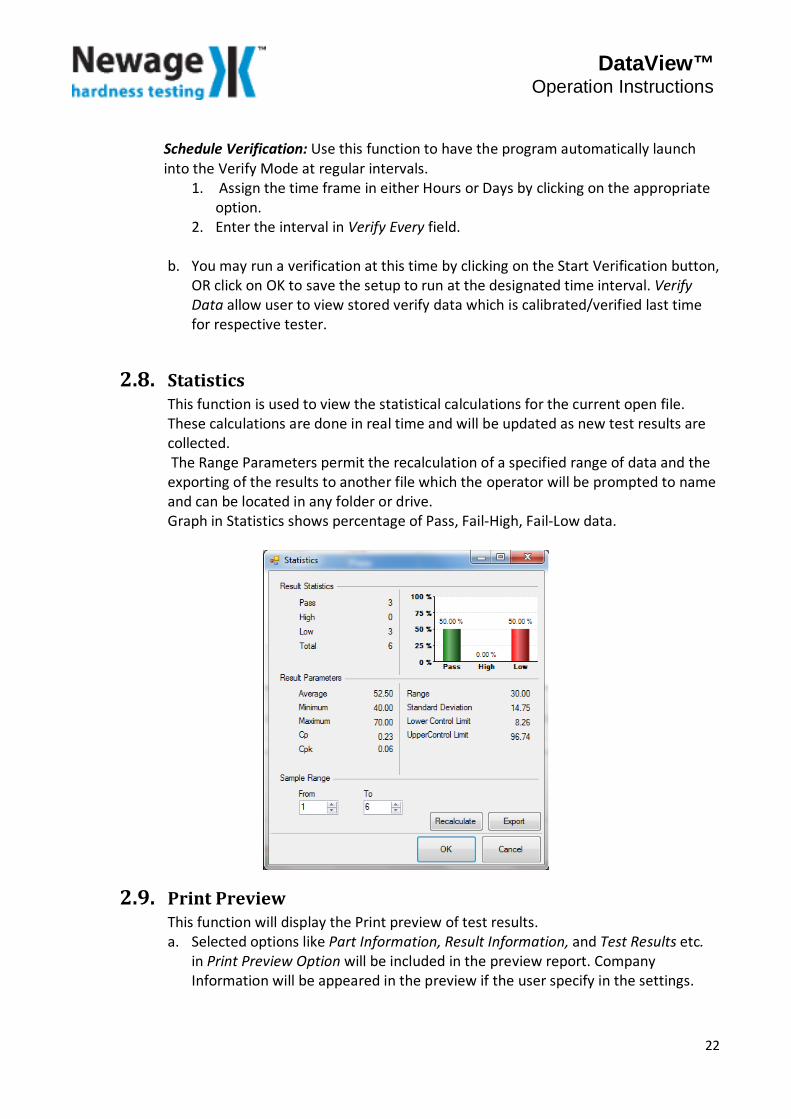
2.8. Statistics This function is used to view the statistical calculations for the current open file. These calculations are done in real time and will be updated as new test results are collected. The Range Parameters permit the recalculation of a specified range of data and the exporting of the results to another file which the operator will be prompted to name and can be located in any folder or drive. Graph in Statistics shows percentage of Pass, Fail-High, Fail-Low data.
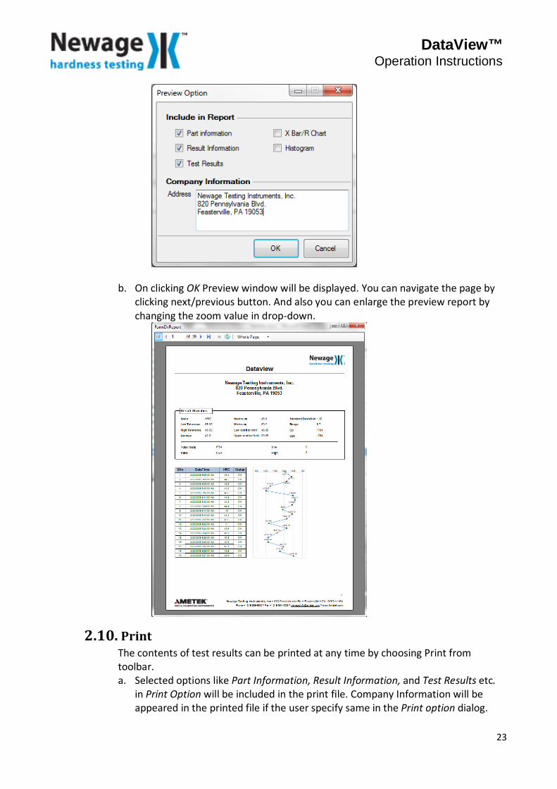
2.9. Print Preview This function will display the Print preview of test results. a. Selected options like Part Information, Result Information, and Test Results etc.
in Print Preview Option will be included in the preview report. Company Information will be appeared in the preview if the user specify in the settings.
22
DataView™ Operation Instructions
b. On clicking OK Preview window will be displayed. You can navigate the page by clicking next/previous button. And also you can enlarge the preview report by changing the zoom value in drop-down.
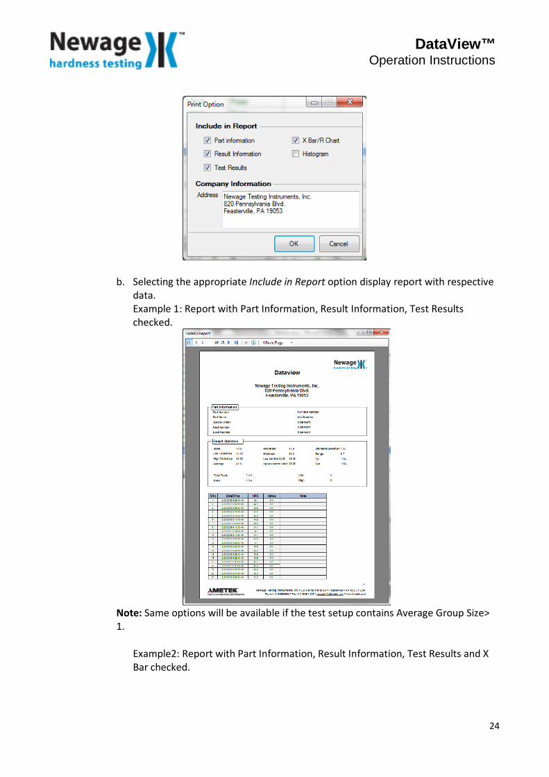
2.10. Print The contents of test results can be printed at any time by choosing Print from toolbar. a. Selected options like Part Information, Result Information, and Test Results etc.
in Print Option will be included in the print file. Company Information will be appeared in the printed file if the user specify same in the Print option dialog.
23
DataView™ Operation Instructions
b. Selecting the appropriate Include in Report option display report with respective data. Example 1: Report with Part Information, Result Information, Test Results checked.
Note: Same options will be available if the test setup contains Average Group Size> 1.
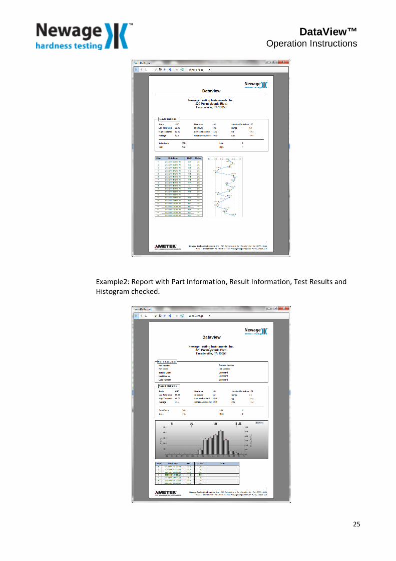
Example2: Report with Part Information, Result Information, Test Results and X Bar checked.
24
DataView™ Operation Instructions
Example2: Report with Part Information, Result Information, Test Results and Histogram checked.
25
DataView™ Operation Instructions
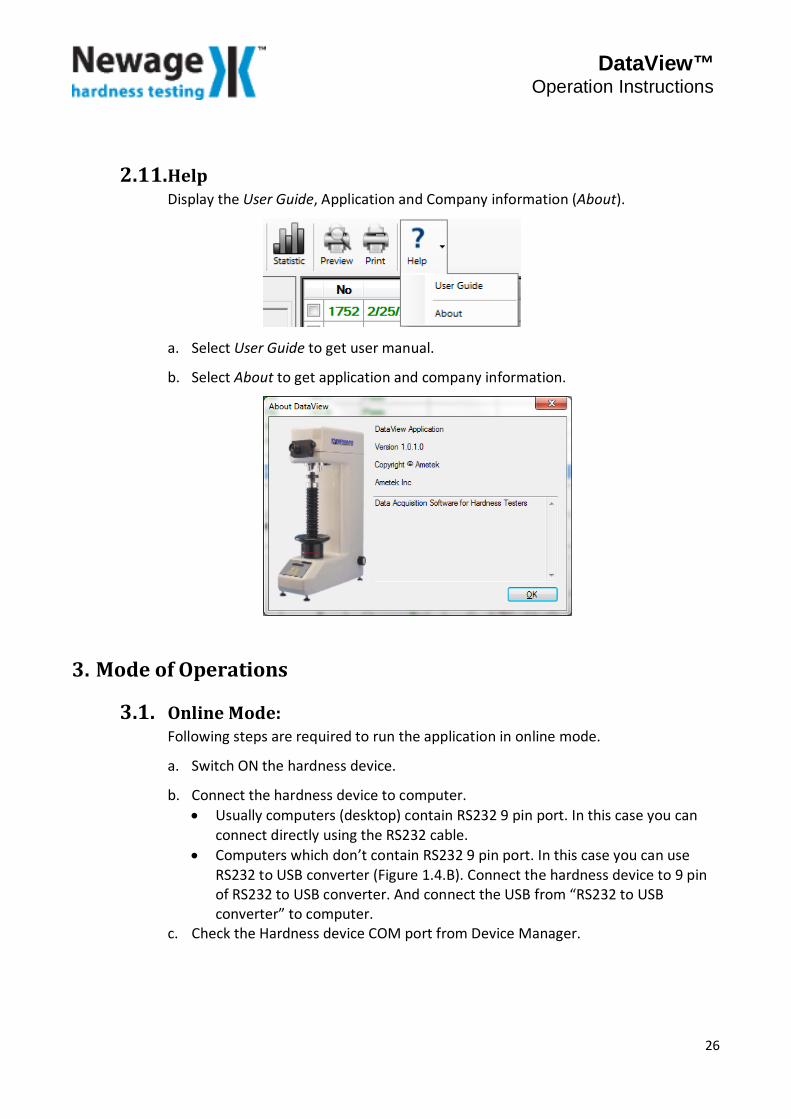
2.11. Help Display the User Guide, Application and Company information (About).
a. Select User Guide to get user manual.
b. Select About to get application and company information.
3. Mode of Operations
3.1. Online Mode: Following steps are required to run the application in online mode.
a. Switch ON the hardness device.
b. Connect the hardness device to computer. • Usually computers (desktop) contain RS232 9 pin port. In this case you can
connect directly using the RS232 cable. • Computers which don’t contain RS232 9 pin port. In this case you can use
RS232 to USB converter (Figure 1.4.B). Connect the hardness device to 9 pin of RS232 to USB converter. And connect the USB from “RS232 to USB converter” to computer.
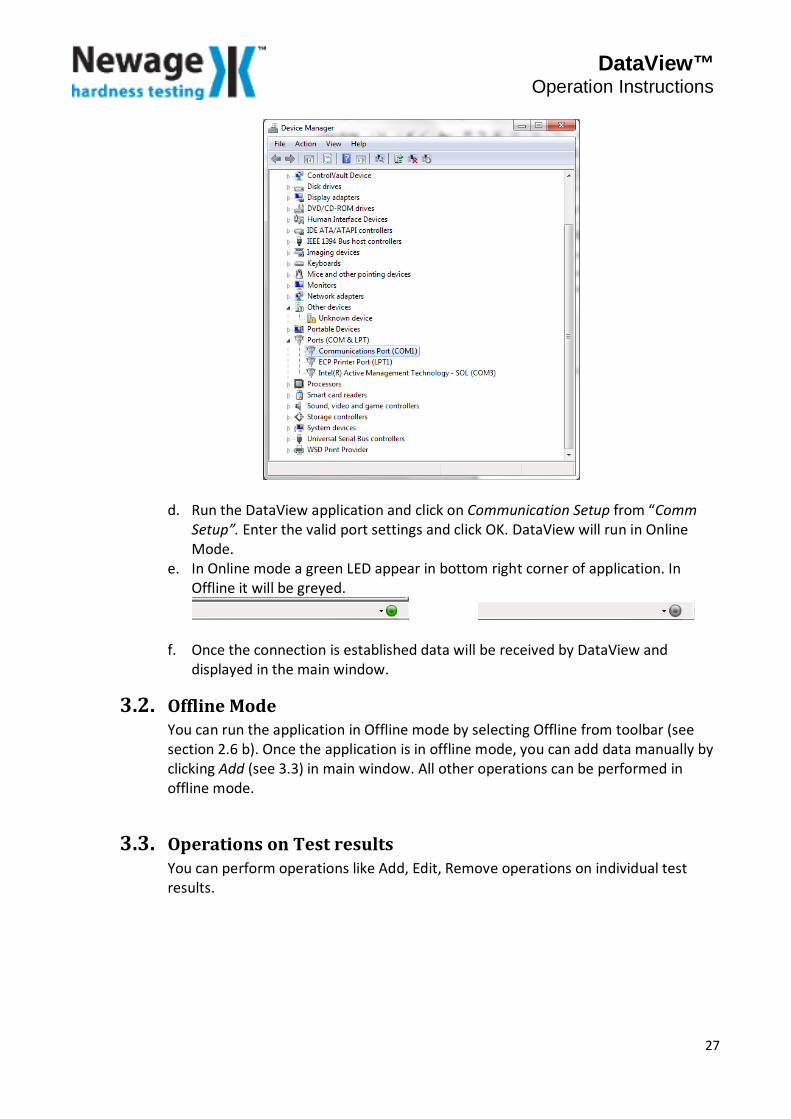
c. Check the Hardness device COM port from Device Manager.
26
DataView™ Operation Instructions
d. Run the DataView application and click on Communication Setup from “Comm Setup”. Enter the valid port settings and click OK. DataView will run in Online Mode.
e. In Online mode a green LED appear in bottom right corner of application. In Offline it will be greyed.
f. Once the connection is established data will be received by DataView and displayed in the main window.
3.2. Offline Mode You can run the application in Offline mode by selecting Offline from toolbar (see section 2.6 b). Once the application is in offline mode, you can add data manually by clicking Add (see 3.3) in main window. All other operations can be performed in offline mode.
3.3. Operations on Test results You can perform operations like Add, Edit, Remove operations on individual test results.
27

DataView™ Operation Instructions
3.4. Add Allow user to add hardness reading manually. Clicking on Add display a dialog where you can add hardness reading. a. If the Group Size is 0 or 1.
b. If the Group Size greater than 1.
Add New Test Result Edit Test Result
Remove Test Result
28
DataView™ Operation Instructions
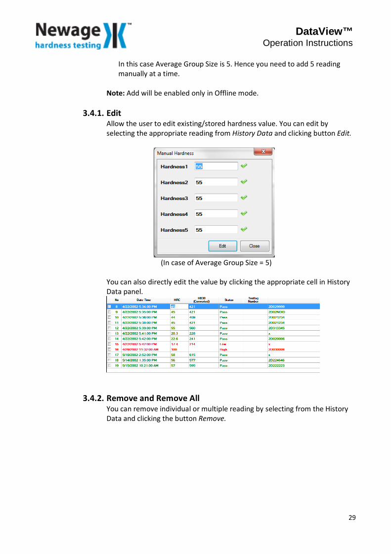
In this case Average Group Size is 5. Hence you need to add 5 reading manually at a time.
Note: Add will be enabled only in Offline mode.
3.4.1. Edit Allow the user to edit existing/stored hardness value. You can edit by selecting the appropriate reading from History Data and clicking button Edit.
(In case of Average Group Size = 5) You can also directly edit the value by clicking the appropriate cell in History Data panel.
3.4.2. Remove and Remove All You can remove individual or multiple reading by selecting from the History Data and clicking the button Remove.
29
DataView™ Operation Instructions
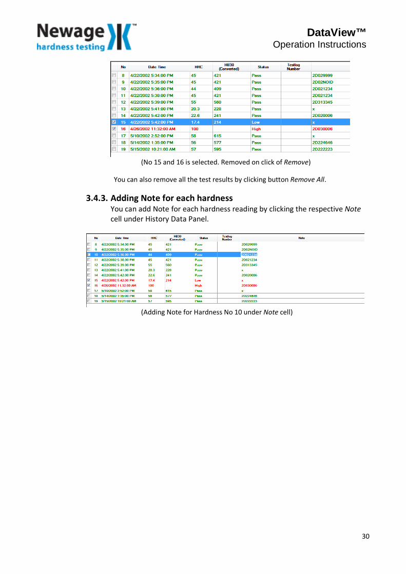
(No 15 and 16 is selected. Removed on click of Remove)
You can also remove all the test results by clicking button Remove All.
3.4.3. Adding Note for each hardness You can add Note for each hardness reading by clicking the respective Note cell under History Data Panel.
(Adding Note for Hardness No 10 under Note cell)
30

www.hardnesstesters.com
Information in this document is subject to change without notice. ©2015 by AMETEK, Inc., www.ametek.com. All rights reserved.
Newage Testing Instruments, Inc.205 Keith Valley RoadHorsham PA 19044, USA
Tel: 215-355-6900Fax: [email protected]
Pub Code: Opman-DataView • Issue: 1510Newagehardness testing
AMETEK Denmark (Scandinavia) Tel +45 4816 8000 • [email protected]
Lloyd Instruments Ltd. (UK) Tel +44 (0) 1243 833 370 • [email protected]
AMETEK SAS (France) Tel +33 (0) 1 30 68 89 40 • [email protected]
AMETEK Europe GmbH (Germany) Tel +49 0 2159 9136 70 • [email protected]
AMETEK Singapore Pvt. Ltd. (Singapore) Tel +65 484 2388 • [email protected]