newera usit system kit 00320 (eng...newera usit system approved universal safety 1986 since impact...
TRANSCRIPT
www.mimsafe.se
TABLE KITASSEMBLY INSTRUCTIONS
NEWERA USIT SYSTEM
APPROVED
UNIVERSAL SAFETY
1986SINCE
IMPACT TECHNOLOGY
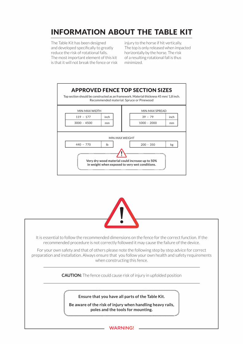
INFORMATION ABOUT THE TABLE KITThe Table Kit has been designed and developed specifically to greatly reduce the risk of rotational falls. The most important element of this kit is that it will not break the fence or risk
injury to the horse if hit vertically. The top is only released when impacted horizontally by the horse. The risk of a resulting rotational fall is thus minimized.
It is essential to follow the recommended dimensions on the fence for the correct function. If the recommended procedure is not correctly followed it may cause the failure of the device.
For your own safety and that of others please note the following step by step advice for correct preparation and installation. Always ensure that you follow your own health and safety requirements
when constructing this fence.
CAUTION: The fence could cause risk of injury in upfolded position
WARNING!
Ensure that you have all parts of the Table Kit.
Be aware of the risk of injury when handling heavy rails, poles and the tools for mounting.
Very dry wood material could increase up to 50% in weight when exposed to very wet conditions.
Top section should be constructed as an framework. Material thickness 45 mm/ 1,8 inch. Recommended material: Spruce or Pinewood
APPROVED FENCE TOP SECTION SIZES
MIN-MAX WIDTH
inch119 – 177
mm3000 - 4500
MIN-MAX WEIGHT
lb440 – 770 kg200 - 350
MIN-MAX SPREAD
inch39 – 79
mm1000 - 2000
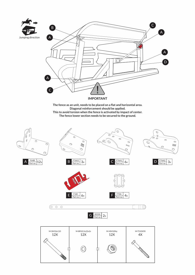
4X12X12X12XM-TS10X90M-MM10NyM-BR10,5x22x2sM-SM10x110
Jumping direction
B
A
C
A
A
A
D
C
IMPORTANT
The fence as an unit, needs to be placed on a flat and horizontal area. Diagonal reinforcement should be applied.
This to avoid torsion when the fence is activated by impact of center.The fence lower section needs to be secured to the ground.
A F64B
Part no 12X B F76A3
Part no 3X C F76A1
Part no 6X D F76A2
Part no 3X
G 00330
Part no 2X
E F18C
Part no 6X F F70A
Part no 4X
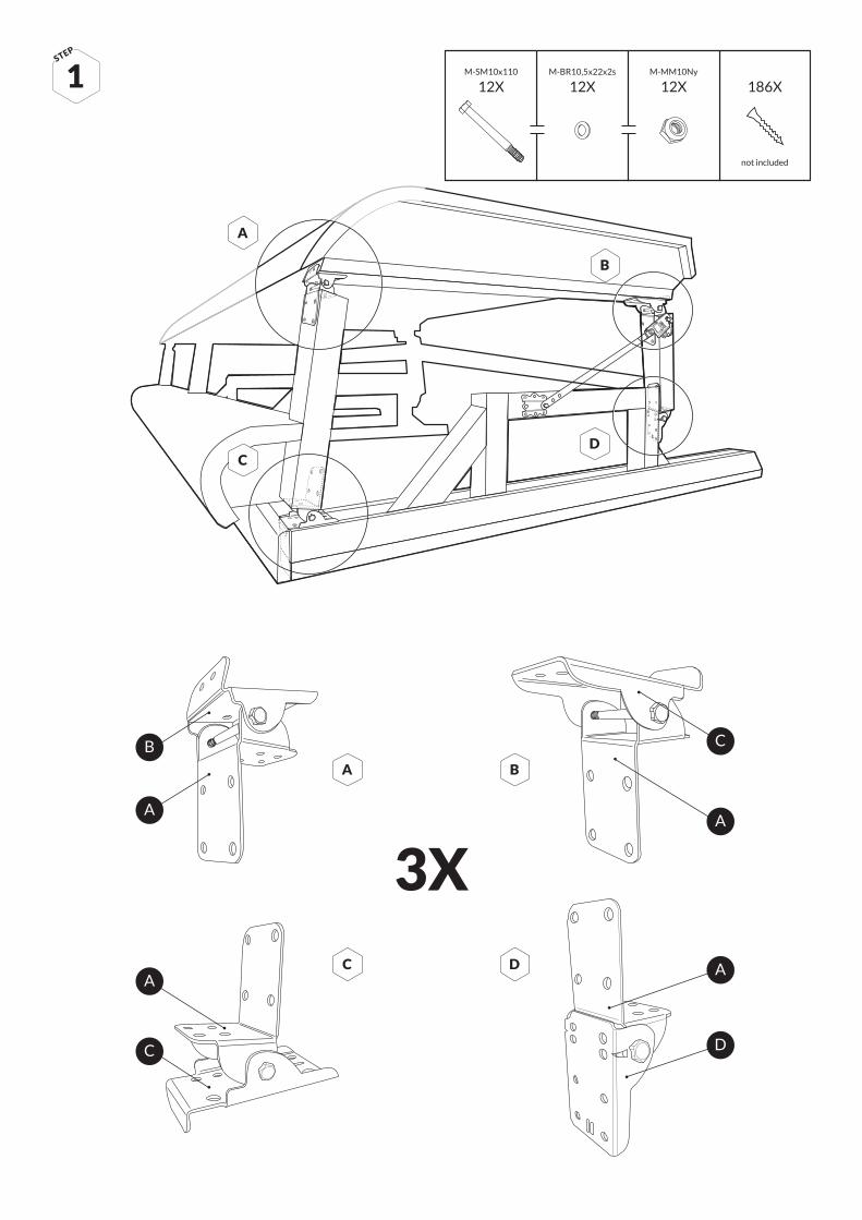
3XA
A
C D
B C
AA
1STEP
C
A
A B
C D
D
B
12X12X12XM-MM10NyM-BR10,5x22x2sM-SM10x110
186X
not included
1
2
3
56
7
8
9
BC
D E
45
45
4
60
A
F
G2 H2G1H110
10 9
Instruction: Decide length A(milimeter)
Instruction: Decide length A(inch)
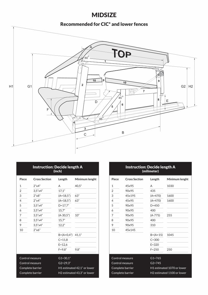
Recommended for CIC* and lower fences
MIDSIZE
Piece Cross Section Length Minimum lenght
1 45x95 A 1030
2 90x95 435
3 45x195 (A+470) 1600
4 45x95 (A+470) 1600
5 90x95 D=450
6 90x95 400
7 90x95 (A-775) 255
8 90x95 400
9 90x95 310
10 45x145
B=(A+15) 1045
C=300
E=320
F=250 250
Control measure G1=765
Control measure G2=745
Complete barrier H1 estimated 1070 or lower
Complete barrier H2 estimated 1100 or lower
Piece Cross Section Length Minimum lenght
1 2”x4” A 40,5”
2 3,5”x4” 17,1”
3 2”x8” (A+18,5”) 63”
4 2”x4” (A+18,5”) 63”
5 3,5”x4” D=17,7”
6 3,5”x4” 15,7”
7 3,5”x4” (A-30,5”) 10”
8 3,5”x4” 15,7”
9 3,5”x4” 12,2”
10 2”x6”
B=(A+0,4”) 41,1”
C=11,8
E=12,6
F=9,8” 9,8”
Control measure G1=30,1”
Control measure G2=29,3”
Complete barrier H1 estimated 42,1” or lower
Complete barrier H2 estimated 43,3” or lower
Instruction: Decide length A(milimeter)
Instruction: Decide length A(inch)
1
2
3
56
7
8
9
BC
D E
45
45
4
60
A
F
G2 H2G1H110
10 9
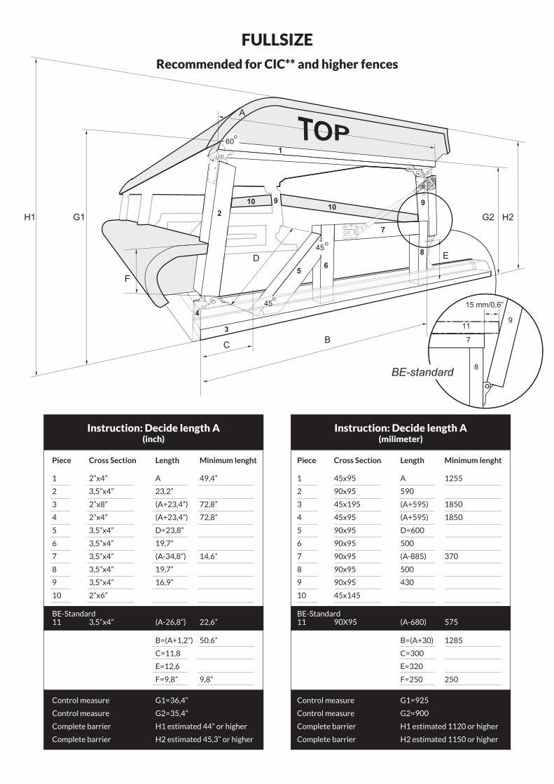
Recommended for CIC** and higher fences
FULLSIZE
Piece Cross Section Length Minimum lenght
1 45x95 A 1255
2 90x95 590
3 45x195 (A+595) 1850
4 45x95 (A+595) 1850
5 90x95 D=600
6 90x95 500
7 90x95 (A-885) 370
8 90x95 500
9 90x95 430
10 45x145
BE-Standard11 90X95 (A-680) 575
B=(A+30) 1285
C=300
E=320
F=250 250
Control measure G1=925
Control measure G2=900
Complete barrier H1 estimated 1120 or higher
Complete barrier H2 estimated 1150 or higher
Piece Cross Section Length Minimum lenght
1 2”x4” A 49,4”
2 3,5”x4” 23,2”
3 2”x8” (A+23,4”) 72,8”
4 2”x4” (A+23,4”) 72,8”
5 3,5”x4” D=23,8”
6 3,5”x4” 19,7”
7 3,5”x4” (A-34,8”) 14,6”
8 3,5”x4” 19,7”
9 3,5”x4” 16,9”
10 2”x6”
BE-Standard11 3,5”x4” (A-26,8”) 22,6”
B=(A+1,2”) 50,6”
C=11,8
E=12,6
F=9,8” 9,8”
Control measure G1=36,4”
Control measure G2=35,4”
Complete barrier H1 estimated 44” or higher
Complete barrier H2 estimated 45,3” or higher
7
911
BE-standard
15 mm/0,6”
8
2
3
56
7
8
9
4
1010 9
1010
9
99
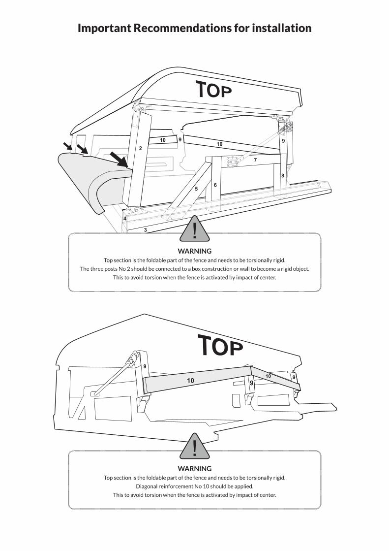
Important Recommendations for installation
WARNINGTop section is the foldable part of the fence and needs to be torsionally rigid.
The three posts No 2 should be connected to a box construction or wall to become a rigid object.
This to avoid torsion when the fence is activated by impact of center.
WARNINGTop section is the foldable part of the fence and needs to be torsionally rigid.
Diagonal reinforcement No 10 should be applied.
This to avoid torsion when the fence is activated by impact of center.
www.mimsafe.seTable Kit - 00320 Edition 2018-01
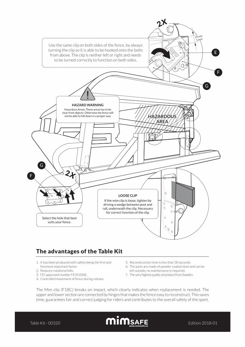
The advantages of the Table Kit
1. It has been produced with safety being the first and foremost important factor.
2. Reduces rotational falls.3. FEI approved number FEI01SWE.4. Controlled movement of fence during release.
5. Reconstruction time is less than 30 seconds.6. The parts are made of powder coated steel and can be
left outside, no maintenance is required.7. The very highest quality of product from Sweden.
The Mim clip (F18C) breaks on impact, which clearly indicates when replacement is needed. The upper and lower section are connected by hinges that makes the fence easy to reconstruct. This saves time, guarantees fair and correct judging for riders and contributes to the overall safety of the sport.
HAZARDIOUS AREA
HAZARDIOUS AREA
HAZARDIOUS AREA
HAZARD WARNINGHazardous Areas: These areas has to be
clear from objects. Otherwise the fence will not be able to fall down in a proper way.
2X
LOOSE CLIP
If the mim clip is loose, tighten by driving a wedge between post and
rail, underneath the clip. Necessary for correct function of the clip.
Select the hole that best suits your fence.
2X
25 mm
1 inch
Use the same clip on both sides of the fence, by always turning the clip so it is able to be hooked onto the bolts
from above. The clip is neither left or right and needs to be turned correctly to function on both sides.
G
G
F
F
E
HAZARDOUSAREA