newproducts - mitutoyo south asia pvt. ltd. accuracy cnc cmm microcord strato-apex series refer to...
TRANSCRIPT
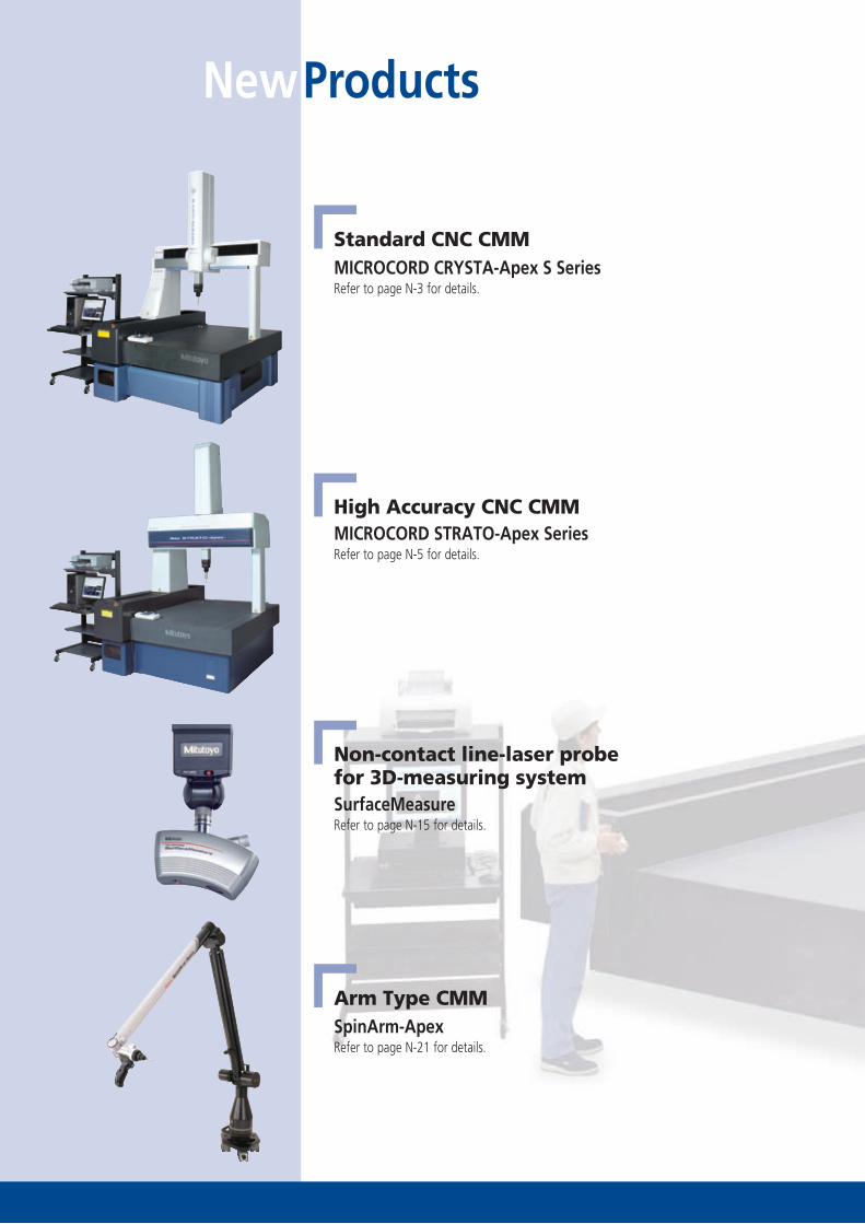
High Accuracy CNC CMMMICROCORD STRATO-Apex SeriesRefer to page N-5 for details.
Standard CNC CMMMICROCORD CRYSTA-Apex S SeriesRefer to page N-3 for details.
NewProducts
Arm Type CMMSpinArm-ApexRefer to page N-21 for details.
Non-contact line-laser probe for 3D-measuring systemSurfaceMeasureRefer to page N-15 for details.

N-2
Coordinate Measuring Machines
INDEXMICROCORD (CMM)CRYSTA-Apex S500/700/900 Series N-3CRYSTA-Apex S1200 Series N-4Crysta-Apex C1600/2000 Series STRATO-Apex 700/900 Series N-5FALCIO-Apex 1600 Series N-6FALCIO-Apex 2000/3000 Series N-6LEGEX Series N-7Crysta-Apex C203016G/306020G N-8CARBstrato N-9CARBapex N-10MACH-3A 653 N-11MACH-V 9106 N-11MACH Ko-ga-me N-12Crysta-Plus M Series N-13, N-14QM-Data300 N-14CMM Probes N-15, N-16MCOSMOS N-17, N-18MSURF N-19, N-20SpinArm-Apex N-21Quick Guide to Precision Measuring Instruments N-22
MICROCORD (CMM)Coordinate Measuring Machines
N
N
Note: All Mitutoyo CNC CMM's manufactured since 2008 incorporate a main unit Startup system (relocation detection system), which disables operation when an unexpected vibration has occurred or the machine has been relocated. Be sure to contact your nearest Mitutoyo Sales Office prior to relocating your machine after initial installation.

N-3
N
Coordinate Measuring MachinesPrecision measuring technology with three dimensions
Mitutoyo operates a policy of continuous improvement that aims to provide the customer with the benefit of the latest technological advances.Therefore the company reserves the right to change any or all aspects of any product specification without notice.
Standard CNC CMMMICROCORD CRYSTA-Apex S500/700/900 Series
•TheCRYSTA-ApexS500/700/900series,CNCCMMs attain high accuracy (1/7μm), high speed, and high acceleration. This series offers flexibility with a wide variety of models for various workpiece sizes.
• The scale systems on Mitutoyo high-pre-cision models utilizes a high-performance linear encoder (manufactured by Mitutoyo), for detecting axis position. In addition, vari-ous technologies have been utilized in the structure, part processing, and assembly to provide high accuracy measurement.
• Floor vibration at the installation location, can be a source of variations in measured values. The auto-leveling air spring vibra-tion isolator is available as an option for CRYSTA-Apex S500/700/900 series. The vibration isolator insulates the main unit from floor vibrations and can quickly levels the CMM main unit, using a sensor that detects load fluctuations caused by axis movement of the CMM or workpiece loading.
• All Crysta-Apex S high-precision series CMM's are equipped with temperature compensation and therefore do not require a temperature controlled room. Accuracy is guaranteed within the range of 16 to 26°C.
CRYSTA-Apex S 544 CRYSTA-Apex S 776 CRYSTA-Apex S 9106
●CRYSTA-Apex S 500/700/900 Series Temperature Limits
●CRYSTA-Apex S 500/700/900 Series Accuracy JIS B7440-2 (2003)
Model Items CRYSTA-Apex S 544 CRYSTA-Apex S 574 CRYSTA-Apex S 776 CRYSTA-Apex S 7106 CRYSTA-Apex S
9106 (Z600) /9108 (Z800) CRYSTA-Apex S
9166 (Z600) /9168 (Z800) CRYSTA-Apex S
9206 (Z600) /9208 (Z800)
Measuring range
X axis 500mm 700mm 900mmY axis 400mm 700mm 700mm 1000mm 1000mm 1600mm 2000mmZ axis 400mm 600mm 600mm/800mm
Maximum measuring speed 8mm/s 8mm/s 8mm/s (3mm/s for Z800 type)
Drive speed
Each axis 8 to 300mm/s (CNC Mode), Maximum combined speed 519mm/s0 to 80mm/s (J/S Mode: High Speed)0 to 3mm/s (J/S Mode: Low Speed)0.05mm/s (J/S Mode: Fine Speed)
Each axis 8 to 300mm/s (CNC Mode), Maximum combined speed 519mm/s0 to 80mm/s (J/S Mode: High Speed)0 to 3mm/s (J/S Mode: Low Speed)0.05mm/s (J/S Mode: Fine Speed)
Each axis 8 to 300mm/s (CNC Mode), Maximum combined speed 519mm/s0 to 80mm/s (J/S Mode: High Speed)0 to 3mm/s (J/S Mode: Low Speed)0.05mm/s (J/S Mode: Fine Speed)
Maximum acceleration Each axis 1333mm/s2,Maximum combined speed 2309mm/s2
Each axis 1333mm/s2,Maximum combined speed 2309mm/s2
Each axis 1333mm/s2 (1000mm/s2 for Z800 type)Maximum combined speed 2309mm/s2 (1732mm/s2 for Z800 type)
Resolution 0.0001mm (0.1μm) 0.0001mm (0.1μm) 0.0001mm (0.1μm)Guide method Air bearings on each axis Air bearings on each axis Air bearings on each axisMaximum measurable height 545mm 800mm 800mm (Z=600mm)/1000mm (Z=800mm)Maximum table loading 180kg 800kg 1000kg 1200kg 1500kg 1800kgMass (including the control device and installation platform)
515kg 625kg 1675kg 1951kg2231kg (Z=600mm) 2868kg (Z=600mm) 3912kg (Z=600mm)
2261kg (Z=800mm) 2898kg (Z=800mm) 3942kg (Z=800mm)
Air supply Pressure 0.4MPa 0.4MPa 0.4MPaConsumption 50L/min under normal conditions (air source: 100L/min) 60L/min under normal conditions (air source: 120L/min) 60L/min under normal conditions (air source: 120L/min)
Note: While the appearance of the natural stone measuring table varies according to the source, the high stability for which this material is known can always be relied upon.
Probe used Maximum permissible error (MPEE) Maximum permissible probing error (MPEP)
SP25M(Stylus: ø4×50mm)
1.7+3L/1000(Temperature environment 1)1.7+4L/1000(Temperature environment 2) 1.7
TP200(Stylus: ø4×10mm)
1.9+3L/1000(Temperature environment 1)1.9+4L/1000(Temperature environment 2) 1.9
TP20(Stylus: ø4×10mm)
2.2+3L/1000(Temperature environment 1)2.2+4L/1000(Temperature environment 2) 2.2
Notes: (1) L = measured length (mm); (2) For temperature environments 1 and 2, refer to the Temperature Limits table on right.
Temperature environment 1 Temperature environment 2
Limits within which accuracy is guaranteed
Range 18 to 22℃ 16 to 26℃
Rate of change 2.0K per hour or less2.0K in 24 hours or less
2.0K per hour or less5.0K in 24 hours or less
Gradient 1.0K or less per meter 1.0K or less per meter
Unit (μm) ●CRYSTA-Apex S 500/700/900 Series Scanning Accuracy JIS B7440-4(2003)Probe used Maximum permissible scanning error (MPETHP)SP25M(Stylus:ø4×50mm) 2.3
Unit (μm)
SPECIFICATIONS

N-4
N
Mitutoyo operates a policy of continuous improvement that aims to provide the customer with the benefit of the latest technological advances.Therefore the company reserves the right to change any or all aspects of any product specification without notice.
• The CRYSTA-Apex S1200 series and Crysta-Apex C1600/2000 series are large-sized CNC CMMs developed for supporting quality evaluation of large parts.
• The scale systems on Mitutoyo high-precision models utilizes a high-perfor-mance linear encoder (manufactured by Mitutoyo), for detecting axis position. In addition, various technologies have been utilized in the structure, part pro-cessing, and assembly to provide high accuracy measurement.
Standard CNC CMMMICROCORD CRYSTA-Apex S1200 SeriesMICROCORD Crysta-Apex C1600/C2000 Series
• Floor vibration at the installation location, can be a source of variations in measured values. The auto-leveling air spring vibra-tion isolator is available as an option for CRYSTA-Apex S1200 & Crysta-Apex C1600/2000 series. The vibration isolator
insulates the main unit from floor vibrations and can quick-ly levels the CMM main unit, using a sensor that detects load fluctuations caused by
axis movement of the CMM or work-piece loading.
• All CRYSTA-Apex S1200 & Crysta-Apex C1600/2000 high-precision series CMM's are equipped with temperature compensa-tion and therefore do not require a tem-perature controlled room. Accuracy is guaranteed within the range of 16 to 26°C.
Model
Items CRYSTA-Apex S
121210CRYSTA-Apex S
122010CRYSTA-Apex S
123010
Crysta-Apex C163012(Z1200)/163016(Z1600)
Crysta-Apex C164012(Z1200)/164016(Z1600)
Crysta-Apex C165012(Z1200)/165016(Z1600)
Crysta-Apex C 203016 Crysta-Apex C 204016
Measuring range
X axis 1200mm 1600mm 2000mmY axis 1200mm 2000mm 3000mm 3000mm 4000mm 5000mm 3000mm 4000mmZ axis 1000mm 1200mm/1600mm 1600mm
Maximum measuring speed 5mm/s 3mm/s 3mm/s
Drive speed
8 to 400mm/s (CNC Mode), Maximum combined speed 693mm/s0 to 80mm/s (J/S Mode: High Speed)0 to 3mm/s (J/S Mode: Low Speed)0.05mm/s (J/S Mode: Fine Speed)
8 to 300mm/s (CNC Mode), Maximum combined speed 519mm/s0 to 80mm/s (J/S Mode: High Speed)0 to 3mm/s (J/S Mode: Low Speed)0.05mm/s (J/S Mode: Fine Speed)
8 to 300mm/s (CNC Mode), Maximum combined speed 519mm/s0 to 80mm/s (J/S Mode: High Speed)0 to 3mm/s (J/S Mode: Low Speed)0.05mm/s (J/S Mode: Fine Speed)
Maximum acceleration Each axis 1000mm/s2, Maximum combined speed 1732mm/s2 Each axis 980mm/s2, Maximum combined speed 1697mm/s2 Each axis 980mm/s2, Maximum combined speed 1697mm/s2
Resolution 0.0001mm (0.1μm) 0.0001mm 0.0001mmGuide method Air bearings on each axis Air bearings on each axis Air bearings on each axisMaximum measurable height 1200mm 1400mm (Z=1200mm)/1800mm (Z=1600mm) 1800mmMaximum table loading 2000kg 2500kg 3000kg 3500kg 4500kg 5000kg 4000kg 5000kg
Mass (including the control device and installation platform)
4050kg 6150kg 9110kg10600kg
(Z=1200mm)14800kg
(Z=1200mm)19500kg
(Z=1200mm) 14100kg 19400kg10650kg (Z=1600mm)
14850kg (Z=1600mm)
19550kg (Z=1200mm)
Air supply Pressure 0.4MPa 0.4MPa 0.4MPaConsumption 100L/min under normal conditions (air source: 150L/min) 150L/min under normal conditions (air source: 200L/min) 150L/min under normal conditions (air source: 200L/min)
Note: While the appearance of the natural stone measuring table varies according to the source, the high stability for which this material is known can always be relied upon.
●CRYSTA-Apex S 1200 Series Temperature Limits Temperature
environment 1Temperature
environment 2
Limits with-in which accuracy is guaranteed
Range 18 to 22℃ 16 to 26℃Rate of change
2.0K per hour or less2.0K in 24 hours or less
2.0K per hour or less5.0K in 24 hours or less
Gradient 1.0K or less per meter 1.0K or less per meter
●CRYSTA-Apex S 1200 Series Accuracy JIS B7440-2 (2003)
Probe used Maximum permissible error (MPEE) Maximum permissible probing error (MPEP)
SP25M(Stylus: ø4×50mm)
2.3+3L/1000(Temperature environment 1)2.3+4L/1000(Temperature environment 2) 2.0
TP200(Stylus: ø4×10mm)
2.5+3L/1000(Temperature environment 1)2.5+4L/1000(Temperature environment 2) 2.2
TP20(Stylus: ø4×10mm)
2.8+3L/1000(Temperature environment 1)2.8+4L/1000(Temperature environment 2) 2.6
Note: L=arbitrary measuring length (Unit: mm)
Unit (μm)
●CRYSTA-Apex S 1200 Series Scanning Accuracy JIS B7440-4 (2003)Probe used Maximum permissible scanning error (MPETHP)SP25M (Stylus:ø4×50mm) 2.8
Unit (μm)
●Crysta-Apex C 1600 Series Accuracy JIS B7440-2 (2003) Unit (μm)
Unit (μm)
Probe used Maximum permissible error (MPEE) Maximum permissible probing error (MPEP)Temperature environment 1 Temperature environment 2
SP25M (Stylus: ø4×50mm)
3.3+4.5L/1000(4.5+5.5L/1000)
3.3+5.5L/1000(4.5+6.5L/1000) 5.0 (6.0)
TP200(Stylus: ø4×10mm)
6.0+4.5L/1000(7.0+5.5L/1000)
6.0+5.5L/1000(7.0+6.5L/1000) 6.5 (7.5)
TP20 (Stylus: ø4×10mm)
7.0+4.5L/1000(8.0+5.5L/1000)
7.0+5.5L/1000(8.0+6.5L/1000) 7.5 (8.5)
Notes: (1) L = measured length (mm); (2) For temperature environments 1 and 2, refer to the following Temperature Limits table; (3) Figures in parentheses apply to Z = 1600mm models.
●Crysta-Apex C 1600 Series Scanning Accuracy JIS B7440-2 (2003)Probe used Maximum permissible scanning error (MPETHP)SP25M (Stylus:ø4×50mm) 5.0*The figure in parentheses indicates Z:1600mm.●Crysta-Apex C 1600 Series Temperature Limits
Temperature environment 1 Temperature environment 2Limits with-in which accuracy is guaranteed
Range 18 to 22℃ 16 to 24℃Rate of change
1.0K per hour or less2.0K in 24 hours or less
1.0K per hour or less5.0K in 24 hours or less
Gradient 1.0K or less per meter
Temperature environment 1 Temperature environment 2Limits with-in which accuracy is guaranteed
Range 18 to 22℃ 16 to 24℃Rate of change
1.0K per hour or less2.0K in 24 hours or less
1.0K per hour or less5.0K in 24 hours or less
Gradient 1.0K or less per meter
●Crysta-Apex C 2000 Series Accuracy JIS B7440-2 (2003) Unit (μm)
Unit (μm)
Probe used Maximum permissible error (MPEE) Maximum permissible probing error (MPEP)Temperature environment 1 Temperature environment 2
SP25M (Stylus: ø4×50mm) 4.5+8L/1000 4.5+9L/1000 6.0
TP200(Stylus: ø4×10mm) 9+8L/1000 9+9L/1000 9.5
TP20 (Stylus: ø4×10mm) 10+8L/1000 10+9L/1000 10.5
* L=arbitrary measuring length (Unit: mm)* For temperature environment 1 and 2, refer to the following
installation temperature environment table.
●Crysta-Apex C 2000 Series Scanning Accuracy JIS B7440-2 (2003)Probe used Maximum permissible scanning error (MPETHP)SP25M (Stylus:ø4×50mm) 6.0
●Crysta-Apex C 2000 Series Temperature Limits
SPECIFICATIONS Crysta-Apex C203016CRYSTA-Apex S122010

N-5
N
Coordinate Measuring MachinesPrecision measuring technology with three dimensions
Mitutoyo operates a policy of continuous improvement that aims to provide the customer with the benefit of the latest technological advances.Therefore the company reserves the right to change any or all aspects of any product specification without notice.
High Accuracy CNC CMMMICROCORD STRATO-Apex 700/900 Series
• The STRATO-Apex series is high-accuracy CNC CMMs achieving 0.9μm for the first term. The series guarantees high accuracy and also high moving speed and acceleration achieved with improved rigid air bearings on all axial guideways.
• The scale systems on Mitutoyo high-precision models utilizes a high-performance linear encoder (manufactured by Mitutoyo), for detecting axis position. In addition, various technologies have been utilized in the structure, part processing, and assembly to provide high accuracy measurement.
Refer to the STRATO-Apex Series leaflet (Catalog No.E16001) for more details.
Maximum permissible error Model
Items STRATO-Apex 776 STRATO-Apex 7106 STRATO-Apex 9106 STRATO-Apex 9166
Measuring range
X axis 700mm 900mmY axis 700mm 1000mm 1600mmZ axis 600mm
Measuring method Linear encoder
Drive speed
CNC MODE Drive speed: From 8 to 300mm/s for each axis (maximum combined speed: 519mm/s)Measuring speed 1 to 3mm/s
J/S MODEDrive speed 0 to 80mm/s
Measuring speed 0 to 3mm/sFine-positioning speed 0.05mm/s
Drive acceleration 1500mm/s2 for each axis (maximum combined speed: 2598mm/s2)Resolution 0.00002mm
Guaranteed accuracy temperature environment
Range 19 to 21°CRate of change
Per hour 1.0KIn 24 hours 2.0K
Gradient vertical/horizontal 1.0K/m
Guide method Air bearings on all axes (static pressure air bearings)
Measuring table
Material GraniteSize (table surface) 880×1420mm 880×1720mm 1080×1720mm 1080×2320mmTapped insert M8×1.25
Maximum measurable height 770mmMaximum table loading 500kg 800kg 800kg 1200kgMass (including the vibration-damping platform and controller) 1895kg 2180kg 2410kg 3085kg
Power supply specifications (including the probe option interface)
Power supply voltage: AC100-120/200-240V ±10%; power supply capacity: 700 VA (of which 170 VA is used for the probe option interface)
Air supply Pressure 0.4 MPaConsumption 60L/min under normal conditions (air source: At least 120L/min)
Note: While the appearance of the natural stone measuring table varies according to the source, the high stability for which this material is known can always be relied upon.
Probe used Maximum permissible measuring error
ISO 10360-2: 2001(JIS B 7440-2: 2003)
SP25M/MPP-310Q MPEE =0.9+2.5L/1000
TP200MPEE =1.4+2.5L/1000 (for model 776/7106)MPEE =1.5+2.5L/1000 (for model 9106/9166)
Unit (μm)
Probing error
Probe used Maximum permissible Probing error
ISO 10360-2: 2001(JIS B 7440-2: 2003)
SP25M MPEp=0.9MPP-310Q MPEp=0.9
TP200 MPEp=1.8
Scanning error
Probe used Maximum permissible scanning probing error
ISO 10360-4: 2001(JIS B 7440-4: 2003)
SP25M MPETHP=1.8 MPP-310Q MPETHP=1.6
Unit (μm)
Unit (μm)
SPECIFICATIONSSTRATO-Apex 776
• Floor vibration at the installation location, can be a source of variations in measured values. The auto-leveling air spring vibration isolator is available as an option for STRATO-Apex series. The vibration isolator insulates the main unit from floor vibrations and can quickly levels the CMM main unit, using a sensor that detects load fluctuations caused by axis movement of the CMM or workpiece loading.
• All STRATO-Apex high-precision series CMM's are equipped with temperature compensation and therefore do not require a temperature controlled room. Accuracy is guaranteed within the range of 19 to 21°C.
STRATO-Apex 9106

N-6
N
Mitutoyo operates a policy of continuous improvement that aims to provide the customer with the benefit of the latest technological advances.Therefore the company reserves the right to change any or all aspects of any product specification without notice.
High-accuracy Separate Guide TypeMICROCORD FALCIO-Apex 2000/3000 Series
High Accuracy CNC CMMMICROCORD FALCIO-Apex 1600 Series
• The FALCIO-Apex 2000/3000 series are CNC CMMs that use Mitutoyo's standard structure for large machines which are designed to be used for measuring large and heavy workpieces with high accuracy. The picture on the right gives a good idea of how large the machine is. The measuring accuracy and drive speed are the world's highest level in the X-axis measuring range of 2000mm and 3000mm.
• The scale systems on Mitutoyo high-precision models utilizes a high-performance linear encoder (manufactured by Mitutoyo), for detecting axis position. In addition, various technologies have been utilized in the structure, part processing, and assembly to provide high accuracy measurement.
• The FALCIO-Apex 1600 series is a large-sized CNC CMM developed for supporting quality evaluation and assembly of large parts.
• The scale systems on Mitutoyo high-precision models utilizes a high-performance linear encoder (manufactured by Mitutoyo), for detecting axis position. In addition, various technologies have been utilized in the structure, part processing, and assembly to provide high accuracy measurement.
• Floor vibration at the installation location, can be a source of variations in measured values. The auto-leveling air spring vibration isolator is available as an option for FALCIO-Apex 1600 series. The vibration isolator insulates the main unit from floor vibrations and can quickly levels the CMM main unit, using a sensor that detects load fluctuations caused by axis movement of the CMM or workpiece loading.
• All Crysta-Apex S high-precision series CMM's are equipped with temperature compensation and therefore do not require a temperature controlled room. Accuracy is guaranteed within the range of 16 to 26°C.SPECIFICATIONS
Refer to the Large Bridge and Gantry CNC Coordinate Measuring Machines leaflet (Catalog No.E16009) for more details.
Model Items
FALCIO-Apex162012[FALCIO-Apex162015]
FALCIO-Apex163012[FALCIO-Apex163015]
FALCIO-Apex164012[FALCIO-Apex164015]
Measuring rangeX axis 1600mmY axis 2000mm 3000mm 4000mmZ axis 1200mm[1500mm]
Maximum drive speed 519mm/sMaximum acceleration 1299mm/s2 (0.13G)Resolution 0.0001mm (0.1μm)Guide method Air bearings on each axis
Measuring table Material GraniteSize (table surface) 1850×3280mm 1850×4280mm 1850×5280mm
Maximum measurable height 1350mm[1650mm]Maximum table loading 3500kg 4000kg 4500kgMass (including the vibration-damping platform and controller) 9550kg[9600kg] 14000kg[14050kg] 25000kg[25050kg]
Air supply Pressure 0.4MPaConsumption 150L/min under normal conditions (air source: 200L/min)
Notes: (1) Machine with an X-axis measuring range of 2000mm is also available as a special order; (2) While the appearance of the natural stone measuring table varies according to the source, the high stability for which this material is known can always be relied upon.this material is known can always be relied upon.
●Accuracy JIS B7440-2 (2003)FALCIO-Apex162012(162015)/163012(160315)/164012(164015) Unit:μm
Probe used Maximum permissible error (MPEE)
Maximum permissible probing error (MPEP)
SP25M(Stylus:ø4×50mm)
2.8+4L/1000(3.3+4.5L/1000) 2.8 (3.3)
TP200(Stylus:ø4×10mm)
3.8+4L/1000(4.3+4.5L/1000) 4.0 (4.3)
Notes: (1) L = measured length (mm); (2) Figures in paren-theses apply to Z = 1500mm models.
●Accuracy JIS B7440-4 (2003)FALCIO-Apex162012(162015)/163012(160315)/164012(164015) Unit:μmProbe used Maximum permissible scanning error (MPETHP)SP25M (Stylus:ø4×50mm) 2.8 (3.5)Note: Figure in parentheses applies to Z = 1500mm models.
●Temperature LimitsTemperature environment
Accuracy assurance conditions
Range 18 to 22℃Rate of change
1.0K or less/1hrs2.0K or less/24hrs
Gradient Vertical 1.0K or less/1m Horizontal 1.0K or less/1m
FALCIO-Apex 162012
•Theseseriesareequippedwithasystemtoautomaticallyrestore accuracy deterioration (MOVAC) caused by foundation deformation as a standard feature.
•AllCRYSTA-ApexS1200&Crysta-ApexC1600/2000high-precision series CMM's are equipped with temperature compensation and therefore do not require a temperature controlled room. Accuracy is guaranteed within the range of 18 to 22°C.
•SafetydevicessuchasZ-axisbeamsensor,tape switch, and area sensor are available as options.
FALCIO-Apex 305015
Model Items FALCIO-Apex203015 FALCIO-Apex204015 FALCIO-Apex205015 FALCIO-Apex305015
Measuring rangeX axis 2000mm 2000mm 2000mm 3000mmY axis 3000mm 4000mm 5000mm 5000mmZ axis 1500mm 1500mm 1500mm 1500mm
Maximum drive speed 520mm/sResolution 0.0001mmMeasuring error (When using TP200) MPEE = (4.8+5L/1000)μm MPEE = (4.8+5L/1000)μm MPEE = (4.8+5L/1000)μm MPEE = (5.5+5L/1000)μmGuaranteed accuracy temperature range 18 to 22℃Guide method Air bearings on each axis
Machine dimensions
W 4250mm 5430mmD 4850mm 5850mm 6850mm 7950mmH 4690mm
Mass (including the vibration-damping platform and controller) 12000kg 14000kg 15000kg 16000kgSafety device (optional) A tape switch and a beam sensor are mounted on the tip of the spindle.*L = arbitrary measuring length (mm)
SPECIFICATIONS

N-7
N
Coordinate Measuring MachinesPrecision measuring technology with three dimensions
Mitutoyo operates a policy of continuous improvement that aims to provide the customer with the benefit of the latest technological advances.Therefore the company reserves the right to change any or all aspects of any product specification without notice.
Ultra-high Accuracy CNC CMMMICROCORD LEGEX series
• The LEGEX series is an ultra-high precision CNC CMM with the world's highest level of accuracy, made possible by rigorous analysis of all possible error-producing factors and the elimination or minimization of their effects.
• The fixed bridge structure and precision air bear-ings running on highly rigid guideways ensure superior motion stability and ultra-high geo-metrical accuracy. Thorough testing, using FEM structure analysis simulation, guarantees geomet-ric motion accuracy that has minimal errors from fluctuations in the load and other variables. In addition, other various technologies have been utilized in the structure of the drive unit, measuring against vibration, etc. to provide ultra-high accuracy.
• Equipped with a combination of a Mitutoyo ultra-high accuracy scale unit, an ultra-high accuracy crystallized glass scale with a coefficient of thermal expansion of almost 0 and a high resolution, high-performance reflection type linear encoder. It provides excellent position detection for premium performance.
• All LEGEX high-precision series CMM's are equipped with temperature compensation and therefore do not require a temperature controlled room. Accuracy is guaranteed within the range of 18 to 22°C.
• Many optional systems are available, including probes (contact and non-contact types), data pro-cessing units, and many other items to support the ultra-high accuracy measurement of a wide variety of work pieces. It is suitable for complex small to medium size workpieces such as a gear, bearing, lens, die, or scroll rotor which require high dimen-sional accuracy.
Refer to the LEGEX Series leaflet (Catalog No.E16012) for more details.
SPECIFICATIONSModel
Items LEGEX 574 LEGEX 774 LEGEX 776 LEGEX 9106 LEGEX 12128
Measuring rangeX axis 500mm 700mm 700mm 900mm 1200mmY axis 700mm 700mm 700mm 1000mm 1200mmZ axis 450mm 450mm 600mm 600mm 800mm
Measuring method Ultra-high precision linear encoderMaximum measuring speed 200mm/sMaximum acceleration 1000mm/s2
Resolution 0.00001mm
Accuracy (JIS B7440-2)*1
(2003)
MPEE【L:Measuring length (mm)】
(0.35+L/1000)μm (0.6+1.5L/1000)μm
MPEP 0.45μm 0.6μmMPETHP 1.4μm 1.8μm
Guide method Air bearings on each axis
Measuring tableMaterial Cast iron*2
Size 550×750mm 750×750mm 750×750mm 950×1050mm 1250×1250mmTapped insert M8x1.25mm (Workpiece 固定用)
Maximum workpiece height 706mm 696mm 867mm 861mm 1056mmMaximum table loading 200kg 500kg 500kg 800kg 1000kgMass 3900kg 5000kg 5100kg 6500kg 10500kg
Air supplyPressure 0.4MPa*3 0.5MPa*4 0.4MPa*3
Consumption 120L/min*5 (under normal conditions)*1 Probe used: MPP310Q Accuracy guaranteed temperature: 18 to 22°C, rate of change: 0.5K/h, gradient: 1K/m*2 Ceramic coated type is also available as an option.*3 Requires 0.5MPa to 0.9MPa as air source.*4 Requires 0.55MPa to 0.9MPa as air source.*5 Requires 160L/min or more as air source.
LEGEX 774LEGEX 574

N-8
N
Mitutoyo operates a policy of continuous improvement that aims to provide the customer with the benefit of the latest technological advances.Therefore the company reserves the right to change any or all aspects of any product specification without notice.
Large Separate Guide TypeMICROCORD Crysta-Apex C203016G/306020G
Crysta-Apex C306020G
Model Items Crysta-Apex C203016G Crysta-Apex C306020G
Measuring rangeX axis 2000mm 3000mmY axis 3000mm 6000mmZ axis 1600mm 2000mm
Maximum drive speed 500mm/sResolution 0.0001mmMeasuring error (Using TP200) MPEE = (9.0+6.0L/1000)μm MPEE = (11.0+7.0L/1000)μmGuaranteed accuracy temperature range 18 to 22℃Guide method Air bearings on each axis
Machine dimensionsW 3700mm 5430mmD 4600mm 8950mmH 4650mm 5910mm
Mass (including controller) 6000kg 14000kgSafety device (optional) A tape switch and a beam sensor are mounted on the tip of the spindle.Note: L = measured length (mm)
SPECIFICATIONS
Refer to the Large Bridge and Gantry CNC Coordinate Measuring Machines leaflet (Catalog No.E16009) for more details.
• The Crysta-Apex C203016G/306020G series is the world's largest moving bridge type CNC CMM incorporating Mitutoyo's original structure (moving bridge/installation type), which are designed to be used for measuring large and heavy workpieces with high accuracy.
• The scale systems on Mitutoyo high-precision models utilizes a high-performance linear encoder (manufactured by Mitutoyo), for detecting axis position. In addition, various technologies have been utilized in the structure, part processing, and assembly to provide high accuracy measurement.
• As an option, the MOVAC system can be mounted to automatically restore accuracy caused by vibra-tions and other variations.
• All Crysta-Apex C203016G/306020G high-precision series CMM's are equipped with temperature compensation and therefore do not require a tem-perature controlled room. Accuracy is guaranteed within the range of 18 to 22°C.
• Safety devices such as Z-axis beam sensor, tape switch, and area sensor are available as options.
N-9
N
Coordinate Measuring MachinesPrecision measuring technology with three dimensions
Mitutoyo operates a policy of continuous improvement that aims to provide the customer with the benefit of the latest technological advances.Therefore the company reserves the right to change any or all aspects of any product specification without notice.
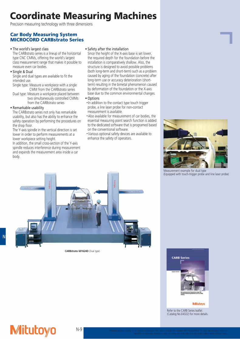
Car Body Measuring SystemMICROCORD CARBstrato Series
•Theworld'slargestclass The CARBstrato series is a lineup of the horizontal
type CNC CMMs, offering the world's largest class measurement range that makes it possible to measure even car bodies.
•Single&Dual Single and dual types are available to fit the
intended use. Single type: Measure a workpiece with a single
CMM from the CARBstrato series Dual type: Measure a workpiece placed between
two simultaneously controlled CMMs from the CARBstrato series
•Remarkableusability The CARBstrato series not only has remarkable
usability, but also has the ability to enhance the safety operation by performing the procedures on the shop floor.
The Y-axis spindle in the vertical direction is set lower in order to perform measurements at a lower workpiece setting height.
In addition, the small cross-section of the Y-axis spindle reduces interference during measurement and expands the measurement area inside a car body.
•Safetyaftertheinstallation Since the height of the X-axis base is set lower,
the required depth for the foundation before the installation is comparatively shallow. Also, the structure is designed to avoid possible problems (both long-term and short-term) such as a problem caused by aging of the foundation (concrete) after long-term use or accuracy deterioration (short-term) resulting in the bimetal phenomenon caused by deformation of the foundation or the X-axis base due to the common environmental changes.
•Options ・In addition to the contact type touch trigger
probe, a line laser probe for non-contact measurement is available.
・Also available for measurement of car bodies, the essential measuring point search function is added to the dedicated software that is programed based on the conventional software.
・Various optional safety devices are available to enhance the safety of operators.
Measurement example for dual type (Equipped with touch-trigger probe and line laser probe)
CARBstrato 601624D (Dual type)
Refer to the CARB Series leaflet (Catalog No.E4322) for more details.

N-10
N
Mitutoyo operates a policy of continuous improvement that aims to provide the customer with the benefit of the latest technological advances.Therefore the company reserves the right to change any or all aspects of any product specification without notice.
Car Body Measuring SystemMICROCORD CARBapex Series
•Theworld'slargestclass The CARBapex series is a lineup of cost-effective
horizontal type, large CNC CMMs, and offers the world's largest class measurement range that makes it possible to measure even car bodies.
•Single&Dual Single and dual types are available to fit the
intended use. Single type: Measure a workpiece with a single
CMM from the CARBstrato series Dual type: Measure a workpiece placed between
two simultaneously controlled CMMs from the CARBstrato series
Also, since the height of the X-axis base of both the single type and the dual type is set lower, the required depth for the foundation before the installation is comparatively shallow.
•Remarkableusability The CARBapex series not only has remarkable
usability, but also has the ability to enhance the safety operation by performing the procedures on the shop floor.
The Y-axis spindle in the vertical direction is set lower in order to perform measurements at a lower workpiece setting height.
In addition, the small cross-section of the Y-axis spindle reduces interference during measurement and expands the measurement area inside a car body.
•Options ・In addition to the contact type touch trigger
probe, a line laser probe for non-contact measurement is available.
・Also available for measurement of car bodies, the essential measuring point search function is added to the dedicated software that is programed based on the conventional software.
・Various optional safety devices are available to enhance the safety of operators.
CARBapex 601624 (single type)
Refer to the CARB Series leaflet (Catalog No.E4322) for more details.

N-11
N
Coordinate Measuring MachinesPrecision measuring technology with three dimensions
Mitutoyo operates a policy of continuous improvement that aims to provide the customer with the benefit of the latest technological advances.Therefore the company reserves the right to change any or all aspects of any product specification without notice.
Refer to the MACH Series leaflet (Catalog No.E16010) for more details.
In-line Type CNC CMMMICROCORD MACH-3A 653
•In-linetypeCNCCMM(Horizontaltype) Incorporating the CMM controller and the host computer in the main unit results in a compact spacing
saving footprint for the shop floor. This series is designed for 24 hour operation resulting in stable operation and remarkable durability.
In-line Type CNC CMMMICROCORD MACH-V9106
The MACH-V has been refined and has evolved over time maximizing machining operations by performing in-line or near-line, high speed coordinate measuring in concurrence with CNC machine tools. These high throughput machines can be incorporated within the manufacturing line and can provide pre/post machining feedback to your machine tool for machining adjustments.
MACH-V 9106
MACH-3A 653
SPECIFICATIONS
SPECIFICATIONS
Model Items MACH-3A 653
Measuring rangeX axis 600mmY axis 500mmZ axis 280mm
Measuring speed 1 to 30mm/s (for TP7M) Maximum drive speed each axis 8 to 700mm/s; all axes 1212mm/sMaximum drive acceleration each axis 6860mm/s2 ; all axes 11882mm/s2
Accuracy*19 to 21ºC MPEE = 2.5+3.5L/1000μm 5 to 40ºC MPEE = 3.9+6.5L/1000μm
* TP7M (Stylus: ø4×20mm) is used. L: measured length (mm). For information about guaranteed accuracy within a temperature range other than 5 to 40°C, contact your local Mitutoyo sales office.
Guaranteed accuracy temperature for MACH-3A 653
Guaranteed accuracy temperature for MACH-V9106
Temperature environment
Accuracy assurance conditions
Range 5 to 40ºCRate of change
2.0K or less/1hr10.0K or less/24hrs
GradientVertical 1.0K or less/1m Horizontal 1.0K or less/1m
Temperature environment
Accuracy assurance conditions
Range 5 to 35ºCRate of change
2.0K or less/1hr10.0K or less/24hr
GradientVertical 1.0K or less/1m Horizontal 1.0K or less/1m
Model Items MACH-V9106
Measuring rangeX axis 900mmY axis 1000mmZ axis 600mm
Measuring speed 1 to 20mm/s (for TP7M)Maximum drive speed each axis 8 to 500mm/s; all axes 866mm/sMaximum drive acceleration each axis 4900mm/s2 ; all axes 8480mm/s2
Accuracy*19 to 21ºC MPEE = 2.5+3.5L/1000μm 5 to 40ºC MPEE = 3.6+5.8L/1000μm
* TP7M (Stylus: ø4×20mm) is used. L: measured length (mm). For information about guaranteed accuracy within a temperature range other than 5 to 35°C, contact your local Mitutoyo sales office.
*The indexing table is optional.

N-12
N
Mitutoyo operates a policy of continuous improvement that aims to provide the customer with the benefit of the latest technological advances.Therefore the company reserves the right to change any or all aspects of any product specification without notice.
•Incorporatingameasuringinstrumentinaproductionline allows earlier detection of defectives.
•Themanagementofabsolutedimensionsfacilitatesfeedback to the processing machine.
•Alsoapplicabletodiversifiedsmall-quantityproduction.
•Atraceablequalitycontrolsystemcanbebuilt.•High-accuracymeasurementcanbeperformed.
Guaranteed accuracy temperature for MACH Ko-ga-me
Temperature environment
Range
Without thermal compensation 19 to 21ºC
With compensation 10 to 35ºC
Rate of change
Without thermal compensation 2.0K or less/8hr
With compensation 2.0K or less/1hr
Gradient
Without thermal compensation
1.0K or less/1m (in horizontal/vertical
direction)
With compensation
1.0K or less/1m (in horizontal/vertical
direction)
Agile Measuring SystemMACH Ko-ga-me
•Canbeusedinstandaloneapplicationsorintegrated into work cells.
•Ifrequired,thesystemcanmeasureworkpiece features that exceed the Ko-ga-me’s X stroke by mounting the workpiece, or the Ko-ga-me, on an auxiliary X axis.
•Idealforinspectionoflargeorsmallworkpieces and offers a wide choice of measuring probes including touch-trigger, optical and scanning types. (Note: Probe choice may be restricted, depending on the application.)
SPECIFICATIONS
In-line measurement
Model KGM884-3V KGM12124-3V KGM888-3V KGM12128-3V
Measuring range (mm) 80×80×40(85×85×45)*1
120×120×40(125×125×45)*1
80×80×80(85×85×85)*1
120×120×80(125×125×85)*1
Measuring accuracy (μm)
19-21ºC (2.0+5.0L/1000)15-25ºC (2.3+5.7L/1000)*2
10-30ºC (2.7+6.5L/1000)*2
10-35ºC (3.0+7.2L/1000)*2
Drive speed (mm/sec) Max. 200 (1 axis) / Max. 340 (Composition of 3 axes)Drive acceleration (mm/sec2) Max. 3900 (1 axis) / Max. 6750 (Composition of 3 axes)
*1 Values in parentheses indicate the range within which the center of a touch-probe stylus contact point can move.*2 Measuring accuracy when the thermal compensation function is used
Standalone systemWorkpiece measurement within Ko-ga-me's measuring volume
Moving-head system
*1 The stand is option.*2 An auxiliary X-axis system shall be provided by the customer..
Auxiliary X axis*2MACH Ko-ga-me
MACH Ko-ga-me
The workpiece is fixed in position.
Stand*1
The workpiece is fixed and the Ko-ga-me moves on an auxiliary X axis supported by the frame.

N-13
N
Coordinate Measuring MachinesPrecision measuring technology with three dimensions
Mitutoyo operates a policy of continuous improvement that aims to provide the customer with the benefit of the latest technological advances.Therefore the company reserves the right to change any or all aspects of any product specification without notice.
Manual Type CMMMICROCORD Crysta-Plus M Series
Crysta-Plus M7106Crysta-Plus M443 with MCOSMOS
Refer to the Crysta-Plus M Series leaflet (Catalog No.E4332) for more details.
•ManualfloatingtypeCMMsdevelopedinquestfor high-accuracy, low-cost and easy operation. The Crysta-Plus M is suitable to measure a wide range of applications from a simple dimension to complex form.
•ThescalesystemsonMitutoyohigh-precisionmodels utilizes a high-performance linear encoder (manufactured by Mitutoyo), for detecting axis position. In addition, various technologies have been utilized in the structure, part processing, and assembly to provide high accuracy measurement.
•TheCrysta-PlusM700serieshasalargemainunit,and is equipped with a mobile clamp so that one-touch clamping on each axis can be performed by hand. Continuous fine feed over the entire measuring range can be performed.
•Crystahigh-precisionseriesCMM'sareequippedwith temperature compensation and therefore do not require a temperature controlled room. Accuracy is guaranteed within the range of 15 to 30°C.
•Availableoptionsincludetheauto-levelingairspring vibration isolator and the illuminator unit for the probe.
Crysta-Plus M574 with MCOSMOS

N-14
N
Mitutoyo operates a policy of continuous improvement that aims to provide the customer with the benefit of the latest technological advances.Therefore the company reserves the right to change any or all aspects of any product specification without notice.
SPECIFICATIONSModel
Items Crysta-Plus M443 Crysta-Plus M544 Crysta-Plus M574 Crysta-Plus M776 Crysta-Plus M7106
Measuring rangeX axis 400mm 500mm 700mmY axis 400mm 400mm 700mm 700mm 1000mmZ axis 300mm 400mm 600mm
Resolution 0.0005mm (0.5μm)Accuracy *1,*2
(at 20°C)Measuring error (E) E= (3.0+4L/1000) *3μm E= (3.5+4L/1000) *3μm E= (4.5+4.5L/1000) *3μmProbing error (R) 4.0μm 4.0μm 5.0μm
Guide method Air bearings on each axisClamping of each axis One-touch air clamp (mobile clamp switch Box)Fine feed of each axis Continuous fine feed over the entire measuring rangeMaximum measurable height 480mm 595mm 800mmMaximum table loading 180kg 180kg 500kg 800kgMass (including stand) 410kg 512kg 646kg 1560kg 1800kgZ-axis balancing method Counterweight
Air supplyPressure 0.35MPa (air source: 0.5 to 0.9MPa) 0.4MPa (air source: 0.5 to 0.9MPa)Consumption 50L/min under normal conditions (air source: 100L/min)
*1 According to ISO 10360-2 methods*2 When using the touch-trigger probe MH20i/ MH20/ TP20 and stylus (L10mm)*3 L = measured length (mm)Note: While the appearance of the natural stone measuring table varies according to the source, the high stability for which this material is known can always be relied upon.
Guaranteed accuracy temperature limits for CRYSTA-Plus M Series
Without thermal compensation 19 to 21ºC (Temperature change: 2.0K or less/8hrs)
With compensation
Range 15 to 35ºC
Rate of change2.0K or less /1hrs5.0K or less /24hrs
Gradient 1.0K or less /1m
Data Processing UnitQM-Data300
QM-Data300 is a dedicated control data processing unit that can be used with manual floating CMM's.• The QM-Data 300 has a simple measurement
function that enables 3D measurement without standard coordinates, just like measurement using a gage.
• On screen icons for performance selection along with instructions for entering data.
Example of mounting on Crysta-Plus M443

N-15
Coordinate Measuring MachinesPrecision measuring technology with three dimensions
Mitutoyo operates a policy of continuous improvement that aims to provide the customer with the benefit of the latest technological advances.Therefore the company reserves the right to change any or all aspects of any product specification without notice.
N
Scanning probe
Non-contact probe
Probe for roughness measurement
MPP-310Q/MPP-310 SP80High accuracy scanning probe (long stylus supported)A highly accurate and long stylus up to 500mm (both horizontally and vertically) can be installed. This ultra-high precision scanning probe allows data collection by the scanning measurement, the ultra-high precision point measurement and the center alignment point measurement.
SP25MCompact high accuracy type scanning probeThis compact, high accuracy type scanning probe has ø25mm outside diameter. The multi-functioning scanning probe performs data collection by the scanning measurement, the ultra-high precision point measurement and the center alignment point measurement. The probe can be attached to a probe head (PH10M/10MQ) to automatically change the orientation allowing for more flexible measurements.
Ultra-high accuracy and low measuring force scanning probeThe ultra-high precision scanning probe adapts for directional movement. The compact size of this probe is ideal for low measuring force and high speed scanning. Data collection can be performed by the scanning measurement, ultra-high precision point measurement and the center alignment measurement.
MPP-10
REVO
Probe for effective thread-depth measurementThis is the only probe in the world that is dedicated for effective screw depth used with a CNC CMM. The probe can also attach to the probe head (PH10M/10MQ) to changing the orientation to measure bores in various directions.
High speed 5-axis scanning headThis high speed scanning head delivers high accuracy measurement while delivering high-throughput. The use of a stylus increases flexibility up to 500mm and makes measuring 5-axis with simultaneous control and non-step indexing possible.
CF20
SurfaceMeasure606 SurfaceMeasure606T
Centering microscope for CMMsThis centering microscope can measure small holes or elastic bodies that are very difficult to measure using a contact type probe such as the touch-trigger probe. A CMM can be used as a large microscope.
QVPQUICK VISION probe This CNC CMM Quick Vision Probe utilizes Mitutoyo's technology in a vision measuring machine for totally-automated video measurement.
SurfaceMeasure606/606T/1010
SURFTEST PROBE
Non-contact type laser probeThis compact, high accuracy, non-contact type laser probe is designed for use with CNC CMMs. The scanning probe automatically adjusts to workpiece surface characteristics to deliver highly efficient measurements. Automatic laser intensity and camera sensitivity adjust according to the environment and the workpiece material, for simpler and more comfortable laser scanning. Improvements to the probe have increased the measurement speed and accuracy without interference.
Probe for surface roughness measurementMounting of this probe on a CMM enables surface roughness measurement and analysis to be included in fully automatic CNC measurement cycles. This probe is compatible with the automatic probe changer, and therefore can be automatically replaced with another type of probe for 3D coordinate measurement. A wide variety of roughness analyses can be performed using the dedicated evaluation program.

N-16Mitutoyo operates a policy of continuous improvement that aims to provide the customer with the benefit of the latest technological advances.Therefore the company reserves the right to change any or all aspects of any product specification without notice.
N
Refer to the Probes for Coordinate Measuring Machines leaflet (Catalog No.E16005) for more details.
Touch-trigger probe
Probe headPH10M/10MQMotorized probe head The probe allows automatic control of positioning (up to 720 directions) of the mounted probe. It is possible to mount not only a touch-trigger probe but also any scanning probe, vision probe, laser probe, screw thread depth probe, etc. Auto-changing is available (optional).
▲ Mounting example of touch-trigger probe
TP7M
High accuracy touch-trigger probeThis high-accuracy touch-trigger probe has high repetitive accuracy of 2σ≦ 0.25μm. A long stylus up to 180mm can be installed.
TP200
Compact high-accuracy touch-trigger probe This compact, high accuracy, touch-trigger probe is ø13.5mm outside diameter.Styli auto-changing (optional) is supported.
TP20
Compact touch-trigger probe This compact, touch-trigger probe is ø13.5mm outside diameter. Styli auto-changing (optional) is supported when mounted on a CNC CMM.
PH1
MH20
UMAP-CMM PH20
Touch-trigger probe equipped with manual probe head This touch-trigger probe equipped with manual probe head is designed for use with manual CMMs. The probe head section can be manually positioned to the desired orientation.
Micro touch probe A stylus with an ultra-small diameter of ø0.1mm or ø0.3mm can be used.Measurement of miniscule form and dimensions from practically any direction is possible by mounting on the PH10MQ.
5-axis control touch-trigger system Thanks to the unique "head touches", it is possible to measure by movement of the probe head instead of coordinate measurement. Also, measuring time can significantly be shortened by means of 5-axis concurrent control and stepless positioning angle.
MH20iTouch-trigger probe equipped with manual probe head This touch-trigger probe equipped with manual probe head is designed for use with manual CMMs. The probe head section may be manually indexed to 168 positions.
MIHMounting example of touch-trigger probe This probe head allows manual positioning (up to 720 directions) of the mounted probe (for TP200/ TP20/ TP2-5W). A probe extension up to 300mm can be attached.
▲ Mounting example of touch-trigger probe
Mounting example of touch-trigger probe This manual probe head is designed for use with the TP200/ TP20.It is possible to manually change positioning of the attached probe to the desired orientation.
▲ Mounting example of touch-trigger probe

N-17
Coordinate Measuring MachinesPrecision measuring technology with three dimensions
Mitutoyo operates a policy of continuous improvement that aims to provide the customer with the benefit of the latest technological advances.Therefore the company reserves the right to change any or all aspects of any product specification without notice.
N
This is the basic software for dimension measurement. The enhanced graphic functionality allows real time drawing of the measurement result, and the best-fit function, previously optional, and even the geometrical deviation drawing function are now provided as standard.
GEOPAK [General purpose measurement program]
The function of analysis software as used for roundness measuring machines is now available on MCOSMOS. As well as roundness and cylindricity evaluation, various filters are also available.
ROUNDPAK-CMM
This program is used for minutely analyzing two-dimensional curved lines captured by SCANPAK.
FORMPAK-CMM [Analysis program]
SURFPAK-SP [Analysis program]
This software is used for on-/off-line teaching. The interference check function is also added so that programming error when off-line can be prevented. In addition to IGES, SAT, VDAFS (standard function) as CAD data that can be imported, CATIA V4/V5, PARASOLID, PRO/E, STEP, etc. are supported. (optional)
CAT1000P [On-/Off-line teaching program]
MCOSMOS software modules
Software for Manual / CNC Coordinate Measuring MachinesMCOSMOS •MCOSMOSisthedataprocessingprogram
family for the CMM that runs on Windows XP.
•Itisunnecessarytolearnanyspecialcodesince measurement can be performed by selecting the icons or the pull-down menu to select functions in the same manner as for Windows OS operation.
•TherearetwotypesofMCOSMOSprograms: one for manual CMMs and one for CNC CMMs. Therefore, it is possible to perform measurement with a consistent operation method starting from manual measurement to CNC measurement.
•Itispossibletodisplayelementsobtainedby measurement/computation in graphical format and to recall any particular element just by clicking the respective graphic.
•Thescreenlayoutcanbecustomizedasneeded since it is easy to turn each screen on/off and to freely edit the display size/position.
GEOPAK CAT1000P CAT1000S SCANPAKMCOSMOS-1 ○ ̶ ̶ ̶MCOSMOS-2 ○ ○ ○ ̶MCOSMOS-3 ○ ○ ○ ○
Refer to the MCOSMOS Software for CNC Coordinate Measuring Machines leaflet (Catalog No.E16008) for more details.Refer to the MCOSMOS Software for Manual Coordinate Measuring Machines leaflet (Catalog No.E4180) for more details.
This is a software program as used only for the roughness probe "SURFTEST PROBE" for a CMM. With this program, surface roughness analysis conforming to standards such as ISO, JIS, ANSI, and VDA are available. Cooperation with MCOSMOS enables full-automatic dimensional measurement and surface roughness measurement.

N-18Mitutoyo operates a policy of continuous improvement that aims to provide the customer with the benefit of the latest technological advances.Therefore the company reserves the right to change any or all aspects of any product specification without notice.
N
This software is used for free-form surface evaluation and on-/off-line teaching. It is possible to display measurement results on CAD data in various ways.
CAT1000S [Curved surface evaluation program]
MAFIS Express [Blade measurement/Evaluation program]
This is a program for evaluation of involute gear teeth obtained from CNC CMMs, and tooth profile or tooth trace based on cylindrical gear measurement data.
GEARPAK-Cylindrical [Gear evaluation program]
This software enables measurement/evaluation of two-dimensional sectional contours. The data output function to CAD, etc. that had been optional before is featured.
SCANPAK [Contour measurement program]
This software is used for evaluation of sectional contours of blades to be used in jet engines for aircraft.
MAFIS [Blade evaluation program]
This is a program for evaluation of tooth form, tooth trace, etc., based on worm measurement data obtained from CNC CMMs.
GEARPAK-Worm [Gear evaluation program]
This is a program for evaluation of tooth form, pitch error, etc., based on measurement data from bevel or hypoid gears obtained by CNC CMM.
GEARPAK-Bevel/Hypoid[Gear production support/evaluation program]
[Result drawing]
[Result drawing]
This software program enables creation of measurement programs and measurement and analysis of blades and blisks. A part program for measurement can be automatically created just by selecting required contents and evaluation conditions. The measurement results will be displayed in a report including 2D graphics.

N-19
Coordinate Measuring MachinesPrecision measuring technology with three dimensions
Mitutoyo operates a policy of continuous improvement that aims to provide the customer with the benefit of the latest technological advances.Therefore the company reserves the right to change any or all aspects of any product specification without notice.
N
Software for Manual/CNC Coordinate Measuring MachinesMSURF
Note: If not using ACR3, probe replacement is performed manually.
A scanning path can be created just by defining a scanning start point, a scanning length, and a scanning width.
•Specifyingthe3pointscanbesimplyperformedby operating the joystick while watching the camera view.
•Whenapointgroupormasterdataexistsonthescreen, the 3 points can be defined by selecting the data using the mouse. This is useful for creation of the measuring path by simulation and specification for re-measurement of data left behind, which helps reduce measuring man-hours.
•Operatingjoystickbuttonsenablesconfigurationand execution of a scanning path, and registration to or deletion from a macro. Capability of measurement without using a PC has significantly improved operational efficiency, especially for large-sized CMMs.
MSURF-S can be started from MCOSMOS.
•AworkcoordinatesystemcreatedwithMCOSMOS can be used with MSURF-S. Therefore, fully automatic measurement combined with "Contact Measurement/Non-Contact Measurement" can be performed.
Scanning paths can be registered as a measurement macro.•Themeasurementconditionsofameasurement
macro can be partly or wholly changed by the override function.
•Thesub-macrofunctioniseffectiveformeasuringmultiple, identical workpieces.
•Atrialcalculationofmeasurementmacroexecutiontime is made based on the measurement conditions and the specifications of the CMM.
* Functions added from MSURF V2.011 or later
•MSURFisasoftwareprogramthatenables users to perform operations from measurement to evaluation on the same platform when the non-contact line laser probe, SurfaceMeasure, is used.
Three types of software are provided according to the task.
MSURF-S: Calculates point cloud data measured by CNC CMM with SurfaceMeasure.
It generates scanning paths by defining the scanning start position, length, and width.
MSURF-I: Conducts analysis or comparison verification of measured point cloud data in reference to nominal data (supporting CAD data import).
MSURF-G: Primarily creates part programs (measurement procedure programs) using CAD data.
Scanning: MSURF-S
N-20Mitutoyo operates a policy of continuous improvement that aims to provide the customer with the benefit of the latest technological advances.Therefore the company reserves the right to change any or all aspects of any product specification without notice.
N
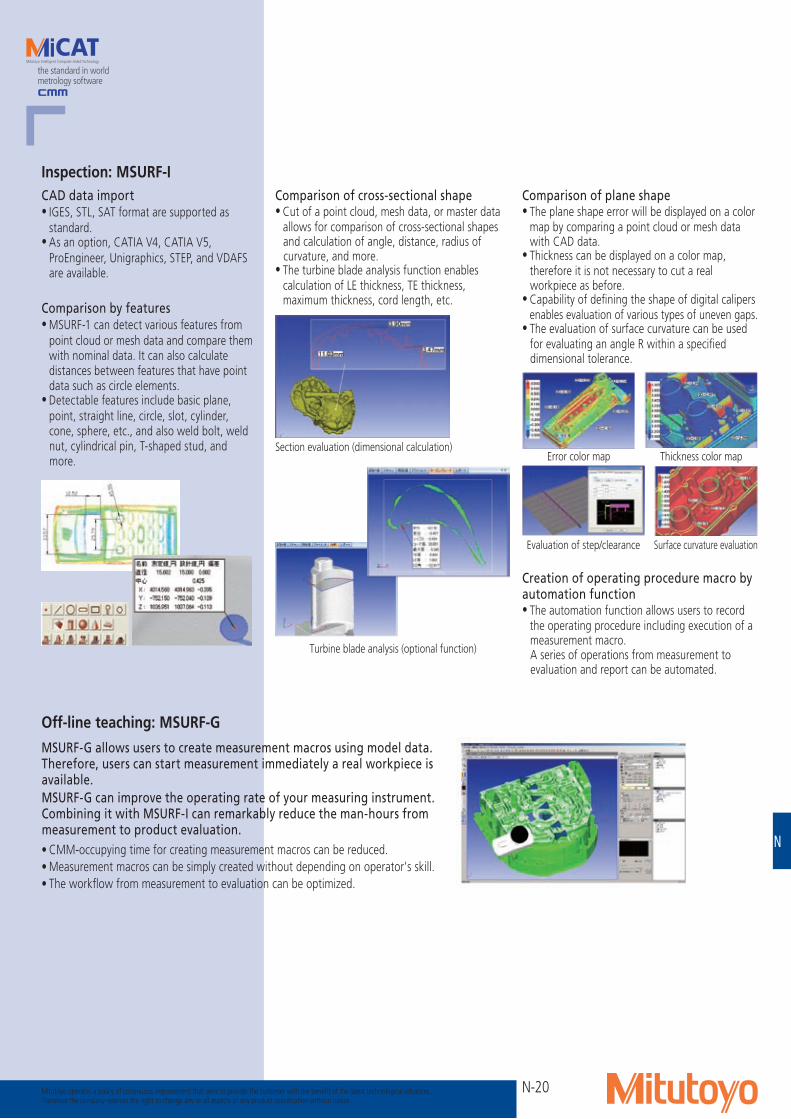
Error color map Thickness color map
Evaluation of step/clearance
Section evaluation (dimensional calculation)
Turbine blade analysis (optional function)
Surface curvature evaluation
CAD data import•IGES, STL, SAT format are supported as
standard.•As an option, CATIA V4, CATIA V5,
ProEngineer, Unigraphics, STEP, and VDAFS are available.
Comparison of cross-sectional shape•Cut of a point cloud, mesh data, or master data
allows for comparison of cross-sectional shapes and calculation of angle, distance, radius of curvature, and more.
•The turbine blade analysis function enables calculation of LE thickness, TE thickness, maximum thickness, cord length, etc.
Creation of operating procedure macro by automation function•The automation function allows users to record
the operating procedure including execution of a measurement macro.
A series of operations from measurement to evaluation and report can be automated.
Comparison by features•MSURF-1 can detect various features from
point cloud or mesh data and compare them with nominal data. It can also calculate distances between features that have point data such as circle elements.
•Detectable features include basic plane, point, straight line, circle, slot, cylinder, cone, sphere, etc., and also weld bolt, weld nut, cylindrical pin, T-shaped stud, and more.
Comparison of plane shape•The plane shape error will be displayed on a color
map by comparing a point cloud or mesh data with CAD data.
•Thickness can be displayed on a color map, therefore it is not necessary to cut a real workpiece as before.
•Capability of defining the shape of digital calipers enables evaluation of various types of uneven gaps.
•The evaluation of surface curvature can be used for evaluating an angle R within a specified dimensional tolerance.
MSURF-G allows users to create measurement macros using model data. Therefore, users can start measurement immediately a real workpiece is available.MSURF-G can improve the operating rate of your measuring instrument. Combining it with MSURF-I can remarkably reduce the man-hours from measurement to product evaluation.•CMM-occupyingtimeforcreatingmeasurementmacroscanbereduced.•Measurementmacroscanbesimplycreatedwithoutdependingonoperator'sskill.•Theworkflowfrommeasurementtoevaluationcanbeoptimized.
Inspection: MSURF-I
Off-line teaching: MSURF-G

N-21
Coordinate Measuring MachinesPrecision measuring technology with three dimensions
Mitutoyo operates a policy of continuous improvement that aims to provide the customer with the benefit of the latest technological advances.Therefore the company reserves the right to change any or all aspects of any product specification without notice.
N
Multi-axis Portable Coordinate Measuring SystemSpinArm-Apex
SPECIFICATIONS
SpinArm-Apex is a fully articulated coordinate measuring system featuring a wide range of measure-ment. The highly portable design of SpinArm-Apex enables the system to be positioned at any point near the workpiece.•Enablesmeasurementofworkpiecesof
complex shape in any direction.•Portabilityenablesthemeasurementsystem
to be positioned close to the workpiece.•Brake mechanism enhances the usability greatly.•Counterbalanceforeasieroperation.•Supportsbothnon-contactlinelaserprobes
and contact probes concurrently.
* Not for use in, or export to, to the United States of America.
SpinArm-Apex 366S SpinArm-Apex 367S
6-axis modelModel No. SpinArm-Apex 186S SpinArm-Apex 246S SpinArm-Apex 306S SpinArm-Apex 366SMeasuring envelope (Probe reaching diameter)*1 1800 mm 2400 mm 3000 mm 3600 mm
Repeatability*2 ± 0.040 mm ± 0.050 mm ± 0.080 mm ± 0.100 mmAccuracy (Arm type)*2 ± 0.055 mm ± 0.065 mm ± 0.100 mm ± 0.135 mmMass (main unit) 14.5 kg 14.7 kg 15.2 kg 15.6 kg
7-axis modelModel No. SpinArm-Apex 247S SpinArm-Apex 307S SpinArm-Apex 367SMeasuring envelope (Probe reaching diameter)*1 2400 mm 3000 mm 3600 mm
Repeatability*2 ± 0.055 mm ± 0.090 mm ± 0.110 mmAccuracy (Arm type)*2 ± 0.080 mm ± 0.135 mm ± 0.165 mmMass (main unit) 15.1 kg 15.6 kg 16.0 kg*1 Measurement range is expressed as a diameter value at the maximum reach using software with the Sø10mm standard probe mounted.*2 According to Mitutoyo’ s acceptance procedure. The accuracy guaranteed value above is determined when MS5-5R11G probe is mounted.Note: Guaranteed accuracy temperature: 20ºC ± 4ºC (temperature gradient: 1.5 K per hour) Refer to the SpinArm-Apex Series leaflet
(Catalog No.E16006) for more details.

N-22Mitutoyo operates a policy of continuous improvement that aims to provide the customer with the benefit of the latest technological advances.Therefore the company reserves the right to change any or all aspects of any product specification without notice.
N
Regarding the performance assessment method of coordinate measuring machines, JIS was revised in 2003. In the revised JIS, the standards for scanning measurement and rotary tables have been added to the conventional test items. Also, the concept of "uncertainty" has been incorporated into the latest JIS. At that point in 2003 the four items in Table 1 were standardized.
Figure 2 Target points on standard sphere for determining the Maximum Permissible Probing Error
Table 1 JIS B 7440 (2003) Series
MPEE= A+ L/K≦ BMPEE= A+ L/KMPEE= B
A: Constant (μm) specified by the manufacturerK: Dimensionless constant specified by the manufacturerL: Measured length (mm)B: Upper limit value (μm) specified by the manufacturer
■ Performance Assessment Method of Coordinate Measuring Machines
The test procedure under this standard is that a coordinate measuring machine (CMM) is made to perform a series of measurements on five different test lengths in each of seven directions, as shown in Figure 1, to produce a set of 35 measurements. This sequence is then repeated twice to produce 105 measurements in all. If these results, including allowances for the uncertainty of measurement, are equal to or less than the values specified by the manufacturer then the performance of the CMM has been proved to meet its specification. The standard allows up to five measurements to exceed the specified value (two NG results among 3-time measurements in the same position are not allowed). If this is the case, additional 10-times measurements for the relevant position are performed. If all the 10 results, including the uncertainty allowance, are within the specified value, the CMM is assumed to pass the test. The uncertainties to be considered in determining the maximum permissible measuring error are those concerning calibration and alignment methods used with the particular material standards of length involved with the test. (The values obtained by adding an extended uncertainty combining the above two uncertainties to all test results must be less than the specified value.) The result of the test may be expressed in any of the following three forms (unit: μm).
■Maximum Permissible Measuring Error MPEE [JIS B 7440-2 (2003)]
The test procedure under this standard is that a probe is used to measure defined target points on a standard sphere (25 points, as in Figure 2) and the result used to calculate the position of the sphere center by a least squares method. Then the distance R from the sphere center for each of the 25 measurement points is calculated, and the radius difference Rmax - Rmin is computed. An extended uncertainty that combines the uncertainty of the stylus tip shape and that of the standard test sphere is added to the radius difference. If this final calculated value is equal to or less than the specified value, the probe has passed the test.
■Maximum Permissible Probing Error MPE P [JIS B 7440-2 (2003)]
This is the accuracy standard for a CMM if equipped with a scanning probe. Scanning probing error was standardized in JIS B 7440-2 (2003) for the first time. The test procedure under this standard is to perform a scanning measurement of 4 planes on the standard sphere and then, for the least squares sphere center calculated using all the measurement points, calculate the range (dimension ‘A’ in Figure 3) in which all measurement points exist. Based on the least squares sphere center calculated above, calculate the distance between the calibrated standard sphere radius and the maximum measurement point or minimum measurement point, and take the larger distance (dimension ’B’ in Figure 3). Add an extended uncertainty that combines the uncertainty of the stylus tip shape and the uncertainty of the standard test sphere shape to each A and B dimension. If both calculated values are less than the specified values, this scanning probe test is passed.
■Maximum Permissible Scanning Probing Error MPE THP [JIS B 7440-4 (2003)]
The test procedure under this standard is to place two standard spheres on the rotary table as shown in Figure 4. Rotate the rotary table to a total of 15 positions including 0˚, 7 positions in the plus (+) direction, and 7 positions in the minus (-) direction and measure the center coordinates of the two spheres in each position. Then, add the uncertainty of the standard sphere shape to each variation (range) of radial direction elements, connecting direction elements, and rotational axis direction elements of the two standard sphere center coordinates. If these calculated values are less than the specified values, the evaluation test is passed.
22.5゜
22.5゜a22.5゜
22.5゜
22.5゜
Figure 1 Typical test measurement directions within the CMM measuring volume
Figure 4 Evaluation of a CMM with a rotary table
Item JISStandardNo. Yearofissue1 Terms JIS B 7440-1 (2003) 2003/4 2 Dimensional measurement JIS B 7440-2 (2003) 2003/4 3 Rotary table-equipped CMM JIS B 7440-3 (2003) 2003/4 4 Scanning measurement JIS B 7440-4 (2003) 2003/4
Figure 3 Target measurement planes for the maximum permissible scanning probing error and its evaluation concept
■Maximum Permissible Rotation Axis Radial-Direction Error MPE FR, Maximum Permissible Rotation Axis Connecting-Direction Error MPE FT, and Maximum Permissible Rotation Axis Axial-Direction Error MPE FA [JIS B 7440-3 (2003)]
Coordinate Measuring MachinesQuick Guide to Precision Measuring Instruments

N-23 Mitutoyo operates a policy of continuous improvement that aims to provide the customer with the benefit of the latest technological advances.Therefore the company reserves the right to change any or all aspects of any product specification without notice.
N
Regarding the performance assessment method of coordinate measuring machines, JIS was revised in 2003. In the revised JIS, the standards for scanning measurement and rotary tables have been added to the conventional test items. Also, the concept of "uncertainty" has been incorporated into the latest JIS. At that point in 2003 the four items in Table 1 were standardized.
Figure 2 Target points on standard sphere for determining the Maximum Permissible Probing Error
Table 1 JIS B 7440 (2003) Series
MPEE= A+ L/K≦ BMPEE= A+ L/KMPEE= B
A: Constant (μm) specified by the manufacturerK: Dimensionless constant specified by the manufacturerL: Measured length (mm)B: Upper limit value (μm) specified by the manufacturer
■ Performance Assessment Method of Coordinate Measuring Machines
The test procedure under this standard is that a coordinate measuring machine (CMM) is made to perform a series of measurements on five different test lengths in each of seven directions, as shown in Figure 1, to produce a set of 35 measurements. This sequence is then repeated twice to produce 105 measurements in all. If these results, including allowances for the uncertainty of measurement, are equal to or less than the values specified by the manufacturer then the performance of the CMM has been proved to meet its specification. The standard allows up to five measurements to exceed the specified value (two NG results among 3-time measurements in the same position are not allowed). If this is the case, additional 10-times measurements for the relevant position are performed. If all the 10 results, including the uncertainty allowance, are within the specified value, the CMM is assumed to pass the test. The uncertainties to be considered in determining the maximum permissible measuring error are those concerning calibration and alignment methods used with the particular material standards of length involved with the test. (The values obtained by adding an extended uncertainty combining the above two uncertainties to all test results must be less than the specified value.) The result of the test may be expressed in any of the following three forms (unit: μm).
■Maximum Permissible Measuring Error MPEE [JIS B 7440-2 (2003)]
The test procedure under this standard is that a probe is used to measure defined target points on a standard sphere (25 points, as in Figure 2) and the result used to calculate the position of the sphere center by a least squares method. Then the distance R from the sphere center for each of the 25 measurement points is calculated, and the radius difference Rmax - Rmin is computed. An extended uncertainty that combines the uncertainty of the stylus tip shape and that of the standard test sphere is added to the radius difference. If this final calculated value is equal to or less than the specified value, the probe has passed the test.
■Maximum Permissible Probing Error MPE P [JIS B 7440-2 (2003)]
This is the accuracy standard for a CMM if equipped with a scanning probe. Scanning probing error was standardized in JIS B 7440-2 (2003) for the first time. The test procedure under this standard is to perform a scanning measurement of 4 planes on the standard sphere and then, for the least squares sphere center calculated using all the measurement points, calculate the range (dimension ‘A’ in Figure 3) in which all measurement points exist. Based on the least squares sphere center calculated above, calculate the distance between the calibrated standard sphere radius and the maximum measurement point or minimum measurement point, and take the larger distance (dimension ’B’ in Figure 3). Add an extended uncertainty that combines the uncertainty of the stylus tip shape and the uncertainty of the standard test sphere shape to each A and B dimension. If both calculated values are less than the specified values, this scanning probe test is passed.
■Maximum Permissible Scanning Probing Error MPE THP [JIS B 7440-4 (2003)]
The test procedure under this standard is to place two standard spheres on the rotary table as shown in Figure 4. Rotate the rotary table to a total of 15 positions including 0˚, 7 positions in the plus (+) direction, and 7 positions in the minus (-) direction and measure the center coordinates of the two spheres in each position. Then, add the uncertainty of the standard sphere shape to each variation (range) of radial direction elements, connecting direction elements, and rotational axis direction elements of the two standard sphere center coordinates. If these calculated values are less than the specified values, the evaluation test is passed.
22.5゜
22.5゜a22.5゜
22.5゜
22.5゜
Figure 1 Typical test measurement directions within the CMM measuring volume
Figure 4 Evaluation of a CMM with a rotary table
Item JISStandardNo. Yearofissue1 Terms JIS B 7440-1 (2003) 2003/4 2 Dimensional measurement JIS B 7440-2 (2003) 2003/4 3 Rotary table-equipped CMM JIS B 7440-3 (2003) 2003/4 4 Scanning measurement JIS B 7440-4 (2003) 2003/4
Figure 3 Target measurement planes for the maximum permissible scanning probing error and its evaluation concept
■Maximum Permissible Rotation Axis Radial-Direction Error MPE FR, Maximum Permissible Rotation Axis Connecting-Direction Error MPE FT, and Maximum Permissible Rotation Axis Axial-Direction Error MPE FA [JIS B 7440-3 (2003)]
Coordinate Measuring MachinesQuick Guide to Precision Measuring Instruments

Mitutoyo operates a policy of continuous improvement that aims to provide the customer with the benefit of the latest technological advances.Therefore the company reserves the right to change any or all aspects of any product specification without notice.
N
N-24