newton iq cycler operator manual - fresenius medical care · 2015-06-16 · newton iq® cycler...
TRANSCRIPT

NEWTON IQ® CYCLER operator manual
�

P/N 470203 Rev. H i
NEWTON IQ® CYCLER OPERATOR MANUAL
Copyright 2000 - 2014, Fresenius Medical Care North America,
All Rights Reserved.
This document contains proprietary and confidential information of
Fresenius USA, Inc. d/b/a Fresenius Medical Care North America and its
affiliates (“Fresenius Medical Care”). The contents of this document may
not be disclosed to third parties, copied, or duplicated in any form, in whole
or in part, without the prior written permission of Fresenius Medical Care.
NEWTON IQ, stay•safe, and Safe-Lock, PD Plus and IQcard are trademarks
of Fresenius Medical Care Holdings, Inc. All other trademarks are the
property of their respective owners.
US Federal law restricts this device to sale only by or on the order of a
physician. Frequency, duration, and parameters of treatment are to be
determined by the prescribing physician.
Indications for use: the Fresenius NEWTON IQ Cycler is indicated for
acute and chronic peritoneal dialysis.

ii P/N 470203 Rev. H
TABLE OF CONTENTS
1. GETTING YOUR CYCLER READY .............................................................. 1
a. Receiving the Cycler .......................................................................................... 1
b. Setting-Up the Cycler ........................................................................................ 1
c. Cycler Stand Assembly Instructions .................................................................. 2
d. Cycler Control Unit Setup ................................................................................. 3
2. THE CYCLER FRONT PANEL ....................................................................... 7
3. TYPES OF THERAPY ...................................................................................... 9
a. PD Plus Therapy ................................................................................................ 9
b. Continuous Cycling Peritoneal Dialysis (CCPD) .............................................. 9
c. Intermittent Peritoneal Dialysis (IPD) .............................................................10
d. Tidal Peritoneal Dialysis (TPD) ......................................................................10
4. SETTING THE CYCLER DATE AND TIME ...............................................11
5. TREATMENT SETTINGS AND OPTIONS ..................................................12
a. Patient Weight (PT WEIGHT) ........................................................................13
b. Number of Fills (# FILLS)..............................................................................13
c. Number of Pauses (# PAUSES) ......................................................................13
d. Pause Volume (PAUSE VOL) ........................................................................14
e. CCPD Volume (CCPDVOL) ...........................................................................15
f. Last Fill Volume (LAST FILL) .......................................................................15
g. Total Volume (TOTAL VOL) ........................................................................16
h. Fill Time (FILL TIME) ...................................................................................16
i. Dwell Time (DWELL TIME) ..........................................................................16
j. Drain Time (DRAIN TIME) ............................................................................16
k. Sleep Time (SLEEP TIME) ............................................................................17
l. Data Sheet (DATA SHEET) ............................................................................17
m. Patient Data (PATIENT DATA) ...................................................................18
n. Fast Fill/Drain (FAST FILL/DRAIN) ............................................................18
o. Last Bag Alarm (LAST BAG ALARM) ........................................................19
p. Prewarm Bags (PREWARM BAGS) .............................................................20
q. RX Start Time (RX START TIME) ...............................................................20
r. Tidal Settings (TIDAL SETTINGS) ...............................................................21

P/N 470203 Rev. H iii
6. ADDITIONAL OPTIONS ...............................................................................22
a. Screen Blanking (SCREEN BLANKING) .....................................................23
b. Alarm Volume (ALARM VOLUME) .............................................................23
c. Alarm Pitch (ALARM PITCH) .......................................................................23
d. Language (LANGUAGE) ...............................................................................23
e. Allow > 3 Liters? (ALLOW>3 LITERS?) .....................................................24
f. Weight Units (WEIGHT UNITS) ...................................................................24
g. IQcard Used? (IQCARD USED?) ..................................................................24
h. Add Diurnal UF? (ADD DIURNAL UF?) .....................................................24
7. USING THE PRESCRIPTION UPLOAD FEATURE ...................................25
8. YOUR PERSONAL PRESCRIPTION ...........................................................26
9. GETTING READY FOR YOUR TREATMENT ...........................................27
a. Prepare cycler for use .......................................................................................27
b. Tubing Set-Up ..................................................................................................28
c. Connecting to the solution bags .......................................................................31
d. Tubing Flush and Prime ...................................................................................32
e. Connecting to the Cycler – Leave your mask on. ............................................34
10. THE TREATMENT .........................................................................................36
a. Treatment Phases (All Therapy Types) ...........................................................36
b. Using One PAUSE ...........................................................................................38
c. Using Multiple PAUSES .................................................................................40
d. Connecting to the Cycler after more than one Pause Exchange: .....................41
e. Interrupting the Treatment ...............................................................................42
f. Bypassing ..........................................................................................................43
g. Moving the cycler During Your Treatment .....................................................43
h. Completing the Treatment ...............................................................................44
11. DISCONNECTING FROM THE CYCLER ...................................................45
12. PATIENT DATA ENTRY FEATURE ............................................................46
13. SETTING UP FOR THE NEXT TREATMENT ............................................48
14. LOOKING AT YOUR TREATMENT RECORD ..........................................49

iv P/N 470203 Rev. H
a. Cycle (CYC) .....................................................................................................49
b. Fill (FILL) ........................................................................................................50
c. Drain (DRAIN) ................................................................................................50
d. Ultrafiltration (UF) ..........................................................................................50
e. Total Cycler Dwell Time .................................................................................52
15. ALARMS .........................................................................................................53
a. Both Cover Open..............................................................................................54
b. Cooling Alarm .................................................................................................55
c. Drain Alarm .....................................................................................................56
d. Emptying Alarm...............................................................................................57
e. Fill Alarm .........................................................................................................58
f. Interrupt Too Long ...........................................................................................59
g. IQcard Batt Dead .............................................................................................60
h. IQcard Batt Low ..............................................................................................60
i. IQcard Is In .......................................................................................................61
j. IQcard Not In ....................................................................................................62
k. IQcard Not Initialized ......................................................................................63
l. IQcard Write Protected .....................................................................................64
m. Last Bag Alarm ...............................................................................................65
n. Valve Cover Open............................................................................................65
o. Mid-Drain Alarm .............................................................................................66
p. Mid-Fill Alarm .................................................................................................68
q. Not Flushing Alarm .........................................................................................69
r. No Upload During Treatment ...........................................................................70
s. Overfill Alarm ..................................................................................................70
t. Place Bags on Scale ..........................................................................................71
u. Priming Alarm .................................................................................................72
v. Pump Error .......................................................................................................73
w. Pump Head Open ............................................................................................74
x. Pump Leak Alarm ............................................................................................74
y. Scale Alarm ......................................................................................................75
z. Scale Error ........................................................................................................76
aa. Take Bags off Scale ........................................................................................77
bb. Treatment Setting Corrupted .........................................................................78
cc. Warming Alarm ..............................................................................................79
dd. Zero Fill Volume Alarm ................................................................................80
16. ABANDON TREATMENT ALARMS ...........................................................82

P/N 470203 Rev. H v
17. IN THE EVENT OF A POWER FAILURE ....................................................84
18. DESCRIPTION ................................................................................................85
19. GLOSSARY OF TERMS ................................................................................86
20. SPECIFICATIONS ..........................................................................................87
21. MAINTENANCE .............................................................................................88
22. WARNINGS AND PRECAUTIONS ..............................................................89
23. LIMITED WARRANTY .................................................................................93

vi P/N 470203 Rev. H
THIS PAGE INTENTIONALLY LEFT BLANK

1
1. GETTING YOUR CYCLER READY
a. Receiving the Cycler
The Cycler is delivered to you at your home. Everything needed for the
Cycler is included in one box. It is best if you set up the Cycler Stand first.
Once the Cycler Stand is set up, the Cycler Control Unit, Manifold Holder
and Pump-to-Drain simply hook onto the Cycler Stand.
b. Setting-Up the Cycler
A complete list of Cycler parts needed for setup is as follows:
1. Operator Instructions
2. Newton IQ Procedure Card P/N 470210
3. Newton IQ Assembly Procedure Card P/N 470211
4. Stand Poles (upper pole and lower pole)
5. Cycler Stand Base
6. 2 Hitch Pins (locking pins)
7. Hanger Rod (for hanging Cycler Control Unit onto Cycler Stand)
8. 20-Liter Bag Organizer (used on top of the Cycler Heater/Scale)
9. Cycler Control Unit
10. Drain Hook (for Drain Bag)
11. Pump-to-Drain
12. Pump-to-Drain Hanger Bracket
13. Manifold holder (used on top of the cycler stand)
OPERATOR INSTRUCTIONS
NEWTON IQ CYCLER

2 P/N 470203 Rev. H
Lower
Hitch Pin
Lower
Pole
Cycler Stand Base
Upper
Hitch Pin
Upper
Pole
Hanger Rod
Hole for
Hanger Rod
Pump-to-Drain
Hanger Bracket
GETTING YOUR CYCLER READY (cont’d)
c. Cycler Stand Assembly Instructions
1. Place the Lower Pole into the Cycler Stand Base. Make
sure the holes in both the Lower Pole and the Cycler Stand
Base are lined up so that the Lower Hitch Pin will go through
both pieces to hold them together.
2. Press and hold the button on the end of the Lower Hitch
Pin to flatten the locking bearings. Push the Lower Hitch Pin
through the lined-up holes in the Lower Pole and the Cycler
Stand Base. Let go of the button. This locks the Lower
Hitch Pin in place.
3. Place the Upper Pole into the Lower Pole. Line up the
holes in both poles. Slide the Pump-to-Drain Hanger Bracket
over and down the Upper Pole. Line up the slot in the Pump-
to-Drain Hanger Bracket with the Upper and Lower Pole
holes and insert the Upper Hitch Pin through all three items.
4. Remove the Hanger Rod from the Cycler shipping box.
Push the Hanger Rod through the upper holes at the top of
the Upper Pole. The Hanger Rod should form a “T” with the
Upper Pole.
WARNING! The Cycler Stand could
potentially tip over and cause injury if a
Cycler and Stand is used in a tilted position
or if moved without appropriate care.
Never place objects under the Cycler Stand
wheels to level the stand!

3
GETTING YOUR CYCLER READY (cont’d)
d. Cycler Control Unit Setup
1. Pick up the Cycler by its bottom, front and back. Lift the Cycler out of
its shipping box.
CAUTION! Do not lift the Cycler by the Heater Tray/Scale. Doing this
may damage the Cycler Scale.
2. Remove the Cycler from its protective foam. There are two hooks on the
back of the Cycler. These hooks are used to hang the Cycler onto the
Cycler Stand.
3. Face the front of the Cycler Stand. Lift the Cycler and hook it on to the
Cycler Hanger Rod. The front of the Cycler should be facing towards the
front of the Cycler Stand when properly positioned.
Cycler Hooks
(Cycler hooks
onto the Cycler
Hanger Rod first,
then Manifold Holder
hangs on second.)
SIDE VIEW
Drain Hook
FRONT VIEW
Pump to Drain
Manifold Holder
(hangs outside
of Cycler hooks).
Make sure the Cycler Control
Unit is positioned over the long
legs of the base.
4 P/N 470203 Rev. H
GETTING YOUR CYCLER READY (cont’d)
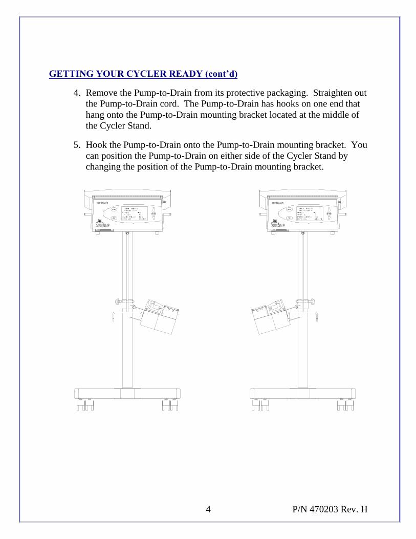
4. Remove the Pump-to-Drain from its protective packaging. Straighten out
the Pump-to-Drain cord. The Pump-to-Drain has hooks on one end that
hang onto the Pump-to-Drain mounting bracket located at the middle of
the Cycler Stand.
5. Hook the Pump-to-Drain onto the Pump-to-Drain mounting bracket. You
can position the Pump-to-Drain on either side of the Cycler Stand by
changing the position of the Pump-to-Drain mounting bracket.

5
GETTING YOUR CYCLER READY (cont’d)
6. Plug the Pump-to-Drain cable connector into the port labeled “Pump to
Drain” located on the back of the Cycler Control Unit.
7. Connect the Drain Hook to the Cycler Control Unit. The Drain Hook has
a rounded single hook at one end that hooks into an eyehook on the
bottom center of the Cycler Control Unit.
8. Connect the Manifold Holder to the Cycler stand. The Manifold Holder
has two rounded hooks that hook onto the hanger rod. The Manifold
Holder should extend above the cycler Heater Tray approximately 9
inches.
9. Place the clear plastic Bag Organizer on the cycler Control Unit
Heater/Scale. The Bag Organizer fits firmly onto the heater with its
edges up and the three cutouts for the Dialysis Solution outlet ports at the
back of the cycler.
Pump-to-Drain
plugs in here
Heater Switch
Heater Tray / Scale
Power
Switch
Electrical Plug
Cycler Pole
Hanger Rod
Manifold Holder

6 P/N 470203 Rev. H
GETTING YOUR CYCLER READY (cont’d)
WARNING! Check the Heater Tray and Bag Organizer to be sure they are
free of obstructions and do not touch the top of the Cycler Cabinet or the
Stand Pole (see figures below). Interference with the Heater Tray may
result in inaccurate weighing of Dialysis Solution. Check again when all
Solution bags are on the Scale.
Check and make sure the Manifold Holder does not come in contact with the
Bag Organizer, this may result in inaccurate weighing of Dialysis Solution.
NOTE: Save the Cycler shipping box and the foam inserts in case the
Cycler needs to be repacked.
CAUTION! The Newton IQ
Cycler is a computer controlled
electromechanical medical device. The Newton IQ Cycler
should be installed in an appropriate environment (indoors)
free from extremes of temperature and humidity. The
cycler should not be placed near sources of contamination
such as dirt, dust, or liquids. Failure to install the Newton
IQ Cycler according to these guidelines may result in
improper operation or early failure of the device or its
components.
CAUTION! Peritoneal dialysis solution should not be allowed to come
into contact with the Pump-to-Drain assembly. Peritoneal
dialysate leaves a dried salty residue that may be
electrically conductive, leading to electrical shorts or
corrosion of electrical or mechanical components.
Mechanical components such as the valve heads or the
cover may bind or corrode.

7
2. THE CYCLER FRONT PANEL
There is a display screen and five buttons on the front of the Cycler.
Messages for operating the Cycler are displayed on the screen. The five control
buttons work as follows:
The [START] button is used to move forward through the phases of a
treatment. After an alarm, pressing [START] continues the treatment.
During programming, pressing [START] takes you back to the
TREATMENT screens.
The [STOP] button mutes alarms. During the treatment set-up phase,
pressing [STOP] allows you to repeat a tubing flush or patient line prime.
During the treatment, pressing [STOP] interrupts the treatment.
The [SELECT] button takes you to the SETTINGS screen. A programming
cursor (in the shape of an arrow) is located on the SETTINGS screen,
between the treatment Setting and the Setting’s value. The cursor normally
points to the left towards the Settings. There are two ways to change a
Setting as follows:
1. For a Setting having only two values (for example, “YES” or “NO”,
or “ON” or “OFF”), use the [UP] or [DOWN] arrows to move the
cursor on the screen to the Setting that needs to be changed. When
the cursor is next to the desired Setting, press [SELECT] to change
the Setting between “YES” and “NO” or “ON” and “OFF”.

8 P/N 470203 Rev. H
THE CYCLER FRONT PANEL (cont’d)
2. For a Setting having more than two values, use the [UP] or [DOWN]
arrow to move the cursor on the screen to the Setting that needs to be
changed. When the cursor is next to the desired Setting, press
[SELECT] to point the cursor to the right towards the Setting Value.
Next, use the [UP] or [DOWN] arrows to change the Setting Value as
desired. After the Setting is programmed to the value you desire,
press [SELECT] to “lock in” the new value. The cursor will now
point to the left again.
The [UP] arrow and [DOWN] arrow buttons move the cursor on the screen to
the Setting that needs to be changed. You use the [UP] arrow and the
[DOWN] arrow to change Settings.

9
3. TYPES OF THERAPY
Four types of prescribed therapy are available for use with the Newton IQ Cycler.
The therapies can also be divided into two subtypes: Continuous Therapy and
Intermittent Therapy. In Continuous Therapy, you always have at least 50% or
more of your usual Fill Volume present in your peritoneum. In Intermittent
Therapy you may either be empty or have only a very small amount of Dialysis
Solution present in your peritoneum for certain time periods.
Each therapy is prescribed for very specific reasons. The common factor in
cycling therapy is that exchanges are done during the nighttime hours when you
are usually in bed sleeping.
The main differences in the therapy types are what happens during the day while
you are awake, and with how the solution is delivered to you during the night.
The four types of therapy are described below.
a. PD Plus Therapy
PD Plus Therapy is a continuous therapy in which one or more exchanges
are received during the day from the Cycler, in addition to the nighttime
exchanges. These daytime exchanges are called PAUSE exchanges. With
PD Plus Therapy, you carry Dialysis Solution in your peritoneum during the
day. This allows for continuous waste product and fluid removal. This type
of therapy provides you with fresh Dialysis Solution from exchanges that
take place nearly around-the-clock.
b. Continuous Cycling Peritoneal Dialysis (CCPD)
Continuous Cycling Peritoneal Dialysis (CCPD) is a Continuous Therapy.
CCPD is the most common cycling therapy prescribed. With CCPD, you
have Dialysis Solution in your peritoneum at all times but the exchanges are
done only at night by the Cycler. You receive several exchanges while you
sleep. The last thing that the Cycler will do is Fill you for the day. You do
no other exchanges during the day. When you reconnect to the Cycler, you
must first drain the dialysate that has been dwelling in you during the day.
This type of therapy resembles a Continuous Ambulatory Peritoneal Dialysis
(CAPD) schedule which is performed without a cycler, but with CCPD the
exchanges are reversed. Three or more exchanges are done through the
night, and one long exchange is done during the day.

10 P/N 470203 Rev. H
TYPES OF THERAPY (cont’d)
c. Intermittent Peritoneal Dialysis (IPD)
Intermittent Peritoneal Dialysis (IPD), as its name suggests, is an Interrupted
or Intermittent Therapy. With IPD, you will receive your exchanges every
night from the Cycler while you are sleeping, but you will not have any
Dialysis Solution in your peritoneum during the day while you are awake.
IPD is also sometimes referred to as Nightly Intermittent Peritoneal Dialysis
(NIPD).
d. Tidal Peritoneal Dialysis (TPD)
Tidal Peritoneal Dialysis differs from other Dialysis therapies in the way that
Dialysis Solution is delivered to you during the nighttime. With TPD you
are filled with a prescribed amount of solution, then only a portion is
drained and refilled with each exchange. Depending on your prescription,
you may end the treatment with a Fill or a Drain.
Setting the different therapy types is done by programming the Newton IQ Cycler
Settings and Options. Detailed instructions for programming the cycler for each of
the four types of Peritoneal Dialysis therapies are on the following pages.
Your physician should prescribe the therapy that is best for you.
11
4. SETTING THE CYCLER DATE AND TIME
It is important to set the Cycler to the correct date and time if you want your
PREWARMING and RX START TIME features to work on time. The Cycler is
shipped with date and time set for the Pacific Time zone. You may need to reset
the cycler for your specific time zone. To set the cycler date and time, you must
enter the DIAGNOSTICS screen. To get to DIAGNOSTICS you must do the
following:
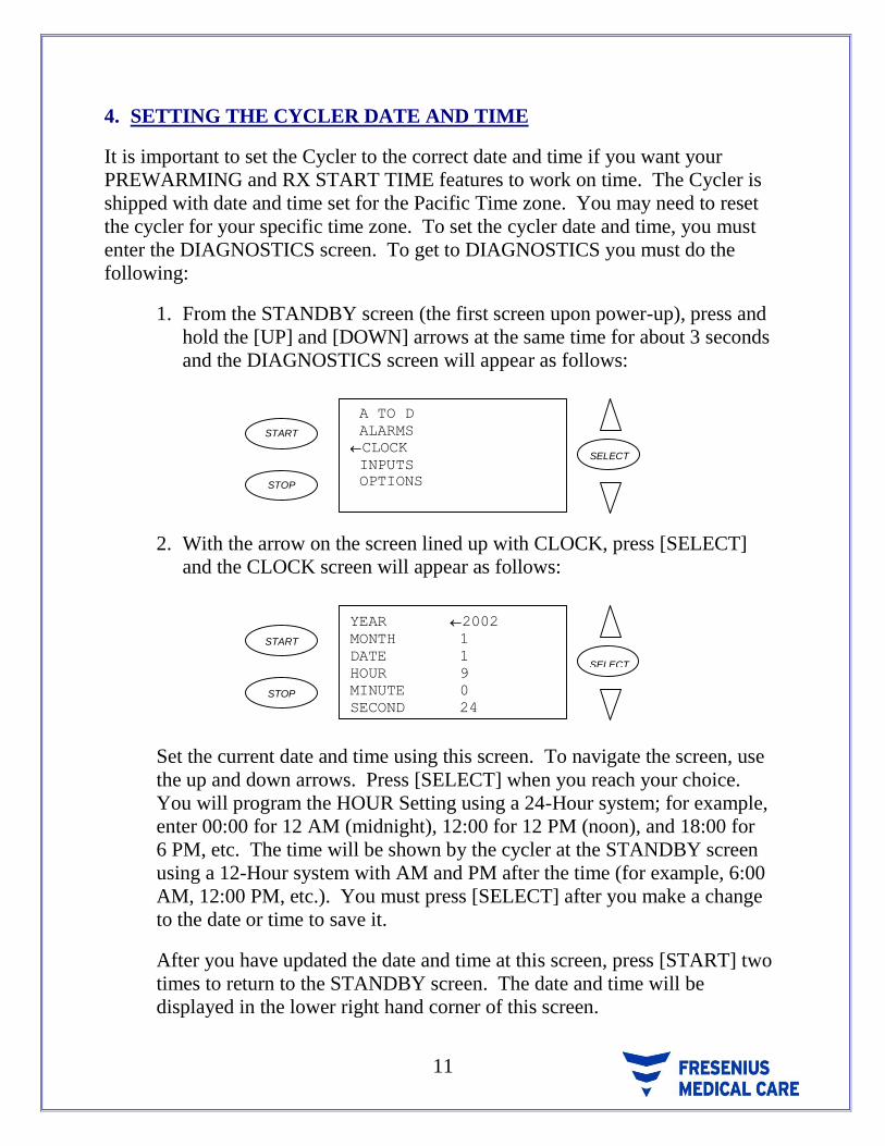
1. From the STANDBY screen (the first screen upon power-up), press and
hold the [UP] and [DOWN] arrows at the same time for about 3 seconds
and the DIAGNOSTICS screen will appear as follows:
START
STOP
A TO D
ALARMS
CLOCK
INPUTS
OPTIONS
SELECT
2. With the arrow on the screen lined up with CLOCK, press [SELECT]
and the CLOCK screen will appear as follows:
START
STOP
YEAR 2002
MONTH 1
DATE 1
HOUR 9
MINUTE 0
SECOND 24
SELECT
Set the current date and time using this screen. To navigate the screen, use
the up and down arrows. Press [SELECT] when you reach your choice.
You will program the HOUR Setting using a 24-Hour system; for example,
enter 00:00 for 12 AM (midnight), 12:00 for 12 PM (noon), and 18:00 for
6 PM, etc. The time will be shown by the cycler at the STANDBY screen
using a 12-Hour system with AM and PM after the time (for example, 6:00
AM, 12:00 PM, etc.). You must press [SELECT] after you make a change
to the date or time to save it.
After you have updated the date and time at this screen, press [START] two
times to return to the STANDBY screen. The date and time will be
displayed in the lower right hand corner of this screen.

12 P/N 470203 Rev. H
5. TREATMENT SETTINGS AND OPTIONS
General treatment Settings and Options are programmed into the Newton IQ
Cycler at the manufacturer. You must reprogram the Cycler Settings and Options
for your personal prescription before you start your first treatment. Do the
following to access the Settings and Options:
NOTE: You may skip this section and refer to the “USING THE
PRESCRIPTION UPLOAD FEATURE” of these Operator Instructions if
you are told by your physician or dialysis nurse to use the Upload feature.
1. Turn on the Cycler using the POWER switch located on the back panel
of the Cycler. After the Cycler performs its power-up self-test, it will
display the STANDBY screen as follows:
START
STOP
01/01/02
9:00 AM
SELECT
2. Press [START]. Instructions for programming or starting the treatment
will appear.
START
STOP
PRESS SELECT TO
PROGRAM SETTINGS.
PRESS START TO
BEGIN TREATMENT. SELECT
3. Press [SELECT] to enter the SETTINGS/OPTIONS screen as follows:
SELECT
START
STOP
DATA SHEETS
PATIENT DATA
PT WEIGHT 125 LBS
# FILLS 5
# PAUSES 1
PAUSE VOLUME 3000

13
TREATMENT SETTINGS AND OPTIONS (cont’d)
Additional Settings and Options that are not displayed on the initial screen are
available by pressing the [DOWN] arrow.
Descriptions of the various Settings and Options follow.
a. Patient Weight (PT WEIGHT)
(Range is 0, and 20 – 500 lbs. or 0 and 9 – 227 kgs.)
You may enter your initial weight here, in either pounds (lbs.) or kilograms
(kgs.). Refer to the “ADDITIONAL OPTIONS” section of this manual to
learn how to set the Cycler for recording your weight in either pounds or
kilograms
The Patient Weight value will automatically be updated after each treatment
if your physician or dialysis nurse has you use the Patient Data Entry feature
of the Cycler. Refer to the “PATIENT DATA ENTRY” section of these
instructions to learn how to use the Patient Data Entry feature of the Cycler.
b. Number of Fills (# FILLS)
(Range is 1 – 20 Fills)
The # FILLS is the number of times the peritoneum is filled will dialysate
fluid. The # FILLS includes any programmed Pause volumes, CCPD
volumes, and Last Fill volume. A Last Fill volume of zero is not counted in
the number of Fills because no fill volume is delivered to the peritoneum.
NOTE: This number is prescribed by your physician.
c. Number of Pauses (# PAUSES)
(Range is 0 – 5 Pauses)
The # PAUSES indicates the number of PAUSES you are supposed to do
during the treatment. A PAUSE is a special type of Dwell that allows you to
Dwell while either connected or disconnected from the Cycler. It also
differs from other Dwells because it is not a timed function; that is, you can
PAUSE for as short or long as you would like.

14 P/N 470203 Rev. H
TREATMENT SETTINGS AND OPTIONS (cont’d)
Before each PAUSE, the Cycler will Drain and then Fill you. After the Fill,
the Newton IQ Cycler automatically goes into a PAUSE. The Cycler will
remain in the PAUSE phase indefinitely until you continue the treatment by
pressing [START].
With PD Plus Therapy, you can program up to five PAUSES. The “USING
MULTIPLE PAUSES” section of these Operator Instructions describes how
to operate the Cycler when there is more than one PAUSE programmed.
You can only program one PAUSE when using Tidal Therapy.
NOTE: The number of pauses is prescribed by your physician.
d. Pause Volume (PAUSE VOL)
(Range is: 500 – 4,000 ML)
WARNING! It is possible to program the Cycler to fill with more than
3,000 ml. Do not fill with more unless you are told to do so
by your physician or dialysis nurse.
The PAUSE VOL is the amount of solution that will be delivered during the
Pause exchange(s). This amount cannot be more than 150% (1 ½) of the
CCPD Volume.
You can not program a PAUSE VOL when # PAUSES is set to zero (0).
If you are doing PD Plus Therapy, you will probably program PAUSE VOL,
CCPD VOL, and LAST FILL Volume.
If you are doing exchanges only while you are sleeping and then are
receiving a Fill before you disconnect, you will not program a Pause
exchange. In this case, you will program a CCPD VOL and a LAST FILL
Volume.
NOTE: CCPD volumes and last fills are prescribed by your physician.

15
TREATMENT SETTINGS AND OPTIONS (cont’d)
e. CCPD Volume (CCPDVOL)
(Range is: 500 – 4,000 ML)
WARNING! It is possible to program the Cycler to fill with more than
3,000 ml. Do not fill with more unless you are told to do so
by your physician or dialysis nurse.
The CCPD VOL is the amount of solution that is delivered during the
exchanges occurring while you are typically sleeping.
NOTE: The amount of solution is prescribed by your physician.
f. Last Fill Volume (LAST FILL)
(Range is: 0 or 50 – 4,000 ML)
WARNING! It is possible to program the Cycler to fill with more than
3,000 ml. Do not fill with more unless you are told to do so
by your physician or dialysis nurse.
The LAST FILL is the amount of solution left in your peritoneum before
disconnecting from the machine, at the completion of the treatment. The
LAST FILL amount can not be programmed for more than 150% (1 ½) of
the CCPD Volume.
If you plan to be empty during the day, you will program the LAST FILL to
0 ML.
NOTE: The last fill volume is prescribed by your physician.
NOTE: If the delivered volume of the last fill is greater than 90% of the
prescribed volume and within 200 ml of the prescribed volume, an
alarm will not sound during the last fill.
The cycler will display the delivered amount on the COMPLETE
screen. However, if you consistently get a message that your fill is
less than prescribed, notify your clinic.

16 P/N 470203 Rev. H
TREATMENT SETTINGS AND OPTIONS (cont’d)
g. Total Volume (TOTAL VOL)
The TOTAL VOL tells you the amount of Solution needed for your
treatment. The Cycler automatically calculates the TOTAL VOL for you
based on the number of Fills and the Volumes you programmed
(PAUSE VOL, CCPD VOL, and LAST FILL).
To get the correct TOTAL VOL displayed on the screen; you must program
your Dialysis Fill Volumes starting with the CCPD VOL, then the
PAUSE VOL, and finally the LAST FILL.
NOTE: This amount is prescribed by your physician.
h. Fill Time (FILL TIME)
(Range is 1 – 59 Minutes)
The FILL TIME is the amount of time needed to fill your peritoneum with
Dialysis Solution. You may fill more quickly lying down than sitting or
standing up because there is less pressure in your abdomen when you are
lying down.
i. Dwell Time (DWELL TIME)
(Range is 5 Minutes – 9 Hours 55 Minutes)
The DWELL TIME is the time allowed for the actual dialysis to take place
during each exchange. The time needed is usually decided by your
physician.
j. Drain Time (DRAIN TIME)
(Range is 1 – 59 Minutes)
The DRAIN TIME is the time needed to completely drain your peritoneum.
You may drain faster sitting or standing up than lying down because there is
more pressure in your abdomen when you are sitting or standing up. Your
position relative to the drain bags will also affect how well you drain.
17
TREATMENT SETTINGS AND OPTIONS (cont’d)
k. Sleep Time (SLEEP TIME)
The SLEEP TIME tells you the estimated amount of time, usually spent
sleeping, that you’ll need to complete the cycling exchanges.
The Cycler automatically calculates the SLEEP TIME for you based on the
FILL, DWELL, and DRAIN times you program. Any treatment time prior
to the last programmed PAUSE is not included in the SLEEP TIME
calculation.
The SLEEP TIME is a “count-down” clock. As your treatment progresses,
the SLEEP TIME value will decrease. At the completion of the treatment,
the SLEEP TIME displays “0” minutes when viewed from the COMPLETE
screen.
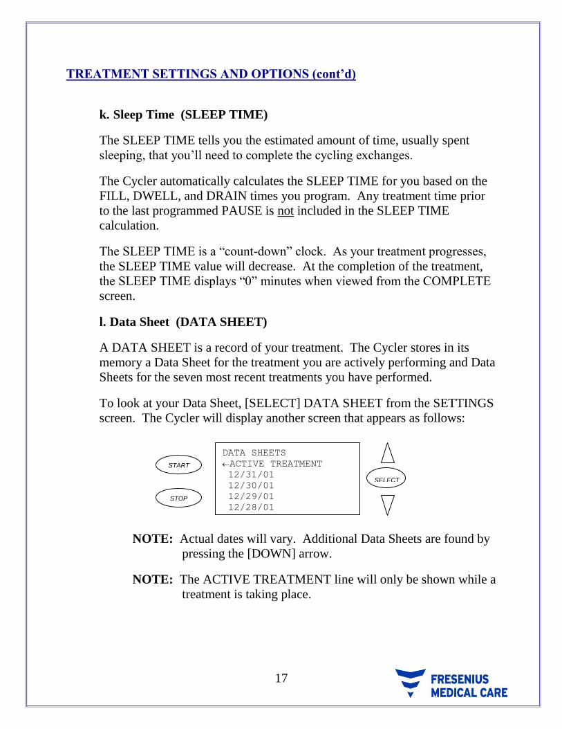
l. Data Sheet (DATA SHEET)
A DATA SHEET is a record of your treatment. The Cycler stores in its
memory a Data Sheet for the treatment you are actively performing and Data
Sheets for the seven most recent treatments you have performed.
To look at your Data Sheet, [SELECT] DATA SHEET from the SETTINGS
screen. The Cycler will display another screen that appears as follows:
START
STOP
DATA SHEETS
ACTIVE TREATMENT
12/31/01
12/30/01
12/29/01
12/28/01
SELECT
NOTE: Actual dates will vary. Additional Data Sheets are found by
pressing the [DOWN] arrow.
NOTE: The ACTIVE TREATMENT line will only be shown while a
treatment is taking place.

18 P/N 470203 Rev. H
TREATMENT SETTINGS AND OPTIONS (cont’d)
Press the [DOWN] arrow to line up the Cycler cursor with the Data Sheet
you want to view and press [SELECT]. The Cycler will advance to the Data
Sheet. The Data Sheet from your treatment will show your actual fill and
drain volumes for each cycle of your treatment. A sample Data Sheet
appears as follows.
START
STOP
CYC FILL DRAIN UF
0 1730 230
1 2000 2180 410
2 2000 2300 710
3 2000 2200 910
4 2000 2100 1010
SELECT
NOTE: The displayed volumes will vary to reflect the actual
volumes that occur during your treatments.
How to read a Data Sheet is found in the “LOOKING AT YOUR
TREATMENT RECORD” section of these Operator Instructions.
m. Patient Data (PATIENT DATA)
PATIENT DATA may be a part of the record of your treatment. You will
see this screen unless your clinic has “turned off” this option when your
IQcard was programmed. At this screen, you are prompted to enter your
blood pressure, weight, and solution used during your treatment. Refer to
the “PATIENT DATA ENTRY FEATURE” section of these Operator
Instructions for instructions on how to enter information into this screen.
n. Fast Fill/Drain (FAST FILL/DRAIN)
(Values are “YES” or “NO”, Default is “YES”)
When FAST FILL/DRAIN is set to “YES”, the Cycler automatically goes
into the next phase of the treatment when the Fill or Drain takes less time
than programmed. The unused FILL TIME and DRAIN TIME will be
added to your next Dwell.
19
TREATMENT SETTINGS AND OPTIONS (cont’d)
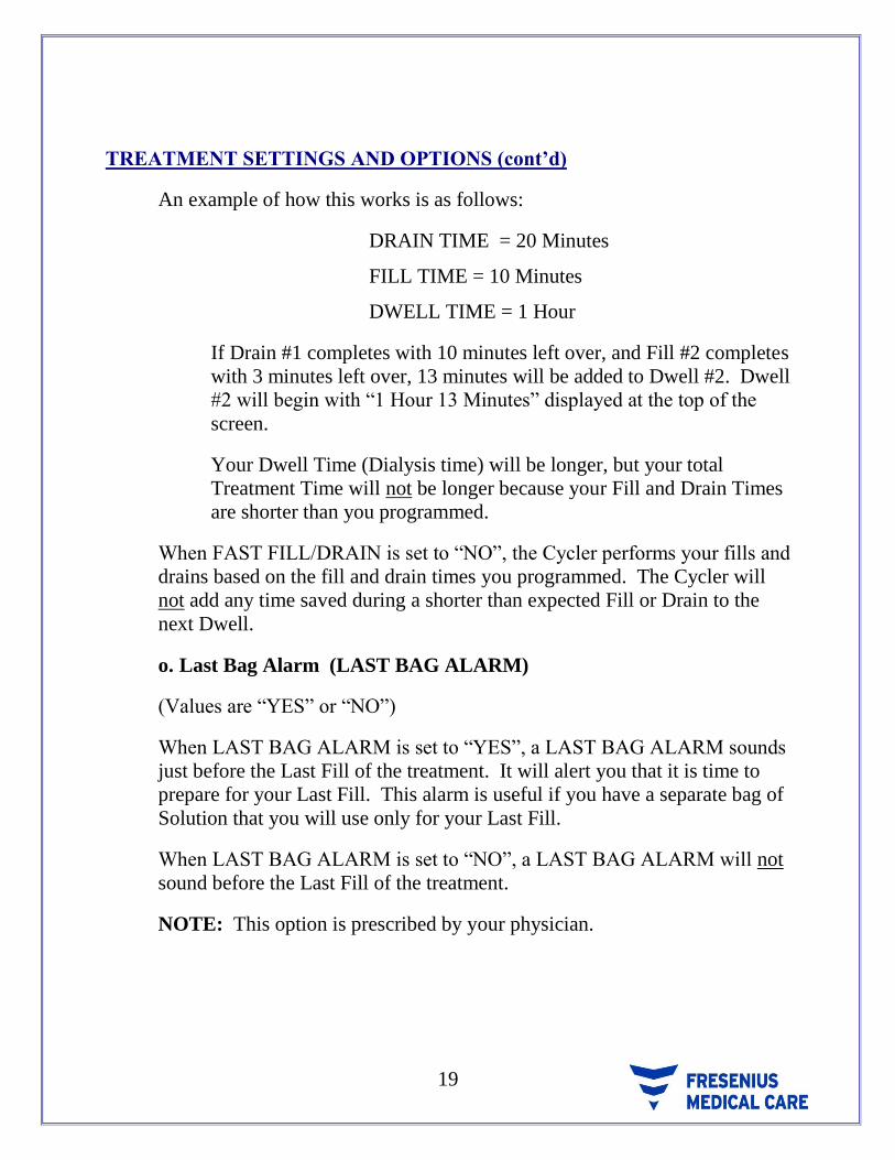
An example of how this works is as follows:
DRAIN TIME = 20 Minutes
FILL TIME = 10 Minutes
DWELL TIME = 1 Hour
If Drain #1 completes with 10 minutes left over, and Fill #2 completes
with 3 minutes left over, 13 minutes will be added to Dwell #2. Dwell
#2 will begin with “1 Hour 13 Minutes” displayed at the top of the
screen.
Your Dwell Time (Dialysis time) will be longer, but your total
Treatment Time will not be longer because your Fill and Drain Times
are shorter than you programmed.
When FAST FILL/DRAIN is set to “NO”, the Cycler performs your fills and
drains based on the fill and drain times you programmed. The Cycler will
not add any time saved during a shorter than expected Fill or Drain to the
next Dwell.
o. Last Bag Alarm (LAST BAG ALARM)
(Values are “YES” or “NO”)
When LAST BAG ALARM is set to “YES”, a LAST BAG ALARM sounds
just before the Last Fill of the treatment. It will alert you that it is time to
prepare for your Last Fill. This alarm is useful if you have a separate bag of
Solution that you will use only for your Last Fill.
When LAST BAG ALARM is set to “NO”, a LAST BAG ALARM will not
sound before the Last Fill of the treatment.
NOTE: This option is prescribed by your physician.

20 P/N 470203 Rev. H
TREATMENT SETTINGS AND OPTIONS (cont’d)
p. Prewarm Bags (PREWARM BAGS)
(Values are “YES” or “NO”)
When PREWARM BAGS is set to “YES”, the Heater turns on to warm your
Dialysis Solution before your first exchange. The Heater will remain on
until the Solution Bags have reached a comfortable temperature. It takes
about 3 hours for the Solution Bags to reach a comfortable temperature.
Once the bags are warm, the Heater will turn off and on to maintain a
comfortable temperature. The Heater will turn off (and remain off) at the
end of the treatment after you have returned the Cycler to the STANDBY
screen.
In order for the Heater to automatically come on for the next treatment, the
Cycler must:
have the POWER switch “ON”
have the HEATER switch “ON” and
be at the STANDBY screen
When PREWARM BAGS is set to “NO”, the Heater is on at all times, even
between treatments. The Cycler Power switch or the Heater switch must be
turned “OFF” to turn off the Heater.
q. RX Start Time (RX START TIME)
The RX START TIME is the time of day you usually start your first
exchange using the Cycler. For example, if you are doing a PAUSE, you
might set the RX START TIME for 6 PM. If you are doing your first
exchange at bedtime, you might set the RX START TIME for 10 PM.
NOTE: The RX START TIME is only used to begin the pre-warming of
the solution bags.
If PRE WARM BAGS is set to “NO”, RX START TIME will display “N/A”
and can not be changed.

21
TREATMENT SETTINGS AND OPTIONS (cont’d)
r. Tidal Settings (TIDAL SETTINGS)
(Values are “YES” or “NO”)
WARNING! It is possible to program the Cycler to fill with more than
3,000 ml. Do not fill with more than instructed by your
physician.
Most of the programming for Tidal Therapy is done through TIDAL
SETTINGS.
By selecting TIDAL SETTINGS from the SETTINGS screen, you will enter
another screen that appears as follows:
SELECT
START
STOP
TIDAL THERAPY NO
FIRST FILL N/A
TIDAL FILL N/A
TIDAL DRAIN N/A
To program TIDAL THERAPY, press [SELECT], then press the [UP] or
[DOWN] arrow keys to change the setting to “YES”. Press [SELECT] again
to lock-in TIDAL THERAPY.
After you set TIDAL THERAPY to “YES”, you will then need to program
the FIRST FILL. Next, set the TIDAL FILL and TIDAL DRAIN. To set all
other Tidal Therapy Settings press [START] to go back to the SETTINGS
screen.
When you set TIDAL THERAPY to “NO”, FIRST FILL, TIDAL FILL and
TIDAL DRAIN will all display “N/A” since they are only needed for
TIDAL THERAPY.
Press [START] once to exit the TIDAL SETTINGS screen and return to the
SETTINGS screen. Press [START] once more to exit the SETTINGS
screen and to return to the STANDBY screen.
NOTE: Therapy type is prescribed by your physician.

22 P/N 470203 Rev. H
6. ADDITIONAL OPTIONS
Several additional Cycler Options that you can program are as follows:
Screen Blanking
Speaker Volume
Speaker Pitch
Language
Allow > 3L?
Weight Units
IQcard Used?
Add Diurnal UF?
These Options are found in the DIAGNOSTICS screen, not from the SETTINGS
screen. To get to DIAGNOSTICS and OPTIONS you must do the following:
1. From the STANDBY screen, press and hold the [UP] and [DOWN]
arrows at the same time for about 3 seconds and the DIAGNOSTICS
screen will appear as follows:
START
STOP
A TO D
ALARMS
CLOCK
INPUTS
OPTIONS
SELECT
2. Press the [DOWN] arrow to move the cursor to OPTIONS.
3. Press [SELECT] and the OPTIONS screen will appear as follows:
START
STOP
SCREEN BLANKING OFF
SPEAKER VOLUME 6
SPEAKER PITCH 0
LANGUAGE ENGLISH
ALLOW>3 LITERS? NO
WEIGHT UNITS LBS
IQCARD USED? YES
SELECT

23
ADDITIONAL OPTIONS (cont’d)
a. Screen Blanking (SCREEN BLANKING)
(Values are “YES” or “NO”) (The Values Default is “NO”)
When SCREEN BLANKING is set to “YES”, the Cycler screen will go
blank after 5 minutes if no button is pressed, or if no alarm sounds. If any
button is pressed, or if there has been a Cycler alarm, the screen will
reappear. If, after another 5 minutes, no buttons are pressed or no alarms
sound, the screen will go blank again.
The cycler will continue the treatment even when the screen is blank. Use
SCREEN BLANKING if you like to sleep without any lighting in your
room.
When SCREEN BLANKING is set to “NO”, the cycler screen stays on
whenever the cycler is on.
b. Alarm Volume (ALARM VOLUME)
(Values are from “1” through “10”) (The Values Default is “6”)
The cycler is shipped with the Alarm Volume set to “6”. You can adjust the
volume between “1” (quiet) and “10” (loud), depending on the alarm volume
you prefer.
c. Alarm Pitch (ALARM PITCH)
(Values are from “0” through “52”) (The Values Default is “0”)
The Cycler is shipped with the Alarm Pitch set to “0”. You can adjust the
pitch between “0” and “52” depending on the alarm pitch you prefer.
d. Language (LANGUAGE)
(LANGUAGE “ENGLISH” or “FRENCH” or “SPANISH”)
The Cycler is shipped with all screens set to English. Use LANGUAGE to
see the screens in French or Spanish.

24 P/N 470203 Rev. H
ADDITIONAL OPTIONS (cont’d)
e. Allow > 3 Liters? (ALLOW>3 LITERS?)
(Values are “YES” or “NO”)
The largest fill volume is 4 liters. If your physician wants you to use more
than 3 liters, you must set this option.
NOTE: If your IQcard has been programmed for more than 3 liters you
must change the ALLOW > 3 LITERS to “YES” before inserting
the IQcard. If you do not do this, you will get a TX SETTING
CORRUPTED alarm when you place the IQcard into the Cycler.
f. Weight Units (WEIGHT UNITS)
(Values are “LBS” or “KGS”) (The Values Default is “LBS”)
Use the weights you have been taught by your dialysis facility, either LBS
for pounds or KGS for kilograms.
g. IQcard Used? (IQCARD USED?)
(Values are “YES” or “NO”) (The Values Default is “YES”)
When IQCARD USED? is set to “YES”, the cycler is aware that you plan to
use an IQcard to record your treatment data. An IQcard must be inserted
into the slot on the front of the cycler. All HELP screens and alarms for the
IQcard are active when you set IQCARD USED? to “YES”.
When IQCARD USED is set to “NO”, the cycler is aware that you do not plan
to use an IQcard to record your treatment data. All HELP screens and alarms
for the IQcard are not active when you set IQCARD USED? to “NO”.
h. Add Diurnal UF? (ADD DIURNAL UF?)
(The Diurnal UF Default is “YES”) When Add Diurnal UF? is set to “YES” the Drain 0 UF Volume will be added
to the total UF volume calculated for that treatment.
When Add Diurnal UF? is set to “NO” the Drain 0 UF Volume will not be
added to the total UF volume calculated for that treatment.

25
7. USING THE PRESCRIPTION UPLOAD FEATURE
When your clinic changes your prescription using the IQcard Software Program,
the next time you put your IQcard into the cycler, your new prescription will
automatically upload into your cycler.
The upload screen will come up with the new settings. You must view and either
accept or reject the settings. You must scroll down through three screens to the
last line, which reads USE NEW SETTINGS?. To accept the prescription change,
press [SELECT] and “YES” will appear next to USE NEW SETTINGS?
START
STOP
JONES,ROBERT
TIDAL THERAPY NO
# FILLS 6
# PAUSES 1
PAUSE VOL 2500ML
CCPD VOL 3000ML
SELECT
START
STOP
LAST FILL 2500ML
FILL TIME 20 MIN
DWELL TIME 1HR 30MIN
DRAIN TIME 30 MIN
FAST FILL/DRAIN YES
LAST BAG ALARM NO
SELECT
START
STOP
DRAIN TIME 30 MIN
FAST FILL/DRAIN YES
LAST BAG ALARM NO
PRE WARM BAGS YES
RX START TIME 10:00PM
USE NEW SETTINGS?YES
SELECT
Press [START] to accept the upload and to return to the STANDBY screen. Your
Cycler settings have been changed to the new prescription.
WARNING! Check the new prescription carefully. If your name is not shown or
the new prescription is not right, change USE NEW SETTINGS? to
“NO” and press [START]. If you do not accept the new settings,
the upload screen will be shown every time you remove and reinsert
your IQcard from the cycler.

26 P/N 470203 Rev. H
8. YOUR PERSONAL PRESCRIPTION
Have your clinic fill this sheet out for you and use it to check the prescription or to
program your Cycler.
NAME: ___________________________________
TREATMENT SETTINGS AND OPTIONS:
# FILLS __________
# PAUSES __________
PAUSE VOL __________
CCPD VOL __________
LAST FILL __________
FILL TIME __________
DWELL TIME __________
DRAIN TIME __________
FAST FILL/DRAIN YES or NO
LAST BAG ALARM YES or NO
PREWARM BAGS YES or NO
RX START TIME __________ AM or PM
TIDAL SETTINGS
TIDAL THERAPY YES or NO
FIRST FILL __________
TIDAL FILL __________
TIDAL DRAIN __________
OTHER OPTIONS:
SCREEN BLANKING YES or NO
LANGUAGE : ENGLISH FRENCH SPANISH
ALLOW >3 LITERS YES or NO
WEIGHT UNITS LBS or KGS
ADD DIURNAL UF? YES or NO
Checked by: _________________________ Date: __________

27
Heater Switch
Power
Switch
9. GETTING READY FOR YOUR TREATMENT
a. Prepare cycler for use
IF YOU ARE USING AN IQCARD BE SURE IT IS INSERTED BEFORE
YOU TURN ON THE CYCLER.
Turn “ON” the cycler with the POWER switch on the back of the cycler.
Do not have anything on the cycler scale (except for the Bag Organizer and
Drain Hook) when turning on the Cycler.
The Cycler POWER and HEATER switches should be left “ON” after the
first treatment for the Heater to automatically come on to warm your
Solution Bags. Once the Cycler is left “ON”, you can leave bags on the
Cycler Scale.
WARNING! Do not use external heating sources not authorized by
Fresenius Medical Care to warm your solution bags. Contact your clinic for
more information.

28 P/N 470203 Rev. H
GETTING READY FOR YOUR TREATMENT (cont’d)
When you turn on the cycler, it will do a complete self-test of its electronics,
heater, and scale. The Front Panel screen will display the cycler software version
as well as a testing message as follows:
START
STOP
S/W VER. 1.XXN
NEWTON IQ
TESTING…
SELECT
At the end of a successful power-up self-test, the cycler will display the
STANDBY screen as follows:
SELECT
STOP
START
01/01/02
10:00PM
b. Tubing Set-Up
At this point, you can begin the cycler treatment setup.
Start the cycler treatment setup with clean hands. Gather your supplies.
1. Press [START]. Instructions for programming or starting the treatment
will appear.
SELECT
STOP
START
PRESS SELECT TO
PROGRAM SETTINGS.
PRESS START TO
BEGIN TREATMENT.

29
GETTING READY FOR YOUR TREATMENT (cont’d)
2. Press [START] again and follow the instructions on the screen.
STOP
START
OPEN YELLOW CLAMPS.
PUT BAGS ON SCALE.
LOAD TUBING.
CLOSE RED CLAMPS.
PRESS START TO
CONTINUE.
SELECT
3. If your bags are not already on the heater, choose the bag(s) of Dialysis
Solution for your treatment. Take off the outer cover of the bags, and
put the bags in the Bag Organizer that sits on top of the cycler. The
solution bags should be positioned with their outlet ports in the U-shaped
cutouts in the Bag Organizer.
Five Important Dialysate bag checks
Dialysate Strength
Dialysate Volume
Expiration Date
Clear Fluid
No Leaks
WARNING! When the bags are in the Bag Organizer, check the Heater
Tray and Bag Organizer to be sure they are free of
obstructions and do not touch the top of the cycler cabinet
or the Stand Pole. Also check that the Manifold holder is
not touching the Bag Organizer. Interference with the
Heater Tray may result in inaccurate weighing of Dialysis
Solution, and possibly result in patient injury.
4. Open the Newton IQ Set tubing and lay it on top of the solution bags.
Close both red clamps. Only Newton IQ tubing sets can be used on the
Newton IQ Cycler.

30 P/N 470203 Rev. H
GETTING READY FOR YOUR TREATMENT (cont’d)
5. Put the Patient Line in the tubing holder provided on the side of the
cycler. The end of the Patient Line should be placed above the cycler’s
heater tray.
6. Place Tubing Manifold into the Manifold Holder. The single tubing line
will face up with the 4 lines facing down.
NOTE: Make sure there are no kinks in the tubing between the
Manifold and the valve assembly.
7. Open the Pump-to-Drain valve cover. Align the white tubing cassette
directly over the markers on the valves and press the cassette into place.
8. Close the Valve Cover.
NOTE: If the Valve Cover will not close completely, check to see if the
white tubing cassette is placed into the valve assembly
correctly. The cassette will only fit properly into the valve
assembly in one direction.
9. Open the Pump Cover.
10. Form a “V” shape with the pump segment tubing.
11. Press the bottom of the “V” into the middle of the pump opening
12. Pull the sides of the pump segment tubing down, so that they rest in the
pump notches, and are centered in the pump.
13. Make sure the side of the tubing with the yellow clamp matches the side
of the pump with the yellow strip.
14. Make sure that the direction of flow from drain bag to drain outlet
matches the diagram on the pump.
31
GETTING READY FOR YOUR TREATMENT (cont’d)
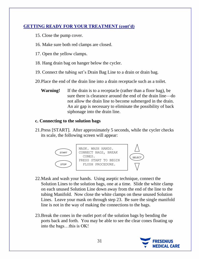
15. Close the pump cover.
16. Make sure both red clamps are closed.
17. Open the yellow clamps.
18. Hang drain bag on hanger below the cycler.
19. Connect the tubing set’s Drain Bag Line to a drain or drain bag.
20. Place the end of the drain line into a drain receptacle such as a toilet.
Warning! If the drain is to a receptacle (rather than a floor bag), be
sure there is clearance around the end of the drain line—do
not allow the drain line to become submerged in the drain.
An air gap is necessary to eliminate the possibility of back
siphonage into the drain line.
c. Connecting to the solution bags
21. Press [START]. After approximately 5 seconds, while the cycler checks
its scale, the following screen will appear:
SELECT
STOP
START
MASK. WASH HANDS.
CONNECT BAGS, BREAK
CONES.
PRESS START TO BEGIN
FLUSH PROCEDURE.
22. Mask and wash your hands. Using aseptic technique, connect the
Solution Lines to the solution bags, one at a time. Slide the white clamp
on each unused Solution Line down away from the end of the line to the
tubing Manifold. Now close the white clamps on these unused Solution
Lines. Leave your mask on through step 23. Be sure the single manifold
line is not in the way of making the connections to the bags.
23. Break the cones in the outlet port of the solution bags by bending the
ports back and forth. You may be able to see the clear cones floating up
into the bags…this is OK!

32 P/N 470203 Rev. H
GETTING READY FOR YOUR TREATMENT (cont’d)
Checklist Before Continuing:
Tubing Manifold inserted into the Manifold Holder.
Both red clamps are closed.
Patient Line is in tube holder on the side of the Cycler.
Patient Line is above the heater tray.
Solution Lines are connected to the solution bags
White clamps on unused Solution Lines are closed.
White clamps on used Solution Lines are open.
Cones in solution bags are fully broken.
White tubing cassette is placed over the valves and the valve cover is
completely closed.
Pump segment is loaded into the pump in the correct direction.
Both yellow clamps are open.
End of pump segment is connected to the Drain Line.
d. Tubing Flush and Prime
24. Press [START]. The cycler will flush the tubing set and perform tests to
make sure that the Newton IQ Set is installed and working correctly.
While this happens, the cycler will display the following screen:
START
STOP
PERFORMING
FLUSH PROCEDURE
PLEASE WAIT
SELECT

33
GETTING READY FOR YOUR TREATMENT (cont’d)
25. After the flush procedure is successfully completed., the following screen
will appear:
START
STOP
FLUSH COMPLETE
PRESS STOP TO REFLUSH
–OR–
LOWER MANIFOLD, OPEN
RED CLAMPS.
PRESS START TO PRIME.
SELECT
26. If you would like to repeat the flush procedure, press [STOP]. If you do
not need to repeat the tubing flush, open both red clamps and press
[START]. The Cycler will now prime the Patient Line. When you press
[START] to prime the Patient Line, the following screen will appear:
START
STOP
WHEN PATIENT LINE
PRIMED, CLOSE BLUE
CLAMP.
PRESS START.TO
CONTINUE.
SELECT
27. Hold the end of the Patient Line up above the Solution Bags on the top of
the Cycler. The Solution will travel up the Patient Line to the end of the
tubing as the Patient Line is gently lowered. This will remove air from
the Patient Line and is referred to as “priming the line”.
28. Close the blue clamp on the Patient Line when the Patient Line is
completely primed and then press [START].
NOTE: If you have programmed LAST BAG ALARM to “YES” and
are using a separate bag of Solution for your LAST FILL, you
must close the white clamp on this separate bag now.

34 P/N 470203 Rev. H
GETTING READY FOR YOUR TREATMENT (cont’d)
The next setup screen will appear as follows:
START
STOP
PRESS STOP TO REPRIME
-OR–
CONNECT PATIENT.
OPEN BLUE CLAMP.
OPEN CATHETER CLAMP.
THEN PRESS START.
SELECT
29. If you would like to repeat the Patient Line prime, press [STOP]. If you
do not need to repeat the Patient Line prime, you may connect to the
cycler at this point.
e. Connecting to the Cycler – Leave your mask on.
30. Clamp the catheter or transfer set.
31. Remove the protective cap from the end of the cycler tubing.
32. Depending on the catheter connection system you are using follow either
the stay•safe or Safe-Lock connection procedure for connecting to the
cycler set.
33. Open the blue clamp on the cycler’s Patient Line. Open the clamp on
your Catheter or Extension Line.
34. Press [START] to begin treatment
35. Check out flow for clarity and/or fibrin.

35
GETTING READY FOR YOUR TREATMENT (cont’d)
NOTE: Your treatment will always begin in Drain 0, which appears as
follows:
START
STOP
TIME LEFT: 20 MINUTES
DRAIN 0
DRAIN VOLUME 0 ML
SELECT

36 P/N 470203 Rev. H
10. THE TREATMENT
a. Treatment Phases (All Therapy Types)
Your treatment will always start in DRAIN 0 and then go to FILL 1. After
FILL 1, the treatment will go into PAUSE or DWELL (depending on your
program). How many times your treatment Pauses depends upon how many
Pauses you have programmed. If you have not programmed any Pauses the
exchange order is always the same, starting with a Drain, then a Fill, and
lastly, a Dwell.
As needed during the treatment, the cycler will test its drain system. While
this brief process happens, the cycler will display a message at the bottom of
the current screen stating that the Drain Bag is being tested.
In addition, as needed during the treatment, the cycler will pump the fluid
from the Drain Bag to your waste site. While this process happens the
cycler will display a message at the bottom of the current screen stating that
the Drain Bag is being emptied. The cycler may leave a small amount of
fluid in the Drain Bag after completing the emptying process – this is
normal. At the end of the treatment, the cycler will leave approximately 500
ml of fluid in the drain bag – this also is normal.
The treatment will end with a Fill if a LAST FILL volume has been
programmed. If you have set the Last Fill volume to 0 (zero), your
treatment will end in a Drain.
37
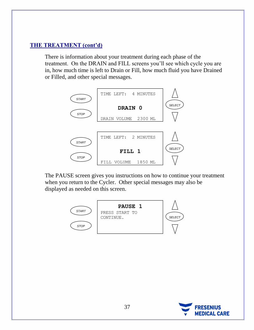
THE TREATMENT (cont’d)
There is information about your treatment during each phase of the
treatment. On the DRAIN and FILL screens you’ll see which cycle you are
in, how much time is left to Drain or Fill, how much fluid you have Drained
or Filled, and other special messages.
SELECT
STOP
START
TIME LEFT: 4 MINUTES
DRAIN
DRAIN 0
VOLUME 2300 ML
SELECT
STOP
START
TIME LEFT: 2 MINUTES
FILL VOLUME
FILL 1
1850 ML
The PAUSE screen gives you instructions on how to continue your treatment
when you return to the Cycler. Other special messages may also be
displayed as needed on this screen.
SELECT
STOP
START
PAUSE 1PRESS START TO
CONTINUE.

38 P/N 470203 Rev. H
THE TREATMENT (cont’d)
The DWELL screen tells you how much time is left to Dwell. This includes
the extra time that is added to the Dwell if you have set FAST FILL/DRAIN
to “YES”. Other special messages may also be displayed as needed on this
screen.
SELECT
STOP
START
DWELL 2
TIME LEFT: 1HR 30MIN
b. Using One PAUSE
Your physician will decide if you will be doing a Pause. If you are doing
one Pause exchange, the cycler will automatically enter the PAUSE screen
after FILL 1. The PAUSE screen will appear as follows:
SELECT
STOP
START
PAUSE 1PRESS START TO
CONTINUE.
While the cycler is at the PAUSE screen, you can disconnect from the
cycler.
To disconnect from the cycler after a pause exchange follow the disconnect
procedure for your type of catheter connection either stay•safe or Safe-Lock

39
THE TREATMENT (cont’d)
The cycler will remain at the PAUSE screen until you press [START]. You
don’t need to press [START] until you are ready to reconnect to the cycler
and continue your treatment.
When you are ready to continue the treatment, you follow the same steps
that you did for connection earlier in the treatment.
Press [START], and a HELP screen will appear as follows:
START
STOP
MASK. WASH HANDS.
CONNECT PATIENT.
OPEN ALL CLAMPS.
THEN PRESS START. SELECT
CONNECTING TO THE CYCLER AFTER A PAUSE EXCHANGE:
1. Clamp your catheter unless you have a transfer set that is already
clamped.
2. Check to make sure the blue clamp on the patient end of the tubing
set is closed.
3. Mask and wash your hands.
4. Remove the plastic shrink-wrap from the next patient connection
on the cycler tubing.
5. Depending on the catheter connection system you are using follow
either the stay•safe or Safe-Lock connection procedure for
connecting to the cycler set.
6. Open the blue clamp on the Patient Line. Open the clamp on your
Catheter or Extension Line. Press [START].
The treatment will begin again in DRAIN 1.

40 P/N 470203 Rev. H
THE TREATMENT (cont’d)
c. Using Multiple PAUSES
Your physician will decide if you will be doing multiple Pauses. To perform
multiple Pauses you will need to add a Multiple Tubing Segment (MTS) to
the Patient Line of your Newton IQ Set tubing. Use a Two-Segment MTS
for up to three programmed Pauses, and use a Four-Segment MTS for up to
five programmed Pauses. Follow the instructions that come with the MTS
set for its proper use.
WARNING! Do not reconnect to a Patient Line connector that has already
been used.
If you are doing multiple Pauses, the cycler will automatically enter the first
PAUSE screen after FILL 1. The PAUSE screen will appear as follows:
While the cycler is at the PAUSE screen, you can disconnect from the
cycler.
SELECT
STOP
START
PAUSE 1PRESS START TO
CONTINUE.
To disconnect from the cycler after a pause exchange (when using more than
one pause)
1. Close the roller clamp on your transfer set (if you have a transfer
set).
2. Close the blue clamp on the Patient Line.
3. To disconnect from the cycler follow the disconnect procedure for
your type of catheter connection either stay•safe or Safe-Lock.
4. Place the end of the cycler tubing set in the tubing holder on either
side of the cycler.
The cycler will remain at the PAUSE screen until you press [START]. You
don’t need to press [START] until you are ready to reconnect to the cycler
and continue your treatment.

41
THE TREATMENT (cont’d)
When you are ready to continue the treatment, you follow the same steps
that you followed for connection earlier in the treatment.
Press [START], and a HELP screen will appear as follows:
SELECT
STOP
START
MASK. WASH HANDS.
CONNECT PATIENT.
OPEN ALL CLAMPS.
THEN PRESS START.
d. Connecting to the Cycler after more than one Pause Exchange:
1. Clamp your catheter unless you have a transfer set that is already
clamped.
2. Check to make sure the blue clamp on the patient end of the tubing
set is closed.
3. Mask and wash your hands.
4. Remove the plastic shrink-wrap from the next patient connection
on the cycler tubing.
5. Depending on the catheter connection system you are using, follow
either the stay•safe or Safe-Lock connection procedure for
connecting to the cycler set.
6. Open the blue clamp on the Patient Line. Open the clamp on your
Catheter or Extension Line. Press [START].
The treatment will begin again in DRAIN 1. When DRAIN 1 completes, the
cycler will enter FILL 2. When FILL 2 completes, the cycler will enter the
second PAUSE screen. The steps for performing the second and subsequent
PAUSES are the same as described above for the first PAUSE.
At the completion of all your programmed PAUSES, the cycler will advance
to the CCPD, or Last Fill phase of your treatment depending on your
prescription.

42 P/N 470203 Rev. H
THE TREATMENT (cont’d)
e. Interrupting the Treatment
The treatment can be interrupted for 10 minutes at any time by pressing
[STOP]. You should use INTERRUPT during a treatment before moving
the cycler or anything on the cycler scale. The screen will display the
following:
The TIME LEFT shown on the INTERRUPT screen is the time remaining in
the current phase that the treatment was in before you interrupted the
treatment. To resume the treatment, press [START].
If you don’t resume the treatment within 10 minutes, the cycler will sound
an alarm alerting you the treatment has been INTERRUPTED TOO LONG.
An INTERRUPTED TOO LONG screen appears as follows:
START
STOP
INTERRUPT
TOO LONG
PRESS STOP TO MUTE.
SELECT
To clear this alarm, press [STOP] to mute the alarm, then [START] to
continue the treatment.
S E L E C T
S T O P
S T A R T : 5 8 M I N U T E S T I M E L E F T
I N T E R R U P T
S/W VER. 1.11N

43
THE TREATMENT (cont’d)
f. Bypassing
Bypassing (or skipping) any phase of your treatment should be avoided
unless you’ve discussed situations that may require bypassing with your
doctor or dialysis nurse. If you need to BYPASS, press [START] twice
quickly, and you will see a question asking you if you really want to bypass.
START
STOP
BYPASS? PRESS START TWICE
TO BYPASS.
SELECT
Press [START] twice again quickly to complete the BYPASS process. If
you accidentally started the BYPASS process by pressing [START] twice,
don’t do anything, and in a few seconds the cycler will automatically return
to where it was before you accidentally started the BYPASS.
g. Moving the cycler During Your Treatment
The Newton IQ cycler can be moved at any time during the treatment by
doing the following:
1. Press [STOP] to INTERRUPT the treatment. This “freezes” the
scale to allow moving the cycler without an alarm sounding.
2. Unplug the cycler if you are going any further than the length of
the cycler electrical cord.
NOTE: If you unplug the cycler, it will power off – this is
normal. When you plug the cycler back in, special
screens will guide you with resuming or ending the
treatment.

44 P/N 470203 Rev. H
THE TREATMENT (cont’d)
3. Stand behind the cycler. Grab the Hanger Rod located at the top of
the Cycler Stand and pull (don’t push) the cycler to its new
location. The Hanger Rod provides a convenient “handle” for
moving the cycler.
4. If you did not unplug the cycler, press [START] to continue the
treatment.
5. If you unplugged the cycler, plug in the cycler into a properly
grounded three-prong outlet. The cycler will power back on
automatically and display screens to guide you with resuming or
ending the treatment.
h. Completing the Treatment
At the end of your treatment, the cycler will automatically advance to the
COMPLETE screen. If there is fluid in the drain bag, the cycler will empty
all but 500 ml of the fluid in the drain bag, after the emptying is complete
the screen will appear as follows:
START
STOP
NET UF 1500 ML
COMPLETE
PRESS STOP FOR
STANDBY.
SELECT
You may disconnect from the cycler at this point. Refer to
“DISCONNECTING FROM THE CYCLER” section of these Operator
Instructions for the procedure for disconnecting.

45
11. DISCONNECTING FROM THE CYCLER
1. Close the blue clamp on the Cycler Patient Line.
2. Close the clamp on your Catheter or Transfer Set (if you have a Transfer
Set).
3. To disconnect from the cycler follow the disconnect procedure for your type
of catheter connection either stay•safe or Safe-Lock.
4. Place the end of the Cycler tubing set in the tubing holder on either side of
the Cycler.

46 P/N 470203 Rev. H
12. PATIENT DATA ENTRY FEATURE
Unless your clinic has turned off this feature, you can put your weight, blood
pressure (B/P) and solutions right into the Cycler at the PATIENT DATA ENTRY
screen. You will see this screen after pressing [STOP] to exit the COMPLETE
screen. There are two screens for entering your patient data. The screens will
appear as follows:
START
STOP
BP-SYSTOLIC 0
BP-DIASTOLIC 0
PT WEIGHT 0LBS
SOLUTION VOLUMES
DEXT. 1.5 0 ML
DEXT. 2.5 0 ML
SELECT
Scroll [DOWN] to see the rest of the values
START
STOP
SOLUTION VOLUMES
DEXT. 1.5 0 ML
DEXT. 2.5 0 ML
DEXT. 4.25 0 ML
LAST BAG SOL’N TYPE:
SELECT
The very first time you use the Cycler, all the PATIENT DATA numbers will be 0
(zero) or blank. Once you record your B/P and weight, the settings will remain in
the Cycler until you complete your next treatment.
To enter your B/P, weight, and dextrose volumes:
With the arrow lined up to BP SYSTOLIC, press [SELECT] to enter your
systolic (top) blood pressure number.
Press [SELECT] to point the cursor back to BP SYSTOLIC and press the
[DOWN] arrow to move arrow to BP DIASTOLIC.
Continue until all numbers for blood pressure and weight have been put onto
the screen.
Volumes are entered in 500 ml amounts until you finally reach the volume
you use.
Arrow down to the “LAST BAG SOL’N TYPE” option. Press [SELECT]

47
PATIENT DATA ENTRY FEATURE (cont’d)
which will turn the arrow around. Then by pressing the up and down
arrows, choose from 1.5%, 2.5%, 4.25% or other.
NOTE: The Cycler will display the settings as 0 (zero) after each use.
Once you press the [SELECT] key, the values will jump to the
previously entered values.
NOTE: If you receive a new Cycler, the values will be set to 0 (zero).
NOTE: This data is collected and saved to the IQcard to help you with your
record keeping and may be useful to your physician.
Press start to get out of the data screen.

48 P/N 470203 Rev. H
13. SETTING UP FOR THE NEXT TREATMENT
1. Close all the clamps on the cycler tubing set so you won’t drip any fluid and
remove the set from the cycler.
2. Dispose of the used cycler tubing set according to your dialysis unit’s policy.
3. Wash your hands.
4. Choose the bags of dialysis solution for your next treatment. Leave the outer
cover on each bag and place the bags on the Cycler Bag Organizer.
WARNING! When the bags are in the Bag Organizer, check the Heater
Tray to make sure there are no obstructions and it does not
touch the top of the Cycler Cabinet or the Stand Pole.
Interference with the Heater Tray may result in inaccurate
weighing of dialysis solution, and possibly result in patient
injury
5. To get ready for your next treatment refer to (GETTING READY FOR
YOUR TREATMENT).

49
14. LOOKING AT YOUR TREATMENT RECORD
Recall from earlier, a DATA SHEET is a record of your treatment. The cycler
stores in its memory, a Data Sheet for the treatment you are actively performing,
plus, Data Sheets for the seven most recent treatments you have performed.
You can access your Data Sheets at any time, before, during or after your
treatment. To review the steps needed to access an individual Data Sheet refer to
the TREATMENT SETTINGS AND OPTIONS section of these instructions.
A sample Data Sheet follows to assist with defining the elements of the Sheet.
START
STOP
CYC FILL DRAIN UF
0 1730 230
1 2000 2180 410
2 2000 2300 710
3 2000 2200 910
4 2000 2100 1010
SELECT
a. Cycle (CYC)
This column lists the numbers of the cycles performed during the treatment.
The Data Sheet displays up to four cycles on the initial display. If your
treatment consisted of more than four cycles, use the [DOWN] arrow to
scroll to the additional cycles. Our sample treatment above actually
consisted of five cycles; so if we scroll down to display the fifth cycle the
cycler would display the following:
START
STOP
CYC FILL DRAIN UF
1 2000 2180 410
2 2000 2300 710
3 2000 2200 910
4 2000 2100 1010
5 1500
SELECT
Notice that Cycle 5 is now displayed, and Cycle 0 has scrolled off the
screen.

50 P/N 470203 Rev. H
LOOKING AT YOUR TREATMENT RECORD (cont’d)
b. Fill (FILL)
Values in this column represent the amount of fluid delivered during each
Fill. The values will correspond with the Fill volumes you programmed for
your treatment. It is normal for the Fill value recorded to vary by 10 ml.
For example, if your programmed Fill volume was 2000 ml, the amount
actually delivered and recorded on your Data Sheet may be 1990 to 2010.
c. Drain (DRAIN)
Values in this column represent the amount of fluid drained from your
peritoneum during each Drain. The fluid drained is normally composed of
the amount of fluid you filled with in the preceding Fill, plus additional fluid
referred to as Ultrafiltration (UF). For example, if you Drain 2300 ml of
fluid and your previous Fill amount were 2000 ml, 300 ml of this Drain is
considered Ultrafiltration.
d. Ultrafiltration (UF)
Values in this column represent the running total of Ultrafiltration. The
Ultrafiltration is calculated by the cycler by subtracting the Fill volume of a
particular cycle from the Drain volume of that same cycle.
Using our sample Data Sheet, let’s see how the cycler calculated the UF for
the treatment it represents.
If ADD DIURNAL UF? Is set to “YES” the following is true:
Since a Fill does not occur during Cycle 0, the Cycler uses the LAST
FILL volume programmed for use in calculating the UF for Cycle 0.
In this particular treatment, the LAST FILL was programmed for
1500 ml. The Cycle 0 UF of 230 ml was calculated by subtracting
1500 ml (LAST FILL volume) from 1730 (Drain 0 volume). This
value (230 ml) is recorded in the UF column.

51
LOOKING AT YOUR TREATMENT RECORD (cont’d)
To calculate the UF for Cycle 1, the Fill 1 volume of 2000 ml is
subtracted from the Drain 1 volume of 2180 ml, resulting in a Cycle 1
Ultrafiltration of 180 ml. This value (180 ml) is added to the Cycle 0
Ultrafiltration value (230 ml), and the result, 410 ml, is recorded in
the UF column. Recall that the UF column displays a running total of
the treatment Ultrafiltration.
If ADD DIURNAL UF? Is set to “NO” the following is true:
The cycler will not use the LAST FILL volume programmed for use
in calculating the UF for Cycle 0. In this particular treatment, the
LAST FILL was programmed for 1500ml.
To calculate the UF for Cycle 1, the Fill 1 volume of 2000 ml is
subtracted from the Drain 1 volume of 2180 ml, resulting in a Cycle 1
Ultrafiltration of 180 ml. This value (180 ml) is added to the Cycle 0
Ultrafiltration value (0 ml), and the result, 180 ml, is recorded in the
UF column. Recall that the UF column displays a running total of the
treatment Ultrafiltration.
This process is repeated for each cycle of the treatment. In our
example, there is no Ultrafiltration value recorded for Cycle 5 since
the treatment ended in a Fill. If the treatment had been programmed
to end in a Drain, a UF value would have been recorded for Cycle 5.
After fully reviewing your Data Sheet, pressing [START] will exit the Data Sheet
and take you to the treatment’s TOTAL CYCLER DWELL TIME screen as
follows:
START
STOP
TOTAL CYCLER DWELL
TIME
11 HR 45 MINSELECT

52 P/N 470203 Rev. H
LOOKING AT YOUR TREATMENT RECORD (cont’d)
e. Total Cycler Dwell Time
The TOTAL CYCLER DWELL TIME of 11 hours and 45 minutes
displayed in our example represents the total amount of time spent dwelling
during the treatment. This time includes the time spent during each of the
treatment’s Pause and Dwell phases.
Press [START] to exit the TOTAL CYCLER DWELL TIME screen and
return to the DATA SHEET menu. Press [START] again to exit the DATA
SHEET menu and return to the SETTINGS screen. Press [START] one
final time to exit the SETTINGS screen.

53
15. ALARMS
There are two common causes of cycler alarms. Alarms may occur because:
the cycler cannot deliver the treatment that has been programmed or,
there is an error in the cycler setup.
When an alarm occurs, an alarm message appears describing what type of alarm
condition has occurred. In addition, an audible alarm will sound when the alarm
screen appears. You should respond to the alarm by pressing [STOP]. Pressing
[STOP] will:
mute (quiet) the audible alarm,
clear the alarm message from the screen and,
bring up an alarm HELP screen.
You can correct an alarm condition by making the adjustments suggested on the
alarm HELP screen. After making the necessary adjustments, press [START] to
continue your treatment. You should experience fewer alarms as you get more
familiar with operating the cycler.
Occasionally you may encounter an alarm that requires you to get help from your
Dialysis clinic or Fresenius USA Technical Service. Before calling for any
assistance, it is helpful if you write down the alarm that occurred so that your clinic
or Fresenius USA Technical Service can more effectively assist you.
If you need assistance from Fresenius USA Technical Service, there is a toll-free
800 number available to you. The number to reach Technical Service is
(800) 227-2572. Technical support is available 24 hours a day, 7days a week.
Descriptions of alarms that may occur are listed in alphabetical order on the
following pages.

54 P/N 470203 Rev. H
ALARMS (cont’d)
a. Both Cover Open
A BOTH COVER OPEN alarm occurs if the cycler senses that both the
Pump-to-Drain pump head and the valve cover are open when they should
not be.
A BOTH COVER OPEN alarm will appear as follows:
SELECT
STOP
STARTBOTH COVER
OPENPRESS STOP TO MUTE
Press [STOP] to mute the audible alarm, to clear the BOTH COVER OPEN
alarm screen, and to display the HELP screen as follows:
SELECT
STOP
STARTBOTH COVER
OPENPRESS START TO
CONTINUE.
Close both the Pump-to-Drain pump head and valve cover and press
[START] to continue the treatment.
If you continue to have BOTH COVER OPEN alarms when the Pump-to-
Drain pump head and valve cover are closed, call Technical Service.

55
ALARMS (cont’d)
b. Cooling Alarm
A COOLING ALARM occurs if the Dialysis Solution remains too warm for
over 5 minutes.
Before a COOLING ALARM occurs, a message will appear on the bottom
of the cycler screen saying “HEATER PLATE COOLING”. This message
tells you that the cycler has sensed that the Solution is warmer than
expected. You do not have to do anything when you see this message. The
cycler will automatically turn off the heater to allow the solution to cool to
the right temperature.
If the “HEATER PLATE COOLING” message occurs when entering or
during a Fill phase, the cycler will close the Fill valve and not allow you
to Fill until the Solution has cooled to the right temperature. If the
Solution temperature does not drop to the right temperature within
5 minutes, a COOLING ALARM will occur.
A COOLING ALARM will appear as follows:
START
STOP
COOLING
ALARMPRESS STOP TO MUTE
SELECT
Press [STOP] to mute the audible alarm, to clear the COOLING ALARM
screen, and to display the HELP screen as follows:
START
STOP
COOLING
ALARMPRESS START T0
CONTINUE.
SELECT
Make any adjustments needed and press [START] to continue the treatment.
You cannot BYPASS a COOLING ALARM.

56 P/N 470203 Rev. H
ALARMS (cont’d)
Call your clinic or Technical Service if this alarm does not clear.
c. Drain Alarm
A DRAIN ALARM occurs if the programmed DRAIN TIME has run out
and you have not drained at least 85% of your Fill Volume. For example, if
you filled with 1000ml of Solution, you must drain at least 850ml of
Solution by the end of you programmed DRAIN TIME or a DRAIN
ALARM will occur.
A DRAIN ALARM will appear as follows:
START
STOP
DRAIN
ALARMPRESS STOP TO MUTE
SELECT
Press [STOP] to mute the audible alarm, to clear the DRAIN ALARM
screen, and to display the HELP screen as follows:
START
STOP
DRAIN ALARM
CHECK:
KINKS, CLAMPS,
DRAIN TIME SETTING.
PRESS START.
SELECT
Make any adjustments needed and press [START] to continue the treatment.
When you restart the treatment, the Drain is repeated from the beginning of
the DRAIN TIME. If you have FAST FILL/DRAIN set to “YES”, once you
have drained enough, the treatment will automatically advance to the Fill
even if there is still time remaining in the repeated Drain phase. You can
BYPASS a DRAIN ALARM if there is no chance of you being overfilled
during the next Fill. (See OVERFILL ALARM).
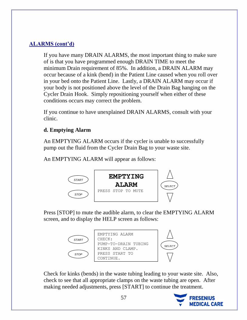
57
ALARMS (cont’d)
If you have many DRAIN ALARMS, the most important thing to make sure
of is that you have programmed enough DRAIN TIME to meet the
minimum Drain requirement of 85%. In addition, a DRAIN ALARM may
occur because of a kink (bend) in the Patient Line caused when you roll over
in your bed onto the Patient Line. Lastly, a DRAIN ALARM may occur if
your body is not positioned above the level of the Drain Bag hanging on the
Cycler Drain Hook. Simply repositioning yourself when either of these
conditions occurs may correct the problem.
If you continue to have unexplained DRAIN ALARMS, consult with your
clinic.
d. Emptying Alarm
An EMPTYING ALARM occurs if the cycler is unable to successfully
pump out the fluid from the Cycler Drain Bag to your waste site.
An EMPTYING ALARM will appear as follows:
START
STOP
EMPTYING
ALARMPRESS STOP TO MUTE
SELECT
Press [STOP] to mute the audible alarm, to clear the EMPTYING ALARM
screen, and to display the HELP screen as follows:
START
STOP
EMPTYING ALARM
CHECK:
PUMP-TO-DRAIN TUBING
KINKS AND CLAMP.
PRESS START TO
CONTINUE.
SELECT
Check for kinks (bends) in the waste tubing leading to your waste site. Also,
check to see that all appropriate clamps on the waste tubing are open. After
making needed adjustments, press [START] to continue the treatment.

58 P/N 470203 Rev. H
ALARMS (cont’d)
If you continue to have unexplained EMPTYING ALARMS, call Technical
Service.
e. Fill Alarm
A FILL ALARM occurs when your programmed FILL TIME has run out
during a Fill, and you have not been filled with the complete programmed
Fill Volume.
A FILL ALARM will appear as follows:
START
STOP
FILL
ALARMPRESS STOP TO MUTE
SELECT
Press [STOP] to mute the audible alarm, to clear the FILL ALARM screen,
and to display the HELP screen as follows:
START
STOP
FILL ALARM
CHECK:
CONES, KINKS, CLAMPS
FILL TIME SETTING.
PRESS START.
SELECT
Make any adjustments needed and press [START] to continue the treatment.
When you restart the treatment, the Fill is repeated from the beginning of the
FILL TIME. When the correct amount of solution has filled you, the
treatment will advance to the Pause or Dwell phase (depending on your
program) even if there is time remaining in the repeated Fill phase.

59
ALARMS (cont’d)
If you have many FILL ALARMS, the most important thing to make sure of
is that you have programmed enough FILL TIME to allow you to fill with
your programmed fill volume. In addition, a FILL ALARM may occur
because of a kink (bend) in the Patient Line caused when you roll over in
your bed onto the Patient Line. Lastly, a FILL ALARM may occur if your
body is not positioned below the level of the solution bags on the cycler
Heater Tray. Simply repositioning yourself when either of these conditions
occurs may correct the problem.
If you continue to have unexplained FILL ALARMS, consult your clinic.
f. Interrupt Too Long
An INTERRUPTED TOO LONG alarm will occur, if you have pressed
[STOP] to INTERRUPT the treatment and have not restarted the treatment
within 10 minutes.
An INTERRUPTED TOO LONG alarm will appear as follows:
START
STOP
INTERRUPT
TOO LONGPRESS STOP TO MUTE
SELECT
Press [STOP] to mute the audible alarm, to clear the INTERRUPT TOO
LONG screen, and to display the HELP screen as follows:
START
STOP
INTERRUPT
TOO LONGPRESS START TO
CONTINUE.
SELECT
You can press [STOP] to INTERRUPT the treatment again, but be aware
that an INTERRUPTED TOO LONG alarm will occur again if you have not
restarted the treatment within another 10 minutes.

60 P/N 470203 Rev. H
ALARMS (cont’d)
g. IQcard Batt Dead
An IQCARD BATT DEAD alarm occurs when the battery in the IQcard is
completely dead.
An IQCARD BATT DEAD alarm will appear as follows:
START
STOP
IQCARD
BATT DEADPRESS STOP TO MUTE
SELECT
Press [STOP] to mute the audible alarm, to clear the IQCARD BATT DEAD
alarm screen, and to display the HELP screen as follows:
START
STOP
IQCARD BATTERY DEAD.
REMOVE THE IQCARD,
INSTALL A NEW BATTERY.
INSTALL THE IQCARD.
PRESS START TO
CONTINUE.
SELECT
Make any adjustments needed and press [START] to continue the treatment.
If you can not replace the dead battery immediately, replace the battery as
soon as you are able to do so, because the cycler will not send information to
an IQcard with a dead battery. Since the cycler stores up to seven treatments
in its internal memory, any of these seven treatments not recorded on the
IQcard while it had a dead battery will be transferred to the IQcard once it
contains a good battery.
h. IQcard Batt Low
An IQCARD BATT LOW alarm occurs when the battery is weak and needs
replacing.

61
ALARMS (cont’d)
An IQCARD BATT LOW alarm will appear as follows:
START
STOP
IQCARD
BATT LOWPRESS STOP TO MUTE
SELECT
Press [STOP] to mute the audible alarm, to clear the IQCARD BATT LOW
alarm screen, and to display the HELP screen as follows:
START
STOP
IQCARD BATTERY WEAK.
INSTALL A NEW BATTERY
SOON. DATA RETENTION
IS UNCERTAIN. PRESS
START TO CONTINUE.
SELECT
Make any adjustments needed and press [START] to continue the treatment.
You will need to return the IQcard to your clinic and get another card to use.
The treatment will be able to continue, and because the cycler records data
for up to 7 days, the treatment data will be saved and then transferred to the
card once it is inserted.
i. IQcard Is In
An IQCARD IS IN alarm occurs if you place an IQcard into the cycler
IQcard slot when IQCARD USED? is set to “NO”.
An IQCARD IS IN alarm will appear as follows:
START
STOP
IQCARD
IS INPRESS STOP TO MUTE
SELECT

62 P/N 470203 Rev. H
ALARMS (cont’d)
Press [STOP] to mute the audible alarm, to clear the IQCARD IS IN alarm
screen, and to display the HELP screen as follows:
START
STOP
IQCARD IS PRESENT.
CHANGE OPTIONS TO
USE IQCARD.
OTHERWISE, THE IQCARD
WILL BE IGNORED. PRESS
START TO CONTINUE.
SELECT
Make any adjustments needed and press [START] to continue the treatment.
If you plan to use the IQCARD to record your treatments, change IQCARD
USED? to “YES”. (See the “ADDITIONAL OPTIONS” section of these
operating instructions for programming IQCARD USED?).
j. IQcard Not In
An IQCARD NOT IN alarm occurs if no IQcard is inserted into the Cycler
IQcard Slot when IQCARD USED? is set to “YES”.
An IQCARD NOT IN alarm will appear as follows:
START
STOP
IQCARD
NOT INPRESS STOP TO MUTE
SELECT
Press [STOP] to mute the audible alarm, to clear the IQCARD NOT IN
alarm screen, and to display the HELP screen as follows:
START
STOP
IQCARD NOT PRESENT.
EITHER INSTALL IQCARD
AND PRESS START OR
PRESS START TO IGNORE.
NO DATA WILL BE
SAVED WITHOUT IQCARD.
SELECT

63
ALARMS (cont’d)
Make any adjustments needed and press [START] to continue the treatment.
If you do not plan to use the IQCARD to record your treatments, change
IQCARD USED? to “NO”. (See the “ADDITIONAL OPTIONS” section of
these operating instructions for programming IQCARD USED?).
k. IQcard Not Initialized
An IQCARD NOT INIT’ED alarm occurs if the cycler senses that there is a
problem with the IQcard.
You will need to return the IQcard to your clinic and get another card to use.
The treatment will be able to continue, and because the cycler records data
for up to 7 days, the treatment data will be saved in the cycler’s memory and
then downloaded when you insert a new card.
An IQCARD NOT INIT’ED alarm will appear as follows:
START
STOP
IQCARD NOT
INIT’EDPRESS STOP TO MUTE
SELECT
Press [STOP] to mute the audible alarm, to clear the IQCARD NOT
INIT’ED alarm screen, and to display the HELP screen as follows:
START
STOP
IQCARD NOT INIT’ED.
REMOVE IQCARD AND
RETURN IT TO CLINIC
FOR REPLACEMENT.
PRESS START TO
CONTINUE.
SELECT
Remove the card, and press [START] to continue the treatment.

64 P/N 470203 Rev. H
ALARMS (cont’d)
l. IQcard Write Protected
An IQCARD WRITE PROTECTED alarm occurs if the cycler senses that
the Write Protect switch on the IQcard is in the “LOCK” position. The
cycler can not write to the IQcard when the IQcard is “locked” (Write
Protected).
An IQCARD WRITE PROTECTED alarm will appear as follows:
START
STOP
IQCARD WRITE
PROTECTEDPRESS STOP TO MUTE
SELECT
Press [STOP] to mute the audible alarm, to clear the IQCARD WRITE
PROTECTED alarm screen, and to display the HELP screen as follows:
START
STOP
IQCARD WRITE
PROTECTED. REMOVE THE
IQCARD. DISABLE THE
WRITE PROTECTION,
INSTALL THE CARD.
PRESS START.
SELECT
Contact Fresenius USA Technical Service for instructions to make any
adjustments needed. Press [START] to continue the treatment.

65
ALARMS (cont’d)
m. Last Bag Alarm
The LAST BAG ALARM sounds just prior to the Last Fill of the treatment
to alert you that it is time to prepare for your Last Fill.
A LAST BAG ALARM will appear as follows:
START
STOP
LAST BAG
ALARMPRESS START TO MUTE
SELECT
Press [STOP] to mute the audible alarm, to clear the LAST BAG ALARM
screen, and to display the HELP screen as follows:
START
STOP
LAST BAG ALARM.
CLOSE CLAMPS ON
SOLUTION LINES.
OPEN CLAMP ON LAST
BAG LINE. PRESS START.
SELECT
Follow the HELP screen instructions and press [START] to continue the
treatment.
n. Valve Cover Open
A VALVE COVER OPEN alarm occurs if the cycler senses that the Pump-
to-Drain valve cover is open when it should not be.

66 P/N 470203 Rev. H
ALARMS (cont’d)
A VALVE COVER OPEN alarm will appear as follows:
START
STOP
VALVE
COVER OPENPRESS STOP TO MUTE
SELECT
Press [STOP] to mute the audible alarm, to clear the VALVE COVER
OPEN alarm screen, and to display the HELP screen as follows:
START
STOP
VALVE
COVER OPENPRESS START TO
CONTINUE.
SELECT
Close the Pump-to-Drain valve cover and press [START] to continue the
treatment.
If you continue to have VALVE COVER OPEN alarms when the Pump-to-
Drain valve cover is closed, call Technical Service.
o. Mid-Drain Alarm
A MID-DRAIN ALARM occurs if you haven’t drained at least one half of
the expected Drain amount prior to one-half of the programmed DRAIN
TIME. For example, if you filled with 2000ml of Solution and your
programmed DRAIN TIME is 20 minutes, you must drain at least 1000ml of
Solution within the first 10 minutes of the Drain phase or a MID-DRAIN
ALARM will occur.

67
ALARMS (cont’d)
A MID-DRAIN ALARM will appear as follows:
START
STOP
MID-DRAIN
ALARMPRESS STOP TO MUTE.
SELECT
Press [STOP] to mute the audible alarm, to clear the MID-DRAIN ALARM
screen, and to display the HELP screen as follows:
START
STOP
MID-DRAIN ALARM
CHECK:
KINKS, CLAMPS,
DRAIN TIME SETTING.
PRESS START.
SELECT
Make any adjustments needed and press [START] to continue the treatment.
When you restart the treatment, the Drain is repeated from the beginning of
the DRAIN TIME. If you have FAST FILL/DRAIN set to “YES”, once you
have drained enough, the treatment will automatically advance to the Fill
even if there is still time remaining in the repeated Drain phase. You can
BYPASS a MID-DRAIN ALARM if there is no chance of you being
overfilled during the next Fill. (See OVERFILL ALARM).
If you have many MID-DRAIN ALARMS, the most important thing to
make sure of is that you have programmed enough DRAIN TIME to meet
the minimum Drain requirement of 85%. In addition, a MID-DRAIN
ALARM may occur because of a kink (bend) in the Patient Line caused
when you roll over in your bed onto the Patient Line. Lastly, a MID-
DRAIN ALARM may occur if your body is not positioned above the level
of the Drain Bag hanging on the Cycler Drain Hook.. Simply repositioning
yourself when either of these conditions occurs may correct the problem.
If you continue to have unexplained MID-DRAIN ALARMS, consult with
your clinic.

68 P/N 470203 Rev. H
ALARMS (cont’d)
p. Mid-Fill Alarm
A MID-FILL ALARM occurs if you haven’t filled with at least one half of
your Fill Volume prior to one-half of the programmed FILL TIME. For
example, if you are programmed to Fill with 2000ml of Solution and your
programmed FILL TIME is 10 minutes, you must fill with at least 1000ml of
Solution within the first 5 minutes of the Fill phase or a MID-FILL ALARM
will occur.
A MID-FILL ALARM will appear as follows:
START
STOP
MID-FILL
ALARMPRESS STOP TO MUTE
SELECT
Press [STOP] to mute the audible alarm, to clear the MID-FILL ALARM
screen, and to display the HELP screen as follows:
START
STOP
MID-FILL ALARM.
CHECK:
CONES, KINKS, CLAMPS,
FILL TIME SETTING.
PRESS START.
SELECT
Make any adjustments needed and press [START] to continue the treatment.
When you restart the treatment, the Fill is repeated from the beginning of the
FILL TIME. When the correct amount of solution has filled your peritoneal
cavity, the treatment will advance to the Pause or Dwell phase (depending
on your program) even if there is still time remaining in the repeated Fill
phase.
If you have many MID-FILL ALARMS, the most important thing to make
sure of is that you have programmed enough FILL TIME to allow you to fill
with your programmed fill volume. In addition, a MID-FILL ALARM may
occur because of a kink (bend) in the Patient Line caused when you roll over
in your bed onto the Patient Line. Lastly, a MID-FILL ALARM may occur

69
ALARMS (cont’d)
if your body is not positioned below the level of the Solution Bags on the
Cycler Heater Tray. Simply repositioning yourself when either of these
conditions occurs may correct the problem.
If you continue to have unexplained MID-FILL ALARMS, consult your
clinic.
q. Not Flushing Alarm
A NOT FLUSHING alarm occurs if the cycler senses a problem during the
Flush Procedure of the treatment set-up phase.
A NOT FLUSHING alarm will appear as follows:
START
STOP
NOT
FLUSHINGPRESS STOP TO MUTE
SELECT
Press [STOP] to mute the audible alarm, to clear the NOT FLUSHING
alarm screen, and to display the HELP screen as follows:
START
STOP
CHECK: CONES BROKEN,
WHITE CLAMPS OPEN,
RED CLAMPS CLOSED.
CORRECT TUBING.
INSTALLATION PRESS
START TO CONTINUE
CONTINUE.
SELECT
Make sure that all of the white clamps are open and the cones are fully
broken on the connected Solution Bag. Also, make sure that there are no
kinks (bends) in the Pump-to-Drain tubing. Lastly, make sure that the
yellow clamp on the pump tubing is fully open and both red clamps are
closed. After you make any needed adjustments, press [START] to continue
the treatment setup.
If you continue to have unexplained NOT FLUSHING alarms, call
Technical Service.

70 P/N 470203 Rev. H
ALARMS (cont’d)
r. No Upload During Treatment
A NO UPLOAD DURING TX alarm will occur if the IQcard is put into the
Cycler after the treatment has started. The treatment has started after the set-
up screen that reads “PLACE BAGS ON SCALE…”
A NO UPLOAD DURING TX alarm screen will appear as follows:
START
STOP
NO UPLOAD
DURING TX
PRESS STOP TO MUTE
SELECT
Press [STOP] to mute the audible alarm, to clear the NO UPLOAD
DURING TX alarm screen, and to display the HELP screen as follows:
START
STOP
CAN’T UPLOAD DURING
TREATMENT. UPLOAD WILL
OCCUR AT TREATMENT
COMPLETION.
PRESS START TO
CONTINUE OR BYPASS.
SELECT
You may leave the IQcard in the Cycler and your treatment will continue
with your current settings. After the treatment is complete, you will be
asked to accept the new treatment settings at that time.
s. Overfill Alarm
An OVERFILL ALARM will occur if the Volume left in your peritoneum
plus the next Fill Volume will be more than 150% (1 ½) of your
programmed CCPD (or FIRST FILL when in Tidal Therapy) Volume. For
example, if your programmed CCPD Volume is 2000ml, an OVERFILL
ALARM will occur if the Volume left in your peritoneum up to the current
point in the treatment, plus the next Fill Volume, is more than 3000ml.

71
ALARMS (cont’d)
An OVERFILL ALARM will appear as follows:
START
STOP
OVERFILL
ALARMPRESS STOP TO MUTE
SELECT
Press [STOP] to mute the audible alarm, to clear the OVERFILL ALARM
screen, and to display the HELP screen as follows:
START
STOP
OVERFILL
ALARMPRESS START TO
CONTINUE.
SELECT
Press [START] to continue the treatment.
When you restart the treatment, the Drain is repeated with the full-
programmed DRAIN TIME. The treatment will not advance to the next
Fill until an adequate amount of additional fluid has been drained from
your peritoneum.
An OVERFILL ALARM can not be BYPASSED.
t. Place Bags on Scale
A PLACE BAGS ON SCALE alarm occurs if you have forgotten to put your
Solution Bags on the Cycler Scale during setup.
A PLACE BAGS ON SCALE alarm will appear as follows:
START
STOP
PLACE BAGS
ON SCALEPRESS STOP TO MUTE
SELECT

72 P/N 470203 Rev. H
ALARMS (cont’d)
Press [STOP] to mute the audible alarm, to clear the PLACE BAGS ON
SCALE alarm screen, and to display the HELP screen as follows:
START
STOP
PLACE BAGS
ON SCALEPRESS START TO
CONTINUE.
SELECT
Place Solution Bags on the Cycler Scale and press [START] to continue the
setup.
u. Priming Alarm
A PRIMING ALARM occurs if the more than 250 ml of fluid loss occurs
during the priming process. This may indicate that there is a fluid leak at the
Solution Bags or the tubing set, or that you connected to the Patient Line
when you shouldn’t have.
A PRIMING ALARM will appear as follows:
START
STOP
PRIMING
ALARMPRESS STOP TO MUTE
SELECT
Press [STOP] to mute the audible alarm, to clear the PRIMING ALARM
screen, and to display the HELP screen as follows:
START
STOP
PRIMING ALARM
CHECK: BAGS/TUBING.
PRESS STOP TO END
CURRENT SETUP –OR–
PRESS START TO
CONTINUE.
SELECT

73
ALARMS (cont’d)
Check the Solution Bags and tubing set for leaks. If you see any leaks, press
[STOP] to end the current setup. You must use new Solution Bags and a
new tubing set to prepare for your treatment.
If you mistakenly connected yourself to the Patient Line, close the blue
clamp on the Patient Line firmly and press [START] to advance to the next
setup screen.
If you continue to have unexplained PRIMING ALARMS, call Technical
Service.
v. Pump Error
A PUMP ERROR alarm occurs if the cycler senses a problem during the
Flush Procedure of the treatment set-up phase.
A PUMP ERROR alarm will appear as follows:
START
STOP
PUMP
ERRORPRESS STOP TO MUTE
SELECT
Press [STOP] to mute the audible alarm, to clear the PUMP ERROR alarm
screen, and to display the HELP screen as follows:
START
STOP
REPLACE TUBING SET
AND SOLUTION BAGS
VERIFY CORRECT
INSTALLATION OF
TUBING SET.
PRESS START.
CONTINUE.
SELECT
Make sure that the pump segment tubing is installed correctly. Also, make
sure that there are no kinks (bends) in the Pump-to-Drain tubing. Lastly,
make sure that the yellow clamp on the pump tubing is fully open and both
red clamps are closed. After you replace the tubing set and the solution
bags, press [START] to continue the treatment setup.

74 P/N 470203 Rev. H
ALARMS (cont’d)
If you continue to have unexplained PUMP ERROR alarms, call Technical
Service.
w. Pump Head Open
A PUMP HEAD OPEN alarm occurs if the cycler senses that the Pump-to-
Drain pump head is open when it should not be.
A PUMP HEAD OPEN alarm will appear as follows:
START
STOP
PUMP HEAD
OPENPRESS STOP TO MUTE
SELECT
Press [STOP] to mute the audible alarm, to clear the PUMP HEAD OPEN
alarm screen, and to display the HELP screen as follows:
START
STOP
PUMP HEAD OPEN ALARM
CHECK:
PUMP HEAD.
PRESS START TO
CONTINUE.
SELECT
Close the Pump-to-Drain pump head and press [START] to continue the
treatment.
If you continue to have PUMP HEAD OPEN alarms when the Pump-to-
Drain pump head is closed, call Technical Service.
x. Pump Leak Alarm
A PUMP LEAK ALARM occurs if the cycler senses unexpected fluid
movement in the drain or waste tubing.

75
ALARMS (cont’d)
A PUMP LEAK ALARM will appear as follows:
START
STOP
PUMP LEAK
ALARMPRESS STOP TO MUTE
SELECT
Press [STOP] to mute the audible alarm, to clear the PUMP LEAK ALARM
screen, and to display the HELP screen as follows:
START
STOP
PUMP LEAK ALARM
CHECK:
DRAIN BAG FOR LEAK.
TUBING IN PUMP.
PRESS START TO
CONTINUE.
SELECT
Close the blue clamp on your Patient Line and check for leaks in the Drain
Bag, Drain tubing, or Waste Tubing. If you find a leak, power the cycler off
then on and follow the Help screens to properly end the treatment.
If you do not find any leaks in the Drain Bag, Drain tubing, or Waste
Tubing, check to make sure that the tubing is properly placed in the Pump-
to-Drain assembly. After you make any needed adjustments, open the blue
clamp on your Patient Line and press [START] to continue the treatment.
If you continue to have unexplained PUMP LEAK ALARMS, call Technical
Service.
y. Scale Alarm
The cycler has one internal Scale that measures fluid movement to and from
the cycler. The cycler Heater Tray and Drain Hook are connected to this
Scale. The cycler continually monitors the Scale and if it detects that fluid is
flowing in the wrong direction or too rapidly, a SCALE ALARM will occur.
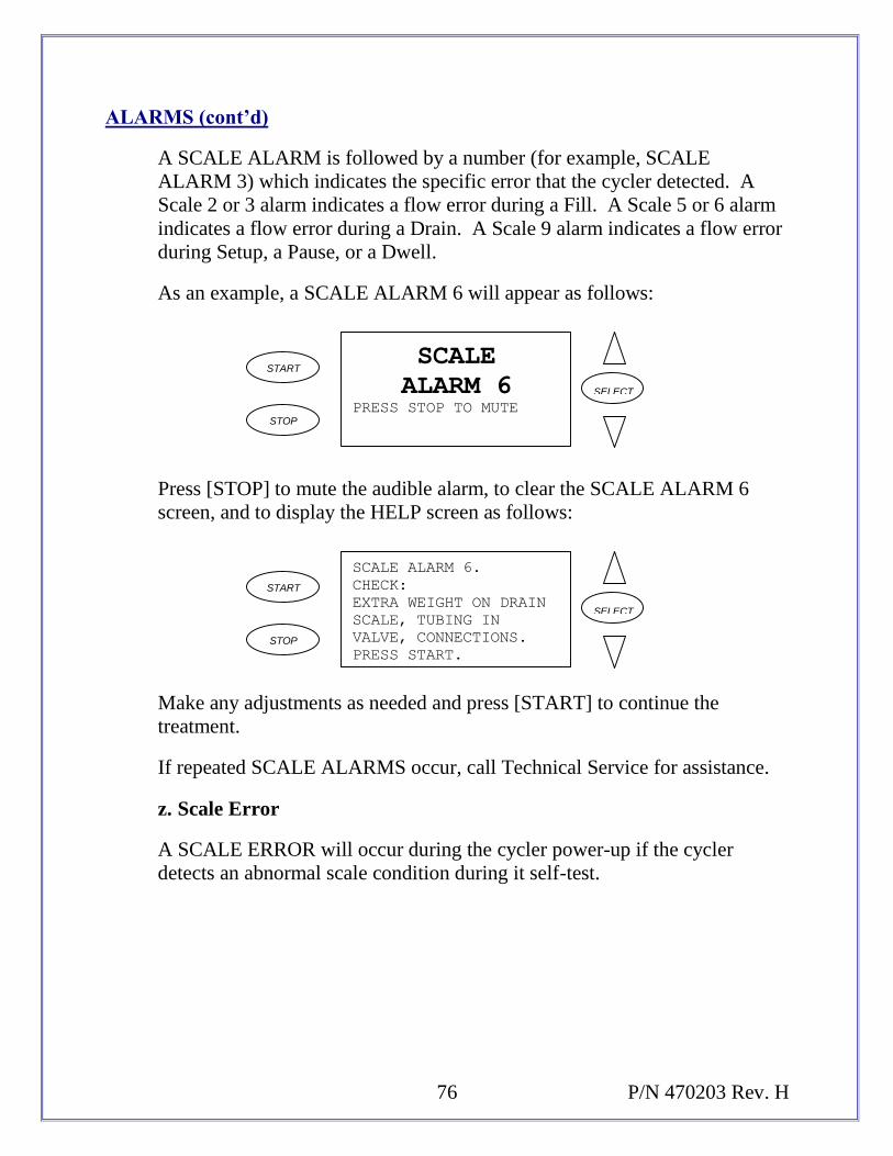
76 P/N 470203 Rev. H
ALARMS (cont’d)
A SCALE ALARM is followed by a number (for example, SCALE
ALARM 3) which indicates the specific error that the cycler detected. A
Scale 2 or 3 alarm indicates a flow error during a Fill. A Scale 5 or 6 alarm
indicates a flow error during a Drain. A Scale 9 alarm indicates a flow error
during Setup, a Pause, or a Dwell.
As an example, a SCALE ALARM 6 will appear as follows:
START
STOP
SCALE
ALARM 6PRESS STOP TO MUTE
SELECT
Press [STOP] to mute the audible alarm, to clear the SCALE ALARM 6
screen, and to display the HELP screen as follows:
START
STOP
SCALE ALARM 6.
CHECK:
EXTRA WEIGHT ON DRAIN
SCALE, TUBING IN
VALVE, CONNECTIONS.
PRESS START.
SELECT
Make any adjustments as needed and press [START] to continue the
treatment.
If repeated SCALE ALARMS occur, call Technical Service for assistance.
z. Scale Error
A SCALE ERROR will occur during the cycler power-up if the cycler
detects an abnormal scale condition during it self-test.

77
ALARMS (cont’d)
A SCALE ERROR alarm will appear as follows:
START
STOP
SCALE
ERRORPRESS STOP TO MUTE
SELECT
Press [STOP] to mute the audible alarm, to clear the SCALE ERROR alarm
screen, and to display the HELP screen as follows:
START
STOP
SCALE
ERRORPRESS START TO
CONTINUE.
SELECT
Most of the time, simply powering the cycler off and then back on will
correct the error.
If repeated SCALE ERROR alarms occur, call Technical Service for
assistance.
aa. Take Bags off Scale
A TAKE BAGS OFF SCALE alarm occurs in most cases if you powered-on
the cycler with full Solution Bags on the Cycler Bag Organizer or Drain
Hook. The Cycler Scale must not have any weight on it during the cycler
power-on self-test.
There are power-on situations when this alarm may not occur, such as after
an electrical power failure in your home. Refer to the IN THE EVENT OF
A POWER FAILURE section of these Operator Instructions for an
explanation of how the cycler functions in an electrical power failure
situation.

78 P/N 470203 Rev. H
ALARMS (cont’d)
A TAKE BAGS OFF SCALE alarm will appear as follows:
START
STOP
TAKE BAGS
OFF SCALEPRESS STOP TO MUTE
SELECT
Press [STOP] to mute the audible alarm, to clear the TAKE BAGS OFF
SCALE alarm screen, and to display the HELP screen as follows:
START
STOP
TAKE BAGS
OFF SCALEPRESS START TO
CONTINUE.
SELECT
Remove all bags from the Cycler Bag Organizer and Drain Hook. Press
[START] to continue the cycler power-on self-test.
If repeated TAKE BAGS OFF SCALE alarms occur and all bags are off the
Cycler Scale, call Technical Service for assistance.
bb. Treatment Setting Corrupted
A TX SETTING CORRUPTED alarm will occur if there is a problem
sensed when the cycler is uploading (reading) the prescription from the
IQcard. Typically when this alarm occurs, you must replace the card.
NOTE: You may see this alarm if your prescription fill volume has been set
for over 3 liters on your IQcard but you did not set ALLOW > 3
LITERS to “YES” in the cycler DIAGNOSTICS OPTIONS
screen. See the “ADDITIONAL OPTIONS” section of these
Operator Instructions for information on setting your cycler to
deliver volumes greater than 3 liters.

79
ALARMS (cont’d)
A TX SETTING CORRUPTED alarm will appear as follows:
START
STOP
TX SETTING
CORRUPTED
PRESS STOP TO MUTE
SELECT
Press [STOP] to mute the audible alarm, to clear the TX SETTING
CORRUPTED alarm screen, and to display the HELP screen as follows:
START
STOP
TX SETTINGS CORRUPTED.
IQCARD WILL NOT
ADJUST THE TREATMENT
SETTINGS. PROGRAM
YOUR CYCLER MANUALLY.
PRESS START.
SELECT
Using the prescription sheet your clinic nurse gave to you, manually
program your cycler and go on with your treatment.
If you leave the card in and press [START], the cycler will attempt to write
to your card. If the card can be written to, then at the end of your treatment
your treatment data will be written to the IQcard.
Replace the corrupted IQcard as soon as possible.
cc. Warming Alarm
A WARMING alarm will occur just prior to your first Fill if the cycler
detects that the Dialysis Solution is not warm enough. The Solution may not
be warm enough because adequate Solution PREWARMING time did not
occur, or because the cycler Heater Switch is off.

80 P/N 470203 Rev. H
ALARMS (cont’d)
A WARMING alarm will appear as follows:
START
STOP
WARMINGSOLUTION TEMPERATURE
TOO COLD.
PRESS START TWICE
TO BYPASS.
SELECT
If you decide to continue with cool Solution, you will have to BYPASS this
alarm. If you would rather continue when the Solution is warmer, turn on
the cycler Heater Switch if it is off, and leave the cycler at the WARMING
alarm screen. BYPASS the alarm when you are ready to continue your
treatment.
dd. Zero Fill Volume Alarm
A 0 FILL VOL ALARM occurs when you have exited the SETTINGS
screen with one or more of the Fill Volumes set to “0” (with the exception of
LAST FILL).
A 0 FILL VOL ALARM will appear as follows:
START
STOP
0 FILL VOL
ALARMPRESS STOP TO MUTE
SELECT
Press [STOP] to mute the audible alarm, to clear the 0 FILL VOL ALARM
screen, and to display the HELP screen as follows:
START
STOP
ZERO FILL VOL ALARM.
RETURN TO SETTINGS OR
TIDAL SETTINGS AND
VERIFY FILL VOLUMES.
PRESS START TO
CONTINUE.
SELECT

81
ALARMS (cont’d)
Press [START] then [SELECT] to enter the SETTINGS screen. Review the
TIDAL SETTINGS menu to make sure that the correct therapy and volumes
are programmed.
Press [START] to return to the SETTINGS screen and review the PAUSE,
CCPD (or FILL), and LAST FILL Volumes to make sure that they are
correct. Once you make all needed corrections, press [START] to return to
the STANDBY screen.

82 P/N 470203 Rev. H
16. ABANDON TREATMENT ALARMS
Abandon Treatment alarms occur when the cycler detects a condition that requires
you to stop the treatment and to power off the cycler. An Abandon Treatment
alarm will specify the condition that the cycler detected and display a message
requiring you to “TURN MACHINE OFF”.
The Abandon Treatment alarms are:
BAT RAM ALARM THERM 2B ALARM
EPROM ERROR THERM 3 ALARM
HEATER ALARM THERM 3B ALARM
PTD ALARM VOLTAGE ALARMS
SCALE OUT OF RANGE VALVE ERROR
THERM 2 ALARM WATCHDOG ALARM
If an Abandon Treatment alarm occurs you should:
clamp the temporary blue clamp on the Newton IQ Set Patient Line,
write down all the information displayed on the alarm screen,
power off the cycler and,
call Fresenius USA Technical Service for assistance.
There are two preventable Abandon Treatment alarms. By taking the following
steps, you might be able to prevent these alarms:
Therm 2, 2b, 3, Or 3b Alarm (Temperature Alarms) – make sure that
there are no heating or air conditioning vents, or fans directly over the
Solution Bags resting on the Cycler Bag Organizer. Also, if you need only
one Solution Bag for your treatment, place the single bag in the center of the
Cycler Bag Organizer.

83
ABANDON TREATMENT ALARMS (cont’d)
Scale Out Of Range Alarm – the maximum allowable combined weight on
the Newton IQ Cycler scale is 39,500 grams (39.5 liters). The combined
weight on the Scale consists of the cycler Heater Tray, Bag Organizer,
Dialysis Solution Bags, Drain Hook, and Drain Bags. You can avoid
causing a SCALE OUT OF RANGE ALARM by:
placing only the amount of Dialysis Solution necessary to perform
your treatment on the Heater Tray/Bag Organizer at the start of the
treatment
not leaning or placing any foreign article(s) on the Heater
Tray/Bag Organizer and,
not pulling down forcefully on the Drain Hook.

84 P/N 470203 Rev. H
17. IN THE EVENT OF A POWER FAILURE
If a power failure occurs (or if the power switch is turned off) while the Newton IQ
Cycler is at the Standby screen, the cycler will perform its normal power-up
routine when power is restored.
If a power failure occurs (or if the power switch is turned off) while the Newton IQ
Cycler is at any screen other than the Standby screen, the cycler will close any
open valve, stop the pump if it is rotating, and turn off the display. When power is
restored, the Newton IQ Cycler will sound an alarm. Pressing the [STOP] key will
mute the alarm and display a Help screen allowing you to choose to resume the
current treatment from where it was interrupted, or start an entirely new treatment.
If a power failure occurs during the setup, the screen will prompt the user to restart
the procedure. Be sure to read and follow the screen prompts carefully.

85
18. DESCRIPTION
The Newton IQ Cycler consists of a Control Unit, a Pump-to-Drain assembly, and a Stand.
Control Unit - The Control Unit consists of a Heater/Scale assembly and a Front Control Panel.
Heater/Scale Assembly – The cycler Heater holds, and warms Dialysate Solution
Bag(s). Up to 20 liters of Solution can be placed on the Heater surface. The cycler
contains a single Scale that weighs fluid delivered to and drained from the patient. The
Scale monitors weight placed on the Heater Surface located at the top of the cycler and
on the Drain Hook located at the underside of the cycler.
Front Control Panel – The cycler Front Panel has a Display Screen and five Control
Buttons. The Screen displays text providing cycler setup, treatment, and alarm
instructions/information. The five Control Buttons are used for programming and
operating the cycler. The five Control Buttons function as follows:
[START] – is used to advance through the normal exchange sequence. It also
permits bypassing, when pressed twice in rapid succession.
[STOP] – is used to mute an alarm or interrupt the treatment.
[SELECT], the [UP] arrow, and the [DOWN] arrow – are used to program
the cycler.
Pump-to-Drain Assembly – The Pump-to-Drain Assembly plugs into the Cycler Control Unit
and mounts to the middle of the Cycler Stand. The Pump-to-Drain consists of two adjacent
solenoid valves. The front solenoid valve opens to permit fluid to flow from the Cycler Fresh
Dialysis Solution Bags to the patient. The rear solenoid valve opens to permit fluid to flow from
the patient to the Cycler Drain Bags. The Pump-to-Drain also contains a peristaltic pump that
rotates to empty effluent from the patient drain bag to a waste site. The Pump-to-Drain is
controlled electronically by the Cycler Control Unit.
Cycler Stand – The Cycler Stand consists of a Base with locking castors, a two-part vertical
Support Pole, a Pump-to-Drain mounting bracket, a horizontal Cycler Hanger Rod, and a
manifold holder. The Cycler Stand serves as a support frame for the Cycler Control Unit and
Pump-to-Drain Assembly.

86 P/N 470203 Rev. H
19. GLOSSARY OF TERMS
Diurnal- Daytime
Flush- Procedure to remove air and potential contaminates from bag lines and
connections
Manifold- Round white disk on the cycler tubing
Manifold Holder- Used to hold the tubing during the flush procedure, tubing is
placed with single-line up, 4 lines hanging down
Prime- Procedure to remove air from the tubing line that connects to the patient’s
catheter
Pump-to-Drain- This pumps the used fluid from the bag hanging below the
cycler to a drain receptacle

87
20. SPECIFICATIONS
Dimensions: Control Unit: 10”H x 12”D x 15”W
Stand: 45”H x 22.5”D x 20”W
Weight: Control Unit: 25 pounds (14kG) Approx.
Stand: 5 pounds (2.2kG) Approx.
Power Requirements: 117V 10%, 60Hz
Electrical Requirements: 3 Amp Grounded Plug and Receptacle
Current Leakage: Under 100 microamperes
Number of Fills: 1 – 20 (Exchanges)
Fill Volume: 500 – 4000ml
Last Fill Volume: 0 and 50 – 4000ml
Fill Time: Variable from 1 – 59 minutes
Dwell Time: Variable from 5 minutes to 9 hours 55 minutes
Drain Time: Variable from 1 – 59 minutes
Temperature: Fixed at 37C 2C
Product Improvement Policy
The Newton IQ machine was designed and built to comply with these product specifications. It is the
intention of Fresenius Medical Care to continuously engage in product development that may result in
modifications or improvements to specifications or equipment produced in the future. Such product
improvements shall not incur any obligation to make similar changes or improvements to equipment
previously produced. These changes or improvements may or may not be applicable or usable with
previously produced equipment. Where possible, improvements will be made available at reasonable
prices. Any such improvement shall not be construed as corrections of any deficiency in previously
produced equipment.

88 P/N 470203 Rev. H
21. MAINTENANCE
Service and maintenance must be performed by a qualified person.
Surface cleaning of all Cycler components should be carried out on a per-treatment basis
using a damp cloth and a dilute (1:100) bleach solution (1 part bleach to 100 parts water)
or other surface disinfectant.
Do NOT use any disinfectant containing alcohol.
Do NOT use spray bottles.
Do NOT use foaming type cleaners on surfaces of the machine.
Clean up spills immediately.
The condition of the Cycler Stand should be checked periodically for:
binding or damaged wheels,
loose wheel fasteners,
cracked base or welds,
bent or dented legs or poles,
loose or missing plastic leg end caps, and
pole joints that are wobbly or can be rotated with the hitch pin inserted.
If any of these problems are found, do not use the Cycler Stand or attempt to repair it.
For further maintenance questions, please contact:
Fresenius USA
4040 Nelson Avenue Concord, CA 94520
Telephone:
(800) 227-2572 or (925) 288-4218
89
WARNINGS AND PRECAUTIONS
WARNING! Check the Heater Tray and Bag Organizer to be sure they are free of
obstructions and do not touch the top of the Cycler Cabinet or the Stand
Pole. Interference with the Heater Tray may result in inaccurate weighing
of Dialysis Solution, and possibly result in patient injury. Check again
when all Solution bags are on the scale.
WARNING! If the screen on your machine displays “T & C Mode” do not use the
machine and call Technical Service for a replacement of the machine.
WARNING! Check and make sure the Manifold Holder does not come in contact with
the Bag Organizer, this may result in inaccurate weighing of Dialysis
Solution, and may possibly result in injury
WARNING! It is possible to program the Cycler to fill with more than 3,000 ml. Do
not fill with more than instructed by your physician.
WARNING! Check the new prescription to be transferred from the IQcard to the Cycler
carefully. If your name is not displayed, or the proposed prescription is
not correct, do not accept the settings.
WARNING! The Cycler Stand could potentially tip over and cause injury to the patient
or bystanders if a Cycler and Stand is used in a tilted position or if moved
without appropriate care. Never place objects under the Cycler Stand
wheels to level the stand!
WARNING! When the bags are in the Bag Organizer, check the Heater Tray and Bag
Organizer to be sure they are free of obstructions and do not touch the top
of the Cycler Cabinet or the Stand Pole. Interference with the Heater Tray
may result in inaccurate weighing of Dialysis Solution, and possibly result
in patient injury.
WARNING! The peritoneal dialysis Cycler may be subject to electromagnetic or
electrostatic interference (EMI or ESD), causing false alarms and/or
shutdown of the machine. Devices emitting electromagnetic radiation
such as microwave ovens, portable phones, radio equipment (walkie
talkies, etc.), radio transmitters, and like equipment should not be used
close to this equipment. The operator should monitor the function of the
machine and remove unnecessary equipment from the treatment area
should the Cycler be affected. Home patient should be aware of large
overhead power lines or electrical substations that may generate large
electromagnetic fields.
CAUTION! Do not lift the Cycler with the Heater Tray/Scale. Doing this may damage
the Cycler Scale.

90 P/N 470203 Rev. H
WARNINGS AND PRECAUTIONS (cont’d)
CAUTION! The Newton IQ Cycler is a computer controlled electromechanical
medical device. The Newton IQ Cycler should be installed in an
appropriate environment (indoors) free from extremes of temperature and
humidity reasonably protected from dust and dirt contamination or liquid
splashes. Failure to install the Newton IQ Cycler according to these
guidelines may result in improper operation or early failure of the device
or its components.
CAUTION! Use only Cycler tubing sets intended for Fresenius Newton IQ Cycler.
CAUTION! Maximum total weight on the Cycler load cell Scale is 39,500 grams
(39.5 liters).
CAUTION! Overloading the Scale can cause damage to the Cycler load cell.
CAUTION! The Fresenius Newton IQ Cycler should be moved by pulling on the
Cycler Stand vertical Pole, or the Cycler Stand horizontal Hanger Rod,
not the Control Unit.

91
WARNINGS AND PRECAUTIONS (cont’d)
Precautions:
Federal (USA) law restricts this device to sale only by or on the order of a physician. Frequency,
duration, and treatment parameters are to be determined by the prescribing physician.
Warnings:
These instructions are for the Fresenius USA, Inc. Newton IQ Cycler peritoneal dialysis
exchange device. The machine must be operated in accordance with these instructions. All
operators of this machine must be thoroughly trained and must read this entire manual and any
applicable appendices before using the Newton IQ Cycler.
The Newton IQ Cycler is not intended for pediatric use, or for use with patients requiring fill
volumes of less than 500ml.
Aseptic technique to prevent infection is required with all peritoneal dialysis procedures.
The electrical source must be a single phase, three conductor type plug. The proper polarity and
ground integrity must be initially checked and thereafter maintained. Failure to do so may result
in electrical shock to the patient or operator.
Shock hazard. Do not remove the cover. Refer servicing to qualified personnel.
Replace fuses only with the same type and rating.
Indications:
The Fresenius Newton IQ Cycler is indicated for acute and chronic peritoneal dialysis. The following
therapies are supported: continuous cycling peritoneal dialysis (CCPD), intermittent peritoneal dialysis
(IPD), tidal peritoneal dialysis (TPD), and PD Plus peritoneal dialysis (CCPD + daytime exchange
delivered from the Cycler).
Contraindications:
CAPD and CCPD are effective and attractive choices for many ESRD patients; however, no one
dialysis therapy is intended for all patients. When assessing peritoneal dialysis as a therapy in
such situations, the benefits to the patient must be weighed against the possible complications.
Transdiaphramatic leakage, hypercatabolism, and insufficient surface area are generally
considered to be contraindications to automatic cycling therapy.

92 P/N 470203 Rev. H
WARNINGS AND PRECAUTIONS (cont’d)
Side Effects:
Peritoneal dialysis therapy occasionally causes adverse patient reactions. Abdominal pain,
bleeding, peritonitis and catheter obstruction can cause problems with the treatment.
Hypovolemia, hypervolemia, hypotension, edema or muscle cramping can occur if improper
dialysate solutions are used. The patient’s weight and general physical status, including serum
chemistry levels, must be routinely monitored as part of the dialysis treatment in order to
maintain correct fluid removal and prevent such complications as congestive heart failure,
volume depletion, shock, and inadequate therapy. Strict adherence to physician prescription for
therapy is required to help prevent many of the physiological reactions to dialysis treatment.

93
22. LIMITED WARRANTY
SALE of the machine or parts described or referenced herein is expressly conditioned upon the terms and
conditions set forth below. Any additional or different terms or conditions set forth by the Purchaser to
Fresenius USA, Inc., (herein called “the Company”) shall not be effective or binding, and the terms set
forth herein shall not be modified or amended, unless assented to in writing by an authorized official of
the Company located in California.
Concord,
LIMITED WARRANTY: The Company warrants to the Purchaser that the equipment delivered is free
from defects in material or workmanship for the periods specified below, provided the equipment is used
and maintained in accordance with the original manufacturer’s operating instructions:
A. Mainframe chassis, and electronic components, lamps, etc. shall be warranted for ninety (90)
days from the date of initial installation or one hundred and eighty (180) days from the
shipment, whichever is first.
B. Consumables shall not be warranted.
The Company will repair or replace, at its option, using new or reconditioned parts and/or assemblies, any
parts subject to this warranty which are proven defective in materials or workmanship. Such repair and
replacement will be made without cost to the Purchaser, and the Company reserves the right to determine
the location at which the repair or replacement will be accomplished. The Warranty does not apply to any
equipment which is misused, abused, neglected, tampered with, damaged by accident, flood, fire, or other
hazard, subjected to abnormal or unusual electrical or fluid stress, improperly installed or operated, or not
maintained in accordance with the routine maintenance schedule set forth in the operating manual for the
equipment.
THE FOREGOING WARRANTY SHALL BE IN LIEU OF ANY OTHER WARRANTIES,
EXPRESSED, IMPLIED, OR STATUTORY, RESPECTING THE EQUIPMENT OR ANY PARTS OR
COMPONENTS THEREOF, AND THE COMPANY MAKES NO IMPLIED WARRANTY OF
MERCHANTABILITY OR FITNESS FOR A PARTICULAR PURPOSE. THE PURCHASER’S SOLE
AND EXCLUSIVE REMEDY IN CONTRACT, TORT, OR UNDER ANY OTHER THEORY
AGAINST THE COMPANY RESPECTING THE EQUIPMENT AND ITS USE SHALL BE THE
REPLACEMENT OR REPAIR OF THE EQUIPMENT AND ITS PARTS AS DESCRIBED ABOVE,
AND NO OTHER REMEDY (INCLUDING, WITHOUT LIMITATION, CONSEQUENTIAL
DAMAGES) SHALL BE AVAILABLE TO THE PURCHASER. The company shall have no further
obligation or liability with respect to the equipment or its sale, operation and use, and the Company
neither assumes, nor authorizes the assumption of, any obligation or liability in connection with such
equipment.
TERMS: Net 30 days, FOB shipping point plus sales and similar taxes. The Company’s prices do not
include sales, use, excise, or similar taxes. Consequently, in addition to the prices specified herein, the
amount of any present or future sales, use, excise, or other similar tax applicable to the or use of the
equipment hereunder shall be paid by the Purchaser, or in lieu thereof, the Purchaser shall provide the
Company with a tax exemption certificate acceptable to the taxing authorities.
REFER ALL SERVICING AND INFORMATION REQUESTS TO:
Fresenius USA, Inc. 4040 Nelson Avenue Concord, CA 94520 Telephone: (800) 227-2572
