next-generation, packet-based transport networks economic ... · fujitsu network communications...
TRANSCRIPT

Next-Generation, Packet-Based Transport Networks Economic Study

FUJITSU NETWORK COMMUNICATIONS INC.2801 Telecom Parkway, Richardson, Texas 75082-3515Telephone: (972) 690-6000(800) 777-FAST (U.S.)us.fujitsu.com/telecom
1
IntroductionThe accelerating growth of packet-based services such as Ethernet is well documented. Almost all new emerging services such as VoIP and Internet IPTV are packet-based. The clear trend that has emerged is that an ever-increasing amount of service provider network traffic will be packet-based.
Current CTNs are primarily SONET/SDH-based. With the accelerating growth of packet-based services, these networks have been enhanced with technologies such as VCAT, G.7041 GFP packet encapsulation over SONET/SDH/PDH, and G.7042 LCAS, which can be used to dynamically adjust VCAT bandwidth as packet service bandwidth increases. These technologies are enabling SONET/SDH transport networks to better address packet service applications.
However, important issues remain. Packet-based service instances are bursty and do not require dedicated transport bandwidth. Many packet-based service instances are best effort and are amenable to a high degree of statistical multiplexing. Only CBR circuit emulation service requires dedicated bandwidth. In theory, the statistical multiplexing gain that can be realized by using packet-based transport for packet services should translate to network cost savings.
Channelized circuit switched transport does not result in the most efficient and cost-effective interfaces on packet service switches (often called MSEs). Such interfaces are typically very expensive. For packet services, packet-based subscriber service port/service instance aggregation should be much more efficient and cost-effective.
The use of virtual concatenation in circuit switched transport provides a reasonable degree of granular bandwidth allocation for packet-based service demands. However, packet-based transport supports transport bandwidth allocation to any granularity, without any restrictions based on a circuit switched multiplexing hierarchy.
This paper investigates the potential advantages of packet-based transport by providing a quantitative economic comparison between the CTN and the PTN. It also addresses three economic metrics, CAPEX, transport capacity efficiency, and OPEX. Quantitative measures are developed for the first two metrics. OPEX is considered on a more general basis, however, a relevant publicly available MEF quantitative study is summarized.
A typical metro network is modeled on the basis of using either circuit switched or packet-based transport. These two metro networks are compared for two different sets of customer traffic demands. The comparison parameters are normalized network implementation cost, collector and IOF ring service bandwidth, and number of core network access ports. This yields a CAPEX and transport capacity comparison.
Like SONET/SDH, packet-based transport should be connection orientated, support multiple services, and be standards-based. Also like SONET/SDH, it should afford the opportunity to perform traffic engineering and to groom service instances that share common attributes into trunks. MPLS pseudowire is the only current (non-legacy) standards-based technology that addresses all of these requirements.
For your convenience, a list of acronyms can be found at the end of this document.

FUJITSU NETWORK COMMUNICATIONS INC.2801 Telecom Parkway, Richardson, Texas 75082-3515Telephone: (972) 690-6000(800) 777-FAST (U.S.)us.fujitsu.com/telecom
2
Packet transport networks can be implemented by using IEEE 802.1 standard VLAN bridges. However, such networks are connectionless and only support Ethernet and possibly circuit emulation services. For these reasons, transport networks should be connection orientated. In order to provide multipoint Ethernet service over MPLS pseudowire-based packet transport, it is necessary to use 802.1AD provider bridges at the edge of the network, and in large service network applications, in the core of the network. However, the underlying packet transport technology is MPLS pseudowire.
Based on this scenario, the economic analysis provided by this paper uses an MPLS pseudowire-based network model. Subsequent sections will provide a brief overview of MPLS pseudowires, a description of the CTN and the PTN models, quantitative economic analysis, results for two sets of customer traffic demands, and a concluding summary.
Pseudowire OverviewA pseudowire provides a bidirectional connection of two service ports (e.g. Ethernet, ATM, Frame Relay) of the same type across an underlying packet-switched network. It emulates the essential attributes of a point-to-point connection (e.g., a wire) of a telecommunications service over a packet switched network. The PSN, which provides transport for pseudowires, can either be MPLS- or IP-based. A pseudowire is carried in a PSN tunnel, which is similar to a TDM trunk. The underlying PSN tunnel is a trunk that aggregates multiple pseudowires. For the PTN, the most appropriate pseudowire tunnel mechanism is an MPLS-based tunnel. Pseudowire demultiplexing is accomplished by an MPLS label. A pseudowire over an MPLS tunnel constitutes a two-label MPLS stack.
The IETF is developing the initial set of standards for pseudowires in the PWE3 Work Group. The focus of this work has been to support additional services over IP networks. ITU SG 15 has recently started work on a new Recommendation G.8010.1, “Application of MPLS in the Transport Network”. It is believed that MPLS-based packet transport only requires a subset of IETF-specified MPLS and pseudowire technology. G.8010.1 will specify this subset.
Figure 1 provides a pseudowire reference model.

FUJITSU NETWORK COMMUNICATIONS INC.2801 Telecom Parkway, Richardson, Texas 75082-3515Telephone: (972) 690-6000(800) 777-FAST (U.S.)us.fujitsu.com/telecom
3
PE1 PE2
PSN
PSN Tunnel
Emulated Service
Pseudowires
CE1 CE2
AttachmentCircuits
AttachmentCircuits
Figure 1: Pseudowire Reference Model
A pseudowire interconnects two attachment circuits of a chosen service across a PSN. An attachment circuit is a physical or virtual circuit, which connects a CE node to a PE node. An attachment circuit can be an Ethernet port, a VLAN, a Frame Relay or ATM virtual circuit, a DS1, DS3, or a SONET STS-3.
Pseudowires, which are carried by PSN tunnels, are similar in concept and application to SONET OC-3 and OC-12 paths that are carried in OC-48/OC-192 trunks. The PSN tunnel that carries pseudowires is similar to the SONET line layer. The link layer (e.g. Ethernet, SONET, DWDM) that transports the PSN tunnel is similar to the SONET section layer. Figure 2 shows the analogy.
PathLayer
• Payload transport between TE/PE• Maps payloads into format required by Line/Tunnel layer
• Transport of STS-N frames or Pseudowire packets across the physical medium
• The Physical layer deals with the transport of bits as optical or electrical pulses across the physical medium
• Provides transport of Path payloads across physical layer or data link layer• Multiplexes OC-M to OC-N or pseudowires into PSN tunnels
LineLayer
SectionLayer
PhysicalLayer
PseudowireLayer
Ethernet/ATM/FRPayload
DS1/DS3Payload
PSN TunnelLayer
Data LinkLayer
(Ethernet)
PhysicalLayer
Figure 2: Pseudowire and SONET Layer Analogy

FUJITSU NETWORK COMMUNICATIONS INC.2801 Telecom Parkway, Richardson, Texas 75082-3515Telephone: (972) 690-6000(800) 777-FAST (U.S.)us.fujitsu.com/telecom
4
In order to aggregate client payload signals with similar service properties, pseudowires can be groomed from one MPLS tunnel to another. Pseudowires which extend over multiple MPLS tunnels are known as multi-hop pseudowires. In addition to the demultiplexing label, certain pseudowire applications may require an optional four byte control word. The control word is used to carry per-packet information, and it is used at the egress for service frame reconstruction. It encodes information such as packet sequence numbers (to insure in sequence delivery) and time stamps for circuit emulation.
Generic Metro Transport Network ModelTo understand the economic impact of the packet-based transport, a metropolitan area network model that simulates a potential real world green field deployment of a today’s telecommunication service provider was established. The generic metro transport network model consists of a set of collector rings, which access customer sites, and an IOF ring, which interconnects the collector rings and connects these rings to the core network. In this model, there are four COs which serve as the IOF, and which are equipped with IOF NEs for service transport over an OC-192 SONET ring. Each IOF CO is connected to CPE through two SONET OC-48 collector rings, which interconnect four remote offices that are equipped with edge NEs. Figure 3 illustrates the generic metro transport network model. All collector rings are the same. The details are only shown for one IOF CO. One IOF CO connects customer service interfaces to service switches at the edge of the core network. For the CTN, IOF and collector ring NEs are SONET MSPPs. For the PTN, the collector ring NEs are modeled as PEDs, and the IOF NEs are modeled as PADs. Subsequent sections will provide more details on the PED and PAD. The service switches are modeled as a MSEs and a core data switch.
DS1/DS3 Fast Ethernet/GigE
MSE
IOF RingOC-192
Collector Ring OC-48
Collector Ring OC-48
DS1/DS3
Fast Ethernet/GigE
DS1/DS3
Fast Ethernet/GigE
CoreData
Switch
Data Core
IOFNE
IOFNE
IOFNE
EdgeNE
EdgeNE
EdgeNE
CPE
DS1/DS3
Fast Ethernet/GigECPE
CPE
DS1/DS3 Fast Ethernet/GigE
CPE
DS1/DS3Fast Ethernet/GigE
CPE
CPE
DS1/DS3Fast Ethernet/GigE
CPE
IOFNE
EdgeNE
EdgeNE
Figure 3: Generic Metro Transport Network

FUJITSU NETWORK COMMUNICATIONS INC.2801 Telecom Parkway, Richardson, Texas 75082-3515Telephone: (972) 690-6000(800) 777-FAST (U.S.)us.fujitsu.com/telecom
5
Customer interfaces are a combination of DS1, DS3, 10/100 Mbps Fast Ethernet, and GigE ports. Network protection is provided by the SONET UPSR mechanism in the collector and IOF rings. For the core network access point connection between the IOF NE and the MSE, 1+1 protection is used for either channelized OC-12 or GigE interfaces. On the client side, DS1 and DS3 interfaces are 1:1 protected and the Ethernet interfaces are unprotected.
Description of the Circuit Switched and Packet-based Network ModelsTwo network architectures will be applied to this metro access network model for comparison. The first architecture is the CTN, which is based on an MSPP. An edge MSPP is used as an edge NE in the edge sites of the collector rings and a core MSPP as an IOF NE for the IOF COs in the IOF ring. The edge MSPP has interfaces for DS1, DS3, Fast Ethernet and GigE client services and OC-48 for network connectivity. Its switch fabric can groom STS-1 and VT1.5 levels of traffic. The core MSPP has the capability of multiple OC-48 and OC-192 ring termination, and grooming capability at both STS-1 and VT1.5 levels. Ethernet and OC-12 interfaces are used on the core access MSPP for handoff of traffic to the core network through the MSE.
The second architecture is a packet-based transport network with PEDs in the collector ring as the edge NEs, and PADs in the IOF ring as the IOF NEs. PEDs and PADs support the same interfaces as the MSPPs. PEDs encapsulate client signals in pseudowires. In addition, they perform traffic management, which is appropriate for the service attributes of the client signal. They also set and process pseudowire control word parameters. For the customer traffic flows used in this paper, the PED encapsulates Ethernet and IP/PPP/HDLC client signals into pseudowires. These MPLS pseudowires are GFP-mapped into SONET STS-n frames.
PADs provide four primary functions:1) Switch collector ring MPLS traffic to the interoffice ring;2) MPLS tunnel level processing, traffic management, and forwarding;3) Groom pseudowires with common service attributes into MPLS tunnels with similar attributes;4) Hand-off customer service instances over pseudowire-aggregated MPLS trunks to the MSE.
Customer Traffic Matrix-1—Analysis and ResultsThe first customer traffic matrix consists of all data demands: IP/PPP and Ethernet. IP/PPP is carried over DS1, 4xDS1 and DS3. The Ethernet demand is either Fast Ethernet ports with a PIR of 20 Mbps and GigE ports with a PIR of 200 Mbps. For the IP/PPP demands, the service applications are either Internet access or CPE to CPE private line. For the Ethernet ports, the service applications are TLS and Internet access. The traffic flow is to/from a CPE, through an edge NE, to the collector ring and into one of the IOF NEs. From there, it is either directly switched to another CPE through the same or a different IOF CO, or it crosses the IOF network for access to the core network through the MSE. It is assumed that approximately 15% of the traffic is transported between the CPEs of collector rings under the same IOF CO, and approximately 15% of the traffic is transported to CPEs associated with collector rings under other IOF COs. The remaining 70% of the traffic is transported to the core network. In terms of transport bandwidth requirements, the traffic mix for the first study is about 50% DS1/4×DS1/DS3 and 50% Fast Ethernet/GigE. See Table 1.

FUJITSU NETWORK COMMUNICATIONS INC.2801 Telecom Parkway, Richardson, Texas 75082-3515Telephone: (972) 690-6000(800) 777-FAST (U.S.)us.fujitsu.com/telecom
6
DS1
TDM=50% Ethernet=50%
Edge NE Site 1Edge NE Site 2Edge NE Site 3Edge NE Site 4
BW Split
56141414
1099
365
422
2
11
4 x DS1 DS3 FE-20M GE-200M
Table 1: Traffic Demands Requirement Per Collector Ring
In designing the CTN, edge MSPPs are deployed for edge NEs, and IOF MSPPs are used for IOF NE. Since point-to-point DS1 demand exits, DS1 or VT1.5 level of grooming and aggregation capability is required in both edge and IOF MSPPs. The IOF MSPP, which acts as the aggregation point for access to the core network, requires a much larger VT1.5 fabric. Both the collector ring and IOF MSPPs provide UPSR network protection. The network design and traffic routing is illustrated in Figure 4.
For the Fast Ethernet demands, the 20 Mbps PIR is routed over an STS-1. The remaining STS-1 bandwidth will only be used if the customer requests a bandwidth upgrade. For the GigE demands, the 200 Mbps PIR is routed over a virtual concatenation of four STS-1s. For the CTN, Figure 4 shows the total number of collector ring STS-1s and IOF ring STS-1s required to support customer demands. Each collector ring has been packed with 46 STS-1s, subsequently, an OC-48 is required with a utilization of 96%. The total number of IOF STS-1s is 316. This requires the use of two OC-192 rings for IOF transport. The utilization of these rings is 83%.
The IOF MSPP that connects to the core network aggregates DS1/DS3 traffic into eleven channelized OC-12 interfaces to the MSE. It also connects a subset of the customer Fast Ethernet and GigE demands to the MSE.
MSE
1276 DS1s (76%) and 80 DS3s (71%)are aggregated into 11 channelizedOC-12s. Also 10 Fast Ethernet and
5 GigE for Ethernet traffic.
1 x OC-482 x OC-192
1 x OC-48
GE
CoreRouter
IOFMSPP
IOFMSPP
IOFMSPP
EdgeMSPP
EdgeMSPP
EdgeMSPP
EdgeMSPP
EdgeMSPP
IOFMSPP
48 STS-1s provisionedfor all DS1/DS3/Fast Ethernet/
GigE traffic from onecollector ring
316 total STS-1srequired to carry trafficfrom all collector rings
Figure 4: Network Design for the CTN Scenario
FUJITSU NETWORK COMMUNICATIONS INC.2801 Telecom Parkway, Richardson, Texas 75082-3515Telephone: (972) 690-6000(800) 777-FAST (U.S.)us.fujitsu.com/telecom
7
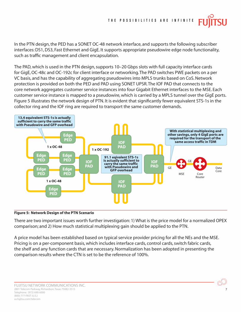
In the PTN design, the PED has a SONET OC-48 network interface, and supports the following subscriber interfaces: DS1, DS3, Fast Ethernet and GigE. It supports appropriate pseudowire edge node functionality, such as traffic management and client encapsulation.
The PAD, which is used in the PTN design, supports 10–20 Gbps slots with full capacity interface cards for GigE, OC-48c and OC-192c for client interface or networking. The PAD switches PWE packets on a per VC basis, and has the capability of aggregating pseudowires into MPLS trunks based on CoS. Network protection is provided on both the PED and PAD using SONET UPSR. The IOF PAD that connects to the core network aggregates customer service instances into four Gigabit Ethernet interfaces to the MSE. Each customer service instance is mapped to a pseudowire, which is carried by a MPLS tunnel over the GigE ports. Figure 5 illustrates the network design of PTN. It is evident that significantly fewer equivalent STS-1s in the collector ring and the IOF ring are required to transport the same customer demands.
1 x OC-192
MSE
With statistical multiplexing andother savings, only 4 GigE ports are
required for the transport of the same access traffic in TDM
91.1 eqivalent STS-1s is actually sufficient to carry the same traffic with Pseudowire and
GFP overhead
1 x OC-48
1 x OC-48
GE
GE
Core Router
DataCore
IOFPAD
IOFPAD
IOFPAD
IOFPAD
EdgePED
EdgePED
EdgePED
EdgePED
EdgePED
EdgePED
13.4 equivalent STS-1s is actuallysufficient to carry the same traffic
with Pseudowire and GFP overhead
Figure 5: Network Design of the PTN Scenario
There are two important issues worth further investigation: 1) What is the price model for a normalized OPEX comparison; and 2) How much statistical multiplexing gain should be applied to the PTN.
A price model has been established based on typical service provider pricing for all the NEs and the MSE. Pricing is on a per-component basis, which includes interface cards, control cards, switch fabric cards, the shelf and any function cards that are necessary. Normalization has been adopted in presenting the comparison results where the CTN is set to be the reference of 100%.

FUJITSU NETWORK COMMUNICATIONS INC.2801 Telecom Parkway, Richardson, Texas 75082-3515Telephone: (972) 690-6000(800) 777-FAST (U.S.)us.fujitsu.com/telecom
8
A major advantage of a packet-based transport network is the statistical multiplexing gain, which is derived from the fact that not all data sources are operating at peak transmission rate at the same time. In addition, for PPP/HDLC over DS1/DS3, idle packets are suppressed in the process of pseudowire encapsulation. If the traffic statistics are known, one can formulate the statistical multiplexing gain by first obtaining the sum of the peaks from all data sources at all time instances (TDM method of engineering network capacity) and then dividing it by the peak of a curve formed by adding all data sources together at each time instance (packet method). However, the statistical multiplexing gain varies from network to network. Real world statistics indicate that the gain could be from 3x to 8x, or possibly higher; we selected the conservative 3x for this analysis. The statistical multiplexing gain directly results in equipment savings, principally in core network access ports, and in some cases, in OC-48/OC-192 line cards. It also reduces the network capacity requirement for the same traffic volume.
A secondary, but relevant issue is the relative efficiency of service instance mapping to an underlying SONET transport frame for the PTN and CTN. There are two types of data service demands: IP/PPP over DS1 and DS3 and Ethernet. For IP/PPP, the two possible mappings are DS1 into VT1.5 and DS3 into STS-1 (for CTN), and IP/PPP/pseudowire/GFP/STS-1 (for PTN). For 256 byte IP packets, the PTN pseudowire mapping is 8.6% more efficient. This is due to VT1.5 and stuff byte overhead associated with the CTN. For Ethernet service demands, GFP mapping is common to both the CTN and PTN. The pseudowire encapsulation results in a 2.8 % bandwidth penalty for the PTN. For both IP/PPP and Ethernet service demands, the above mapping efficiency factors were incorporated into the analysis used for this paper.
Figure 6 provides a table and a figure, which summarizes the comparison between the CTN and the PTN for the first customer traffic matrix.
Core Access IOF NE Edge NE
0%
20%
CTN
No
rmal
ized
Co
st
PTN
40%
60%
80%
100%
Collector RingIOF RingCh. OC-12Fast EthernetGigabit Ethernet
BWRequirement
Core AccessPorts
2.28 Gbps15.65 Gbps
114422
0.66 Gbps4.51 Gbps
004
CTN PTN
Figure 6: Economic Comparison Between the CTN and PTN—All Data Demands
The PTN achieves a 48% normalized equipment cost advantage over the CTN. The results indicate that the majority of the cost savings is from the core access portion of the PTN. This is due to a savings in MSE interface ports, particularly for the case of OC-12 ports, which are typically expensive.

FUJITSU NETWORK COMMUNICATIONS INC.2801 Telecom Parkway, Richardson, Texas 75082-3515Telephone: (972) 690-6000(800) 777-FAST (U.S.)us.fujitsu.com/telecom
9
With respect to transport capacity efficiency, the PTN also achieves a significant gain. Collector rings require 13.4 STS-1 equivalents (28% utilization of an OC-48) rather than 46 STS-1s (96% utilization) for the case of the CTN. The IOF STS-1 comparison is 91.1 STS-1s (47% utilization) to 316 STS-1s (83% utilization), which includes a saving of an entire OC-192 ring. The saved capacity can be used to route additional customer traffic.
Customer Traffic Matrix-2 Analysis and ResultsIn the last example, a data-only traffic demand was created, which fully realized the benefit of a packet-based transport network. Most of today’s metro networks also carry native TDM traffic such as voice or private line services in which a CBR needs to be maintained at all times. These services have to be delivered bit-by-bit from one end to the other. Statistical multiplexing gain does not apply here because traffic generated in these services is flat without peaks.
In the next case study, it is assumed that half of the DS1/DS3 demand is native TDM. This portion of the DS1/DS3 demand will be called DS1/DS3 (TDM). The remaining 50% of the DS1/DS3 demand is IP/PPP. A 1:1 statistical multiplexing factor is used for the DS1/DS3 (TDM) demand. A 3:1 statistical multiplexing factor is used for the remaining data traffic.
About 70% of the DS1/DS3 (TDM) demand goes to the right hand side IOF CO in Figure 4 for access to a DCS at the edge of a core TDM network. The remaining demand stays in the metro access network as private lines from CPE to CPE. The cost of the DCS access ports is not included in the economic comparison since they appear in both the CTN and PTN network scenarios. For the TDM design, there is no change except that some of the OC-12 ports are now connected to the DCS rather than the MSE. For the PTN design, however, a circuit emulation mechanism must be implemented on a percentage of the DS1/DS3 cards on the PEDs and the PAD that accesses the TDM core. This incurs some additional equipment cost in order to convert TDM circuits into pseudowire packets. The cost of the DS1/DS3 cards that require circuit emulation is increased by one third. For purposes of this case study, the PAD includes:1) An OC-3 circuit emulation card, which is capable of processing 84 circuit emulated DS1s; and2) An OC-12 circuit emulation card, which is capable of processing 12 DS3s
Figure 7 compares the two approaches in terms capacity usage and cost.
0%
20%
CTN
No
rmal
ized
Co
st
PTN
40%
60%
80%
100%
Collector Ring IOF Ring Ch. OC-12 Fast Ethernet Gigabit Ethernet
BW Requirement
Core Access Ports
2.28 Gbps15.65 Gbps
114422
0.99 Gbps6.73 Gbps
004
CTN PTN
Core Access IOF NE Edge NE
Figure 7: Economic Comparison between the CTN and PTN with Circuit Emulation

FUJITSU NETWORK COMMUNICATIONS INC.2801 Telecom Parkway, Richardson, Texas 75082-3515Telephone: (972) 690-6000(800) 777-FAST (U.S.)us.fujitsu.com/telecom
10
In the PTN, the native TDM traffic, which is 25% of the total traffic bandwidth, causes the capacity usage to rise by 1/3 in the collector ring and 1/2 in the IOF ring. However, the PTN still exhibits a transport capacity advantage over the CTN. For collector rings, the PTN is now at 42% utilization versus 96 % utilization for the CTN. For the IOF, the PTN is at 70% utilization versus 83% utilization for the CTN.
With the addition of TDM demands, the CAPEX advantage of the PTN over the CTN reduced from 48 to 25%. The primary contributors to the reduction of the cost advantage are:
1) Circuit emulation of TDM demands increases the cost of the PTN2) Access to the core data network requires less channelized OC-12 interfaces on the MSE
OPEX ConsiderationsOPEX is also an important part of the economic equation. However, service provider participation is needed to develop a quantitative comparison between the CTN and the PTN. This section will consider OPEX on a more generic/qualitative basis.
In 2003, the MEF commissioned a study for metro Ethernet for North America and Europe. This study included the participation of 36 service providers and it yielded a quantitative OPEX comparison. The study compared the OPEX savings over a three-year period for a medium-sized city for E-Line and E-LAN services versus T1/E1, T3/E3, OC-n/STM-n leased line and Frame Relay/ATM virtual circuit services. A summary of the results of this study is available on the MEF public web portal.
The following factors make the MEF OPEX study relevant to the CTN versus PTN comparison completed in this paper:
1) A CTN is used to provide leased line service, which was the subject of the MEF study. CTN transport is also a major component of Frame Relay/ATM service.
2) The PTN described in this paper can be used to support the metro Ethernet service, which was the subject of the MEF study.
3) Half of the traffic demands for the comparison networks in this paper were Ethernet ports.
The MEF study partitioned OPEX into the following five functions: 1) Initial provisioning of services; 2) Service bandwidth upgrades; 3) Customer site additions; 4) Customer service additions; and 5) Network Operations Center (NOC) service monitoring. The results of the MEF study were that metro Ethernet resulted in an OPEX savings of 18% the first year, increasing to 24% in the third year.
The operations functions that yielded the largest OPEX cost reductions for metro Ethernet were bandwidth upgrades and service additions. This is due to the fact that unlike leased lines provisioned over a CTN, for metro Ethernet, these functions are accomplished by a software-based adjustment in the NOC and do not require a truck roll to change a connection at a customer demarcation point. The second largest area of cost reduction was in initial provisioning and customer site additions with reduced field technician turnup time. The PTN technology space encompasses a full function plug-and-play control and management planes, which can expedite service turnup.

FUJITSU NETWORK COMMUNICATIONS INC.2801 Telecom Parkway, Richardson, Texas 75082-3515Telephone: (972) 690-6000(800) 777-FAST (U.S.)us.fujitsu.com/telecom
11
The MPLS pseudowire control plane encompasses discovery, routing, and signaling functionality to support Layer 2 Virtual Private Network services. A principal attribute of these services is automated turn up and service provisioning. It is necessary to initially provision pseudowire attachment circuit end point identifiers. After such identifiers are provisioned, each end of the pseudowire connection can automatically discover the identifier for the other end and establish a connection with appropriate service attributes by a signaling protocol.
The IETF and the ITU-T have also developed automated control plane standards for the CTN. These standards are known as GMPLS and ASON respectively. Unfortunately, CTN networks, which are typically managed by the TL1 protocol and legacy NMS, have been slow to implement this potentially OPEX-reducing technology. It is unclear if this will happen in the future.
By comparison, the PTN is managed by a new generation of NMS, which do not have the constraints of legacy systems. Consequently, the PTN is positioned to apply and derive the OPEX advantages of an automated control plane.
ConclusionThis paper has provided an economic comparison between a SONET CTN model and a Packet-based PTN model. Three economic metrics are addressed: CAPEX, transport capacity efficiency, and OPEX. The PTN model is based on the use of MPLS pseudowires to implement standards-based connection orientated packet transport. MPLS pseudowire technology was chosen as the basis for the PTN because this is currently the most viable standards-based multiservice packet transport technology. To provide additional context, the paper also provides a brief overview of pseudowire technology.
Motivation for consideration of packet transport is based on the realization that it is not necessary to allocate dedicated transport bandwidth for bursty data traffic. The use of statistical multiplexing should translate to network cost savings. Packet transport supports transport bandwidth allocation to any granularity, without any restrictions based on a circuit switched multiplexing hierarchy. This attribute should provide service providers with the capability to route more customer service demands over a PTN with the same maximum transport capacity as a given CTN.
An issue with circuit switched transport of data service demands is that this mode of transport typically results in the use of expensive channelized TDM interfaces on MSEs. Packet transport should allow much more cost-effective subscriber aggregation interfaces on MSEs.
The results of the economic comparison validate the theoretical advantages of packet based transport for two different customer service demand scenarios: 1) All data; and 2) 25% TDM and 75% data. For the all data demand scenario, the PTN provides a 48% CAPEX advantage over the CTN. The PTN requires 70% less transport bandwidth than the CTN to transport the same set of service demands.
This transport capacity efficiency can be leveraged to route additional customer demands. These results were achieved while using a conservative 3:1 statistical multiplexing factor.

FUJITSU NETWORK COMMUNICATIONS INC.2801 Telecom Parkway, Richardson, Texas 75082-3515Telephone: (972) 690-6000(800) 777-FAST (U.S.)us.fujitsu.com/telecom
12
For the 25% TDM/75% data demand scenario, the CAPEX advantage of the PTN over the CTN is reduced to 25%. The PTN now requires 57% less transport bandwidth than the CTN. If a higher percentage of TDM demands were added to this traffic profile, there would be a further reduction of the cost and capacity advantages. The principal reasons for the reduction in the cost and capacity advantages are the additional cost of circuit emulation in the PTN and a reduction in channelized TDM interfaces on the MSE.
An MEF OPEX study, which included service providers, found an 18 to 24% cost savings for metro Ethernet versus legacy leased line and Frame Relay/ATM services. This study is relevant to an OPEX comparison between a CTN and a PTN as defined in this paper. A CTN is used to provide leased line service, and a MPLS pseudowire-based PTN be used to provide metro Ethernet service.
The MPLS pseudowire control plane encompasses discovery, routing, and signaling functionality to support automated service turn up and service provisioning. In addition, the PTN are managed by a new generation of NMS, which are positioned to apply and derive the OPEX advantages of an automated control plane. By comparison, the CTN, which is typically managed by a legacy NMS, have been slow to adopt an automated control plane.
References[1] T. Afferton, R. Doverspike, C. Kalmanek, and K. K. Ramakrishan , Packet-Aware Transport for Metro Networks,
IEEE Communications Magazine, vol. 42, no 3, March 2004[2] X. Xiao, D. McPherson, and P. Pate, Requirements for Pseudo-Wire Emulation Edge-to-Edge, IETF RFC 3916,
September 2004[3] S. Bryant and P.Pate, PWE3 Architecture,” RFC 3985, March 2005[4] L. Martini and T. Smith, Pseudowire Setup and Maintenance Using the Label Distribution Protocol, June 2005,
work in progress, http://www.ietf.org/internet-drafts/draft-ietf-pwe3-control-protocol-17.txt, draft-ietf-pwe3-control-protocol-17.txt
[5] S. Bryant, G. Swallow, D. McPherson, PWE3 Control Word for Use Over an MPLS PSN, June 2005, work in progress, http://www.ietf.org/internet-drafts/draft-ietf-pwe3-cw-04.txt, draft-ietf-pwe3-cw-04.txt
[6] E.Rosen, W. Luo, B. Davie, V.Radoaca, Provisioning, Auto discovery, and Signaling in L2VPN, September 2005, work in progress, http://www.ietf.org/internet-drafts/draft-ietf-l2vpn-signaling-06.txt, draft-ietf-l2vpn-signaling-06.txt
[7] ITU-T Recommendation G.8110, MPLS Layer Network Architecture[8] ITU-T Draft Recommendation G.8110.1, Application of MPLS in the Transport Network, May 2005,
work in progress[9] Executive Summary European and North American Service Providers Business Case Study: Operating
Expenditures, Metro Ethernet Forum, 2003, http://www.metroethernetforum.org/business_cases.htm

FUJITSU NETWORK COMMUNICATIONS INC.2801 Telecom Parkway, Richardson, Texas 75082-3515Telephone: (972) 690-6000(800) 777-FAST (U.S.)us.fujitsu.com/telecom
13
© Copyright 2006 Fujitsu Network Communications Inc. All Rights Reserved.FUJITSU (and design)® and THE POSSIBILITIES ARE INFINITE™ are trademarks of Fujitsu Limited. All other trademarks are the property of their respective owners.
Acronym Descriptor
ASON Automatically Switched Optical Network
ATM Asynchronous Transfer Mode
CAPEX Capital Expenditures
CBR Constant Bit Rate
CE Customer Edge
CO Central Office
CoS Class of Service
CPE Customer Premises Equipment
CTN Circuit Switched Transport Network
DCS Digital Cross System
DWDM Dense Wavelength Division Multiplexing
E-LAN Ethernet Local Area Network
E-Line Ethernet Line
Fast Ethernet Fast Ethernet
GigE Gigabit Ethernet
GMPLS Generalized Multiprotocol Label Switching
GFP Generic Framing Procedure
HDLC High level Data Link Control
IETF Internet Engineering Task Force
IOF Interoffice Facility
IP Internet Protocol
IPTV Internet Protocol Television
LCAS Link Capacity Adjustment Scheme
MPLS Multiprotocol Label Switching
Acronym Descriptor
MEF Metro Ethernet Forum
MSE Multiservice Edge Switch
MSPP Multiservice Provisioning Platform
NE Network Element
NMS Network Management System
OPEX Operating Expenses
PAD Packet Aggregation Device
PDH Plesiochronous Digital Hierarchy
PE Provider Edge
PED Packet Edge Device
PIR Peak Information Rate
PPP Point-to-Point Protocol
PSN Packet Switched Network
PTN Packet-Based Transport Network
PWE3 Pseudowire Emulation Edge to Edge
SDH Synchronous Digital Hierarchy
SONET Synchronous Optical Network
TDM Time Division Multiplexing
TLS Transparent LAN Service
UPSR Unidirectional Path Switched Ring
VC Virtual Circuit
VCAT Virtual Concatenation
VLAN Virtual Local Area Network
VoIP Voice over Internet Protocol