ngl fractionation operating manual
TRANSCRIPT
Approved By:John Stead
Date:9th November 2000
Revision:0
Page:1 of 335
NGL
FRACTIONATION
OPERATING
MANUAL
Approved By:John Stead
Date:9th November 2000
Revision:0
Page:2 of 335
NGL
FRACTIONATION
TRAINING
MANUAL
VOLUME ONE
Approved By:John Stead
Date:9th November 2000
Revision:0
Page:3 of 335
NGL
FRACTIONATION
TRAINING
MANUAL
VOLUME TWO
Approved By:John Stead
Date:9th November 2000
Revision:0
Page:4 of 335
NORTH SEA PETROLEUM
TEESSIDE OPERATIONS
PHILLIPS PETROLEUM COMPANY UK BRANCH, OPERATOR
NGL FRACTIONATION, TREATING AND STORAGE OPERATING MANUAL
Copy Number 17 Loaned to
Department
N O T I C E
This manual is the sole property of Phillips Petroleum Company. It is loaned to the recipient forhis personal and confidential use during the course of his employment. Moreover, the recipientagrees to return it upon request, and to see to it that it shall not be reproduced, copied, loanedor otherwise disposed of, directly or indirectly, without written consent of Phillips PetroleumCompany. He must also ensure that it shall not be used in any way detrimental to the interestsof Phillips Petroleum Company and its associates now or in the future.
Signed:
Date:
Approved By:John Stead
Date:9th November 2000
Revision:0
Page:5 of 335
PHILLIPS PETROLEUM COMPANY UKNATURAL RESOURCES GROUP
TEESSIDE OPERATIONSSEAL SANDS
To: OPERATING PERSONNEL - NGL SECTION
The success of everyone engaged in the petroleum industry, employees and companies alike,is based on safe, efficient and economical operation of all plant processing equipment. Athorough knowledge of the process, the processing equipment and how the equipment functionsis the major factor in obtaining safe, efficient operation of the equipment. The purpose of thisoperating manual is to aid you, NGL personnel, by furnishing essential operating information,operating procedures, and other information relative to your job. It is hoped that this assembledinformation will increase your knowledge of the job and make your job easier.
Carelessness benefits no one. The best safety device is a careful Operator with a thoroughknowledge of his equipment, what it does, and how it does it. Good housekeeping is an air toefficiency. In nearly all cases, a clean plant is an efficient, well operated plant - a good place inwhich to work.
We hope this manual will help you in your work and make your job more interesting.
OPERATIONS MANAGER MANUFACTURING SUPT.

Approved By:John Stead
Date:9th November 2000
Revision:0
Page:6 of 335
NGL FRACTIONATION, TREATING & STORAGEOPERATING MANUAL
I. INTRODUCTION
II. GENERAL FLOW AND NORMAL CONTROL FACTORS, FRACTIONATORSAND TREATERS
A. De-ethaniser Fractionators Feed Preparation1. Feed Surge Drums2. De-ethaniser Liquid Feed Hydrators and Regeneration System
B. De-ethaniser Columns, 5-T-05/061. Purpose and Service2. Separation3. Process Equipment4. Operating Conditions5. Flexibility6. Control Systems7. Alarms and Shutdowns8. Start-up9. Shutdown10. Refluxing the Column11. Technical Data12. Instrument Schedules - No. 113. Instrument Schedules - No. 214. Safety Valves - No. 115. Safety Valves - No. 216. Alarms and Shutdowns
C. De-ethaniser Overhead Product Amine Treaters1. Purpose and Service2. Extent of System3. Process Equipment4. Start-up Procedure, Contractor and Still5. Start-up Procedure, Common Equipment6. Technical Data7. Common Equipment
a) No. 1 Streamb) No. 2 Streamc) No. 3 Stream
D. De-ethaniser Overhead Product Dehydrator/Treaters1. Flow Description2. Regeneration3. Instrument Air Failure4. Electrical Failure5. Automatic valve switching sequence control
a) Taking a Bed out of Serviceb) Returning a Bed to Service
Approved By:John Stead
Date:9th November 2000
Revision:0
Page:7 of 335
E. Demethaniser Tower1. Purpose and Service2. Separation3. Process Flow and Equipment4. Operating Conditions5. Control System6. Alarms and Safety Features7. Operating Procedures
a) Start-up Procedureb) Line upc) Shutdownd) Refluxinge) Electrical failuref) Instrument Air Failure
8. Fractionating Equipment9. Instruments10. Alarms and Shutdowns11. Pressure and Safety Valves
F. Depropaniser Tower1. Purpose and Service2. Separation3. Process Equipment and Flow Arrangements4. Operating Conditions5. Control Systems6. Alarms and Safety Features7. Operating Procedure
a) Start-up (Purge)b) Starting the Columnc) Shutdownd) Refluxing the Column
8. Power Failure9. Instrument Air Failure10. Fractionating Equipment Data11. Instruments - No. 112. Pressure Safety Valves - No. 113. Fractionating Equipment - No. 214. Instrumentation - No. 215. Pressure Safety Valves - No. 2
G. Butane Splitter1. Purpose and Service2. Process Equipment3. Operating Conditions4. Control Systems5. Alarms and Safety Features6. Operating Procedure
a) Purge (Air)b) Start-upc) Shutdownd) Purge (Hydrocarbon)e) Refluxing the Columnf) Power Failureg) Air Failureh) Technical data
Approved By:John Stead
Date:9th November 2000
Revision:0
Page:8 of 335
III. REFRIGERATION, PRODUCT CHILLING, STORAGE AND LOADING
A. Introduction
B. Propane Refrigeration System1. Description2. Equipment Data3. Instruments4. Alarms and Shutdowns5. Pressure Safety Valves6. Electrical Failure7. Instrument Air Failure
C. Ethane Refrigeration System1. Description2. Equipment Data3. Instruments4. Pressure Safety Valve5. Alarms and Shutdowns6. Electrical Failure7. Instrument Air Failure
D. Ethane Product Chilling Storage1. Introduction2. Extent of System3. Description4. Ethane Product Refrigerated Storage Tank5. Ethane Tank Vapour Blowers and Compressors6. Ethane Tank Blowers
a) Descriptionb) Technical Datac) Seal Gasd) Lubrication System Datae) Blower Seal Systemf) Lubrication Systemg) Alarms and Shutdowns
7. Ethane Tank Vapour Compressorsa) General Descriptionb) Commissioning Preparations
i) Oil Systemsii) Compressor
c) Supervision During Operationd) Fault Finding During Operatione) Shutting Downf) Shutting Down in Event of Alarmg) Lengthy Periods of Non-Operationh) Technical Datai) Lube Oil Systemj) Seal Oil Systemk) Flushing - Lube and Seal Oil Systems
8. Ethane Product Loadinga) Cool Down Pumpsb) Loading Pumps

Approved By:John Stead
Date:9th November 2000
Revision:0
Page:9 of 335
E. Propane Product Chilling, Storage and Loading1. Description2. Extent of System3. Flow Description and Control4. Propane Refrigerated Storage Tanks5. Propane Tank Compressors
a) Descriptionb) Commissioning Runsc) Operator’s Instructionsd) Technical Datae) Capacity Controlf) Lube Oil System
6. Loading Cooldown Pumps7. Cold Propane Loading8. Cold Propane Loading Pumps9. Hot Propane Loading10. Hot Propane Loading Pumps
F. Isobutane Product Chilling Storage and Loading1. Description2. Refrigerated Storage Tank
a) Tank Pressure Maintenanceb) Circulation Pumps
3. Hot Isobutane Loading4. Cold Isobutane Loading
a) Isobutane Loading Pumpsb) Isobutane Loading Cooldown Pumps
G. Normal Butane Product Chilling, Storage and Loading(Ref. Drawings: P & I D 7809 505-D00-007; 706-D00-011 & 012)1. Introduction2. Flow and Equipment Description3. Normal Butane Refrigerated Storage Tank
a) Descriptionb) Tank Pressure Controlc) Tank Pressure Maintenanced) Normal Butane Recycle System
4. Refrigerated Normal Butane Loadinga) Introductionb) Descriptionc) Loading Pumps
5. Hot Normal Butane Loading6. Normal Butane Loading Pumps
a) Hot Normal Loading Pumpsb) Normal Butane Circulating Pumpsc) Normal Butane Cooldownd) Normal Butane Loading Pumps
7. Operating Instructions
Approved By:John Stead
Date:9th November 2000
Revision:0
Page:10 of 335
H. Nitrogen System1. Introduction2. Distribution (Equipment supplied)
a) H.P. Systemb) L.P. System
I. Glycol System1. Equipment2. Controls
J. Electrical System1. Motors and Substations
a) Non Automatic Restart2. Fans and Motors
a) Single Speed Fansb) Two Speed Fans
K. Emergency Electrical Power1. Emergency and Non-Interrupted Instruments and Electrical Power
Supplies2. Emergency Generator and Turbine
COMPUTER CONTROL SYSTEMA. Computer Control
1. Description2. Operation3. Computer Set Points4. Operator Set Points
Approved By:John Stead
Date:9th November 2000
Revision:0
Page:11 of 335
I. GENERAL INTRODUCTION
The incoming crude oil from Ekofisk Centre to Teesside contains natural gas liquids andimpurities that must be removed, or separated from the crude before it can be suitablefor sale. The Stabilisers remove the N.G.L. fraction of the crude. The N.G.L. isseparated into its own various components by fractional distillation, and impuritiesremoved by special treatment, thereby making several saleable light hydrocarbons. Inaddition, an off-gas of methane which is used as utility gas and fuel within the plant, isproduced.
The N.G.L. Fractionators separate the light hydrocarbons into Methane (for fuel gas),ethane, iso-butane, normal butane and propane. The N.G.L. Treater are used to removeimpurities, such as hydrogen sulphide (H2S) and carbon dioxide (CO2), to concentrationsbelow specified limits in these products. The N.G.L. Dehydrators are used to removewater to prevent freezing at refrigerated temperatures, both in processing and storage. The heavier hydrocarbons, such as Pentane, can be recycled back to the stabilisedcrude stream to storage.
Briefly, the overall flow scheme for the N.G.L. system is as flows: The overhead vapoursoff the stabilisers accumulators are boosted in pressure with compressors, and the liquidfrom the accumulators is pumped through air fin fan coolers. The two streams arecombined here where they are cooled and partially condensed. They are then collectedin the two De-ethaniser feed surge tanks at 420 psi (28 bar g) and 80ºF (26ºC). The freewater settles to the bottom and is drained off the water leg.
From the De-ethaniser feed tanks, the product needs to be dried before being suitableas De-ethaniser feed. This is achieved by pumping the liquid through the liquid feeddehydrators. (The N.G.L. fractionators are split into two trains - each having a De-ethaniser and Depropaniser. The two trains then combine into a Butane splitter tower,and a demethaniser Tower.
The De-ethaniser overhead product is a methane-ethane mixture containing most of theH2S and C02. This stream is contacted with diethanol-amine solution in the De-ethaniserOverhead AMINE Treater where the H2S and CO2 are removed, and then is passedthrough Dehydrator treaters where the water picked up in the diethanol amine solution,and remaining traces of H2S are removed. Finally, this stream is sent to the De-methanise Tower where the methane and ethane hydrocarbons are separated - theMethane going off overhead to be used as fuel gas, and the Ethane taken off the bottomas high purity Ethane to refrigerated Ethane storage for sales. Operating pressuresthroughout the system are set at the pressure necessary to condense reflux for the De-methaniser tower using ethane refrigerant at its boiling point (-78ºC - 108ºF) just slightlyabove atmospheric pressure.
The bottom product from the De-ethanisers is a mixture of propane, butanes andpentane. This is fed to two Depropanisers, in parallel, where high purity propane is takenout as the overhead product, and Butanes and heavies is passed out as the bottomproduct.
The Depropaniser overhead product is routed to Refrigerated Propane Storage.
The De-propaniser bottom product is a mixture of butanes and a small amount ofPentane. Which is sent as feed to the Butane Splitter Column for further fractionation.
The Butane Splitter removes iso-butane overhead and is sent to refrigerated Iso-Butanestorage. The Butane Splitter removes Normal Butane out through a side draw line fromthe 5th tray level or the bottom of the tower and is sent to refrigerated Normal ButaneStorage.
Approved By:John Stead
Date:9th November 2000
Revision:0
Page:12 of 335
As indicated above, the N.G.L. Fractionators and the N.G.L. Treaters and Dehydratorsare closely interlined, and their operation is interdependent.

Approved By:John Stead
Date:9th November 2000
Revision:0
Page:13 of 335
Detailed process information on all the fractionators, Treater-Dehydrators, Refrigerationand Refrigerated storage is given in the following sections of this manual.
All information here-in derived from the P & I-D drawings, Vendor information, and actualexperience along the same lines in other operations of similar design, and the PhillipsPetroleum Company Engineering and Services Fractionation, Treating and StorageProcess Manuals.
2. Vapour Feed Dehydrators and Regeneration System
NGL Treating & DehydrationDe-ethaniser Vapour Feed DehydratorP & ID Ref: 7809-519-D00-007
Note: The under mentioned vapour feed dehydrators were originally designed toprocess 10% of the NGL feedstock (mainly methane). However, due to the lowmethane content in the NGL feedstock the vapour dehydrators were inerted andblinded off for safety precautions.
a) Introduction
This section will remove water from the stabiliser overhead vapour product beforeentering the de-ethaniser column. As with the liquid, it must contain less than 10ppm of water to prevent hydrates forming and plugging downstream equipment.
This section includes the following:De-ethaniser Vapour Feed Demister: 53-D-40De-ethaniser Vapour Feed Demister Pumps: 53-P-27/38De-ethaniser Vapour Feed Dehydrators: 53-D-14/15 16/17De-ethaniser Vapour Feed Dust Filters: 53-F-04/06De-ethaniser Vapour Feed Regen. Heaters: 53-E-04/05De-ethaniser Vapour Feed Regen. Compressors: 53-C-04/05
b) Flow Description
Stabiliser overhead vapour leaves the top of the surge drum and flows via a 6"line to the de-ethaniser vapour feed demister at 33.5 Bar G, 13,340 N M3/hr and38ºC. This line is sloped towards the demister to prevent any liquid pockets inthe line.
The vapour feed is at its 'DEW POINT', that is the temperature at which liquidswill start to condense if further cooled, therefore, any additional cooling in thelines will result in some condensation. To separate these NGL condensates fromthe vapour, a vapour feed demister has been installed. This is a verticallymounted vessel 17' x 5', with a demister pad fitted near the top section. Thevapour enters the vessel at the side and flows up through the pad; liquids willadhere to the pad and drop to the bottom of the vessel while the liquid freevapour will flow out of the top. The liquid will be pumped from the demisterbottom via the demister bottom pumps (2 electric) which will start and stopautomatically with the level switches in the demister. Only one pump will be inoperation and one on stand-by, and they will pump the liquid NGL to the suctionlines of the de-ethaniser feed pumps.
The liquid free vapour flows from the top of the demister into a 6" line which ismanifolded to four 6" line which is manifolded to four 6" lines then enters thevapour feed dehydrators at the top.
Approved By:John Stead
Date:9th November 2000
Revision:0
Page:14 of 335
There are four dehydrators, two in each train. One in each train will be inoperation ad DRYING in parallel, while the other two will be in different stages ofregeneration (or stand-by). The dehydrators are vertically mounted vesselsapproximately 16’ x 4’7" and filled with ALCOA-H-151 desiccant. The desiccantis supported by a layer of 5/16" alumina balls. As the vapour flows through thedesiccant, any moisture will be absorbed in the desiccant. Normal flow is fromtop to bottom. The dry vapour exits from the bottom of the dehydrator, and flowsthrough one of the two dust filters. There is one dust filter situated at the outletof each train and the pipework is arranged that both could be in service inparallel, or both trains can flow through one (or either). It is recommended thatone be ’IN SERVICE’ and one on ’STAND BY’ during normal running. They aredesigned to remove 90% of 50 micron particles with a differential pressure of 138Bar G (2 psi) when clean. they should be changed or cleaned at 20 psi.
The NGL vapour leaves the dust filter and flows to the back pressure controller,PCV-51057-C, which maintains the system pressure. Downstream of the PCV51057-C, a moisture analyser will automatically sample and test the vapour forwater content and will indicate the result in the NGL Control Room. It will alsoalarm if the water content rises above the set point (not known at present) or ifthe analyser fails. The main flow carries on to a 3-way valve, FPV 51027, whichwill divide and control the flow to the de-ethaniser towers. Design flow, pressureand temperature at this point is 5,665 N M3/hr, 29.1 Bar G at 35ºC.
c) Regeneration
The normal cycle for the dehydrators is controlled automatically by two automaticsequence controllers, one for each train, which will start and stop thecompressors, establish and maintain flows and temperatures, and change overthe dehydrators at the end of each step or cycle. Normal cycles are as follows:
ON STREAM: 16 hoursHEATING: 4 hoursCOOLING: 4 hoursSTAND-BY: 8 hours
During normal operation with two trains, the timers can be set so that twodehydrators are on stream in parallel, one on regeneration (heating or cooling),and one on stand-by at any time. If one stream is shutdown for any reason, thetimers can be set for an 8 hour cycle (8 hours on stream, no stand-by time). thesystem is designed so that one dehydrator can accommodate all the vapour feedrate to the de-ethanisrs. (A detailed description of the automatic sequence ofvalve manipulation follows in this section).
Regeneration Flow
A side stream of the dry vapour is taken from the common outlet, after the dustfilters, and used to regenerate the desiccant in the dehydrators. The dry NGLvapour supplies suction to two electric driven compressors (5-01-04 and 05),which will raise the pressure enough to allow re-circulation to the regenerationseparators, 36.2 Bar G. One compressor will be in service and one on stand-by. Regeneration flow will be controlled by two control valves, FICV-51022 'A' and'B'. 'A' will control the flow necessary for correct regeneration (2,010 N M3/hr)and the 'B' valve will allow any excess of this flow to return to the main feed lineto the de-ethaniser tower. Regeneration flow then carries on to the regenerationheaters.
Approved By:John Stead
Date:9th November 2000
Revision:0
Page:15 of 335
Heating Step
There are two regeneration heaters, 53-E-04 and 05, one will be in service andone stand-by. They will raise the temperature of the regeneration to 238ºC with55.2 Bar G steam (DESIGN). Design regeneration flow rate is 53,800 N M3/D.If the regeneration flow rate or temperature is too low, the desiccant will not becompletely regenerated which will result in decreased dehydration capacityduring next drying cycle.
The regeneration vapour temperature is controlled by a split range controller,TRC 51448 'A' and 'B'. The 'A' valve (3-way) is on the main regeneration flowand situated at the inlet to the regeneration heaters. This will control the relevantamount of regeneration vapour flowing through, or by-passing the regenerationheater. When the by-pass is in the closed position (all flow through the heater),the 'B' valve which controls a flow of steam from the heater to a 5.2 Bar Gsystem, will open, allowing more steam to pass through the heater, thereforeheating up the vapour quicker. One the temperature is raised to the set point, the'B' valve will close, and the 'A' valve will then control the temperature by allowingmore or less through the by-pass.
The hot regeneration vapour will flow to the top of the dehydrator and join thenormal inlet line and pass DOWN through the bed, picking up the moisture fromthe desiccant. The wet regeneration vapour will exit from the bottom of thedehydrators and flow to the regeneration separators.
Cooling Step
During the cooling cycle the regeneration vapour will completely by-pass theheater by means of the 3-way valve (TRC 51448 'A'), and pass direct to the topof the dehydrator. Design flow is the same as the heating step, 53,800 N M3/D,and is from top to bottom, to the regeneration separators.
If the cooling flow rate is too low, the dehydrator will not be sufficiently cooled. This would result in poor drying when first placed on the drying cycle.
(Vapour Feed Driers)
d) Instrument Air Failure
In the event of an instrument air failure all switching valves controlled by theautomatic sequence timer (Orbit) will stay in the position they were in at the timeof the failure. The regeneration compressor will have to be shut off since it willbe on full re-cycle and will over heat. All other control valves will close, stoppingthe vapour feed flow through the treaters, and the regeneration flow. Theautomatic sequence controller should be shut off.
When instrument air is again available, the drying and regeneration cycles willhave to be re-programmed when normal flow is being established to thestabilisers.
Electrical Failure
Regeneration compressors will stop. All switching valves controlled by the
Approved By:John Stead
Date:9th November 2000
Revision:0
Page:16 of 335
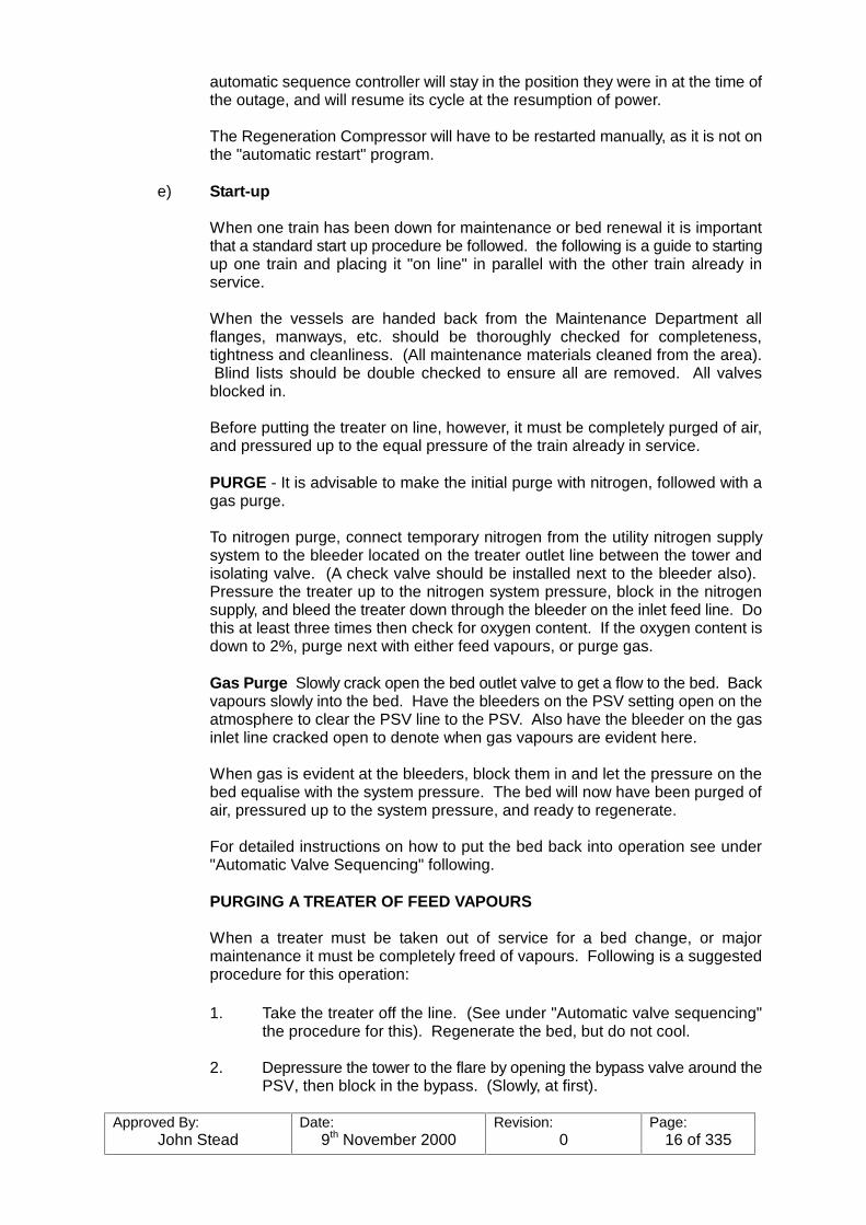
automatic sequence controller will stay in the position they were in at the time ofthe outage, and will resume its cycle at the resumption of power.
The Regeneration Compressor will have to be restarted manually, as it is not onthe "automatic restart" program.
e) Start-up
When one train has been down for maintenance or bed renewal it is importantthat a standard start up procedure be followed. the following is a guide to startingup one train and placing it "on line" in parallel with the other train already inservice.
When the vessels are handed back from the Maintenance Department allflanges, manways, etc. should be thoroughly checked for completeness,tightness and cleanliness. (All maintenance materials cleaned from the area). Blind lists should be double checked to ensure all are removed. All valvesblocked in.
Before putting the treater on line, however, it must be completely purged of air,and pressured up to the equal pressure of the train already in service.
PURGE - It is advisable to make the initial purge with nitrogen, followed with agas purge.
To nitrogen purge, connect temporary nitrogen from the utility nitrogen supplysystem to the bleeder located on the treater outlet line between the tower andisolating valve. (A check valve should be installed next to the bleeder also). Pressure the treater up to the nitrogen system pressure, block in the nitrogensupply, and bleed the treater down through the bleeder on the inlet feed line. Dothis at least three times then check for oxygen content. If the oxygen content isdown to 2%, purge next with either feed vapours, or purge gas.
Gas Purge Slowly crack open the bed outlet valve to get a flow to the bed. Backvapours slowly into the bed. Have the bleeders on the PSV setting open on theatmosphere to clear the PSV line to the PSV. Also have the bleeder on the gasinlet line cracked open to denote when gas vapours are evident here.
When gas is evident at the bleeders, block them in and let the pressure on thebed equalise with the system pressure. The bed will now have been purged ofair, pressured up to the system pressure, and ready to regenerate.
For detailed instructions on how to put the bed back into operation see under"Automatic Valve Sequencing" following.
PURGING A TREATER OF FEED VAPOURS
When a treater must be taken out of service for a bed change, or majormaintenance it must be completely freed of vapours. Following is a suggestedprocedure for this operation:
1. Take the treater off the line. (See under "Automatic valve sequencing"the procedure for this). Regenerate the bed, but do not cool.
2. Depressure the tower to the flare by opening the bypass valve around thePSV, then block in the bypass. (Slowly, at first).
Approved By:John Stead
Date:9th November 2000
Revision:0
Page:17 of 335
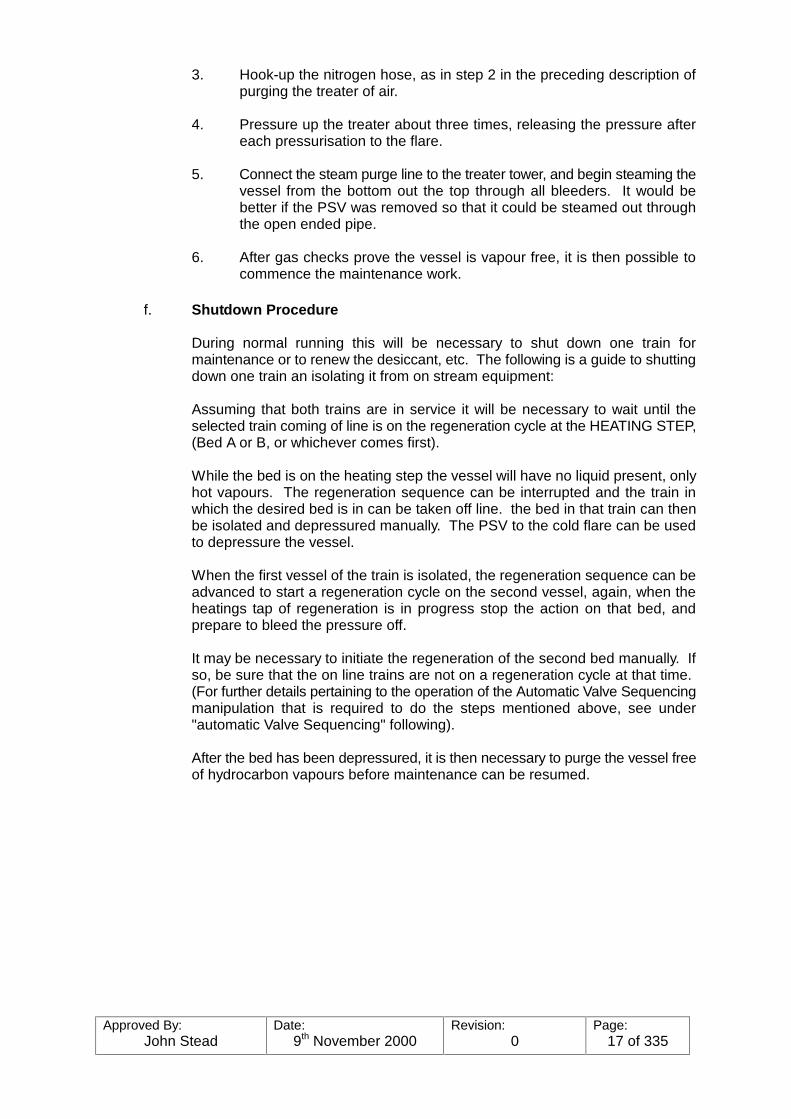
3. Hook-up the nitrogen hose, as in step 2 in the preceding description ofpurging the treater of air.
4. Pressure up the treater about three times, releasing the pressure aftereach pressurisation to the flare.
5. Connect the steam purge line to the treater tower, and begin steaming thevessel from the bottom out the top through all bleeders. It would bebetter if the PSV was removed so that it could be steamed out throughthe open ended pipe.
6. After gas checks prove the vessel is vapour free, it is then possible tocommence the maintenance work.
f. Shutdown Procedure
During normal running this will be necessary to shut down one train formaintenance or to renew the desiccant, etc. The following is a guide to shuttingdown one train an isolating it from on stream equipment:
Assuming that both trains are in service it will be necessary to wait until theselected train coming of line is on the regeneration cycle at the HEATING STEP,(Bed A or B, or whichever comes first).
While the bed is on the heating step the vessel will have no liquid present, onlyhot vapours. The regeneration sequence can be interrupted and the train inwhich the desired bed is in can be taken off line. the bed in that train can thenbe isolated and depressured manually. The PSV to the cold flare can be usedto depressure the vessel.
When the first vessel of the train is isolated, the regeneration sequence can beadvanced to start a regeneration cycle on the second vessel, again, when theheatings tap of regeneration is in progress stop the action on that bed, andprepare to bleed the pressure off.
It may be necessary to initiate the regeneration of the second bed manually. Ifso, be sure that the on line trains are not on a regeneration cycle at that time. (For further details pertaining to the operation of the Automatic Valve Sequencingmanipulation that is required to do the steps mentioned above, see under"automatic Valve Sequencing" following).
After the bed has been depressured, it is then necessary to purge the vessel freeof hydrocarbon vapours before maintenance can be resumed.

Approved By:John Stead
Date:9th November 2000
Revision:0
Page:18 of 335
g. Sequence Controller
Sequence Controller for De-ethaniser Vapour Feed Dehydrators - CabinetUC 51020
Introduction
The de-ethaniser vapour feed dehydrator system is intended to reduce themoisture content of the de-ethaniser vapour feed to prevent the hydrates freezingat the low working temperature of the de-ethaniser condenser.
It comprises four vessels 53-D-14, 53-D-15, 53-D-16, and 53-D-17 which arereferred to as ’bed 1’, ’bed 2’, ’bed 3’ and ’bed 4’ in these instructions. The bedsare arranged in two trains, beds 1 and 2 forming train 1 and beds 3 and 4 formingtrain 2. (Refer to logic diagram number 5206 drawing number 7809.552J81.246).
The sequence controller (UC 51020) is designed to switch the beds automaticallythrough their drying and regeneration sequences. At any one time a bed can be
a) Drying with product inlet and outlet valves open and regeneration valvesclosed.
b) Hot regenerating with product inlet and outlet valves closed andregeneration valves open and the regeneration gas being heated.
c) Cooling with product inlet and outlet valves closed and regenerationvalves open but the regeneration gas by-passing the heater.
d) Idling with the product outlet valve open product inlet valve andregeneration valves closed. (Vessel is pressurised).
The bed may also be taken out of service with all product and regenerationvalves closed. the process requires that at any one time one bed is drying, theremaining beds will be idling or regenerating. Only one bed may be regeneratedat a time.
The regeneration of a bed will immediately follow its drying period. The operatingsequence is drying, regeneration, cooling, idling, drying, regeneration, etc. (Seelogic drawing number 5207 drawing number 7809.55J811.247). Regenerationis achieved by compressing, heating and recycling a proportion of the gas fromthe bed on drying. Cooling is a continuation of this process without heating.
The drying time for each bed is adjustable by present controls between 16 and32 hours whilst the regenerating time is fixed at 8 hours (4 hours hotregeneration and 4 hours cooling). The idling time is dependant on the dryingtime and is automatically adjusted.
Provision is made for the removal of either train from service whilst the automaticsequence remains in operation on the other train.
In this situation the remaining beds will continue with drying the regenerationperiods unchanged but the idling time will be reduced automatically.

Approved By:John Stead
Date:9th November 2000
Revision:0
Page:19 of 335
The cabinet housing the sequence controller is located behind the control roompanel. (See figs, 2.14 to 2.16 inclusive). An operator control unit is mountedremotely in the control panel. (See figs. 2-17). In the automatic mode, thecontroller maintains the correct sequence of operation by opening and closingthe product, regeneration gas and steam valves and stopping and starting theregeneration gas duty compressor.
The unit monitors the position of all valves to ensure that each step of thesequence is done correctly. The status of each valve (with the exception ofsteam and regeneration gas valves for heating and cooling) is displayedcontinuously on the graphic panel in the control room by means of semaphoreindicators.
Any discrepancy between the actual valve position and that required for correctoperation will suspend the sequence and initiate an alarm. The state of eachbed, e.g. ’drying’ ’cooling’ etc. is also indicated on the graphic panel. Thesequence of operation under normal conditions id given later in this introduction. The operator control unit permits the operator to change the operation fromautomatic to manual, open and close any valve and to remove a train fromservice as follows:-
With the ’manual’ button depressed
a) Any valve can be opened or closed by selecting the valve number on thethumbwheel switch an pressing the ’open’ or ’close’ button as appropriate.The valve position will be indicated on the graphic panel
b) The duty compressor can be started or stopped.
c) The temperature control valves on the regeneration gas heater can beclosed or controlled by the output of the temperature controller bypressing the appropriate button.
On start up it is necessary to present and dehydrator control valves in to one offour operational patterns whilst the unit is in manual control prior to switching to’automatic’. These operational patterns are shown on fig, 2.1.
If it is required to remove a train from service the right hand selector switch mustindicate that train and the ’out’ button pressed. the effects of removing a trainfrom service are shown in figs. 2.4 to 2.11 at various times within the sequence. When removed from service all valves associated with the out of service trainwill be closed. They can be operated locally without affecting the Auto sequence.
A train can be returned to service by pressing the ’on’ button at any time. Thebeds will automatically re-enter the sequence but only at their correctly appointedtime. (See fig. 2.12). This is because the position of each bed within thesequence relative to the other beds is always the same.
If a valve is operated locally whilst the sequence controller is in the ’Auto’ positionthe sequence will automatically suspend and an alarm will be initiated.
Approved By:John Stead
Date:9th November 2000
Revision:0
Page:20 of 335
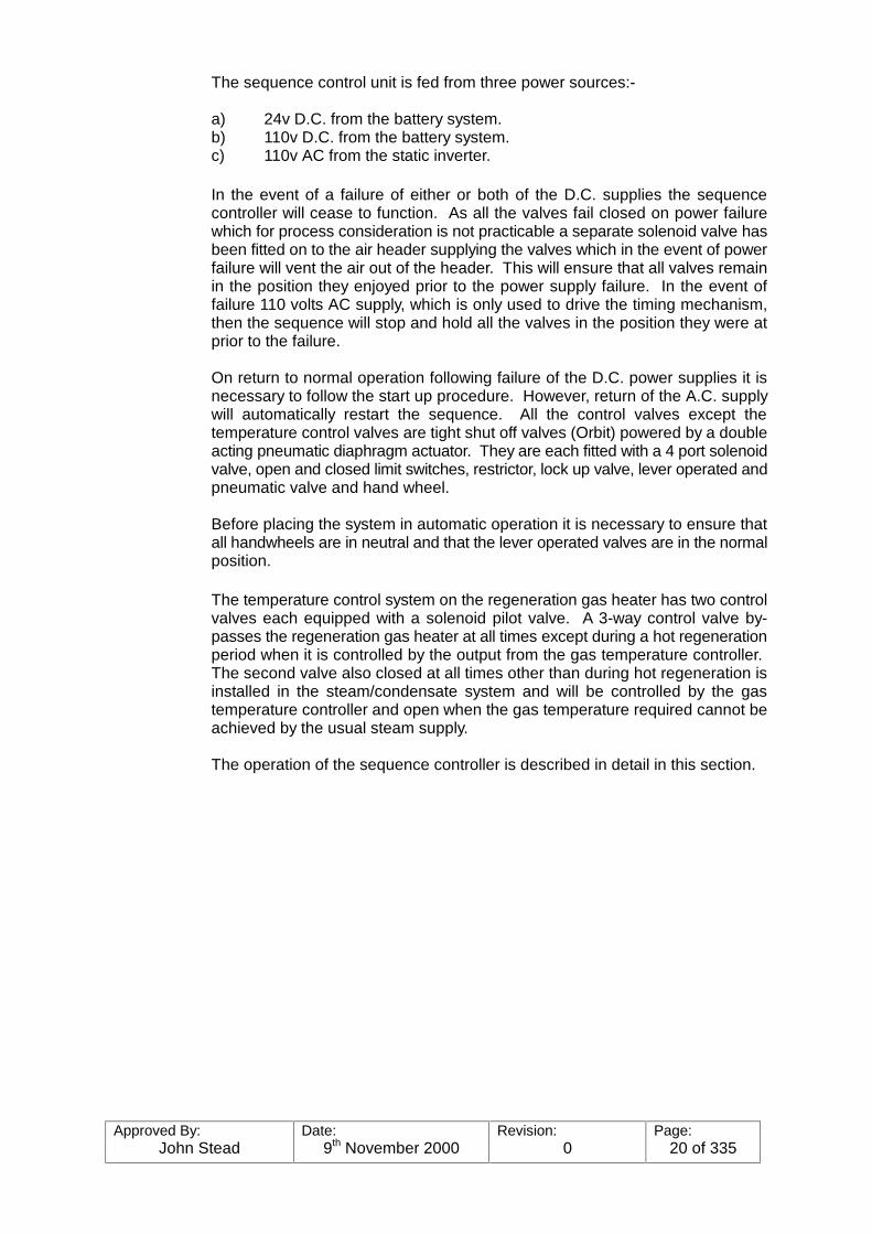
The sequence control unit is fed from three power sources:-
a) 24v D.C. from the battery system.b) 110v D.C. from the battery system.c) 110v AC from the static inverter.
In the event of a failure of either or both of the D.C. supplies the sequencecontroller will cease to function. As all the valves fail closed on power failurewhich for process consideration is not practicable a separate solenoid valve hasbeen fitted on to the air header supplying the valves which in the event of powerfailure will vent the air out of the header. This will ensure that all valves remainin the position they enjoyed prior to the power supply failure. In the event offailure 110 volts AC supply, which is only used to drive the timing mechanism,then the sequence will stop and hold all the valves in the position they were atprior to the failure.
On return to normal operation following failure of the D.C. power supplies it isnecessary to follow the start up procedure. However, return of the A.C. supplywill automatically restart the sequence. All the control valves except thetemperature control valves are tight shut off valves (Orbit) powered by a doubleacting pneumatic diaphragm actuator. They are each fitted with a 4 port solenoidvalve, open and closed limit switches, restrictor, lock up valve, lever operated andpneumatic valve and hand wheel.
Before placing the system in automatic operation it is necessary to ensure thatall handwheels are in neutral and that the lever operated valves are in the normalposition.
The temperature control system on the regeneration gas heater has two controlvalves each equipped with a solenoid pilot valve. A 3-way control valve by-passes the regeneration gas heater at all times except during a hot regenerationperiod when it is controlled by the output from the gas temperature controller. The second valve also closed at all times other than during hot regeneration isinstalled in the steam/condensate system and will be controlled by the gastemperature controller and open when the gas temperature required cannot beachieved by the usual steam supply.
The operation of the sequence controller is described in detail in this section.

Approved By:John Stead
Date:9th November 2000
Revision:0
Page:21 of 335
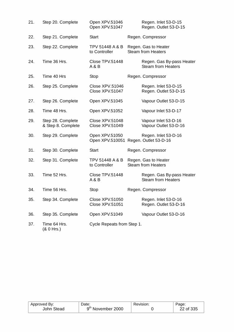
DE-ETHANISER VAPOUR FEED DEHYDRATORNORMAL OPERATING SEQUENCE
1. Time 0 Hrs. Open XPV.51040 Vapour Inlet 53-D-14(264 hours)
2. Step 1. Complete Close XPV.51052 Vapour Inlet 53-D-17& Step 18 Complete Close XPV.51053 Vapour Outlet 53-D-17
3. Step 2. Complete Open XPV.51054 Regen. Inlet 53-D-17Open XPV.51055 Regen. Outlet 53-D-17
4. Step 3. Complete Start Regen. Compressor
5. Step 4. Complete TPV 51448 A & B Regen. Gas to Heaterto Controller Steam from Heaters
6. Time 4 Hrs. Close TPV.51448 Regen. Gas by-Passes HeaterA & B Steam from Heaters
7. Time 8 Hrs. Stop Regen. Compressor
8. Step 7. Complete Close XPV.51054 Regen. Inlet 53-D-17Close XPV.51055 Regen. Outlet 53-D-17
9. Step 8. Complete Open XPV.51053 Vapour Outlet 53-D-17
10. Time 16 Hrs. Open XPV.51044 Vapour Inlet 53-D-15
11. Step 10. Complete Close XPV.51040 Vapour Inlet 53-D-14& Step 27 Complete Close XPV.51041 Vapour Outlet 53-D-14
12. Step 11. Complete Open XPV.51042 Regen. Inlet 53-D-14Open XPV.51043 Regen. Outlet 53-D-14
13. Step 12. Complete Start Regen. Compressor
14. Step 13. Complete TPV 51448 A & B Regen. Gas to Heaterto Controller Steam from Heaters
15. Time 20 Hrs. Close TPV.51448 Regen. Gas By-pass HeaterA & B Steam from Heaters
16. Time 24 Hrs. Stop Regen. Compressor
17. Step 16. Complete Close XPV.51042 Regen. Inlet 53-D-14Close XPV.51043 Regen. Outlet 53-D-14
18. Step 17. Complete Open XPV.51041 Vapour Outlet 53-D-14
19. Time 32 Hrs. Open XPV.51048 Vapour Inlet 53-D-16
20. Step 19. Complete Close XPV.51044 Vapour Inlet 53-D-15& Step 36. Complete Close XPV.51045 Vapour Outlet 53-D-15
Approved By:John Stead
Date:9th November 2000
Revision:0
Page:22 of 335
21. Step 20. Complete Open XPV.51046 Regen. Inlet 53-D-15Open XPV.51047 Regen. Outlet 53-D-15
22. Step 21. Complete Start Regen. Compressor
23. Step 22. Complete TPV 51448 A & B Regen. Gas to Heaterto Controller Steam from Heaters
24. Time 36 Hrs. Close TPV.51448 Regen. Gas By-pass HeaterA & B Steam from Heaters
25. Time 40 Hrs Stop Regen. Compressor
26. Step 25. Complete Close XPV.51046 Regen. Inlet 53-D-15Close XPV.51047 Regen. Outlet 53-D-15
27. Step 26. Complete Open XPV.51045 Vapour Outlet 53-D-15
28. Time 48 Hrs. Open XPV.51052 Vapour Inlet 53-D-17
29. Step 28. Complete Close XPV.51048 Vapour Inlet 53-D-16& Step 8. Complete Close XPV.51049 Vapour Outlet 53-D-16
30. Step 29. Complete Open XPV.51050 Regen. Inlet 53-D-16Open XPV.510051 Regen. Outlet 53-D-16
31. Step 30. Complete Start Regen. Compressor
32. Step 31. Complete TPV 51448 A & B Regen. Gas to Heaterto Controller Steam from Heaters
33. Time 52 Hrs. Close TPV.51448 Regen. Gas By-pass HeaterA & B Steam from Heaters
34. Time 56 Hrs. Stop Regen. Compressor
35. Step 34. Complete Close XPV.51050 Regen. Inlet 53-D-16Close XPV.51051 Regen. Outlet 53-D-16
36. Step 35. Complete Open XPV.51049 Vapour Outlet 53-D-16
37. Time 64 Hrs. Cycle Repeats from Step 1.(& 0 Hrs.)
Approved By:John Stead
Date:9th November 2000
Revision:0
Page:23 of 335
2.1 General Description
The Sequence Controller consists of solid state circuit modules mounted on standardcards in racks together within a single bay steel enclosure UC 51020, and a separatecontrol sub-panel.
The racks are mounted on a swing frame which allows access to the rear of the cardsockets and to the rear of the cabinet.
Connection to plant equipment is via screw-clamp terminals situated within the rear ofthe enclosure, entry to which is by top and bottom entry gland plates.
The logic circuits are connected to the screw-clamp terminals via plugs and socketsadjacent to the terminals. This enables the logic to be disconnected from the plantswitches and solenoids, and connected to the simulator for testing and fault-finding.
The enclosure may be electrically isolated by means of a push-button on the front of theswing frame.
An operational description is given briefly showing the action when beds are taken outof and returned to service.
2.2 Operational Description - Cabinet UC 51020
2.2.1 Start Up and Normal Operation
Before applying the supply to the cabinet by pressing the START button on theswing frame, the AUTO/MANUAL switch on the sub-panel should be set toMANUAL. If this is not done all action will be inhibited when the START BUTTONis operated.
The start button may now be pressed, but at this point in time all plant solenoidswill remain de-energised. It is now possible to operate the plant manually.
Valves TPV 51448A & B may be opened or closed by operating the appropriatepush-buttons on the sub-panel. Similarly the compressor may be started andstopped.
Valves XPV 51040 to XPV 51055 inclusive may be operated by selecting the lasttwo digits of the valve number on the sub-panel thumbwheel switches and thenoperating the OPEN or CLOSE push-button tot he left of the thumbwheelswitches. The valve selected will remain in the state chosen even though othervalves are now selected
For example, if it was required to open XPV 51045, the thumbwheel switcheswould be set to 45 and the OPEN push-button would be operated. Valve XPV51045 would then open due to its solenoid being operated and would remainopen even though XPV 51048, say, was then selected.
If it is required to operate the plant in AUTO, it is first necessary to set all valvesmanually to one of four points in a normal sequence. These four points areshown in fig. 2-1. In fig. 2-1 the two trains (or four beds) are shown as drying,idling or regeneration. During drying the VAPOUR INLET and VAPOUR OUTLETvalves are open and the compressor is running. For the first half of theregeneration period the HEATER INLET & STEAM valves (TPV 51448A & B) areon control by TIC 51448.
Approved By:John Stead
Date:9th November 2000
Revision:0
Page:24 of 335
The valves are designated as follows (XPV preceeds all valve numbers):-
Duty Column Column Column Column
519-950-14 519-950-15 519-950-16 519-950-17Vapour Inlet 51040 51044 51048 51052Vapour Outlet 51041 51045 51049 51053Regen. Inlet 51042 51046 51050 51054Regen. Outlet 51043 51047 51051 51055
Having set the valves to one of the four points of entry, the rotary switch on thesub-panel headed BED to START ON REGENERATION AT START OF AUTOSEQUENCE should be set to the corresponding position.
The AUTO push-button may now be operated and the plant will continue tooperate automatically, according to the sequence shown in fig. 2-1, and themanual controls will be rendered ineffective.
Referring to fig. 2-1, it may be noted that a sequence can be broken down intoequal sections (in this case of 8 hours each). This the drying period occupies 2sections, regeneration one section and idling 5 sections.
During commissioning or other shut-down times the length of the sections maybe set between 8 hours and 16 hours in 30 minute increments, by setting the totaldrying time, which is effected by switches within the main enclosures.
The thumbwheels should only be varied between 16 (which gives 16 hours dryingtime) and 32 (which gives 32 hours drying time).
Fig. 2-2 shows a sequence with 12 hour sections (that is 24 hours drying time)and fig. 2-3 shows a sequence with 16 hour sections.
In these figures it will be noted that drying still occupies two sections butregeneration time remains constant at 8 hours as in fig. 2-1. The remainder ofthe section following drying is then taken up as idling.
2.2.2 Taking a Train Out of Service
To take a train out of service the sub-panel rotary switch designated TRAIN TOBE TAKEN OUT OF SERVICE is set to the appropriate position. The push-button to the right of the rotary switch is then operated.
The sequence immediately following the action of taking a train out will dependon the point at which the train is taken out. Figures 2-4 to 2-11 show the resultingsequences when train 1 is taken out during each of its sections of operation. Forthe purposes of discussion the section immediately following drying will bereferred to as regeneration even though the first 8 hours only are taken up withregeneration.
Approved By:John Stead
Date:9th November 2000
Revision:0
Page:25 of 335
2.3 Returning a Train to Service
This may be accomplished by setting the rotary switch of para. 2.2.2. to the appropriateposition and operating the push-button.
The push-button may be operated at any time, however the train will not be returned toservice until the points indicated in fig. 2-12.
Approved By:John Stead
Date:9th November 2000
Revision:0
Page:26 of 335
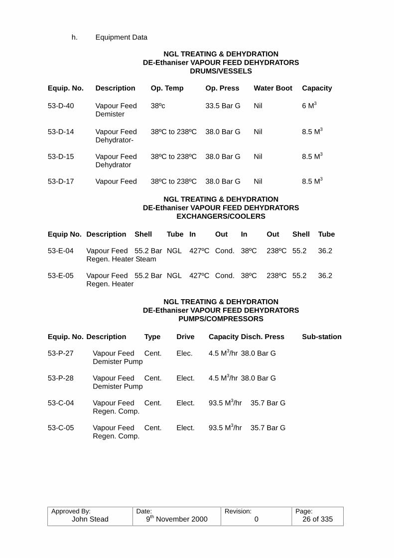
h. Equipment Data
NGL TREATING & DEHYDRATIONDE-Ethaniser VAPOUR FEED DEHYDRATORS
DRUMS/VESSELS
Equip. No. Description Op. Temp Op. Press Water Boot Capacity
53-D-40 Vapour Feed 38ºc 33.5 Bar G Nil 6 M3
Demister
53-D-14 Vapour Feed 38ºC to 238ºC 38.0 Bar G Nil 8.5 M3
Dehydrator-
53-D-15 Vapour Feed 38ºC to 238ºC 38.0 Bar G Nil 8.5 M3
Dehydrator
53-D-17 Vapour Feed 38ºC to 238ºC 38.0 Bar G Nil 8.5 M3
NGL TREATING & DEHYDRATIONDE-Ethaniser VAPOUR FEED DEHYDRATORS
EXCHANGERS/COOLERS
Equip No. Description Shell Tube In Out In Out Shell Tube
53-E-04 Vapour Feed 55.2 Bar NGL 427ºC Cond. 38ºC 238ºC 55.2 36.2Regen. Heater Steam
53-E-05 Vapour Feed 55.2 Bar NGL 427ºC Cond. 38ºC 238ºC 55.2 36.2Regen. Heater
NGL TREATING & DEHYDRATIONDE-Ethaniser VAPOUR FEED DEHYDRATORS
PUMPS/COMPRESSORS
Equip. No. Description Type Drive Capacity Disch. Press Sub-station
53-P-27 Vapour Feed Cent. Elec. 4.5 M3/hr 38.0 Bar GDemister Pump
53-P-28 Vapour Feed Cent. Elect. 4.5 M3/hr 38.0 Bar GDemister Pump
53-C-04 Vapour Feed Cent. Elect. 93.5 M3/hr 35.7 Bar GRegen. Comp.
53-C-05 Vapour Feed Cent. Elect. 93.5 M3/hr 35.7 Bar GRegen. Comp.
Approved By:John Stead
Date:9th November 2000
Revision:0
Page:27 of 335
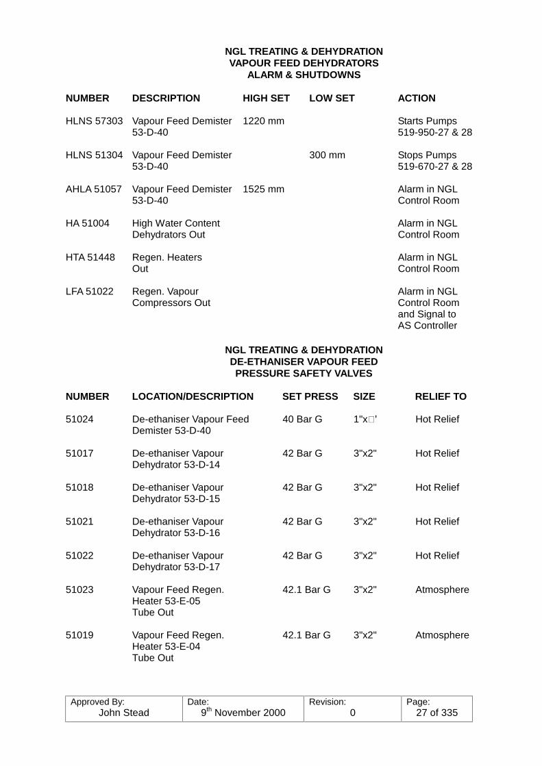
NGL TREATING & DEHYDRATIONVAPOUR FEED DEHYDRATORS
ALARM & SHUTDOWNS
NUMBER DESCRIPTION HIGH SET LOW SET ACTION
HLNS 57303 Vapour Feed Demister 1220 mm Starts Pumps53-D-40 519-950-27 & 28
HLNS 51304 Vapour Feed Demister 300 mm Stops Pumps53-D-40 519-670-27 & 28
AHLA 51057 Vapour Feed Demister 1525 mm Alarm in NGL53-D-40 Control Room
HA 51004 High Water Content Alarm in NGLDehydrators Out Control Room
HTA 51448 Regen. Heaters Alarm in NGLOut Control Room
LFA 51022 Regen. Vapour Alarm in NGLCompressors Out Control Room
and Signal toAS Controller
NGL TREATING & DEHYDRATIONDE-ETHANISER VAPOUR FEEDPRESSURE SAFETY VALVES
NUMBER LOCATION/DESCRIPTION SET PRESS SIZE RELIEF TO
51024 De-ethaniser Vapour Feed 40 Bar G 1"x� Hot ReliefDemister 53-D-40
51017 De-ethaniser Vapour 42 Bar G 3"x2" Hot ReliefDehydrator 53-D-14
51018 De-ethaniser Vapour 42 Bar G 3"x2" Hot ReliefDehydrator 53-D-15
51021 De-ethaniser Vapour 42 Bar G 3"x2" Hot ReliefDehydrator 53-D-16
51022 De-ethaniser Vapour 42 Bar G 3"x2" Hot ReliefDehydrator 53-D-17
51023 Vapour Feed Regen. 42.1 Bar G 3"x2" AtmosphereHeater 53-E-05Tube Out
51019 Vapour Feed Regen. 42.1 Bar G 3"x2" AtmosphereHeater 53-E-04Tube Out
Approved By:John Stead
Date:9th November 2000
Revision:0
Page:28 of 335
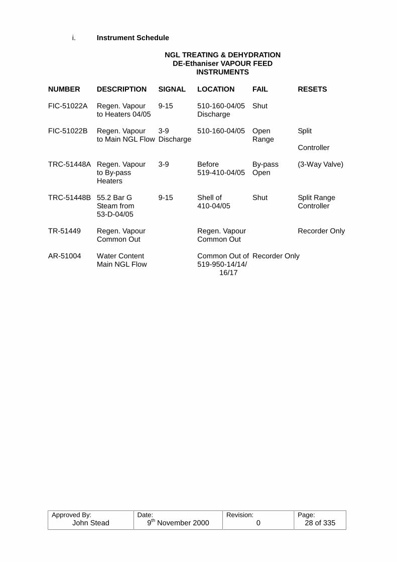
i. Instrument Schedule
NGL TREATING & DEHYDRATIONDE-Ethaniser VAPOUR FEED
INSTRUMENTS
NUMBER DESCRIPTION SIGNAL LOCATION FAIL RESETS
FIC-51022A Regen. Vapour 9-15 510-160-04/05 Shutto Heaters 04/05 Discharge
FIC-51022B Regen. Vapour 3-9 510-160-04/05 Open Splitto Main NGL Flow Discharge Range
Controller
TRC-51448A Regen. Vapour 3-9 Before By-pass (3-Way Valve)to By-pass 519-410-04/05 OpenHeaters
TRC-51448B 55.2 Bar G 9-15 Shell of Shut Split RangeSteam from 410-04/05 Controller53-D-04/05
TR-51449 Regen. Vapour Regen. Vapour Recorder OnlyCommon Out Common Out
AR-51004 Water Content Common Out of Recorder OnlyMain NGL Flow 519-950-14/14/
16/17
Approved By:John Stead
Date:9th November 2000
Revision:0
Page:29 of 335
3. NGL TREATING & DEHYDRATION
De-ethaniser Liquid Feed Dehydrators
a) Introduction
The purpose of the de-ethaniser liquid feed dehydrators is to remove water fromthe stabiliser overhead liquid product to less than 10ppm before being used asa feed stock for the de-ethaniser columns. This is necessary to prevent theformation of "hydrates" which will cause plugging of the tubes in the de-ethaniserreflux condenser.
Water removal is accomplished by pumping the liquid de-ethaniser feed from thede-ethaniser feed surge tank through a set of towers containing fixed beds ofmolecular sieve desiccant which removes the water from the hydrocarbon byadsorption. The product is then dry, and suitable for de-ethaniser feed. Whena dryer bed becomes saturated with water to a pre-determined point it is removedfrom service, regenerated, cooled, and put on a stand-by condition while anotherdrier is being used in its place.
This section includes the following equipment:-
De-ethaniser Liquid Feed Dehydrators - 53-E-05/06/07/08/09/10De-ethaniser Liquid Feed Filters - 53-FF-01/02/03De-ethaniser Liquid Feed Regen. Vaporisers - 53-E-31-32-33De-ethaniser Liquid Feed Regen. Superheaters - 53-E-34-35-36De-ethaniser Liquid Feed Regen. Pumps - 53-P-04/05/06De-ethaniser Liquid Feed Regen. Separators - 53-D-950-01/02
b) Flow Description
The NGL will be pumped from the stabiliser accumulators at a dischargepressure of 38.5 Bar G, to the de-ethaniser surge tanks,53-D-03/04. It is then pumped via the de-ethaniser feed pumps,53-00-P-01/02/03, at a discharge pressure of 30 Bar G and 26ºC into the dryingequipment. The NGL is just below boiling point, and if it were fed by gravity tothe dehydrator beds, the pressure drop across the bed could cause "FLASHING"which would damage the desiccant. The feed pumps are situated before thedehydrators to prevent this. A high discharge pressure or low surge tank levelwill stop the pumps automatically. the differential pressure between the suctionand discharge of the pumps is controlled by DPIC-51060, with a re-cycle back tothe surge tank, which will protect the pumps and prevent over heating due to highdischarge pressure (during dehydrator changeover). The discharged liquidenters a common 8" header to supply the dehydrators.
There are six dehydrators, and for the purpose of dehydration, are paired off intwo's. Each pair will be termed a "TRAIN", i.e. two vessels in each train. One ofeach train will be in operation in parallel, while the other three will be in differentstages of regeneration. Normal flow during the drying step will be from TOP toBOTTOM, and the normal cycles will be as follows:-
DRYING (on stream) 60 hoursHEATING 8 hoursCOOLING 4 hoursSTAND-BY 48 hours
Approved By:John Stead
Date:9th November 2000
Revision:0
Page:30 of 335
In the event of one train being "off stream" for maintenance etc., two trains canhandle full flow rate. The regeneration sequence control timer will have to bechanged to a one off, one on basis.
Each dehydrator is a vertical mounted vessel, 15’ x 6’6", and filled with amolecular sieve desiccant. This desiccant is supported by a layer of ¼" aluminaballs, and that supported by a layer of ½" alumina balls. This layer is supportedby a stainless steel screen. The NGL flows down through the bed and anymoisture is adsorbed in the desiccant, leaving the NGL "DRY".
Moisture analysers are installed in the product lines from each train, and willalarm in the NGL Control Room if the water content rises above normal, or if theanalyser fails.
The flow through the dehydrators should be adjusted manually with the controlvalves provided, to ensure each vessel has an equal load. Local flow indicatorsat the exit of each train are supplied to monitor the flow.
A minimum flow rate of 50.7 M3/hr is recommended through each bed to preventchannelling.
Dried NGL leaves the bottom of the dehydrators and flows through the liquid feedfilters. These filters will remove any "FINES" which may be carried through fromthe dehydrators. There is one filter on the exit from each train, which is designedto remove 95% of 50 micron particles from the NGL. They are FRAM, basketstrainer type filters and maximum differential is 25 psi, but should be cleanedbefore this pressure is reached. NGL flow then carries on through the flowindicators, and hand operated flow control valves, HC 51001/2/3 (to equalise theflow), and joins a 10" common header, then carrying on to the de-ethanisertowers, S-T-05/06, for further processing. At this point the pressure is 30 Bar G,at 26ºC.
The liquid feed flow rate is controlled by the feed surge tank level control via theadvanced control scheme.
Flows, pressures and temperatures will be monitored in the Control Building.
c. Regeneration
The various cycles for drying and regeneration will be controlled. Differentcombinations of heaters and pumps (all interchangeable) can also be used.
A side stream of dried NGL is taken from the common outlet header of thedehydrators and supplies suction to the regeneration pumps, 53-P-04/05/06. They are electric driven pumps, one of which will be on stand-by duty, while theother two are in operation. They will discharge the NGL at 38.6 Bar and 38ºC,into a 3" line. Via this line the flow can be directed through the heaters for theheating step, or direct to the dehydrators for the cooling step. the regenerationflow rate will be controlled at 15.89 M3/Hr. by C-51016/7/8, for both heating andcooling steps.
Approved By:John Stead
Date:9th November 2000
Revision:0
Page:31 of 335
Heating Step
The regen. NGL flow will be routed from the common 3" discharge line, throughthe flow controller, to a 3" line which will go direct to the tube side of the regen.liquid vapouriser 53-E-31/32/33. The regen. NGL temperature will be raised with3.5 Bar steam. flowing through the shell side. The flow will then exit from the topof the vapouriser and enter a 3-way control valve, TPV-51442/6A. This controlvalve will route the flow either through the superheaters (53-E-35,36) or by-passing the superheater, depending on the temperature of the common outlet.The hot NGL will then flow direct to the TOP of the dehydrator on regeneration.The temperature will be controlled at 238ºC with TC-51442/6 "A" and "B", whichis a split range controller.
The "A" valve, which is the 3-way control valve on the regen. flow before thesuperheaters, will control the relevant amount of NGL flowing through or by-passing the superheater. When the by-pass port of the "A" valve is fully closed(all flow through the superheater), the "B" valve, which is controlling a flow of55.2 Bar steam through the shell side of the superheater to the 5.2 Bar steamheader, can open, allowing more steam to flow through the superheater,therefore raising the temperature of the regen. NGL quicker. Once thetemperature is raised to the set-point, the "B" valve will close and the "A" valvewill then control the temperature by allowing more or less flow through thesuperheater.
The hot regen. NGL enters the TOP of the dehydrators and flows DOWN throughthe desiccant, picking up the moisture from the bed.
The wet regen. NGL exits from the bottom of the dehydrator, and is routed to oneof the two regeneration separators, 53-D-01/02.
The regeneration separators are designed so that one will be in operation andone on stand-by. Both are complete with ancillary equipment, i.e level glasses,alarms, PSV's, vents and drains, and filled with PALL RINGS, to obtain maximumseparation of liquid from vapour. The NGL liquid from the bottom of the separatorand the NGL vapour from the top, are returned to the inlets of the liquid andvapour stabilisers overhead compressor after coolers, 510-410-06, joining themain vapour and liquid flows to the de-ethaniser feed surge tank. Any water willbe collected and drained from the water boots in the surge tank.
Cooling Step
After the heating step is completed, the regen. NGL flow will be re-routed afterthe flow controller, FC-51015/7/8, to the BOTTOM of the dehydrator, and will flowUP through the bed, cooling back to the operating temperature of 26ºC. Thecooling NGL will exit from the top of the dehydrators and via the regenerationlines, be routed to the regeneration separators, following the same flow fromthere as the heating step.
The cooling flow rate (15.89 M3/hr) is low enough that there is no danger offluidising the bed when all of the liquid vapourises, as it will during the first partof the cooling step.
Approved By:John Stead
Date:9th November 2000
Revision:0
Page:32 of 335
a) De-ethaniser Liquid Feed Dehydrators
Normal Start-up Procedure (one train)
When one train has been shutdown for maintenance or bed renewal, itis important that a standard start-up procedure be followed. Thefollowing is a guide to starting up one train and placing it ’ON LINE’ inparallel with the two trains already in service.
When the vessels are handed back from the Maintenance Department,all flanges, manways, etc. should be thoroughly checked forcompleteness, tightness, correct gaskets (size and type) and cleanliness(all maintenance materials cleared from the area). Blind list should bedouble checked to ensure all blinds removed.
All valves in the system should be checked and shut to ensure purgingis done in a controlled, methodical manner.
The following can now be carried out on a step by step basis:
1. Open the PSV vent valve on top of each vessel fully to allow freeflow of air to atmosphere.
2. Commence N2 purge, with at least 3 changes.
Purging should continue in this manner until the oxygen contentis less than 2% of vessel volume before requesting Labs tosample for oxygen.
3. When oxygen content is 2% commission PSV and vent valve,shut the PSV. (The PSV by-pass will be required for removing N2
so do not fit car seals to the by-pass at this point). Whilepressure is rising, carry out a complete inspection of all flanges,etc. for leakage.
4. When the vessels have reached operating pressure, carry out hotand cold regens before returning the bed to service.
b) De-ethaniser Liquid Feed Dehydrators
Shutdown Procedure (one train)
During normal running it will be necessary to shutdown one train formaintenance or to renew the desiccant etc. The following is a guide toshutting down one train and isolating from on stream equipment:
Assuming that all three trains are in service, it will be necessary to waituntil the selected train coming off line is on a regeneration cycle at theHEATING STEP.
While the bed is on the heating step, the vessel will have no liquidpresent (only hot vapour will be passing through).
Approved By:John Stead
Date:9th November 2000
Revision:0
Page:33 of 335
The PSV by-passes to cold relief header can be used to depressure thevessels.
NOTE: When carrying out heating step ensure beds are regened to ’FirstPlateau’ only i.e. vapourised and not superheated. In this way, cold ventpipework will not be overheated when the beds are depressured.
It may be necessary to initiate the regeneration on the second vessel and carry it out manually. If so, be sure that the on line trains are not ona regeneration cycle at that time.
Power Failure
In the event of a power outage all switching valves associated with theautomatic valve sequence control will remain in the position they wee inat the time of the outage.
Instrument Failure
In the event of loss of the instrument air all switching valves controlled bythe DCS will remain in the position they were in at the time of the failure.
It will be necessary to shutdown the de-ethaniser feed pumps, and theregeneration gas pumps as soon as possible, as the feed motor valvesfor the De-ethaniser will fail closed, and the regeneration gas controlvalves will fail open.
With three compressors, however, it is unlikely that an instrument airfailure will occur, but is not impossible. Closed, the regeneration valvesopen and the regeneration gas being heated.
In the event of a failure of either or both of the D.C. supplies thesequence controller will cease to function. As all the valves fail closed onpower failure which for process considerations is not practicable aseparate solenoid valve has been fitted on to the air header supplying thevalves which in the event of power failure will vent the air out of theheader. This will ensure that all valves remain in the position theyenjoyed prior to the power supply failure.
All the control valves except the temperature control valves are tight shutoff valves (orbit) powered by a double acting pneumatic diaphragmactuator. They are each fitted with a 4-port solenoid valve, open andclosed limit switches, restrictor, lock up valve, level operated pneumaticvalve and handwheel. Before placing the system in automatic operationit is necessary to ensure that all handwheels are in neutral and that thelevel operated valves are in the normal operation.
The temperature control system on the regeneration gas heater has twocontrol valves. Only the steam valve is operated by the sequencecontroller via a solenoid valve.
Approved By:John Stead
Date:9th November 2000
Revision:0
Page:34 of 335
A 3-way control valve is controlled by the output from the gas temperaturecontroller. the steam valve is closed at all times other than during hotregeneration and is installed in the steam/condensate system. It will becontrolled by the gas temperature controller during hot regeneration andwill open when the gas temperature required cannot be achieved by theusual steam supply.

Approved By:John Stead
Date:9th November 2000
Revision:0
Page:35 of 335
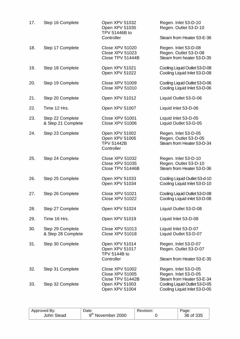
DE-Ethaniser LIQUID FEED DEHYDRATORS
NORMAL OPERATING SEQUENCE
1. Time 0 Hrs. Open XPV 51001 Liquid Inlet 53-D-05(& 60 Hrs.)
2. Step 1 Complete Close XPV 51007 Liquid Inlet 53-D-06& Step 41 Complete Close XPV 51012 Liquid Outlet 53-D-06
3. Step 2 Complete Open XPV 51008 Regen Inlet 53-D-06Open XPV 51011 Regen. Outlet 53-D-06TPV 51442B toController Steam from Heater 53-E-34
4. Step 3 Complete Close XPV 51026 Regen. Inlet 53-D-09Close XPV 51029 Regen. Outlet 53-D-09Close TPV 51446B Steam from Heater 53-E-36
5. Step 4 Complete Open XPV 51027 Cooling Liquid Outlet 53-D-09Open XPV 51028 Cooling Liquid Inlet 53-D-09
6. Step 5 Complete Close XPV 51015 Cooling Liquid Outlet 53-D-07Close XPV 51016 Cooling Liquid Outlet 53-D-
07
7. Step 6 Complete Open XPV 51018 Liquid Outlet 53-D-07
8. Time 4 Hrs. Open XPV 51013 Liquid Inlet 53-D-07
9. Step 8 Complete Close XPV 51019 Liquid Inlet 53-D-08& Step 7 Complete Close XPV 51024 Liquid Outlet 53-D-08
10. Step 9 Complete Open XPV 51020 Regen. Inlet 53-D-08Open XPV 51023 Regen. Outlet 53-D-08TPV 51444B toController Steam from Heater 53-E-35
11. Step 10 Complete Close XPV 51008 Cooling Liquid Outlet 53-D-06Close XPV 51011 Cooling Liquid Inlet 53-D-06Close TPV 51442B Steam from Heater 53-E-34
12. Step 11 Complete Open XPV 51009 Cooling Liquid Outlet 53-D-34Open XPV 51010 Cooling Liquid Inlet 53-D-06
13. Step 12 Complete Close XPV 51027 Cooling Liquid Outlet 53-D-09Close XPV 51028 Cooling Liquid Inlet 53-D-09
14. Step 13 Complete Open XPV 51030 Liquid Outlet 53-D-09
15. Time 8 Hrs. Open XPV 51025 Liquid Inlet 53-D-09
16. Step 15 Complete Close XPV 51031 Liquid Inlet 53-D-10& Step 14 Complete Close XPV 51036 Liquid Outlet 53-D-10
Approved By:John Stead
Date:9th November 2000
Revision:0
Page:36 of 335
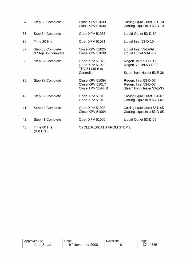
17. Step 16 Complete Open XPV 51032 Regen. Inlet 53-D-10Open XPV 51035 Regen. Outlet 53-D-10TPV 51446B toController Steam from Heater 53-E-36
18. Step 17 Complete Close XPV 51020 Regen. Inlet 53-D-08Close XPV 51023 Regen. Outlet 53-D-08Close TPV 51444B Steam from heater 53-D-35
19. Step 18 Complete Open XPV 51021 Cooling Liquid Outlet 53-D-08Open XPV 51022 Cooling Liquid Inlet 53-D-08
20. Step 19 Complete Close XPV 51009 Cooling Liquid Outlet 53-D-06Close XPV 51010 Cooling Liquid Inlet 53-D-06
21. Step 20 Complete Open XPV 51012 Liquid Outlet 53-D-06
22. Time 12 Hrs. Open XPV 51007 Liquid Inlet 53-D-06
23. Step 22 Complete Close XPV 51001 Liquid Inlet 53-D-05& Step 21 Complete Close XPV 51006 Liquid Outlet 53-D-05
24. Step 23 Complete Open XPV 51002 Regen. Inlet 53-D-05Open XPV 51005 Regen. Outlet 53-D-05TPV 51442B Steam from Heater 53-D-34Controller
25. Step 24 Complete Close XPV 51032 Regen. Inlet 53-D-10Close XPV 51035 Regen. Outlet 53-D-10Close TPV 51446B Steam from Heater 53-D-36
26. Step 25 Complete Open XPV 51033 Cooling Liquid Outlet 53-d-10Open XPV 51034 Cooling Liquid Inlet 53-D-10
27. Step 26 Complete Close XPV 51021 Cooling Liquid Outlet 53-D-08Close XPV 51022 Cooling Liquid inlet 53-D-08
28. Step 27 Complete Open XPV 51024 Liquid Outlet 53-D-08
29. Time 16 Hrs. Open XPV 51019 Liquid Inlet 53-D-08
30. Step 29 Complete Close XPV 51013 Liquid Inlet 53-D-07& Step 28 Complete Close XPV 51018 Liquid Outlet 53-D-07
31. Step 30 Complete Open XPV 51014 Regen. Inlet 53-D-07Open XPV 51017 Regen. Outlet 53-D-07TPV 5144B toController Steam from Heater 53-E-35
32. Step 31 Complete Close XPV 51002 Regen. Inlet 53-D-05Close XPV 51005 Regen. Inlet 53-D-05Close TPV 51442B Steam from Heater 53-E-34
33. Step 32 Complete Open XPV 51003 Cooling Liquid Outlet 53-D-05Open XPV 51004 Cooling Liquid Inlet 53-D-05
Approved By:John Stead
Date:9th November 2000
Revision:0
Page:37 of 335
34. Step 33 Complete Close XPV 51033 Cooling Liquid Outlet 53-D-10Close XPV 51034 Cooling Liquid Inlet 53-D-10
35. Step 34 Complete Open XPV 51036 Liquid Outlet 53-D-10
36. Time 20 Hrs. Open XPV 51031 Liquid Inlet 53-D-10
37. Step 36 Complete Close XPV 51025 Liquid Inlet 53-D-09& Step 35 Complete Close XPV 51030 Liquid Outlet 53-D-09
38. Step 37 Complete Open XPV 51026 Regen. Inlet 53-D-09Open XPV 51029 Regen. Outlet 53-D-09TPV 51446 B toController Steam from Heater 53-E-36
39. Step 38 Complete Close XPV 51054 Regen. Inlet 53-D-07Close XPV 51017 Regen. Inlet 53-D-07Close TPV 51444B Steam from Heater 53-E-35
40. Step 39 Complete Open XPV 51015 Cooling Liquid Outlet 53-D-07Open XPV 51016 Cooling Liquid Inlet 53-D-07
41. Step 40 Complete Open XPV 51003 Cooling Liquid Outlet 53-D-05Close XPV 51004 Cooling Liquid Inlet 53-D-05
42. Step 41 Complete Open XPV 51006 Liquid Outlet 53-D-05
43. Time 60 Hrs. CYCLE REPEATS FROM STEP 1;(& 0 Hrs.)
Approved By:John Stead
Date:9th November 2000
Revision:0
Page:38 of 335
3. SEQUENCE CONTROLLER FOR DE-Ethaniser LIQUID FEED DEHYDRATORSCABINET UC 51021
3.1 General Description
The Sequence Controller consists of solid state circuit modules mounted on standardcards in racks together with relays and other electromechanical devices mounted withinat two-bay steel enclosure UC 51021, and a separate control sub-panel.
The racks are mounted on swing frames which allows access to the rear of the cardsockets and to the rear of the cabinet.
Connection to plant equipment is via screw-clamp terminals situated within the rear ofthe enclosure, entry to which is by top and bottom entry gland plates.
The logic circuits are connected to the screw-clamp terminals via plugs and socketsadjacent to the terminals. This enables the logic to be disconnected from the plantswitches and solenoids, and connected to the simulator.
The enclosure may be electrically isolated by means of a push-button switch on the frontof the right hand swing frame.
The logic circuits have been broken down into blocks to facilitate description.
an operational description is given briefly showing the action when trains are taken outof and returned to service.
3.2 Operational Description - Cabinet UC 51021
3.2.1 Start-up and Normal Operation
Before applying the supply to the cabinet by pressing the START button on theright hand swing frame, the AUTO/MANUAL switch on the sub-panel should beset to MANUAL. If this is not done all action will be inhibited.
The START button may now be pressed, but at this point in time all plantsolenoids will remain de-energised. It is now possible to operate the plantmanually. Valves TPV 51442B, TPV 51444B and TPV 51446B may be openedor closed by operating the appropriate push-buttons on the sub-panel.
Valves XPV 51001 to XPV 51036 inclusive may be operated by selecting the lasttwo digits of the valve number on the sub-panel thumbwheel switches and thenoperating the OPEN or CLOSE push-buttons to the left of the thumbwheelswitches. The valve selected will remain in the state chosen even though othervalves are now selected.
For example, if it was required to open XPV 51006, the thumbwheel switcheswould be set to 06 and the OPEN push-button would be operated. Valve XPV51006 would then open due to its solenoid being operated and would remainopen even though XPV 51013, say, was then selected.
If it is required to operate the plant in AUTO, it is first necessary to set all valvesmanually to one of three points in a normal sequence. These three points areshown in fig. 3.1.

Approved By:John Stead
Date:9th November 2000
Revision:0
Page:39 of 335
In fig. 3.1 the three trains (or six beds) are shown as drying, idling or hot and coldregenerating.
During drying, the LIQUID INLET and LIQUID OUTLET valves only are open.
During idling the LIQUID OUTLET valve only is open.
During hot regeneration the REGEN. GAS IN and REGEN. GAS OUT valves onlyare open.
During cold regenerating the COOLING LIQUID OUT and COOLING LIQUID INvalves only are open.
The valves are designed as follows:-(XPV preceeds all valve numbers)
Duty Column Column Column53-D-05 53-D-06 53-D-07
Liquid Inlet 51001 51007 51013Regen. Gas In 51002 51008 51014Cooling Liq. Out. 51003 51009 51015Cooling Liq. In 51004 51010 51016Regen. Gas Out. 51005 51011 51017Liquid Outlet 51006 51012 51018
Column Column Column53-D-08 53-D-09 53-D-10
Liquid Inlet 51019 51025 51031Regen. Gas In 51020 51026 51032Cooling Liq. Out 51021 51027 51033Cooling Liq. In 51022 51028 51034Regen. Gas Out 51023 51029 51035Liquid Outlet 51024 51030 51036
Having set the valves to one of the three points of entry, the rotary switch on thesub-panel headed TRAIN TO START ON REGENERATION AT START OF AUTOSEQUENCE should be set to the corresponding position.
The AUTO push-button may now be operated and the plant will continue tooperate automatically, according to the sequence shown in fig. 3.1, and themanual controls will be rendered ineffective.
During hot regeneration, steam valves TPV 51442B (for Train 1) TPV 51444B (forTrain 2) and TPV 51446B (for Train 3) are opened and closed as appropriate.
Referring to fig. 3.1, it may be noted that a sequence can be broken down intoequal sections - in this case of 4 hours each. This the drying period occupies 3sections and hot regeneration, cold regeneration and idle, one section each. Thebeds within a train alternate in drying and train 1 is one section ahead of train 2which is one section ahead of train 3.
Approved By:John Stead
Date:9th November 2000
Revision:0
Page:40 of 335
During commissioning or other shutdown times the length of the sections may beset between 4 hours and 8 hours in 20 minute increments, by setting the totaldrying time, which is effected by operation of two thumbwheel switches within themain enclosure (see Technical description).
The thumbwheels should only be varied between 12 (which gives 12 hours dryingtime and 4 hour sections) and 24 (which gives 24 hours drying time and 8 hoursections).
Fig. 3.2 shows a sequence with a 6 hour sections (that is 18 hours drying time)and fig. 3.3 shows a sequence with 8 hour sections. In these figures it will benoted that drying still occupies three sections but total regeneration time (hot orcold) remains constant at 8 hours as in fig. 3..
The remainder of the two sections following drying is then taken up as idling.
3.3.2 Taking a Train Out of Service
During normal AUTO operation one train only may be out of service at any onetime. Inter-locking ensures that another train may not be taken out when the trainout push-button has been operated.
To take a train out of service the sub-panel rotary switch designated TRAIN TOBE TAKEN OUT OF SERVICE is set to the appropriate position. The push-button to the right of the rotary switch is then operated.
The sequence immediately following the action of taking a train out will dependon the point at which the train is taken out. Figures 3.4 to 3.9 show the resultingsequences when train 2 is taken out during each of its sections of operation. Forthe purposes of discussion, the section immediately following drying will bereferred to as hot regeneration even though the first 4 hours only are taken upwith hot regeneration. Similarly the following section is referred to as coldregeneration.
Figures 3.11, 3.12, 3.13 outline the action when trains 1, 2, 3 are taken out andthese should be compared to the diagrammatic representation of fig. 3.4 to fig.3.9 for train 2.
3.2.3 Returning a Train to Service
This may be accomplished by setting the rotary switch of para. 3.2.2 to theappropriate position and operating the push-button.
The push-button may be operated at any time, however the train will not bereturned to service until the point is reached in cycle at which the first bed in thetrain to be returned would be entering its hot regeneration cycle. This is shownmore clearly in fig. 3.10
Approved By:John Stead
Date:9th November 2000
Revision:0
Page:41 of 335
4. NO. 1 & 2 DE-ETHANIZERS(505-950-05 AND 505-950-06
a. Purpose and Service The purpose of the De-ethaniser towers is to take asfeed, a composition of N.G.L. ranging from methanes to butanes with a trace ofpentanes from the combined stabiliser overhead products. remove the methanesand ethanes out overhead, and drop the propane and heavier hydrocarbons outthe bottom for further treating and fractionation on downstream.
The towers are operated at elevated pressure and temperature sufficient toenable partial amounts of the overhead products, C-1 and C-2, to be condensedby refrigeration for reflux purposes and control.
The original design capacity for the towers is about 35,000 b/d each.
Feed: The feed to the two De-ethanizers is the combined overhead product fromall the stabilisers consisting mainly of methane, ethane, propane, isobutane,normal butane and traces of nitrogen, carbon dioxide, hydrogen sulphide, normalpentane-plus, and water.
The stabiliser overhead product is two-phase; vapour which is compressed andliquid which is pumped to the cooled together in the stabiliser overhead airfincoolers and collected in the two Feed Surge Tanks - (see "Feed Preparation -Section A-1). The tanks have approximately 40 minutes surge time from half fullat design rate. At design operating conditions of 38ºC (100ºF) and 33.5 Bar G.- (485 PSI) with expected composition, the feed will be approximately 90% liquidand 10% vapour. It can be completely liquified @ 270ºC (80ºF). Goodtemperature control of the airfins is important to maintain a steady flow rate andenthalpy of the feed to the de-ethanizers. The liquid phase is pumped throughthe liquid feed dehydrators to reduce moisture content to about 10 ppm toprevent hydrate formation at the low temperatures of the De-ethanisercondensers. The vapour phase is pressured through the vapour feedDehydrators to reduce the moisture content to less than 10 ppm for the samereason.
After dehydration, both the liquid stream and vapour stream are divided aboutequally to feed the two de-ethanizers in parallel. In order to keep the liquid feedfrom flashing in the flow meter (which would cause loss of feed control), or in theriser to the feed entry, the feed control valve which lets the pressure down to thefractionator operating pressure is situated after the meter and at the elevation ofthe feed entry. The vapour feed stream is introduced into the liquid feed betweenthis control valve and just before the column feed entry. At inlet conditions ofapproximately 35ºC 995ºF) and 29.1 Bar G (437 psia) the combined feed isabout 86% liquid and 14% vapour.
Product Yields The De-ethaniser overhead product is a methane-ethanemixture which is mostly vapour but up to 10% liquid at - 12ºC (10ºF) and 28.0 barg. (420 psia). Since most of the carbon dioxide and much of the hydrogensulphide is contained here it is warmed to around 27ºC (80ºF) and sent to thediethanolamine (DEA) treaters for removal of these undesirables. It is then driedagain to remove moisture picked up in the DEA contactors before being chilledand introduced into the Demethaniser Column for separation.
The bottom product is a propane-butanes liquid mixture which is cooled slightlyfor metering and then fed directly to the two Depropanisers where, again furtherseparation is achieved.
Approved By:John Stead
Date:9th November 2000
Revision:0
Page:42 of 335
b. Separation The key components for the De-ethaniser separation are ethane andpropane. A high degree of separation is required here to insure that specificationproducts can be made downstream. Improper cuts causing too much propane,for example, to be fractionated out the OHP will show up as heavies in the De-Methaniser Kettle product, consequently throwing the ethane product off specs.By the same token - dropping too many "lights" out the de-ethaniser bottom willthrow the propane make from the De-propanisers off specs by causing excessiveethane in the propane. Primary consideration must be given in keeping theethane well below 3.6 MOL % of the propane in the bottom product. (Approximately 2.3 mol % of the total bottom product). The propane vapourpressure must not exceed 13.8 bar g (200 psig) at 38ºC (100ºF). Design is for2.1 mol % ethane in propane (about 1.4 mol % ethane in the De-ethaniserbottom product) which should make the propane product vapour pressure slightlyunder 13.1 bar g. (190 psig) at 38ºC (100ºF).
Secondary consideration is given to limiting propane in the overhead productas, mentioned above, to permit making an ethane product of at least 96 LV %purity (95.5 mol %). Since impurities in the ethane other than propane arecarbon dioxide (0.2 LV % max. allowable) and methane, and assuming that theDe-Methaniser can limit methane in the ethane bottom product to about 1.0 LV% designed, then propane up to 2.8 LV % can be tolerated. The De-ethaniserdesign is for 2.0 mol %, opr 2.1 LV % propane in the ethane (about 1.2 mol %,or 1.4 LV % propane in the de-ethaniser total overhead product which shouldamount to an ethane product purity about 96.7 LV % propane in the ethane(about 1.2 mol %, or 1.4 LV % propane in the De-ethaniser total overheadproduct which should amount to an ethane product purity about 96.7 LV % on theaverage allowing for some fluctuation.
The separation described above required 96% recovery of the ethane from thefeed as overhead, and 99% recovery of the propane from the feed as bottomyield. This s accomplished with 45 trays and a reflux-to-feed ratio of 0.8 mol/molwhen the reflux is cooled to -12ºC (10ºF). Reflux-to-liquid-feed only isapproximately 0.87 mol/mol, or 0.83 bbl/bbl.
c. Process Equipment To achieve the desired conditions the de-ethanizers aresupplied with 45 valve trays. The 12 ft. diameter lower section has 32 four pathtrays. Feed enters in on the 32nd tray. The 8 foot diameter upper section has13 two path trays. Liquid from the 4 path bottom tray 1 pours into threedowncomers, to at the sides and one in the middle, which effectively partitionsoff the vapour space below. To distribute the reboil vapours evenly to the twosides of the centre, a chimney tray is provided 48 in. below tray 1, with a vapourchimney on each side of the centre downcomer. The liquid overflow from tray 1to the chimney tray flows across it without interfering with the rising vapours, andpours into two side downcomers extending down beside the reboil heaters. Reboil heat is supplied with L.P. steam, 3.5 bar g. (50 psi) at 198ºC - (298ºF),using two internal U-tube heat exchangers fitted side by side. The condensedsteam is collected in the condensate accumulator, and pumped into thecondensate system. A minimum flow by-pass line is equipped on the pumpdischarge to recycle a part of the condensate back into the condensateaccumulator in the event the Liquid Level Control on the condensate drum closesoff the pump discharge. The pump is driven by a 10hp, 415 volt motor, @ 2900RPM rated at 22M3/hr maximum, and 3.3M3/hr minimum flow.
Approved By:John Stead
Date:9th November 2000
Revision:0
Page:43 of 335
For reflux purposes, the overhead vapours from the top of the column are partlycondensed in a plate type exchanger, 505-410-06, using propane from theintermediate-stage propane refrigeration system as the refrigerant. Thevaporising propane is circulated by the thermosyphon effect from thethermosyphon drum, 521-950-01, through the plate exchangers, and back to thedrum. Vapours are pulled off the top of the drum back to the intermediate-stagesuction-scrubber of the propane refrigeration compressor located in the BoilerHouse area. The liquid propane that replaces the propane being vaporised isreplaced from the propane refrigeration high-stage flash drum, controlled byLiquid Level Controller LIC-51074, mounted on the thermosyphon drum. "Heavy"impurities that concentrate in the thermosyphon drum may be purged from thesystem periodically by draining into a blow-case, 521-950-05, where it can bepressured out into the propane storage.
A by-pass temperature control system, TIC-51129, resets on split range control,valves TPV-51129A, and TPV-51129B located in the overhead vapour linepermitting part of the overhead vapours to be by-passed around the platexchanger for temperature control. The overhead vapour-liquid mixture from thecondenser is collected and separated in the reflux accumulator, 505-950-03,which is sized for about 10 minutes surge time for the liquid when half full. Sufficient liquid from reflux purposes is pumped with the reflux pump, 505-670-04/06, back up to the top tray of the column. Any surplus liquid is taken on outas overhead liquid product from the pump discharge. Excess vapours from theaccumulator are taken out through the top of the accumulator through backpressure control valve PPV-51135 and join up with the overhead vapours fromthe other De-ethaniser just before entering the overhead product Treater FeedHeater, 509-410-01 or 02. The liquid streams from both DE-Ethaniser TOWERScombine prior to entry into the DEA FEED VAPOURISERS.
An air fin cooler, 505-410-39 with two fans is supplied to cool the bottom product. Control flexibility here is achieved by having two fans, as well as a by-passaround the cooler which is controlled by a three way motor valve, TPV-51134,reset by TIC-51134. Louvre are also provided for control which may be operatedby a hand controller, HIC-51008.
The reflux pump, 505-670-04/06, has a capacity rating of 180M3/hr maximum and156 M3/hr minimum, and is driven by 415 volt, 3 phase, 50 cycle, 50 hp. motor,at 2950 RPM.
The Column bottom product is liquid at its bubble point. It is cooled in an air fincooler, 505-410-39 just enough to avoid flashing when it is metered for flowcontrol. It is then, without further loss of heat content, fed directly to the De-propanizer. the temperature is controlled here by a 3-way valve TPV-51134,reset by TIC-51134, that will open and y-pass a part of the bottom product aroundthe air fin cooler to give a run down temperature of about 85ºC (160ºF). Twofans are also supplied with this cooler giving the operator even a little morecontrol latitude, as one fan can be shutdown if necessary.
d. Operating Conditions The operating pressures are set high enough so that theoverhead product from the reflux accumulator at 28 bar g (420 psia) may lowthrough the DEA TREATER CONTACTORS and Dehydrators to the De-Methaniser tower without pressure boosting equipment. The De-mechanizersin turn, must operate at pressures high enough to condense reflux at atemperature of -73ºC (99ºF) at 21.9 bar g. (325 psia) attainable with ethanerefrigeration.

Approved By:John Stead
Date:9th November 2000
Revision:0
Page:44 of 335
With propane refrigeration at -17ºC (2ºF) and 1.7 bar g. (39 psia) to cool the De-ethaniser condenser, the reflux accumulator temperature is designed to operateas low as -12ºC (10ºF) to condense more liquid than required for reflux to allowsome flexibility for control. At -10ºC (14ºF) i is calculated that just enough liquidwould be condensed to satisfy the reflux requirement, with no excess foroverhead liquid product; that is, all of the overhead product would be taken offas vapour.
The De-ethaniser column top pressure should be controlled at 29.0 ar g. (435psia) and operate at about 2ºC (36ºF). Bottom pressure should be about 29.3bar g. (440 psia), at which boiling temperature should be around 88ºC (191ºF).
The reboilers are heated by steam supplied at 3.5 bar g (50 psig) @ 148ºC(298ºF) temperature, the steam pressure and temperature entering the tubes isreduced to the minimum to insure nucleate boiling rather than film boiling forbetter heat transfer. Design is for about 2.4 bar g. steam (35 psig) thatcondenses at 139ºC (283ºF) which is about 51ºC above reboiling temperature.
e. Flexibility - Feed Rates. With promised feed composition and 35ºC (95ºF) feedtemperature, the column and auxiliary equipment should be capable of 5% abovematerial balance rates to handle dynamic surges. The valve trays will alsooperate efficiently at rates as low as 50%.
Warmer feed temperature adds load to the overhead condenser, which shouldbe adequate for 38ºC, (100ºF) feed. Cooler feed adds load to the reboiler, whichshould be adequate for feed temperatures down to 27ºC (80ºF).
Composition - A range of +5% in ethane and/or propane cold be handledadequately, however, hour to hour variations should be minimised for efficientoperations. This will be dependent upon the incoming feed however.
Reflux - A 5% additional reflux rate is designed into the column, condenser, andreflux pump @ normal feed rate. Colder reflux temperature will create moreinternal reflux. Temperature may be varied between -10ºC (14ºF) and -12ºC(10ºF) as required.
(only one tower will be described - No. 2 being alike except for control numbers).
f. Controls - Feed is introduced into the column in two phases - liquid and vapour. Each has its separate lines up until the actual entry into the 32nd tray of thecolumn. To total liquid feed flow rates to the two De-ethanizers and regulated byindividual flow controller - FIC-51028 and FIC-51037 which operate controlvalves FPV-51028 and FPV-51037 each reset by a common signal from the FeedSurge Drum Level controllers LLC-51022 or LLC-51033 - whichever tank hasbeen selected to be the controlling tank. (See under Feed Surge Drum, Section11-A1). The actual split between the De-ethaniser towers is adjusted by meansof a biasing relay on the liquid level signal.
Vapour feed - The total vapour feed flow rate is regulated by a pressure control,PIC-51057 located on the Feed Surge Drum vapour piping, which controls a backpressure control valve PPV-51057C located downstream of the de-ethaniserVapour Feed Dehydrators. The actual split between the towers is controlled bya three-way motor valve, FPV-51027 located in the feed line which is reset bycontroller FIC-51027 on the panel board. A variable ratio controller isincorporated in the control scheme to permit the operator to vary the percent oftotal vapour (as the liquid) rates to each column. Vapour feed is measured to

Approved By:John Stead
Date:9th November 2000
Revision:0
Page:45 of 335
each column through separate meter runs which are compared with the total feedsignal from FIC-51027.
Column Pressure: Pressure on the tower is controlled by a back pressuremotor valve PPV-51133 located in the 12" overhead vapour line between thetower and the overhead condensers. The valve is actuated by PIC-51133 whichreceives its signal from a pressure point PNT-51133 also located on theoverhead vapour line just upstream of the valve. Basic

Approved By:John Stead
Date:9th November 2000
Revision:0
Page:46 of 335
NO. 1 & 2 DE-Ethanizers
5-T-05 AND 5-T-06
a. Purpose and Service The purpose of the De-ethaniser towers is to take as feed, acomposition of NGL ranging from methanes to butanes with a trace of pentanes from thecombined stabiliser overhead products, remove the methanes and ethanes outoverhead, and drop the propane and heavier hydrocarbons out the bottom for furthertreating and fractionation on downstream.
The towers are operated at elevated pressure and temperature sufficient to enablepartial amounts of the overhead products, C-1 and C-2, to be condensed by refrigerationfor reflux purposes and control.
The original design capacity for the towers is about 35,000 b/d each.Feed: The feed to the two De-ethanizers is the combined overhead product from all thestabilisers consisting mainly of methane, ethane, propane, isobutane, normal butane andtraces of nitrogen, carbon dioxide, hydrogen sulfide, normal pentane-plus, and water.
The stabiliser overhead product is two-phase; vapour, which is compressed and liquidwhich is pumped to be cooled together in the stabiliser overhead airfin coolers andcollected in the two Feed Surge Tanks - (see "Feed Preparation - Section A-1). Thetanks have approximately 40 minutes surge time from half full at design rate. At designoperating conditions of 34ºC-38ºC and approximately 23-25 Bar G with expectedcomposition, the feed will be approximately 90% liquid and 10% vapour. It can becompletely liquified at flow rate and enthalpy of the feed to the de-ethanizers. The liquidphase is pumped through the liquid feed dehydrators to reduce moisture content to about10 ppm to prevent hydrate formation at the low temperatures of the De-ethanisercondensers.
After dehydration, the liquid stream is divided about equally to feed the two de-ethanizersin parallel. In order to keep the liquid feed from flashing in the flow meter (which wouldcause loss of feed control), or in the riser to the feed entry, the feed control valve whichlets the pressure down to the fractionator operating pressure is situated after the meterand at the elevation of the feed entry. At inlet conditions of approximately 25-30ºC and29.1 Bar G (437 psia).
Product Yields: The De-ethaniser overhead product is a methane-ethane mixture whichis mostly vapour but up to 10% liquid at -12ºC (10ºF) and 28.0 Bar G (420 psia). Sincemost of the carbon dioxide and much of the hydrogen sulphide is contained here it iswarmed to around 20ºC (100ºF) and sent to the diethanolamine (DEA) treaters forremoval of these undesirables. It is then dried again to remove moisture picked up in theDEA contactors before being chilled and introduced into the Demethaniser column forseparation.
The bottom product is a propane-butanes liquid mixture which is fed directly to the twoDepropanisers where, again further separation is achieved.
b. Separation The key components for the De-ethaniser separation are ethane andpropane. A high degree of separation is required here to insure that specificationproducts can be made downstream. Improper cuts causing too much propane forexample, to be fractionated out the OHP will show up as heavies in the De-MethaniserKettle product, consequently throwing the ethane product off specs. by the same token- dropping too many "lights" out the de-ethaniser bottom will throw the propane makefrom the Depropanisers off specs by causing excessive ethane in the propane. Primaryconsideration must be given in keeping the ethane well below 2.5 MOL % of the propanein the bottom product. (Approximately 1.5 mol % of the total bottom product.

Approved By:John Stead
Date:9th November 2000
Revision:0
Page:47 of 335
Secondary consideration is given to limiting propane in the overhead product as,mentioned above, to permit making an ethane product of at least 96 LV % purity (95.5mol %). Since impurities in the ethane other than propane are carbon dioxide (0.2 LV% max. allowable) and methane, and assuming that the De-Methaniser can limitmethane in the ethane bottom product to about 1.0 LV % as designed , then propane upto 2.8 LV % can be tolerated. The De-ethaniser design is for 2.0 mol %, or 2.1 LV %propane in the ethane (about 0.25 % or 1.4 LV % propane in the De-ethaniser totaloverhead product which should amount to an ethane product purity about 96.7 LV % onthe average allowing for some fluctuation.
The separation described above required 96% recovery of the ethane from the feed asoverhead, and 99% recovery of the propane from the feed as bottom yield. This isaccomplished with 45 trays and a reflux-to-feed ratio of 0.8 mol/mol when the reflux iscooled to -12ºC (10ºF). Reflux-to-liquid-feed only is approximately 0.87 mol/mol, or 0.83bbl/bbl.
c. Process Equipment To achieve the desired conditions the de-ethanizers are suppliedwith 45 valve trays. The 12 ft. diameter lower section has 32 four path trays. Feedenters in on the 32nd tray. The 8 foot diameter upper section has 13 two path trays. Liquid from the 4 path bottom tray 1 pours into three downcomers, two at the sides andone in the middle, which effectively partitions off the vapour space below. To distributethe reboil vapours evenly to the two sides of the centre, a chimney tray is provided 48 in.below tray 1, with a vapour chimney on each side of the downcomer. The liquid overflowfrom tray 1 to the chimney tray flows across it without interfering with the rising vapours,and pours into two side downcomers extending down beside the reboil heaters. Reboilheat is supplied with LP steam, 3.5 Bar G (50 psi) at 175ºC, using two internal U-tubeheat exchangers fitted side by side. The condensed steam is collected in thecondensate accumulator, and pumped into the condensate system. A minimum flow bypass line is equipped on the pump discharge to recycle a part of the condensate backinto the condensate accumulator in the event the Liquid Level Control on the condensatedrum closes off the pump discharge. The pump is driven by a 10 hp, 415 volt motor, at2900 RPM rated at 22M3/hr maximum, and 3.3M3/hr minimum flow.
For reflux purposes, the overhead vapours from the top of the column are partlycondensed in a plate type exchanger, 5-E-06, using propane from the intermediate-stagepropane refrigeration system as the refrigerant. The vaporising propane is circulated bya thermosyphon effect from the thermosyphon drum, 54-D-01, through the plateexchangers, and back to the drum. Vapours are pulled off the top of the drum back tothe intermediate-stage suction-scrubber of the propane refrigeration compressor locatedin the Boiler House area. The liquid propane that replaces the propane being vaporisedis replaced from the propane refrigeration high-stage flash drum, controlled by LiquidLevel Controller LIC-51074, mounted on the thermosyphon drum. "Heavy" impuritiesthat concentrate in the thermosyphon drum may be purged from the system periodicallyby draining into a blow-case, 54-D-05 where it can be pressured out into the propanestorage.
A by-pass temperature control system, TIC-51129B located in the overhead vapour linepermitting part of the overhead vapours to be by-passed around the plate exchanger fortemperature control. The overhead vapour-liquid mixture from the condenser is collectedand separated in the reflux accumulator, 5-D-03, which is sized for about 10 minutessurge time for the liquid when half full. Sufficient liquid from reflux purposes is pumpedwith the reflux pump, 5-P-04/06, back up to the top tray of the column.
Vapours from the accumulator are taken out through the top of the accumulator throughback pressure control valve PPV-51135 and join up with the overhead vapours from theother De-ethaniser just before entering the overhead product Treater Feed Heater,51-E-01/02.
Approved By:John Stead
Date:9th November 2000
Revision:0
Page:48 of 335
The reflux pump, 5-P-04/06, has a capacity rating of 180 M3/hr maximum and 156 M3/hrminimum, and is driven by 415 volt, 3 phase, 50 cycle, 50 hp. Motor at 2950 RPM.
d. Operating Conditions The operating pressures are set high enough so that theoverhead product from the reflux accumulator at 23 Bar G may flow through the DEATREATER CONTACTORS and Dehydrators to the De-Methaniser in turn, must operateat pressures high enough to condense reflux at a temperature of -73ºC (-99ºF) at 18.5Bar g (325 psia) attainable with ethane refrigeration.
With propane refrigeration at -17ºC (2ºF) and 1.7 Bar G (39 psia) to cool the De-ethaniser condenser, the reflux accumulator temperature is designed to operate as lowas -12ºC (10ºF) to condense more liquid than required for reflux to allow some flexibilityfor control. At -10ºC (14ºF) it is calculated that just enough liquid would be condensedto satisfy the reflux requirement, with no excess for overhead liquid product; that is, allof the overhead product would be taken off as vapour.
The De-ethaniser column top pressure should be controlled at 23.0 Bar G and operateat about 2ºC (36ºF). Bottom pressure should be about 23.3 Bar G.
The reboilers are heated by steam supplied at 3.5 Bar G (50 psig) @ 148ºC (298ºF)temperature, the steam pressure and temperature entering the tubes is reduced to theminimum to insure nucleate boiling rather than film boiling for better heat transfer. Design is for about 2.4 ar G steam (35 psig) that condenses at 139ºC (283ºF) which isabout 51ºC above reboiling temperature.
e. Flexibility - Feed Rates. With promised feed composition and 34-38C feed temperature,the column and auxiliary equipment should be capable of 5% above material balancerates to handle dynamic surges. The valve trays will also operate efficiently at rates aslow as 50%.
Warmer feed temperature adds load to the overhead condenser, which should beadequate for 38ºC, (100ºF) feed. Cooler feed adds load to the reboiler which should beadequate for feed temperature down to 27ºC (80ºF).
Composition - A range of +5% in ethane and/or propane could be handled adequately,however, hour to hour variations should be minimised for efficient operations. This willbe dependent upon the incoming feed, however.
Reflux - A 5% additional reflux rate is designed into the column, condenser, and refluxpump @ normal feed rate. Colder reflux temperature will create more internal reflux.Temperature may be varied between -10ºC (14ºF) and -12ºC (10ºF) as required, tomaintain a steady level in the accumulator.
(only one tower will be described - No. 2 being alike except for control numbers).
f. Controls - Feed is introduced into the column in one phase - liquid. Each has itsseparate lines up until the actual entry into the 32nd tray of the column. The total liquidfeed flow rates to the two De-ethanizers and regulated by individual flow controller - FIC-51028 and FIC-51037 which operate control valves FPV-51028 and FPV-51022 or LLC-51033 - whichever tank has been selected to be the controlling tank. (See under FeedSurge Drum, Section 11-A1). The actual split between the De-ethaniser towers isadjusted by means of the biasing relay on the liquid level signal.
Column Pressure: Pressure on the tower controlled by the accumulator back pressurecontroller PIC 51135 - PIC 51133 now remains in the fully open position.
Approved By:John Stead
Date:9th November 2000
Revision:0
Page:49 of 335
A differential pressure recorder is provided to measure the difference of pressurebetween the bottom of the column and the overhead vapour line (dPR-51128).
Accumulator Pressure: Pressure on the accumulator is controlled by PIC-51135 whichcontrols the accumulator back pressure control valve PPV-51125 located in the 6"overhead vapour line off the top of the vessel. the pressure sensing point is located onthe accumulator (PNT-51135).
Column Temperature Control - Temperature required for proper separation is controlledby either of two types of control (1) Conventional tray temperature control, or (2) byDistillation Column Control
Tray Temperature Control - with this type control the temperature of tray no. 20 is usedas the control point. Temperature here is transmitted to a temperature controller, TIC-51125 where the signal is then sent out to the bottom product flow control valve - FPV-51032 (which is also the feed motor valve to the De-propanizer Column down stream).The kettle flow affects the level o the liquid in the bottom of the De-ethaniser which issensed by the kettle liquid level control LIC 5100. this resets FIC-51033 which in turn(through FNX-51033) controls the amount of steam through the steam motor valve, FPV-51033 located in the main 12" steam line to the reboilers, to reboil the correct amount oliquid to hold the level constant.
Bottom Product - The bottom product rate is on flow control, FPV-51032, which is resetby conventional temperature control sensed from 20th tray, or by Distillation. Columnvalves are situated on the Depropanisers near the feed entry on the tower, their by-passvalves are power operated by hand controllers, HPV-51010/51012 located on the panelboard.
Distillation Column Control - Chromatograph analysers are provided to analyse thebottom product composition. This information, plus input signals from feed volume,reflux and overhead vapour temperatures are calculated and compared with pre-setvariables in a computer. The computer output signal is then employed to control thebottoms product rate by resetting the bottom product flow control valve FPV-51032 aswell as the external reflux. Like the Tray Temperature Control Scheme described above,the steam is then re-set by the bottom liquid level control. The overhead product alsohas a chromatographer, for analyser control.
The Column Distillation Control will try to control by keeping a pre-set composition ofethane/propane ratio in the bottom product at all times.
The overhead product is monitored to enable the operator to observe the amount ofpropane being produced out the top with the methane/ethane mixture and can makereflux biasing changes to compensate for it when not on computer control.
External Reflux rate is adjusted (1) with feed rate changes and (2) with reflux/overheadvapour temperature differential to maintain a constant internal reflux to feed ratio by theinternal reflux computer, or if the computer is not on, by a rate of flow controller - FIC-51029 which operates control valve FPV-51029 in the 6 inch reflux line.
Overhead Vapour Product is actually the result of the actions of the accumulator backpressure control mentioned above - to hold the accumulator pressure constant.
Condensate Accumulator level is controlled by a liquid level controller, LNC-51245 whichoperates control vale LPV-51245 in the 3" condensate transfer line.
Approved By:John Stead
Date:9th November 2000
Revision:0
Page:50 of 335
Reflux Accumulator Temperature Control - Temperature is controlled by TIC-51129 whichcontrols the amount of overhead vapours passing through or by-passing the overheadproduct condensor. The temperature in the accumulator will be the reflux temperature.The more liquid condensed, the colder it will be and also less pressure.
g. Alarms and Safety Equipment
The control valves throughout the De-ethaniser systems are designed to "fail safe"; thatis, with loss of instrument air or electricity the control valves will open or close asnecessary to block in the feed and product streams, shuts off the steam, allows overheadvapour to flow through the overhead vapour condenser, and liquid to be pumped backto the column if the reflux pump is still operating.
Column over-pressure devices have four stages of operation with increasing pressure:(1) ALARM (2) STEAM SHUT OFF, (3) Vent to relief system and (4) last resort vent toatmosphere from the top of the column. Other pressure safety valves vent to the reliefsystem from the accumulator and the refrigerant thermosyphon drum.
Other automatic shut off’s are as follows;-
Trip Feed Pump shut-off and alarm on feed tank low level, or high pump dischargepressure11LA-51026/37; PNS-51068Trip Bottom product control valve shut-off and alarm on column low liquid level11LNS-51312/13Trip Reflux pump shut-off and alarm on the reflux accumulator low level 11LNS-51086/51002Bottom Product airfin fan shutdown on excessive vibration - XA-51056/57Feed Tank High Liquid Level - hLA-51024/35Feed Tank Low Liquid Level - ILA-51025/35Feed Tank High Pressure - hPA-51057Feed Tank Low Pressure - IPA-51057Feed Tank - High Water Level - hLA-51029/40Feed Tank - Low Water Level - ILA-51030/41Liquid Feed Dehydrators High Moisture Content - hA-51008Low Differentia Pressure between Liquid Feed flow Meter and Feed Tank - IdPA-51063Column High Pressure Differentia - between Tip & Bottom - hdPA-51128/51147Refrigerant Thermosyphon Drum high liquid level - hLA-51075/51092.Refrigerant Thermosyphon Drum low liquid level - ILa-51076/51093Reflux accumulator High liquid level - hLA-51079/51096Reflux accumulator Low liquid level - ILa-51080/51097Reflux Low Flow rate - IFA-51029/38Seam Condensate Drum low liquid level.
h. Start-up Preparatory to start-up, all utilities must be in service, instrumentation allchecked out and all rotating equipment tested. Checks should be made that all blindshave been pulled from the piping intended to be utilised , all water drained from vessels,and low places in piping where valves are available. Steam supply line should bewarmed up and drained of liquid to the control valve - also, the propane refrigerationsystem must be in operation. Check for a good working level in the thermosyphon drum. The drain systems, hot and cold vent systems and related flares should be available. The liquid feed drier and vapour feed direr also should be regenerated and ready to beput on the line to dry the feed. The Depropanizer should also be ready to take feed, aswell as the De-ethaniser Overhead Product (both liquid & vapour) Amine treater. TheGlycol system should be in operation to vapourize the liquid overhead product prior toentry into the Amine Treaters, and the overhead dehydrators must be ready. All air mustbe purged from the systems.
Approved By:John Stead
Date:9th November 2000
Revision:0
Page:51 of 335
It is also a good idea, to have most of the piping, such as feed, overhead product - etc.- lined up ahead of the actual column start to facilitate the start-up process.
Approved By:John Stead
Date:9th November 2000
Revision:0
Page:52 of 335
(1) De-ethaniser Column & Accumulator Purge
On the initial start-up, or if the column has been down for turnaround, all air must bepurged from the equipment before it can be re-started. Following is a step-by-stepprocedure that may be used to accomplish this;
(NOTE -It is advisable to use a nitrogen purge of the equipment before the gas purge isinitiated. to nitrogen purge, admit nitrogen to the tower and associated equipment fromthe plant nitrogen supply. Pressure up the equipment with nitrogen, then release thepressure to the air. Repeat this at least two more times, then take an air analysis test,and determine the amount of oxygen left in the tower. If it is down to 2% or thereabouts,it is now ready for a gas purge).
LINE-UP
1. COLUMN - All bleeders on kettle LLC open.2. OHV LINE - Back pressure motor valve (PPV 51133) open.3. OHV LINE - Back pressure motor valve by-pass open.4. REFLUX ACCUMULATOR temperature controller TPV-51129, and by-pass open.5. ACCUMULATOR - ALL gauge glass bleeders open.6. 3" STEAM-OUT VALVE on bottom of accumulator open.7. OHV PRODUCT MOTOR VALVE blocked downstream of valve (MV OPEN).8. 1" bleeder upstream of OHV motor valve open.9. 6" OHV product line open at top of accumulator.10. Reflux pump suction and discharge valves CLOSED.11. 1" by-pass around reflux pump discharge non-return valve open.12. Reflux pump bleeders open.13. 1" by-pass around reflux pump suction non-return valve closed.14. TPV 51134 open, downstream isolation valve blocked, a 1" bleeder open (bottom
product).15. 1" bleeder on bottoms cooler.
The object of this exercise is to admit purge gas in at the bottom of the column andpurge out through the top, clearing the OHV line to and through the accumulator, andalso the reflux line back down to the pump. The OHP lines, liquid and vapour, andbottom product line will also be purged.
PROCEDURE
With the aforementioned valves and bleeders blocked or open, as outlined, admit gasor nitrogen to the bottom of the column through the purge gas inlet. Regin checking gasfrom kettle LLC bleeders (when free of air, block in bleeders). Air will be pushed out atthe bottom through the KP line, and out bleeders there. Also check bottoms make linebleeder.
As the gas flows upwards, the air will be displaced out the various bleeders on the refluxpump accumulator through the OHV line and reflux line.
Gas will begin to displace air out the reflux line, back to pump and out pump bleeder -block in bleeder when gas detected. Reflux line will be cleared.
Approved By:John Stead
Date:9th November 2000
Revision:0
Page:53 of 335
Gas will be flowing out the top of the column through the overhead vapour line, throughback pressure motor valve and by-;ass; on through the OH condenser and through refluxtemperature control (TPV 51129). When gas is detected through the 1" bleeder on TPV51129, block in the by-pass and motor valve. This will force gas through reflux temperaturecontrol TPV 51129B, clearing the by-pass line. check 1" bleeder here, and when gas isdetected, block in bleeder.

Approved By:John Stead
Date:9th November 2000
Revision:0
Page:54 of 335
Continue purge to accumulator through OHV line.
Note - While this has been going on gas has been purging through the reflux line backtowards the reflux pumps. when gas is detected from the reflux pump bleeders, blocki the 1" by-pass line around the reflux pumps discharge non-return valves. Purge willthen continue on out of the overhead product liquid make line No. 2" 551-L40-094, andon to the liquid OHP motor valve FPV 51031 and out the 1" bleeder. When gas isdetected here, block in bleeder.
Gas should be showing up now on the accumulator gauge column bleeder, and 3"steam-out valve. Gas will also be going out through the vapour OHP line.
When gas is detected at the 32 steam-out valve, block in and open the 1" by-passaround the reflux pumps suction valves. Air will then be pushed on back through thepump and out the 1" pump bleeder. When you are satisfied that the air is out, block inthe bleeder.
When gas has appeared out the 1" bleeder on the vapour OHP line motor valve, FPV51135 (mentioned above), block in bleeder.
The above operation has cleared the column proper, overhead vapour line throughcondenser, temperature control by-pass, accumulator, reflux line, pumps and equipment,overhead vapour and liquid product lines.
During the aforementioned operations, the column bottom product line was being clearedout from the column, but through the bottoms line through the bottoms cooler (510-410-39) and out the 1" bleeder. Clear the 4" cooler by-pass line, 4" 551-L40-086, by blockingin the upstream isolation valve for TPV 51134, and cracking the 3-way valve open - thisshould force the trapped air in the by-pass line out through the 1" bleeder. When this isdone, and you are satisfied that sufficient purging has been done time-wise, block in thepurge gas.
The procedure outlined above will get the purge done, but judgement on the part of theoperator must be exercised throughout the entire procedure. Constant checking of allbleeders must be done, as some lines will clear before others, some will clear almost atthe same time. Operator surveillance and care is the most important thing.
Note: The 6" de-ethaniser bottom cross-over line, 6" 551-L40-097, will have to be clearedfrom either No. 1 de-ethaniser tower to No. 2, by opening across, or from No. 2 to No.1 de-ethaniser by the same manner and breaking a flange at the isolation valve. If bothtowers are to be purged at a close time interval, then you can route purge gas from No.1 tower, through the 6" cross-over, and use this a s a means of getting purge gas intoNo. 2, purging out from bottom to top in the same manner.
(2) Line Up After the column, accumulator, and associated piping has been purged of airline up the various feed and product stream as suggested below:
Liquid Feed Line up feed from the bottom of the De-ethaniser Feed Surge Drums, 519-950-03/04 through the suction line, through the feed pumps suction valves, but keep thedischarge valves closed until such time as they are ready to start. Go from the dischargevalves through the 10" discharge line to the De-ethaniser Liquid Feed Dehydrators andswitch through the pair that is ready for service - continue through the Dehydrator,through the feed control valve, to the cold relief line through HPV51006 located on a 6"take off line from the De-ethaniser Feed line near the column. (This will allow flow to goto flare until ready to be switched into the column.
Approved By:John Stead
Date:9th November 2000
Revision:0
Page:55 of 335
Reflux Open through the 12" accumulator suction line through the reflux pumps, (leavingdischarge valve closed at this time) through the 6" discharge line and control valve FPV-51038 and on into the column.
Overhead Product - (LIQUID) Line up from the Reflux pump discharge through theoverhead liquid pay off line 2"-551-L40-094 through FPV-51031 inlet block valve - butleaving the outlet block valve closed at this time - Note: If the other De-ethaniser isrunning at this time this will be all that is necessary to line up for now - but if the other De-ethaniser is not running, steps will have to be taken to line up through one of the DEAtreaters, on out through the De-ethaniser overhead dehydrators, and to the flare, or fuelsystem just downstream of the dehydrators. (The De-ethaniser overhead products, bothLiquid and Vapour, join together just upstream of the DEG ONP, treater Feed heater and5-E-01/02.
From here, open up through the common De-ethaniser overhead products inlet scrubber- 51-D-01, on out through the 10" effluent to one of the three Amine treaters by routingin through the Amine Contactor, 51-D-07/08 or 09 - depending on which treater is used,and through the treater back pressure control valve FPV-51050 to the De-ethaniserOverhead Product Dehydrators, 53-D-20/21/22 or 23 - whichever is dry, and ready toreceive feed. Switch to flare, or fuel system by leaving the line blocked to theDEMETHANISER FD/OHP exchangers, and going out through the 10", line 551-L40-036through PPV-51285 to Warm Relief, or out the 4" take off, off of this line - (4"-551-L40-032) to the fuel system, utilising control valve PPV-51279
Overhead Product - Vapour The overhead vapour product yield lines on the De-ethanizers are tied in like the liquid yield - in that both column’s lines tie together justbefore entry into the Amine Treater Feed Heater, 5-E-01/02 and are common from thatpoint on.
If the other DE-C2 Column is running, simply open the overhead vapour pay-off line ontop of the reflux accumulator (line 6" - 551-L90-093) through the inlet block valve on theaccumulator back pressure control valve PPV-51135 - leaving the downstream valveblocked until column is ready for pay-off.
If the DEC2 Column is not running, then it must be lined up through the Amine TreaterCommon Feed Heaters, 51-E-01 or 02, where it then will be mixed with the liquid phase,and already be lined up to go on out through the Amine Treater, DEC2 Overhead ProductVapour Dehydrators, and Fuel or Flare.
Bottom Product Line up from the bottom of the Column through the Bottoms Air Cooler,5-E-39 through Bottoms temperature control valve, TPV-51134 and up through theBottoms Product control valve, TPV-51134 and up through the Bottoms Product controlvalve, FPV-51032, (which is actually the Feed motor valve to the DE-Propanizer) and outto the warm relief line valve. Leave the 8" valve next to the column blocked in until suchtime as some Bottom Yield is necessary. The main block valve on the De-propanizer -next to the tower - must remain blocked until such time as to admit feed to the tower.
STEAM Have steam lined up from main header, through cracked by-pass around controlvalve FPV-51033, and into the heating elements. Open condensate valves fromelements into the condensate accumulator, and to condensate pump - but leave pumpblocked in until time to use it. Warm up the heating elements, and rid the steam line ofaccumulated water to prevent "knocking" when starting up by using the bleeder on thereboiler outlet condensate lines, and condensate accumulator drain valves.
Condensate - open discharge of condensate pump to control valve. Leave control valve

Approved By:John Stead
Date:9th November 2000
Revision:0
Page:56 of 335
closed until needed.Column Back Pressure Control Crack by-pass open slightly around the valve.
Reflux Condenser Have temperature control set on a high temperature valve at first.
Approved By:John Stead
Date:9th November 2000
Revision:0
Page:57 of 335
(3) START Column
Open the Feed Surge drum Overhead Vapour Line to the Vapour Feed Driers and outto the flare, or fuel system, through the feed dump valve, HPV-51006 (the Surge DrumPressure Maintenance Control should hold the pressure constant). Open the suctionvalve to the Feed pump and bleed the pump down-ridding it of all vapours. Open the 3"minimum flow control line, and control valve and set the control for about 4.6 Bar g. (or36M3/hr) for a start. Open the discharge valve slowly - feed will begin flowing through thedischarge line into the liquid feed drier. After the line has filled somewhat start the pump. (Discharge Valve still pinched back) and pressure up the line and equipment to the feedmotor valve. Start the feed pump and adjust the feed to the Dehydrator on manualcontrol until the flow is lined out properly before switching back to feed tank liquid levelcontrol. (The feed tank liquid level control will be controlling the amount of liquid goingto the flare, and the pressure maintenance system will control the vapour flow).
Continue flaring the feed streams until dry (which should not be long). Both sets ofdehydrators are provided with moisture analysers (AR-51068 on the vapours and AR-51001/2 and 3, located on the outlet of each set of drier filters, 53-F-01/02/04). Alsohave checks made by Laboratory to confirm the analyser results.
START WARMING UP THE STEAM LINES TO THE COLUMN.
When the liquids and vapour test dry switch them into the De-ethaniser column. Thecolumn should start showing signs of pressure build up soon. Continue watching forsigns of liquid build up in the bottom, and as soon as a level is established switch thefeed back to the flare temporarily. Start a small amount of steam through the column re-boiler through the steam control valve FPV-51033. When a level is established in thecondensate accumulator, open through the condensate pump and discharge controlvalve, and start the pump. The condensate accumulator liquid level should now takehold and control the level. Minimum flow protection is provided to protect the pumpagainst a blocked control valve.
As soon as heat is put through the column the bottom level will start dropping and thepressure increase in the column will accelerate. Switch the feed back into the columnbefore the level has a chance to go dry - continue tot increase steam. Vapour will begoing through the by-pass around the reflux condenser and straight to the accumulator,so the accumulator pressure should start up along with the column accordingly.
Continue to increase steam and pressure on the tower. Put steam control on "manual",and close by-pass.
As pressure and temperatures continue to build, start easing back on the refluxcondenser chiller temperature control and start forcing some vapour through the chiller. When a working level appears in the accumulator start the reflux pump at a low rate on"flow rate control" and continue to raise rate as possible until normal - (about 149M3/hr). When the column pressure reaches normal working pressure (around 29.0 bar g.)switch the back pressure control valve back to "AUTO" position, and close the by-pass. when the accumulator pressure reaches its normal working pressure, around 28.0 barg., switch the accumulator overhead vapours to the warm relief system or to the fuelsystem through the DEA Treaters and De-ethaniser Overhead Vapour Dehydrators (asper instructions at the time).
When the reflux rate, temperatures, and pressures have been brought to normaloperating conditions (bottom temperature about 88ºC, top 2ºC, Reflux - 12ºC, at about29.0 Bar g. Top pressure) check bottom and accumulator levels, and then gradually openthe bottom product through the flow control valve, FPV-51032 and dump valve to the
Approved By:John Stead
Date:9th November 2000
Revision:0
Page:58 of 335
flare through HPV-51011. Switch the steam to flow control FIC-1035 reset by the columnbottom level control LIC-51070. Start the air fin cooler, 5-E-39 and put on temperaturecontrol. TIC-51134. Open through the bottom product analyser, and begin monitoring thepurity. When on specs, or very near, about 0.4% ethane in the bottom product, switchinto the De-propanizer, and out of the flare.
Open the overhead liquid off the reflux pump discharge to the De-ethaniser overheadvapouriser 5-e-08 or 09 and to the DEA treater feed heater, 51-e-01 or 02, and to thetreater, and put on Control - LIC-51078, from the accumulator liquid level control.
PUT STEAM ON "TEMPERATURE CONTROL".
Adjust the steam and reflux to hold about a maximum of 1.4 LV % propane in theoverhead product.
Line out the column on control.
After column has been stabilised and running good, switch over to Column DistillationControl.
Note: As experience is gained with the equipment, and tower operating peculiarities itwill soon become practically unnecessary to flare product from one tower to the next, orswitch the feed in and out of the tower on start up. Start up will commence as soon asthe feed hits the column - and the feed will remain in the column, as it gets up to theoperating conditions, and products switched out.
The chromatograph Analysers on the product streams should be working to indicate thecut the column is doing as well in addition to sampler sent to the laboratory as necessary.Line out the column with TIC-51125 and reflux adjustments until the desired set point isfound to make the proper separation. when on spec switch the bottom product out of theflare and to the Depropanizer.
i. Shut Down
When it is necessary to completely shutdown a De-ethaniser and purge the system forrepair work the following procedure may be used.
Inform others involved. Take the column off distillation control. Switch the feed to theflare by using the hand control feed dump valve, HPV-51006. Cut back on re-boilersteam with the steam controller FIC-51033. Switch the bottom product to the flare byopening HPV-51011, dump valve to flare. (Reflux the De-propanizer). Keep reducingthe steam flow by cutting back with the controller until it is off. Continue to pumpaccumulator liquid back into the column as long as the reflux pump will take suction, thenshutdown and block in the overhead liquid product line. By-pass the overheadcondenser, 5-E-06 and switch the overhead product vapour to the flare as soon as thepressure gets down to fuel gas pressure. (Switch to flare through dump valve HPV-51076, and block in the down-stream isolating valve to prevent fuel gas loss to flareshould the check valve in the overhead vapour line leak). Gradually reduce pressure asthe bottom liquid and overhead vapours bleed off to the flare. Drain any remainingliquids to the respective drain systems.
j. Refluxing the Column
When a de-ethaniser is to be taken off stream for a short period of time the column canbe put on total reflux, which means keeping the tower pressure and temperatures normalwithout external feed. The product lines are blocked in, and the steam and reflux are inan equilibrium condition - the steam reboiling just enough overhead for reflux, and the

Approved By:John Stead
Date:9th November 2000
Revision:0
Page:59 of 335
reflux being pumped back into the column.
Approved By:John Stead
Date:9th November 2000
Revision:0
Page:60 of 335
If, for instance, the reason is due to loss of feed, the feed flow meter will drop to zero andcause the distillation column control to shut in the bottom product, and cut the reflux toa low rate of flow and energy conservation. If the feed is switched to the flare throughthe De-ethaniser feed dump valve, however, the Feed meter will still be showing a flow,even if no feed is getting in the column. In this case, and if nothing was done, theDistillation Column Control will not sense the lack of feed, and continue to pull the sameamount of bottom product from the column which would soon empty it if nothing weredone. In this case, switch from Column Distillation Control back to Tray TemperatureControl and reflux to local control block in the product lines.
To put feed back into the column after refluxing it, on Tray Temperature Control, switchthe feed back into the column and open the product lines again. The products shouldbe near enough to being on specification that they could be switched directly to theirnormal destination. If they are not, however, go tot he flare until they are.
If the Column has been refluxing on Distillation Column Control with no feed going tot heflare open and feed back into the column, and open the product line as done in the samemanner above, but switch them to the flare, as the feed may not be on specification yetdue to no pay-off from the column up-stream. Switch to storage, however, as soon aspossible.
POWER FAILURE
In case of a power failure all pumps and fans will stop. The bottoms product controlvalve will close if the column is running on computer control. The overhead product willstop due to failure of the reflux pump. The overhead vapour product will pay offaccording to the pressure on the accumulator.
If the power outage is less than 8 minutes of duration the reflux and condensate pumpswill come back on within seconds after resumption of power. The feed pumps will notcome back on, and will have to be re-started manually. If the outage exceeds 8 minute,none of the pumps will come back on automatically in which case all must be re-startedmanually.
After 8 minutes, and no power is available, block in the overhead liquid line, and bottomproduct line. The overhead vapour product will shut itself in when the accumulatorpressure falls below the operating pressure set point.
As soon as power is restored, check levels, and re-start the reflux pump, feed pumpsand condensate pumps. Re-start the bottoms product air fin fans. Open the productlines and line out the column again.
If a power "dip" has occurred, restart the feed and condensate pumps and quickly checkthe rotation of the reflux pumps to make sure they did re-start, and are not runningbackwards. In some cases, a pump can go down, and the NRV on the discharge stickin the open position, causing the pump to act like a turbine and run backwards. If thisdoes ever happen, shut in the pump discharge line, un-gas the pump, and restart themotor. Immediately open the discharge valve.
Restart the air fin coolers’ fans.
Loss of the feed will momentarily cause the bottoms product control valve to shut in if oncomputer control, and cause an interruption of flow downstream to the Depropanizer.

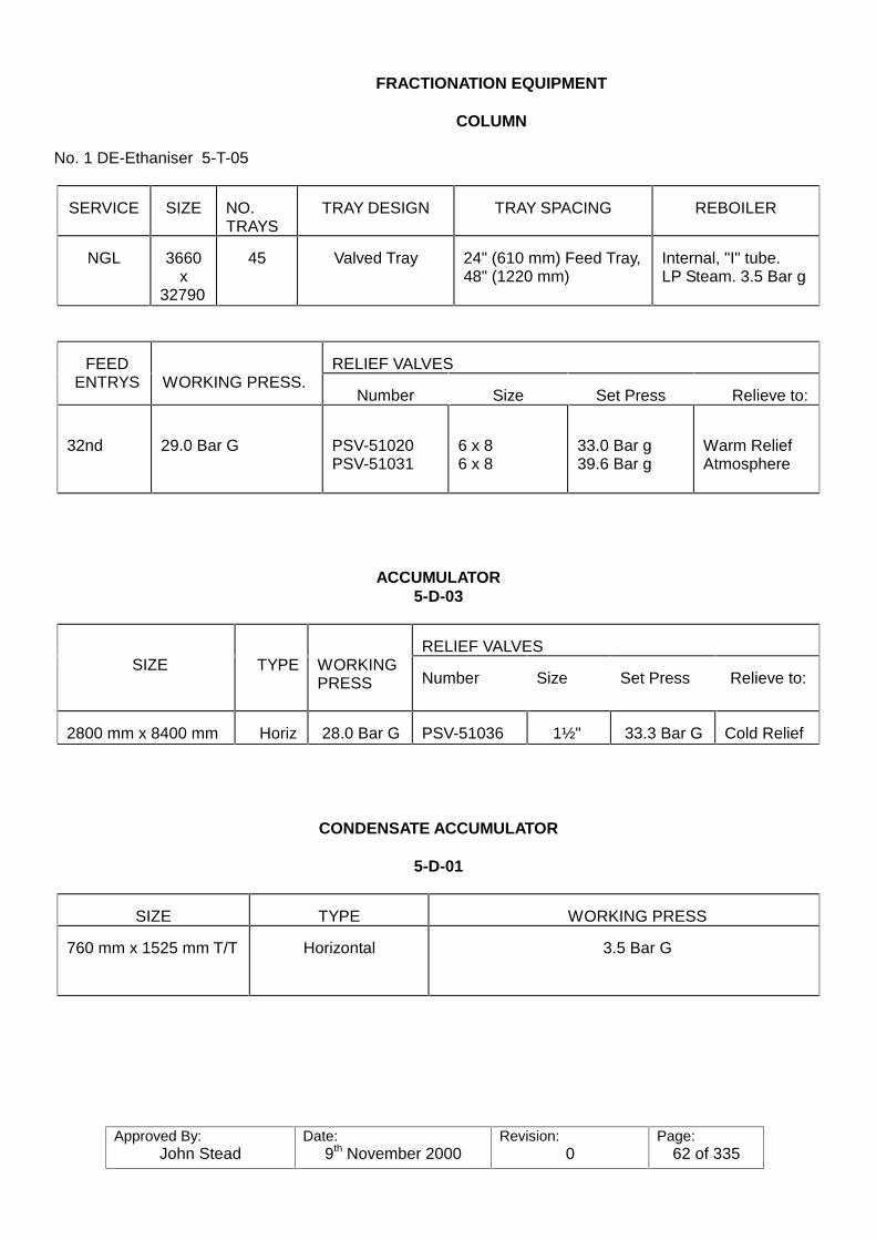
Approved By:John Stead
Date:9th November 2000
Revision:0
Page:62 of 335
FRACTIONATION EQUIPMENT
COLUMN
No. 1 DE-Ethaniser 5-T-05
SERVICE SIZE NO.TRAYS
TRAY DESIGN TRAY SPACING REBOILER
NGL 3660x
32790
45 Valved Tray 24" (610 mm) Feed Tray,48" (1220 mm)
Internal, "I" tube.LP Steam. 3.5 Bar g
RELIEF VALVESFEEDENTRYS WORKING PRESS.
Number Size Set Press Relieve to:
32nd 29.0 Bar G PSV-51020PSV-51031
6 x 86 x 8
33.0 Bar g39.6 Bar g
Warm ReliefAtmosphere
ACCUMULATOR5-D-03
RELIEF VALVESSIZE TYPE WORKING
PRESS Number Size Set Press Relieve to:
2800 mm x 8400 mm Horiz 28.0 Bar G PSV-51036 1½" 33.3 Bar G Cold Relief
CONDENSATE ACCUMULATOR
5-D-01
SIZE TYPE WORKING PRESS
760 mm x 1525 mm T/T Horizontal 3.5 Bar G
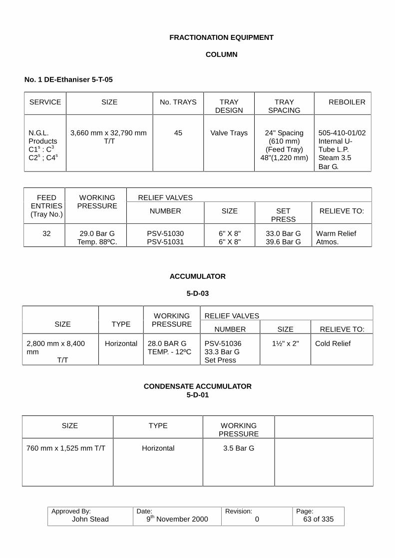
Approved By:John Stead
Date:9th November 2000
Revision:0
Page:63 of 335
FRACTIONATION EQUIPMENT
COLUMN
No. 1 DE-Ethaniser 5-T-05
SERVICE SIZE No. TRAYS TRAYDESIGN
TRAYSPACING
REBOILER
N.G.L.ProductsC1s : C3
C2s ; C4s
3,660 mm x 32,790 mmT/T
45 Valve Trays 24" Spacing(610 mm)
(Feed Tray)48"(1,220 mm)
505-410-01/02Internal U-Tube L.P.Steam 3.5Bar G.
RELIEF VALVESFEEDENTRIES(Tray No.)
WORKINGPRESSURE
NUMBER SIZE SETPRESS
RELIEVE TO:
32 29.0 Bar GTemp. 88ºC.
PSV-51030PSV-51031
6" X 8"6" X 8"
33.0 Bar G39.6 Bar G
Warm ReliefAtmos.
ACCUMULATOR
5-D-03
RELIEF VALVESSIZE TYPE
WORKINGPRESSURE
NUMBER SIZE RELIEVE TO:
2,800 mm x 8,400mm
T/T
Horizontal 28.0 BAR GTEMP. - 12ºC
PSV-5103633.3 Bar GSet Press
1½" x 2" Cold Relief
CONDENSATE ACCUMULATOR5-D-01
SIZE TYPE WORKINGPRESSURE
760 mm x 1,525 mm T/T Horizontal 3.5 Bar G

Approved By:John Stead
Date:9th November 2000
Revision:0
Page:64 of 335
FRACTIONATION EQUIPMENT
COLUMN
No. 1 DE-ETHANISER 5-T-05
SERVICE SIZE No.TRAYS
TRAYDESIGN
TRAYSPACING
REBOILER
N.G.L.ProductsC1s : C3
C2s : C4s
3,600 mm x32,790 mmT/T
45 Valve Trays 24" spacing(610 mm)
(Feed Tray)48" (1,220 mm)
505-410-01/02Internal U-Tube L.P.Steam 3.5 Bar G.
RELIEF VALVESFEEDENTRIES(Tray No.)
WORKINGPRESSURE
NUMBER SIZE SETPRESS
RELIEVETO:
32 29.0 Bar GTemp. 88ºC.
PSV-51030PSV-51031
6" X 8"6" X 8"
33.0 Bar G39.6 Bar G
Warm ReliefAtmos.
ACCUMULATOR
5-D-03
RELIEF VALVESSIZE TYPE WORKINGPRESSURE
NUMBER SIZE RELIEVE TO:
2,800 mm x 8,400 mm T/T Horizontal 28.0 Bar GTemp. -12�&
PSV-5103633.3 Bar GSet Press
1½"x2"
Cold Relief
CONDENSATE ACCUMULATOR
5-D-01
SIZE TYPE WORKINGPRESSURE
750 mm x 1,525 mm T/T Horizontal 3.5 Bar G

Approved By:John Stead
Date:9th November 2000
Revision:0
Page:65 of 335
FRACTIONATION EQUIPMENT
COLUMN
No. 2 DE-Ethaniser 5-T-06
SERVICE SIZE No. TRAYS TRAYDESIGN
TRAY SPACING REBOILER
NGL 3660 x 32790 45 Valved Tray 24" (610 mm)Feed Tray,48" (1220)
505-410-03/04Internal, "U" tubeLP Steam 3.5 Bar G
RELIEF VALVESFEEDENTRIES
WORKINGPRESSURE
NUMBER SIZE SET PRESS RELIEVE TO:
32nd 29.0 Bar G PSV-51032PSV-51032
6 x 86 x 8
33.0 Bar g39.6 Bar g
Warm ReliefAtmosphere
RELIEF VALVESFEEDENTRIES
WORKINGPRESSURE
NUMBER SIZE SET PRESS RELIEVE TO:
32nd 29.0 Bar G PSV-51032PSV-51032
6 x 86 x 8
33.0 Bar g39.6 Bar g
Warm ReliefAtmosphere
ACCUMULATOR
5-D-04
RELIEF VALVESSIZE TYPE WORKINGPRESSURE
NUMBER SIZE SETPRESS.
RELIEVE TO:
2800 mm x 400 mm Horizontal 28.0 Bar G PSV-51039 1½ 33.3 Bar G Cold Relief
CONDENSATE ACCUMULATOR5-D-02
SIZE TYPE WORKING PRESSURE
760 mm x 1525 mm T/T Horizontal 3.5 Bar G

Approved By:John Stead
Date:9th November 2000
Revision:0
Page:66 of 335
PUMPS/COMPRESSORS
(DE-ETHANIZERS)5-T-05 AND 06
SIZESERVICE NO.
SUCT. DISCH.
MAKEand
TYPE
PUMPSPEED-
RPM
SUCTIONPRESSURE
DISCHARGEPRESSURE
DIFF.HEAD
MIN.FLOW
MAX.FLOW
DRIVE
DE-ETHANISERREBOILERCOND.5-P-1/2/3/36
DE-ETHANISERREFLUX5-P-4/5/6/35
DE-ETHANISERFEED PUMPS53-P-1/2/3
4
4
3
3"
8"
10"
1½"
4"
6"
Ing. Rand.Cent.
Ing. Rand.Cent.
Ing. Rand.Cent
2900 RPM
2950 RPM
2950 RPM
2 Bar g.
28 Bar g.
33.64 Bar g.
6.1 Bar-g.
32 Bar-g.
38.2Note: Pumpwill shutdownat 41 Bar-g.
4.1 Bar g.
4 Bar g.
4.6 Bar g.
3.3M3/hr
24M3/hr
36M3/hr
22M3/hr
180M3/hr
273M3/hr
Electric10 H.P.motor
Electric50 H.P.motor
Electric100 H.P.
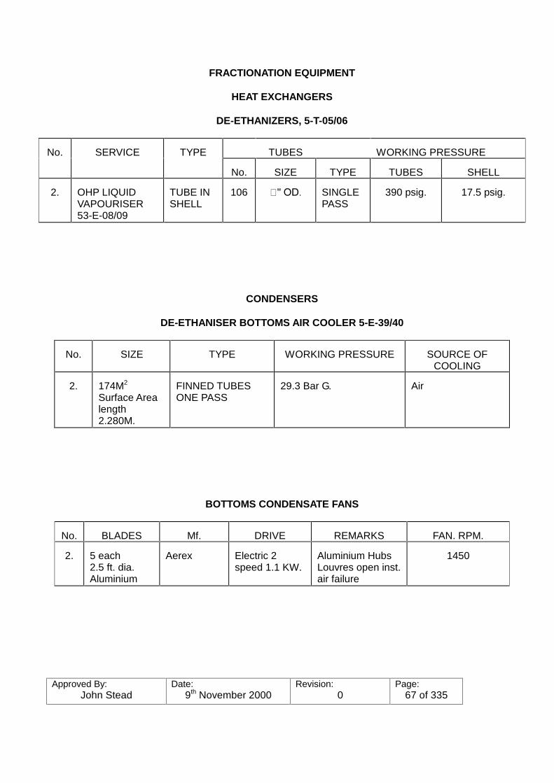
Approved By:John Stead
Date:9th November 2000
Revision:0
Page:67 of 335
FRACTIONATION EQUIPMENT
HEAT EXCHANGERS
DE-ETHANIZERS, 5-T-05/06
TUBES WORKING PRESSURENo. SERVICE TYPE
No. SIZE TYPE TUBES SHELL
2. OHP LIQUIDVAPOURISER53-E-08/09
TUBE INSHELL
106 ���2'� SINGLEPASS
390 psig. 17.5 psig.
CONDENSERS
DE-ETHANISER BOTTOMS AIR COOLER 5-E-39/40
No. SIZE TYPE WORKING PRESSURE SOURCE OFCOOLING
2. 174M2
Surface Arealength2.280M.
FINNED TUBESONE PASS
29.3 Bar G. Air
BOTTOMS CONDENSATE FANS
No. BLADES Mf. DRIVE REMARKS FAN. RPM.
2. 5 each2.5 ft. dia.Aluminium
Aerex Electric 2speed 1.1 KW.
Aluminium HubsLouvres open inst.air failure
1450
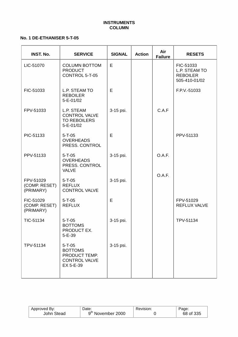
Approved By:John Stead
Date:9th November 2000
Revision:0
Page:68 of 335
INSTRUMENTSCOLUMN
No. 1 DE-ETHANISER 5-T-05
INST. No. SERVICE SIGNAL Action AirFailure RESETS
LIC-51070
FIC-51033
FPV-51033
PIC-51133
PPV-51133
FPV-51029(COMP. RESET)(PRIMARY)
FIC-51029(COMP. RESET)(PRIMARY)
TIC-51134
TPV-51134
COLUMN BOTTOMPRODUCTCONTROL 5-T-05
L.P. STEAM TOREBOILER5-E-01/02
L.P. STEAMCONTROL VALVETO REBOILERS5-E-01/02
5-T-05OVERHEADSPRESS. CONTROL
5-T-05OVERHEADSPRESS. CONTROLVALVE
5-T-05REFLUXCONTROL VALVE
5-T-05REFLUX
5-T-05BOTTOMSPRODUCT EX.5-E-39
5-T-05BOTTOMSPRODUCT TEMP.CONTROL VALVEEX 5-E-39
E
E
3-15 psi.
E
3-15 psi.
3-15 psi.
E
3-15 psi.
3-15 psi.
C.A.F
O.A.F.
O.A.F.
FIC-51033L.P. STEAM TOREBOILER505-410-01/02
F.P.V.-51033
PPV-51133
FPV-51029REFLUX VALVE
TPV-51134
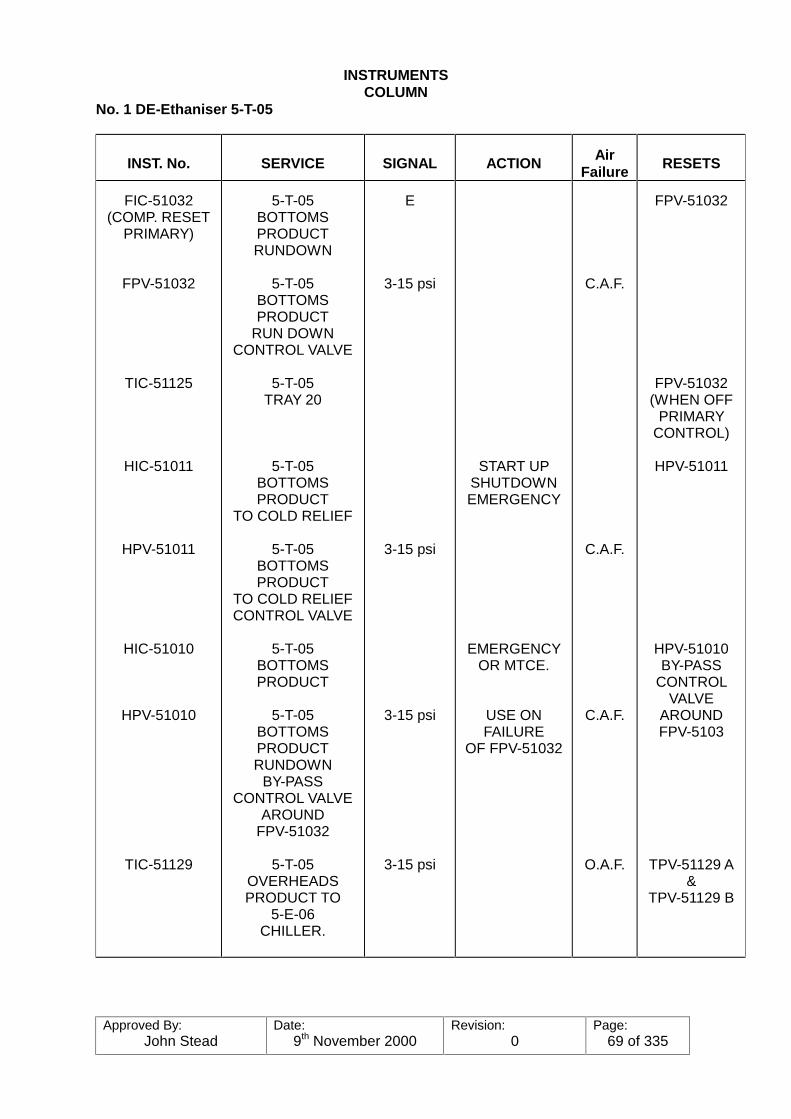
Approved By:John Stead
Date:9th November 2000
Revision:0
Page:69 of 335
INSTRUMENTSCOLUMN
No. 1 DE-Ethaniser 5-T-05
INST. No. SERVICE SIGNAL ACTION AirFailure RESETS
FIC-51032(COMP. RESET
PRIMARY)
FPV-51032
TIC-51125
HIC-51011
HPV-51011
HIC-51010
HPV-51010
TIC-51129
5-T-05BOTTOMSPRODUCTRUNDOWN
5-T-05BOTTOMSPRODUCT
RUN DOWNCONTROL VALVE
5-T-05TRAY 20
5-T-05BOTTOMSPRODUCT
TO COLD RELIEF
5-T-05BOTTOMSPRODUCT
TO COLD RELIEFCONTROL VALVE
5-T-05BOTTOMSPRODUCT
5-T-05BOTTOMSPRODUCTRUNDOWN
BY-PASSCONTROL VALVE
AROUNDFPV-51032
5-T-05OVERHEADSPRODUCT TO
5-E-06CHILLER.
E
3-15 psi
3-15 psi
3-15 psi
3-15 psi
START UPSHUTDOWNEMERGENCY
EMERGENCYOR MTCE.
USE ONFAILURE
OF FPV-51032
C.A.F.
C.A.F.
C.A.F.
O.A.F.
FPV-51032
FPV-51032(WHEN OFF
PRIMARYCONTROL)
HPV-51011
HPV-51010BY-PASS
CONTROLVALVE
AROUNDFPV-5103
TPV-51129 A&
TPV-51129 B

Approved By:John Stead
Date:9th November 2000
Revision:0
Page:70 of 335
INSTRUMENTS
No. 1 DE-Ethaniser 5-T-05
INST. No. DESCRIPTION SIGNAL ACTION Air Failure RESETS
TPV-51129 A
TPV-51129 B
PIC-51135
PPV-51135
HIC-51076
HPV-51076
LIC-51078(CASCADE)
5-T-05OVERHEADSPRODUCTCONTROLVALVEEXIT 5-E-06CHILLER
5-T-05OVERHEADSPRODUCTBY-PASSCONTROLVALVE OF5-E-06 CHILLER
5-T-05OVERHEADSACCUMULATOR5-D-03
5-T-05OVERHEADSACCUMULATORVAPOURCONTROLVALVE
5-T-05OVERHEADSTO FLAREFROM 5-D-03
5-T-05OVERHEADS(VAPOUR)ACCUMULATOR5-D-03DUMP TO COLDRELIEF
5-T-05OVERHEADSACCUMULATOR5-D-03
3-15 psi
3-15 psi
E
3-15 psi
E
3-15 psi
E
START UPSHUTDOWNEMERGENCY
O.A.F.
C.A.F.
C.A.F.
C.A.F.
PPV-51135
HPV-51076
FIC-51031

Approved By:John Stead
Date:9th November 2000
Revision:0
Page:71 of 335
INSTRUMENTS
No. 1 DE-Ethaniser 5-T-05
INST. No. DESCRIPTION SIGNAL ACTION Air Failure RESETS
FIC-51031
FPV-51031
LIC-51074
LPV-51074
PIC-51554
PPV-51554
5-T-05OVERHEADS(LIQUID)ACCUMULATOR5-D-03
5-T-05OVERHEADSACCUMULATOR5-E-03LIQUID CONTROLVALVE
5-T-05OVERHEADSREFRIGETHERMOSYPHONDRUM 54-D-01
5-T-05OVERHEADSREFRIGETHERMOSYPHONDRUM 54-D-01CONTROL VALVE
5-T-05OVERHEADSREFRIGEACCUMULATORTANK 54-D-05
5-T-05OVERHEADSREFRIGEACCUMULATORTANK 54-D-05CONTROL VALVE
E
3-15 psi
E
3-15 psi
PROCESSIMPULSE
3-15 psi
C.A.F.
C.A.F.
C.A.F.
FPV-51031
LPV-51074
PPV-51554
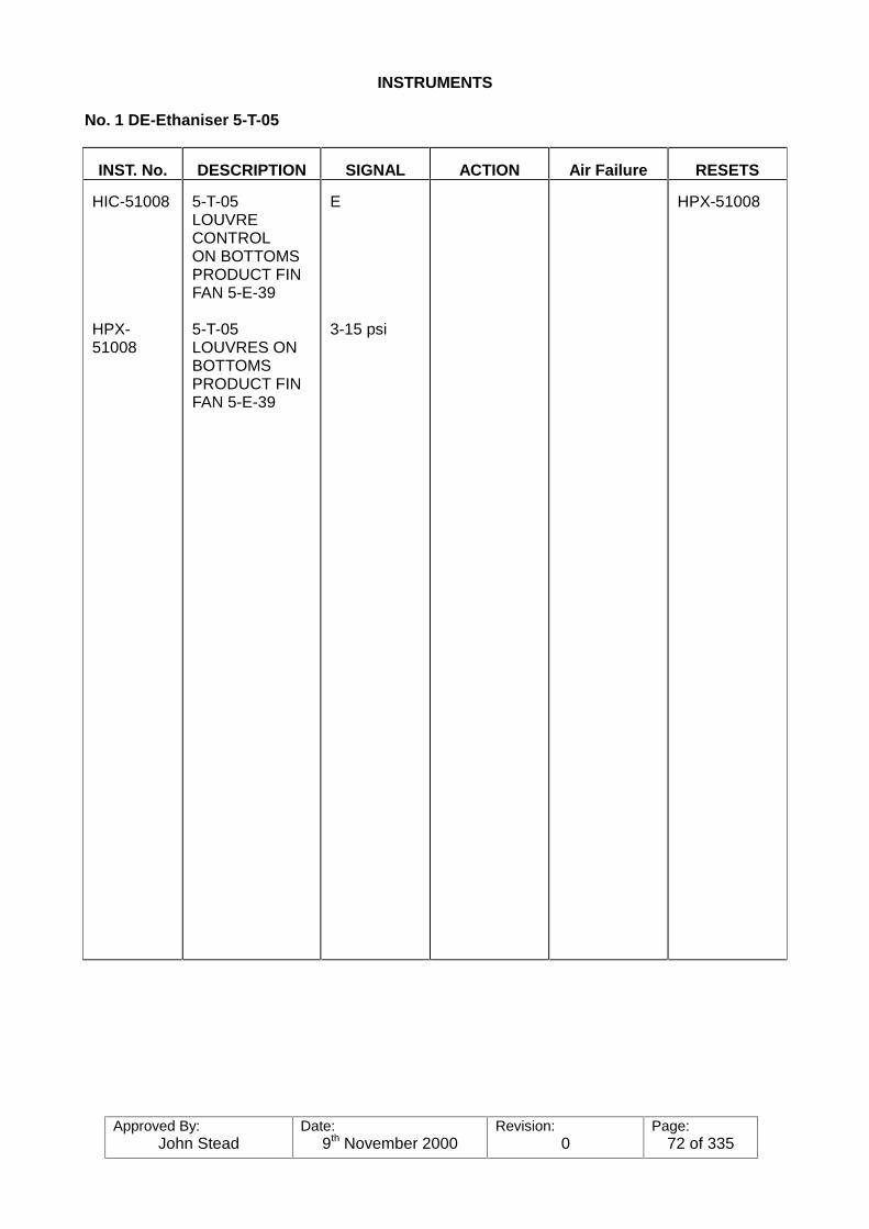
Approved By:John Stead
Date:9th November 2000
Revision:0
Page:72 of 335
INSTRUMENTS
No. 1 DE-Ethaniser 5-T-05
INST. No. DESCRIPTION SIGNAL ACTION Air Failure RESETS
HIC-51008
HPX-51008
5-T-05LOUVRECONTROLON BOTTOMSPRODUCT FINFAN 5-E-39
5-T-05LOUVRES ONBOTTOMSPRODUCT FINFAN 5-E-39
E
3-15 psi
HPX-51008
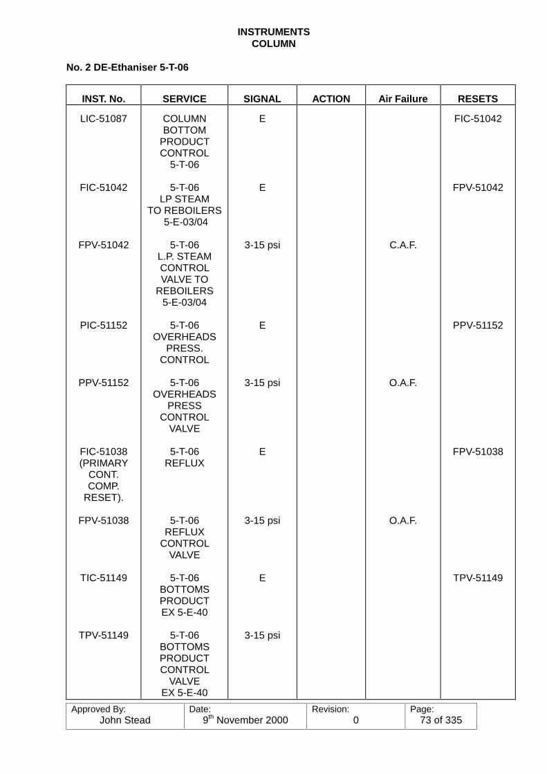
Approved By:John Stead
Date:9th November 2000
Revision:0
Page:73 of 335
INSTRUMENTSCOLUMN
No. 2 DE-Ethaniser 5-T-06
INST. No. SERVICE SIGNAL ACTION Air Failure RESETS
LIC-51087
FIC-51042
FPV-51042
PIC-51152
PPV-51152
FIC-51038(PRIMARY
CONT.COMP.
RESET).
FPV-51038
TIC-51149
TPV-51149
COLUMNBOTTOM
PRODUCTCONTROL
5-T-06
5-T-06LP STEAM
TO REBOILERS 5-E-03/04
5-T-06L.P. STEAMCONTROLVALVE TO
REBOILERS5-E-03/04
5-T-06OVERHEADS
PRESS.CONTROL
5-T-06OVERHEADS
PRESSCONTROL
VALVE
5-T-06REFLUX
5-T-06REFLUX
CONTROLVALVE
5-T-06BOTTOMSPRODUCTEX 5-E-40
5-T-06BOTTOMSPRODUCTCONTROL
VALVEEX 5-E-40
E
E
3-15 psi
E
3-15 psi
E
3-15 psi
E
3-15 psi
C.A.F.
O.A.F.
O.A.F.
FIC-51042
FPV-51042
PPV-51152
FPV-51038
TPV-51149

Approved By:John Stead
Date:9th November 2000
Revision:0
Page:74 of 335
INSTRUMENTSCOLUMN
No. 2 DE-Ethaniser 5-T-06
INST. No. SERVICE SIGNAL ACTION Air Failure RESETS
HIC-51009
HPX-51009
FIC-51041(PRIMARYCONT.COMP.RESET).
FPV-51041
TIC-51140
HIC-51013
HPV-51013
5-T-06LOUVRECONTROL ONBOTTOMSPRODUCT FINFAN 5-E-40
5-T-06LOUVRES ONBOTTOMSPRODUCT FINFAN 5-E-40
5-T-06BOTTOMSPRODUCTRUNDOWN
5-T-06BOTTOMSPRODUCTCONTROLVALVE
5-T-06TRAY 20
5-T-06BOTTOMSPRODUCT TOCOLD RELIEF
5-T-06BOTTOMSPRODUCT TOCOLD RELIEFCONTROLVALVE
E
3-15 psi
E
3-15 psi
E
E
3-15 psi
START UPSHUTDOWNEMERGENCY
C.A.F.
C.A.F.
HPX-51009
FPV-51041
FPV-51041(WHEN OFFPRIMARYCONTROL)
HPV-51013
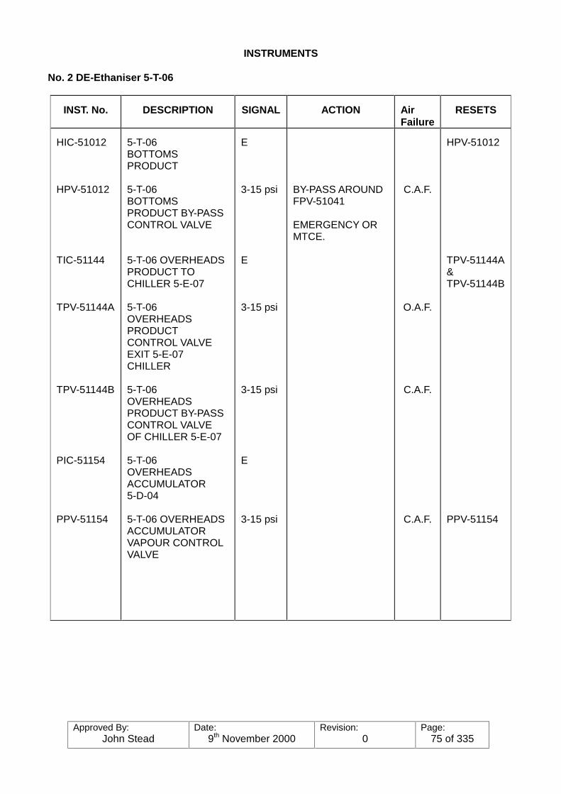
Approved By:John Stead
Date:9th November 2000
Revision:0
Page:75 of 335
INSTRUMENTS
No. 2 DE-Ethaniser 5-T-06
INST. No. DESCRIPTION SIGNAL ACTION AirFailure
RESETS
HIC-51012
HPV-51012
TIC-51144
TPV-51144A
TPV-51144B
PIC-51154
PPV-51154
5-T-06BOTTOMSPRODUCT
5-T-06BOTTOMSPRODUCT BY-PASSCONTROL VALVE
5-T-06 OVERHEADSPRODUCT TOCHILLER 5-E-07
5-T-06OVERHEADSPRODUCTCONTROL VALVEEXIT 5-E-07CHILLER
5-T-06OVERHEADSPRODUCT BY-PASSCONTROL VALVEOF CHILLER 5-E-07
5-T-06OVERHEADSACCUMULATOR5-D-04
5-T-06 OVERHEADSACCUMULATORVAPOUR CONTROLVALVE
E
3-15 psi
E
3-15 psi
3-15 psi
E
3-15 psi
BY-PASS AROUNDFPV-51041
EMERGENCY ORMTCE.
C.A.F.
O.A.F.
C.A.F.
C.A.F.
HPV-51012
TPV-51144A&TPV-51144B
PPV-51154

Approved By:John Stead
Date:9th November 2000
Revision:0
Page:76 of 335
INSTRUMENTS
No. 2 DE-Ethaniser 5-T-06
INST. No. DESCRIPTION SIGNAL ACTION Air Failure RESETS
HIC-51077
HPV-51077
LIC-51095(CASCADE)
FIC-51040
FPV-51040
LIC-51091
LPV-51091
5-T-06OVERHEADSACCUMULATOR5-D-04
5-T-06OVERHEADSACCUMULATOR5-D-04 DUMP TOCOLD RELIEF
5-T-06OVERHEADSACCUMULATOR5-D-04
5-T-06OVERHEADSACCUMULATOR5-D-04
5-T-06OVERHEADSACCUMULATOR5-D-04 LIQUIDCONTROL VALVE
5-T-06OVERHEADSREFRIGETHERMOSYPHONDRUM 54-D-22
5-T-06OVERHEADSREFRIGETHERMOSYPHONDRUM CONTROLVALVE
E
3-15 psi
E
E
3-15 psi
E
3-15 psi
START-UPSHUTDOWNEMERGENCY
C.A.F.
C.A.F.
C.A.F.
HPV-51077
FIC-51040
FPV-51040
LPV-51091
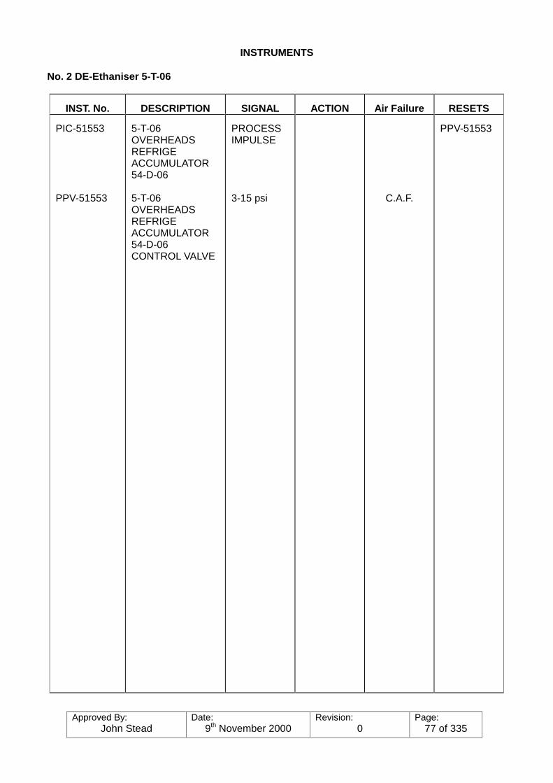
Approved By:John Stead
Date:9th November 2000
Revision:0
Page:77 of 335
INSTRUMENTS
No. 2 DE-Ethaniser 5-T-06
INST. No. DESCRIPTION SIGNAL ACTION Air Failure RESETS
PIC-51553
PPV-51553
5-T-06OVERHEADSREFRIGEACCUMULATOR54-D-06
5-T-06OVERHEADSREFRIGEACCUMULATOR54-D-06CONTROL VALVE
PROCESSIMPULSE
3-15 psi C.A.F.
PPV-51553
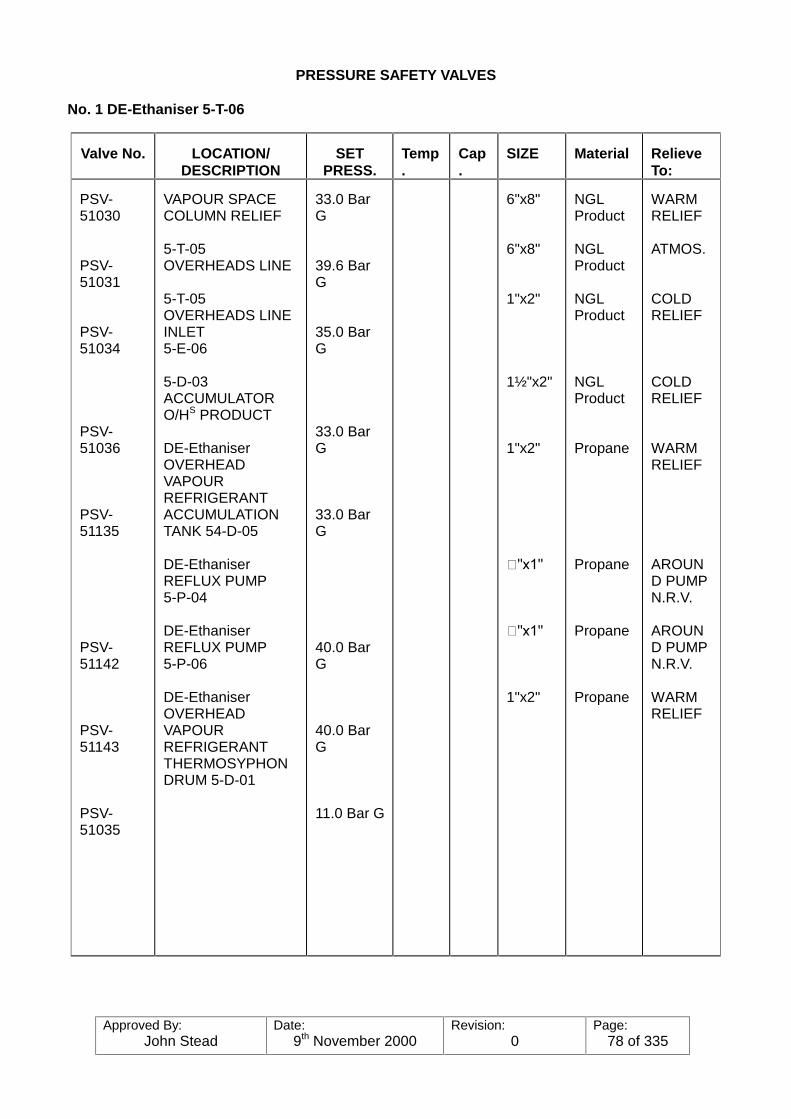
Approved By:John Stead
Date:9th November 2000
Revision:0
Page:78 of 335
PRESSURE SAFETY VALVES
No. 1 DE-Ethaniser 5-T-06
Valve No. LOCATION/DESCRIPTION
SETPRESS.
Temp.
Cap.
SIZE Material RelieveTo:
PSV-51030
PSV-51031
PSV-51034
PSV-51036
PSV-51135
PSV-51142
PSV-51143
PSV-51035
VAPOUR SPACECOLUMN RELIEF
5-T-05OVERHEADS LINE
5-T-05OVERHEADS LINEINLET5-E-06
5-D-03ACCUMULATORO/HS PRODUCT
DE-EthaniserOVERHEADVAPOURREFRIGERANTACCUMULATIONTANK 54-D-05
DE-EthaniserREFLUX PUMP5-P-04
DE-EthaniserREFLUX PUMP5-P-06
DE-EthaniserOVERHEADVAPOURREFRIGERANTTHERMOSYPHONDRUM 5-D-01
33.0 BarG
39.6 BarG
35.0 BarG
33.0 BarG
33.0 BarG
40.0 BarG
40.0 BarG
11.0 Bar G
6"x8"
6"x8"
1"x2"
1½"x2"
1"x2"
��[��
��[��
1"x2"
NGLProduct
NGLProduct
NGLProduct
NGLProduct
Propane
Propane
Propane
Propane
WARMRELIEF
ATMOS.
COLDRELIEF
COLDRELIEF
WARMRELIEF
AROUND PUMPN.R.V.
AROUND PUMPN.R.V.
WARMRELIEF

Approved By:John Stead
Date:9th November 2000
Revision:0
Page:79 of 335
PRESSURE SAFETY VALVES
No. 2 DE-Ethaniser 5-T-06
ValveNo.
LOCATION/DESCRIPTION
SETPRESS.
Temp.
Cap. SIZE Material Relieve To:
PSV-51032
PSV-51033
PSV-51037
PSV-51039
PSV-51144
PSV-51145
PSV-51038
PSV-51136
PSV-51232
VAPOUR SPACECOLUMN RELIEF
5-T-06 OVERHEADSLINE
5-T-06 OVERHEADSLINE INLET 5-E-07
DE-EthaniserOVERHEADSPRODUCTACCUMULATOR5-D-04
DE-EthaniserREFLUX PUMP5-P-05
DE-EthaniserREFLUX PUMP5-P-35
DE-EthaniserOVERHEADVAPOURREFRIGERANTTHERMOSYPHONDRUM 54-D-02
DE-EthaniserOVERHEADVAPOURREFRIGERANTACCUMULATIONTANK 5-D-06
De-EthaniserOVERHEAD LIQUIDPRODUCT EX.5-D-04
33.0 Bar G
39.6 Bar G
35.0 Bar G
33.0 Bar G
40.0 Bar G
40.0 Bar G
11.0 Bar G
33.0 Bar G
40.0 Bar G
6"x8"
6"x8"
1"x2"
1½"x2"
¾"x1"
¾"x1"
1"x2"
1"x2"
¾"x1"
NGLProduct
NGLproduct
NGLProduct
NGLProduct
Propane
Propane
Propane
Propane
Propane
WARMRELIEF
ATMOS.
COLDRELIEF
COLDRELIEF
AROUNDPUMPN.R.V.
AROUNDPUMPN.R.V.
WARMRELIEF
WARMRELIEF
ATMOS.
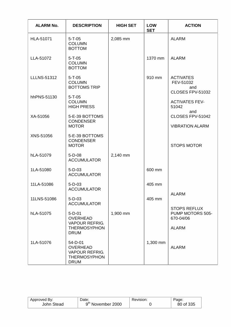
Approved By:John Stead
Date:9th November 2000
Revision:0
Page:80 of 335
ALARM No. DESCRIPTION HIGH SET LOWSET
ACTION
HLA-51071
LLA-51072
LLLNS-51312
hhPNS-51130
XA-51056
XNS-51056
hLA-51079
1LA-51080
11LA-51086
11LNS-51086
hLA-51075
1LA-51076
5-T-05COLUMNBOTTOM
5-T-05COLUMNBOTTOM
5-T-05COLUMNBOTTOMS TRIP
5-T-05COLUMNHIGH PRESS
5-E-39 BOTTOMSCONDENSERMOTOR
5-E-39 BOTTOMSCONDENSERMOTOR
5-D-08ACCUMULATOR
5-D-03ACCUMULATOR
5-D-03ACCUMULATOR
5-D-03ACCUMULATOR
5-D-01OVERHEADVAPOUR REFRIG.THERMOSYPHONDRUM
54-D-01OVERHEADVAPOUR REFRIG.THERMOSYPHONDRUM
2,085 mm
2,140 mm
1,900 mm
1370 mm
910 mm
600 mm
405 mm
405 mm
1,300 mm
ALARM
ALARM
ACTIVATES FEV-51032
andCLOSES FPV-51032
ACTIVATES FEV-51042
andCLOSES FPV-51042
VIBRATION ALARM
STOPS MOTOR
ALARM
STOPS REFLUXPUMP MOTORS 505-670-04/06
ALARM
ALARM
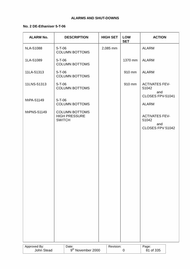
Approved By:John Stead
Date:9th November 2000
Revision:0
Page:81 of 335
ALARMS AND SHUT-DOWNS
No. 2 DE-Ethaniser 5-T-06
ALARM No. DESCRIPTION HIGH SET LOWSET
ACTION
hLA-51088
1LA-51089
11LA-51313
11LNS-51313
hhPA-51149
hhPNS-51149
5-T-06COLUMN BOTTOMS
5-T-06COLUMN BOTTOMS
5-T-06COLUMN BOTTOMS
5-T-06COLUMN BOTTOMS
5-T-06COLUMN BOTTOMS
COLUMN BOTTOMSHIGH PRESSURESWITCH
2,085 mm
1370 mm
910 mm
910 mm
ALARM
ALARM
ALARM
ACTIVATES FEV-51042
andCLOSES FPV-51041
ALARM
ACTIVATES FEV-51042
andCLOSES FPV 51042
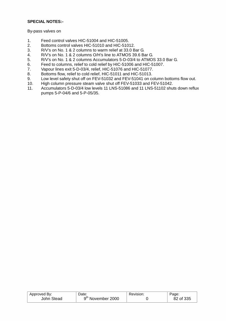
Approved By:John Stead
Date:9th November 2000
Revision:0
Page:82 of 335
SPECIAL NOTES:-
By-pass valves on
1. Feed control valves HIC-51004 and HIC-51005.2. Bottoms control valves HIC-51010 and HIC-51012.3. R/V’s on No. 1 & 2 columns to warm relief at 33.0 Bar G.4. R/V’s on No. 1 & 2 columns O/H’s line to ATMOS 39.6 Bar G.5. R/V’s on No. 1 & 2 columns Accumulators 5-D-03/4 to ATMOS 33.0 Bar G.6. Feed to columns, relief to cold relief by HIC-51006 and HIC-51007.7. Vapour lines exit 5-D-03/4, relief, HIC-51076 and HIC-51077.8. Bottoms flow, relief to cold relief, HIC-51011 and HIC-51013.9. Low level safety shut off on FEV-51032 and FEV-51041 on column bottoms flow out.10. High column pressure steam valve shut off FEV-51033 and FEV-51042.11. Accumulators 5-D-03/4 low levels 11 LNS-51086 and 11 LNS-51102 shuts down reflux
pumps 5-P-04/6 and 5-P-05/35.

Approved By:John Stead
Date:9th November 2000
Revision:0
Page:83 of 335
NORTH SEA PETROLEUM - TEESSIDE OPERATIONS
DE-ETHANISER OVERHEAD AMINE PRODUCT TREATERSP & ID 7809-509-D00-001 to 007
Purpose of the System:
The treater will remove hydrogen sulphide and carbon dioxide from the de-ethaniser overheadproduct, which will permit the manufactures of on specification product ethane in thedownstream units. To achieve on specification products, the treated gas leaving the aminecontactor should contain a maximum of 0.25gr H2S per 100ft3 and 1500 ppm CO2. Exceedingthese amounts could result in production of off specification ethane product, which would thenhave to be flared.
Extent of the System
The system starts with the vapour and liquid lines leaving the de-ethaniser overhead refluxaccumulators (2 of), and the regeneration gas line leaving the de-ethaniser overhead productde-hydrator treater. Included in the system is the following equipment:-A. Glycol Heater and Pumps.B. De-ethaniser Overhead Liquid Vapouriser and Spare.C. Treater Feed Heater and Spare.D. Amine Storage Tank.E. Inlet Scrubber.F. Amine Contactor-Outlet Scrubber (3 of).G. Amine Surge Tank (3 of).
Amine Surge Tank Pumps (6 of) .H. Amine Coolers (3 of).I. Amine Heat Exchangers (3 of).J. Amine Still (3 of).K. Amine Still Kettle (3 of).L. Amine Still Overhead Condensers (3 of).M. Amine Still Overhead Reflux Accumulators (3 of).N. Amine Still Overhead Reflux Accumulators Pumps (6 of).
The system ends at the three gas outlet lines from the outlet scrubbers, and the acid gas outletlines from the three amine still reflux accumulators
Process Description
The de-ethaniser overhead liquid product is vapourised in the de-ethaniser overhead liquidvapourisers, then mixed with the de-ethaniser overhead vapour product and superheated in thetreater feed heaters. As the vapours pass form the feed heaters, the regeneration gas from thede-ethaniser overhead dehydrators mix together and flow into the inlet scrubber. As the gasleaves the scrubber it is divided evenly to the three amine contactors, where the hydrogensulphide and carbon dioxide are removed by contacting the gas vapour stream withdiethanolamine (D.E.A) which has the properties of absorbing the impurities H2S and CO2, theD.E.A being circulated over the contactor as a form of reflux.
On leaving the top D.E.A contactor, the treated gases are passed to the outlet scrubber wheretraces of D.E.A carry-over are knocked out, the treated gas then being piped to the de-ethaniseroverhead product dehydrators for the removal of moisture content. The foul D.E.A is transferredunder controlled conditions to the D.E.A still.

Approved By:John Stead
Date:9th November 2000
Revision:0
Page:84 of 335
In the D.E.A still, the foul D.E.A is regenerated by the use of controlled re-boil system wherebythe foul acid gases, H2S and CO2, are taken over the top of the still to be cooled then scrubbedin the reflux accumulator and finally the acid gases are burnt in the acid gas incinerator (see AcidGas Incinerator).
The regenerated D.E.A is taken from the bottom of the overflow wire section of the kettle reboiler,and piped under controlled conditions to the amine surge to be re-used in the D.E.A contactor.
Process Flow Control (refer to Fig. No.1)
This pre-heating system is common for all three product treaters.
The de-ethaniser overhead liquid product from both de-ethaniser columns, at a temperature of10.4oF (-12oC) and pressure of 24 Bar G (392 psi), flows through the tube side of vapouriser 5-E-08 where the liquid is vapourised by circulating hot glycol at 149oF (65oC) through the shell sideof vapouriser 5-E-08.
As the gas vapours leave the vapouriser, they are mixed with the de-ethaniser overhead vapoursfrom both columns, and passed through the tube side of an LP steam superheater, the vapoursbeing superheated to an operating temperature of approximately 95oF (35oC). A temperaturecontrol system is positioned on the gas vapour exit line TIC-51161, which re-sets a control valveTPV-51161 situated in the LP steam line. Depending on process conditions, steam is allowedto flow through the shell side 51-E-01 the condensate being trapped, and discharging to the LPcondensate system.
The now superheated gas vapours flow into the inlet scrubber 5-D-01 via an 8 inch line, wherethe vapours are scrubbed of any entrained liquids and then, pass out via a 10 inch line whichsplits into three identically sized 8 inch lines to feed Nos 1,2 and 3 D.E.A contactors, the flowsbeing proportioned evenly by the use of a flow indication control system on the outlet of eachamine contactor outlet scrubber.
The inlet scrubber 51-D-01 is fitted with sight glasses and any accumulated levels of liquidhydrocarbon are pressured to the cold flare system. Here a high level switch HLNS-5114 willoperate on high level, and transmit a signal through LEV-51109 to a control valve LPV-51109which is positioned on the outlet line from the bottom of the scrubber. As the liquid level ispressed to the cold flare system, a level switch 1LNS-51109 will close off the control valve LPV-51109. The regenerated gas re-cycle is mixed with the gas vapour prior to entering the inletscrubber.
The glycol heating system and the amine storage tank will be discussed later.
Amine Contactor (refer to Fig. No. 2)
This description refers to No. 1 stream south, the other two streams are identical in operation.
The D.E.A contactor/outlet scrubber is two stage column, the purified gas passing from the topof the contactor into the outlet scrubber and finally to the downstream dehydrator.
The de-ethaniser overhead product from the inlet scrubber enters the amine contactor at thebase of the column. The contactor product operates with a normal level of D.E.A solution, andthere are 22 bubble cap trays. As the gas vapours pass up the column and through the trays,they are constantly in contact with the D.E.A solution. The H2S and CO2 in the gas vapour are,therefore, absorbed by the constantly circulating D.E.A solution.
Approved By:John Stead
Date:9th November 2000
Revision:0
Page:85 of 335
As the gas vapour (now stripped of H2S and CO2) pass out of the top of the D.E.A contactor, theyflow into the outlet scrubber, where any entrained D.E.A is removed by a stainless steel mistextractor. In order to control the flow of gas and the operating pressure of the contactor, acontrol valve is positioned in the outlet gas line. Here a flow element FNT-51050 relays a signalto FIC-51050, which is converted to a pneumatic by FNX-51050. This pneumatic signal thenoperates the flow control valve FPV-51050. To hold an operating pressure of 22 Bar G in thesystem, a pressure transmitter PNT-51180 relays a signal to PIC-51180 which re-sets FIC-51050. An analytical instrument AE-51009 alarms on high H2S content. The vapours then passon to the dehydrating unit. In the event of a build up of liquid level in the scrubber, high levelalarm switch hLNS-51112 is activated. The level can be blown via a 2" line to the D.E.A still. D.E.A. carryover into the gas stream will result in plugging of the tubes on the overhead treatersregeneration gas coolers.
The circulating D.E.A is taken under controlled conditions from the D.E.A surge tank 51-D-13.The electrically driven circulating pumps, 51-P-04 or 51-P-05, take suction and deliver the leanD.E.A to the 22nd tray in the contractor. For controlled operating conditions, a flow instrumentFIC-51051 is used to re-set a control valve FPV-51051. In the event of upset conditions, veryoften due to foaming in the control valve, a differential point between these points is relayed tothe Control Room by dPR-51177 and corrective action can be taken.
The surge tank operators at atmospheric pressure and is supplied with a fuel gas purge forblanketing, the flow being measured on FI-51056, the excess gas venting to the atmosphere. Sight glasses are fitted for visual observation of levels, and high and low level switches, HLNS-5116 and LLNS-51117, are also supplied. Facilities are also supplied for the addition of sodaash to maintain a control on the pH of the lean D.E.A. To minimise foaming in the contactor asludge free D.E.A system is maintained by passing a slip stream of D.E.A off the circulationpump discharge 51-P-04/05 through a cartridge type filter, and a activated charcoal filter, the flowbeing measured on FI-51054. The filtered D.E.A. is then re-routed back to the surge tank 51-D13.
In the event of foaming problems, an anti-foam tank,51-D-20, is supplied. An electrically drivenpositive displacement pump, 51-P-01, is used for metering the injection rate of anti-foamsolution, which is delivered into the lean D.E.A. solution line on the circulating pumps discharge.
The lean D.E.A. returning from the D.E.A. still, passes through the shell side of heat exchangers51-E-06/07/08, pre-heating the foul D.E.A. going to the D.E.A. still. In order to achieve anoperating temperature of 100oF (38oC) on the lean D.E.A. to the surge tank, a fin-fin cooler, issupplied, which effectively reduces the D.E.A. temperature from 117oC to 38oC. To achieve thistrim control HIC-51020 operates a set of adjustable louvres. A motor driven fan is also available,where the fan can be operated on high/low speed or, can be stopped. The selection buttonsbeing in the control Room. Any vibration on the motor, XNS-5176, will trip the cooler to hold acontrolled level of D.E.A. in the D.E.A> still. Low pressure condensate facilities are provided tohold the D.E.A. solution at the correct operating strength.
The foul D.E.A. solution on leaving the contractor at a temperature of 140oF (60oC), flowsthrough the tube side of heat exchanges 51-E-06/07/08), where it is pre-heated to a temperatureof 210oF (99oC) and then fed forward to the D.E.A. still. A torque tube arrangement for bottomlevel control LNT-5110 relays a signal to LIC-5110, the signal from this is converted to apneumatic signal by LNX-5110. The pneumatic air signal then re-sets a level control valve LPV-51110 on the foul D.E.A. line downstream of the feed pre-heaters.
D.E.A. Regeneration (refer to Fig. No. 3)
This description refers to stream No. 1 south. The other two streams being identical inoperation.
Approved By:John Stead
Date:9th November 2000
Revision:0
Page:86 of 335
Flow Control
The foul D.E.A. solution after passing through the pre-heat exchanges, enters the D.E.A. still atthe 22nd tray at a temperature of 99oC. The still has 22 stainless steel valve trays, the bottomtray No. 1, overflows into a seal pan with wire plate, which is positioned such to avoid vapourimpingement from the reboil vapours. To attain the removal of the acid gases, H2S and Co2 fromthe foul D.E.A. solution, an external type reboil kettle is used, the reboil agent being LP steam.The level control is positioned on the reboiler to hold controlled conditions in the kettle and still.A tube bundle is fitted in the kettle, where the LP steam passes through the tube side on flowcontrol. An injection of condensate is provided for de-superheating and dilution of the D.E.A.if required. Any accumulated water or D.E.A. is pumped back as reflux.
On the LP steam supply, FIC-51081 re-sets a control valve, FPV-51081. Downstream, TIC-51178 re-sets a control valve, TPV-5178, where condensate at 6.1 Bar G (87 psi) is injected asa de-superheating agent. The condensed steam form the steam bundle is collected incondensate pot 51-D-16. Condensate pumps 51-P-10/11, pump the condensate to the LPsystem on level control. Here a torque tube instrument LNC-51125 re-sets a control valve onthe pump discharge LPV-51125 to hold a constant level in 51-D-16. A slip stream is taken offupstream of the level control valve which is used as the de-superheating agent on the LPreboiler steam supply.
An overflow wire is positioned at the back of the steam bundle where the lean D.E.A. in thereboiler overflows and passes out of the bundle where it is piped to the lean D.E.A. surge tank.The level of lean D.E.A. in the kettle (and the still) is controlled by LIC-51121 re-setting a controlvalve LPV-51121 on the exit of the D.E.A. cooler 51-E-03. Facilities are provided for the injectionof condensate (from the de-superheater supply) to hold the D.E.A. concentration by dilution,which will also keep the level up in the D.E.A. surge tank. The condensate when required ismeasured on FI-51055.
Sufficient steam is supplied to the reboil kettle by FIC-51081 to hold a boil-up temperature of118oC at 0.8 Bar G (13 psi). As the D.E.A. vapours flow from the reboiler they pass into theD.E.A. still below the first tray. As boil-up is achieved, the H2S and CO2 are stripped out of thefoul D.E.A. solution flowing down the column, the removed acid gases plus entrainedcondensate and D.E.A. pass from the top of the column at a temperature of 107oC. Theoverhead vapours are passed through a fin fan cooler, 51-E-03/04/05, where the temperatureis reduced to 38oC. To achieve this a motor driven fan is used. A shut switch XNS-51179 tripsthe motor on excessive vibration. For trim control, adjustable louvres are supplied operated byTIC-51023.
The outlet line form 51-E12, flows into the reflux accumulator 51-D-19. The acid gas vapoursare scrubbed by a stainless steel mist extractor and then are piped forward to be burnt in theacid gas incinerator. A control valve is positioned in the acid gas exit line, where a pressureinstrument PIC-51194 re-sets a control valve PPV-51194 to hold a back pressure of 0.45 Bar G(6 psi) in the reflux accumulator. The condensed product in the accumulator, i.e D.E.A. andcondensate, is let out on level control and used as a reflux. Electrically driven pumps 51-P-16/17take suction from 51-D-19 and pump the reflux forward where it joins up with the foul D.E.A.solution downstream of LPV-51110. The reflux is fed forward on level control, where the controlvalve LPV-51122 is re-set by the accumulator level controllerLIC-5112.
Approved By:John Stead
Date:9th November 2000
Revision:0
Page:87 of 335
Glycol Heating System (refer to Fig. No. 1)
Purpose:
In order to ensure that the de-ethaniser overhead liquid is totally vapourised prior to treating, aset of two vapourisers, one on line and one spare, have been supplied where a glycol solutionis used as a heating medium. The closed glycol system was chosen because the high heattransfer rate and low temperature levels in the exchange, could result in freezing if steam hadbeen used. In order to attain the required heat for vaporisation of the liquid feed, the glycol isheated by LP steam.
Flow Control
The glycol used in the system is heated to an operating temperature of 66oC in the glycol surgetank 51-D-26. In order to achieve this, LP steam is passed through a tube bundle 51-E-15. Atemperature control TIC-51222 receives a signal from a temperature element 51-D-26 and re-sets a control valve TPV-51222 on the steam to 51-E-15. The condensate is trapped and thendischarged to the 1.7 Bar G (26 psi) condensate header.
A baffle plate is positioned between the head of 51-E-15 and the suction line vortex breaker. The heated glycol is discharged at a pressure of 1.2 Bar G (18 psi) and flows through the shellside of the liquid feed vapouriser 5-E-08 or 09, returning to the heating side of the surge tank 51-D-26 at a temperature of approximately 30oC, where it is reheated. As the glycol system is aclosed circuit and is kept at a constant operating temperature, no controls have been supplied.However, the surge tank is fitted with a level glass and high and low level switches, HLNS-51183and LLNS-51185. To help prevent corrosion, a sample is taken twice weekly, and as the PH ofthe circulating glycol falls off, NIACORR is added from an inhibitor pot. Facilities are providedfor the addition of fresh glycol solution if required.
D.E.A. Storage Tank:
At various intervals fresh D.E.A. will be required in the treaters, either through loss byentrainment or decomposition. In order to do this a D.E.A. storage tank is supplied, where fuelgas is used to blanket the D.E.A. and also keep a constant working pressure in the storage tank,the excess venting to the incinerator and burnt. A steam coil is fitted inside the tank and 3.5 BarG condensate is used to maintain the 100% strength D.E.A. at about 45oC, discharging to the1.7 Bar G condensate header.
Tank Control:
The storage tank 51-D-10 is fitted with level glasses and if the level is noted to be low, fresh100% D.E.A. is charge to 51-D-10 by road tanker via 4 inch line.
On 51-D-10 a pressure control instrument PIC-51242 operates on a split range system twocontrol valves. Fuel gas is supplied to 51-D-10 to hold a pressure of 2.5 Bar G (36 psi) wherePPV-51242A working on a 3-9 psi signal opens to admit the gas, and PPV-51242B working ona 9-15 signal opens to vet excess pressure to the amine incinerator.
If fresh inventory of D.E.A. is required in any one of the three treaters, the D.E.A. is pressuredforward to the relevant D.E.A. surge tank.
3 diags.
Approved By:John Stead
Date:9th November 2000
Revision:0
Page:88 of 335
4. SPECIAL NOTES
Foaming
Can be caused by:a) Liquid hydrocarbons entering the D.E.A. solution (probably due to problems
upstream)b) Poor operation of D.E.A. filters.
Action:1) Injection of antifoam agent, as required.2) Check operation of filters, clean as required.3) Increase feed inlet gas temperature.
H2S Breakthrough:
H2S analyser will alarm at ��JUDLQ�DQG���JUDLQ�+2S per 100ft3.
Cause:a) Low D.E.A. circulation on contactor.b) Poor stripping rate on D.E.A. regenerator.
Action:1) Increase lean D.E.A. circulation to contactor.2) Increase stripping rate on D.E.A. regenerator.
Acid Gas Removal:
While complete removal of acid gas is impractical, removal down to 30-60 grains (0.05-0.10scf) per gallon of D.E.A. solution should be achieved. Any appreciable increase inthis residual will decrease the acid gas removal in the contactor. A high residual willindicate that more acid gas, primarily carbon dioxide, is entering the reboiler and beingevolved. This higher concentration of hot acid gases will cause corrosion and erosionof the reboiler, its tubes ad the still.
Another possible trouble spot in the regenerator still is the reflux system. H2S, CO2 andwater are main constituents in the regenerator overhead vapours. Small amounts ofD.E.A. carry over in the condensed reflux, will provide a sufficient corrosion inhibitor inthe overheads equipment. The concentration will be approximately 0.5% D.E.A. Higherconcentrations will result in D.E.A. losses and poor stripping due to possible foaming. Antifoam injection would help this problem.
Control tests to be run each day on the treater are, D.E.A. concentration (approx. 30%),acid gas content of foul and lean D.E.A. streams.
If the D.E.A. content of the solution falls below 30%, fresh D.E.A. should be added.
If acid gas content of the lean solution gets above 60 grains (0.1 scf) per gallon, increasereboil rate in regenerator.
Steam condensate should be added to the solution as needed to keep the level up inD.E.A. surge tank. This is done using 6.1 Bar G condensate and injecting into leanD.E.A. line from 509-950-23 to reboil kettle, 509-410-09. The flow is measured on FI-51055, using a needle valve for fine adjustment.
Approved By:John Stead
Date:9th November 2000
Revision:0
Page:89 of 335
DE-ETHANISER OVERHEAD VAPOUR DEHYDRATOR/TREATERS(P & ID Ref. 7809-519-D00-006)
Introduction
The treater/dehydrators will remove water and any residual hydrogen sulphide from the de-ethaniser overhead products to provide a suitable feed for the Demethaniser tower.
Specifications for the feed product to the Demethaniser are 1ppm water and 1 ppm hydrogensulphide. If the water content is high, downstream equipment could plug with hydrateformations. If the H2S (Hydrogen Sulphide) is too high, the ethane product will be offspecifications, and therefore unsaleable.
This section includes the following:De-ethaniser Overhead Dehydrator Towers 53-T-20/21/22/23De-ethaniser Overhead Dehydrator Dust Filter 53-FI-05De-ethaniser Overhead Dehydrator Regen. Heaters 53-E-09/10/27/28/29/34De-ethaniser Overhead Dehydrator Fan Coolers 53-E-07/08De-ethaniser Overhead Dehydrator Regen. Separator 53-D-24
Flow Description
Wet De-ethaniser overhead product from the outlet scrubbers of the treater flows into a commonheader (10") at 47,900 NM3/HR. and 25. Bar G at 38oC, and is composed of ethane, andmethane. The primary process conditions, i.e. flow, pressure and temperature, are controlledby other units and cannot be directly changed y the dehydrator unit. However, the flow throughthe two dehydrators on line should be adjusted manually by using the outlet block valves toensure each dehydrator has the same flow and sharing the drying load equally. Flow indicatorsare supplied on each dehydrator for this purpose.
There are four dehydrators in this section and two will work in parallel when drying, while theother two will be in different stages of regeneration, or on stand-by.
The dehydrators are vertically mounted vessels approximately 24’ x 6’ 6" and filled with adesiccant called L.B. Davidson 614 Mol Sieves. A molecular sieve is an extruded pellet in whichthe pores of the pellet can be different sizes to absorb different materials. The pellets in thesedehydrators have been designed ad made with a pore size to absorb moisture (H2O) andhydrogen sulphide (H2S). This desiccant is supported by a layer of ¼" alumina balls which aresupported by a layer of ½" alumina balls.
The NGL vapours pass through the desiccant, and any moisture, or traces of H2S will beabsorbed on the pores of the desiccant.
Normal flow through the dehydrators is from TOP to BOTTOM. The dry vapour exits at thebottom and joins a common header, (10"), with the flow from the outer "On Line" dehydrator. Itthen enters a dust filter which filters out any desiccant or other dust which may get past thedehydrators. There is only one dust filter supplied, therefore, it will have to be bypassed forcleaning or changing cartridges. After the dust filter the vapour is sampled for moisture contentwith an "in line" analyser, AE-51068, which will indicate and alarm on high water content in thecontrol room. The vapour then flows directly to the first Demethaniser feed heat exchanger, 5-E-10.
Approved By:John Stead
Date:9th November 2000
Revision:0
Page:90 of 335
Regeneration
The normal cycle for the dehydrators is controlled automatically by an automatic sequence timer,which will start and stop the compressors, establish and maintain flows temperatures, andchange over the dehydrators at the end of each step or cycle. Normal cycles are:On stream (Drying) - 16 hoursHeating - 4 hoursCooling - 4 hoursStand-by (or idle) - 8 hours
During normal operation the timers will be set with two dehydrators "On line" in parallel, one onregeneration (heating or cooling), and one on stand-by at any time. If one is under maintenanceor for some other reason, the timers can be set for 8 hour drying cycle with no stand-by time. The system is designed so that one dehydrator can accommodate full vapour feed rate for theDemethaniser.
Regeneration Flow
A side stream of the dry, treated vapour from the main flow, downstream of the dust filter andmoisture analyser, and used to regenerate the desiccant in the exhausted bed.
This flow is directed to the regen. heaters during the heating cycle or around the heaters for thecooling cycle.
Heating Step
There are six regeneration gas heaters. They will operate in series of three when heating, i.e53-E-10/29/30 will be in service, while 53-E-9/27/28 are on stand-by, or vice-versa. They willraise the regeneration gas flow from 38oC to approximately 315oC. 55.2 Bar G steam is usedas the heating medium.
The regeneration gas temperature must be maintained above 288oC at the outlet of thedehydrators to remove the H2S from the desiccant, which will decrease its capacity for drying andtreating on the next drying step. The regeneration vapour temperature is controlled by a splitrange controller, TRC-51244, A and B. The A valve (3-way) is on the main regeneration flow andis situated at the inlet to the regeneration heaters. This will control the relevant amount ofregeneration vapour flowing through, or by-passing the heater. When the bypass is closed (Allflow going through the heater), the B valve, which controls the flow of 55.2 Bar G steam from theheater to a 5.2 Bar G steam system, will open, allowing more steam to pass through the heater,therefore, heating up a vapour quicker. Once the temperature is raised to the set point, the Bvalve will close and the A valve will then control the temperature by allowing more or less throughthe by-pass.
The hot regeneration vapour will flow to the bottom of the dehydrator and join the normal outletline, and pass UP through the bed picking up moisture and H2S from the desiccant. The wetregeneration vapour will exit from the top of the dehydrator and flow to the regeneration coolers.
There are two regeneration gas coolers, 53-E-07/08. They are motor driven fans forcing airthrough a radiator type tube bundle. Adjustable louvres are fitted on the top which can reduceor increase the amount of air passing through the coolers allowing some degree of control overthe outlet temperature. Design temperature on the outlet is 38oC. The adjustable louvres areauto. Operated by remote controllers in the control room. (TIC-51249).
High and low temperature alarms are fitted on the outlet and will alarm in the NGL control room.During normal operation, one cooler will be in service and one on stand-by.
Approved By:John Stead
Date:9th November 2000
Revision:0
Page:91 of 335
Regeneration gas then flows to the regeneration gas separator, 53-D-24, which is a verticallymounted vessel, 8’2" x 2’6" with a demister pad fitted near the top section. The gas enters theside, flows up through the pad and exits from the top. Any liquid which collects in the bottom willbe drained off by hand. In the event of high level, a high alarm will indicate in the NGL controlroom. If the level is allowed to get any higher, it will actuate a high level alarm switch and shutdown the regeneration gas compressor. The regeneration vapour flow then carries on to thecompressors. Conditions at this point are 22.4 Bar G, 38oC and 8,300 NM3/Hr.
The regeneration compressors are provided because the premised gas analysis was changed. Originally the regeneration gas was taken from the fuel gas system (As with the propane, andbutane treaters), but later analysis showed there would not be enough fuel gas to use for allthree systems, so this was redesigned to use the dried/treated effluent gas from the dehydrators. The compressors are required purchased and their pressure rating was too low to be on thecompressor discharge side, the regeneration had to be arranged with the towers on the suctionside of the compressors. In most designs the towers would be on the discharge side, as this ismore economical.
There are two electric driven compressors, 53-C-01/02 one will be in service and the other onstand-by. They will raise the pressure enough to re-cycle to the line of the de-ethaniseroverhead inlet scrubber, 51-D-01. Discharge pressure is 27.3 Bar G at 38oC.
The flow control system is situated on the discharge line of the compressor. The flow will bemonitored and controlled by FRC-51090 "A" and "B". This is a split range controller in which the"A" valve is controlling the main flow of regeneration gas to the de-ethaniser overhead scrubber(inlet) 51-D-01.
When the compressors are out of service this valve will be in closed position and the "B" valvewill be in the open position. When the compressor starts, the "B" valve, being open, will allowthe flow to recycle back to the inlet of the separator. As the flow is established and sensed bythe FIC, the "B" valve will close (on a 3-9 pisg signal), and the "A" valve will open (9-15 pisgsignal) diverting the flow to the scrubber, 51-D-01 design flow rate for the regen. gas is 8,300NM3/Hr.
Cooling Step
During the cooling cycle the flow will be exactly the same as the heating step, except the coolinggas will completely by-pass the heaters. (All flow going through TRC-51244 "A" by-pass port).The flow rate is still 8,300 NM3/Hr. If the cooling rate is low, the dehydrator will not be sufficientlycooled. This would result in poor drying when first placed in the drying cycle.
Instrument Air Failure
In the event of an instrument air failure all switching valves controlled by the automatic sequencetimer, will stay in the position they were in at the time the failure occurred. The steam bleedvalve, TRC-51244, will close.
Block in the regeneration gas compressor and block in the towers to prevent any sour gas fromentering the tower.
Electrical Failure
In the event the electrical supply is lost all fans, and compressors will stop. The automatic valvesequencer will continue to operate from the D.C. power as long as the batteries hold up. (Theemergency steam powered generator located in the Utilities Area will come on automatically andproduce power to keep the batteries charged). Loss of the 110 volt A.C. supply will stop theSequence timing mechanism which will stop the sequence and hold all valves in the positionthey were in at the time of the outage.
Approved By:John Stead
Date:9th November 2000
Revision:0
Page:92 of 335
The Regeneration Gas Compressors will automatically re-start within two seconds, provided theoutage does not last longer than eight minutes. Any longer duration requires the manualrestarting of these compressors.
The Regeneration Gas Cooler Air Fans are not on the Auto-restart program and will have to berestarted manually.
Loss of the 24v D.C. system from the battery supply (which could be caused within the systemitself, such as a blow fuse, short, etc), will cause the valves to hold in the position they are in thetime of the outage, and upon restoration of power, will require a start up according to the startup procedure detailed in the section following under "Automatic Valve Sequencing Control".
Note: The 55.2 Bar G steam line to condensate from the heaters should be blocked in toprevent loss of steam from the header during the power outage.
Original Start-Up
After the treaters have been completely purged of air the following method of start-up issuggested:
1. Set the automatic sequencing control to the start of the on-stream cycle for Tower 1. Leave Tower 2 blocked in. In order to prevent bed changeling, only one tower should beon-stream at a time as long as the feed gas flow rate (including recycle regeneration gas)is below 18 MMSCFD (509,400 SCMD).
2. Open block valves on Tower 1 and start feed gas flow.3. Open block valves on Tower 4, start Regeneration Gas Compressor and start
regeneration of Tower 4. (The compressor will run continuously through all cyclechanges).
4. Open block valves on Tower 3 and place on stand-by.5. After 8 hours, place Tower 2 on stream and close the inlet block valve on Tower 1.6. When the total feed gas flow automatic sequence control is on "AUTOMATIC".
VALVE SEQUENCE CONTROLLER - DE-ETHANISER OVERHEAD PRODUCTDEHYDRATOR
INTRODUCTION
The de-ethaniser overhead product dehydrator system is intended to remove the moisturepicked up from diethanolamine in the treaters.
It comprises four vessels 53-T-20-21-22-23 which are referred to as ‘bed 1’, ‘bed 2’, ‘bed 3’, and‘bed 4’ in these instructions.
(Refer to logic diagram number 5120 drawing number 7809.552J81.250). The sequencecontroller (UC51023) is designed to switch the beds automatically through their drying andregeneration sequences. At any one time a bed can be.
a) Drying with product inlet and outlet valves open and regeneration valves closed.b) Hot regenerating with product inlet and outlet valves closed and regeneration valves
open and the regeneration gas being heated.c) Cooling with product inlet and outlet valves closed and regeneration valves open but the
regeneration gas by-passing the heater.d) Idling with the product outlet valve open product inlet valve and regeneration valves
closed. (Vessel is pressurised).
Approved By:John Stead
Date:9th November 2000
Revision:0
Page:93 of 335
The bed may also be taken out of service with all product and regeneration valves closed. Theprocess requires that at any one time one bed is drying. The remaining beds will be idling orregenerating. Only one bed may be regenerated at a time.
The regeneration of a bed will immediately follow its drying period. The operating sequence isdrying, regeneration, cooling, idling, drying, regeneration, etc. (See logic diagram number 5211drawing number 7809.552J81.251). Regeneration is achieved by using a quantity of treatedvapour, which is heated before passing through bed on regeneration. Cooling is a continuationof this process without heating.
The drying time for each bed is adjustable by preset controls between 16 and 32 hours whilstthe regeneration time is fixed at 8 hours (4 hours hot regeneration and 4 hours cooling). Theidling time is dependant on the drying time and is automatically adjusted. Provision is made forthe removal of any one bed from service whilst the automatic sequence remains in operation onthe other beds. In this situation the remaining beds will continue with drying and regenerationperiods unchanged but the idling time will be reduced automatically.
The cabinet housing the sequence controller is located behind the control room panel. (SeeFigs. 4.10 to 4.12 inc.) An operator control unit is mounted remotely in the control panel (SeeFig. 4.13).
In the automatic mode, the controller maintains the correct sequence of operation by openingand closing the product and regeneration valves. The unit monitors the position of all valves toensure that each step of the sequence is done correctly. The status of each valves is displayedcontinuously on the graphic panel in the control room by means of semaphore indicators. Anydiscrepancy between the actual valve position and that required for correct operation willsuspend the sequence and initiate an alarm. The state of each bed, e.g ‘drying’, ‘cooling’ etc.is also indicated on the graphic panel. The sequence of operation under normal conditions isgiven in this introduction.
The operator control unit permits the operator to change the operation from automatic to manual,open and close any valve and to remove from service as follows:-
a) Any valve can be opened or closed by selecting the valve number on the thumbwheelswitch and pressing the ‘open’ or ‘close’ button as appropriate. The valve position willbe indicated on the graphic panel.
b) The temperature control valves on the regeneration gas heater can be closed orcontrolled by the output of the temperature controller by pressing the appropriate button.
On start-up it is necessary to preset the dehydrator control valves in to one of four operationalpatterns whilst the unit is in manual control prior to switching to ‘Automatic’. These operationalpatterns are shown on Fig. 4.1.
If it is required to remove a bed from service the right hand selector switch must indicate that bedand the ‘out’ button pressed. The effects of removing a bed from service are shown in Figs. 4.4to 4.7 inclusive at various times within the sequence when removed from service withoutaffecting the Auto sequence. A bed can be returned to service by pressing ‘ in’ button at anytime. The bed will automatically re-enter the sequence but only at its correctly appointed time. (See Fig. 4.8) This is because the position of each bed within the sequence relative to the otherbeds is always the same.
If a valve is operated locally whilst the sequence controller is in the ‘Auto’ position the sequencewill automatically suspend and an alarm will be initiated.

Approved By:John Stead
Date:9th November 2000
Revision:0
Page:94 of 335
The sequence control unit is fed from three power sources:-
a) 24v D.C from the battery system.b) 110v D.C from the battery system.c) 110v A.C from the static inverter.
Approved By:John Stead
Date:9th November 2000
Revision:0
Page:95 of 335
In the event of a failure of either or both of the D.C. supplies the sequence controller will ceaseto function. As all the valves fail closed on power failure which for process considerations is notpracticable a separate solenoid valve has been fitted on the air header supplying the valveswhich in the event of power failure will vent the air out of the header. This will ensure that allvalves remain in the position they enjoyed prior to the power supply failure. In the event offailure of the 110 volts AC supply, which is only used to drive the timing mechanism, then thesequence will stop and hold all the valves in the position they were at prior to the failure.
On return to normal operation following failure of the D.C. power supplies it is necessary to followthe start-up procedure. However, return of the A.C. supply will automatically rest at thesequence. All the control valves except the temperature control valves are tight shut off with a4 port solenoid valve, open and closed limit switches, restrictor, lock up valve, lever operatedpneumatic pilot valve and hand wheel. Before placing the system in automatic operated valvesare in the normal position.
The temperature control system on the regeneration gas heater has two control valves eachequipped with a solenoid pilot valve.
A 3-way control valve by-passes the regeneration gas heater at all times except during a hotregeneration period when it is controlled by the output from the gas temperature controller. Thesecond valve also closed at all times other than during hot regeneration is installed in thesteam,/condensate system and will be controlled by the gas temperature controller and openwhen the gas temperature required cannot be achieved by the usual steam supply.
The operation of the sequence controller is described in detail in this section.

Approved By:John Stead
Date:9th November 2000
Revision:0
Page:96 of 335
4.0 SEQUENCE CONTROLLER FOR DE-ETHANISER O.H PRODUCT TREATERCABINET UC 51023
4.1 General Description
The Sequence Controller consists of solid state circuit modules mounted on standardcards in racks together with relays and other electromechanical devices within a singlebay steel enclosure UC 51023, and a separate control sub-panel.
The racks are mounted on a swing frame which allows access to the rear of the cardsockets and to the rear of the cabinet.
Connection to plant equipment is via screw-clamp terminals situated within the rear ofthe enclosure, entry to which is by top and bottom entry gland plates.
The logic circuits are connected to the screw-clamp terminals via plugs and socketsadjacent to the terminals. This enables the logic to be disconnected from the plantswitches and solenoids, and connected to the simulator (see Part IV) for testing and faultfinding.
The enclosure may be electrically isolated by means of a push-button switch on the frontof the swing frame.
The logic circuits have been broken down into blocks to facilitate description.
An operational description is given briefly showing the action when trains are taken outof returned to service.
4.2 Operation Description - Cabinet UC 51023
4.2.1 Start-Up and Normal Operation
Before applying the supply to the cabinet by operating the START push-buttonon the swing frame, the AUTO/MANUAL switch on the sub-panel should be setto MANUAL. If this is not done all action will be inhibited.
The START push button may now be operated, but at this point in time all plansolenoids will remain de-energised.
It is now possible to operate the plant manually. Valve TPV 51244 may beopened or closed by operating the appropriate push-buttons on the sub-panel.
Valves XPV 51058 to XPV 51080, exclusive of XPV 51061, XPV 51063, XPV51067, XPV 51069, XPV 51073 and XPV 51080, may be operated by selectingthe last two digits of the valve number on the sub-panel thumbwheel switchesand then operating the OPEN or CLOSED push button to the left of thethumbwheel switches.
The valve selected will remain in the state chosen even though other valves arenow selected.

Approved By:John Stead
Date:9th November 2000
Revision:0
Page:97 of 335
For example, if it was required to open XPV 5106, the thumbwheel switcheswould be set to 62 and the OPEN push-button would be operated. The valvewould then open due to its solenoid being operated and would remain open eventhough XPV 51077, say, was then selected.
If it is required to operate the plant in AUTO, it is first necessary to set all valvesmanually to one of four points in normal sequence. These four are shown in Fig.4.1.
In Fig. 4.1 the four beds are shown as drying, idling or regenerating.
During drying, the VAPOUR INLET and VAPOUR OUTLET valves only are open.
During idling the VAPOUR OUTLET valve only is open.
During regeneration the REGEN. INLET and REGEN. OUTLET valves are open,together with TPV 51244 for this 4 hours (hot regeneration).
The valves are designated as follows:-(XPV preceeds all valve numbers).
Duty 53-T-20 53-T-21 53-T-2253-T-23Vapour Inlet 51058 51064 51070 51076Regen. Outlet 51059 51065 51071 51077Vapour Outlet 51060 51066 51072 51078Regen. Inlet 51062 51068 51074 51080
Having set the valves t one of the four points of entry, the rotary switch on thesub-panel headed BED TO START ON REGENERATION AT START OF AUTOSEQUENCE should be set to the corresponding position.
The AUTO push-button may now be operated and the plant will continue tooperate automatically, according to the sequence shown in Fig 4.1, and themanual controls will be rendered ineffective.
Referring to Fig. 4.1, it may be noted that a sequence can be broken down intoequal sections -in this case of 8 hours each. This the drying period occupies 2sections and regeneration and idle, one section each.
During commissioning or other shut-down times the length of the sections maybe set between 8 hours ad 16 hours in 30 minute increments, by setting the totaldrying time, which is effected by operation of two thumbwheel switches within themain enclosure (see Technical Description).
The thumbwheels should only be varied between 16 (which gives 16 hours dryingtime and 8 hours sections) and 32 (which gives 32 hours drying time and 16 hoursections).
Fig. 4.2 shows a sequence with 12 hour sections (that is 24 hours drying time)and Fi,g 4.3 shows a sequence with 16 hour sections. In these figures it will benoted that drying still occupies 2 sections but total regeneration time remainsconstant at 8 hours as in Fig. 4.1.
The remainder of the section following drying is taken up as idling.

Approved By:John Stead
Date:9th November 2000
Revision:0
Page:98 of 335
4.2.2. Taking a Bed Out of Service
During normal AUTO operation one bed only may be out of service at any onetime. Interlocking ensures that another bed may not be taken out when the bedout push-button has been operated.
To take a bed out of service the sub-panel rotary switch designated BED TO BETAKEN OUT OF SERVICE is set to the appropriate position. The push-buttonto the right of the rotary switch is then operated.
The sequence immediately following the action of taking a train out will dependon the point at which the bed is taken out. Figures 4.4 to 4.7 show the resultingsequences when a bed 2 is taken out during each of its sections of operation. For the purposes of discussion, the section immediately following drying will bereferred to as regeneration even through the first 8 hours only are taken up asregeneration.
4.2.3 Returning a Bed to Service
This may be accomplished by setting the rotary switch of para 4.2.2 to theappropriate position and operating the push-button.
The push-button may be operated at any time, however the bed will not bereturning to service unit the point is reached int he cycle as which the bed wouldbe entering its regeneration stage.
This is shown more clearly in Fig. 4.8
Approved By:John Stead
Date:9th November 2000
Revision:0
Page:99 of 335
C-3 DE-METHANISER TOWER - 5-T-07 (P & ID REF. 7809E-505-D00-008/009)
a. Purpose and Service
The purpose of the De-Methaniser tower is taken as feed the combined overheadproduct of both the De-ethaniser towers and produce high purity ethane product forsales. The methane is fractionated off overhead and the ethane is dropped out thebottom. The methane by-product is then used for regeneration gas, pressurization gas,and plant fuel gas. The system consists of the fractionating tower, overhead vapourchilling system, normally associated with a fractionating unit.
Feed
The feed for the column consists of about 15-20% methane, 70-80% ethane 1% propaneand traces of nitrogen and carbon dioxide. It is available as a vapour at 35oC at 24.2 to25.2 bar-g. The feed must be treated for H2S and CO2 and dehydrated and chilledbefore being introduced into the column.
Overhead Product
The overhead product is a cold vapour off the reflux accumulator, which is warmed toaround 32oC (90oF) by heat exchange with the warm feed before going to theregeneration fuel gas system. It consists mainly of methane, 83&, with about 17%ethane, 0.2% carbon dioxide and a trace of nitrogen.
Bottom Product
The bottom product is high-purity ethane consisting of 99 mol % ethane pumped througha refrigeration section where it is chilled to -72oC (bout -100oF) and flashed down to -91oC in the storage tank.
b. Separation
The key components for separation are methane and ethane. To meet the ethanespecifications requires about 97.5% removal of methane from the feed to the overheadad 95.0% recovery of ethane to the bottom product. Propane in the ethane product iscontrolled upstream of the De-Methaniser by the operation of the De-ethanizers whichremove the propane and the DEA treater where H2S and carbon dioxide are removed.The moisture that is picked up in the DEA contactor is removed in the De-ethaniseroverhead vapour Dehydrators.
c. Process Equipment
Column
The De-Methaniser column has 35 single-path valve trays, 13 in the bottom section and22 in the upper section. The column is swaged from 1768 mm (5’8") diameter in thebottom section to 1374 mm, (4’5") in the upper section. The 13th tray level is theelevation of the swage. The trays are spaced at 610 mm (24") apart except for the threefeed entry trays, and tray 13 which are spaced at 915 mm (36").
Valve trays are used because of their wide operating range and should operate efficientlyat 50% or less of design rate which is calculated to be 25,000 NM3/hr vapours.
Approved By:John Stead
Date:9th November 2000
Revision:0
Page:100 of 335
The feed comes from the Dehydrators at about 37oC (about 99oC) at 22 bar-g. (355psig) through a 10" line which reduces to an 8" before entering the shell side of thefeed/overhead heat exchanges 5-E-10/11 where the temperature is dropped to 9.4oC(49oC) at 21.0 Bar G. It is then routed to the De-Methaniser Feed chiller 5-E-12 wherethe temperature is dropped further to -40oC and partially liquified. (About 64% should beliquified at this point). The feed chiller is a plate-type exchanger using low stage propanerefrigerant for the chilling agent. The vaporising propane is circulated by athermosyphon effect from the thermosyphon drum, 54-D-03, through the heat exchangeexchangers is removed by the suction of the propane refrigeration compressor. A levelcontrol on the side of the thermosyphon drum regulates the incoming liquid propane toreplace the amount vaporised, and maintain a proper working level. Provisions aremade to periodically drain off a part of the propane refrigerant into a drain blow-case,54-D-08 to the cold vent system to rid the system of impurities that need to build up overa period of time.
The Thermosyphon Drum has a capacity of 13.2M3 and a Maximum working pressureof 7.6 bar-g. Operating pressure is calculated to be around 0.12 (1.77 psig) bar-g at -40oC. Maximum temperature rating is +40oC, and minimum -45oC. Temperature of thefeed is controlled by a temperature control sensing the temperature of the feed from thechiller that operates a control valve in the outlet propane vapour line from thethermosyphon drum to the propane refrigeration compressor low stage suction.
The feed may be switched into the column through one of three different feed entries -the 24th, 28th or 32nd tray, depending upon its composition and operating conditions.Two feed lines of different size are provided for the vertical feed risor. An 8" and 4" aretied together on 24th(bottom) tray entry and the 8" is carried on up to the 28th tray(middle tray) where it then reduces to a 4" from there on up to the 32nd tray (top entry).Since the feed is part liquid and part vapour at this point, the smaller line should be usedat lower feed rates to prevent liquid slugs of feed to the column. The middle feed entryis intended for use according to design conditions, but may be moved up or down forfeed composition.
The overhead vapours from the De-Methaniser must be cooled and partly condensedfor reflux in the same manner as the feed. The overhead vapours leave the top of thecolumn through the 8" overhead vapour line at 20.5 bar-g. (331 psig) pressure and -45oC(-49oF) temperature through the column back pressure control valve, PPV-51301,through the overhead vapour chiller, 5-E-15 where enough liquid is condensed andcollected in the reflux accumulator 5-E-14 for reflux purposes, and the remaining vapoursgoing on out to the fuel gas system.
The overhead vapour chiller, 5-E-15 is similar to the feed chiller described above exceptthat low stage ethane instead of propane is used for the refrigerant. The same operatingprinciples are used here also, except that no control valve is provided in thethermosyphon drum outlet vapour line. Liquid ethane refrigerant is supplied to thethermosyphon drum 54-D-04 from the ethane refrigeration system high stage flash tank,and the vapours generated are returned to the ethane refrigeration compressor low stagesuction. Temperature of the chilled product can be controlled by HIC-51068, a handoperated controller that operates a three way control valve HPV-51068 located on the6" chiller by-pass line allowing a controlled portion of the vapours to be by-passed. Additional control may be had by controlling the temperature of the ethane refrigerantwith controller PIC-71048 which operates control valve PPV-71048 on the suction of theethane refrigeration compressors. The design temperature of the thermosyphon drumis calculated to be +40oC maximum and -100oC minimum. Design pressure is 12.5 bar-g. (185 psig). The chiller has a maximum design pressure of 26.5 bar-g. on thecondensing side and 19.6 bar-g. on the refrigerant side. Design temperature on bothsides is (-96.5oC) (-140oF).

Approved By:John Stead
Date:9th November 2000
Revision:0
Page:101 of 335
Column Accumulator
The partially condensed overhead vapours are collected in the reflux accumulator, 5-D-14 which is a horizontal tank made of low alloy steel enabling it to withstand very coldtemperatures. It has a capacity of 19M3, design temperature of -100oC bar-g. with aworking temperature of -73oC (-100oF). It is equipped with gauge glasses, high and lowlevel alarms and an extra low level shut down switch designed to shut down the motoron the reflux pump should the situation arise. One relief valve is provided, PSV-51080which has a set pressure of 25.9 bar-g., relieving into the cold relief system. The vesselhas about 25 minutes residence time for the liquid when half full.
The accumulator overhead vapour leave the vessel at 19.5 bar-g. pressure and 72.7oCtemperature through the 6" overhead vapour product line off the top of the accumulator.Since this is too cold to be used as plant fuel or regeneration gas purpose it must bewarmed. This is done by passing the vapour through the tube side of the two feed-overhead heat exchanges, 5-E-10/11, where it is warmed to about 32oC by exchangingheat with the feed stream following through the shell side. The two feed-overheadexchangers are two-pass, tube in shell stainless steel exchangers containing 394 ���2'dia. U-tubes. Design pressure is 26.0 bar-g. on the tube side and 32.0 bar-g. on theshell. Design temperature is -90oC on both the tube, and the shell side.
The Bottom of the column, is reboiled with hot ethylene glycol (about 66oC) which in turnis heated by low pressure steam(3.5 bar-g) in an external heater and circulated throughthe column reboiler. This is done to avoid direct heat exchange between steam and thecold process fluid around the column heating element to prevent the possibility offreezing. The glycol heating tank 5-E-13 is divided into two compartments separated bya dam with an overflow from the front end to the back end. A U-tube steam heater is inthe front compartment of the tank between the front end and the dam.
Hot glycol is pumped from the bottom of the rear compartment with the glycol circulatingpump 5-P-09 or 010 through the column re-boiler bundle 5-E-14 where the heat istransferred to the column liquid. The glycol then is returned to the front compartment ofthe glycol heater assuring the heater bundle to always be submerged. Hot glycol, thenis re-heated and overflows the dam into the rear section to continue the circulationprocess.
A working level is maintained in the pump suction compartment by occasionally addingmake-up ethylene glycol through the 2" ethylene glycol fill line from the central supplytank. The strength of the supply is normally about 70% ethylene glycol but may bediluted if desired by adding water from the 2" condensate make-up line. Since ethyleneglycol gradually oxidizes on exposure to the air releasing organic mildly corrosive acids,a flow-through gas blanket is provided on the tank to exclude air. The gas is suppliedfrom the pressurization gas system through a two inch line which is controlled by flowindicator FI-51099, and exits through 4" vent line off the top of the heater shell. Forfurther protection an injection pot, 5-D-13 is provided to add Nio-corr occasionally for pH.control by neutralizing the acids. It is very important to sample the circulating glycol andtest for pH. to determine the need for Nio-corr addition. This is done weekly by the Labs.
The injection pot is 200 mm ID x 305 mm T-T. with a capacity of 0.009M3. Designpressure is 1.0 Bar-g. and 79oC temperature. A one inch filler valve is supplied, andmust be hand charged.
The Glycol heater 5-E-13 is a tube-in-tank heat exchanger with a capacity of 7.1M3; is2130 mm ID x 4270 mm T-T. Design pressure is 1.0 bar-g, and a design temp. 110oC.(it is not stress relieved). The heating element is a U-tube, two pass element having atotal heating area of 115.7M2. The tubes are ��� VWDLQOHVV� VWHHO� ZLWK� D� GHVLJQtemperature of 260oC, and a pressure of 5.2 bar-g.

Approved By:John Stead
Date:9th November 2000
Revision:0
Page:102 of 335
The Glycol circulation pumps are two electrically driven centrifugal pumps with a ratedcapacity of 65.0M3/hr. A two inch minimum flow line with a drilled orifice plate in it isprovided in case the flow is blocked in by the control. The orifice is designed to allow aminimum recycle of 9M3/hr. The pump jackets are water cooled with water from theenclosed cooling water system.
The bottom product leaves the column at its bubble points so must be either pumpedor cooled. In this case, it is pumped to keep it from flashing vapour in the meter and longtransfer line to the ethane product chiller, which is the first step of refrigeration. Pressureis maintained through the refrigeration process and all the way tot he tank before it is letdown to the tank pressure.
The bottom product transfer pumps, 5-P-11 & 12 are both centrifugal type pumps havinga rated capacity of 120M3/hr., discharge pressure of 27 Bar-g. and driven with 37 K.W.motors at 2950 RPM.
Condensate ACCUMULATOR
The condensate accumulator is a horizontal vessel, 5-D-12 designed to receive thecondensed steam required to exchange heat with the ethylene glycol used for re-boilpurposes. It has a capacity of 0.7M3, is 760 mm x 1525 mm in size, and has a pressurerating of 15.2 bar-g. Design temperature is 260oC. The level is controlled by a levelcontrol that operates control valve LPV-51204 on the pump discharge.
Condensate Pumps
The condensate pumps are centrifugal, water cooled electrically driven pump. Ratedcapacity is 4.6M3/hr. Minimum flow protection of 1.5M3/hr is required.
d. Operating Conditions
The minimum operating pressure is limited by the pressure required to condense enoughliquid for reflux purpose using ethane as the refrigerant. The overhead vapour must becooled to -73oC (-99oF) and maintain pressure of 19.0 bar-g. (325 psia) to condensereflux. The column top operates at 20.5 Bar-G (340 pisa) and -46oC (-50oF) and thebottom at 20.6 bar.g. at which the boiling temperature is -3oC (26oF).
The column bottom is re-boiled with hot ethylene glycol at 66oC (150oF) in a closedcirculation system. The ethylene glycol is heated with steam at 3.5 bar-g. (50 pisa) and148oC (298oF). It is reduced to about 2.8 bar-g. (40 pisa) by control valve, FPV-51094,which is located upstream of the glycol heater and will condense in the heater at about143oC (289oF). The condensate is collected in the condensate accumulator, 505-950-12and pumped on out with the condensate pumps, 5-P-7/08 to the 4" L.P. condensatesystem.
The feed is chilled from 38oC (100oF) to 9oC (49oF) by heat exchange with the overheadproduct which in turn heats the overhead product from -73oC (-99oF) to 32oC (90oF)during the heat exchange process. The feed is further chilled from 9oC (949oF) to -36oC(-32oF) with low stage refrigerant at -40oC (-40oF) at 0.1 bar-g. (1.5 pisa) in the feedchiller, 5-E-12.
The Reflux to feed ration is fixed for any given set of conditions, as all the liquid thatcondenses is returned to the column as reflux. The condensing temperature isessentially determined by the ethane refrigerant which is set by the ethane compressorsuction pressure (see "Column Controls"). The accumulator LLC controls the reflux tohold the level constant in the vessel.
Approved By:John Stead
Date:9th November 2000
Revision:0
Page:103 of 335
e. Control System
Feed The feed rate to the control is affected by a cascade of various controls all the wayback to the De-ethaniser Feed Surge Drums as dictated by the amount of NGL feedavailable, and the composition thereof. The feed tot he De-Methaniser is controlledupstream of the DEA TREATER at the De-ethaniser’s Overhead Vapour product back-pressure controllers PPV-51135/51154 and the De-ethaniser’s liquid overhead productflow controllers, FPV-51031/51040, which reflect the amount of methane/ethane gassescontained in the incoming De-ethaniser feed. The flow through the three DEA treatertrains is balanced by control valves operated by FLOW INDICATOR CONTROLLERS,FIC-51050/60 and 70 on the effluent of each treater and are re-combined before enteringthe Dehydrators. After dehydration another control valve, HPV-51026, is incorporatedto hold enough back-pressure on the De-Methaniser feed by-pass to insure emergencymake-up into the regeneration/ fuel gas system on pressure maintenance control. (Theregeneration gas for the Butane and Propane Treaters normally is supplied from the DE-METHANISER COLUMN overhead vapour product from a point down-stream of the De-Methaniser Feed/OHP heat exchanges). The De-Methaniser accumulator back pressurecontrol valve PPV-51307 is also located downstream of the exchangers but upstream ofthe Regeneration Gas supply. The emergency Regeneration Gas by-pass, mentionedabove, has a control valve PPV-51279B that works off the same pressure point as theother back pressure motor valve, PPV-51279A, which provides pressure for the Regen.Gas. AS the "A" valve closes off for instance due to problems on the De-Methaniser orfeed heat exchanger, the "B" valve on the emergency by-pass will open and the "A" valveclose to direct De-Methaniser feed into the Regeneration gas supply line and by-pass theDe-Methaniser.
Feed temperature control
The only means of control on feed temperature is by controlling the temperature of thepropane refrigerant in the thermosyphon drum 54-D-03. This is done by regulating thepressure in the drum with control valve TPV-51265 which determines the resultanttemperature of refrigerant. Control valve TPV-51265 is operated by adjustments on TIC-51265 which senses the temperature of the feed as it leaves the chiller, 5-E-12.
The bottom product rate is on flow control re-set by the column level control LIC 51208,which controls the bottom product flow rate with FPV 51096. The tray No. 5 temperaturecontroller TIC 51272 controls the amount of hot ethylene glycol circulated through thecolumn reboiler heating element to hold the column temperature constant. Thetemperature of the glycol from the glycol heater 5-E-13 is controlled by temperaturecontrol line TIC-51270 which operates a flow control valve FPV-51094 located in the inletsteam line to the glycol heater heating element, 5-E-13.
Column Pressure is controlled with a pressure controller PIC-51301 which operatescontrol valve, PPV-51301 located in the 8" overhead vapour line between the columnand the overhead reflux condensers 5-E-15.
f. Alarms and Safety Features
All control valves are designed to fail "safe", that is, with loss of instrument air orelectricity the control valves will open or close in a pattern that blocks in feed and productstreams, shuts out the ethylene glycol circulation system, shuts off steam to the glycolheater, and allows the overhead vapour to flow through the condenser, and liquid to bepumped back to the column if power is available for the reflux pump.
Approved By:John Stead
Date:9th November 2000
Revision:0
Page:104 of 335
Column over pressure devices have four stages with increasing pressure; (1) alarm (2)Ethylene Glycol shut-off, (3) Vent to relief system, and (4) as a last resort, vent toatmosphere from the top of the column. Other pressure safety valves are provided thatvent to the relief system are from the accumulator, ethane and propane refrigerationthermosyphon drum, and the bottom product transfer line to storage. (See instrumentand control schedule). A PIC is provided to switch the feed to the flare if the situationarises where it is necessary. (PIC-51285).
g. Methanol Injection
Due to the very low temperatures required for this type of operation the danger ofhydrates forming (Freezing off) is very likely if the entire system is not completely dry. Asa precaution against this possibility, and a means of thawing if it does occur, severalinjection points are installed for the addition of methanol.These are:1" on each inlet core on the Feed Chiller - process side.1" on each inlet core on the Feed Chiller - refrigeration side.1" on the column back pressure control valve - PPV-51301.1" on each core inlet on process side of the O.H.V. Chiller.1" on each core inlet on Refrigerant side of the O.H.V. Chiller.
Any accumulated methanol will collect in the Feed refrigerant accumulator tank, 54-D-07or the O.H.V. refrigerant accumulator tank, 54-D-08 and can be drained out through atwo inch line provided on each accumulator.
Portable methanol pumps mounted on a cart, together with a methanol tank are providedto move around the area to the various methanol injection points. Frequency, andamounts of methanol injection will be determined as necessity, arises, and will probablyvary.
h. Operating Procedures
The following is offered as a suggested guide, or procedure to follow in putting theequipment into service, or shutting it down.
i. Start-Up Preparation
Preparatory to start-up, all utilities must be in service, instrument checked out androtating equipment tested. All piping should be checked for open bleeders, and drains,as well as spades (blinds) that may have inadvertently been left in. The ethane andpropane refrigeration systems should be in operation-check for levels in boththermosyphon drums. The ethylene glycol enclosed system should be filled and theinjection pot charged. The system can be topped up by bringing in glycol from the glycoltransfer system through the two inch glycol fill line on the heater, 5-E-13. Circulate theglycol to fill the system and have a good working level in the suction end of the heater(about 110mm in the gauge glass should be about the normal working level). Cracksome steam into the heater, and start the circulation pump back up to keep the glycolwarm. Crack in a little purge gas through FI-51099. Open the minimum flow line.
To start the De-Methaniser after it has been down and purged of hydrocarbon it isnecessary to purge the air from the system. Steam should not be used on the air purgedue to getting water in the column. The column and associated piping and equipmentmust be as dry as possible to prevent operational difficulties after start up due tofreezing. Nitrogen will be used for purging purposes. Tie nitrogen into the feed lineupstream of the FD/OHP exchangers.
Approved By:John Stead
Date:9th November 2000
Revision:0
Page:105 of 335
After it has been determined that all systems upstream if the De-Methaniser are inoperation, and means of handling the products from the De-Methaniser after it has beenstarted are in operation the starting process may begin. Alert the Utilities personnel thatyou are about to start the column, as it will have a direct effect on them. clear the are ofmaintenance, or other people not directly associated with the start up, or other operationin the area, and put up your chain gates.
2. Line-Up
Before actually starting feed to the column, line up as much piping and equipment aspossible to facilitate the start-up. The feed will be switched to the fuel system or flareupstream of the 8" block valve HPV-51026 upstream of the feed/overhead productexchanger. (If going to fuel, it will be routed through the De-Methaniser by-pass throughPPV-51279B and PPV-51279A, and the 6" PPV-51307 will be blocked in). Gas forregeneration purposes will be flowing out through the normal line, 6"-551-L50-015 tee-ing off between PPV-51279B. Leave all three feed entry valves closed at this point, andset the feed chiller to the warmest feed temperature possible at this time.
Line up the K.P from the column through the K.P. pumps, through the K.P. control valve,FPV-51096, but leave the downstream isolation valved closed, as well as the 3" isolatingvalve off the K.P. line to the Ethane Dump line.
Line up the column overhead vapour line by opening the back pressure control valvePPV-51301 with PIC-51301 in the "manual" position - and crack the by-pass aroundPPV-51301 slightly. Set the 3-way valve, HPV-51068 in the full "chill" position (to clearthrough the chiller, instead of the by-pass around it). Open into the reflux accumulatorthrough the 8" valve on top. Open the 3" vent on the top of the accumulator.
Reflux
Leave reflux pump suction and discharge valves closed at this point, but open the oneinch by-pass around the discharge block and check valves, and open the pump casebleeders. Open through the reflux motor valve, PPV-51097 with the control on manual. Open reflux line next to column.
Overhead Vapour
The only place the overhead vapours will be blocked in will be at PPV-510307 down-stream of the Feed/Overhead heat exchanger - (5-E-10/11). Leave it blocked at present.
Have the bleeders on the column bottom glasses, and float barrels open, but make surethe bottom drain valve is closed. Have the K.P. pump minimum flow line, (3") open at thecolumn and blocked at the pump discharge. Open the 4" vent on top if the column andbleeder on the overhead vapour back pressure valve setting PPV-51301.
Crack open the 6" feed purge line (coming off the main column feed line) next tothe column bottom. Crack open HPV-51026 on feed line, and start nitrogenthrough heat exchangers, and feed system to column. Open up to get a fairlygood flow of nitrogen into column. Start checking open bleeder on columnbottom area for air. Check bleeders on K.P. pumps and bleeder on K.P. flowcontrol valve FPV-51096-block in bleeder as air is displaced, and block in thepumps. Continue to monitor all bleeders for air. The reflux line will clear outthrough the reflux pump cases, the column through the top vent, and then willstart showing up in accumulator, but as soon as the air is cleared from theoverhead vapour line through the reflux condenser, start opening the condenserby-pass with the 3-way valve HPV-51069 to clear the by-pass section of piping.
Approved By:John Stead
Date:9th November 2000
Revision:0
Page:106 of 335
Continue monitoring open bleeders, and block them in as soon as nitrogen isevident to reduce the amount of gas in the atmosphere. Where the accumulatoris cleared, block in the 3" vent on top of it.
3. START COL
As soon as the feed has been switched to the normal feed entry on the column, gas willbe flowing through the normal route except that the vapours will still be switched throughthe reflux condenser by-pass, instead of going through it. When the accumulatorpressure builds up to about 19 bar-g. pressure, open the accumulator back pressurecontrol PPV-51307 and put on control. Put the column back pressure controller oncontrol also, shutting off any through the by-pass.
Gradually switch the condenser 3-way valve, HPV-51068 to route all the overheadvapours through the condenser. Lower feed temperature. As liquid builds up in theaccumulator dry.
Begin lowering the feed temperature slowly to start condensing some liquid. Whenbegins accumulate in the column bottom the temp. controller may be used to reset theglycol rate. Increase the steam flow through the steam control drum, on level control.
Gradually increase the steam to the ethylene glycol circulation and reboil the bottomliquid. As the temperatures approach normal, around -3oC on the bottom, with 66oCglycol temperature, start the bottom pump with the discharge routed to the flare throughthe ethane dump line flow control, (Note: the 2" minimum flow line must be open beforestarting the pump). at a low rate. Gradually increase feed, steam, and bottom productuntil feed line is wide open. When conditions appear to stabilize the steam may be puton the automatic flow control, reset by the ethylene glycol temperature control, TIC-51270. The bottoms level will re-set the amount of glycol circulation, and this will in turncall more or less steam, as required to hold the glycol at the pre-set temperature. Theamount of bottoms product drawn off is determined by, the column level.
Continue to bring the system up to full rates and temperature and normal operatingconditions. When on specification, switch the ethane product chilling and refrigerationunits and on to storage.
4. Shut-Down (Complete Shut Down for Maintenance)
Inform the Utilities and all other people in the area. Take the column off DistillationColumn Control. Switch the feed to the regeneration fuel gas system and/or flare byblocking HPV-51026 and the feed then goes to the regeneration gas and fuel systemthrough PPV-51279, or to flare through PPV-51285, whichever the orders call before theshut down. Normally it would be utilized as fuel, or regeneration gas, however, beforebeing burned in the flare.
Switch the bottom product to the flare through the 2" ethane dump valve, HPV-51027and block off to storage, FPV-51096. Take the steam to glycol heater off temperaturecontrol and start cutting back on the heat, (the glycol circulation will pick up as thecolumn cools down, and tends to raise the kettle level with the glycol temperature beingreduced). Open the by-pass around the column overhead vapour control, PPV-51307and lower pointer on column back pressure control, PPV-51301. Start warming up aReflux temperature control, and continue and accumulator will be coming down together.
Pressure out the bottom product by opening the by-pass around the bottom control valveto the flare. When the accumulator pressure equalizes with the plant fuel system, blockthe overhead vapours to fuel in (PPV-51307) and open the by-pass around the
Approved By:John Stead
Date:9th November 2000
Revision:0
Page:107 of 335
accumulator relief valve PSV-51088 and bleed the pressure down tot he cold relief. When the Kettle is empty, shut in the bottom product to flare. As the pressure gets prettywell down, shut the steam out of the glycol heater, and shut down the glycol circulationand accumulator into the cold drain and block in.
5. Refluxing the column. When the De-Methaniser is to be taken off stream for a shortperiod of time for one reason or another the column can be out on total reflux. As thefeed is cut out of the column, either to the flare, or regeneration-Fuel gas system.
Pressure through the column will tend to immediately lower, causing the accumulatorback pressure controller to shut in to hold the pressure up. The column temperaturecontroller will reduce reboiler heat enough to maintain reflux circulation. The reflux ratewill be adjusted by the level in the reflux accumulator. The column should maintain theseconditions for an extended length of time. Shut down the bottoms pump and block it in.
Too start the column after on a total reflux condition, ease the feed back into the columnand open the product lines. Switch tot he type of control desired, whether on ColumnDistillation, or Temperature Control.
De-Methaniser
Power Failure
In the event of a power "dip", all pumps that were in service before the interruption willre-start within a few seconds of the restoration of the power provided the total outagetime does not exceed 8 minutes. Should the duration of the outage exceed 8 minutesthe "auto re-start" relays will no longer function, and the motors will have to be startedmanually.
An outage of any duration will upset the operation of the tower to a certain degree, andthe longer, the more severe.
In this case, start the reflux pump as soon as power is restored if there is a level in theaccumulator, and then start the remaining pumps. In any case, however, always makesure all pumps are running that are supposed to be, and check the rotation. Make surenone are running backward - which would indicate a stuck NRV. In this case, block thedischarge of the pump, ungas it, and restart the motor. Open the discharge valveimmediately, and then check to see if it is pumping properly.
The bottom product may be off spec. by this time, as well as the overhead product. Switch the bottom product tot he flare until it is back on sepc. Watch the analyser duringthis operation also. Return the product to ethane storage as soon as it is on spec. orvery near so. Only operating experience and judgement based upon the conditions atthe time can determine this.
Check the level in the thermosyphon drums on both the feed, and reflux condensers tomake sure the liquid level in them holds, and does not rum over, thereby flooding thevapour return lines with liquid.
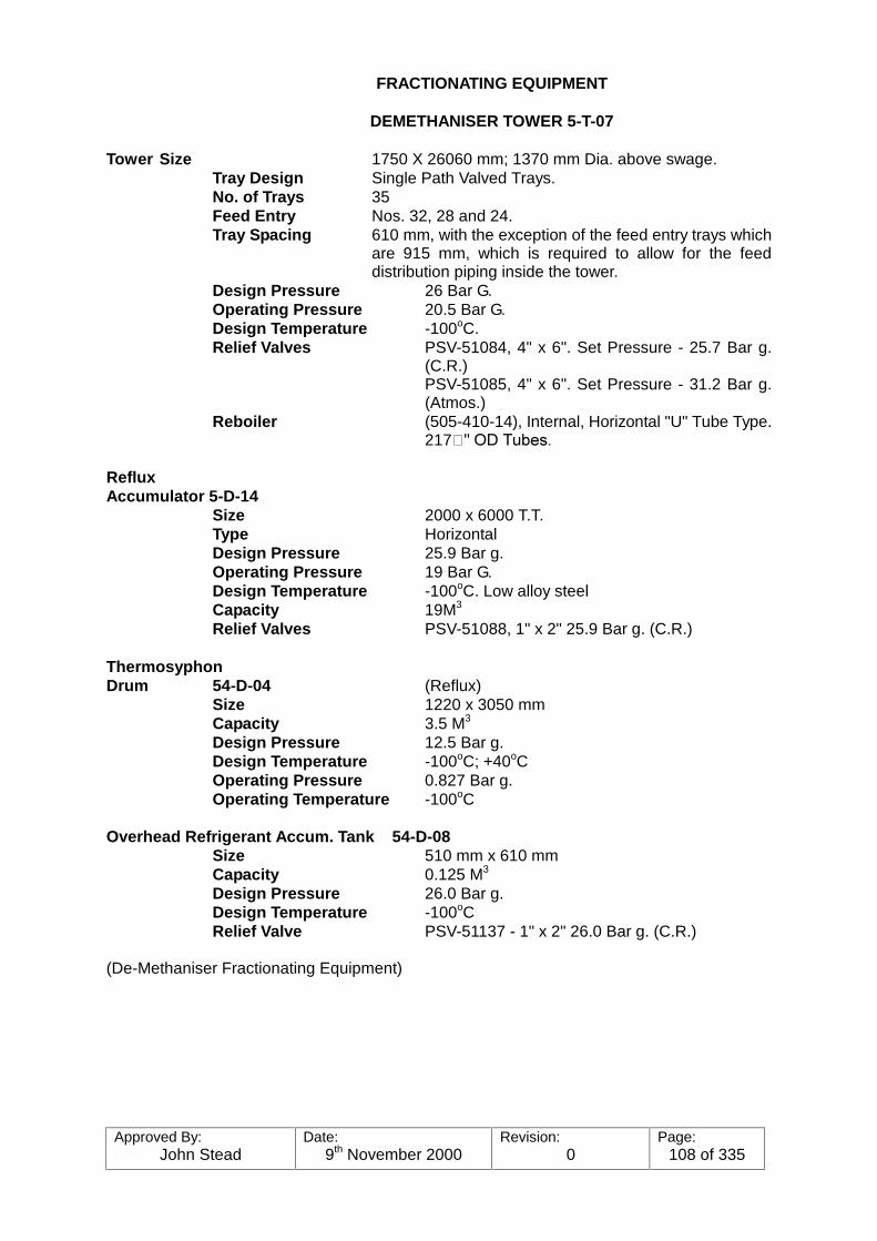
Approved By:John Stead
Date:9th November 2000
Revision:0
Page:108 of 335
FRACTIONATING EQUIPMENT
DEMETHANISER TOWER 5-T-07
Tower Size 1750 X 26060 mm; 1370 mm Dia. above swage.Tray Design Single Path Valved Trays.No. of Trays 35Feed Entry Nos. 32, 28 and 24.Tray Spacing 610 mm, with the exception of the feed entry trays which
are 915 mm, which is required to allow for the feeddistribution piping inside the tower.
Design Pressure 26 Bar G.Operating Pressure 20.5 Bar G.Design Temperature -100oC.Relief Valves PSV-51084, 4" x 6". Set Pressure - 25.7 Bar g.
(C.R.)PSV-51085, 4" x 6". Set Pressure - 31.2 Bar g.(Atmos.)
Reboiler (505-410-14), Internal, Horizontal "U" Tube Type.217���2'�7XEHV�
RefluxAccumulator 5-D-14
Size 2000 x 6000 T.T.Type HorizontalDesign Pressure 25.9 Bar g.Operating Pressure 19 Bar G.Design Temperature -100oC. Low alloy steelCapacity 19M3
Relief Valves PSV-51088, 1" x 2" 25.9 Bar g. (C.R.)
ThermosyphonDrum 54-D-04 (Reflux)
Size 1220 x 3050 mmCapacity 3.5 M3
Design Pressure 12.5 Bar g.Design Temperature -100oC; +40oCOperating Pressure 0.827 Bar g.Operating Temperature -100oC
Overhead Refrigerant Accum. Tank 54-D-08Size 510 mm x 610 mmCapacity 0.125 M3
Design Pressure 26.0 Bar g.Design Temperature -100oCRelief Valve PSV-51137 - 1" x 2" 26.0 Bar g. (C.R.)
(De-Methaniser Fractionating Equipment)
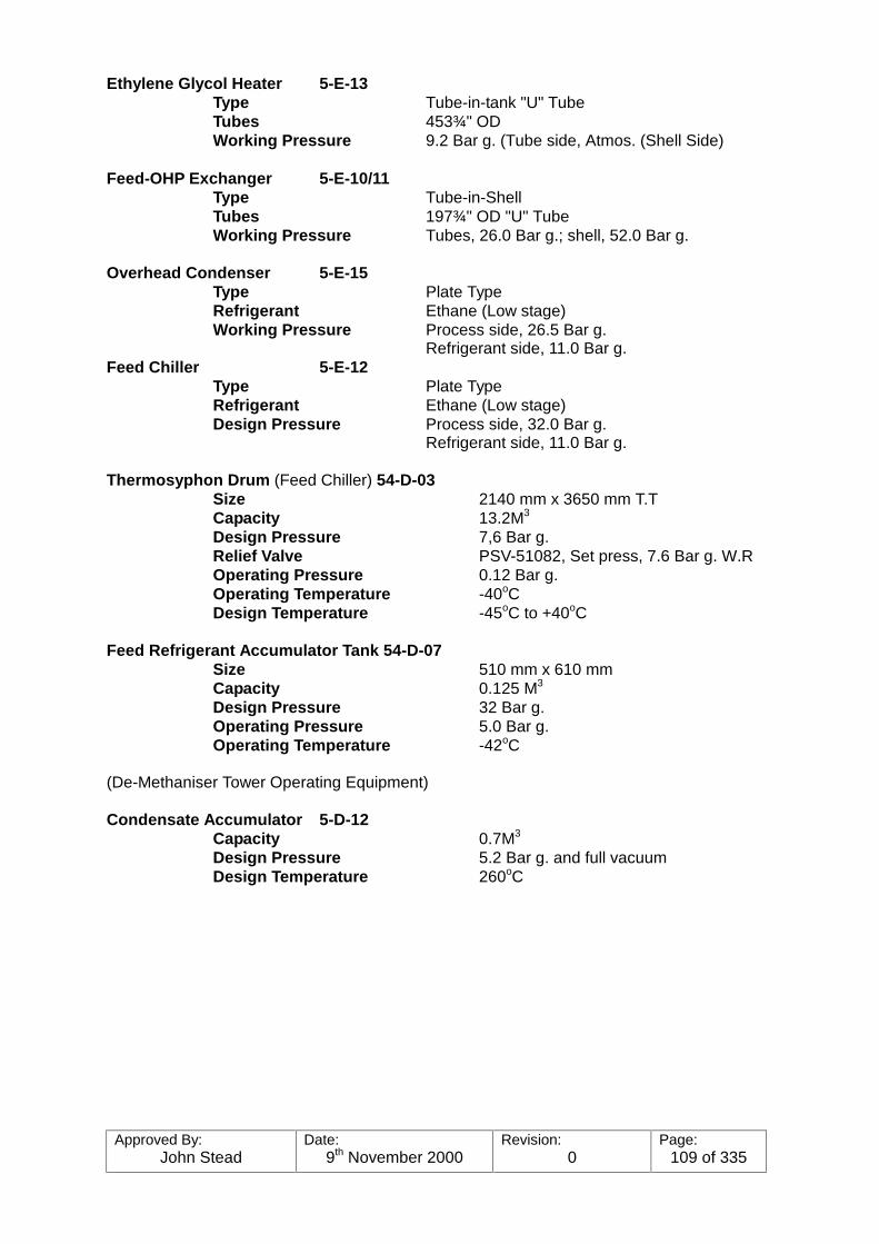
Approved By:John Stead
Date:9th November 2000
Revision:0
Page:109 of 335
Ethylene Glycol Heater 5-E-13Type Tube-in-tank "U" TubeTubes 453¾" ODWorking Pressure 9.2 Bar g. (Tube side, Atmos. (Shell Side)
Feed-OHP Exchanger 5-E-10/11Type Tube-in-ShellTubes 197¾" OD "U" TubeWorking Pressure Tubes, 26.0 Bar g.; shell, 52.0 Bar g.
Overhead Condenser 5-E-15Type Plate TypeRefrigerant Ethane (Low stage)Working Pressure Process side, 26.5 Bar g.
Refrigerant side, 11.0 Bar g.Feed Chiller 5-E-12
Type Plate TypeRefrigerant Ethane (Low stage)Design Pressure Process side, 32.0 Bar g.
Refrigerant side, 11.0 Bar g.
Thermosyphon Drum (Feed Chiller) 54-D-03Size 2140 mm x 3650 mm T.TCapacity 13.2M3
Design Pressure 7,6 Bar g.Relief Valve PSV-51082, Set press, 7.6 Bar g. W.ROperating Pressure 0.12 Bar g.Operating Temperature -40oCDesign Temperature -45oC to +40oC
Feed Refrigerant Accumulator Tank 54-D-07Size 510 mm x 610 mmCapacity 0.125 M3
Design Pressure 32 Bar g.Operating Pressure 5.0 Bar g.Operating Temperature -42oC
(De-Methaniser Tower Operating Equipment)
Condensate Accumulator 5-D-12Capacity 0.7M3
Design Pressure 5.2 Bar g. and full vacuumDesign Temperature 260oC

Approved By:John Stead
Date:9th November 2000
Revision:0
Page:110 of 335
PUMPS/COMPRESSORS
DEMETHANISER 5-T-07
SIZESERVICE NO
. SUCT. DISCH.
MAKEand
TYPE
PUMPSPEED-
RPM
SUCTIONPRESSURE
BAR-G
DISCHARGEPRESSURE
BAR-G
DIFFHEADBAR-G
MINFLOW
MAXFLOW
M3/hr
DRIVE(H.P)
DE-METHANISERREFLUX5-P-13/14
Bottoms Pump5-P-11/12
ETHYLENEGLYCOL PUMP5-P-9/10
CondensatePump5-P-7/8
2
2
2
2
3"
8"
4"
2"
2"
4"
3"
1"
DAVIDBROWNBINGHAM (Cent).
Ing.Rand.Cent.
Ing.Rand.Cent.
Ing.Rand.Cent.
2960
2950
2950
2900
19
20.6
0.3
2.0
23
25
2.76
6.1
4
4.4
2.46
4.1
12.5
23
9
1.5
34
120
65
4.6
20
50
15
4
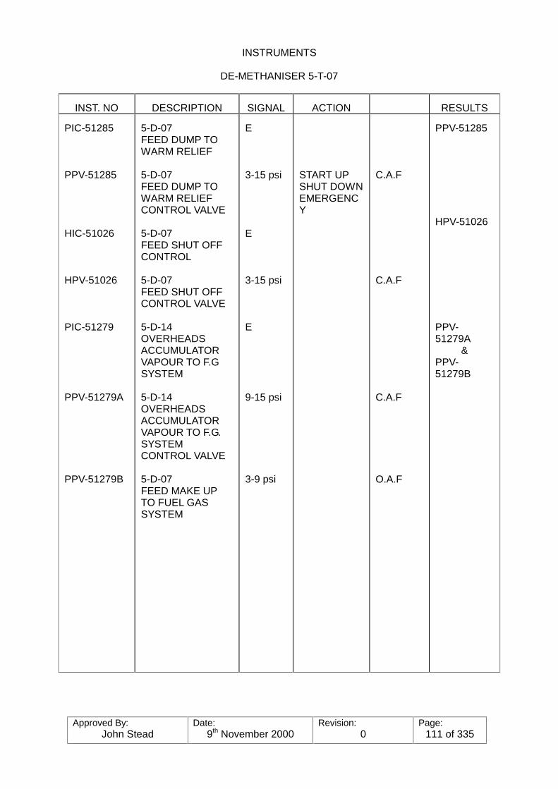
Approved By:John Stead
Date:9th November 2000
Revision:0
Page:111 of 335
INSTRUMENTS
DE-METHANISER 5-T-07
INST. NO DESCRIPTION SIGNAL ACTION RESULTS
PIC-51285
PPV-51285
HIC-51026
HPV-51026
PIC-51279
PPV-51279A
PPV-51279B
5-D-07FEED DUMP TOWARM RELIEF
5-D-07FEED DUMP TOWARM RELIEFCONTROL VALVE
5-D-07FEED SHUT OFFCONTROL
5-D-07FEED SHUT OFFCONTROL VALVE
5-D-14OVERHEADSACCUMULATORVAPOUR TO F.GSYSTEM
5-D-14OVERHEADSACCUMULATORVAPOUR TO F.G.SYSTEMCONTROL VALVE
5-D-07FEED MAKE UPTO FUEL GASSYSTEM
E
3-15 psi
E
3-15 psi
E
9-15 psi
3-9 psi
START UPSHUT DOWNEMERGENCY
C.A.F
C.A.F
C.A.F
O.A.F
PPV-51285
HPV-51026
PPV-51279A
&PPV-51279B

Approved By:John Stead
Date:9th November 2000
Revision:0
Page:112 of 335
INSTRUMENTS
DE-METHANISER 5-T-07
INST NO. DESCRIPTION SIGNAL ACTION Air Failure RESULTS
HIG-51067
HPV-51067
PIC-51307
PPV-51307
TIC-51265
TPV-51265
5-D-07OVERHEADSACCUMULATORVAPOUR EX
5-D-07OVERHEADSACCUMULATORVAPOUR EX
5-D-14OVERHEADSACCUMULATORPRESSCONTROL
5-D-14OVERHEADSACCUMULATORPRESSCONTROL VALVE
5-D-07FEED EXITCHILLER BOX5-E-12
54-D-03THERMOSYPHON DRUM VAPOUREXIT CONTROLVALVE
3-15 psi
E
3-15 psi
E
3-15 psi
C.A.F
C.A.F
O.A.F
HPV-51067
PPV-51307
TPV-51265

Approved By:John Stead
Date:9th November 2000
Revision:0
Page:113 of 335

Approved By:John Stead
Date:9th November 2000
Revision:0
Page:114 of 335
INSTRUMENTS
DE-METHANISER 5-T-07
INST NO. DESCRIPTION SIGNAL ACTION Air Failure RESULTS
LIC-51198
LPV-51198
HNS-51080
HPV-51080
PIC-51555
PPV-51555
TIC-51270 } }
FIC-51094 }
54-D-03THERMOSYPHON DRUM LEVELCONTROL
54-D-03THERMOSYPHON DRUM LEVELCONTROL VALVE
PROPANEREFRIGERANTTO 54-D-03
PROPANEREFRIGERANTTO 54-D-03 SHUTOFF CONTROLVALVE
54-D-07REFRIGEACCUMULATIONTANK PRESSCONTROL
54-D-07REFRIGEACCUMULATIONTANK PRESSCONTROL VALVE
5-E-13GLYCOLVAPOURISERTEMP CONTROL5-E-13GLYCOLVAPOURISER
E
3-15 psi
E
3-15 psi
PROCESS
3-15 psi
E
E
O.A.F
C.A.F
LPV-51198
HPV-51080
PPV-51555
FIC-51094
FPV-51094
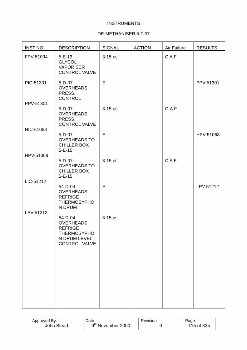
Approved By:John Stead
Date:9th November 2000
Revision:0
Page:115 of 335
INSTRUMENTS
DE-METHANISER 5-T-07
INST NO. DESCRIPTION SIGNAL ACTION Air Failure RESULTS
FPV-51094
PIC-51301
PPV-51301
HIC-51068
HPV-51068
LIC-51212
LPV-51212
5-E-13GLYCOLVAPORISERCONTROL VALVE
5-D-07OVERHEADSPRESS.CONTROL
5-D-07OVERHEADSPRESS.CONTROL VALVE
5-D-07OVERHEADS TOCHILLER BOX5-E-15
5-D-07OVERHEADS TOCHILLER BOX5-E-15
54-D-04OVERHEADSREFRIGETHERMOSYPHON DRUM
54-D-04OVERHEADSREFRIGETHERMOSYPHON DRUM LEVELCONTROL VALVE
3-15 psi
E
3-15 psi
E
3-15 psi
E
3-15 psi
C.A.F
O.A.F
C.A.F
PPV-51301
HPV-51068
LPV-51212
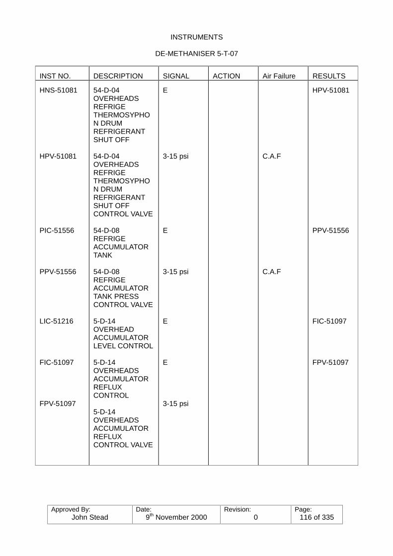
Approved By:John Stead
Date:9th November 2000
Revision:0
Page:116 of 335
INSTRUMENTS
DE-METHANISER 5-T-07
INST NO. DESCRIPTION SIGNAL ACTION Air Failure RESULTS
HNS-51081
HPV-51081
PIC-51556
PPV-51556
LIC-51216
FIC-51097
FPV-51097
54-D-04OVERHEADSREFRIGETHERMOSYPHON DRUMREFRIGERANTSHUT OFF
54-D-04OVERHEADSREFRIGETHERMOSYPHON DRUMREFRIGERANTSHUT OFFCONTROL VALVE
54-D-08REFRIGEACCUMULATORTANK
54-D-08REFRIGEACCUMULATORTANK PRESSCONTROL VALVE
5-D-14OVERHEADACCUMULATORLEVEL CONTROL
5-D-14OVERHEADSACCUMULATORREFLUXCONTROL
5-D-14OVERHEADSACCUMULATORREFLUXCONTROL VALVE
E
3-15 psi
E
3-15 psi
E
E
3-15 psi
C.A.F
C.A.F
HPV-51081
PPV-51556
FIC-51097
FPV-51097

Approved By:John Stead
Date:9th November 2000
Revision:0
Page:117 of 335
INSTRUMENTS
DE-METHANISER 5-T-07
INST NO. DESCRIPTION SIGNAL ACTION Air Failure RESULTS
LIC-51208
FIC-51096
FPV-51095
TIC-51272(4th TRAY)
TIC-510-96
FPV-51096
HIC-51027
HPV-51027
5-T-07BOTTOMS LEVELCONTROL
5-T-07GLYCOL TOCOLUMNREBOILER5-E-14
5-T-07GLYCOL TOCOLUMNREBOILER5-E-14CONTROL VALVE
5-T-07TEM. CONTROL
5-T-07BOTTOMS TOPRODUCTCHILLING
5-T-07BOTTOMS TOPRODUCTCHILLINGCONTROL VALVE
5-T-07BOTTOMS TOETHANE DUMPCONTROL VALVE
5-T-07BOTTOMS TOETHANE DUMPVESSEL
E
E
3-15 psi
E
E
3-15 psi
E
3-15 psi
C.A.F
C.A.F
C.A.F
FIC-51096
FPV-51095
FIC-51095
HPV-51027

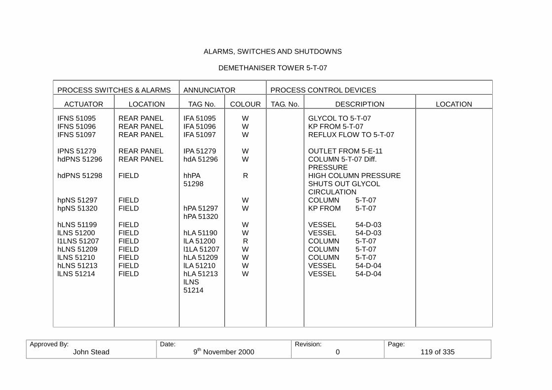
Approved By:John Stead
Date:9th November 2000
Revision:0
Page:119 of 335
ALARMS, SWITCHES AND SHUTDOWNS
DEMETHANISER TOWER 5-T-07
PROCESS SWITCHES & ALARMS ANNUNCIATOR PROCESS CONTROL DEVICES
ACTUATOR LOCATION TAG No. COLOUR TAG. No. DESCRIPTION LOCATION
IFNS 51095IFNS 51096IFNS 51097
IPNS 51279hdPNS 51296
hdPNS 51298
hpNS 51297hpNS 51320
hLNS 51199lLNS 51200l1LNS 51207hLNS 51209lLNS 51210hLNS 51213lLNS 51214
REAR PANELREAR PANELREAR PANEL
REAR PANELREAR PANEL
FIELD
FIELDFIELD
FIELDFIELDFIELDFIELDFIELDFIELDFIELD
IFA 51095IFA 51096IFA 51097
IPA 51279hdA 51296
hhPA51298
hPA 51297hPA 51320
hLA 51190lLA 51200l1LA 51207hLA 51209lLA 51210hLA 51213lLNS51214
WWW
WW
R
WW
WWRWWWW
GLYCOL TO 5-T-07KP FROM 5-T-07REFLUX FLOW TO 5-T-07
OUTLET FROM 5-E-11COLUMN 5-T-07 Diff.PRESSUREHIGH COLUMN PRESSURESHUTS OUT GLYCOLCIRCULATIONCOLUMN 5-T-07KP FROM 5-T-07
VESSEL 54-D-03VESSEL 54-D-03COLUMN 5-T-07COLUMN 5-T-07COLUMN 5-T-07VESSEL 54-D-04VESSEL 54-D-04
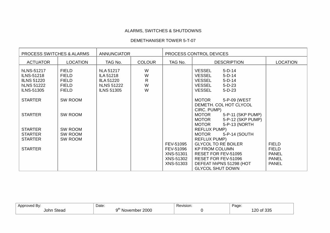
Approved By:John Stead
Date:9th November 2000
Revision:0
Page:120 of 335
ALARMS, SWITCHES & SHUTDOWNS
DEMETHANISER TOWER 5-T-07
PROCESS SWITCHES & ALARMS ANNUNCIATOR PROCESS CONTROL DEVICES
ACTUATOR LOCATION TAG No. COLOUR TAG No. DESCRIPTION LOCATION
hLNS-51217lLNS-51218llLNS 51220hLNS 51222lLNS-51305
STARTER
STARTER
STARTERSTARTERSTARTER
STARTER
FIELDFIELDFIELDFIELDFIELD
SW ROOM
SW ROOM
SW ROOMSW ROOMSW ROOM
hLA 51217lLA 51218llLA 51220hLNS 51222lLNS 51305
WWRWW
FEV-51095FEV-51096XNS-51301XNS-51302XNS-51303
VESSEL 5-D-14VESSEL 5-D-14VESSEL 5-D-14VESSEL 5-D-23VESSEL 5-D-23
MOTOR 5-P-09 (WESTDEMETH. COL HOT CLYCOLCIRC. PUMP)MOTOR 5-P-11 (SKP PUMP)MOTOR 5-P-12 (SKP PUMP)MOTOR 5-P-13 (NORTHREFLUX PUMP)MOTOR 5-P-14 (SOUTHREFLUX PUMP)GLYCOL TO RE BOILERKP FROM COLUMNRESET FOR FEV-51095RESET FOR FEV-51096DEFEAT hhPNS 51298 (HOTGLYCOL SHUT DOWN
FIELDFIELDPANELPANELPANEL
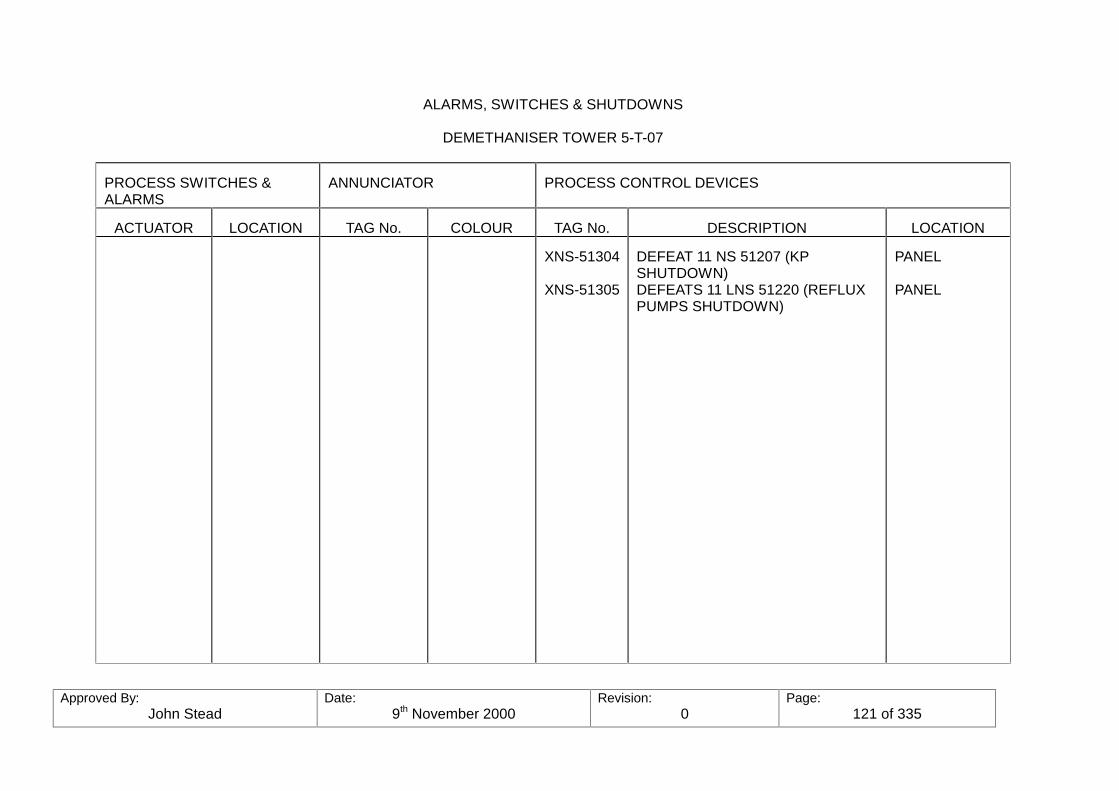
Approved By:John Stead
Date:9th November 2000
Revision:0
Page:121 of 335
ALARMS, SWITCHES & SHUTDOWNS
DEMETHANISER TOWER 5-T-07
PROCESS SWITCHES &ALARMS
ANNUNCIATOR PROCESS CONTROL DEVICES
ACTUATOR LOCATION TAG No. COLOUR TAG No. DESCRIPTION LOCATION
XNS-51304
XNS-51305
DEFEAT 11 NS 51207 (KPSHUTDOWN)DEFEATS 11 LNS 51220 (REFLUXPUMPS SHUTDOWN)
PANEL
PANEL

Approved By:John Stead
Date:9th November 2000
Revision:0
Page:122 of 335
PRESSURE SAFETY VALVES
DEMETHANISER COL. 5-T-07
VALVE No. LOCATION/DESCRIPTION
SETPRESS
TEMP. CAP. SIZE MATERIAL RELIEVESTO:
PSV-51080
PSV-51081
PSV-51082
PSV-51083
PSV-51078
PSV-51084
PSV-51085
PSV-51086
5-E-10/11DEMETHANISERFEEDEXCHANGERSTUBE SIDE
54-D-03DE-METHANISERFEEDREFRIGERANTTHERMOSYPHONDRYM VAPOUREXIT
54-D-03DE-METHANISERFEEDREFRIGERANTTHERMOSYPHONDRUM
5-E-12DE-METHANISERFEED CHILLER
54-D-07DE-METHANISERFEEDREFRIGERANTACCUMULATORTANK
5-T-07OVERHEADSVAPOUR LINE
5-T-07OVERHEADSVAPOUR LINE
54-D-04DE-METHANISERREFRIGERANTOVERHEADSTHERMOSYPHONDRUM
26.0 BAR G
7.6 BAR G
7.6 BAR G
32.0 BAR G
32.0 BAR G
25.7 BAR G
31.2 BAR G
12.5 BAR G
¾" x 1"
4" x 6"
1½" x 3"
1" x 2"
1" x 2"
4" x 6"
4" x 6"
1" x 2"
FUEL GAS(METHANE)
PROPANE
PROPANE
METHANE&
ETHANE
METHANE
METHANE
ETHANE
ATMOS.
WARMRELIEF
WARMRELIEF
COLDRELIEF
WARMRELIEF
COLDRELIEF
ATMOS.
COLDRELIEF

Approved By:John Stead
Date:9th November 2000
Revision:0
Page:123 of 335
PRESSURE SAFETY VALVES
DEMETHANISER COL. 5-T-07
VALVE No. LOCATION/DESCRIPTION
SET PRESS TEMP. CAP. SIZE MATERIAL RELIEVESTO:
PSV-51087
PSV-51088
PSV-51089
PSV-51137
PSV-51138
PSV-51139
PSV-51140
PSV-51141
PSV-51147
5-E-15DE-METHANISEROVERHEADCHILLER
5-D-14DE-METHANISEROVERHEADREFLUXACCUMULATOR
5-P-11/12D-METHANISERBOTTOMSPRODUCT LINE
54-D-08DE-METHANISEROVERHEADACCUMULATORTANK
5-P-11DE-METHANISERCOLUMN K.P.PUMP
5-P-12
5-P-13DE-METHANISERCOLUMNREFLUX PUMP
5-P-14
DE-METHANISERREFLUX LINE3"551-L43-043EX-5-P-13/14
26.5 BAG G.
25.9 BAR G.
30.0 BAR G.
26.0 BAR G.
30.0 BAR G.
"
30.0 BAR G.
"
30.0 BAR G.
1" x 2"
1" x 2"
¾" x 1"
1" x 2"
¾" x 1"
"
¾" x 1"
"
¾" x 1"
METHANE
METHANE
ETHANE
METHANE&
ETHANE
ETHANE
"
METHANE
"
METHANE
COLDRELIEF
COLDRELIEF
ETHANEPROD.DUMP (REFRIGEFLARESYSTEM)COLDRELIEF
PUMPSUCTION
"
"
"
ATMOS.

Approved By:John Stead
Date:9th November 2000
Revision:0
Page:124 of 335
PRESSURE SAFETY VALVES
DE-ETHANISER COL. 5-T-07
VALVE No. LOCATION/DESCRIPTION
SET PRESS TEMP. CAP. SIZE MATERIAL RELIEVESTO:
PSV-51233
PSV-51234
PSV-51235
DE-METHANISERBOTTOMS PUMPRE-CIRCULATIONLINE 3"551-L64-077EX 5-P-11/12
DE-METHANISERBOTTOMS LINE 6"551-L64-002EX-5-P-11/12
DE-METHANISERCOLUMN REFLUXLINE 3"551-L43-014EX-5-P-13/14
30.0 BAR G.
30.0 BAR G.
30.0 BAR G.
¾" x 1"
¾" x 1"
¾" x 1"
ETHANE
ETHANE
METHANE
ATOMS
ATOMS
ATOMS
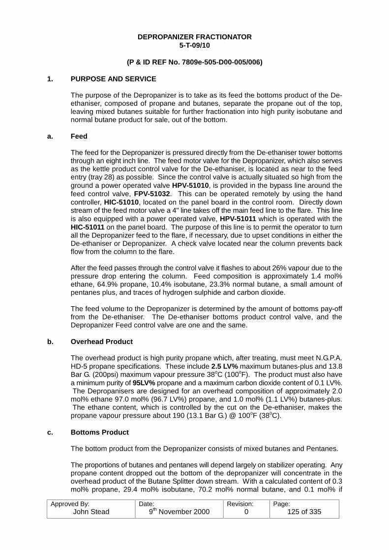
Approved By:John Stead
Date:9th November 2000
Revision:0
Page:125 of 335
DEPROPANIZER FRACTIONATOR5-T-09/10
(P & ID REF No. 7809e-505-D00-005/006)
1. PURPOSE AND SERVICE
The purpose of the Depropanizer is to take as its feed the bottoms product of the De-ethaniser, composed of propane and butanes, separate the propane out of the top,leaving mixed butanes suitable for further fractionation into high purity isobutane andnormal butane product for sale, out of the bottom.
a. Feed
The feed for the Depropanizer is pressured directly from the De-ethaniser tower bottomsthrough an eight inch line. The feed motor valve for the Depropanizer, which also servesas the kettle product control valve for the De-ethaniser, is located as near to the feedentry (tray 28) as possible. Since the control valve is actually situated so high from theground a power operated valve HPV-51010, is provided in the bypass line around thefeed control valve, FPV-51032. This can be operated remotely by using the handcontroller, HIC-51010, located on the panel board in the control room. Directly downstream of the feed motor valve a 4" line takes off the main feed line to the flare. This lineis also equipped with a power operated valve, HPV-51011 which is operated with theHIC-51011 on the panel board. The purpose of this line is to permit the operator to turnall the Depropanizer feed to the flare, if necessary, due to upset conditions in either theDe-ethaniser or Depropanizer. A check valve located near the column prevents backflow from the column to the flare.
After the feed passes through the control valve it flashes to about 26% vapour due to thepressure drop entering the column. Feed composition is approximately 1.4 mol%ethane, 64.9% propane, 10.4% isobutane, 23.3% normal butane, a small amount ofpentanes plus, and traces of hydrogen sulphide and carbon dioxide.
The feed volume to the Depropanizer is determined by the amount of bottoms pay-offfrom the De-ethaniser. The De-ethaniser bottoms product control valve, and theDepropanizer Feed control valve are one and the same.
b. Overhead Product
The overhead product is high purity propane which, after treating, must meet N.G.P.A.HD-5 propane specifications. These include 2.5 LV% maximum butanes-plus and 13.8Bar G. (200psi) maximum vapour pressure 38oC (100oF). The product must also havea minimum purity of 95LV% propane and a maximum carbon dioxide content of 0.1 LV%. The Depropanisers are designed for an overhead composition of approximately 2.0mol% ethane 97.0 mol% (96.7 LV%) propane, and 1.0 mol% (1.1 LV%) butanes-plus. The ethane content, which is controlled by the cut on the De-ethaniser, makes thepropane vapour pressure about 190 (13.1 Bar G.) @ 100oF (38oC).
c. Bottoms Product
The bottom product from the Depropanizer consists of mixed butanes and Pentanes.
The proportions of butanes and pentanes will depend largely on stabilizer operating. Anypropane content dropped out the bottom of the depropanizer will concentrate in theoverhead product of the Butane Splitter down stream. With a calculated content of 0.3mol% propane, 29.4 mol% isobutane, 70.2 mol% normal butane, and 0.1 mol% if

Approved By:John Stead
Date:9th November 2000
Revision:0
Page:126 of 335
pentanes-plus, the propane content in the Butane Splitter will concentrate to about 1.0mol% in the isobutane. The vapour pressure of the isobutane would well be within specsat 4.0 Bar G. (58 psi) @ 38oC. (100oF) at those conditions, but any higher percentage ofpropane allowed out the bottom would make it very difficult, or impossible, to come upwith isobutane at specification vapour pressure.
The Depropanisers are not likely to make a cut this good at all times, due to dynamicsurges and with the possibility of feed different than design. Since the primary obligationis to make specification propane overhead, the bottom product may contain excesspropane.
2. Separation
The key components of the separation are propane out of the top and isobutane andheavier out of the bottom. To keep butanes-plus below 2.5 LV% in the overhead productrequires a recovery of about 94% of the isobutane from the feed to the bottom of thecolumn. To reduce the propane content of the bottom product to 0.3%, which will enablethe Butane Splitter overhead product to make specs, requires a recovery of 99.8% of thepropane from the feed to the overhead. The system is designed for a high recovery witha 50 tray column and reflux-to-feed ratio of 0.9 mol/mol or 0.86 barrel/barrel.(0.86m3/m3/).
3. Process Equipment
The two Depropanizer are 2900mm (9’-5") in diameter by 34,620 mm (about 113 feet)in height. Each column is equipped with 50 valve trays, double cross flow, spaced at610mm (20") intervals, with the exception of the feed entry tray which is spaced at610mm (20") intervals, with the exception of the feed entry tray which is spaced at1220mm (48"). (This was necessary to provide the extra space between the trays for theinternal feed distributors). Valve trays were selected for their turn-down ability to 50% orless of design feed rates. As in the case of the De-ethaniser, in the event of low feedavailability, one Depropanizer can be out of service and the other operated at 25% orless of total design feed.
Two steam-heated U-tube reboilers side by side, in the bottom of the column are usedfor heat source. Each re-boiler contains 240 hair pin or U tube shaped, one inch tubesand are sized to vapourize about 82% of the liquid reaching the bottom of the tower. Theremainder is draw off as bottom product.
Condensate Pumps
Two condensate pumps are provided to pump the condensed steam from thecondensate accumulator to the condensate gathering system. One pump is for serviceand the other is for stand-by. They both are Ingersoll Rand centrifugal type pumps withrated maximum capacity of 22M3/hr (about 138 b/hr) and minimum flow of 3.3M3/hr,(about 20 B/hr). They are driven with 10hp, 415V. 3 phase 50 cycle electric motors at2900 rpm.
The condensate accumulator for the Depropanisers are horizontal tanks 760mm id x1525mm T.T. having a capacity of 0.7M3 each. (About 4.39 bbls). The level is controlledby a liquid level controller, LNC-51245, which operates control valve LPV-51245 (on No.1 Depropanizer). The condensate is pumped into the 4" low pressure condensate line4" 651-T21-517 back tot he condensate gathering system at the boiler house.
Power to drive the fans is provided by a 40 h.p., 415V 50 cycle motor each. Each set oftwo coils has two fans. Adjustable louvres are provided to aid in temp control across the
Approved By:John Stead
Date:9th November 2000
Revision:0
Page:127 of 335
coils, as well as the ability to shut down fans if necessary during cold weather.The condensed liquid leaves from each coil through a six inch lateral and is manifoldedinto a common 8" line, 8"-551-L40-368, where it then flows into the accumulator.
The Accumulator is a horizontal vessel (5-D-19) 2900 mm ID (9.5’) by 8700 mm (28.5’)long, with a rated capacity of 61M3 (about 383 bbls). It has a working pressure at 11.5Bar G. (028 psig) and design temperature of 60oC (140oF)/ -35oC, (-31oF).
In order to maintain a vapour space in the top of the accumulator and provide a workinglevel, some of the column overhead vapours is by-passed around the condenser througha 6 inch (6"-551-L40-367) line, and control valve PPV-51332 into the top of theaccumulator. This is also serves as a method of pressure maintenance on the vessel. The vessel has about seven minutes of surge time when running half full of liquid.
Reflux Pumps
The liquid is then pumped from the accumulator with the reflux pumps (one on line, oneon stand-by) back to the top of the column, with a side stream taking off the dischargeside as the overhead product. The pumps are centrifugal, 295M3/hr (1852.6 bbls/hr)capacity, 1460 rpm, made by Ingersoll-Rand. They are driven by 100 h.p. 415V 3 phase50 cycle motors. The reflux pumps return about 60% of the liquid as reflux to the top trayof the column and deliver the remainder as overhead product.
5. Control System
The feed to the De-propanizer is on flow control reset by the De-ethaniser’s DistillationColumn Controls (Computer) or by the De-ethaniser’s tray temperature controller. Asstated before, the De-propanizer’s feed motor valve and the De-ethaniser’s bottomsproduct motor valve are the same valve. Whatever the De-ethaniser pays off, the De-propanizer must feed, (or go to the flare).
Steam to the De-propanizer reboiler is flow control FPV-51101, reset by the liquid levelcontroller, IC-51223, located near the bottom of the tower. An increase in kettle level willadd steam to re-boil more up into the top of the column, thereby holding the level as set. Opposite reactions take place in case the level should drop.
Column Pressure is on back pressure control at the overhead vapour line. Controlvalve PPV-51330. located in the 14" vapour line is actuated by PIC-51330 which sensesthe pressure from pressure point PNT-51330 located on the overhead line upstream ofthe back pressure control valve, PPV-51330. The air fin fan louvres located above theoverhead condenser, 5-E-24, are on hand control, HIC-51030, and is the only control(aside from shutting down or starting fans, or coil pinching) provided for the refluxcondensing temperature. Normal Operating Pressure is 12.5 BAR.
Accumulator pressure is maintained by using a combination of two valves, 6" PPV-51332A and 10" PPV-51332B, both located in the overhead vapour piping upstream ofthe overhead condensers. A pressure controller, PIC-51332, which receives its signalfrom pressure point PNT-51332 located on the accumulator, will control the accumulatorpressure by opening up on the 6", PPV-51332A and pinching back on the 10" PPV-51332B, to force hot vapour off the overhead vapour line into the accumulator there-bymaintaining the set pressure of the PIC-51332. (This forces hot vapours around thecondenser directly to the accumulator through a separate line). Normal operatingpressure is 11.5 BAR.
External reflux rate is on flow control, FPV-51102, reset by the Distillation ColumnControl, or by straight rate of flow control if necessary.
Approved By:John Stead
Date:9th November 2000
Revision:0
Page:128 of 335
Overhead Product is controlled by the level in the accumulator. Accumulator LIC-51227re-sets FIC-51103 which of flow control if necessary.
Distillation Column Controls. The Distillation Column Control employs a computer toimplement feed forward and feed back control of the two De-propanizers. Before thiscan work, certain information must be fed into the computer, such as feed rate, reflux andoverhead temperatures and overhead composition. Bottom composition-which is veryimportant, is monitored or ratioed to overhead composition for control. Chromatagraphanalysers which are used for product analysis are "batch type" analysis, etc. As themixture passes through the "column" in the analysis, each component of the mixtureencounters a different resistance to travel, therefore each component will require adifferent length of time to travel through the column, and the components-lightest gasesfirst, etc.-will leave the columns separately. An electronic device at the exit of the columnmeasures the quantity of product leaving the column at a given time and this informationis relayed to the computer.
Four analysers are used to determine these compositions. Two are used on the De-propanizers overhead product liquid for control, and the other two used on the bottomproducts for monitoring and/or control. The overhead analyser should show iso-butaneto be about 0.4 mol% of the stream, and the bottom product analyser should showpropane to be about 0.3mol% the stream, or 1.0 to 15mol% of the iso-butane in thestream.
The computer reads and stores the results of the overhead product analysis along withthe column feed, reflux temp, and bottoms rate. This information is compared withprevious stored information in the computer both from previous process information, andpre-set operating limitations implemented by the operators of the P.O.C. The computerthen makes adjustments to the bottom flow rate and/or reflux flow rate to maintain thedesired column operating conditions to produce specification propane out the top, andspecification feed stock for the Butane Splitter downstream, out the bottom.
6. Alarms and Safety Features. The control valves throughout the De-propanizer systemsare designed to "fail safe" in case of loss of instrument power, air or electricity. Thecontrol valves will open or close in a pattern that blocks in feed, overhead and bottomstreams, shut off the steam to the re-boilers, allows the overhead vapour to flow throughthe con denser and liquid to be pumped back into the column if the reflux pump isoperable. Valve actions in case of instrument air failure are listed below:
Instrument Air Failure
Valve Service ActionPPV-51330 Col. back pressure OpenPPV-51332-A Accum. press mtcc. OpenPPV-51332-B Accum. press mtcc. ClosesFPV-51102 Reflux OpenFPV-51104 K.P. ClosesFPV-51103 OHP ClosesFPV-51101 Steam ClosesLPV-51231 Condensate OpensFPV-51104 Bottoms Product ClosesK.P. Cooler Air fin Louvres Open

Approved By:John Stead
Date:9th November 2000
Revision:0
Page:129 of 335
7. Operating Procedure
The following discussion is offered to illustrate certain actions to be considered in putting theprocess equipment into service, or shutting it down. It should be noted, however, that these aregeneral and that at times, special instructions pertaining to different types, or conditions of start-up or shut-downs may be issued.

Approved By:John Stead
Date:9th November 2000
Revision:0
Page:130 of 335
a. Start-up
Preparatory to start-up all utilities must be in service, (including hot and cold ventsystems, all drain system), instrumentation checked out and all rotating equipmenttested. Steam supply line should be warmed up and drained of all liquid to the controlvalve, and the condensate system lined up and ready to go. One, or both De-ethanizersmust be operating to furnish suitable feed for the De-propanizer with the feed switchedto the flare until such time as the De-propanizer can be started.
It should also be pointed out that on this particular write-up, the number oneDepropanizer will be the one described, and assume that number two De-propanizer isnot running.
To start up a De-propanizer for the first time or any time after it has been down andpurged of hydrocarbon, it is necessary to purge the system of all air before it can bestarted. The normal method would be to purge with feed, but the Teesside equipmentis provided with piped in purge gas which can be tied into the bottom of the volume withtemporary swing pipe, or nitrogen may be used. The time element will play a definite partin which method is used, either purge gas, nitrogen or feed, but in this case let usassume nitrogen gas is to be used.
After close inspection has been made for blinds that may have been overlooked,equipment properly re-fitted, and all drains and bleeders closed, blind flanges removedfrom the 3" bleeder valve, and the bleeders opened on the overhead vapour line and 2"blind plate off the top of the reflux accumulator we are ready to start.
Notify utilities and all personnel in the area, and see that all chain gates, or road barriersare up to prevent vehicle entry to the affected area, or area down wind.
After nitrogen has been tried in, slowly crack open the purge valve and admit nitrogento the bottom of the tower through the entry valve provided. After a good rate has beenestablished in the tower crack open 3" vent (blind plate already removed) off theoverhead vapour line to let air out of the system. Open the bleeders on all gaugeglasses and control barrels on the bottom of the column, and start checking for gas. Thenitrogen will displace the air out the top through the overhead vapour line and towardsthe overhead condensers. (Have all coils blocked in but one).
As the nitrogen displaces the air in the column it will also be backing out the reflux line. Since there is a check valve in the reflux pump discharge line it will be necessary topurge the reflux line from two directions - Block in the reflux control valve block valve, onthe pumps side - open the bleeder between the reflux motor valve and the block valve,and open the reflux motor valve with the control - this will allow the air to be pushed outthe reflux line from the column down through the bleeder on the reflux motor valve (theother half is purged later, as shown below).
Keep checking bleeder for air %. Block bleeder of when the air has been displaced.
When nitrogen is detected on the 3" bleeder on the overhead vapour line start checkingfor nitrogen exiting from the bleeder on the coil in the overhead condenser that is open. When nitrogen is detected on the outlet of the coil, start blocking in this coil and openingthe next coil and bleeder next (closing bleeders as coils are purged). Continue thisprocess on all coils.
During this time, air has been displaced out the 3" bleeder on top of the accumulator, sosomeone should be watching this also.

Approved By:John Stead
Date:9th November 2000
Revision:0
Page:131 of 335
When all the coils are purged it won’t be long until signs will be showing up from thebleeder on the accumulator - (by this time, have the accumulator gauge columns,glasses, and control barrels bleeders open). When nitrogen is detected form thesebleeders, open the reflux pump suction valve, open the bleeder on the pump case andcheck for gas here. With the reflux pump discharge valve still blocked, go to the refluxcontrol valve, block in the isolating valve on the column side (leaving bleeder open) andopen the isolating valve on the pump side-when the air has been displaced at the pumpcasing bleeder, open the pump discharge valve and purge the remaining section of refluxline out through the bleeder on the control valve piping. When no air is detected here,block in the purge gas to the column, and then block in there flux motor valve bleeder,along with any more that may still be open.
If purge nitrogen, or purge gas is not elected to be used as the purging agent then thesame procedure can be used by using feed, with the following exceptions: First establisha level in the bottom of the column with feed by cracking open the feed motor valve by-pass valve HPV-51011 with the control on the panel board and letting feed in this wayaround the feed motor valve. The same precautions, and method of watching for vapourout the vents can be applied. There should be little steam cracked through the reboilerto prevent freezing the condensed steam in the tubes. A good way to insure this is tohave the bleeder open to the slab on the condensate run-down lines to the condensateaccumulator to keep the reboiler warm. Use the by-pass line around the steam motorvalve during this time - cracked.
All during the time that feed has been admitted to the column it will have beenvaporising, so close watch on the bleeders must be had at all times. shut the feed outwhen a level has been established in the bottom-crack a little more steam through thereboiler and keep checking vents-exactly in the same order as the other method.
When all the air is out, the column is ready to start.
b. Starting the Column
Due to the control arrangements on the De-ethaniser tower bottom line, (which is thefeed line to the De-propanizer tower), in order to have the De-ethaniser on spec andready to go to the De-propanizer, it would have been switched to the flare-which takesoff the De-ethaniser bottoms line down stream of the De-ethaniser K.P. control valve-andsince the pressure on he De-propanizer at this time is nil, the main isolating valve on theDe-propanizer column must be closed to prevent filling up to the column with feed beforeit was on spec, or ready to receive. This means that someone must climb the tower tothe feed entry level and manually operate the feed entry valve to the column, whenready. This applies to the initial purge step- (Method No. 2) and initial start up step.
After manually opening the feed valve at a fairly low rate to start with, (with part of thefeed still going to flare through the 4" flare valve, HPV-51011), admit feed again until agood level is established in the column bottom.
When a good level is established, increase the steam to the column and start buildingup pressure and temperature- (all coils will be open @ this step due to purging). Checklevel in condensate pot and start the condensate pump, if not already started due tocondensate build-up form warm-up stage. Have the column back pressure control eitheron manual, or on by-pass during this initial period to allow some heat to pass through theoverhead condensers for gradual warm-up. This should also prevent any excess"knocking" as the hot vapour pass through cold equipment.

Approved By:John Stead
Date:9th November 2000
Revision:0
Page:132 of 335
After the coils have had a little time to warm up, then begin starting sir fin fans. Continueincreasing steam, either on "manual" or, by-pass (By pass preferred) and letting thepressure and heat build up until near operating levels, then switch the back pressurecontrols on automatic, this also applies to the accumulator pressure-which should havebeen coming up with the column due to the back pressure motor valve by-pass beingopen allowing a constant flow of hot vapour out through the system.
During this time so far, some of the vapour has been condensing and dropping out in theaccumulator-when a pumping level been established in the accumulator, open throughthe reflux line (with overhead product line still blocked off) control valve and start refluxpump. (Be sure the pump case has been properly primed with liquid, and un-gassed). Start reflux at a low rate at first, as it will tend to pull the level down in the vessel-keepat low rate, increasing only as liquid level in accumulator will allow. The sooner, however,that the proper reflux rate is achieved, the sooner the column will be on line.
Continue increasing reflux and feed with the controls-until desired are evident- the openthe product lines to the flare until on spec. When the propane out the overhead is onspec, the propane treater, and out of the flare. When the bottom is on spec, switch tothe Butane Treater, and out of the flare.
Initially the column bottom product flow controller may be put on tray temperature controlif desired. When conditions are reasonably well lined out, the sampling system shouldbe started and the analysers put into service. When functioning properly the DistillationColumn Control may be put into service.
c. Shut Down
When it is necessary to completely shut down the column and purge the system forrepair work the following procedure may be used:Inform the Boiler House and all others involved. Take the distillation column control outof service. Switch the feed to the flare by opening the 4" vent to flare line valve HPV-51011 with HIC-51011. (The check valve in the feed line will prevent any back flow fromthe tower to go to the flare but the feed line must be blocked in at the column). Open thebottoms product to the flare by opening the 6" valve HPV-51028 with HIC-51028. Acheck valve will prevent back flow. Open the overhead product to flare by operating 3"HPV-51037 valve with HIC-51073. A check valve is installed here also to prevent backflow to the flare-from the product line down-stream. Shut off the supply, and condensatepump. Block in condensate. Continue to reflux the column as long as there is anythingleft to pump in the accumulator.
During this time, the pressure on the column and accumulator will continue to drop. Lower pointer on column back pressure controller to keep the overhead vapour motorvalve open to let out vapour from the column as long as possible. The accumulator backpressure motor valves will position themselves in the maximum pressure make-upsituation, which will prevent the vapour from flushing the coils, so pull the accumulatorback pressure pointer down to force the remaining column overhead vapour through thecondensing coils, flushing the majority of liquid into the accumulator. As the columnempties up, shut down the air in fan to minimize any mor condensation so that thevapour may be passed on out the accumulator 2" line to relief (shut down reflux pumpwhen it gasses off); this will minimize the amount of liquid settling out in the vessel toweather off. As the column pressure comes down most of the lighter ends will flash off,but more than likely a residual amount of heavies will accumulate in the bottom which willhave to be drained out along with any in the accumulator, to the enclosed drain system. (Close watch on blow egg is necessary here). To aid in the final draining, it would behelpful to hook the purge gas back into the column, and pressure out the remaining liquidto drain system. This would also help flush the underground drain line and blow egg ofliquid.
Approved By:John Stead
Date:9th November 2000
Revision:0
Page:133 of 335
After all liquid and pressure has been blown out through the various product lines, anddrain, block in the overhead product line at the overhead product control valve, thebottom product at the tower and at the bottom product control valve.
Note:If the Depropanizer is to be down an extended length of time the corresponding De-ethaniser should also be shut down to prevent excessive loss of product to the flare.
After all pressure is off, and the tower is drained up it can be vapour freed by steamingwith 3.5 bar g. steam.
d. Refluxing the column
At times, due to temporary trouble with the De-ethaniser, for instance, and the feed to theDe-propanizer is not on specs, or due to low incoming feed it is possible that the columnwill have to be refluxed rather than completely shut down.
If the reason is due to complete loss of feed flow meter will go to zero and cause theDistillation Column control to shut in the bottom product, and reduce the reflux to theminimum stop. The accumulator liquid level control would shut in the overhead productflow when the level in the accumulator reached the cut-off point on the control. Thecolumn would then be on total reflux. If, instead, the feed is not lost, but switched to theflare, the feed signal still passes through the feed meter, so the Distillation ColumnControl completely. In either case, the operator should physically shut in the overhead,and bottom products to prevent leakage down stream. The column bottom liquid levelwill continue to keep the right amount of steam in the reboiler for equilibrium.
When ready to go back on stream, ease the feed back into the column, and put back onfeed forwards control or, in the case of temperature control, simple open the productstreams, and re-adjust the column trim as necessary.
8. Power Failure.
In a total failure all motors will go down. The electronic instruments will operate off thebatteries and the emergency generator will furnish power to keep the batteries charged,but the process will be down. The equipment usually will start pressuring up due to lossof reflux over top of the tower and the effect of latent heat in the bottom. The steam willautomatically shut off, but if it does not, block it in anyway. The worst thing about powerfailure other than the initial shock of it is knowing the duration of it. In any case, theequipment is down, and must be treated as a total shut down and act accordingly. If thefeed is still coming in (which it probably won’t be) switch it to the flare. BLOCK in theproduct stream to conserve levels as much as possible in the tower bottom andaccumulator.
When the power is restored, start up the cooling fans and reflux pump as quickly aspossible, then put the feed back in (if available) and switch the product streams back out(either to flare, or storage depending on duration of power outage, and the columnconditions).
Another type of power failure is the "skip" type-in this case not all equipment is lost. Usually it is caused by a "dip" in power, but whatever the cause the affect can bedangerous. Try immediately to re-start the downed motor-it may need to be re-set, or insome cases not. Get them started, however, as quickly as possible-as speed countshere. If the reflux pump, for instance, goes down and nothing else, try to get it or thespare pump back on line at once.
Approved By:John Stead
Date:9th November 2000
Revision:0
Page:134 of 335
If it is impossible to get it re-started, shut down the column. A condensate pump,however, can be down for one reason or another, and not require the column to be down-as the condensate can be "ditched" to the drain temporarily.
It is very difficult to write down the exact actions to take during a power failure due to thedifferent situations it can cause, but more than likely it will be either a total failure of yoursection, a total Plant failure, or a "spot" type as mentioned above.
9. Instrument Air Failure
An instrument air failure will result in the loss of the air supply between the control outputtransmitter to the control valve diaphragms, rendering the valves inoperative. In thiscase the control valves will "fail" either open, or closed. As outlined before, in paragraph8, the control valves were placed in their respective location with this idea in mind so thatif the air is lost they except for attempting to use by-passes and go on complete handcontrol. This is almost impossible with the amount of controls in the unit.
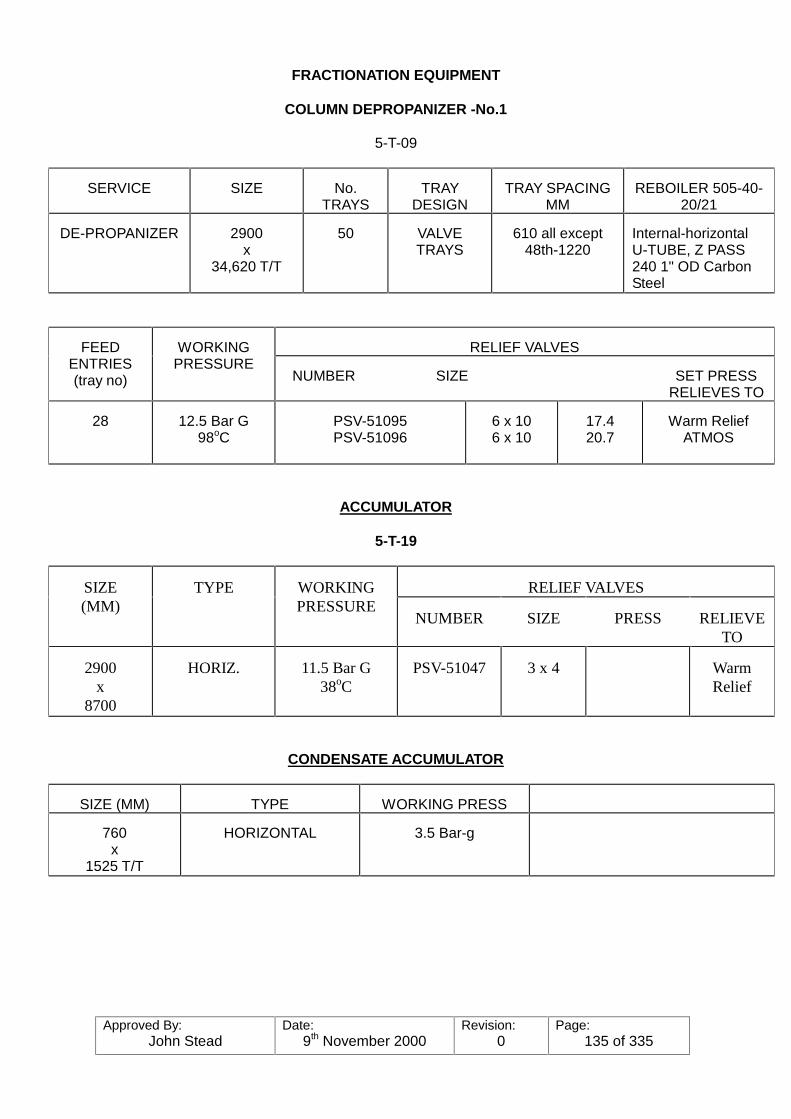
Approved By:John Stead
Date:9th November 2000
Revision:0
Page:135 of 335
FRACTIONATION EQUIPMENT
COLUMN DEPROPANIZER -No.1
5-T-09
SERVICE SIZE No.TRAYS
TRAYDESIGN
TRAY SPACINGMM
REBOILER 505-40-20/21
DE-PROPANIZER 2900x
34,620 T/T
50 VALVETRAYS
610 all except48th-1220
Internal-horizontalU-TUBE, Z PASS240 1" OD CarbonSteel
RELIEF VALVESFEEDENTRIES(tray no)
WORKINGPRESSURE
NUMBER SIZE SET PRESSRELIEVES TO
28 12.5 Bar G98oC
PSV-51095PSV-51096
6 x 106 x 10
17.420.7
Warm ReliefATMOS
ACCUMULATOR
5-T-19
RELIEF VALVESSIZE(MM)
TYPE WORKINGPRESSURE
NUMBER SIZE PRESS RELIEVETO
2900x
8700
HORIZ. 11.5 Bar G38oC
PSV-51047 3 x 4 WarmRelief
CONDENSATE ACCUMULATOR
SIZE (MM) TYPE WORKING PRESS
760x
1525 T/T
HORIZONTAL 3.5 Bar-g
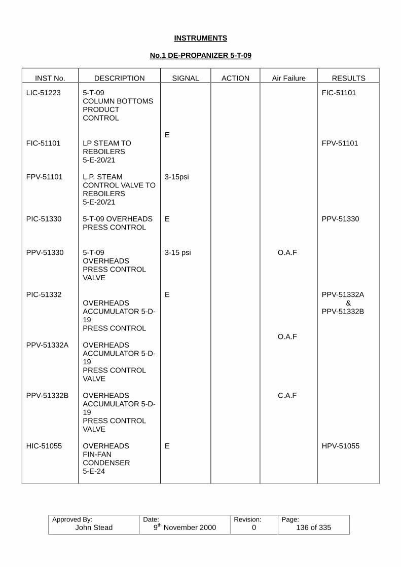
Approved By:John Stead
Date:9th November 2000
Revision:0
Page:136 of 335
INSTRUMENTS
No.1 DE-PROPANIZER 5-T-09
INST No. DESCRIPTION SIGNAL ACTION Air Failure RESULTS
LIC-51223
FIC-51101
FPV-51101
PIC-51330
PPV-51330
PIC-51332
PPV-51332A
PPV-51332B
HIC-51055
5-T-09COLUMN BOTTOMSPRODUCTCONTROL
LP STEAM TOREBOILERS5-E-20/21
L.P. STEAMCONTROL VALVE TOREBOILERS5-E-20/21
5-T-09 OVERHEADSPRESS CONTROL
5-T-09OVERHEADSPRESS CONTROLVALVE
OVERHEADSACCUMULATOR 5-D-19PRESS CONTROL
OVERHEADSACCUMULATOR 5-D-19PRESS CONTROLVALVE
OVERHEADSACCUMULATOR 5-D-19PRESS CONTROLVALVE
OVERHEADSFIN-FANCONDENSER5-E-24
E
3-15psi
E
3-15 psi
E
E
O.A.F
O.A.F
C.A.F
FIC-51101
FPV-51101
PPV-51330
PPV-51332A&
PPV-51332B
HPV-51055
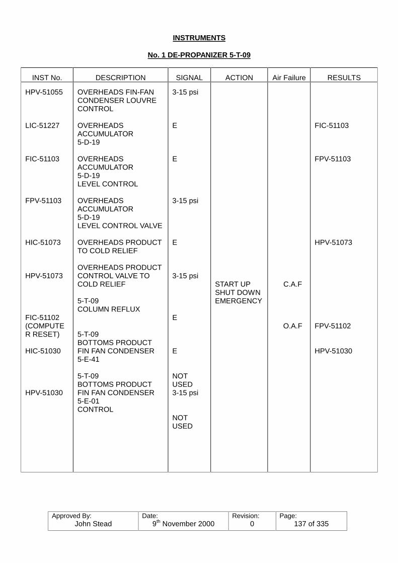
Approved By:John Stead
Date:9th November 2000
Revision:0
Page:137 of 335
INSTRUMENTS
No. 1 DE-PROPANIZER 5-T-09
INST No. DESCRIPTION SIGNAL ACTION Air Failure RESULTS
HPV-51055
LIC-51227
FIC-51103
FPV-51103
HIC-51073
HPV-51073
FIC-51102(COMPUTER RESET)
HIC-51030
HPV-51030
OVERHEADS FIN-FANCONDENSER LOUVRECONTROL
OVERHEADSACCUMULATOR5-D-19
OVERHEADSACCUMULATOR5-D-19LEVEL CONTROL
OVERHEADSACCUMULATOR5-D-19LEVEL CONTROL VALVE
OVERHEADS PRODUCTTO COLD RELIEF
OVERHEADS PRODUCTCONTROL VALVE TOCOLD RELIEF
5-T-09COLUMN REFLUX
5-T-09BOTTOMS PRODUCTFIN FAN CONDENSER5-E-41
5-T-09BOTTOMS PRODUCTFIN FAN CONDENSER5-E-01CONTROL
3-15 psi
E
E
3-15 psi
E
3-15 psi
E
E
NOTUSED3-15 psi
NOTUSED
START UPSHUT DOWNEMERGENCY
C.A.F
O.A.F
FIC-51103
FPV-51103
HPV-51073
FPV-51102
HPV-51030
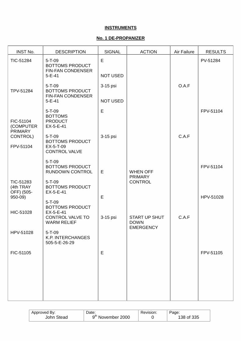
Approved By:John Stead
Date:9th November 2000
Revision:0
Page:138 of 335
INSTRUMENTS
No. 1 DE-PROPANIZER
INST No. DESCRIPTION SIGNAL ACTION Air Failure RESULTS
TIC-51284
TPV-51284
FIC-51104(COMPUTERPRIMARYCONTROL)
FPV-51104
TIC-51283(4th TRAYOFF) (505-950-09)
HIC-51028
HPV-51028
FIC-51105
5-T-09BOTTOMS PRODUCTFIN-FAN CONDENSER5-E-41
5-T-09BOTTOMS PRODUCTFIN-FAN CONDENSER5-E-41
5-T-09BOTTOMSPRODUCTEX-5-E-41
5-T-09BOTTOMS PRODUCTEX-5-T-09CONTROL VALVE
5-T-09BOTTOMS PRODUCTRUNDOWN CONTROL
5-T-09BOTTOMS PRODUCTEX-5-E-41
5-T-09BOTTOMS PRODUCTEX-5-E-41CONTROL VALVE TOWARM RELIEF
5-T-09K.P. INTERCHANGES505-5-E-26-29
E
NOT USED
3-15 psi
NOT USED
E
3-15 psi
E
E
3-15 psi
E
WHEN OFFPRIMARYCONTROL
START UP SHUTDOWNEMERGENCY
O.A.F
C.A.F
C.A.F
PV-51284
FPV-51104
FPV-51104
HPV-51028
FPV-51105
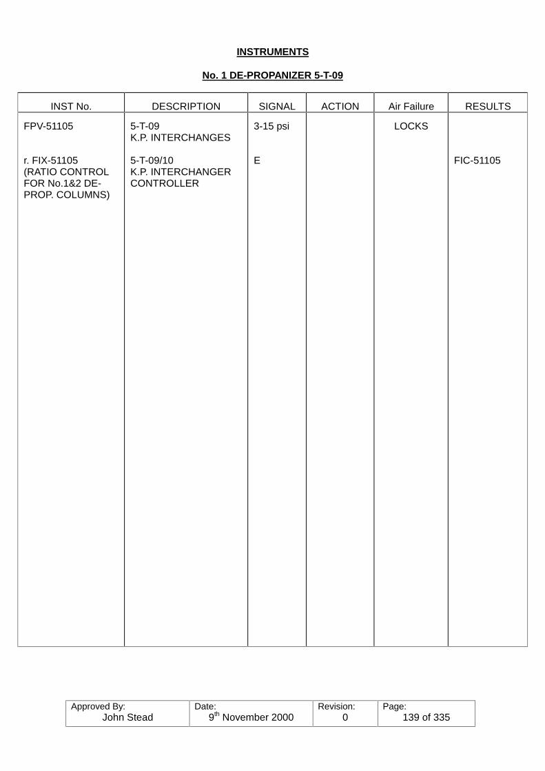
Approved By:John Stead
Date:9th November 2000
Revision:0
Page:139 of 335
INSTRUMENTS
No. 1 DE-PROPANIZER 5-T-09
INST No. DESCRIPTION SIGNAL ACTION Air Failure RESULTS
FPV-51105
r. FIX-51105(RATIO CONTROLFOR No.1&2 DE-PROP. COLUMNS)
5-T-09K.P. INTERCHANGES
5-T-09/10K.P. INTERCHANGERCONTROLLER
3-15 psi
E
LOCKS
FIC-51105

Approved By:John Stead
Date:9th November 2000
Revision:0
Page:140 of 335
PRESSURE SAFETY VALVES
No. 1 DE-PROPANIZER 5-T-09
VALVE NO. LOCATION/DESCRIPTION
SETPRESS.
TEMP. CAP SIZE MATERIAL RELIVE TO:
PSV-51095
PSV-51096
PSV-51097
PSV-51098
PSV-51099
5-T-09COLUMN OVERHEADSVAPOUR LINE
5-T-09COLUMN OVERHEADSVAPOUR LINE
5-D-19DEPROPANIZERREFLUXACCUMULATOR
5-E-26 TO 29DEPROPANIZER K.P.INTERCHANGES TUBESIDE
5-E-26 TO 29DEPROPANIZER K.P.INTERCHANGESSHELL SIDE
17.4 BAR-G
20.7 BAR-G
18.0 BAR-G
17.9 BAR-G
NOT USED
17.9 BAR-G
NOT USED
6" x 10"
6" x 10
3" x 4"
1" x 2"
1½" x 2"
PROPANE
PROPANE
PROPANE
BUTANES(DRIED)
BUTANES(WET)
WARM RELIEF
ATMOS.
WARM RELIEF
ATMOS.
WARM RELIEF
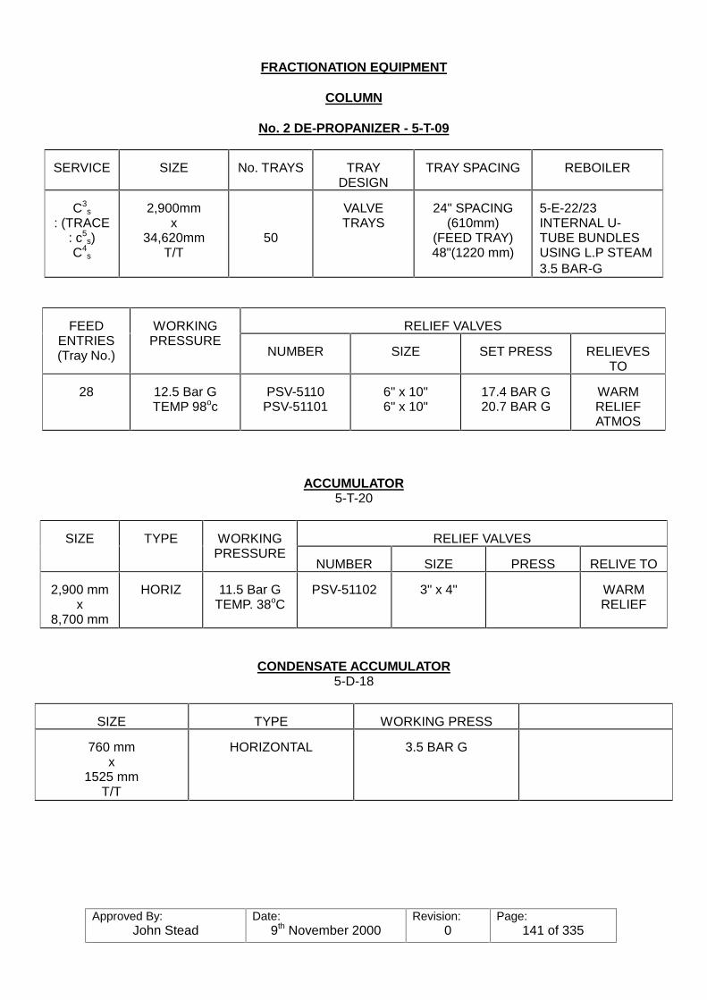
Approved By:John Stead
Date:9th November 2000
Revision:0
Page:141 of 335
FRACTIONATION EQUIPMENT
COLUMN
No. 2 DE-PROPANIZER - 5-T-09
SERVICE SIZE No. TRAYS TRAYDESIGN
TRAY SPACING REBOILER
C3s
: (TRACE: c5
s)C4
s
2,900mmx
34,620mmT/T
50
VALVETRAYS
24" SPACING(610mm)
(FEED TRAY)48"(1220 mm)
5-E-22/23INTERNAL U-TUBE BUNDLESUSING L.P STEAM3.5 BAR-G
RELIEF VALVESFEEDENTRIES(Tray No.)
WORKINGPRESSURE
NUMBER SIZE SET PRESS RELIEVESTO
28 12.5 Bar GTEMP 98oc
PSV-5110PSV-51101
6" x 10"6" x 10"
17.4 BAR G20.7 BAR G
WARMRELIEFATMOS
ACCUMULATOR5-T-20
RELIEF VALVESSIZE TYPE WORKINGPRESSURE
NUMBER SIZE PRESS RELIVE TO
2,900 mmx
8,700 mm
HORIZ 11.5 Bar GTEMP. 38oC
PSV-51102 3" x 4" WARMRELIEF
CONDENSATE ACCUMULATOR5-D-18
SIZE TYPE WORKING PRESS
760 mmx
1525 mmT/T
HORIZONTAL 3.5 BAR G
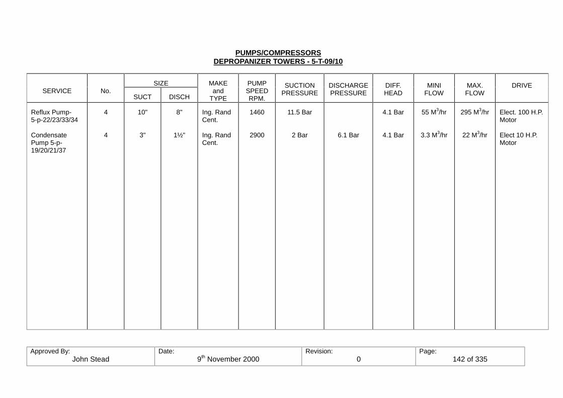
Approved By:John Stead
Date:9th November 2000
Revision:0
Page:142 of 335
PUMPS/COMPRESSORSDEPROPANIZER TOWERS - 5-T-09/10
SIZESERVICE No.
SUCT DISCH
MAKEand
TYPE
PUMPSPEEDRPM.
SUCTIONPRESSURE
DISCHARGEPRESSURE
DIFF.HEAD
MINIFLOW
MAX.FLOW
DRIVE
Reflux Pump-5-p-22/23/33/34
CondensatePump 5-p-19/20/21/37
4
4
10"
3"
8"
1½"
Ing. RandCent.
Ing. RandCent.
1460
2900
11.5 Bar
2 Bar 6.1 Bar
4.1 Bar
4.1 Bar
55 M3/hr
3.3 M3/hr
295 M3/hr
22 M3/hr
Elect. 100 H.P.Motor
Elect 10 H.P.Motor
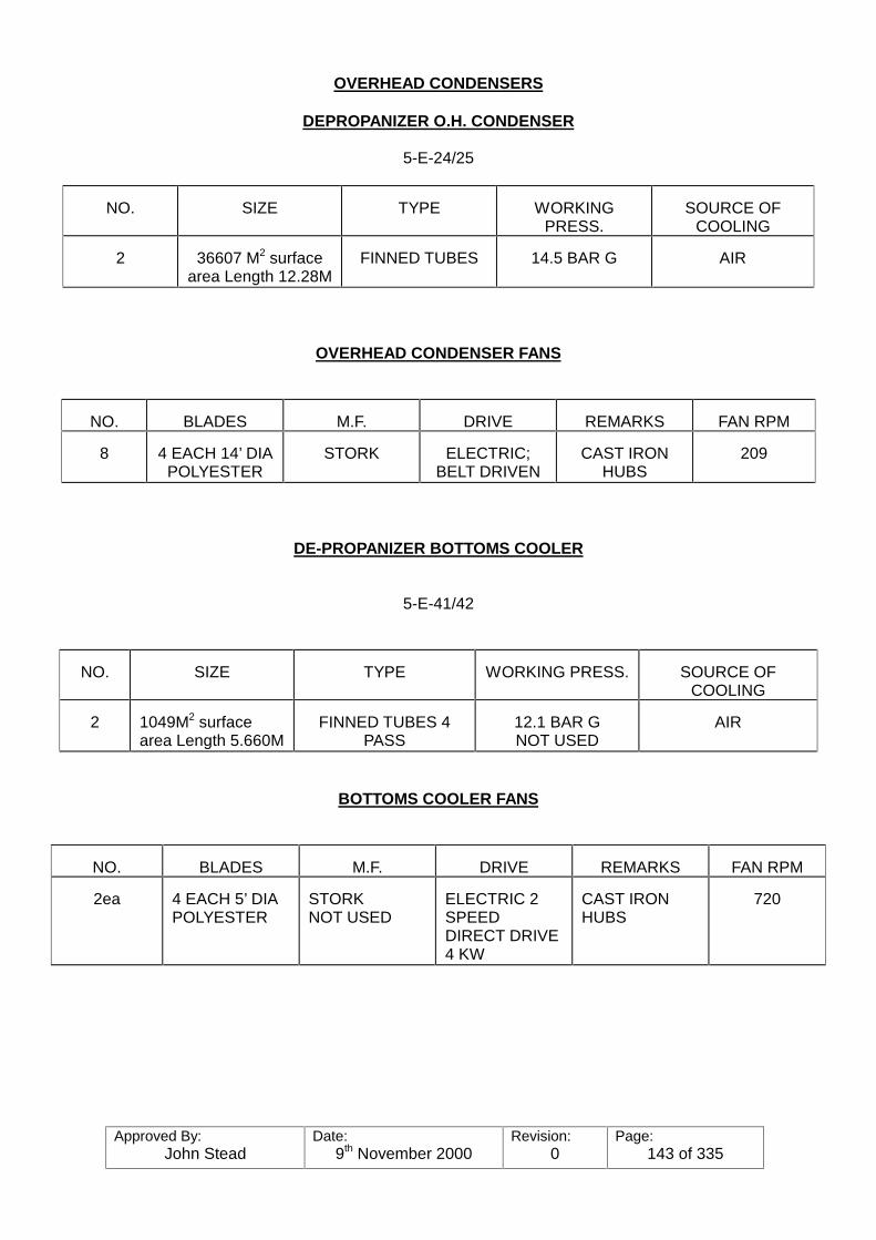
Approved By:John Stead
Date:9th November 2000
Revision:0
Page:143 of 335
OVERHEAD CONDENSERS
DEPROPANIZER O.H. CONDENSER
5-E-24/25
NO. SIZE TYPE WORKINGPRESS.
SOURCE OFCOOLING
2 36607 M2 surfacearea Length 12.28M
FINNED TUBES 14.5 BAR G AIR
OVERHEAD CONDENSER FANS
NO. BLADES M.F. DRIVE REMARKS FAN RPM
8 4 EACH 14’ DIAPOLYESTER
STORK ELECTRIC;BELT DRIVEN
CAST IRONHUBS
209
DE-PROPANIZER BOTTOMS COOLER
5-E-41/42
NO. SIZE TYPE WORKING PRESS. SOURCE OFCOOLING
2 1049M2 surfacearea Length 5.660M
FINNED TUBES 4PASS
12.1 BAR GNOT USED
AIR
BOTTOMS COOLER FANS
NO. BLADES M.F. DRIVE REMARKS FAN RPM
2ea 4 EACH 5’ DIAPOLYESTER
STORKNOT USED
ELECTRIC 2SPEEDDIRECT DRIVE4 KW
CAST IRONHUBS
720
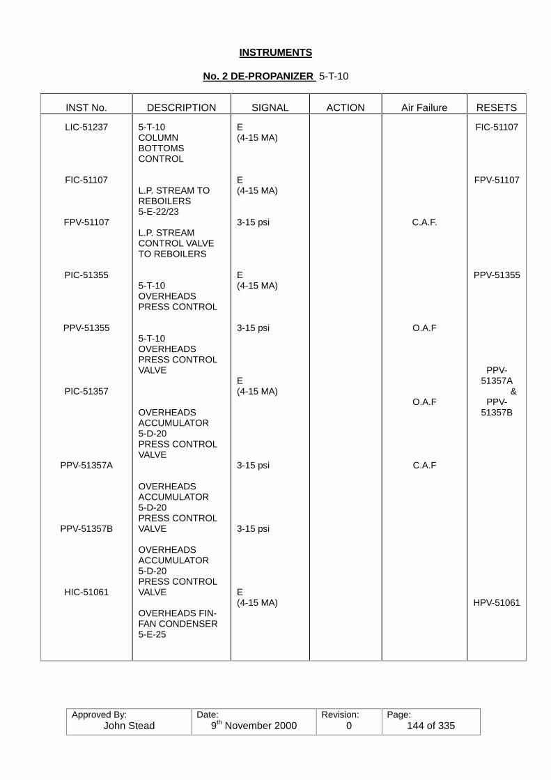
Approved By:John Stead
Date:9th November 2000
Revision:0
Page:144 of 335
INSTRUMENTS
No. 2 DE-PROPANIZER 5-T-10
INST No. DESCRIPTION SIGNAL ACTION Air Failure RESETS
LIC-51237
FIC-51107
FPV-51107
PIC-51355
PPV-51355
PIC-51357
PPV-51357A
PPV-51357B
HIC-51061
5-T-10COLUMNBOTTOMSCONTROL
L.P. STREAM TOREBOILERS5-E-22/23
L.P. STREAMCONTROL VALVETO REBOILERS
5-T-10OVERHEADSPRESS CONTROL
5-T-10OVERHEADSPRESS CONTROLVALVE
OVERHEADSACCUMULATOR5-D-20PRESS CONTROLVALVE
OVERHEADSACCUMULATOR5-D-20PRESS CONTROLVALVE
OVERHEADSACCUMULATOR5-D-20PRESS CONTROLVALVE
OVERHEADS FIN-FAN CONDENSER5-E-25
E(4-15 MA)
E(4-15 MA)
3-15 psi
E(4-15 MA)
3-15 psi
E(4-15 MA)
3-15 psi
3-15 psi
E(4-15 MA)
C.A.F.
O.A.F
O.A.F
C.A.F
FIC-51107
FPV-51107
PPV-51355
PPV-51357A
&PPV-
51357B
HPV-51061

Approved By:John Stead
Date:9th November 2000
Revision:0
Page:145 of 335
INSTRUMENTS
No. 2 DE-PROPANIZER - 5-T-10
INST. NO DESCRIPTION SIGNAL ACTION Air Failure RESETS
HPV-51061
FIC-51108
FPV-51108
LIC-51241
FIC-51109
FPV-51109
HIC-51074
HPV-51074
HIC-51031
OVERHEADS FIN-FANCONDENSER5-E-25LOUVRECONTROL
5-T-10COLUMN REFLUX
5-T-10COLUMN REFLUXCONTROL VALVE
OVERHEADSACCUMULATOR5-D-20LEVEL CONTROL
OVERHEADSACCUMULATOR5-D-20LEVEL CONTROL
OVERHEADSACCUMULATOR5-D-20LEVEL CONTROLVALVE
OVERHEADSPRODUCE TOCOLD RELIEF
OVERHEADSPRODUCTS TOCOLD RELIEFCONTROL VALVE
5-T-10BOTTOMSPRODUCTCONDENSER5-E-42LOUVRECONTROL
3-15 psi
E(4-15 MA)
3-15 psi
E4-15 MA)
E(4-15 MA)
3-15 psi
E(4-15 MA)
3-15 psi
E(4-15 MA)
NOT USED
O.A.F
C.A.F
C.A.F
FPV-51108
FIC-51109
FPV-51109
HPV-51074
HPV-51031
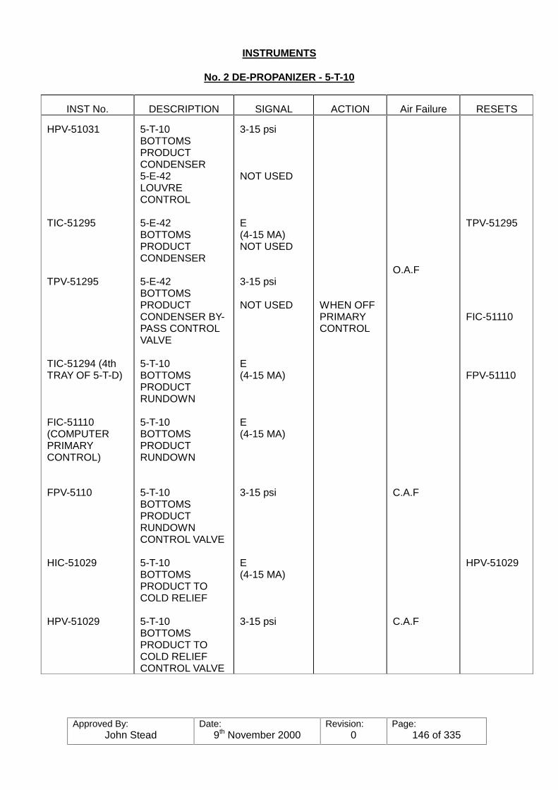
Approved By:John Stead
Date:9th November 2000
Revision:0
Page:146 of 335
INSTRUMENTS
No. 2 DE-PROPANIZER - 5-T-10
INST No. DESCRIPTION SIGNAL ACTION Air Failure RESETS
HPV-51031
TIC-51295
TPV-51295
TIC-51294 (4thTRAY OF 5-T-D)
FIC-51110(COMPUTERPRIMARYCONTROL)
FPV-5110
HIC-51029
HPV-51029
5-T-10BOTTOMSPRODUCTCONDENSER5-E-42LOUVRECONTROL
5-E-42BOTTOMSPRODUCTCONDENSER
5-E-42BOTTOMSPRODUCTCONDENSER BY-PASS CONTROLVALVE
5-T-10BOTTOMSPRODUCTRUNDOWN
5-T-10BOTTOMSPRODUCTRUNDOWN
5-T-10BOTTOMSPRODUCTRUNDOWNCONTROL VALVE
5-T-10BOTTOMSPRODUCT TOCOLD RELIEF
5-T-10BOTTOMSPRODUCT TOCOLD RELIEFCONTROL VALVE
3-15 psi
NOT USED
E(4-15 MA)NOT USED
3-15 psi
NOT USED
E(4-15 MA)
E(4-15 MA)
3-15 psi
E(4-15 MA)
3-15 psi
WHEN OFFPRIMARYCONTROL
O.A.F
C.A.F
C.A.F
TPV-51295
FIC-51110
FPV-51110
HPV-51029
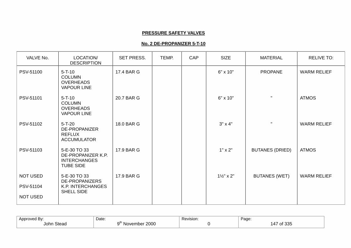
Approved By:John Stead
Date:9th November 2000
Revision:0
Page:147 of 335
PRESSURE SAFETY VALVES
No. 2 DE-PROPANIZER 5-T-10
VALVE No. LOCATION/DESCRIPTION
SET PRESS. TEMP. CAP SIZE MATERIAL RELIVE TO:
PSV-51100
PSV-51101
PSV-51102
PSV-51103
NOT USED
PSV-51104
NOT USED
5-T-10COLUMNOVERHEADSVAPOUR LINE
5-T-10COLUMNOVERHEADSVAPOUR LINE
5-T-20DE-PROPANIZERREFLUXACCUMULATOR
5-E-30 TO 33DE-PROPANIZER K.P.INTERCHANGESTUBE SIDE
5-E-30 TO 33DE-PROPANIZERSK.P. INTERCHANGESSHELL SIDE
17.4 BAR G
20.7 BAR G
18.0 BAR G
17.9 BAR G
17.9 BAR G
6" x 10"
6" x 10"
3" x 4"
1" x 2"
1½" x 2"
PROPANE
"
"
BUTANES (DRIED)
BUTANES (WET)
WARM RELIEF
ATMOS
WARM RELIEF
ATMOS
WARM RELIEF

Approved By:John Stead
Date:9th November 2000
Revision:0
Page:148 of 335
6. BUTANE TREATER/DEHYDRATOR TREATING SYSTEM:53-T-33/34/35/36/37P & ID Ref: 7809-519-D00-005
a. The Butane treater receives mixed as its feed from the bottom product of thedepropanizer Fractionating towers, and removes the water and sulphur compounds toprovide a suitable product for refrigerated storage and sales.
Specifications for the treated butanes are: 2 ppm maximum, and volatile sulphurcompounds 15 grains/100 cu’. The water specifications are required to prevent freezeups when the temperatures are reduced to permit storage in atmospheric pressuresrefrigerated storage tanks, and the sulphur must be reduced so that it can meet salesspecifications.
The systems required for this operation include the following equipment:-
(1) Two Butane Dehydrator Feed Pumps (53-p-09/10)(2) Five Butane Treating Towers (53-T-33/34/35/36/37)(3) One Butane Dehydrator Regeneration Separator (53-D-38)(4) One Butane Dehydrator Regeneration Cooler (53-E-12)
(One of the Propane Treater Coolers is connected as a common spare).(5) Two Butane Dehydrator Regeneration Separator Pumps (53-P-11/12)(6) Two sets of Regeneration Gas Heaters (53-E-15/16/19/20/21/22)
The system begins with the Dehydrator Feed Surge Tank and ends, for the liquid stream,at the inlet to the Depropanizer Kettle product heat exchanger. The regeneration gassystem ends with the back pressure controller on the line to the feed system.
Flow Description The wet liquid mixed butanes flow from the bottom of the depropanizertowers through the shell side of the DEC-3 kettle product heat exchangers 53-E-30/31/32/33 and out through a 6" line into an air fin cooler (5-E-41) where it is cooled toaround 38oC. It is then routed through a 4" line through the Depropanizer bottomsproduct control valve where it joins up with the No. 2 Depropanizer bottoms product. Thecombined streams enter a 6" line from this point on into the Butane Treater Surge Tank.
The liquid from the surge tank is then pumped tot he treaters on line where it enters thebottom, flowing upwards through the beds where it makes contact with the ALUMINAballs and MOL SIEVE fill material. Moisture and sulphur is removed in this process byabsorption in the beds. The liquid then flows out of the top of treaters into a commonoutlet header where it is routed through the tube side of the Depropanizer kettle productheat exchangers described above and on out to become the feed for the butane splittercolumn. A continuous sulphur analyser (AR 51017) has been installed on the commonoutlet header, which will sound an alarm if the sulphur content of the butanes becomeshigh or if the analyser fails. Since water is more strongly absorbed by the desiccant thatsulphur compounds, the sulphur will break through long before the water. Consequentlyonly sulphur content is monitored to determine the effectiveness of treating anddehydration.
Regeneration As the Butane is being treated in the Treating Tower the desiccant isgradually being saturated with water and sulphur and will reach a point where it will nolonger function. It must then be taken off the line re-generated.
Regeneration is process of "cleaning up" the beds enabling them to be used again. Thisprocess is accomplished by taking a stream off of the High Pressure Fuel gas header(Demethaniser overhead gas), heating it to 316oC with superheated steam in thevaporisers and passing it through the beds from the top, and out the bottom. Theelevated Regeneration Gas temperature vaporises the moisture and sulphur from the
Approved By:John Stead
Date:9th November 2000
Revision:0
Page:149 of 335
mol-sieves and sweeps them on out with the gas. The gas, along with the moisture andsulphur is then routed through an air fin condenser (53-E-12) where the temperature islowered to around 38oC (100oF) before entering the Regeneration Separator (53-D-28).The moisture is condensed, along with the heavier hydrocarbons and drops out to thebottom of the vessel where the water is drawn off (manually) and the liquid hydrocarbonsare pumped back to the feed tank. The Regeneration Separator is automatically pumpedback to the beds now on line. Tank (53-D-32) where it enters with the fresh feed comingin to the beds now on line. The feed tank has a Liquid level control that resets the feedto the Butane Splitter Tower which should maintain a level at all times, but is equippedwith a low level shut down switch in case of problems upstream of the Depropanizer,which will shut down the feed pump.
After the heating step has been completed the Bed must be cooled before putting it backin service. This is accomplished be taking a side stream of the liquid feed and pumpingit back through the Bed in an UPWARD flow. Part of this liquid will flash, or vapourizewhen it first hits the hot bed but will eventually cool down, condense in the condensingair fin condenser (53-E-12) and drop out in the bottom of the Regeneration Separator(like the heating step) and then be pumped back to the Feed Tank (53-D-32).
The Dehydrator Regeneration Pumps provide enough pressure to prevent any "flashing"of liquids in the Beds, which can damage the desiccant, as well as adequate pressureto get cooling Butane into the Regeneration Separator against the Regeneration Gaspressure even at times when the Feed Tank pressure is low. In order to properly feedthese pumps, the Feed Surge Tank (53-D-32) is provided at the Pump’s suction. Thistank has about 12 minutes of residence time when half full.
The Regeneration Separator (53-D-38) is made large enough to hold all the liquid fromone Treater/Dehydrator Tower and still provide for gas/liquid separation. This isdesigned this way so that the liquid in a tower can be pushed out by the RegenerationGas as fast as the gas comes in without regard to the pump-out rate from the separator.
Process Variables and Controls The primary process variables, such as feed to theTreaters temperature, pressure flow rate, water and sulphur content are controlled by theoperation of other units and cannot b directly changed at the Butane Treater. The Feedlow is controlled by a liquid level control on the Butane Treater Feed Tank, LIC-51263which re-sets the amount of feed going to the Butane Splitter Column. This results invarying the Butane Splitter column feed to maintain a working level in the Butane TreaterFeed Tank. The operator must, however, keep the feed equally distributed through theBeds by manually adjusting the inlet valves to the beds. The temperature of the Feedis a result of operations and conditions upstream of the Butane Treater.
During the Regeneration process the gas flow rate and temperature are the primaryvariables. The design regeneration gas flow rate is 8,000 NM3/Hr with tower inlettemperature of 315oC. If the regeneration gas flow rate, or temperature is too low, thedesiccant will not be completely regenerated. Upon initiation of the regeneration heatingcycle the outlet temperature will be low but will come up in stages as the bed isregenerated.
The heat for the Regeneration Gas is supplied by passing 55.2 Bar G steam through theshell side of the Regeneration gas vaporisers. The exit gas temperature is controlled bysplit range temperature controller TIC-51391 which receives its signal from temperaturetransmitters on the inlet gas to the bed, an outlet gas from the bed. The signal istransmitted to a steam bleed valve off the top of the vaporiser TPV-51331-B and a three-way control valve (TPV-51331-A) on the regeneration gas stream. The tree-way valvecontrols the relative amount of Regeneration gas flowing through or by-passing aroundthe vaporiser. If additional heat is needed, with all gas going through the vaporiser, thesteam bleed valve (TPV-51331-B) vents steam off the super heater portion of the

Approved By:John Stead
Date:9th November 2000
Revision:0
Page:150 of 335
vaporiser thereby increasing the amount of heat available. During normal operation thethree-way valve is expected to be in control.
Cooling the Regenerated Bed is accomplished by pumping Butane Treater feed UPthrough the Bed.
Cooling During the cooling of the towers the butane flow and separator temperature arethe primary variables. The design flow rate of cooling butane is 5M3/hr with aRegeneration Separator temperature of 38oC. The flow rate is low enough that there isno danger of fluidizing the bed when all the butane vaporises as it will during the firs partof the cooling step. Higher flow rates could damage the bed, yet if the rate were too lowthe bed will not be sufficiently cooled. If the Regeneration Separator temperature ismuch above 38oC an excessive amount of dissolved water will recycle back from theseparator to the Feed Surge Tank, causing additional moisture to be removed with thebeds on stream. The Regeneration Separator temperature is normally controlled by thelouvres on top of the condensing coils, (53-E-12) automatically by a temperature sensingpoint (TE-51436) in the inlet line to the separator, which controls the louvres. Additionalcontrol is provided by having a two-speed motor driving the fans.
Any water accumulated in the Regeneration Separator will de drawn off manually to thedrain system.
The normal cycle for the towers is controlled by an automatic sequence timer. Since thesame source of regeneration gas is used for both the Butane, and Propane Treaters thetiming cycle for heating-cooling, etc. for both treaters must be inter-locked. The cycletimes cannot be altered on one Treater without being compensated on the other.
Automatic Sequencing Timer - the standard cycle for a tower is:ON STREAM - 24 hoursHEAT - 4 hoursCOOL - 4 hoursSTAND-BY - 4 hours
This is accomplished automatically with the "Automatic Sequence" timer which isprogrammed in such a manner as to open and close the valves required to have threetowers on stream, one bed regenerating (either heating or cooling) and one bed onstand-by.
The sequence of valve operation during a tower cycle is:STATUS Towers No. 5-T-33,34 and 35 on stream.
Tower No. 53-T-36 on stand-by.Tower No. 53-T-37 cooling.
NB. Because of the change in specification of the butane products the treaters are nowchanged over manually from the sequence controller sub panel.
Instructions for the frequency of changes will be issued on the daily operatinginstructions.
Valve Positions: Valves open: Main inlet and outlet vales for tower No. 53-T-33/34 and 35number XPV-51137,40,41,44,45,48 and outlet valve No. XPV-511488from tower No. 53-T-36 (stand-by); Regeneration valves No. XPV-51154and 55 on tower No. 53-T-37. Cooling Butanes valve No. XPV-51160 andXPV-51159, cooling regeneration gas line valves to air fins, andregeneration separator.
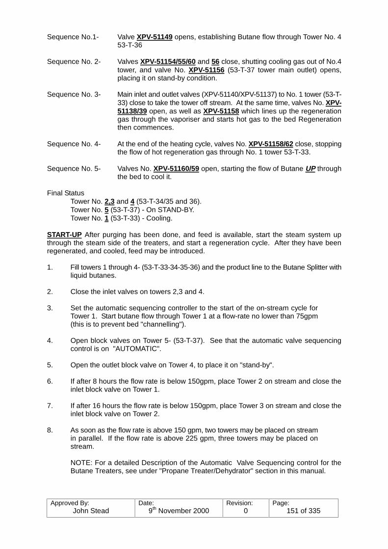
Approved By:John Stead
Date:9th November 2000
Revision:0
Page:151 of 335
Sequence No.1- Valve XPV-51149 opens, establishing Butane flow through Tower No. 453-T-36
Sequence No. 2- Valves XPV-51154/55/60 and 56 close, shutting cooling gas out of No.4tower, and valve No. XPV-51156 (53-T-37 tower main outlet) opens,placing it on stand-by condition.
Sequence No. 3- Main inlet and outlet valves (XPV-51140/XPV-51137) to No. 1 tower (53-T-33) close to take the tower off stream. At the same time, valves No. XPV-51138/39 open, as well as XPV-51158 which lines up the regenerationgas through the vaporiser and starts hot gas to the bed Regenerationthen commences.
Sequence No. 4- At the end of the heating cycle, valves No. XPV-51158/62 close, stoppingthe flow of hot regeneration gas through No. 1 tower 53-T-33.
Sequence No. 5- Valves No. XPV-51160/59 open, starting the flow of Butane UP throughthe bed to cool it.
Final StatusTower No. 2,3 and 4 (53-T-34/35 and 36).Tower No. 5 (53-T-37) - On STAND-BY.Tower No. 1 (53-T-33) - Cooling.
START-UP After purging has been done, and feed is available, start the steam system upthrough the steam side of the treaters, and start a regeneration cycle. After they have beenregenerated, and cooled, feed may be introduced.
1. Fill towers 1 through 4- (53-T-33-34-35-36) and the product line to the Butane Splitter withliquid butanes.
2. Close the inlet valves on towers 2,3 and 4.
3. Set the automatic sequencing controller to the start of the on-stream cycle forTower 1. Start butane flow through Tower 1 at a flow-rate no lower than 75gpm(this is to prevent bed "channelling").
4. Open block valves on Tower 5- (53-T-37). See that the automatic valve sequencingcontrol is on "AUTOMATIC".
5. Open the outlet block valve on Tower 4, to place it on "stand-by".
6. If after 8 hours the flow rate is below 150gpm, place Tower 2 on stream and close theinlet block valve on Tower 1.
7. If after 16 hours the flow rate is below 150gpm, place Tower 3 on stream and close theinlet block valve on Tower 2.
8. As soon as the flow rate is above 150 gpm, two towers may be placed on streamin parallel. If the flow rate is above 225 gpm, three towers may be placed onstream.
NOTE: For a detailed Description of the Automatic Valve Sequencing control for theButane Treaters, see under "Propane Treater/Dehydrator" section in this manual.

Approved By:John Stead
Date:9th November 2000
Revision:0
Page:152 of 335
Electrical Failure In case an electrical failure occurs, the regeneration gas cooler fans, Feedpumps, and Regeneration gas separator liquid pump will stop. All switching valves controller bythe Automatic Sequence controller will remain in the position they were in at the time the failureoccurred. Shut off the steam leaving the regeneration gas heater, otherwise there will be acontinuous loss of 55 bar steam from the system. Block in the feed pumps and their minimumflow line to prevent emptying the Dehydrator on stream towers and depressuring back to theSurge tank in case any of the check valves should leak.
Instrument Air Failure
All switching valves controlled by the Automatic Sequence Control will stay in the position theywere in at the time the failure occurred. Shut off the Regeneration Separator Pumps becausethe valve on the pump discharge line will close on air failure. All control valves will close andstop the steam bleed from the heaters, regeneration gas flow to the towers, and butane flowleaving them. Shut down the feed pumps and block them in as well as the minimum flow by-passes.
Miscellaneous
Sampling probes have been installed in each tower two feet below the top of the desiccant. These should be used for periodic testing of the beds capacity.
A continuous total sulphur analyser has been installed on the outlet product (AR-5107) that willsound an alarm if the sulphur content of the butanes become too high. Since water is morestrongly absorbed by the desiccant than sulphur compounds the sulphur compounds the sulphurwill break through long before the water.

Approved By:John Stead
Date:9th November 2000
Revision:0
Page:153 of 335
NGL TREATING & DEHYDRATION
BUTANE TREATER/DEHYDRATOR 53-E-15/16/19/20/21/22
EXCHANGERS/HEATERS/COOLERS
PRODUCTS SHELL TEMP TUBE TEMP PRESSUREEQUIP. No. DESCRIPTION
SHELL TUBE IN OUT IN OUT SHELL TUBE
No. TUBES & 512C
53-E-1516,19,20,21& 22
REGEN. GASHEATERS
800STEAM
BUTANES 800oC 520oC 100oC 620oC 800 275 48 ¾"/UNIT 20' LONG
REGEN. GAS COOLER
FANSEQUIP. No. DESCRIPTION TYPE PRESSURE
COOLINGSOURCE
NO/UNIT-DESCRIPTION
COOLERIN
TEMPOUT
53-E-12 REGEN.GASCOOLER
FINNED TUBEAIR FIN-4 PASS
(DESIGN)21.6 Bar G
AIR 3-2 SPEED. 2' DIA 4 BLADESEACH ELECTRIC DRIVE-RPM,960/480
288oC 38oC
VESSELS/DRUMS
EQUIP. No. SERVICE DESCRIPTION CAPACITY DIMENSION(mm)
MATERIALDESIGNPRESS
DESIGNTEMP.
53-T-33 34,35,36,3753-D-38
53-D-32
TREATERTOWERSREGEN. GASSEPARATORFEED SURGETANK
VERTICAL
VERTICAL
HORIZONTAL
13.1M3
9.2M3
57M3
1370 x 8840
1220 x 7620
274 x 9145
CARBONSTEELCARBONSTEELCARBONSTEEL
20.2 Bar G
20.2 Bar G
6.9 Bar G
343oC
344oC
58oC
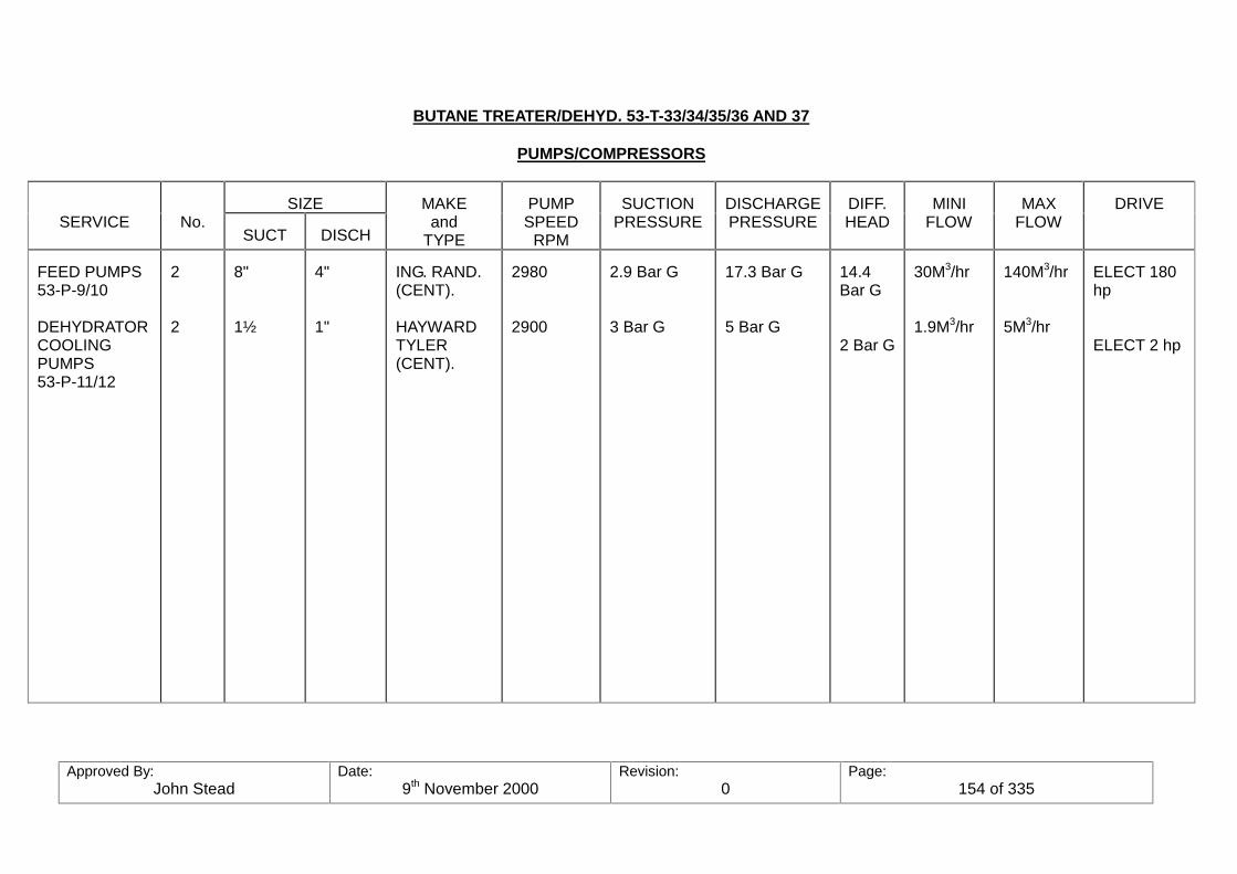
Approved By:John Stead
Date:9th November 2000
Revision:0
Page:154 of 335
BUTANE TREATER/DEHYD. 53-T-33/34/35/36 AND 37
PUMPS/COMPRESSORS
SIZESERVICE No.
SUCT DISCH
MAKEand
TYPE
PUMPSPEED
RPM
SUCTIONPRESSURE
DISCHARGEPRESSURE
DIFF.HEAD
MINIFLOW
MAXFLOW
DRIVE
FEED PUMPS53-P-9/10
DEHYDRATORCOOLINGPUMPS53-P-11/12
2
2
8"
1½
4"
1"
ING. RAND.(CENT).
HAYWARDTYLER(CENT).
2980
2900
2.9 Bar G
3 Bar G
17.3 Bar G
5 Bar G
14.4Bar G
2 Bar G
30M3/hr
1.9M3/hr
140M3/hr
5M3/hr
ELECT 180hp
ELECT 2 hp
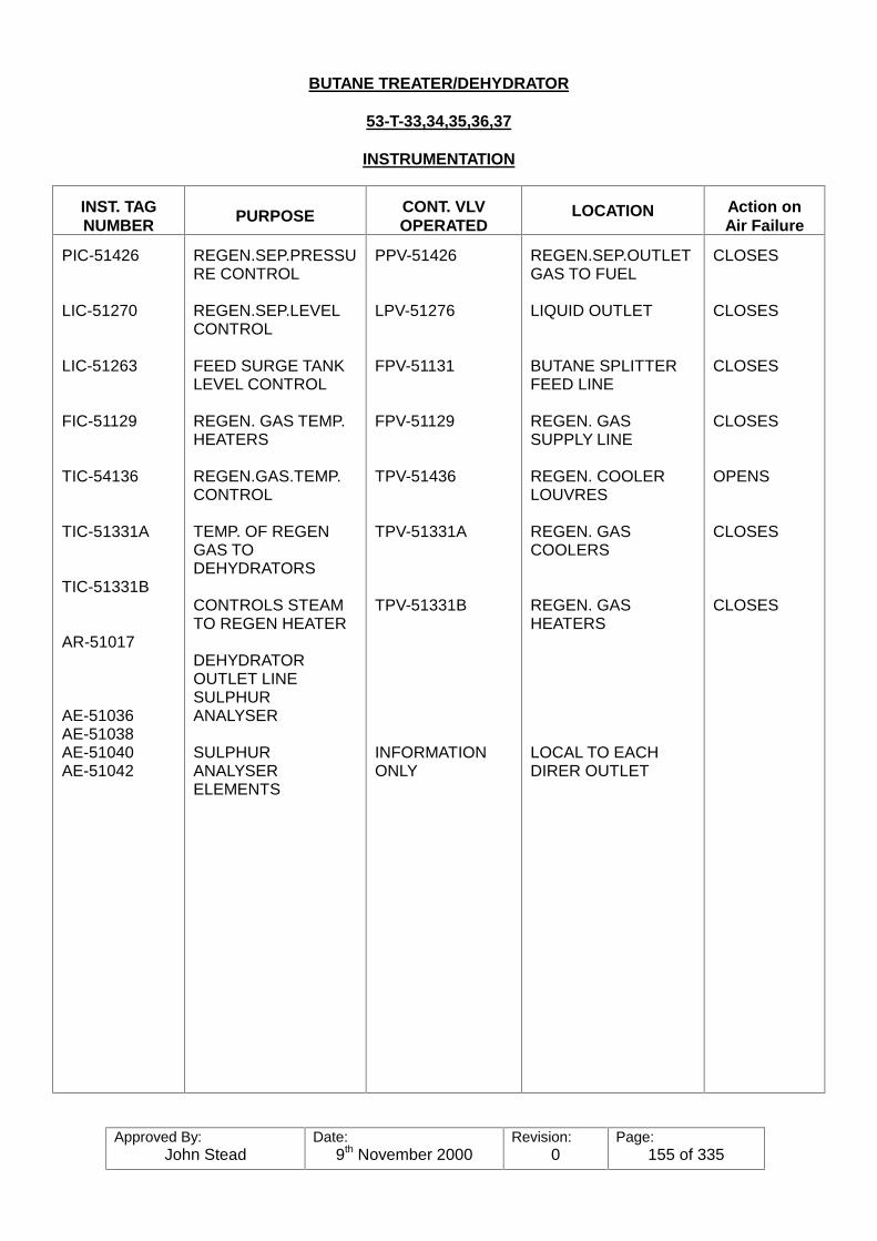
Approved By:John Stead
Date:9th November 2000
Revision:0
Page:155 of 335
BUTANE TREATER/DEHYDRATOR
53-T-33,34,35,36,37
INSTRUMENTATION
INST. TAGNUMBER PURPOSE CONT. VLV
OPERATEDLOCATION Action on
Air Failure
PIC-51426
LIC-51270
LIC-51263
FIC-51129
TIC-54136
TIC-51331A
TIC-51331B
AR-51017
AE-51036AE-51038AE-51040AE-51042
REGEN.SEP.PRESSURE CONTROL
REGEN.SEP.LEVELCONTROL
FEED SURGE TANKLEVEL CONTROL
REGEN. GAS TEMP.HEATERS
REGEN.GAS.TEMP.CONTROL
TEMP. OF REGENGAS TODEHYDRATORS
CONTROLS STEAMTO REGEN HEATER
DEHYDRATOROUTLET LINESULPHURANALYSER
SULPHURANALYSERELEMENTS
PPV-51426
LPV-51276
FPV-51131
FPV-51129
TPV-51436
TPV-51331A
TPV-51331B
INFORMATIONONLY
REGEN.SEP.OUTLETGAS TO FUEL
LIQUID OUTLET
BUTANE SPLITTERFEED LINE
REGEN. GASSUPPLY LINE
REGEN. COOLERLOUVRES
REGEN. GASCOOLERS
REGEN. GASHEATERS
LOCAL TO EACHDIRER OUTLET
CLOSES
CLOSES
CLOSES
CLOSES
OPENS
CLOSES
CLOSES

Approved By:John Stead
Date:9th November 2000
Revision:0
Page:156 of 335

Approved By:John Stead
Date:9th November 2000
Revision:0
Page:157 of 335
SETTING (mm)INST No. DESCRIPTION
HIGH LOWACTION
hhLA-51269
ILLA-51316
hiLA-51267
llLA-5136
XA-51165AXA-51165BXA-51165C
HIG LIQUID LEVEL INREGEN.SEP.
HIGH LIQUID LEVEL UNREGEN.SEP.
HIGH LIQUID LEVEL INREGEN.SEP
HIGH LIQUID LEVEL INREGEN.SEP
VIBRATION SWITCHESON COOLER FANS
2800
750
600
300
-
-
-
-
ALARMS
SHUTS DOWN COOLERFAN/FANS WITH EXCESSVIBRATION, AND GIVES ALARM
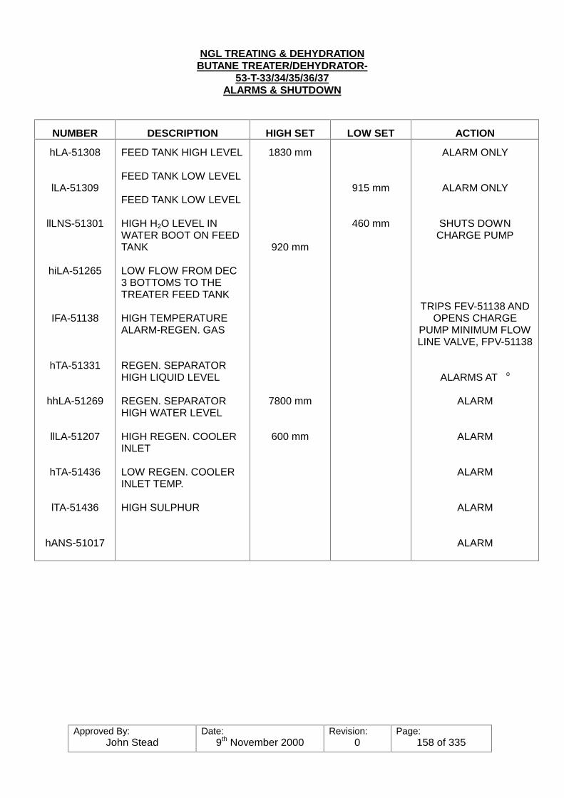
Approved By:John Stead
Date:9th November 2000
Revision:0
Page:158 of 335
NGL TREATING & DEHYDRATIONBUTANE TREATER/DEHYDRATOR-
53-T-33/34/35/36/37ALARMS & SHUTDOWN
NUMBER DESCRIPTION HIGH SET LOW SET ACTION
hLA-51308
lLA-51309
llLNS-51301
hiLA-51265
IFA-51138
hTA-51331
hhLA-51269
llLA-51207
hTA-51436
lTA-51436
hANS-51017
FEED TANK HIGH LEVEL
FEED TANK LOW LEVEL
FEED TANK LOW LEVEL
HIGH H2O LEVEL INWATER BOOT ON FEEDTANK
LOW FLOW FROM DEC3 BOTTOMS TO THETREATER FEED TANK
HIGH TEMPERATUREALARM-REGEN. GAS
REGEN. SEPARATORHIGH LIQUID LEVEL
REGEN. SEPARATORHIGH WATER LEVEL
HIGH REGEN. COOLERINLET
LOW REGEN. COOLERINLET TEMP.
HIGH SULPHUR
1830 mm
920 mm
7800 mm
600 mm
915 mm
460 mm
ALARM ONLY
ALARM ONLY
SHUTS DOWNCHARGE PUMP
TRIPS FEV-51138 ANDOPENS CHARGE
PUMP MINIMUM FLOWLINE VALVE, FPV-51138
ALARMS AT o
ALARM
ALARM
ALARM
ALARM
ALARM
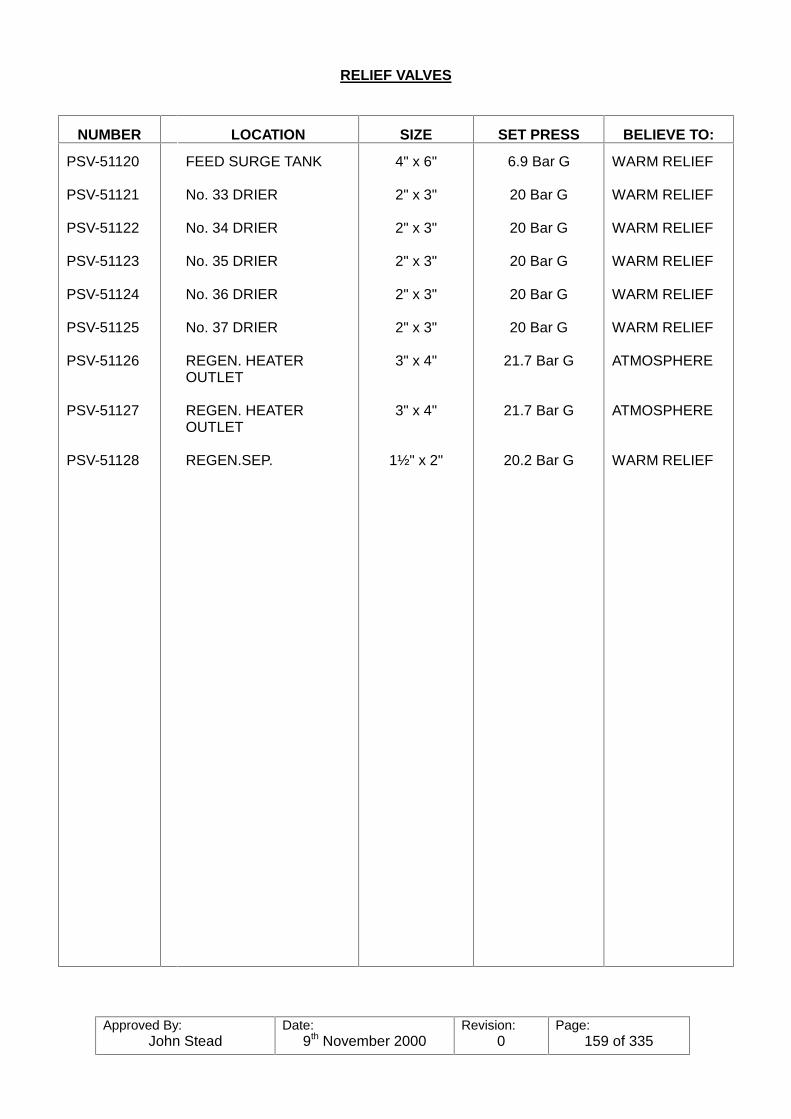
Approved By:John Stead
Date:9th November 2000
Revision:0
Page:159 of 335
RELIEF VALVES
NUMBER LOCATION SIZE SET PRESS BELIEVE TO:
PSV-51120
PSV-51121
PSV-51122
PSV-51123
PSV-51124
PSV-51125
PSV-51126
PSV-51127
PSV-51128
FEED SURGE TANK
No. 33 DRIER
No. 34 DRIER
No. 35 DRIER
No. 36 DRIER
No. 37 DRIER
REGEN. HEATEROUTLET
REGEN. HEATEROUTLET
REGEN.SEP.
4" x 6"
2" x 3"
2" x 3"
2" x 3"
2" x 3"
2" x 3"
3" x 4"
3" x 4"
1½" x 2"
6.9 Bar G
20 Bar G
20 Bar G
20 Bar G
20 Bar G
20 Bar G
21.7 Bar G
21.7 Bar G
20.2 Bar G
WARM RELIEF
WARM RELIEF
WARM RELIEF
WARM RELIEF
WARM RELIEF
WARM RELIEF
ATMOSPHERE
ATMOSPHERE
WARM RELIEF

Approved By:John Stead
Date:9th November 2000
Revision:0
Page:160 of 335
E-Butane Splitter5-T-11
1. Purpose and Service
The purpose of the ‘Butane Splitter is to take as feed, the bottoms product from both De-propanizer towers and separate the mixed butanes into iso-butane and normal butaneproducts for sales. The iso-butane is produced overhead, the normal butane from the5th tray outlet, and the remaining "heavies" from the bottom draw, or "drag" stream.
The overhead product will be routed directly to IC4-STORAGE (VIA Refrigeration), theside-draw to C-4 STORAGE, and the drag stream to stabilized crude storage or Deoilerfor further refining.
a. Feed
The feed to the Butane Splitter is the combined bottom product from the two De-propanizer after passing through the Butane Treater- Dehydrator mol sieve beds forremoval of traces of hydrogen sulphide and water. The calculated composition isapproximately 0.3 mol % propane, 29.4 % iso-butane, 70.2% normal butane and 0.1%pentanes-plus. The propane content, however, could run much higher if the De-propanizers are, for one reason or another, not making a good separation. Further, theproportions of butanes and pentanes-plus depend largely on the drag stream off thebottom of the tower, and the normal Butane stream to be taken off the side-draw product.
The feed from the treater Dehydrators is warmed by heat exchange with the De-propanizer bottom products to the treater dehydrators; wet feed/dry feed temperatureexchange. The only control on the Butane-Splitter feed temperature is with the three-waycontrol valve TPV-51264 & TPV-51265, which directs more or less De-propanizerbottoms product through, or around the De-propanizer bottoms coolers, 5-E-41/42. Thefeed temperature at this point is around 38oC (100oF). The stream remains liquid up tothe feed riser to the feed control valve FPV-51131 located at the elevation of the feedentry to the column. About 18% flashes to vapour upon entering the column.
b. Overhead Product
The overhead Product is high-purity iso-butane which must be at least 95 LV% iso-butane and meet the N.G.P.A. specifications for commercial butane, which include 4.8bar-g (70 psig) maximum vapour pressure at 38oC (100oF) and 2.0 LV % maximumpentanes-plus. With low propane content feed the composition should be approximately1.3 mol% propane, 95.5 mol% (95.7 LV%) isobutane, and 3.5 mol % n-butane withvapour pressure of 4.0 bar-g. at 38oC. (58 psig @ 100oF). When these specifications aremet it may be pumped directly to the chiller, and isobutane storage.
c. Sidedraw Product
The sidedraw (5th tray) is high purity normal butane which must be at least 95 LV %normal butane, and also meet the N.G.P.A. specifications for commercial butaneincluding maximum vapour pressure of 4.8 bar-g. (70 psig) at 38oC (100oF) and the feed,is expected to be approximately 1.3 mol % iso-butane, 98.6 mol % (98.6 LV %) normalbutane, and 0.1 mol % pentanes-plus. The vapour pressure must be about 2.6 bar-g.against sudden slugs of pentanes in the feed, but if pentanes-plus in the feed arepersistent, then the bottom draw (drag stream) must be used constantly at varied rates.

Approved By:John Stead
Date:9th November 2000
Revision:0
Page:161 of 335
d. Bottoms Product
(DRAG STREAM) The "drag" stream is necessary to remove heavies such as pentanesand heavier from the system. It is cooled in an airfin cooler and then pumped to eitherthe stabilizer bottom product line to stabilized crude oil storage or to the stabilizer bottomproduct recycle line to the crude booster pump suction or to the deoiler.
Note: Provisions are made to send either normal butane off the side-draw product, oriso-butane off the overhead product to the fuel system.
e. Separation
The key components to be separated are iso-butane and normal butane in the mainportion of the column. With the normal butane product being taken out if the side-draw,then the separation between the normal butane and heavies is in the bottom five trays. With good feed-low propane and pentane-plus content, about 97% of the iso-butanefrom the feed will be taken out over-head, and 98% of the normal butane from the feedwill go out the side-draw.
With the high propane content feed (De-propanizers not making a good cut) virtually thesame recoveries are required to make 95 LV % minimum iso-butane from the iso-butaneDepropanizer bottoms and 95 LV % minimum normal butane out the splitter side-draw. With high Pentanes-plus feed (assumed to be 0.5 mol %) of the Stabilizer Overhead partof the butane must be "wasted" out the bottom draw to reject the heavies. The traysbelow the side-draw will concentrate the heavies about ten-fold. In this case the heaviesin the bottom will be about 16 mol %. When they reach the 2 LV % (1 in 50) maximumallowable in the side-draw product above. Approximately 9% of the normal butane fromthe feed will have to go out the bottom draw to insure that pentanes-plus do not exceed2.0 LV % in the side-draw, and 90% of the normal butane is recovered from the feed tothe side-draw. Iso-butane recovery still needs to be 97% from the feed to the overhead.
2 Process Equipment and Flow Arrangements
a. The feed to the column comes directly from the outlet of the Butane DehydratorTreaters through a 6" line, through the Butane-splitter feed control valve FPV-51131 which is controlled by the liquid level control transmitter LNT-51263located on the Butane Dehydrator Treater feed surge tank 53-D-32 and entersthe column through nozzles on the 60th tray level. (Provisions are also made touse the 48th, and 54th tray level if necessary). The feed line is also carried onto the discharge piping of the side-draw product pump, 5-P-27/28 which can beused as a complete feed by-pass around the column. The energy required topump the feed is provided by the Butane Treater Dehydrator feed pump.
The feed is warmed by the Depropanizer K.P. interchanges 5-E-26/27/28/29/30/31/32/33 to around 85oC before entering the column. The feedflow control valve is located as near to the feed entries as possible to avoid atwo-phase flow in the vertical riser. The feed enters through the respectivenozzles into a feed distribution system on the inside which is designed to permitan even distribution over the tray.
The feed rate is determined by the flow of feed through the Butane DehydratorTreaters, thereby taking the swing. The by-pass line around the feed valve is apower actuated valve, HPV-51036 actuated by a hand controller, HIC-51036located on the board. It is also possible to switch the feed to the warm reliefsystem by operating power actuated valve HPV-51035 with controller HIC-51035.

Approved By:John Stead
Date:9th November 2000
Revision:0
Page:162 of 335
b. The column is 4270 mm (14’0") diameter and 61460 mm in height (about 201 feettall), and has 89 four-path valve trays on 610 mm (24 inch) vertical spacingexcept for the feed and side draw trays. These trays are different in that extraspace is provided in the feed trays, which have 1220 mm (48 inch) vertical;spacing to allow room for the feed distribution piping, and the sidedraw tray-which has a vertical spacing of 915 mm (36 inches) to provide room for thecollection troughs and draw off sumps at the end of each trough.
Liquid from the four-path bottom tray No. 1 flows into two side down-comers andone centre downcomer which effectively partitions the vapour space below. Achimney tray is provided 48" below tray No. 1 with vapour chimneys on each sideof the downcomer to distribute the reboiler vapours evenly to the two sides of thecentre. The liquid which comes down to the chimney tray flows across it withoutinterfering with the vapour and pours into the two side downcomers extendingdown beside the reboiler heater. The tower has a design pressure of 11.4 bar-g.and temperature of 90oC (195oF). It is provided with a 4" drain off the 10"bottoms line. Provisions are made for 3.5 bar-g steam or purge gas to beadmitted to the bottom for cleaning purposes.
The re-boilers are two internal horizontal two pass U-tube bundles located side-by-side in the bottom of the column. The bundles contain 512 1" OD carbonsteel tubes each. Total heating area is 1340 square feet. The reboilersvapourize about 98% of the liquid reaching the bottom of the column when theside-draw is used to remove normal butane, or about 86% when the normalbutane product is allowed to come off the bottom. The rest of the liquid is drawnoff as bottom product.
c. The column overhead vapours flow from the top of the column through the 24"overhead vapour line through the main column back pressure control valve, 24"- PPV-51439 on through another pressure control valve, PPV-51413-A an donout through the overhead vapour condensing coils (5-E-37) and into theaccumulator, (5-D-22). The accumulator pressure maintenance line tees off themain column overhead vapour line at point Between PPV-51439 and PPV-51443A and goes through another pressure control valve 8" PPV-51443-B, andon into the top of the accumulator. Valves PPV-51443-A accumulator pressuretransmitter calls for additional hot make-up gas PPV-51443-A pinches backagainst the main tower overhead vapour flow, and with the same signal, opensPPV-51443-B, forcing more hot gas around the overhead condenser through theby-pass and straight to the top of the accumulator.
In order to be able to perform maintenance work on the main column backpressure controller, PPV-51439, a 20" by-pass line was installed with a pressurecontrol valve, 20" PPV-51433 installed in to which can be used for columnpressure control while the maintenance is being done. in order to have controlon the accumulator pressure during this time, an 8" cross-over line, with PPV-5144D installed in to, is tied across from the main 20" by-pass line to the regular10" accumulator pressure maintenance line (See Fig. 1).
d. The vapours are totally condensed and slightly sub-cooled, and collected in theaccumulator 5-D-22 which is a horizontal vessel 10,550 mm long by 3,500 mmin diameter. It is made of carbon magnesium steel, has a design pressure of11.7 bar-g. (173 psig) and temperature rating of 80oC maximum (176oF) and -10oC (14oF) minimum. Operating temperature is 38oC (100oF) and pressure 5Bar G. The vessel has a capacity of 108 M3 and will provide about six minutesof surge time when half full of liquid.

Approved By:John Stead
Date:9th November 2000
Revision:0
Page:163 of 335
e. The Overhead Product is taken off the discharge of the reflux pump through asix inch line where the overhead product can be switched to two different places.If it is specification iso-butane it is sent to the iso-butane chillers and storage. Itcan also be routed to the butane fuel vaporiser and used for plant fuel.
f. The Reflux Pumps 5-P-29/30 are both electrically driven centrifugal pumps witha rated capacity of 654M3/hr., 115M head and rated discharge pressure of 11.7bar-g. They are driven by a 200 k.w 3 phase 50 cycle electric motor at 1450RPM.
The sidedraw product leaves the column from the 5th tray level through two 8"nozzles and manifold into the 10" main sidedraw product line. It is routed to thesuction of the Butane Product pump 5-D-27/28 (No. 28 being the stand-by for No.27) and discharges from the pump through a 6" line and routed through theButane product air fin cooler 5_e-38 (Four Fans). From here, it goes through the5th tray product control valve FPV-51135 and on to the normal butane chillingrefrigerated storage area, or can be routed to the butane fuel vaporiser to beused as plant fuel.
g. The "drag" stream is the residual heavies that leave from the bottom of thetower through a 10 inch line to the suction of the Drag pump 5-P-26 where itdischarges into a 2" line through the Drag stream cooler, 5-E-44 for cooling. itthen goes through control valve FPV-51136 where it can be switched to the crudeproduct storage or be recycled to the stabilizers or used as deoiler feed.
3. Operating Conditions
The accumulator pressure is set at 5 Bar G to permit complete condensing of theoverhead vapour at 38oC (100oF) by airfin condensers at summertime conditions withpropane contents up to 51 mol %. With lower propane contents the overhead will besomewhat subcooled at 380C. The column top is calculated to operate at 6 Bar G and55 to 57oC, (131o- 135oF) depending on the propane content. The bottom is to operateat 6.6 Bar G (125 pisa) and 75o to 79oC (167-174oF), depending on the amount ofpentanes-plus content. The sidedraw tray when normal butane product is made from thesidedraw should be about 75oC (167oF).
The re-boilers are heated with 3.4 bar-g. steam at 148oC (298oF) temperature. Thecondensate return pump is capable of taking suction as low as atmospheric pressureand pumping it to the condensate system at 6 Bar G.
The feed is pre-heated to 85oC (185oF) in the heat exchange with the De-propanizerbottoms and then cooled to around 67oC (153oF) as it flashes around 18% vapour at thecolumn feed entry.
The overhead product is taken directly off the reflux pump discharge line at 38oC (100oF)and 12.4 Bar g (194 pisa) which is sufficient pressure to go to the refrigerated isobutanestorage or to the butane fuel system.
The normal butane, whether taken from the side draw or the column bottom, is cooledby air fin coils to 38oC and 6.9 bar-g or lower if the weather is cooler.
Pump number 5-P-26 is the regular bottoms drag stream pump. Pump number 5-P-27is the normal side draw pump, but can be switched to be used as a booster pump, orstand-by pump for the drag stream pump if no side draw is being removed. Pumpnumber 5-P-28 the stand-by for the regular side draw pump.
Approved By:John Stead
Date:9th November 2000
Revision:0
Page:164 of 335
The column and auxiliary equipment are sized to handle about 7% additional feed andreflux than normal. According to calculations based on the original crude compositionand rates the feed rate would be around 126.6M3/hr. Reflux is calculated to be 514M3/he @ 3811oC.
4. Control System
The feed to the Butane Splitter is controlled by the liquid level control LIC-51263 from theButane Dehydrator Treater Feed Surge Drum, 53-D-32. The level in the treater feedsurge tank remains constant with the feed rate tot he Butane Splitter taking the swing. A power operated valve HPV-51036 is operated remotely be using the HIC-51036mounted panel board. A check valve in the feed line near the column will prevent anyback flow from the tower to the warm relief system. This was done due to the locationof the feed control valve which is near the feed tray entry on the tower. The feedtemperature is controlled by adjusting the Depropanizer Kettle product cooler by-passcontrol valve, 3-way TPV-51295 with TIC-51295, by adjusting the controllable louvres(with HIC-51031) or by starting to stopping one of the fans.
Steam to the reboilers is on flow control FPV-51132 which is re-set by the column bottomliquid level control LIC-51278 which is directly affected by the amount of side draw anddrag stream flow taken off. The condensate level in the condensate accumulator iscontrolled by a liquid level controller which controls the amount of condensate being pumped out to hold the level.
The Bottom Drag stream is on flow control, FIC-51136 which re-sets control valve FPV-51136 located in the Drag stream line. The side draw product rate is on flow control FIC-51135 which is re-set either by (1) tray No. 70 temperature control TIC-51353, or, (2) bythe Butane Splitter Distillation Column Control. The choice is made by a manual selectorswitch. The Distillation Column Control works by maintaining a pre-set amount ofisobutane in the sidedraw product, and the tray temperature controller works be holdinga pre-set temperature on the control tray.
Power actuated valve, HPV-51040 is provided to switch all the bottom product to thewarm relief if necessary.
Column pressure is on back pressure control at the overhead vapour line upstream ofthe condensers. A pressure transmitter, PNT-51439 mounted on the column overheadvapour line transmits the pressure to the pressure controller PIC-51439 which resets thecontrol valve PPV-51439 located in the overhead vapour line.
Reflux temperature is not directly controlled, but the louvres on the air fin condensers areadjusted by TIC-51351 to maintain 38oC inlet reflux accumulator.
Accumulator pressure is maintained by a pressure maintenance system utilizing a hotgas line off the column overhead vapour line with two control valves, PPV-51443A andPPV-51443B operating from a split range control signal from the accumulator pressuretransmitter. As the accumulator calls for pressure, PPV-51443B opens, and PPV-51443A pinches back insuring vapour to by-pass the cooling coils directly to theaccumulator.
External Reflux rate is on flow control, FIC-51133 reset by the Distillation ColumnControl, or can be controlled by straight "rate of flow" control.
The Overhead Product rate is on flow control, FIC-51134 reset by the accumulator levelcontrol, LIC-51282.
Approved By:John Stead
Date:9th November 2000
Revision:0
Page:165 of 335
The Distillation Column Control employs a computer to implement feed forward andfeed back control of the Butane Splitter by using the input signals from the feed rate,reflux and overhead temperatures, and the normal butane product composition. Theoutput signals from the computer are used to reset the reflux and normal butane flowcontrollers. If the Distillation Column control is out of order for one reason or another,the conventional tray temperature control may be used. The reflux is adjusted with feedrate changes to maintain bottom-to-feed ratio, and with the normal butane analysis tomaintain specific composition.
An analyser is used to determine the composition of the normal butane product, and thecontrolling factor for the Column Distillation Control is the percent of isobutane in the sidedraw product. The overhead product must be monitored, however, either by laboratorychecks, or weathering samples to determine the amount of normal butanes carried overalong with the isobutane.#
5. Alarms-Safety Features
All control valves are designed to "Fail Safe" in case of instrument air, or power failure. In case of the former, the valves will open or close to permit the column to block in thefeed, and product stream and allows the overhead vapour to carry on through to theaccumulator, to be refluxed back over the column. In case of power failure, the refluxpump would be down-however, the controls would be active as long as the batterypowered back up units were active. In this case you would be able to utilize theinstruments until (1) either the power is restored, or (2) to shut down the column safety.
Column over-pressure devices are designed to have four stages of protection withincreasing pressure which are: (1) Alarm (2) Steam shut off, (3) Vent to relief system, and(4) last resort, vent to the atmosphere from the top of the column. The tower has three6 x 10 relief valves, PSV-51131A, PSV-51131B and PSC-51131C mounted on theoverhead vapour line with a set pressure of 13.7 bar-g. These are the last resort reliefvalves mentioned above. The accumulator also has a relief valve; PSV-51132, A 4" x 6"with a set pressure of 11.7 bar-g that relieves into the enclosed warm relief system. Also,relief valves PSV-51130 A and B, 6" x 10" set at 10.8 bar-g., PSV-51130C-6" x 8" set at10.4 bar-g are mounted on the overhead vapour line, and relieve to the warm ventsystem.
Automatic shut-offs with alarm are also provided on the following:Sidedraw product control valve shut-off on low liquid level-IILNS-51273Reflux and overhead product pump shut-offs on low liquid level-IILA-51286Condenser air fin shut offs on excessive vibration: butane cooler fans-XA-51168Athrough D.drag stream cooler fans-XA-51205 A through Boverhead condenser fans-XA-51167 A through M
Other alarms are as follows:Column high level - hLA-51279Column low level - ILA-51290Column high differential pressure - hdPA-51435Low steam condensate pot level - ILA-51276Accum. high level - hLA-51283Accum. low level - ILA-51284Reflux flow low flow - IFA-51133Normal butane low flow - IFA-51135Pentane Drag steam low pressure - IPA-51463
Approved By:John Stead
Date:9th November 2000
Revision:0
Page:166 of 335
6. Operating Procedures
Preparatory to start-up all utilities must be service, instrumentation checked out and allrotating equipment tested. Steam supply must be warmed up and drained of liquid to thecontrol valve. One or both De-propanizers as well as the Butane Treater Dehydratormust be operating to furnish suitable feed for the Butane Splitter. Also, all air must bepurged from the system with inert gas, fuel gas, or steam, but due to the cold conditionsthe products will be subjected to during the refrigerated storage preparation, must be asdry as possible.
a. A suggested procedure to purge the column of air follows:The object is to displace the air from the tower and all associated piping vessel.Purge gas is available to use as a purging agent simply by a quick swing hookup from the tower bottom to the purge gas line-4"-651T73-525. The idea is todisplace the air with the gas from the bottom of the tower, out through theoverhead vapour liner, through each and every condensing coil separately, on outthrough the liquid overhead run-down line, into the accumulator and out to theatmosphere. Reflux piping must be backed through from the tower, out throughthe reflux pump bleeders.
After the gas is hooked up, make sure all unauthorized personnel are out of thearea, chain gates up, and everyone involved notified. Open the 4" bleeder on topof the column, and the 3" bleeder on the overhead vapour line near the controlvalves. Have all but one overhead condenser coils blocked in. Have inlet lateralbleeder open on the one that is open. Have the blind plate removed and the 3"bleeder, as well as the gauze glass and float barrel bleeders open refluxaccumulator. Open the 10" suction valves to the overhead and reflux pumps, butleave the discharge valves closed as this time. Open the reflux valve, FPV-51133 with the control and open the down stream isolating valve, block upstreamside. Open reflux pump case bleeder, and bleeder on the reflux control valve. Open all the bleeders on the column bottom level control and gauge glasses. Open the 10" suction line from the side draw tray through the suction valve of theside draw, and stand by side draw pumps-5-P-27/28 but leave the dischargevalves closed at this time and open pump case bleeders. Do the same with thedrag stream pump, 5-P-26.
Admit gas -or nitrogen-slowly at first until a good flow established. Start checkingbleeders immediately around the column bottom level, and bottom product pumpcase bleeders-shut off bleeders when no air is evident. (do the same with allbleeders as no air is evident). The next spot will be the bottom gauge glassesand the float barrels-block off bleeders needed. Continue monitoring bleeders,especially the reflux control valve bleeder as vapour, or nitrogen will show uphere shortly before, or about the same time as it does on the top-close off topbleeders when vapour or nitrogen is evident here, continue through the normalflow path checking bleeders, and blocking bleeders off as air is expelled. Whenpurge gas is evident as the overhead vapour condensing coils sweep out he firstcoil, then open and sweep out he next one until all have being cleared. By thistime, some vapours (N2 or gas) should be showing up on the accumulator vents. Block in when you are well satisfied that all the air has been expelled here. When the reflux pumps are cleared, open the vents. On the overhead productline at the motor valve setting; go through the inlet valve, and out the bleeder. Open the by-pass line around the control valve also, and clear it. Block in thereflux motor valve isolating valve on the down-stream side-(next to column), andopen the upstream block valve and bleeders. Open the reflux pump dischargesvalves. This should clear the other half of the long reflux line.
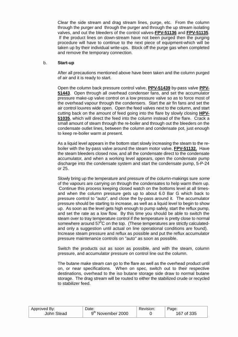
Approved By:John Stead
Date:9th November 2000
Revision:0
Page:167 of 335
Clear the side stream and drag stream lines, purge, etc. From the columnthrough the purger and through the purger and through the up stream isolatingvalves, and out the bleeders of the control valves-FPV-51136 and FPV-51135. If the product lines on down-stream have not been purged then the purgingprocedure will have to continue to the next piece of equipment-which will betaken up by their individual write-ups. Block off the purge gas when completedand remove the temporary connection.
b. Start-up
After all precautions mentioned above have been taken and the column purgedof air and it is ready to start.
Open the column back pressure control valve, PPV-51439 by-pass valve PPV-51443. Open through all overhead condenser fans, and set the accumulatorpressure make-up valve control on a low pressure valve so as to force most ofthe overhead vapour through the condensers. Start the air fin fans and set theair control louvres wide open. Open the feed valves next to the column, and startcutting back on the amount of feed going into the flare by slowly closing HPV-51035, which will direct the feed into the column instead of the flare. Crack asmall amount of steam through the re-boiler and through out the bleeders on thecondensate outlet lines, between the column and condensate pot, just enoughto keep re-boiler warm at present.
As a liquid level appears in the bottom start slowly increasing the steam to the re-boiler with the by-pass valve around the steam motor valve, FPV-51132. Havethe steam bleeders closed now, and all the condensate direct to the condensateaccumulator, and when a working level appears, open the condensate pumpdischarge into the condensate system and start the condensate pump, 5-P-24or 25.
Slowly bring up the temperature and pressure of the column-makings sure someof the vapours are carrying on through the condensates to help warm them up. Continue this process keeping closed watch on the bottoms level at all times-and when the column pressure gets up to about 6.0 Bar G which back topressure control to "auto", and close the by-pass around it. The accumulatorpressure should be starting to increase, as well as a liquid level to begin to showup. As soon as the level gets high enough to pump safely, start the reflux pump,and set the rate as a low flow. By this time you should be able to switch thesteam over to tray temperature control if the temperature is pretty close to normalsomewhere around 570C on the top. (These temperatures are strictly calculated-and only a suggestion until actual on line operational conditions are found). Increase steam pressure and reflux as possible and put the reflux accumulatorpressure maintenance controls on "auto" as soon as possible.
Switch the products out as soon as possible, and with the steam, columnpressure, and accumulator pressure on control line out the column.
The butane make steam can go to the flare as well as the overhead product untilon, or near specifications. When on spec, switch out to their respectivedestinations, overhead to the iso butane storage side draw to normal butanestorage. The drag stream will be routed to either the stabilized crude or recycledto stabilizer feed.

Approved By:John Stead
Date:9th November 2000
Revision:0
Page:168 of 335
c. Shut-down
When it is necessary to completely shut down the column and purge the systemfor repair work the following procedure is suggested:-
Notify Boiler House
Take the Column Distillation Control out of service. Switch the feed to flare or spike and keepit Over head and Bottoms products to storage as long as practicable - then return to spike untillevels are reduced to minimum. Shut off all steam. Lower the column back pressure motorvalve setting to keep the valve in the open position as the column pressure decreases-loweraccum. Pressure control pointer to low pressure valve to make certain as much liquid aspossible is pushed out of the overhead air fin coils-shut down fans, shut down the side drawpump as soon as it gasses off.
Note: The low level shut down devices for the side draw pump and low flow shut down for thereflux may have to be temporarily by-passed to completely empty the column. Get rid of all liquidpossible, then open the vents, and depressure. Drain any residual to the respective drains.
d. Vapour Purge
After the tower and equipment is depressured, tie-in steam to the bottom of thetower, and begin steaming it out.
Open the vents on the top of the column, overhead vapour line, accumulator andbegin to steam out. When vapour free, shut in the steam. The column in nowready for blinding. After blinding (using butterfly flanges next to blinds) steam thesystem once more, depressure, and open up as necessary.
Note: It will be necessary to steam through the coils separately to completelyinsure them being clear.
e. Refluxing and Column
When the column is to be taken off steam for a short period of time it can be puton total reflux. If the reason is loss of feed, the feed meter will go to zero andcause the Distillation Column Control to shut off the side steam flow and willreduce reflux to a low rate. In this case, all that is necessary to do is to manuallyblock in the product isolating valves to prevent any leakage. The column willcontinue to operate.
If however, the reason for refluxing the column is due to the flare-(in case it is offspec, for instance) the feed meter will still see a feed flow, and consequentlywould eventually empty the column as the Distillation Column Control wouldkeep the sidedraw product flowing. The Distillation Column Control, in this case,would have to be taken off control and substituted for with tray temperaturecontrol. It would still be manually block in all the product isolating valves-especially the drag steam.
f. Power Failure
As outlined previously, the column id designed to "fail" safe during a powerfailure-but many times the power failure will be a "dip" type-just long enough toshut down the pump motors. In some cases, the failure will be scattered-that issome pumps down, and others still running. In any case, however, the first thingto do is to get the air fin fans started again followed by the reflux, and theproducts. (if you still need feed). Speed is essential in a assessing the situation,
Approved By:John Stead
Date:9th November 2000
Revision:0
Page:169 of 335
and making the proper moves at the right time.
If the failure is complete, and does not come back on very quickly, then treat thesituation as a complete shut down and start blocking the product lines. Thecolumn will no doubt overpressure and "pop" due to the sudden loss of topcooling, and heat in the bottom. Get the steam out as soon as possible.
g. Instrument Air Failure
In case of total instrument air failure, the controls will fail safe, as outlined in theprevious section. But in most cases, if this ever happens, the entire plant will beaffected resulting in erratic, and off-spec. feed to the column. Switch the feed,and products to the flare and shut the steam out of the column if not already out.
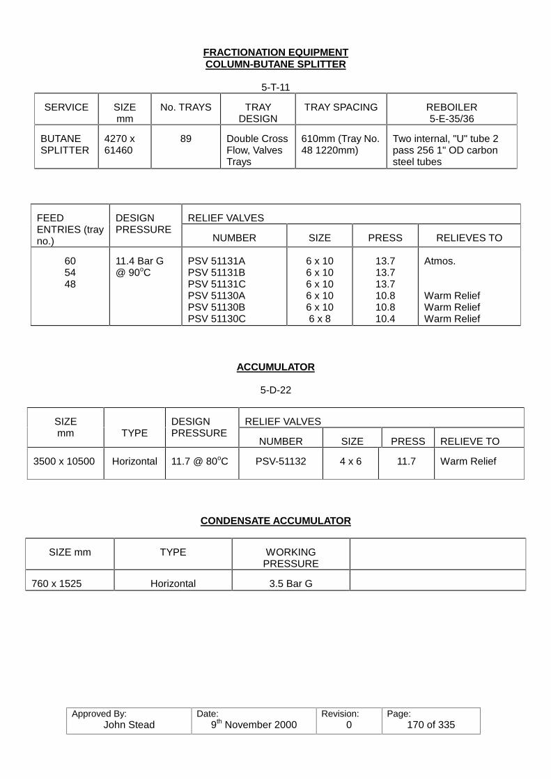
Approved By:John Stead
Date:9th November 2000
Revision:0
Page:170 of 335
FRACTIONATION EQUIPMENTCOLUMN-BUTANE SPLITTER
5-T-11
SERVICE SIZEmm
No. TRAYS TRAYDESIGN
TRAY SPACING REBOILER5-E-35/36
BUTANESPLITTER
4270 x61460
89 Double CrossFlow, ValvesTrays
610mm (Tray No.48 1220mm)
Two internal, "U" tube 2pass 256 1" OD carbonsteel tubes
RELIEF VALVESFEEDENTRIES (trayno.)
DESIGNPRESSURE
NUMBER SIZE PRESS RELIEVES TO
605448
11.4 Bar G@ 90oC
PSV 51131APSV 51131BPSV 51131CPSV 51130APSV 51130BPSV 51130C
6 x 106 x 106 x 106 x 106 x 106 x 8
13.713.713.710.810.810.4
Atmos.
Warm ReliefWarm ReliefWarm Relief
ACCUMULATOR
5-D-22
RELIEF VALVESSIZEmm TYPE
DESIGNPRESSURE
NUMBER SIZE PRESS RELIEVE TO
3500 x 10500 Horizontal 11.7 @ 80oC PSV-51132 4 x 6 11.7 Warm Relief
CONDENSATE ACCUMULATOR
SIZE mm TYPE WORKINGPRESSURE
760 x 1525 Horizontal 3.5 Bar G
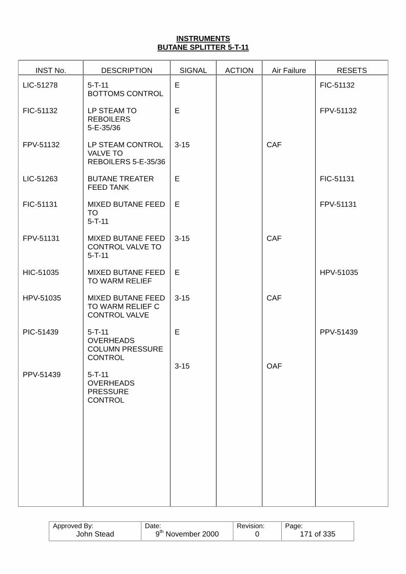
Approved By:John Stead
Date:9th November 2000
Revision:0
Page:171 of 335
INSTRUMENTSBUTANE SPLITTER 5-T-11
INST No. DESCRIPTION SIGNAL ACTION Air Failure RESETS
LIC-51278
FIC-51132
FPV-51132
LIC-51263
FIC-51131
FPV-51131
HIC-51035
HPV-51035
PIC-51439
PPV-51439
5-T-11BOTTOMS CONTROL
LP STEAM TOREBOILERS5-E-35/36
LP STEAM CONTROLVALVE TOREBOILERS 5-E-35/36
BUTANE TREATERFEED TANK
MIXED BUTANE FEEDTO5-T-11
MIXED BUTANE FEEDCONTROL VALVE TO5-T-11
MIXED BUTANE FEEDTO WARM RELIEF
MIXED BUTANE FEEDTO WARM RELIEF CCONTROL VALVE
5-T-11OVERHEADSCOLUMN PRESSURECONTROL
5-T-11OVERHEADSPRESSURECONTROL
E
E
3-15
E
E
3-15
E
3-15
E
3-15
CAF
CAF
CAF
OAF
FIC-51132
FPV-51132
FIC-51131
FPV-51131
HPV-51035
PPV-51439

Approved By:John Stead
Date:9th November 2000
Revision:0
Page:172 of 335
INSTRUMENTS
BUTANE SPLITTER 5-T-11
INST No. DESCRIPTION SIGNAL ACTION Air Failure RESETS
HIC-51037
HPV-51037
5-T-11OVERHEADSCONDENSER5-E-37
5-T-11OVERHEADSCONDENSER5-E-37
LOUVRE CONTROL
E
3-15
HPV-51037

Approved By:John Stead
Date:9th November 2000
Revision:0
Page:173 of 335
INSTRUMENTSBUTANE SPLITTER 5-T-11
INST No. DESCRIPTION SIGNAL ACTION Air Failure RESETS
PIC-51443
PPV-51443A
PPV-51443B
PPV-51443C
PPV-51443D
FIC-51133
FPV-51133
OVERHEADSACCUMULATOR5-D-22PRESSURECONTROL
OVERHEADSACCUMULATOR5-D-22CONTROL VALVECONDENSER5-E-37
OVERHEADSACCUMULATOR5-D-22BY-PASS CONTROLVALVE OVERCONDENSER5-E-37
OVERHEADSACCUMULATOR5-D-22CONTROL VALVE TOCONDENSER5-E-37
OVERHEADSACCUMULATOR5-D-22BY-PASS CONTROLVALVE OVERCONDENSER5-E-37
5-T-11REFLUX CONTROL
5-T-11REFLUX CONTROLVALVE
E
E
3-15
OAF
CAF
OAF
CAF
OAF
PPV-51443APPV-51443BPPV-51443CPPV-51443D
FPV-51133
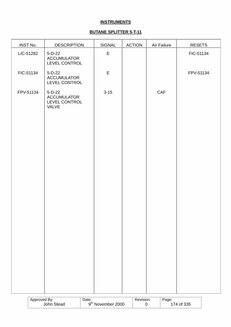
Approved By:John Stead
Date:9th November 2000
Revision:0
Page:174 of 335
INSTRUMENTS
BUTANE SPLITTER 5-T-11
INST No. DESCRIPTION SIGNAL ACTION Air Failure RESETS
LIC-51282
FIC-51134
FPV-51134
5-D-22ACCUMULATORLEVEL CONTROL
5-D-22ACCUMULATORLEVEL CONTROL
5-D-22ACCUMULATORLEVEL CONTROLVALVE
E
E
3-15 CAF
FIC-51134
FPV-51134

Approved By:John Stead
Date:9th November 2000
Revision:0
Page:175 of 335
INSTRUMENTSBUTANE SPLITTER 5-T-11
INST No. DESCRIPTION SIGNAL ACTION AirFailure
RESETS
HIC-51038
HPV-51038
TIC-51353(TRAY 705-T-22)
FIC-51135
FPV-51135
HIC-51075
HPV-51075
FIC-51136
5-T-11OVERHEADSPRODUCT TO WARMRELIEF
5-T-11OVERHEADSPRODUCT TO WARMRELIEF CONTROLVALVE
5-T-11NORMAL BUTANERUNDOWN
5-T-11NORMAL BUTANERUNDOWN
5-T-11NORMAL BUTANERUNDOWNCONTROL VALVE
5-T-11NORMAL BUTANERUNDOWN TO WARMRELIEF
5-T-11NORMAL BUTANERUNDOWN TO WARMRELIEF CONTROLVALVE
5-T-11PENTANE DRAGRUNDOWN
E
3-15
E
9-15
E
3-15
E
WHEN FIC-51135OF PRIMARYCONTROL
CAF
CAF
HPV-51038
FIC-51135
FPV-51135
HPV-51075
FPV-51136

Approved By:John Stead
Date:9th November 2000
Revision:0
Page:176 of 335
INSTRUMENTSBUTANE SPLITTER 5-T-11
INST No. DESCRIPTION SIGNAL ACTION AirFailure RESETS
FPV-51136
HIC-51040
HPV-51040
5-T-11PENTANE DRAGRUNDOWNCONTROL VALVE
5-T-11PENTANE DRAGRUNDOWN TO WARMRELIEF
5-T-11PENTANE DRAG TOWARM RELIEFCONTROL VALVE
3-15
E
3-15
CAF
CAF
HPV-51040

Approved By:John Stead
Date:9th November 2000
Revision:0
Page:177 of 335
PRESSURE SAFETY VALVESBUTANE SPLITTER 5-T-11
INST No. DESCRIPTION SIGNAL ACTION Air Failure RESETS
PSV-51130A
PSV-51130B
PSV-51130C
PSV-51131A
PSV-51131B
PSV-51131C
PSV-51132
5-T-11COLUMNOVERHEADSVAPOUR LINE
" "
" "
" "
" "
" "
5-D-22ISO-BUTANECOLUMN REFLUXACCUMULATOR
10.8 Bar G
10.8 Bar G
10.4 Bar G
13.7 Bar G
13.7 Bar G
13.7 Bar G
11.7 Bar G
6" x 10"
6" x 10"
6" x 10"
6" x 10"
6" x 10"
6" x 10"
4" x 6"
ISO-BUTANE
ISO-BUTANE
ISO-BUTANE
ISO-BUTANE
ISO-BUTANE
ISO-BUTANE
ISO-BUTANE
WARM RELIEF
WARM RELIEF
WARM RELIEF
ATMOS
ATMOS
ATMOS
WARM RELIEF
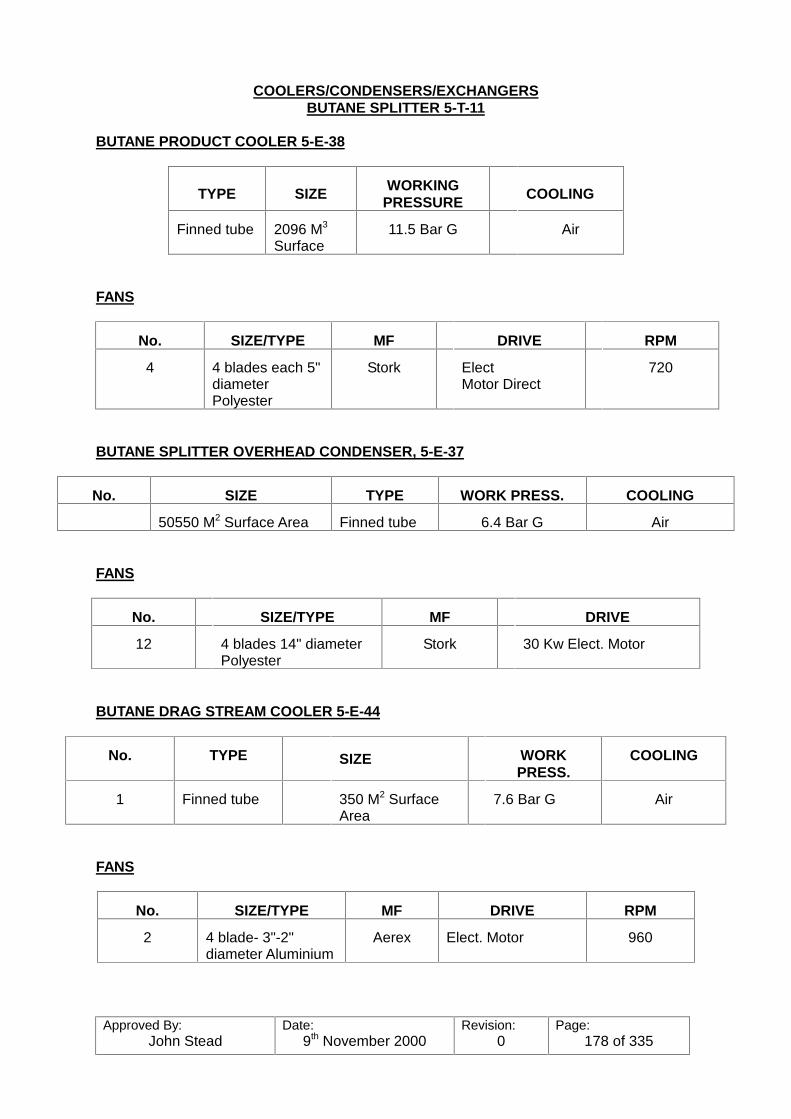
Approved By:John Stead
Date:9th November 2000
Revision:0
Page:178 of 335
COOLERS/CONDENSERS/EXCHANGERSBUTANE SPLITTER 5-T-11
BUTANE PRODUCT COOLER 5-E-38
TYPE SIZE WORKINGPRESSURE COOLING
Finned tube 2096 M3
Surface11.5 Bar G Air
FANS
No. SIZE/TYPE MF DRIVE RPM
4 4 blades each 5"diameterPolyester
Stork ElectMotor Direct
720
BUTANE SPLITTER OVERHEAD CONDENSER, 5-E-37
No. SIZE TYPE WORK PRESS. COOLING
50550 M2 Surface Area Finned tube 6.4 Bar G Air
FANS
No. SIZE/TYPE MF DRIVE
12 4 blades 14" diameterPolyester
Stork 30 Kw Elect. Motor
BUTANE DRAG STREAM COOLER 5-E-44
No. TYPE SIZE WORKPRESS.
COOLING
1 Finned tube 350 M2 SurfaceArea
7.6 Bar G Air
FANS
No. SIZE/TYPE MF DRIVE RPM
2 4 blade- 3"-2"diameter Aluminium
Aerex Elect. Motor 960

Approved By:John Stead
Date:9th November 2000
Revision:0
Page:179 of 335
PUMPS/COMPRESSORS
BUTANE SPLITTER 5-T-11
SIZESERVICE No.
SUCT. DISCH
MAKEand
TYPE
PUMPSPEED
RPM
SUCTIONPRESSURE
BAR G
DISCHARGEPRESSURE
BAR G
DIFF.HEADBAR G
MIN.FLOWM3/HR
MAX.FLOWM3/HR
DRIVE
BUTANE PROD.5-P-27/28
REBOILERCOND.5-P-24/25
BOTTOMS(DRAG) 5-P-26
REFLUX5-P-29/30
ISO-BUTANEBOOSTER5-P-31/32
2
2
1
2
2
6
4
4
14
6
4
3
2
8
3
ING. RANDCENT.
ING. RANDCENT.
ING. RANDCENT.
ING. RANDCENT.
ING. RANDCENT.
2950
2950
2950
1470
2920
7.5
2
7.6
5.9
11.5
11.5
6.1
12.1
11.7
18.9
4
4.1
4.5
5.8
7.4
16.5
8
6
130
16
114
60
11.4
654
50
ELECT.40 HP
ELECT.20 HP
ELECT.20 HP
ELECT.270 HP
ELECT.50 HP
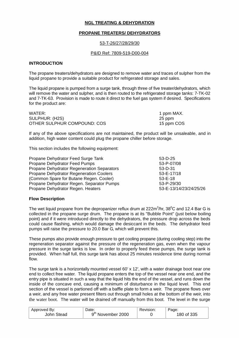
Approved By:John Stead
Date:9th November 2000
Revision:0
Page:180 of 335
NGL TREATING & DEHYDRATION
PROPANE TREATERS/ DEHYDRATORS
53-T-26/27/28/29/30
P&ID Ref: 7809-519-D00-004
INTRODUCTION
The propane treaters/dehydrators are designed to remove water and traces of sulpher from theliquid propane to provide a suitable product for refrigerated storage and sales.
The liquid propane is pumped from a surge tank, through three of five treater/dehydrators, whichwill remove the water and sulpher, and is then routed to the refrigerated storage tanks: 7-TK-02and 7-TK-63. Provision is made to route it direct to the fuel gas system if desired. Specificationsfor the product are:
WATER: 1 ppm MAX.SULPHUR: (H2S) 25 ppmOTHER SULPHUR COMPOUND: COS 15 ppm COS
If any of the above specifications are not maintained, the product will be unsaleable, and inaddition, high water content could plug the propane chiller before storage.
This section includes the following equipment:
Propane Dehydrator Feed Surge Tank 53-D-25Propane Dehydrator Feed Pumps 53-P-07/08Propane Dehydrator Regeneration Separators 53-D-31Propane Dehydrator Regeneration Coolers 53-E-17/18(Common Spare for Butane Regen. Cooler) 53-E-18Propane Dehydrator Regen. Separator Pumps 53-P-29/30Propane Dehydrator Regen. Heaters 53-E-13/14/23/24/25/26
Flow Description
The wet liquid propane from the depropanizer reflux drum at 222m3/hr, 380C and 12.4 Bar G iscollected in the propane surge drum. The propane is at its "Bubble Point" (just below boilingpoint) and if it were introduced directly to the dehydrators, the pressure drop across the bedscould cause flashing, which would damage the desiccant in the beds. The dehydrator feedpumps will raise the pressure to 20.0 Bar G, which will prevent this.
These pumps also provide enough pressure to get cooling propane (during cooling step) into theregeneration separator against the pressure of the regeneration gas, even when the vapourpressure in the surge tanks is low. In order to properly feed these pumps, the surge tank isprovided. When half full, this surge tank has about 25 minutes residence time during normalflow.
The surge tank is a horizontally mounted vessel 60’ x 12’, with a water drainage boot near oneend to collect free water. The liquid propane enters the top of the vessel near one end, and theentry pipe is situated in such a way that the liquid hits the end of the vessel, and runs down theinside of the concave end, causing a minimum of disturbance in the liquid level. This endsection of the vessel is partioned off with a baffle plate to form a weir. The propane flows overa weir, and any free water present filters out through small holes at the bottom of the weir, intothe water boot. The water will be drained off manually from this boot. The level in the surge
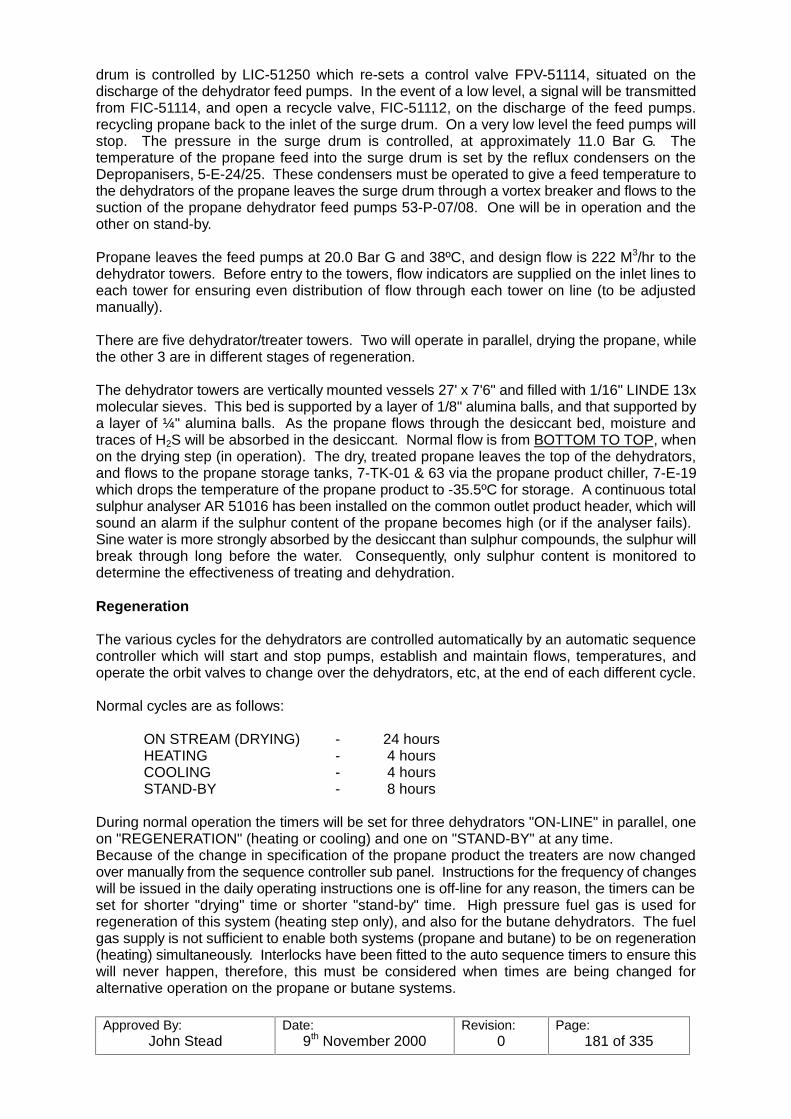
Approved By:John Stead
Date:9th November 2000
Revision:0
Page:181 of 335
drum is controlled by LIC-51250 which re-sets a control valve FPV-51114, situated on thedischarge of the dehydrator feed pumps. In the event of a low level, a signal will be transmittedfrom FIC-51114, and open a recycle valve, FIC-51112, on the discharge of the feed pumps.recycling propane back to the inlet of the surge drum. On a very low level the feed pumps willstop. The pressure in the surge drum is controlled, at approximately 11.0 Bar G. Thetemperature of the propane feed into the surge drum is set by the reflux condensers on theDepropanisers, 5-E-24/25. These condensers must be operated to give a feed temperature tothe dehydrators of the propane leaves the surge drum through a vortex breaker and flows to thesuction of the propane dehydrator feed pumps 53-P-07/08. One will be in operation and theother on stand-by.
Propane leaves the feed pumps at 20.0 Bar G and 38ºC, and design flow is 222 M3/hr to thedehydrator towers. Before entry to the towers, flow indicators are supplied on the inlet lines toeach tower for ensuring even distribution of flow through each tower on line (to be adjustedmanually).
There are five dehydrator/treater towers. Two will operate in parallel, drying the propane, whilethe other 3 are in different stages of regeneration.
The dehydrator towers are vertically mounted vessels 27' x 7'6" and filled with 1/16" LINDE 13xmolecular sieves. This bed is supported by a layer of 1/8" alumina balls, and that supported bya layer of ¼" alumina balls. As the propane flows through the desiccant bed, moisture andtraces of H2S will be absorbed in the desiccant. Normal flow is from BOTTOM TO TOP, whenon the drying step (in operation). The dry, treated propane leaves the top of the dehydrators,and flows to the propane storage tanks, 7-TK-01 & 63 via the propane product chiller, 7-E-19which drops the temperature of the propane product to -35.5ºC for storage. A continuous totalsulphur analyser AR 51016 has been installed on the common outlet product header, which willsound an alarm if the sulphur content of the propane becomes high (or if the analyser fails). Sine water is more strongly absorbed by the desiccant than sulphur compounds, the sulphur willbreak through long before the water. Consequently, only sulphur content is monitored todetermine the effectiveness of treating and dehydration.
Regeneration
The various cycles for the dehydrators are controlled automatically by an automatic sequencecontroller which will start and stop pumps, establish and maintain flows, temperatures, andoperate the orbit valves to change over the dehydrators, etc, at the end of each different cycle.
Normal cycles are as follows:
ON STREAM (DRYING) - 24 hoursHEATING - 4 hoursCOOLING - 4 hoursSTAND-BY - 8 hours
During normal operation the timers will be set for three dehydrators "ON-LINE" in parallel, oneon "REGENERATION" (heating or cooling) and one on "STAND-BY" at any time. Because of the change in specification of the propane product the treaters are now changedover manually from the sequence controller sub panel. Instructions for the frequency of changeswill be issued in the daily operating instructions one is off-line for any reason, the timers can beset for shorter "drying" time or shorter "stand-by" time. High pressure fuel gas is used forregeneration of this system (heating step only), and also for the butane dehydrators. The fuelgas supply is not sufficient to enable both systems (propane and butane) to be on regeneration(heating) simultaneously. Interlocks have been fitted to the auto sequence timers to ensure thiswill never happen, therefore, this must be considered when times are being changed foralternative operation on the propane or butane systems.
Approved By:John Stead
Date:9th November 2000
Revision:0
Page:182 of 335
Heating Step
There are six regeneration heaters. They will operate in series of three when heating, i.e. 53-E-13/14/23 will be in service in series and heating, while 53-E-26/25/24 are on stand-by, or vice-versa.
Fuel gas is taken from the HP main header at 20.3 Bar G and 38ºC. The heaters will raise thetemperature to 316ºC with 55.2 Bar G steam. The regeneration gas flow is monitored andcontrolled by FIC-51120 at 8,000 NM3/hr, and is situated before the heaters.
The regeneration gas temperature is controlled by a split range controller, TIC-51312 "A" and"B". The "A" valve (3-way) is on the main regeneration gas flow situated at the inlet to theregeneration gas heaters. This will control the relevant amount of gas flowing through or by-passing the heater. When the by-pass port is closed (all flow through the heater), the "B" valve,which controls a flow of 55.2 Bar G steam from the heater to the 5.2 Bar G steam system willopen, allowing more stem to pass through the heater, therefore heating up the gas quicker. Once the temperature is raised to the set point (316º) the "B" valve will close and the "A" valvewill then control the temperature by allowing more or less through the by-pass.
The hot regeneration gas will flow to the TOP of the dehydrator, and join the normal outlet lineand flow DOWN through the bed, picking up the moisture and H2S from the desiccant.
The wet regeneration gas exits from the BOTTOM of the dehydrator, and flows to theregeneration coolers. The temperature of the gas is monitored at the common outlet line fromthe dehydrators by TR-51311. This temperature must be maintained above 258ºC in order toremove all traces of H2S from the desiccant, or the bed capacity for treating will be decreasedfor the next drying step.
There are two regeneration gas coolers, 53-E-17 and 18.53-E-17 will be in operation for thepropane system, and 53-E-18 is a common spare for both the propane and butane systems. Both are designed to run on a continuous basis while in operation. They have motor driven fans,forcing air through a radiator-type table bundle. Adjustable louvres are fitted on top which canreduce or increase the amount of air forced between the bundle tubes, allowing control over theoutlet temperature. Design temperature of the outlet is 38ºC. The adjustable louvres are autooperated by remote control with TIC-51329 "A" for 53-E-18 and "B" for 53-E-31. The controlsare situated in the NGL Control Room.
High and low temperature indicators are fitted in the outlet bin and will indicate in the NGLControl Room. Regeneration gas then flows to the regeneration separator.
The regeneration separator, 53-D-31 is a vertically mounted vessel, 25' x 6'7", with a demisterpad fitted near the top section. The gas enters the side and flows up through the pad and exitsfrom the top. Any liquid will adhere to the pad, and when the droplets become large enough, willdrop to the base of vessel. Level glasses and level indicators are fitted to the vessel, andhigh/low levels will alarm in the NGL Control Room. A separate level indicator controller, LIC-51257, is fitted, which will control the discharge flow from the pumps when the level is within itsrange. The level will also actuate "extra high" "extra low" switches to start and stop the separatorpumps 53-P-29/30. Propane liquid will be pumped with these pumps from the separator backto the inlet line of the dehydrator feed surge tank and join the normal flow again. One pump willbe in operation and one held as stand-by. Any water which may collect in the separator will bedrained off manually. The sour regeneration gas will exit from the top and return to the HP fuelgas header under pressure control with PIC-51398. Design conditions at this point are 8,000NM3/hr, 38ºC at 17.9 Bar G.
Approved By:John Stead
Date:9th November 2000
Revision:0
Page:183 of 335
Cooling Step
After a bed has been fully heated, the regeneration gas flow is stopped. Liquid propane is takenfrom the discharge header of the dehydrator feed pumps (2" line), through FIC-51121, which willcontrol the flow of cooling propane at 10M3/hr to the BOTTOM of the dehydrator. It will then jointhe normal inlet line and flow UP through the bed, cooling the desiccant. Propane vapours andliquid will exit from the top and will flow via the regeneration beds to the regeneration separator. All liquid propane is then pumped back to the feed surge tank via the separator pumps.
The cooling liquid propane flow rate is low enough that there is no danger of fluidizing a bedwhen the propane vaporises, as it will during the first part of the cooling step. If the flow rate istoo high, fluidizing could occur and would damage the desiccant due to the friction created.
During the cooling step, the temperature of the regeneration separator is also important. If thetemperature rises much above the design of 38ºC, an excessive amount of water could be re-cycled back to the feed surge tank. If it is too low, then the water could freeze and plug up theregeneration cooler. Therefore, the temperature must be checked regularly, particularly duringa cooling step. The TIC-51329 will indicate and alarm in the NGL Control Room. Initial setpoints for the alarms are recommended as follows:
HIGH - 41ºC (105ºF)LOW - 10ºC (50ºF)
Original Start Up
Purging of Air: Before any equipment can be started, wither from having been down formaintenance purposes, or for the original start-up, all air must be purged from the piping towers.Following is a suggested approach to that problem.
Original Start Up
1. Make a temporary tie-in off the nitrogen system into the Trtr. Feed Surge Tank.2. Have all trtr tower isolating valves blocked.3. Admit nitrogen to the surge tank, preferably through the 2" spool piece provided on the
bottom of the vessel.4. Displace the air in the tank by bleeding the vessel at all bleeder points, such as gauge
glasses, and also the 3" temporary tanker loading line. (Remove clapper in check valve,but make certain it is replaced afterwards).
5. After tests have been made, and the air content is down to an acceptable level, open upthe suction to the charge pump and displace air out the pump case bleeders. o thestand by pump likewise.
6. Next, open up the inlet to one tower, and bleed through the bleeder valves provided onthe relief valve setting. Do all towers in this manner until clear.
7. Now start concentrating on the regeneration gas lines by opening the regeneration gasinlet to the tower inlet lines one at a time, and bleeding off at the regeneration gas inletto the tower inlet lines one at a time, and bleeding off at the regeneration gas heaters. Clear on through the heaters one at a time by clearing through the bleeders on theregeneration gas temperature control valve.
8. After this line is clear, repeat the same exercise on the regeneration gas line from the topof the towers.
9. Block in the bleeders on the temperature control valve, and begin clearing the lines tothe regeneration gas coolers, Regeneration gas separators, and on through the pumps.
Approved By:John Stead
Date:9th November 2000
Revision:0
Page:184 of 335
As stated above, this is just a suggested procedure, and other routes of nitrogen purge can befigured out. The main idea, however, is to make sure all piping and vessels have been purged.In some cases only parts of the treater may have been subjected to maintenance, such as a bedchange, which would require only the tower to be purged before start up. Specific instructionswill be issued in any case.
Original Start Up
The following procedure assumes that the unit has been pressure tested with the necessarycorrections made, purged of air and all rotating equipment and instruments checked out. Alltowers are blocked in.
1. Fill towers 1 through 4 and the product line to storage with liquid propane. (Towers 26,27, 28 and 29). This can be done by opening the outlet and inlet valves on one bed ata time and checking at the one inch bleeder on the outlet of each tower for liquid. Thepropane product back pressure control valve located at the storage area should be setat 17.5 Bar G (225 psig) to insure that cooling propane can be delivered to theregeneration separator, 53-D-31.
2. After filling the vessels, close the inlet manually operated block valve on towers, 2, 3 and4.
3. Set the automatic valve sequencing controller to the start of the on stream step for Tower1. Start propane through Tower 1 at a flow rate of 29.4M3/hr. (At least). The flowthrough the individual towers must never be less than this rate.
4. Open the block valves on Tower 5 and start regeneration of Tower 5. Make sure theautomatic valve sequencer is on "Automatic".
5. Open outlet block valve on Tower 4 to place it on stand-by.
6. If after 8 hours the flow rate is below 58.8M3/hr., place Tower 3 on stream and close theinlet block valve on Tower 2.
7. If after 16 hours the flow rate is below 58.8M3/hr. place Tower 3 on stream and close theinlet block valve on Tower 2.
8. As soon as the flow rate is above 58.8M3/hr. two towers may be placed on stream inparallel. If the flow rate is above 88.2M3/hr. the three towers may be placed on stream.
For further details pertaining to the operation of the "Automatic Valve Sequencer", see write-upat the end of this section.
Valve Sequence Controller
Propane & Butane Treaters
Introduction
The propane and butane treaters treat the top and bottom products of the depropaniserrespectively to remove any hydrogen sulphide and moisture from the streams.
Each treater comprises five vessels, 53-T-26/27/28/29 and 30 for the butane treater and 53-T-33/34/35/36 and 37 and for the butane treater. The vessels are referred to as ’bed 1’ ’bed 2’ ’bed3’ ’bed 4’ and ’bed 5’ for each treater in these instructions. (Refer to logic diagrams 5212 and

Approved By:John Stead
Date:9th November 2000
Revision:0
Page:185 of 335
5214 drawing number 7809.55J81-252 and 254).
The sequence controller (UC51024) is designed to switch the beds of each treater automaticallythrough their draining and regeneration sequences. It is designed so that only one of the tenbeds can be regenerated at any one time. At any one time a bed can be:-
a) Drying with product inlet and outlet valves open and regeneration valves closed.b) Hot regenerating with product inlet and outlet valves closed, regeneration valves open
and hot gas passing through the heater down through the beds.c) Cooling with the product inlet and outlet valves closed, regeneration valves open with
cooling liquid from the surge tank being passed through up the beds. The regenerationgas is shut off during cooling.
d) Idling with the product outlet valve open and the product inlet valve and regenerationvalves closed.
The bed may also be taken out of service with all the product and regeneration valves closed.The process requires that at any one time three beds on each treater are drying. The remainingbeds will be idling or regenerating. Only one bed may be regenerated at a time.
The regeneration of a bed will immediately follow its drying period. The operating sequence isdrying, hot regeneration, cooling, idling, drying, hot regeneration, cooling, idling, drying, hotregeneration, etc. (See logic diagrams 4213 and 5215 drawing numbers 7809-552J81-253 and255). Regeneration is achieved by passing heated regeneration time is fixed at 8 hours. (4hours hot regeneration and 4 hours cooling). The idling time is dependant on the drying timeand is adjusted automatically.
Provision is made for the removal of any bed from service operation on the other beds. In thissituation the remaining beds will continue with drying and regeneration periods unchanged butthe idling time will be reduced automatically. The cabinet housing the sequence controller islocated behind the control room panel (See Fig. Nos. 5-10 to 5-12). Two operator control units,one for each treater are mounted remotely in the control panel. (See Fig. Nos. 5-13 and 5-14).
In the automatic mode the controller maintains the correct sequence of operation by opening andclosing the product, regeneration and routing valves. The unit monitors the position of all valvesto ensure that each step of the sequence is done correctly. The status of each valve is displayedcontinuously on the graphic panel.
Any discrepancy between te actual valve position and that required for correct operation willsuspend the sequence and initiate an alarm. The state of each bed e.g. ’drying’ ’cooling’ etc. isalso indicated on the graphic panel. The sequence of operation under normal conditions isgiven later in this instruction.
The operator control units permit the operator to change the operation from automatic to manual,open and close any valve and to remove a train from service as follows:-
a. Any valve can be opened or closed by selecting the valve number on the thumbwheelswitch and pressing the ’open’ or ’close’ button, as appropriate. The valve position willbe indicated on the graphic panel.
b. The temperature control valves on the regeneration gas heater can be closed orcontrolled by the output of the temperature controller by pressing the appropriate button.
On start up it is necessary to preset the control valves on both treaters into one of fiveoperational patterns whilst the unit is in manual control prior to switching to automatic. Theseoperational patterns are shown on Fig. 5.1.
Approved By:John Stead
Date:9th November 2000
Revision:0
Page:186 of 335
If it is required to remove a bed from service the right hand selector switch must indicate that bedand the ’out’ button are pressed. The effects of removing a bed from service are shown in Figs.5.3 to 5.7 inclusive, at various times within the sequence. When removed from service all valvesassociated with the out of service train will be closed. They can be operated locally withoutaffecting the auto-sequence. A bed can be returned to service by pressing the ’in’ button at anytime. The beds will automatically re-enter the sequence but only at their correctly appointedtime. (See Fig. 5.8). This is because the position of each bed within the sequence relative tothe other beds is always the same.
If a valve is operated locally whilst the sequence controller is in the ’Auto’ position the sequencewill automatically suspend and an alarm will be initiated.The sequence control unit is fed from three power sources
a. 24v DC from the battery systemb. 110v DC from the battery systemc. 110v AC from the static inverter.
In the event of a failure of either or both of the DC supplies, the sequence controller will ceaseto function. As all the valves fail closed on power failure which for process considerations is notpracticable a separate solenoid valve has been fitted on to the air header supplying the valvesof each treater which in the event of poor failure will vent the air out of the header. This willensure that all valves remain in the position they enhoued prior to the poor supply failure. In theevent of failure of the 100 volts AC supply, which is only used to drive the timing mechanism,then the sequence will stop and hold the valves in the position they were at prior to the failure. On return to normal operation following failure of the DC power supplies it is necessary to followthe start up procedure. However, return of the AC supply will automatically restart the sequence. All the control valves except the temperature control valves are tight shut-off valves (orbit)powered by a double acting pneumatic diaphragm actuator. They are each fitted with a 4-portsolenoid valve, open and closed limit switches, restrictor, lock-up valve, lever operator pneumaticvalve and handwheel. Before placing the system in automatic operation it is necessary toensure that all handwheels are in neutral and that the lever operated valve s are in the normalposition.
The temperature control system on the regeneration gas heater has two control valves. Onlythe steam valve is operated by the sequence controller via a solenoid valve. A 3-way controlvalve is controlled by the output of the gas temperature controller during hot regeneration andwill open when the gas temperature required cannot be achieved by the usual steam supply.
The operation of the sequence controller is described in detail in this section. Reference shouldalso be made to the associated circuit diagrams at the back of the section..Propane Treater
Normal Operating Sequence
1. Time 0 Hrs. (&40 Hrs) Open XPV.51111 Liquid Inlet 53-T-262. Time 0 Hrs. (&40 Hrs) Close XPV.51131 Cooling Liquid3. Step 1 Complete and Close XPV 51119 Liquid Inlet 53-T-28
Step 45 Complete Close XPV 51122 Liquid Outlet 53-T-284. Step 2 Complete Close XPV 51116 Regen. Outlet 53-T-27
Close XPV 51117 Regen. Inlet 53-T-275. Step 4 Complete Open XPV 51118 Liquid Outlet 53-T-276. Step 4 Complete Open XPV 51132 Gas Routing Valve
Close XPV 51133 Liquid Routing Valve7. Step 6 Complete Open XPV 51120 Regen. Outlet 52-T-28
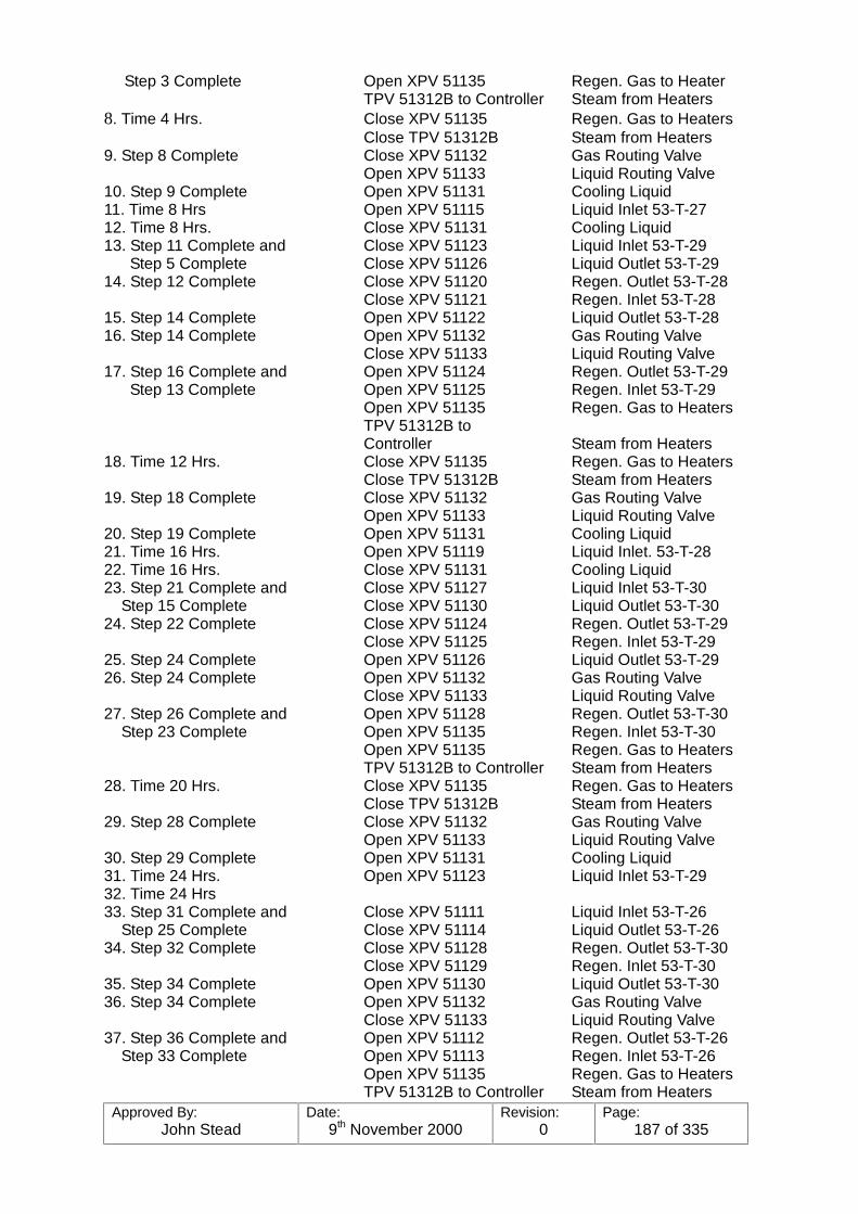
Approved By:John Stead
Date:9th November 2000
Revision:0
Page:187 of 335
Step 3 Complete Open XPV 51135 Regen. Gas to HeaterTPV 51312B to Controller Steam from Heaters
8. Time 4 Hrs. Close XPV 51135 Regen. Gas to HeatersClose TPV 51312B Steam from Heaters
9. Step 8 Complete Close XPV 51132 Gas Routing ValveOpen XPV 51133 Liquid Routing Valve
10. Step 9 Complete Open XPV 51131 Cooling Liquid11. Time 8 Hrs Open XPV 51115 Liquid Inlet 53-T-2712. Time 8 Hrs. Close XPV 51131 Cooling Liquid13. Step 11 Complete and Close XPV 51123 Liquid Inlet 53-T-29 Step 5 Complete Close XPV 51126 Liquid Outlet 53-T-2914. Step 12 Complete Close XPV 51120 Regen. Outlet 53-T-28
Close XPV 51121 Regen. Inlet 53-T-2815. Step 14 Complete Open XPV 51122 Liquid Outlet 53-T-2816. Step 14 Complete Open XPV 51132 Gas Routing Valve
Close XPV 51133 Liquid Routing Valve17. Step 16 Complete and Open XPV 51124 Regen. Outlet 53-T-29 Step 13 Complete Open XPV 51125 Regen. Inlet 53-T-29
Open XPV 51135 Regen. Gas to HeatersTPV 51312B toController Steam from Heaters
18. Time 12 Hrs. Close XPV 51135 Regen. Gas to HeatersClose TPV 51312B Steam from Heaters
19. Step 18 Complete Close XPV 51132 Gas Routing ValveOpen XPV 51133 Liquid Routing Valve
20. Step 19 Complete Open XPV 51131 Cooling Liquid21. Time 16 Hrs. Open XPV 51119 Liquid Inlet. 53-T-2822. Time 16 Hrs. Close XPV 51131 Cooling Liquid23. Step 21 Complete and Close XPV 51127 Liquid Inlet 53-T-30 Step 15 Complete Close XPV 51130 Liquid Outlet 53-T-3024. Step 22 Complete Close XPV 51124 Regen. Outlet 53-T-29
Close XPV 51125 Regen. Inlet 53-T-2925. Step 24 Complete Open XPV 51126 Liquid Outlet 53-T-2926. Step 24 Complete Open XPV 51132 Gas Routing Valve
Close XPV 51133 Liquid Routing Valve27. Step 26 Complete and Open XPV 51128 Regen. Outlet 53-T-30 Step 23 Complete Open XPV 51135 Regen. Inlet 53-T-30
Open XPV 51135 Regen. Gas to HeatersTPV 51312B to Controller Steam from Heaters
28. Time 20 Hrs. Close XPV 51135 Regen. Gas to HeatersClose TPV 51312B Steam from Heaters
29. Step 28 Complete Close XPV 51132 Gas Routing ValveOpen XPV 51133 Liquid Routing Valve
30. Step 29 Complete Open XPV 51131 Cooling Liquid31. Time 24 Hrs. Open XPV 51123 Liquid Inlet 53-T-2932. Time 24 Hrs33. Step 31 Complete and Close XPV 51111 Liquid Inlet 53-T-26 Step 25 Complete Close XPV 51114 Liquid Outlet 53-T-2634. Step 32 Complete Close XPV 51128 Regen. Outlet 53-T-30
Close XPV 51129 Regen. Inlet 53-T-3035. Step 34 Complete Open XPV 51130 Liquid Outlet 53-T-3036. Step 34 Complete Open XPV 51132 Gas Routing Valve
Close XPV 51133 Liquid Routing Valve37. Step 36 Complete and Open XPV 51112 Regen. Outlet 53-T-26 Step 33 Complete Open XPV 51113 Regen. Inlet 53-T-26
Open XPV 51135 Regen. Gas to HeatersTPV 51312B to Controller Steam from Heaters
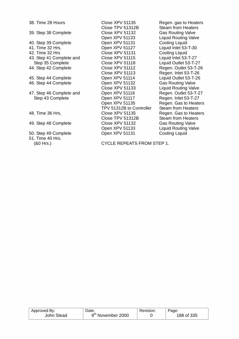
Approved By:John Stead
Date:9th November 2000
Revision:0
Page:188 of 335
38. Time 28 Hours Close XPV 51135 Regen. gas to HeatersClose TPV 51312B Steam from Heaters
39. Step 38 Complete Close XPV 51132 Gas Routing ValveOpen XPV 51133 Liquid Routing Valve
40. Step 39 Complete Open XPV 51131 Cooling Liquid41. Time 32 Hrs. Open XPV 51127 Liquid Inlet 53-T-3042. Time 32 Hrs Close XPV 51131 Cooling Liquid43. Step 41 Complete and Close XPV 51115 Liquid Inlet 53-T-27 Step 35 Complete Close XPV 51118 Liquid Outlet 53-T-2744. Step 42 Complete Close XPV 51112 Regen. Outlet 53-T-26
Close XPV 51113 Regen. Inlet 53-T-2645. Step 44 Complete Open XPV 51114 Liquid Outlet 53-T-2646. Step 44 Complete Open XPV 51132 Gas Routing Valve
Close XPV 51133 Liquid Routing Valve47. Step 46 Complete and Open XPV 51116 Regen. Outlet 53-T-27 Step 43 Complete Open XPV 51117 Regen. Inlet 53-T-27
Open XPV 51135 Regen. Gas to HeatersTPV 51312B to Controller Steam from Heaters
48. Time 36 Hrs. Close XPV 51135 Regen. Gas to HeatersClose TPV 51312B Steam from Heaters
49. Step 48 Complete Close XPV 51132 Gas Routing ValveOpen XPV 51133 Liquid Routing Valve
50. Step 49 Complete Open XPV 51131 Cooling Liquid51. Time 40 Hrs. (&0 Hrs.) CYCLE REPEATS FROM STEP 1.

Approved By:John Stead
Date:9th November 2000
Revision:0
Page:189 of 335
BUTANE TREATER
NORMAL OPERATING SEQUENCE
1. Time 0 Hrs. Close XPV 51162 Regen. Gas to Heaters (& 0 Hrs.) Close TPV 51331B Steam from Heaters2. Step 1 Complete Close XPV 51158 Gas Routing Valve
Open XPV 51159 Liquid Routing Valve3. Step 2 Complete Open XPV 51160 Cooling Liquid4. Time 4 Hrs. Open XPV 51137 Liquid Inlet 53-T-335. Time 4 Hrs. Close XPV 51160 Cooling Liquid6. Step 4 Complete Close XPV 51145 Liquid Inlet 53-T-35 & Step 48 Complete Close XPV 51148 Liquid Outlet 53-T-357. Step 5 Complete Close XPV 51142 Regen. Outlet 53-T-34
Close XPV 51143 Regen. Inlet 53-T-348. Step 7 Complete Open XPV 51144 Liquid Outlet 53-T-349. Step 7 Complete Open XPV 51158 Gas Routing Valve
Close XPV 51159 Liquid Routing Valve10. Step 9 Complete Open XPV 51146 Regen. Outlet 53-T-35 & Step 6 Complete Open XPV 51162 Regen. Inlet 53-T-35
Open XPV 51162 Regen. Gas to HeatersTPV 51331B to Controller Steam from Heaters
11. Time 8 Hrs. Close XPV 51162 Regen. Gas to HeatersClose TPV 51331B Steam from Heaters
12. Step 11 Complete Close XPV 51158 Gas Routing ValveOpen XPV 51159 Liquid Routing Valve
13. Step 12 Complete Open XPV 51160 Cooling Liquid14. Time 12 Hrs. Open XPV 51141 Liquid Inlet 53-T-3415. Time 12 Hrs. Close XPV 51160 Cooling Liquid16. Step 14 Complete Close XPV 51149 Liquid Inlet 53-T-36 & Step 8 Complete Close XPV 51152 Liquid Outlet 53-T-3617. Step 15 Complete Close XPV 51146 Regen. Outlet 53-T-35
Close XPV 51147 Regen. Inlet 53-T-3518. Step 17 Complete Open XPV 51148 Liquid Outlet 53-T-3519. Step 17 Complete Open XPV 51158 Gas Routing Valve
Close XPV 51159 Liquid Routing Valve20. Step 19 Complete Open XPV 51150 Regen. Outlet 53-T-36 & Step 16 Complete Open XPV 51151 Regen. Inlet 53-T-36
Open XPV 51162 Regen. Gas to HeatersTPV 51331B to Controller Steam from Heaters
21. Time 16 Hrs. Close XPV 51162 Regen. Gas to HeatersClose TPV 51331B Steam from Heaters
22. Step 21 Complete Close XPV 51158 Gas Routing ValveOpen XPV 51159 Liquid Routing Valve
23. Step 22 Complete Open XPV 51160 Cooling Liquid24. Time 20 Hrs. Open XPV 51145 Liquid Inlet 53-T-3525. Time 20 Hrs. Close XPV 51160 Cooling Liquid26. Step 24 Complete Close XPV 51153 Liquid Inlet 53-T-37 & Step 18 Complete Close XPV 51156 Liquid Outlet 53-T-3727. Step 25 Complete Close XPV 51150 Regen. Outlet 53-T-36
Close XPV 51151 Regen. Inlet 53-T-3628. Step 27 Complete Open XPV 51152 Liquid Outlet 53-T-3629. Step 27 Complete Open XPV 51158 Gas Routing Valve
Close XPV 51159 Liquid Routing valve

Approved By:John Stead
Date:9th November 2000
Revision:0
Page:190 of 335
30. Step 29 Complete Open XPV 51154 Regen. Outlet 53-T-37 & Step 26 Complete Open XPV 51155 Regen. Inlet 53-T-37
Open XPV 51162 Regen. Gas to HeatersTPV 51331B to Controller Steam from Heaters
31. Time 24 Hrs. Close XPV 51162 Regen. Gas to HeatersClose TPV 51331B Steam from Haters
32. Step 31 Complete Close XPV 51158 Gas Routing ValveOpen XPV 51159 Liquid Routing Valve
33. Step 32 Complete Open XPV 51160 Cooling Liquid34. Time 28 Hrs. Open XPV 51149 Liquid Inlet 53-T-3635. Time 28 Hrs. Close XPV 51160 Cooling Liquid36. Step 34 Complete Close XPV 51137 Liquid Inlet 53-T-33 & Step 28 Complete Close XPV 51140 Liquid Outlet 53-T-3337. Step 35 Complete Close XPV 51154 Regen. Outlet 53-T-37
Close XPV 51155 Regen. Inlet 53-T-3738. Step 37 Complete Open XPV 51156 Liquid Outlet 53-T-3739. Step 37 Complete Open XPV 51158 Gas Routing Valve
Close XPV 51159 Liquid Routing Valve40. Step 39 Complete Open XPV 51138 Regen. Outlet 53-T-33 & Step 36 Complete Open XPV 51139 Regen. Inlet 53-T-33
Open XPV 51162 Regen. Gas to HeatersTPV 51331B to Controller Steam from Heaters
41. Time 32 Hrs. Close XPV 51162 Regen. Gas to HeatersClose TPV 51131B Steam from Heaters
42. Step 41 Complete Close XPV 51158 Gas Routing ValveOpen XPV 51159 Liquid Routing Valve
43. Step 42 Complete Open XPV 51160 Cooling Liquid44. Time 36 Hrs. Open XPV 51153 Liquid Inlet 53-T-3745. Time 36 Hrs. Close XPV 51160 Cooling Liquid46. Step 44 Complete Close XPV 51141 Liquid Inlet 53-T-34 & Step 38 Complete Close XPV 51144 Liquid Outlet 53-T-3447. Step 45 Complete Close XPV 51138 Regen. Outlet 53-T-33
Close XPV 51139 Regen. Inlet 53-T-3348. Step 47 Complete Open XPV 51140 Liquid Outlet 53-T-3349. Step 47 Complete Open XPV 51158 Gas Routing Valve
Close XPV 51159 Liquid Routing Valve50. Step 49 Complete Open XPV 51142 Regen. Outlet 53-T-34 & Step 46 Complete Open XPV 51143 Regen. Inlet 53-T-34
Open XPV 51162 Regen. Gas to HeatersTPV 51331B to Controller Steam from Heaters
51. Time 40 Hrs. (& 0 Hrs.) CYCLE REPEATS FROM STEP 1
Approved By:John Stead
Date:9th November 2000
Revision:0
Page:191 of 335
5. SEQUENCE CONTROLLER FOR PROPANE AND BUTANE TREATERS-CABINET UC51024
5.1 General Description
The sequence controller consists of solid state circuit modules mounted on standardcards in racks together with relays and other electromechanical devices, mounted withina two-bay steel enclosure UC 51024, and two separate control sub-panels.
The racks are mounted on swing frames which allows access to the rear of the cardsockets and to the rear of the cabinet.
Connection to plant equipment is via screw-clamp terminals situated within the rear ofthe enclosure, entry to which is by top and bottom entry gland plates.
The logic circuits are connected to the screw-clamp terminals through plugs and socketsadjacent to the terminals. This enables the logic to be disconnected from the plantswitches and solenoids, and connected to the simulator (see Part IV) for testing andfault-finding.
The propane and butane circuits may be electrically isolated by means of push-buttonson the swing frame.
The logic circuits have been broken down into blocks to facilitate description, and thepropane circuits operate independently of the butane circuits with the exception of thetiming logic which is common. The sequences for the two treaters are the same, but thebutane sequence ’lags’ the propane sequence by four hours.
This means that only one bed is either on cold regeneration or hot regeneration at anytime.
5.2 Operational Description-Cabinet UC 51024
5.2.1 Start Up and Normal Operation
Before applying the supply to the circuits of wither treater the AUTO/MANUALswitches on the sub-panels should be set to MANUAL.
The START push-button for propane may bow be operated, but at this point intime all plant solenoids will remain de-energised. It is now possible to operate thepropane plant manually from the propane sub-panel.
Similarly the START push-button for butane may also be operated, to allow thebutane plant to be controlled manually from the butane sub-panel.
Valves, TPV 51312B (propane) and TPV 51331B (butane) may be opened orclosed by operating the appropriate push-buttons on the sub-panels.
Valves XPV 51111 to XPV 51133 and XPV 51135 may be operated by selectingthe last two digits of the valve number on the propane sub-panel thumbwheelswitches and then operating the OPEN or CLOSE push-button to the left of thethumbwheel switches. The valve selected will remain in the state chosen eventhough other valves may be selected.
Similarly, valves XPV 51137 to XPV 51156, XPV 51158 to XPV 51160 and XPV51162 may be operated from the butane sub-panel.
Approved By:John Stead
Date:9th November 2000
Revision:0
Page:192 of 335
If it is required to operate the plant in AUTO, it is first necessary to set all propanevalves manually to one of five start points. These five points are shown in Fig.5.1.
The rotary switch on the propane sub-panel headed BED TO START ONREGENERATION AT START OF AUTO SEQUENCE should be set to thecorresponding position. The propane AUTO push-button may now be operatedand the propane plant will continue to operate automatically according to thesequence shown in Fig, 5.1, and the manual controls will be rendered ineffective.
A similar procedure should be carried out for butane using the butane sub-panelcontrols. However, since the butane sequence ’lags’ the propane sequence byfour hours of the propane sequence. As the time lag is set automatically thebutane AUTO push-button may be operated at any time within the first four hoursof the propane sequence.
Fig 5.1 shows a sequence where propane entered service at start point 4 andbutane at start point 2. Any start point between 1 and 5 in each case ispermissible.
In Fig. 5.1 the beds are shown as drying, idling or regenerating.
During drying, the LIQUID INLET and LIQUID OUTLET valves only are open.
During idling the LIQUID OUTLET valve only is open.
During regeneration the REGEN OUTLET and REGEN INLET valves only areopen.
For the first four hours of regenerating the steam valve is open.
The valves are designated as follows (X)V preceeds all valve numbers).
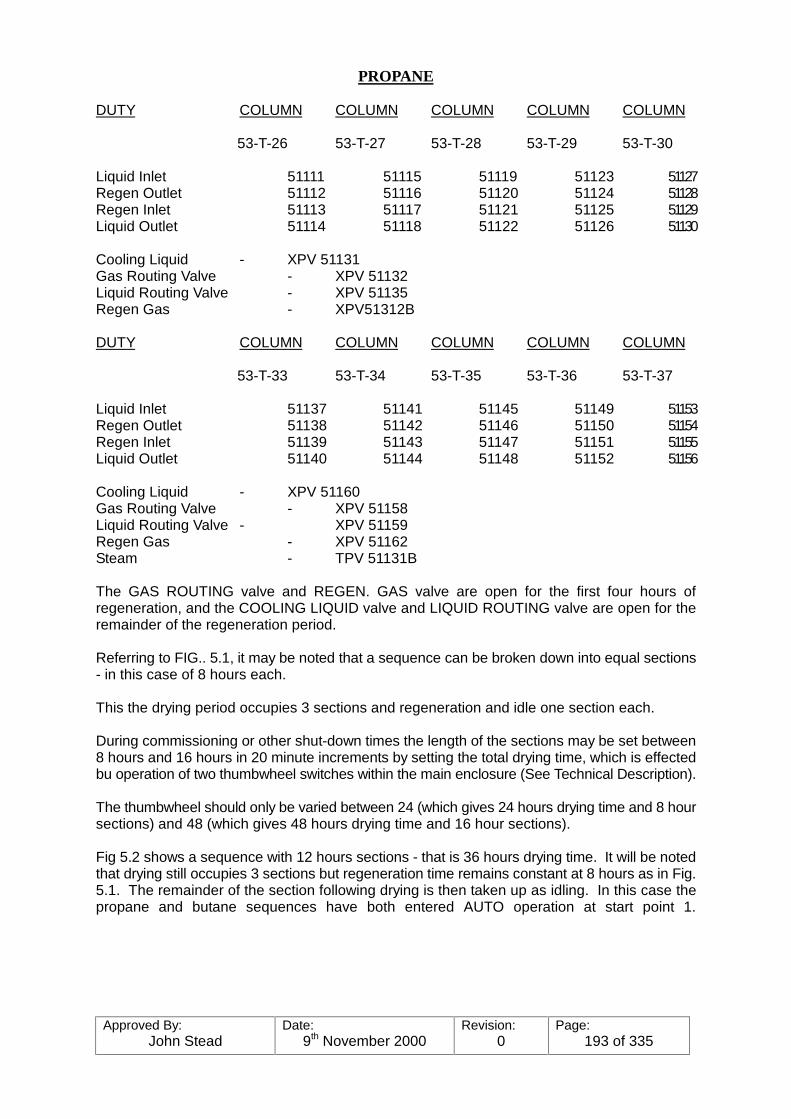
Approved By:John Stead
Date:9th November 2000
Revision:0
Page:193 of 335
PROPANE
DUTY COLUMN COLUMN COLUMN COLUMN COLUMN
53-T-26 53-T-27 53-T-28 53-T-29 53-T-30
Liquid Inlet 51111 51115 51119 51123 51127Regen Outlet 51112 51116 51120 51124 51128Regen Inlet 51113 51117 51121 51125 51129Liquid Outlet 51114 51118 51122 51126 51130
Cooling Liquid - XPV 51131Gas Routing Valve - XPV 51132Liquid Routing Valve - XPV 51135Regen Gas - XPV51312B
DUTY COLUMN COLUMN COLUMN COLUMN COLUMN
53-T-33 53-T-34 53-T-35 53-T-36 53-T-37
Liquid Inlet 51137 51141 51145 51149 51153Regen Outlet 51138 51142 51146 51150 51154Regen Inlet 51139 51143 51147 51151 51155Liquid Outlet 51140 51144 51148 51152 51156
Cooling Liquid - XPV 51160Gas Routing Valve - XPV 51158Liquid Routing Valve - XPV 51159Regen Gas - XPV 51162Steam - TPV 51131B
The GAS ROUTING valve and REGEN. GAS valve are open for the first four hours ofregeneration, and the COOLING LIQUID valve and LIQUID ROUTING valve are open for theremainder of the regeneration period.
Referring to FIG.. 5.1, it may be noted that a sequence can be broken down into equal sections- in this case of 8 hours each.
This the drying period occupies 3 sections and regeneration and idle one section each.
During commissioning or other shut-down times the length of the sections may be set between8 hours and 16 hours in 20 minute increments by setting the total drying time, which is effectedbu operation of two thumbwheel switches within the main enclosure (See Technical Description).
The thumbwheel should only be varied between 24 (which gives 24 hours drying time and 8 hoursections) and 48 (which gives 48 hours drying time and 16 hour sections).
Fig 5.2 shows a sequence with 12 hours sections - that is 36 hours drying time. It will be notedthat drying still occupies 3 sections but regeneration time remains constant at 8 hours as in Fig.5.1. The remainder of the section following drying is then taken up as idling. In this case thepropane and butane sequences have both entered AUTO operation at start point 1.
Approved By:John Stead
Date:9th November 2000
Revision:0
Page:194 of 335
5.2.2 Taking a Bed Out of Service
Once ion service the propane and butane sequences operate independentlyalthough the length of each section of operation is not independent. This thefollowing applies equally to the propane or butane sequences.
During normal AUTO operation on bed only may be out of service at any onetime. Interlocking ensures that another bed may not be taken out when the bedout push-button has been operated.
To take a bed out of service the sub-panel rotary switch designated BED TO BETAKEN OUT OF SERVICE is set at the appropriate position. The push-buttonto the right of the rotary switch is then operated.
The sequence immediately following the action of taking a bed out will dependon the point at which the bed is taken out. Figs. 5-3 to 5-7 show the resultingsequences when Bed 3 is taken out during each of its section of operation. Forthe purposes of discussion the section immediately following drying will bereferred to as regeneration even though the first 8 hours only are taken up theregeneration.
The drying time is 30 hours in Figs. 5-3 to 5-7.
5.2.3 Returning a Bed to Service
This may be accomplished by setting the rotary switch of para. 5.2.2 to theappropriate position and operating the push-button.
The push-button may be operated at any time, however the bed will not bereturned to service until the point is reached in the sequence at which it would beentering its regeneration stage. This is shown more clearly in Fig. 5-8.
Instrument Air Failure: All switching valves controlled by the automatic valvesequencer control will stay in the position they were in at the time of the failure,but the Regeneration Separator Pump must be shut down because its outercontrol will shut off. Shut down the Feed Pumps, 519-670-07 or 08 to stop theminimum flow back to the feed tank. All control valves will close, therebystopping the propane, and regeneration flow to and from the Trtr. The bleedsteam from the heaters will also close.
Electrical Failure: All motors will stop. This will get the Regeneration Gas CoolerFans, Feed Pumps and Separator Pumps.
All switching valves controlled by the automatic valve sequencer control willremain in the position they were in at the time the failure occurred.
Block in the steam leaving the Regeneration Gas Heater, otherwise there will bea continuous loss of 55 bar g steam into the 17.2 bar g steam system.
Sulpher Analyser: A continuous total sulphur analyser has been installed (AR-51016) on the treater outlet which will sound an alarm, (AR-51016), if the sulphurcontent of the propane gets too high. This alarm will sound long before any watergets through.
Approved By:John Stead
Date:9th November 2000
Revision:0
Page:195 of 335
NGL TREATING & DEHYDRATIONPROPANE DEHYDRATOR/TREATERS
PUMPS/COMPRESSORS
EQUIP. NO. DESCRIPTION TYPE DRIVE CAPACITY DISCH.PRESS.SUB-STATION
DEOILER fractionator
5-T-08
HISTORY
Under the original design concepts this column was to be used as an iso-butane de-propanizer,but shortly after the initial plant start up it became apparent that the column duty changed. It ishowever worth pointing out it would be a fairly easy job to return the column duty back to itsoriginal state if it were so desired.
The following write up is therefore for the column as we now operated i.e. a deoiler.
1. Purpose and Services:
The purpose of the deoiler is to remove the heavier C5 (pentane) fraction from the normalbutane product ex the C4 splitter column bottoms.
The system includes the fractionating tower, overhead condensing system (air cooledcondensing coils), accumulator and pumps.
a. Feed - the normal feed to the deoiler is the pentane drag stream from the bottomof the butane splitter containing iso and normal pentane and normal butane. Thefeed enters the column at a temperature of60-65�&�DW�RQ�RI�WZR�inlet points either tray 28 or tray 34.
b. Overhead Product - the overhead product is normal butane which is to be addedto the main normal butane product from tray 5 (sidedraw) of the Butane Splitter,and the combined streams are then sent to storage.
c. Bottom Product - the bottom product is the iso and normal pentane fraction whichties in to the combined stabilised crude rubdown and then to Greatham storage.
2. Process Equipment and Flow Arrangement
a. The feed is pressured from the base of the butane splitter via a 4" line througha fin fan cooler 5-E-18 (NB this cooler now has the fans shut-down as it wasoriginally a rundown cooler when the column was run as an iso-butanedepropaniser. The feed flow is controlled by FIC 51141 and from here it passesto the column and enters via feed points on the 28th or 34th trays.
The reboiler is heated with a steam supply at 3.4 bar g (50 psig) and 148ºC(298ºF). The steam pressure reduces to about 2.1 bar g (30 psig) across thesteam control valve PPV-51139 on its way to the heating element.
Approved By:John Stead
Date:9th November 2000
Revision:0
Page:196 of 335
Control System
a. Feed to the column is on flow control, FPV-51141
Steam to the reboiler is on flow control, FPV-51199 reset by Distillation ColumnControl, or tray temperature control TIC 51368 from either the 5th or 45th traylevel. Condensate is on condensate accumulator liquid level control resettingcontrol valve PLV-51290 in the discharge of the condensate pump. Minimumflow protection is provided for the pumps.
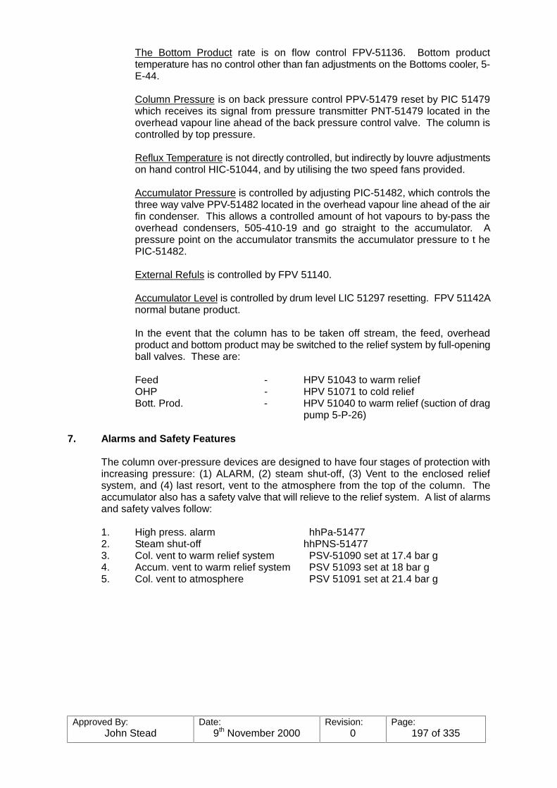
Approved By:John Stead
Date:9th November 2000
Revision:0
Page:197 of 335
The Bottom Product rate is on flow control FPV-51136. Bottom producttemperature has no control other than fan adjustments on the Bottoms cooler, 5-E-44.
Column Pressure is on back pressure control PPV-51479 reset by PIC 51479which receives its signal from pressure transmitter PNT-51479 located in theoverhead vapour line ahead of the back pressure control valve. The column iscontrolled by top pressure.
Reflux Temperature is not directly controlled, but indirectly by louvre adjustmentson hand control HIC-51044, and by utilising the two speed fans provided.
Accumulator Pressure is controlled by adjusting PIC-51482, which controls thethree way valve PPV-51482 located in the overhead vapour line ahead of the airfin condenser. This allows a controlled amount of hot vapours to by-pass theoverhead condensers, 505-410-19 and go straight to the accumulator. Apressure point on the accumulator transmits the accumulator pressure to t hePIC-51482.
External Refuls is controlled by FPV 51140.
Accumulator Level is controlled by drum level LIC 51297 resetting. FPV 51142Anormal butane product.
In the event that the column has to be taken off stream, the feed, overheadproduct and bottom product may be switched to the relief system by full-openingball valves. These are:
Feed - HPV 51043 to warm reliefOHP - HPV 51071 to cold reliefBott. Prod. - HPV 51040 to warm relief (suction of drag
pump 5-P-26)
7. Alarms and Safety Features
The column over-pressure devices are designed to have four stages of protection withincreasing pressure: (1) ALARM, (2) steam shut-off, (3) Vent to the enclosed reliefsystem, and (4) last resort, vent to the atmosphere from the top of the column. Theaccumulator also has a safety valve that will relieve to the relief system. A list of alarmsand safety valves follow:
1. High press. alarm hhPa-514772. Steam shut-off hhPNS-514773. Col. vent to warm relief system PSV-51090 set at 17.4 bar g4. Accum. vent to warm relief system PSV 51093 set at 18 bar g5. Col. vent to atmosphere PSV 51091 set at 21.4 bar g
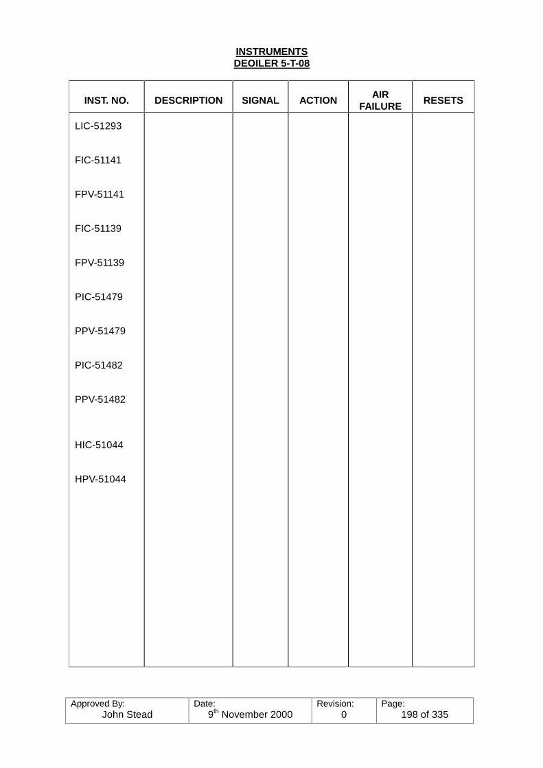
Approved By:John Stead
Date:9th November 2000
Revision:0
Page:198 of 335
INSTRUMENTSDEOILER 5-T-08
INST. NO. DESCRIPTION SIGNAL ACTION AIRFAILURE RESETS
LIC-51293
FIC-51141
FPV-51141
FIC-51139
FPV-51139
PIC-51479
PPV-51479
PIC-51482
PPV-51482
HIC-51044
HPV-51044
Approved By:John Stead
Date:9th November 2000
Revision:0
Page:199 of 335
IIINGL REFRIGERATION, PRODUCT CHILLING,
STORING AND LOADING
OPERATORS’ MANUAL
A. INTRODUCTION
The purpose of the NGL Refrigeration System is to provide the liquid feed and refluxnecessary for the ultimate production, storage and loading of the ethane product, as wells the chilling, storage and loading of iso-butane, normal butane and propane products.
The system utilises two types of refrigerants; propane and ethane, each having its ownequipment and functions, nut utilising a cascading effect between the two in some cases.
Three gas turbine driven three-stage compressors are used in the propane refrigerationsystem, three steam driven compressors in the ethane refrigeration system, threeelectrically driven compressors in the ethane tank pressure maintenance and threeelectrically driven compressors in the propane tank pressure maintenance system.
The process utilises heat exchange between the product to be chilled and the refrigerantused - whether propane or ethane. The refrigerant is pressured from the refrigerantsurge drum (ethane or propane) to the various exchangers and equipment involve,where it exchanges heat with the process to be chilled. The vapours created from thisexchange are picked up by the refrigerant surge drum to be circulated again foradditional use. The heat is removed and eventually dispersed via the propanerefrigeration system, condenser coils, where heat is exchanged with air.
Briefly, the propane refrigeration system makes possible the cooling required tocondense the de-ethaniser columns reflux, chill the demethaniser columns feed, chill thepropane product and help maintain the propane storage tanks, condense all ethanerefrigerant vapours, chill the ethane product before going into storage, chill the iso-butane, normal butane, before going to refrigerated storage, and maintain therefrigerated storage.
The ethane refrigeration system is used as the coolant to provide reflux for thedemethaniser tower and for chilling the ethane product for refrigerated storage. It alsois used for re-condensing the boil-off vapours from the ethane storage tank.
The NGL loading systems have been computerised for automatic or remote loading ofeither cold or hot product. Ethane loading, however, is not computerised and must bedone under manual control.
Additional details of the refrigeration system, refrigerated NGL storage system andproduct loading is presented in the following discussion.
METHANOL INJECTION POINTS
No. 1 De-C2 Twr. O.H. line upstream of PPV-51133 1No. 1 De-C2 Twr. O.H. to O.H. condensers. One to each core 3C3 refrig. to No. 1 De-C2 O.H. condensers. One to each core 3C3 refrig. to No 1 De-C2 T.S.D. upstream of LPV-51074 1No. 2 De-C2 Twr. O.H. upstream of PPV-51152 1No. 2 De-C2 Twr. O.H. to O.H. condensers. One to each core 3C3 refrig. to No.
Approved By:John Stead
Date:9th November 2000
Revision:0
Page:200 of 335
B. PROPANE REFRIGERATION SYSTEM
1. Description
The N.G.L. unit includes two types of fractionators which cannot normally use air or waterfor condensing reflux for separation of Methane and Ethane from the N.G.L. stream.
Pure Ethane cannot be liquified above its critical temperature of 32ºC and pure Methanecannot be liquified above its critical temperature of -82ºC. The condensers for the twoDe-Ethaniser columns and the De-Methaniser column, operate at -12ºC and-73ºCrespectively.
The N.G.L. unit produces Ethane, Propane, Isobutane and normal Butane as saleableproducts, which are stored under refrigerated temperature and atmospheric pressure. Storage refrigeration temperature varies according to the product.
Ethane requires a temperature of -89ºC; Propane -43ºC; Isobutane -12ºC; and normalButane -1ºC.
It can be seen from the previous statement, that refrigeration must be provided at varioustemperature levels ranging from -1ºC to -89ºC.
It was decided to use two refrigerants at Teesside, one level to operate between -1ºC to-43ºC and the second between -43ºC to -89ºC.
Some type of refrigeration system had to be designed as it was not possible, using airor water directly, to get these low temperatures, hence the choice of Propane andEthane. Propane selected as the high temperature range refrigerant to operate between-1ºC to 43ºC and Ethane as low temperature refrigerant to operate between -43ºC to -89ºC.
The entire refrigeration system will operate at five temperature/pressure ranges tomaximise efficiency of the units.
Each refrigerant is handled by separate units and will be known as the (PropaneRefrigerant) and (Ethane Refrigerant) Systems.
PROPANE REFRIGERATION
To get a better understanding of how the system will operate, let us first consider anddefine what the unit must do.
a. Condense reflux at 12ºC on De-Ethaniser Columns.b. Chill De-Methaniser column feed from 10ºC to -35ºC.c. Chill Ethane product from De-Ethaniser columns from -4ºC to -35ºC.d. Chill Propane product from 38ºC to -35ºC.e. Maintain Propane product in refrigerated Storage Tanks at -46ºC.f. Chill Isobutane product from 38ºC to -12ºC.g. Maintain Isobutane product in Storage Tank at -12ºC.h. Chill normal Butane from 38ºC to 1ºC.i. Maintain normal Butane in Storage Tank at -1ºC.j. Condense all Ethane refrigerant at -35ºC.

Approved By:John Stead
Date:9th November 2000
Revision:0
Page:201 of 335
To sustain the plant for continuous 100% operation, three 50% compressor units wereinstalled, with each compressor unit rated at 9,315 BHP, having the same capacities andcontrol systems built into them. It is expected that two compressors will be in serviceunder normal design-load conditions.
The propane refrigeration system will operate at three pressure and temperature ranges.High stage refrigerant will operate at 4.8 Bar G and 7.2ºC. Intermediate stage refrigerantwill operate at 1.7 Bar G and -16ºC. Low stage refrigerant will operate at 0.1 Bar G and-40ºC.
Suction to the compressors 706-160-10/11/12, at the level stated above is supplied fromthe various users in the system, collected into individual headers and introduced to thecompressors.
The combined discharge vapours at a temperature of 70ºC and pressure of 13.5 Bar Gare condensed in thirty (30) air fan coolers 706-410-20 at a temperature of 38C. On thirdof the fans having two speed motors, these being staggered, every third set having a twospeed motor.
Exact control is not necessary, any numbers of fans can be run to achieve a temperatureor read across the cooling bundles of 29ºC to 38ºC on condensing. A suitable numberof fans should be run to condense the compressors at various load conditions.
The condensed vapours are routed to two surge tanks 706-950-35/46 which will normallyoperate in parallel at a pressure of 13 Bar G.
Provision is made to take one tank our of service should it become necessary formaintenance.
Refrigerant make-up is routed to both surge tanks directly from the Propane product lineahead of all the chillers. Normal make-up is expected to be about 10bls/day, any suddenincrease could indicate a leaking relief valve.
The automatic shut-down valve for the refrigeration system is situated at the outlet ofsurge tanks in the 20" line leading to the common header that supplies the various usersin the system. This is a positive shut-off valve and will close automatically if all thecompressors are shut-down, to prevent leakage from filling flash drums and flash tanksin the system.
At this point it may be better to deal with the compressor recycle system separately.
Prior to going to the air fan coolers, provision is made to route from 0-100% of thecompressors discharge flow to the recycle system.
This flow is split under flow control to the appropriate recycle drum depending oncompressor suction conditions at each stage, i.e. H.S. - I.S. - L.S., the amount of eachflow being governed by the anti-surge control settings built into the system.
Recycle flow is controlled to provide and maintain a minimum flow through each of thethree compression stages.
Each recycle drum has individual temperature, pressure and level controls incorporated,and is designed to produce generated vapours going to their respective suctionscrubbers hot enough to prevent liquid condensing and slugging into the compressors.The recycle drums are fitted with a fractionation type tray plate, hot vapours from thecompressors are introduced via a sparge type header beneath this plate, liquid Propaneunder level control from the surge tank is fed to the drum above the tray at the top of the
Approved By:John Stead
Date:9th November 2000
Revision:0
Page:202 of 335
vessel. This arrangement provides intimate contact of the liquid and vapours peculatingthe vapours through the tray to give even temperature control on the vapour outlet.
Should a high level condition arise, the level control will override temperature andpressure controllers until conditions return to normal.

Approved By:John Stead
Date:9th November 2000
Revision:0
Page:203 of 335
One of the surge tanks is supplied with a vent condenser 706-410-31 for removal of lightends that will tend to build up in the surge tanks, this will be evident by a slow build upin pressure while the temperature of the surge tanks remains virtually the same.
Provision is made to route Propane refrigerant from the outlet of the surge tanks via anH.I.C. to control the flow through the coil in the condenser. Vapour flow exit thecondenser should be such that a temperature differential of about 4ºC is obtainedbetween the surge tank temperature and the condenser vapour outlet temperature.Ethane vapour exit the condenser is under H.I.C. control and routed to Ethane storage.
Propane vapours, exit the coil, flow to the compressor suction scrubbers. Provision ismade to direct this flow to whichever suction is desirable, it is important therefore, toensure that excessive liquid refrigerant is not used as this may result in unvapourisedliquid winding up in the compressor suction scrubbers.
Flow to the condenser will automatically be shut-off if all three compressors shut-downand the automatic shut-down valve closes.
Refrigerant flow exit the surge tanks via the main 20" header is now split and routed tothe various users. For the purpose of this description they have been separated into fourgroups.
First of these users is the Iso and Normal Butane chiller. Both of these products arechilled from 38ºC to 12ºC in separate exchangers but, in the same vessel, known as theH.S. Propane Evaporator 706-410-18.
This vessel is designed to operate with an evaporating pressure of 4.8 Bar G andtemperature of 7.2ºC.
Refrigerant make-up to the vessel is under level control, the vapourised liquid beingvented to the high stage suction header of the compressors. In addition to chilling duty,the H.S. evaporator acts as a reservoir for Propane refrigerant feed to the interstageevaporator, 706-410-17.
The intermediate stage evaporator contains three exchanger coils, Isobutane chiller,Normal Butane chiller, Normal Butane tank heat leak recycle chiller. All these productsare chilled from 12ºC to -12ºC with the evaporator working at a temperature of -17º andan evaporating pressure of 1.7 Bar G. Refrigerant flow is on level control, this vesselacting as a reservoir also for the low stag evaporator, 706-410-16. Vapourised liquidbeing vented to the interstage suction header of the compressors.
The low stage evaporator contains a single coil, for chilling Isobutane recycle from thestorage tank heat leak to maintain a tank temperature of -12ºC, the vessel operates withan evaporating pressure of 0.10 Bar G and temperature of -40ºC. Propane refrigerantflow is on level control and vapours are routed to the low stage suction header of thecompressors.
Components heavier than Propane will tend to build up in this vessel, and will be seenby a slight, but gradual rise in temperature of the evaporator liquid. When this occurs thevessel should be drained of heavy ends to accumulator tank 706-950-49 and pressuredto the Propane Storage Tank.
Facilities have been provided to bypass both refrigerant and product sides of the highstage and interstage evaporators, so the equipment can be taken out of service formaintenance. If these facilities are used it may be necessary to vent some product fromthe storage tank.
Approved By:John Stead
Date:9th November 2000
Revision:0
Page:204 of 335
The next take-off from the 20" header supplies the Propane product and tank vapourcondenser 706-410-19 which is a plate type unit, this condenser contains three coils forthe refrigerant, the product and tank vapours flowing between a series of plates.This exchanger utilises all three stages of refrigeration. Refrigerant flows to the highstage flash or thermosyphon drum 706-950-13 under level control, the refrigerant flowingthrough the exchanger coils and vapourised, returning to the drum where the vapour isvented to the compressor suction header. The high stage is designed to operate at 4.8Bar G and 7.2ºC.
Refrigerant from the high stage flash drum is letdown under level control to the interstagedrum 706-950-14 which operates at 1.7 Bar G and -16ºC, refrigerant from the interstagedrum is letdown in the same manner to the low stage drum 706-950-15 which operatesat 0.1 Bar G and -40ºC. Both of these loops operate in the same way as the high stage,the generated vapours being routed to their respective suction headers.
Propane product and tank vapours enter the condensor at 38ºC and 27ºC respectively,flowing through the refrigerant coils from high stage through to low stage in that order.Outlet product temperatures are 35.6ºC and product and condensed vapours are routedto storage.
This condenser is enclosed in an insulated box and provision is made for a continuousN2 purge to prevent build up of hydrocarbon gasses.
Each flash drum can be bypassed and taken out of service if required for maintenancerepairs, heavy ends that may build up in the low pressure drum can be drained to anaccumulator tank and pressured to the Propane storage tank. The flash drums must beoperated at the design levels otherwise loss of efficiency will result. Low levels will giveinsufficient heat transfer and result in higher tank vapour and product temperatures.
Alcohol injection points have been provided to dissolve water plugs that may occur.
The next propane refrigerant take-off supplies the Ethane product chillers and Ethanerefrigerant condensers.
Refrigerant is flashed down from 12.9 Bar G via level control to the high stage flash drum706-950-10 which operates at 4.8 Bar G and 7ºC. Vapours from this drum are routed tothe compressor high stage suction header. It is expected that approximately 20% of feedwill flash off in this vessel.
Liquid refrigerant from the high stage flash drum flows to the interstage evaporator 706-410-09 via level control the temperature and pressure being letdown across this valveto 1.7 Bar G and -16ºC.
The interstage evaporator contains on e chiller coil, known as the Ethane product chillerVapours from the evaporator are routed to the interstage compressor suction header.
Ethane product enters the chiller at -3.3ºC and is chilled to -12ºC.
Refrigerant leaves the interstage evaporator and enters the low stage flash orthermosyphon drum 706-950-09 under level control which also lets the pressure andtemperature down to 0.1 Bar G and -40ºC. Vapours from the flash drum are routed tothe low stage suction header of the compressor.
The refrigerant liquid is routed to the plate type exchanger unit 706-410-08 and flow isthrough the coil in the bottom section of the exchanger. The top section of theexchanger is used as a vapour economiser, utilising the high stage and low stagevapours from the Ethane refrigerant system to chill the circulating Ethane refrigerant.
Approved By:John Stead
Date:9th November 2000
Revision:0
Page:205 of 335
High stage Ethane vapours enter the chiller box at -59ºC, low stage vapours at -77ºC,and leave at 26.7ºC. Ethane refrigerant enters the exchanger at 38ºC.
The chilled Ethane refrigerant passes down to the bottom section of the exchangerwhere it is further cooled by the low stage propane refrigerant coil and leaves at atemperature of -35.6ºC.
In addition to the above mention duties an extra plate exchanger is incorporated in thebottom section which further chills Ethane product exit the Ethane product chiller from-12ºC to -35.6ºC.
In N2 purge is supplied with this unit for a constant purge of hydrocarbon vapours fromthe insulated box around this exchanger.
The final take-off from the main 20" header supplies the overhead condensers for thetwo De-Ethaniser columns and the De-Methaniser feed chiller.
Refrigerant flows to the high stage flash drum 706-950-12 under level control whichreduces the pressure and temperature across the valve to the operating pressure of 4.8Bar G and -16ºC temperature.
Vapours from the flash drum are routed to the high stage suction header of thecompressors about 22% of inlet flow.
There are two outlets for liquid flow associated with this flash drum. One supplies thetwo interstage flash or thermosiphon drums 521-950-01/02 on the De-Ethaniser columnsoverheads, the other outlet is routed to the interstage flash drum 706-950-11 whichsupplies the low stage refrigerant drum 521-950-03 connected to the De-Methaniser feedchiller, 75% flows to De-Ethaniser, 25% flows to De-Methaniser.
Flow to the De-Ethaniser system is under level control, the level control valves operatingto maintain operating levels in the two interstage thermosyphon drums reducing thepressure and temperature across the valve to 1.7 Bar G and -16ºC.
Vapours from both vessels are routed to the compressor interstage suction header. Refrigerant is circulated through the overheads condensers chilling the overheadvapours from 2.2ºC and condensing them at the outlet temperature of -12ºC and 28 BarG pressure.
Should heavy ends build up in these drums they should be drained to accumulator TKS521-050-05/05 and heavy ends pressured to Propane storage.
Refrigerant for the De-Ethaniser feed chiller 505-410-12 is letdown to intermediate flash706-950-11 drum under level control, and will be reduced to 1.7 Bar G and -16ºC. About15% of the liquid is flashed off and routed to the interstage suction header of thecompressors. Liquid refrigerant is routed to the De-Methaniser feed chiller thermosiphondrum 521-950-03 under level control and reduced in temperature and pressure acrossthis valve to 0.1 Bar and -40ºC. Refrigerant is circulated through the feed chillerreducing feed temperature to the De-Methaniser from 9.4ºC to -35.6ºC. Vapours leavingthe drum are controlled by a T.I.C., which controls the outlet temperature of the chiller byadjusting the rate of evaporation of the refrigerant in the drum. Vapours are routed to thelow stage suction header of the compressors. Once again heavy ends that may build upare drained and pressured to the Propane storage tank via accumulator tank 521-950-07.

Approved By:John Stead
Date:9th November 2000
Revision:0
Page:206 of 335
Provision is made to bypass both the high stage and interstage flash drums supplyingthe two De-Ethaniser column refrigerants, should it be required for maintenance orotherwise.

Approved By:John Stead
Date:9th November 2000
Revision:0
Page:207 of 335

Approved By:John Stead
Date:9th November 2000
Revision:0
Page:208 of 335

Approved By:John Stead
Date:9th November 2000
Revision:0
Page:209 of 335

Approved By:John Stead
Date:9th November 2000
Revision:0
Page:210 of 335

Approved By:John Stead
Date:9th November 2000
Revision:0
Page:211 of 335

Approved By:John Stead
Date:9th November 2000
Revision:0
Page:212 of 335

Approved By:John Stead
Date:9th November 2000
Revision:0
Page:213 of 335

Approved By:John Stead
Date:9th November 2000
Revision:0
Page:214 of 335

Approved By:John Stead
Date:9th November 2000
Revision:0
Page:215 of 335

Approved By:John Stead
Date:9th November 2000
Revision:0
Page:216 of 335

Approved By:John Stead
Date:9th November 2000
Revision:0
Page:217 of 335
Approved By:John Stead
Date:9th November 2000
Revision:0
Page:218 of 335
ETHANE REFRIGERANT UNIT
1. Purpose
This unit will provide refrigerant requirements for the NGL and Storage Areas, the dutybeing split almost equally between both areas.
In the NGL Process Area, refrigerant is supplied to condense de-methaniser overheadvapours for reflux. In the Storage Area, refrigerant is required to condense ethaneproduct and re-condense storage tank heat leak vapours.
2. Unit Flow and Controls
Assume that the unit is in a "go" status, and ethane refrigerant levels are established inthe surge tank and other flash drums and vessels in the system.
Refrigerant in surge tank 7-TK-06 under normal design conditions of 8.8 Bar G and -35ºC, leaves via a 6" line at the bottom of the vessel. The automatic shutdown valve forthe "unit" HPV-71102, is situated in this line and will automatically if all compressors areshutdown, either in a planned manner or emergency trip situation.
The surge tank has a pressure control valve, PIC-71003 to vent excess vapours to thecold relief system. The instrument is panel mounted in the NGL Control Room. A HI andLO level alarm and level recorder for the surge tank are also panel mounted in the NGLControl Room.
Make up refrigerant to the unit is routed to the surge tank from the ethane product linedownstream of the product chiller, 7-E-08.
Refrigerant leaving the surge tank via the 6" line separates downstream of the automaticshutdown valve, HPV-71102, into separate 4" lines.
One stream flows to the high stage evaporate flash drum 7-D-08, supplying liquidrefrigerant to 7-E-01 cold box, for tank vapour condensing, the other stream goes to 7-TK-05 acting as a head tank for 54-D-04 (De-methaniser overhead thermosyphon drum).
Flow to both these vessels is under level control, flow to 7-D-08 via LIC-71012 and flowto 7-TK-05 via LIC 71008. Owing to the vessel being elevated and the LIC located atgrade, 7-TK-05 runs with only 0-5% level, the high level alarm now activated at 20%(there is no low level alarm on this vessel).
The pressure and temperature of the refrigerant liquid is reduced across the level controlvalves from 8.8 Bar G -35ºC to 2.95 Bar G –95ºC.
Both level controllers with HI and LO level alarm are panel mounted in the NGL ControlRoom.
Each flash drum has a pressure control valve situated on the vapour outlet lines, PIC-71001 on 7-TK-05 and PIC-71301 on 7-D-08, both controllers are panel mounted in theNGL Control Room.
Vapours from both drums are combined in a common header, flowing to the high stagesuction "drip leg" prior to entering 7-E-08, the ethane refrigerant vapour economiser,where the flashed vapours are heated from -59ºC to 26.7ºC to meet compressor suctiontemperature design conditions.
Approved By:John Stead
Date:9th November 2000
Revision:0
Page:219 of 335
Prior to entering the vapour economiser, provision is made to vent vapours to the coldrelief system via HIC-710075 valve, which is remotely operated from the NGL ControlRoom, A high pressure alarm is situated upstream of this valve and is panel mountedin the NGL Control Room also.
This control should be used only when excessive pressure build-up is experienced in thissection of the unit, and not as a variable control during normal operations i.e. loss of allcompressors and circulation through the unit for such a period of time that heat leaksfrom the atmosphere starts to vaporise the residual liquid in the system with thepossibility of lighting relief valves.
Liquid refrigerant from the high stage flash drum 7-TK-05 which serves the NGLrequirements is routed to the de-methaniser column overheads refrigerant thermosiphondrum 54-D-04 under level control via LIC-51212 which is situated near the inlet of drum54-D-04. There are two other valves situated in this section of line HPV-71187 on theoutlet of 7-TK-05 and HPC-71081 which is listed downstream of LIC-51212 on the inletof 54-D-04. All of these instruments are panel mounted in the NGL Control Room.
HPV valves 71187-51081 will give a positive shut off when closed and should beswitched to the closed position if the unit is shutdown or level control valve LIC-51212opens due to a mechanical fault. This will prevent high pressure liquid filling the de-methaniser overheads refrigerant thermosiphon drum and flooding the vapour return lineto the low stage suction of the compressors, giving rise to the possibility of tripping thecompressors due to low temperature suction conditions.
Liquid refrigerant flowing to thermosiphon drum 54-D-04 is reduced in pressure andtemperature across LIC-51212 from 2.95 Bar G -59ºC to 0.78 Bar G - 77ºC in thethermosiphon drum. Refrigerant from the bottom of the drum is routed to the plate typeexchanger 5--15 where it cools the column overhead vapours from -45ºC to -72ºC. Vapours returning to the refrigerant drum are routed to the common header for the lowstage suction of the compressors.
Liquid refrigerant from the high stage evaporator flash drum, 7-D-08, flows through themiddle section of the combined tank vapour economiser - condenser and ethaneproduce chiller 7-E-01, vapours returning to the flash drum and flowing to the combinedhigh stage suction to the compressors. Refrigerant liquid from the bottom outlet of drum7-D-08 flows under level control via LIC 71010 to the low pressure evaporator flash drum7-D-08, pressure and temperature being reduced across the level controller from 2.95Bar G at -59ºC to 0.78 Bar G at 77ºC.
The liquid refrigerant in this drum, 7-D-07, flows through the bottom section of the vapoureconomiser and produced chiller 7-E-01, vapours returning to the low stage evaporatorflash drum being routed to the low stage suction header of the compressors via PIC71002 and combine with the low pressure vapours from 54-D-04. The now combinedvapours flow to the low stage "drip leg" prior to entering the refrigerant vapoureconomiser 7-E-08, at an inlet temperature of -77ºC and leave at a temperature of26.7ºC before being routed to the compressors. Prior to entering the vapour economiserprovision is made for venting excess pressure that may occur via HIC-71076, asexplained previously on the high stage suction header.
All level and pressure controllers are panel mounted in the NGL Control Room, High andLow level alarms, high level trips and high pressure alarms are also provided.
To sustain 100% plant operation three compressors each rated at 50% capacity wereinstalled. Each compressor being driven by 55 Bar G steam turbine, having its ownindividual lube and seal oil systems.

Approved By:John Stead
Date:9th November 2000
Revision:0
Page:220 of 335
Each compressor is provided with the conventional lube and seal oil shutdown, turbineoverspeed shutdown systems. In additions there are low suction temperature trips oneach stage from the process area and high temperature trips on each discharge stageof the compressors.
Each compressor has a pressure control valve situated in the LOW and HIGH pressuresuction lines downstream of the suction valves. These are mounted in the NGL ControlRoom. In addition a pressure tapping is situated in the low stage suction of thecompressors feeding a PIC which operates the governor on the steam turbine.
The pressure controllers will be set to maintain 0.36 Bar G pressure at the low pressuresuction and 2.6 Bar G at the high pressure suction of the compressors, these controllerare left in wide open position in manual mode.
Flow from the discharge of the low stage compressor is routed through an air fan cooler,cooling the compressed vapours from 102ºC to 38ºC, where it then passes through anon return valve and combines with the high stage suction vapours. Provision is madedownstream of the air fan cooler and before the non return valve to recycle vapours tothe suction to prevent surge of the machine.
The recycle flow is governed b an FIC which monitors the discharge flow and will operatea control valve in the recycle line. Pressure and temperature compensators are providedand combine with the FIC to provide correct flow calculations. The second stage recyclevapours are controlled in the same manner as stated for the low stage vapours.
The now combined discharge vapours from each compressor are routed to a highefficiency mist extractor 7-D-36 which removed entrained seal oil in the dischargevapours.
Great importance should be attached to this vessel and a constant check on the oil levelaccumulated noted and the vessel drained to ensure as low a level present as possible.
Any oil carried over into the vapour economiser and produce chiller 7-E-08 will mostcertainly freeze out and plug the exchanger.
Vapours leaving mist extractor 7-D-36 enter the vapour economiser/product chiller (7-E-08) and are cooled in the top section by the high and low stage flashed vapours goingto the compressor suctions, they then pass downwards to the bottom section where lowstage propane refrigerant further chills them to an outlet temperature of -35.6�&��DOVRin this bottom section ethane product is chilled from -12ºC to -35.6ºC. The condensedvapours are routed to the surge tank 7-TK-06. Ethane product flowing to the tank vapoureconomiser/condenser 7-E-01 where it is further chilled to a temperature of -72ºC at theoutlet. It is further cooled by passing through a pressure control valve, PIC 71005,reducing the pressure from 15 Bar G to 25m Bar and a temperature of -96ºC.
The insulation boxes around vapour economiser/product chiller 7-E-08, and tank vapoureconomiser/product chiller 7-E-01, called cold boxes, have a N2 purge of 2m3/hr suppliedto prevent any excessive build up of hydrocarbon vapours.

Approved By:John Stead
Date:9th November 2000
Revision:0
Page:221 of 335

Approved By:John Stead
Date:9th November 2000
Revision:0
Page:222 of 335

Approved By:John Stead
Date:9th November 2000
Revision:0
Page:223 of 335
PRINCIPLE OF OPERATION
The Rotor impellers, when rotating at high speed, impart energy into the gas which is flowingthrough them. The gas enters the intake (suction) volute of the compressor and flows throughthe first stage inlet vane which directs the gas at a suitable angle axially into the "eye" of the firststage impeller at high velocity. The gas glows into an annular passage is increasing in area asgas flows through the return bend; therefore converting part of the velocity energy of the gas intopressure energy. The gas then flows round the return bend through a vented annular passagein the diaphragm and into the second stage inlet guide vane and impeller. After subsequentstages of compression the gas flows into the discharge volute of the compressor.
Due to the difference in area between the side walls of each impeller the axial thrust of the rotorassembly is towards the suction end of the compressor. In order to limit this trust to areasonable but still positive value for long thrust bearing life, a balance piston is secured to thedischarge end of the rotor shaft. A mating labyrinth type seal is secured to the discharge wall. The last stage impeller at the other side is externally piped (by means of a balance connector)to either suction or interstage gas pressure. The difference in pressure either side of the pistonproduces a thrust opposite in direction to that of the impeller.
Seal ports ’D’ (See fig 1, inner oil seals diagram) at inboard end of seal assemblies areinterconnected by a gas balance line to equalise pressure at inboard end of seals so as toensure that both HS and LS ends can be supplied by seal oil at the same pressure. Seal ports’C’ at outboard end of seals are vented to atmosphere to prevent any back pressure at the outerseal rings. Therefore, both seal assemblies in a compressor are sealing against the samepressures.
Process gas leakage into seal ports ’A’ is the actual gas pressure that has to be sealed against(seal reference pressure or gas reference) and is used to establish the required seal oil supplypressure to ports ’B’. An overhead oil storage tank is mounted with a normal level approximately15 feed above the compressor centre line to provide a head of seal oil to ports ’B’ atapproximately 5 psig above seal pressure. The gas reference pressure from the discharge endport ’A’ is externally piped to the top of the seal oil head tank to ensure a positive seal oil supplypressure to ports ’B’ at the 5 psig delta p.
Sealing oil enters ports "b" and flows between the seals rings/shaft clearance since designclearance of this ring is greater than that of the inner ring and seal port "C" is at atmosphericpressure. This oil drains from port "C" and is returned to the seal oil reservoir. The remainderof seal oil flows between the inner ring/shaft clearance into seal port "A". Since the seal oil isapproximately 5 psi above gas pressure (Seal Reference Pressure) in port "A", gas leakage ispositively prevented. The slinger configuration machined in the shaft sleeve plus a small gasflow between the inner labyrinth/shaft clearance prevents oil from entering the gas stream.
The mixture of oil and entrained gas drains from ports ’A’ into sour oil drain traps where the gasis separated from the oil. The gas is vented to either hot vent header or the compressor, lowstage suction. The oil is routed to a degassing tank prior to going back to the seal oil reservoir.
ETHANE REFRIGERATION COMPRESSOR CONTROLS
Vapours from the Ethane Refrigerant Vapour Economiser Condenser and Ethane ProductChiller, 706-410-08, (Stream 6) leave the chiller through a 16" line which is then routed to themachines 12" suction manifold.
The discharge from the low stage is routed from the machine through an air fin cooler and thenjoins into the suction line to the high stage section of the machine. Pressure here is boosted toabout 3 Bar G to get into the suction of the high stage.
Approved By:John Stead
Date:9th November 2000
Revision:0
Page:224 of 335
The high stage main suction line is an 8" line which comes off the main 12" vapour line fromstream "7" of the same chiller, 7-E-08, as did the low stage. The pressure on this line iscalculated to be about 2.75 Bar G, at 26.7ºC.
Also, in both high and low stage sections, if the vapour load decreases to a certain point arecycle flow from the discharges back to the suctions (Whichever the case may be) will beinduced through a 6" tie-over (In the low stage) and a 4" tie-over (In the high stage) which iscontrolled by FIC's which measure the flow from the individual discharges from each section. This is referred to as "Minimum Flow Recycle Control". The purpose of this is to guarantee apre-set minimum flow of vapour through each section of the machine at all times regardless ofthe load. According to the P & ID's, the minimum flow rate for the machine is:
Low stage, 3254NM3/hrHigh stage, 8496 NM3/hr

Approved By:John Stead
Date:9th November 2000
Revision:0
Page:225 of 335

Approved By:John Stead
Date:9th November 2000
Revision:0
Page:226 of 335

Approved By:John Stead
Date:9th November 2000
Revision:0
Page:227 of 335

Approved By:John Stead
Date:9th November 2000
Revision:0
Page:228 of 335
Approved By:John Stead
Date:9th November 2000
Revision:0
Page:229 of 335
ETHANE REFRIGERATION COMPRESSOR STEAM TURBINE DRIVER7-CT-04/05/06
The driver for the ethane refrigeration system compressor is a non condensing steam turbine,built by Worthington.
A non condensing turbine is one which exhausts to a pressure greater than, or equal toatmospheric pressure.
The turbine rotor is forged construction. The wheel baskets are inserted in dovetail groovesmachined in the rim of the wheel.
The rotor is carried by babbit lined bearings.
Axial location of the turbine rotor in the casing is maintained and thrust is absorbed be a singlethrust bearing located in the steam end bearing case, and operates in a continuous oil bath.
Labyrinth type packing is used in the end glands to seal the openings in the casing where theturbine shaft passes through, which reduces to a minimum leakage along the shaft.
Speed control of the turbine is effected by a Woodward type governor. The governor controlsthe steam inlet valve through a direct mechanical connection. The function of the speedgovernor system is to maintain practically constant speed regardless of load by opening orclosing the inlet steam valve to the steam nozzles. The speed governor is equipped with apneumatic receiver which acts to change the speed setting the governor is equipped with apneumatic receiver which acts to change the speed setting the governor in response to the airsignal. The speed control element of the governor is in control at all times, however, duringsuch changes.
The turbine trip system enables the turbine to be shut down in the following ways:
1. Manually2. As a result of overspeeding3. As a result of de-energising the solenoid operated dump valve
Regardless of the means by which the turbine is tripped out, the end result is the same whichis the instantaneous closing of the trip and throttle valve.
Lubricating oil is taken from the oil reservoir an supplied to the bearings under pressure by apositive displacement pump. From this pump the oil passes through the oil filter to the oil cooler. From the oil cooler the oil is supplied to the turbine bearings at a pressure maintained by theback pressure control valve located in the line. The excess oil from the control valve is drainedback to the oil tank.
Solenoid Dump Valve - The solenoid operated dump valve is mounted in a line taken from thelow oil pressure trip oil supply line. The purpose of the valve is to create an artificial low oilpressure condition when the valve is open causing the turbine to be shut down by action of thelow lube oil pressure trip.
When the unit is in operation the valve is closed and oil pressure is maintained on the low oilpressure trip bellows assembly holding the trip in its latched position. When the valve opens,oil from the low oil pressure trip bellows housing is dumped to drain. The resultant loss of oilpressure actuates the low oil pressure trip and the turbine is shut down through its trippingdevice.
Approved By:John Stead
Date:9th November 2000
Revision:0
Page:230 of 335
Speed Governor - The speed governor is driven by a governor drive shaft located in the steamend bearing case which, in turn, is driven by a worm on the turbine shaft, and a bronze gear onthe governor shaft.
Emergency Governor and Trip Mechanism - The purpose of the emergency governor is to stopthe turbine when its speed reaches a pre-determined value - usually 15% higher than itsmaximum speed.
To reset the emergency governor, close the steam valve in the steam line to the turbine, relievethe pressure in the steam chest by opening the drain valve connected to the bottom of the steamchest. Release the latch spring and raise the valve lever so that it will latch with the trip lever.
Low Oil Pressure Trip - The purpose of the low oil pressure trip is to stop the turbine when thebearing pressure drops below a safe level. It is mounted on the side of the steam end bearingcase, and consists of a spring loaded bellows acting to release a spring loaded plunger rod. When released, the plunger rod strikes a trip finger. This action causes the release of the tripthrottle valve trip lever. Upon release of the trip lever the trip throttle valve closes, shutting thesteam supply to the turbine, shutting it down.
(Turbine drive for c-2 compr.)
OPERATING INSTRUCTIONS
a. Starting the turbine.
1. Prepare the driven compressor for starting.2. Check the oil level in the main oil tank and in the speed governor.3. Check general external condition of the unit. Check to see that the solenoid valve is
closed. (Energised).4. Start auxiliary oil pump and check lube oil pressure.5. Reset the overspeed trip device.6. Open all drain in line valves from trip throttle valve, steam chest and casing.7. Slowly open exhaust line shut off valve to admit steam from exhaust header to turbine
casing for the purpose of warming up the casing. Do not impose full exhaust linepressure on casing when it is cold. If exhaust line shut-off valve is equipped with abypass line use this line for better control of steam. When casing is heated to saturationtemperature of exhaust line steam, or very nearly so, and when condensate no longershows from the drain lines, open the exhaust line shut-off valve wide open.
8. Set governor speed changer so that governor will assume control above critical speedand below normal running speed. (See Data sheet for critical speed of turbine).
9. Reset trip throttle valve.10. Open valve quickly so that a sudden rush of steam starts the rotor spinning. Adjust
throttle valve so rotor is kept rolling at a speed not to exceed 500 rpm.11. Close all drain line valves when they blow steam and no condensate.12. Listen for unusual noises which might indicate rubbing or other internal distress. If any
noises are detected the turbine should be shut down, and the trouble remedied. If suchnoises are detected the turbine should be shut down, and the trouble remedied. If suchnoises are not encountered, put gland seal system into operation as outlined. Under nocircumstances should sealing steam be admitted to packing glands when rotor isstationary. This is important!
13. Maintain the speed at maximum of 500 rpm until the rotor and casing are evenly heated. The time required for heating may vary but will be approximately one half hour. Theexperienced operator will soon become acquainted with the turbine and understand itsrequirements. During this period check bearings for overheating and check temperatureof oil leaving cooler. If this temperature exceeds 120ºF, admit cooling water to cool,otherwise wait until unit is brought up to rated speed. The temperature of the oil leaving
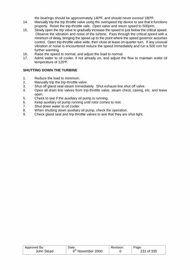
Approved By:John Stead
Date:9th November 2000
Revision:0
Page:231 of 335
the bearings should be approximately 140ºF, and should never exceed 180ºF.14. Manually trip the trip throttle valve using the overspeed trip device to see that it functions
properly. Reset the trip-throttle vale. Open valve and return speed to 500prm.15. Slowly open the trip valve to gradually increase the speed to just below the critical speed.
Observe the vibration and noise of the turbine. Pass through the critical speed with aminimum of delay, bringing the speed up to the point where the speed governor assumescontrol. Open trip-throttle valve wide, then close at lease on-quarter turn. If any unusualvibration or noise is encountered reduce the speed immediately and run a 500 rom forfurther warming.
16. Raise the speed to normal, and adjust the load to normal.17. Admit water to oil cooler, if not already on, and adjust the flow to maintain outlet oil
temperature of 120ºF.
SHUTTING DOWN THE TURBINE
1. Reduce the load to minimum.2. Manually trip the trip-throttle valve.3. Shut off gland seal steam immediately. Shut exhaust line shut off valve.4. Open all drain line valves from trip-throttle valve, steam chest, casing, etc. and leave
open.5. Check to see if the auxiliary oil pump is running.6. Keep auxiliary oil pump running until rotor comes to rest.7. Shut down water to oil cooler.8. When shutting down auxiliary oil pump, check the operation.9. Check gland seal and trip throttle valves to see that they are shut tight.
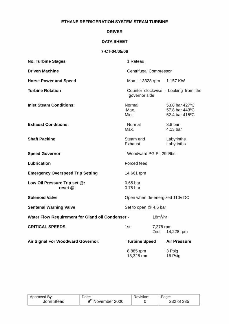
Approved By:John Stead
Date:9th November 2000
Revision:0
Page:232 of 335
ETHANE REFRIGERATION SYSTEM STEAM TURBINE
DRIVER
DATA SHEET
7-CT-04/05/06
No. Turbine Stages 1 Rateau
Driven Machine Centrifugal Compressor
Horse Power and Speed Max. - 13328 rpm 1.157 KW
Turbine Rotation Counter clockwise - Looking from thegovernor side
Inlet Steam Conditions: Normal 53.8 bar 427ºCMax. 57.8 bar 443ºC
Min. 52.4 bar 415ºC
Exhaust Conditions: Normal 3.8 barMax. 4.13 bar
Shaft Packing Steam end LabyrinthsExhaust Labyrinths
Speed Governor Woodward PG Pl, 29ft/lbs.
Lubrication Forced feed
Emergency Overspeed Trip Setting 14,661 rpm
Low Oil Pressure Trip set @: 0.65 bar reset @: 0.75 bar
Solenoid Valve Open when de-energized 110v DC
Sentenal Warning Valve Set to open @ 4.6 bar
Water Flow Requirement for Gland oil Condenser - 18m3/hr
CRITICAL SPEEDS 1st: 7,278 rpm2nd: 14,228 rpm
Air Signal For Woodward Governor: Turbine Speed Air Pressure
8,885 rpm 3 Psig13,328 rpm 16 Psig
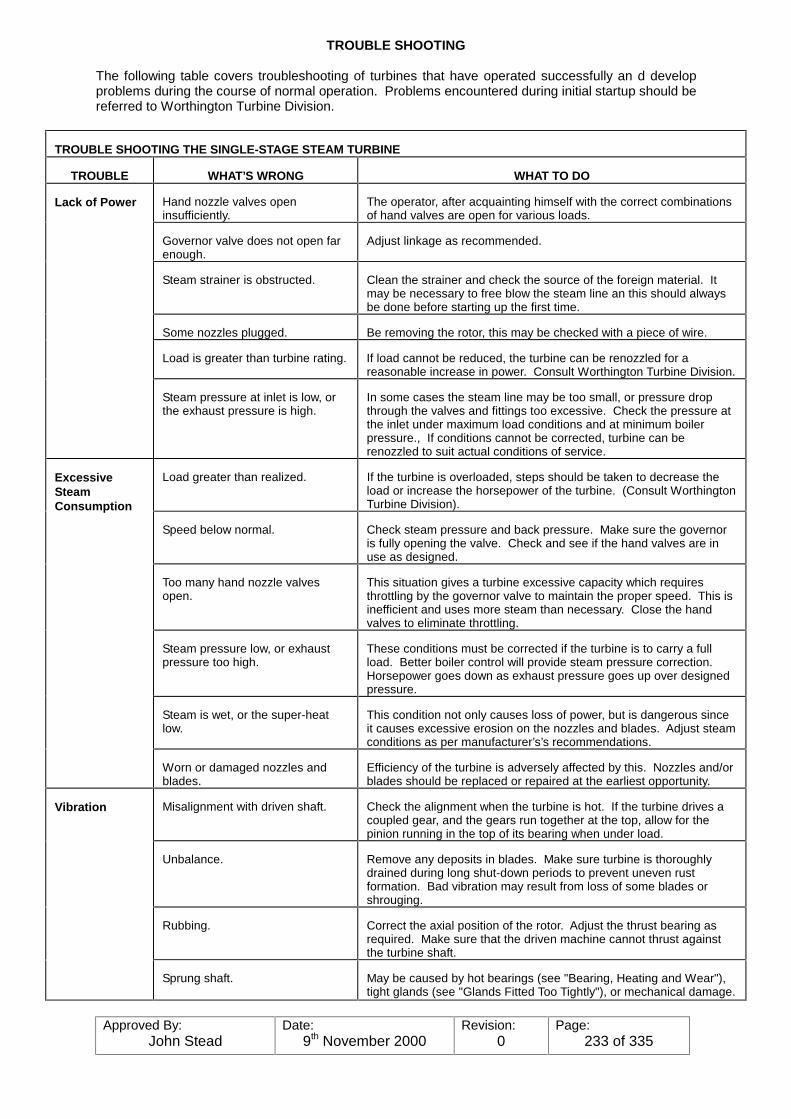
Approved By:John Stead
Date:9th November 2000
Revision:0
Page:233 of 335
TROUBLE SHOOTING
The following table covers troubleshooting of turbines that have operated successfully an d developproblems during the course of normal operation. Problems encountered during initial startup should bereferred to Worthington Turbine Division.
TROUBLE SHOOTING THE SINGLE-STAGE STEAM TURBINE
TROUBLE WHAT’S WRONG WHAT TO DO
Hand nozzle valves openinsufficiently.
The operator, after acquainting himself with the correct combinationsof hand valves are open for various loads.
Governor valve does not open farenough.
Adjust linkage as recommended.
Steam strainer is obstructed. Clean the strainer and check the source of the foreign material. Itmay be necessary to free blow the steam line an this should alwaysbe done before starting up the first time.
Some nozzles plugged. Be removing the rotor, this may be checked with a piece of wire.
Load is greater than turbine rating. If load cannot be reduced, the turbine can be renozzled for areasonable increase in power. Consult Worthington Turbine Division.
Lack of Power
Steam pressure at inlet is low, orthe exhaust pressure is high.
In some cases the steam line may be too small, or pressure dropthrough the valves and fittings too excessive. Check the pressure atthe inlet under maximum load conditions and at minimum boilerpressure., If conditions cannot be corrected, turbine can berenozzled to suit actual conditions of service.
Load greater than realized. If the turbine is overloaded, steps should be taken to decrease theload or increase the horsepower of the turbine. (Consult WorthingtonTurbine Division).
Speed below normal. Check steam pressure and back pressure. Make sure the governoris fully opening the valve. Check and see if the hand valves are inuse as designed.
Too many hand nozzle valvesopen.
This situation gives a turbine excessive capacity which requiresthrottling by the governor valve to maintain the proper speed. This isinefficient and uses more steam than necessary. Close the handvalves to eliminate throttling.
Steam pressure low, or exhaustpressure too high.
These conditions must be corrected if the turbine is to carry a fullload. Better boiler control will provide steam pressure correction. Horsepower goes down as exhaust pressure goes up over designedpressure.
Steam is wet, or the super-heatlow.
This condition not only causes loss of power, but is dangerous sinceit causes excessive erosion on the nozzles and blades. Adjust steamconditions as per manufacturer’s’s recommendations.
ExcessiveSteamConsumption
Worn or damaged nozzles andblades.
Efficiency of the turbine is adversely affected by this. Nozzles and/orblades should be replaced or repaired at the earliest opportunity.
Misalignment with driven shaft. Check the alignment when the turbine is hot. If the turbine drives acoupled gear, and the gears run together at the top, allow for thepinion running in the top of its bearing when under load.
Unbalance. Remove any deposits in blades. Make sure turbine is thoroughlydrained during long shut-down periods to prevent uneven rustformation. Bad vibration may result from loss of some blades orshrouging.
Rubbing. Correct the axial position of the rotor. Adjust the thrust bearing asrequired. Make sure that the driven machine cannot thrust againstthe turbine shaft.
Vibration
Sprung shaft. May be caused by hot bearings (see "Bearing, Heating and Wear"),tight glands (see "Glands Fitted Too Tightly"), or mechanical damage.

Approved By:John Stead
Date:9th November 2000
Revision:0
Page:234 of 335
TROUBLE WHAT’S WRONG WHAT TO DO
Loose wheels. It is extremely unusual, but may be caused by a runaway, excessivesteam temperature or shock loading.
Vibration(Continued)
Glands fitted too tightly. Tight carbon rings may cause vibration and overheating. Refer toShaft Packing instructions for proper clearance.
Badly worn or broken carbon rings. Replace with new rings. Carbon rings should have a slight clearanceon the shaft when cold, as carbon expands much less with heat thansteel.
Carbon rings fouled by dirt or scalecarried over by steam.
The rings should be free to float axially, and the down-stream face ofthe ring must seat perfectly against the smooth, true and cleansurface of the adjacent carbon ring spacer.
Leak-off line not freely open. Be sure the leak-off line cannot trap water and cause back pressure.
Excessive exhaust pressure. Packing cases are designed for a pre-determined back pressure. Excessive back pressure causes leakage, which is a common causeof water in the lubricating oil.
ExcessiveGland Leakage
Compound used to seal horizonaljoint has covered carbon rings.
When replacing carbon rings, use Turboseal compound carefully. Excessive compound may foul the carbon rings, and the surfacesagainst which they float.
Use of improper oil. Oil must be clean and of the proper viscosity. Refer to Section IIinstruction s as to the correct lubricant.
Water cooling devices provided notused; cooling water too hot.
This situation may cause a breakdown of the oil. It also will causethe thrust bearing and main bearings to overheat excessively. Eachinstallation may have different cooling water requirements. Oilshould leave the oil cooler at 120F in forced feed units, with thecooling water adjusted to give the proper temperature to the oil.
Water in the oil. This may result from gland leakage, cooler leakage, or condensationfrom the atmosphere. To minimize condensation from theatmosphere, shut off water from the oil cooler after shutting down. This should be done as soon as the turbine casing has cooledenough so excessive heat will not be transferred to the bearings. Occasionally check oil reservoirs for water, and drain off any present.
Misalignment. Misalignment is a common cause of excessive bearing wear. TheBabbitt may be cracked or broken loose as a result of te poundingfrom a misaligned shaft.
Unbalance. This is often due to deposits on buckets or wheels. In rare cases it iscaused by the loss of one or more buckets or a piece of shroug. Inspect and clean the rotating element.
Rough journal surface. Journals can be stoned if not too seriously roughened. In extremecases journals will need to be chrome plated.
Thrust from driven shafttransmitted through coupling.
Proper distance must be maintained between ends of the shaft andthe driven unit. Check this distance. make sure the coupling is freeto move laterally. The coupling can become full of dirt or sludge andnot be free to move laterally.
Excessive tension in spring typespeed changer.
The tension on the speed changer spring must be sufficient to holdthe governor lever firmly against the governor spindle correctionunder all conditions. Avoid any unnecessary loading on this springas this would impose excessive load on the thrust bearing.
Speed governor trying to close aleaking or stuck governor valve.
Leaking or stuck valve should be corrected as it constitutes a safetyhazard, besides being detrimental to the thrust bearing. Excessivewear is also impose excessive load on the thrust bearing.
Bearing,Heating andWear
Heavy slugs of water in the steam. This condition can be avoided through proper boiler control. Damage to thrust bearings and wheels will result from water slugs.

Approved By:John Stead
Date:9th November 2000
Revision:0
Page:235 of 335
TROUBLE WHAT’S WRONG WHAT TO DO
Bearing,Heating andWear(Continued)
Rough or untru thrust collars.(Shoe-Type Bearing).
Rough or untrue thrust collars on single-stage machines may causerapid wear on thrust facings of the sleeve bearings. This couldeventually increase thrust clearance at a point where the turbinewheels would rub on the guide or reversing ring. Rough or untruecollars should be replaced or repaired at the first opportunity.
No provision for exhaust pipe. A good expansion joint and proper pipe supports are needed.
Excessive steam pipe stresses. Stress can be overcome by the use of proper supports and hangers,and the use of loops or bends in the steam line. An expansion jointshould be provided for the exhaust line, adjacent to the turbine.
Turbine casing supportingmembers are hot due to poorinsulation.
Maintain insulation behind these members, but leave them open togood ventilation.
Foundations of driver and drivenmachine move.
If the turbine and driven unit are on separate foundations, anymovement will cause misalignment. If foundations aren’t adequateto hold both units, a concrete cap should be poured over both toassure operation on a similar plane.
Units Do NotStay inAlignment
Baseplates exposed to heat fromsteam pipes.
The distortion caused bu excessive heat on the baseplate maycause misalignment. Pipes should be insulated or relocated awayfrom baseplates.
A leaky governor valve, or a leaknear governor valve.
This situation should be corrected by replacing or repairinggovernor valve and seal, otherwise the turbine will continue toreceive steam even with the governor in closed position.
Governor responds slowly due toworn parts or sticking.
Free the sticking valve and inspect all pivot points in linkage forsigns of sticking or binding or excessive wear.
Speed RisesExcessivelyWith Loss ofLoad
Governor does not fully closegovernor valve.
Adjust linkage.
Sticking or excessive friction ingovernor, valve or valve stem.
Generally due to dirt, wear or mechanical damage. Clean andrepair or replace.
Lost motion so the governor valvedoesn’t always follow motion ofgovernor.
This is usually the result of excessive wear at the pivot points in thelinkage. Bearing in the linkage should be replaced, as well as thelinkage pins.
Hunting
Governor knife edges worn. These must be replaced if badly worn. There is no effective repairfor these parts.
(Same causes as "Hunting").SlowResponse
Turbine carrying very heavy load,little reserve power.
Open necessary hand valves to increase horsepower.
Improper adjustment or poorcondition of tripping mechanism,springs or latches.
The trip valve should be tested frequently. To test the valve, trip theoverspeed mechanism by hand. Make sure the trip valve closespromptly and stops the turbine.
Trip Valve
Excessive friction in trip valvespindle packing. Scaling, wear ormechanical damages in trip valveor its supports.
These serious faults should be corrected by cleaning, repairing orreplacing parts so that this important safety device can operateeffectively.
OverspeedGovernor(MechanicalShaft)
Governor does not trip at or nearthe proper speed.
Remove the governor cover and examine the Overspeed Governor. Make sure it is clean, in good order, and that the emergency weightcan be easily and freely moved in the governor cup by a smallscrew-driver or similar tool. Adjust as described in Section VI.
Test unit by actually overspeeding. If it still doesn’t trip at the properspeed, adjust the setting of the emergency governor as required.
If low oil pressure trips, solenoid trips, high back pressure trips, orsimilar devices are provided, check them at the same time.


Approved By:John Stead
Date:9th November 2000
Revision:0
Page:237 of 335
PUMPS/COMPRESSORSETHANE REFRIG.
Equip. Number Description Type Drive Capacity Disch. Press. Sub Station
7-C-01
7-C-02
7-C-03
7-C-04
7-C-05
7-C-06
7-BL-01
7-BL-02
Ethane storage tankcompressor
Ethane storage tankcompressor
Ethane storage tankcompressor
Ethane Refrig. compressor
Ethane Refrig. compressor
Ethane Refrig. compressor
Ethane tank blower
Ethane tank blower
cent
cent
cent
cent
cent
cent
cent
cent
elec
elec
elec
steamturbine
steamturbine
steamturbine
elec
elec
3300NM3/HR
3300NM3/HR
3300NM3/HR
1st stage 7467NM3/HR2nd stage 12420NM3/HR
1st stage 7467NM3/HR2nd stage 12420NM3/HR
1st stage 7467NM3/HR2nd stage 12430NM3/HR
6600NM3/HR
6600NM3/HR
10 Bar G
10 Bar G
10 Bar G
3.14 Bar
3.14 Bar
3.14 Bar
0.414 Bar
-
-
-
-
-
-

Approved By:John Stead
Date:9th November 2000
Revision:0
Page:238 of 335
Equip. Number Description Speed Criticals Overspeed Inlet Exhaust
7-CT-04
7-CT-05
7-CT-06
Steam turbine forethane refrig.comp.
Steam turbine forethane refrig.comp.
Steam turbine forethane refrig.comp.
Press.53.8 Bar
Temp. 427ºC
Press. 53.8 Bar
Temp. 427ºC
Press.53.8 Bar
Temp. 427ºC
3.88 Bar
238.8ºC
3.88 Bar
238.8ºC
3.88 Bar
238ºC

Approved By:John Stead
Date:9th November 2000
Revision:0
Page:239 of 335
EXCHANGERS
Products Shell T1 Tube T1Equip. No. Description
Shell Tube
Pressure
7-E-01 Section 1Stream 1 - 115ºC - +65ºCStream 2 - 115º - +105ºC
11.8 Bar12.0 Bar
Section 2Stream 2 - 115ºC - +105ºCStream 3 - 96ºC - +65ºCStream 4 - 96º - +65ºC
12.0 Bar30.2 Bar11.8 Bar
Tank vapoureconomiser and productchiller
Section 3Stream 2 - 115ºC - +105ºCStream 3 - 96ºC - +65ºCStream 5 - 96ºC - +65ºC
12.0 Bar30.2 Bar11.8 Bar
Section 1Stream 6 - 96ºC - +65ºCStream 7 - 95ºC - +65ºCStream 8 - 96ºC - +105ºC
11.8 Bar11.8 Bar16.0 Bar
7-E-08Ethane refrigerantvapour economiser andethane product chiller
Section 2Stream 8 - 96ºC to +105ºCStream 9 - 96ºC to +65ºCStream 10 - 96ºC to +65ºC
16.0 Bar30.2 Bar14.5 Bar
7-E-027-E-037-E-04
I.S. air coolers on 7-C-01/02/03
air ethane - - 118ºC118ºC118ºC
2.5 Bar2.5 Bar2.5 Bar
2.2 Bar2.2 Bar2.2 Bar
7-E-057-E-067-E-07
Ethane Storagecompressors air coolers
air ethane - - 10 Bar10 Bar10 Bar
9.4 Bar9.4 Bar9.4 Bar
7-E-107-E-117-E-12
Ethane refrig.compressors dischargeair coolers
air ethane - - 9.6 Bar9.6 Bar9.6 Bar
8.9 Bar8.9 Bar8.9 Bar
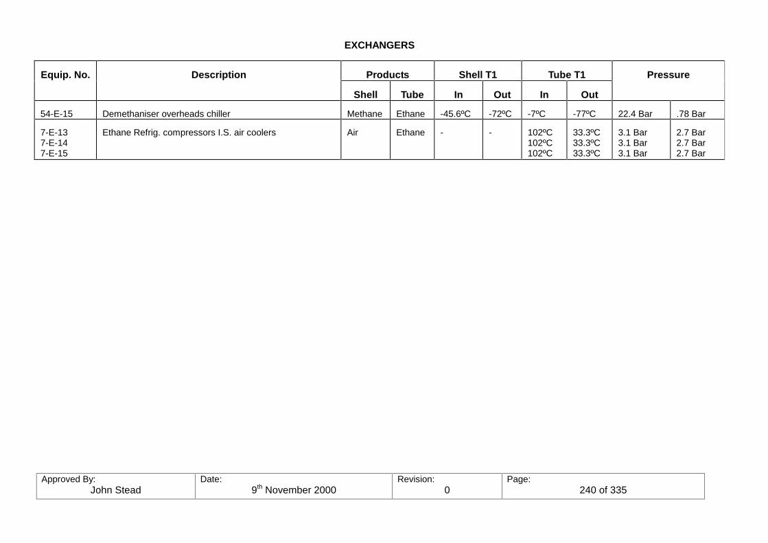
Approved By:John Stead
Date:9th November 2000
Revision:0
Page:240 of 335
EXCHANGERS
Products Shell T1 Tube T1Equip. No. Description
Shell Tube In Out In Out
Pressure
54-E-15 Demethaniser overheads chiller Methane Ethane -45.6ºC -72ºC -7ºC -77ºC 22.4 Bar .78 Bar
7-E-137-E-147-E-15
Ethane Refrig. compressors I.S. air coolers Air Ethane - - 102ºC102ºC102ºC
33.3ºC33.3ºC33.3ºC
3.1 Bar3.1 Bar3.1 Bar
2.7 Bar2.7 Bar2.7 Bar
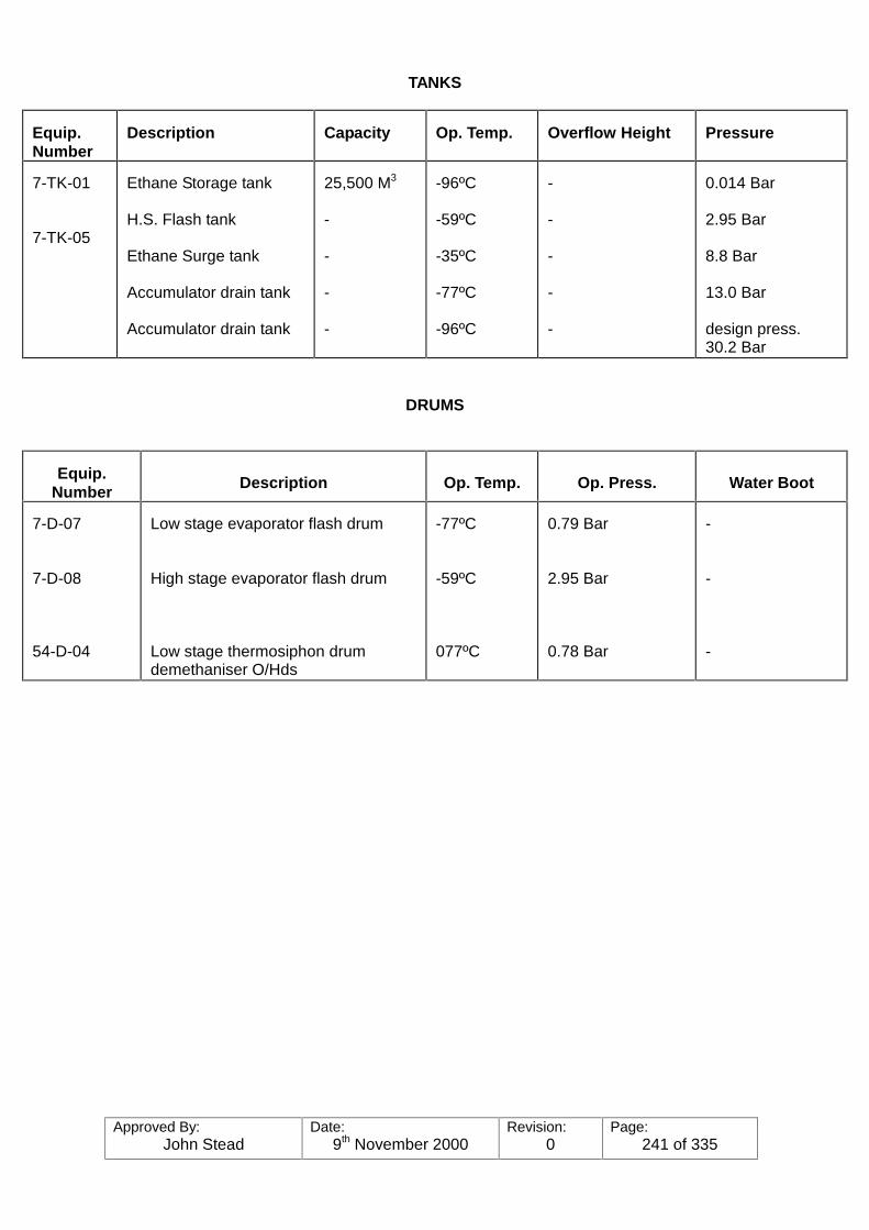
Approved By:John Stead
Date:9th November 2000
Revision:0
Page:241 of 335
TANKS
Equip.Number
Description Capacity Op. Temp. Overflow Height Pressure
7-TK-01
7-TK-05
Ethane Storage tank
H.S. Flash tank
Ethane Surge tank
Accumulator drain tank
Accumulator drain tank
25,500 M3
-
-
-
-
-96ºC
-59ºC
-35ºC
-77ºC
-96ºC
-
-
-
-
-
0.014 Bar
2.95 Bar
8.8 Bar
13.0 Bar
design press.30.2 Bar
DRUMS
Equip.Number Description Op. Temp. Op. Press. Water Boot
7-D-07
7-D-08
54-D-04
Low stage evaporator flash drum
High stage evaporator flash drum
Low stage thermosiphon drumdemethaniser O/Hds
-77ºC
-59ºC
077ºC
0.79 Bar
2.95 Bar
0.78 Bar
-
-
-

Approved By:John Stead
Date:9th November 2000
Revision:0
Page:242 of 335
INSTRUMENTSETHANE REFRIG.
INST. NO. DESCRIPTION SIGNAL LOCATION AIRFAILURE
RESETS
PIC-71001
PIC-71102
PIC-71003
PIC-71004
PIC-71005
PIC-71006
PIC-71007A
PIC-71007B
PIC-71043
PIC-71050
PIC-71055
PIC-71057
PIC-71062
PIC-71189
PIC-71190
PIC-71192
Pressure control on7-TK-05
Pressure control on7-TK-07
Surge Tank7-TK-06
Pressure Control
Pressure Controlsuction ethane tankblowers
Ethane product tostorage tank
Ethane storagepressure mtce.
Ethane storageoverpressure control
L.S. Suction7-C-04
H.S. Suction7-C-04
L.S. Suction7-C-05
H.S. Suction7-C-05
L.S. Suction7-C-06
H.S. Suction7-C-06
Speed control7-C-04
Speed control7-C-05
Speed control7-C-06
3-15 psi
3-15 psi
3-15 psi
3-15 psi
3-15 psi
3-15 psi
3-15 psi
3-15 psi
3-15 psi
3-15 psi
3-15 psi
3-15 psi
3-15 psi
3-15 psi
3-15 psi
3-15 psi
3-15 psi
NGL control room
NGL control room
NGL control room
NGL control room
NGL control room
NGL control room
NGL control room
NGL control room
NGL control room
NGL control room
NGL control room
NGL control room
NGL control room
NGL control room
NGL control room
NGL control room
NGL control room
AFO
AFO
AFO
AFO
AFO
AFO
AFO
AFO
AFO
AFO
AFO
AFO
AFO
AFO
AFO
AFO
AFO
-
-
-
FPV-71101 VIA LOSIG. SELECT RELAY-
-
-
-
-
-
-
-
-
-
-
-
-

Approved By:John Stead
Date:9th November 2000
Revision:0
Page:243 of 335
INSTRUMENTETHANE REFRIG.
INST. NO. DESCRIPTION SIGNAL LOCATION AIRFAILURE
RESETS
LIC-71108
LIC-71010
LIC-71012
LIC-51212
FIC-71001
FR-7102
FIC-71103
FIC-71006
FIC-71007
FR-71008
FIC-71009
FIC-71010
FR-71011
FIC-71012
FIC-71013
FR-71014
FIC-71015
Refrig. make-up to7-TK-05
Refrig. make-up to7-TK-07
Refrig. make-up to7-TK-08
Refrig. make-up to54-D-04
Tank 7-TK-01 recyclecontrol for blowers
Ethane to storage flow
Recycle flow controltank comp.
Recycle flow controltank comp.
Recycle flow controltank comp.
Steam flow to refrig.7-C-05
L.S. recycle flow7-C-04
H.S. recycle flow7-C-04
Steam flow to refrig.7-C-05
L.S. recycle flow7-C-05
H.S. recycle flow7-C-05
Steam flow to refrig.Turbine7-C-06
L.S. recycle flow7-C-06
7-C-05
Speed control7-C-06
3-15 psi
3-15 psi
3-15 psi
3-15 psi
3-15 psi
3-15 psi
3-15 psi
3-15 psi
3-15 psi
3-15 psi
3-15 psi
3-15 psi
3-15 psi
3-15 psi
3-15 psi
3-15 psi
3-15 psi
-
-
-
-
NGL control room
NGL control room
NGL control room
NGL control room
NGL control room
NGL control room
NGL control room
NGL control room
NGL control room
NGL control room
NGL control room
NGL control room
NGL control room
AFO
AFO
AFO
AFO
AFO
AFO
AFO
AFO
AFO
AFO
AFO
AFO
AFO
AFO
AFO
AFO
AFO
-
-
-
-
-
-
-
-
-
-
-
-
-
-
-
-
-
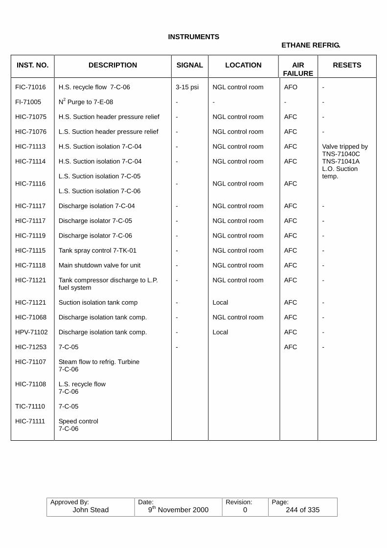
Approved By:John Stead
Date:9th November 2000
Revision:0
Page:244 of 335
INSTRUMENTSETHANE REFRIG.
INST. NO. DESCRIPTION SIGNAL LOCATION AIRFAILURE
RESETS
FIC-71016
FI-71005
HIC-71075
HIC-71076
HIC-71113
HIC-71114
HIC-71116
HIC-71117
HIC-71117
HIC-71119
HIC-71115
HIC-71118
HIC-71121
HIC-71121
HIC-71068
HPV-71102
HIC-71253
HIC-71107
HIC-71108
TIC-71110
HIC-71111
H.S. recycle flow 7-C-06
N2 Purge to 7-E-08
H.S. Suction header pressure relief
L.S. Suction header pressure relief
H.S. Suction isolation 7-C-04
H.S. Suction isolation 7-C-04
L.S. Suction isolation 7-C-05
L.S. Suction isolation 7-C-06
Discharge isolation 7-C-04
Discharge isolator 7-C-05
Discharge isolator 7-C-06
Tank spray control 7-TK-01
Main shutdown valve for unit
Tank compressor discharge to L.P.fuel system
Suction isolation tank comp
Discharge isolation tank comp.
Discharge isolation tank comp.
7-C-05
Steam flow to refrig. Turbine7-C-06
L.S. recycle flow7-C-06
7-C-05
Speed control7-C-06
3-15 psi
-
-
-
-
-
-
-
-
-
-
-
-
-
-
-
-
NGL control room
-
NGL control room
NGL control room
NGL control room
NGL control room
NGL control room
NGL control room
NGL control room
NGL control room
NGL control room
NGL control room
NGL control room
Local
NGL control room
Local
AFO
-
AFC
AFC
AFC
AFC
AFC
AFC
AFC
AFC
AFC
AFC
AFC
AFC
AFC
AFC
AFC
-
-
-
-
Valve tripped byTNS-71040CTNS-71041AL.O. Suctiontemp.
-
-
-
-
-
-
-
-
-
-
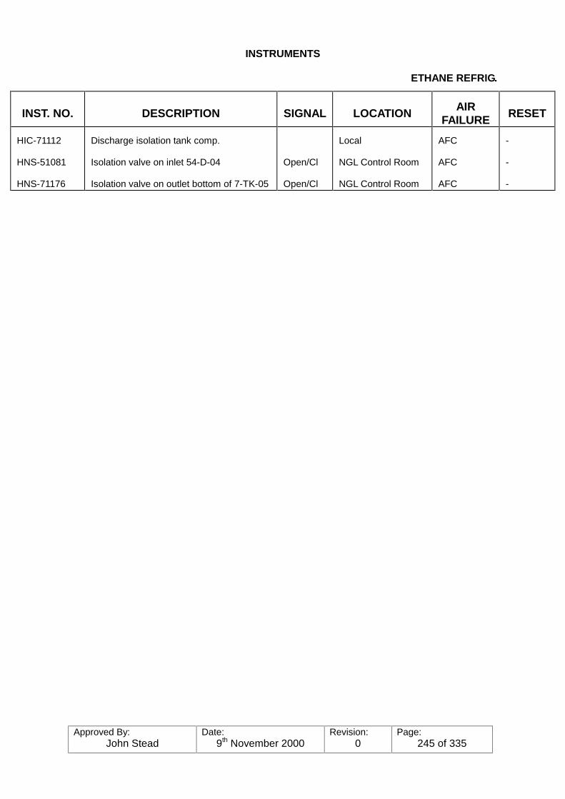
Approved By:John Stead
Date:9th November 2000
Revision:0
Page:245 of 335
INSTRUMENTS
ETHANE REFRIG.
INST. NO. DESCRIPTION SIGNAL LOCATION AIRFAILURE RESET
HIC-71112
HNS-51081
HNS-71176
Discharge isolation tank comp.
Isolation valve on inlet 54-D-04
Isolation valve on outlet bottom of 7-TK-05
Open/Cl
Open/Cl
Local
NGL Control Room
NGL Control Room
AFC
AFC
AFC
-
-
-
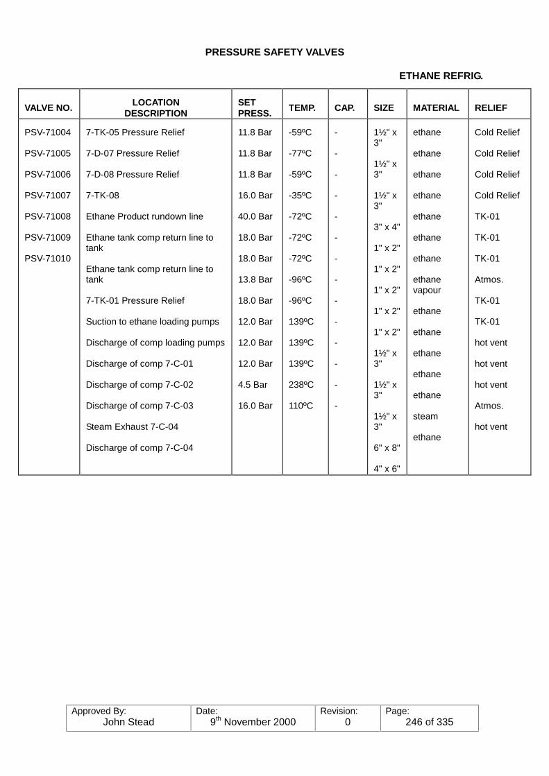
Approved By:John Stead
Date:9th November 2000
Revision:0
Page:246 of 335
PRESSURE SAFETY VALVES
ETHANE REFRIG.
VALVE NO. LOCATIONDESCRIPTION
SETPRESS.
TEMP. CAP. SIZE MATERIAL RELIEF
PSV-71004
PSV-71005
PSV-71006
PSV-71007
PSV-71008
PSV-71009
PSV-71010
7-TK-05 Pressure Relief
7-D-07 Pressure Relief
7-D-08 Pressure Relief
7-TK-08
Ethane Product rundown line
Ethane tank comp return line totank
Ethane tank comp return line totank
7-TK-01 Pressure Relief
Suction to ethane loading pumps
Discharge of comp loading pumps
Discharge of comp 7-C-01
Discharge of comp 7-C-02
Discharge of comp 7-C-03
Steam Exhaust 7-C-04
Discharge of comp 7-C-04
11.8 Bar
11.8 Bar
11.8 Bar
16.0 Bar
40.0 Bar
18.0 Bar
18.0 Bar
13.8 Bar
18.0 Bar
12.0 Bar
12.0 Bar
12.0 Bar
4.5 Bar
16.0 Bar
-59ºC
-77ºC
-59ºC
-35ºC
-72ºC
-72ºC
-72ºC
-96ºC
-96ºC
139ºC
139ºC
139ºC
238ºC
110ºC
-
-
-
-
-
-
-
-
-
-
-
-
-
-
1½" x3"
1½" x3"
1½" x3"
3" x 4"
1" x 2"
1" x 2"
1" x 2"
1" x 2"
1" x 2"
1½" x3"
1½" x3"
1½" x3"
6" x 8"
4" x 6"
ethane
ethane
ethane
ethane
ethane
ethane
ethane
ethanevapour
ethane
ethane
ethane
ethane
ethane
steam
ethane
Cold Relief
Cold Relief
Cold Relief
Cold Relief
TK-01
TK-01
TK-01
Atmos.
TK-01
TK-01
hot vent
hot vent
hot vent
Atmos.
hot vent

Approved By:John Stead
Date:9th November 2000
Revision:0
Page:247 of 335
PRESSURE SAFETY VALVES
ETHANE REFRIG.
VALVE NO. LOCATION/DESCRIPTION
SETPRESS.
TEMP. CAP. SIZE MATERIAL RELIEF
PSV-71004
PSV-71005
PSV-71006
PSV-71007
PSV-71008
PSV-71009
PSV-71010
PSV-71011
PSV-71012
PSV-71013
PSV-71014
PSV-71015
PSV-71016
PSV-71017
PSV-71018
7-TK-05 Pressure Relief
7-D-07 Pressure Relief
7-D-08 Pressure Relief
7-TK-08
Ethane Product rundown line
Ethane tank comp return line to tank
Ethane tank comp return line to tank7-TK-01
Pressure Relief
Suction to ethane loading pumps
Discharge of comp loading pumps
Discharge of comp 7-C-01
Discharge of comp 7-C-02
Discharge of comp 7-C-03
Steam Exhaust 7-C-04
Discharge of comp 7-C-04
11.8 Bar
11.8 Bar
11.8 Bar
16.0 Bar
40.0 Bar
18.0 Bar
18.0 Bar
13.8 Bar
18.0 Bar
12.0 Bar
12.0 Bar
12.0 Bar
4.5 Bar
16.0 Bar
-59ºC
-77ºC
-59ºC
-35ºC
-72ºC
-72ºC
-72ºC
-96ºC
-96ºC
139ºC
139ºC
139ºC
238ºC
110ºC
-
-
-
-
-
-
-
-
-
-
-
-
-
-
1½" x 3"
1½" x 3"
1½" x 3"
3" x 4"
1" x 2"
1" x 2"
1" x 2"
1" x 2"
1" x 2"
1½" x 3"
1½" x 3"
1½" x 3"
6" x 8"
4" x 6"
ethane
ethane
ethane
ethane
ethane
ethane
ethane
ethanevapour
ethane
ethane
ethane
ethane
ethane
steam
ethane
Cold Relief
Cold Relief
Cold Relief
Cold Relief
TK-01
TK-01
TK-01
Atmos.
TK-01
TK-01
hot vent
hot vent
hot vent
Atmos.
hot vent
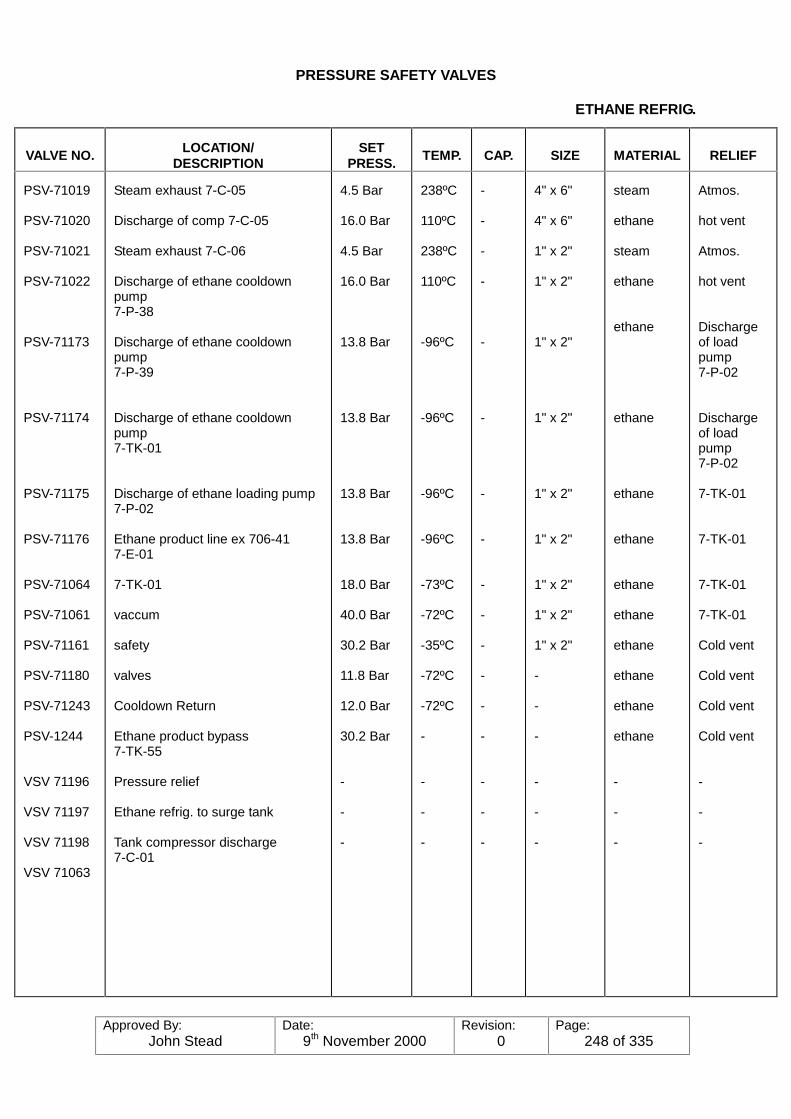
Approved By:John Stead
Date:9th November 2000
Revision:0
Page:248 of 335
PRESSURE SAFETY VALVES
ETHANE REFRIG.
VALVE NO. LOCATION/DESCRIPTION
SETPRESS.
TEMP. CAP. SIZE MATERIAL RELIEF
PSV-71019
PSV-71020
PSV-71021
PSV-71022
PSV-71173
PSV-71174
PSV-71175
PSV-71176
PSV-71064
PSV-71061
PSV-71161
PSV-71180
PSV-71243
PSV-1244
VSV 71196
VSV 71197
VSV 71198
VSV 71063
Steam exhaust 7-C-05
Discharge of comp 7-C-05
Steam exhaust 7-C-06
Discharge of ethane cooldownpump7-P-38
Discharge of ethane cooldownpump7-P-39
Discharge of ethane cooldownpump7-TK-01
Discharge of ethane loading pump7-P-02
Ethane product line ex 706-417-E-01
7-TK-01
vaccum
safety
valves
Cooldown Return
Ethane product bypass7-TK-55
Pressure relief
Ethane refrig. to surge tank
Tank compressor discharge7-C-01
4.5 Bar
16.0 Bar
4.5 Bar
16.0 Bar
13.8 Bar
13.8 Bar
13.8 Bar
13.8 Bar
18.0 Bar
40.0 Bar
30.2 Bar
11.8 Bar
12.0 Bar
30.2 Bar
-
-
-
238ºC
110ºC
238ºC
110ºC
-96ºC
-96ºC
-96ºC
-96ºC
-73ºC
-72ºC
-35ºC
-72ºC
-72ºC
-
-
-
-
-
-
-
-
-
-
-
-
-
-
-
-
-
-
-
-
-
4" x 6"
4" x 6"
1" x 2"
1" x 2"
1" x 2"
1" x 2"
1" x 2"
1" x 2"
1" x 2"
1" x 2"
1" x 2"
-
-
-
-
-
-
steam
ethane
steam
ethane
ethane
ethane
ethane
ethane
ethane
ethane
ethane
ethane
ethane
ethane
-
-
-
Atmos.
hot vent
Atmos.
hot vent
Dischargeof loadpump7-P-02
Dischargeof loadpump7-P-02
7-TK-01
7-TK-01
7-TK-01
7-TK-01
Cold vent
Cold vent
Cold vent
Cold vent
-
-
-
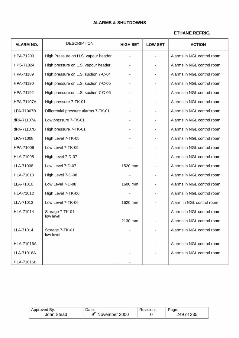
Approved By:John Stead
Date:9th November 2000
Revision:0
Page:249 of 335
ALARMS & SHUTDOWNS
ETHANE REFRIG.
ALARM NO. DESCRIPTION HIGH SET LOW SET ACTION
HPA-71203
HPS-71024
HPA-71189
HPA-71190
HPA-71192
HPA-71107A
LPA-71007B
dPA-71107A
dPA-71107B
LPA-71008
HPA-71009
HLA-71008
LLA-71008
HLA-71010
LLA-71010
HLA-71012
LLA-71012
HLA-71014
LLA-71014
HLA-71016A
LLA-71016A
HLA-71016B
High Pressure on H.S. vapour header
High pressure on L.S. vapour header
High pressure on L.S. suction 7-C-04
High pressure on L.S. suction 7-C-05
High pressure on L.S. suction 7-C-06
High pressure 7-TK-01
Differential pressure alarms 7-TK-01
Low pressure 7-TK-01
High pressure 7-TK-01
High Level 7-TK-05
Low Level 7-TK-05
High Level 7-D-07
Low Level 7-D-07
High Level 7-D-08
Low Level 7-D-08
High Level 7-TK-06
Low Level 7-TK-06
Storage 7-TK-01low level
Storage 7-TK-01low level
-
-
-
-
-
-
-
-
-
-
-
-
1520 mm
-
1600 mm
-
1620 mm
-
2130 mm
-
-
-
-
-
-
-
-
-
-
-
-
-
-
-
-
-
-
-
-
-
-
-
-
-
-
Alarms in NGL control room
Alarms in NGL control room
Alarms in NGL control room
Alarms in NGL control room
Alarms in NGL control room
Alarms in NGL control room
Alarms in NGL control room
Alarms in NGL control room
Alarms in NGL control room
Alarms in NGL control room
Alarms in NGL control room
Alarms in NGL control room
Alarms in NGL control room
Alarms in NGL control room
Alarms in NGL control room
Alarms in NGL control room
Alarm in NGL control room
Alarms in NGL control room
Alarms in NGL control room
Alarms in NGL control room
Alarms in NGL control room
Alarms in NGL control room

Approved By:John Stead
Date:9th November 2000
Revision:0
Page:250 of 335
ALARMS & SHUTDOWNS
ETHANE REFRIG.
ALARM NO. DESCRIPTION HIGH SET LOW SET ACTION
LLA-71016B
HLA-51213
LLA-51214
HTA-71003
HTA-71004
HTA-71005
HTA-71006
HTA-71007
HTA-71008
HTA-71009
HTA-71010
HTA-71011
HTA-71012
HTA-71013
HTA-71014
LTA-71040A,B,C.
LTA-71041A,B,C.
LTA-71001/41
Storage TK-01 low level
High level 54-D-04
Low level 54-D-04
High temp. L.S. discharge tank comp.7-C-01
High temp. H.S. discharge tank comp.7-C-01
High temp. L.S. discharge7-C-02
High temp. H.S. discharge7-C-02
High temp. L.S. discharge7-C-03
High temp. H.S. discharge7-C-04
L.S. discharge refrig. comp.7-C-04
H.S. discharge 7-C-04L.S. discharge 7-C-05
H.S. discharge 7-C-05L.S. discharge 7-C-06
H.S. discharge 7-C-06
Low temp. H.S. Suction of 7-C-04/05/06
Low temp. L.S. Suction of 7-C-04/05/06
Low temp. H.S. Suction of 7-C-04
-
1500mm
900mm
-
-
-
-
-
-
-
-
-
-
-
-
-
-
-
-
-
-
-
-
-
-
-
-
-
-
-
-
-
-
-
-
-
Alarms in NGL control room
Alarms in NGL control room
Alarms in NGL control room
Comp. shutdown Alarms inNGL control room
Comp. shutdown Alarms inNGL control room
Comp. shutdown Alarms inNGL control room
Comp. shutdown Alarms inNGL control room
Comp. shutdown Alarms inNGL control room
Comp. shutdown Alarms inNGL control room
Comp. shutdown Alarms inNGL control room
Comp. shutdown Alarms inNGL control room
Comp. shutdown Alarms inNGL control room
Comp. shutdown Alarms inNGL control room
Alarms in NGL control room
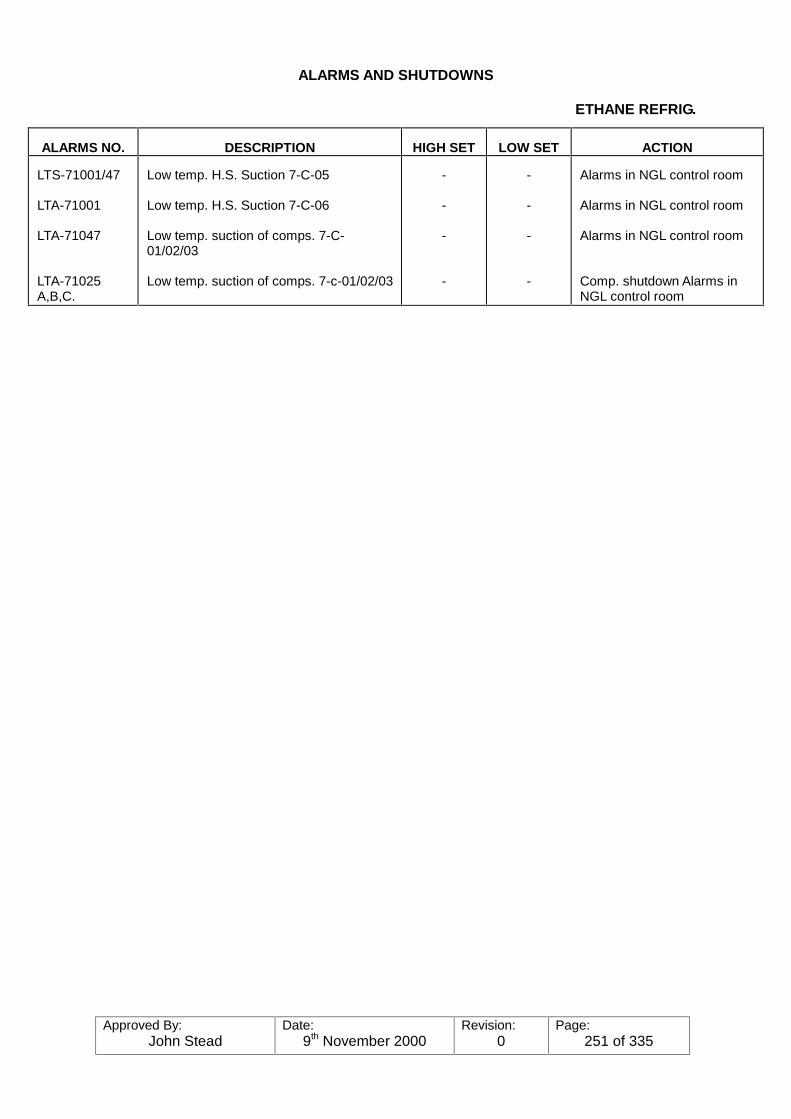
Approved By:John Stead
Date:9th November 2000
Revision:0
Page:251 of 335
ALARMS AND SHUTDOWNS
ETHANE REFRIG.
ALARMS NO. DESCRIPTION HIGH SET LOW SET ACTION
LTS-71001/47
LTA-71001
LTA-71047
LTA-71025A,B,C.
Low temp. H.S. Suction 7-C-05
Low temp. H.S. Suction 7-C-06
Low temp. suction of comps. 7-C-01/02/03
Low temp. suction of comps. 7-c-01/02/03
-
-
-
-
-
-
-
-
Alarms in NGL control room
Alarms in NGL control room
Alarms in NGL control room
Comp. shutdown Alarms inNGL control room
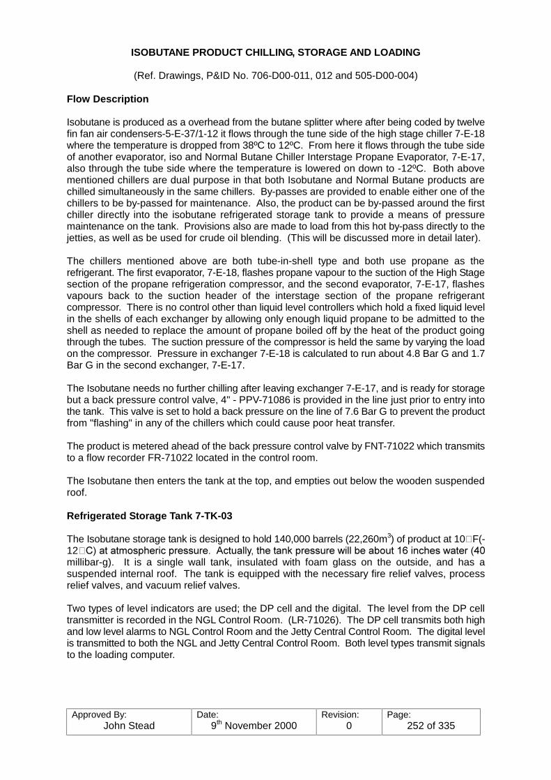
Approved By:John Stead
Date:9th November 2000
Revision:0
Page:252 of 335
ISOBUTANE PRODUCT CHILLING, STORAGE AND LOADING
(Ref. Drawings, P&ID No. 706-D00-011, 012 and 505-D00-004)
Flow Description
Isobutane is produced as a overhead from the butane splitter where after being coded by twelvefin fan air condensers-5-E-37/1-12 it flows through the tune side of the high stage chiller 7-E-18where the temperature is dropped from 38ºC to 12ºC. From here it flows through the tube sideof another evaporator, iso and Normal Butane Chiller Interstage Propane Evaporator, 7-E-17,also through the tube side where the temperature is lowered on down to -12ºC. Both abovementioned chillers are dual purpose in that both Isobutane and Normal Butane products arechilled simultaneously in the same chillers. By-passes are provided to enable either one of thechillers to be by-passed for maintenance. Also, the product can be by-passed around the firstchiller directly into the isobutane refrigerated storage tank to provide a means of pressuremaintenance on the tank. Provisions also are made to load from this hot by-pass directly to thejetties, as well as be used for crude oil blending. (This will be discussed more in detail later).
The chillers mentioned above are both tube-in-shell type and both use propane as therefrigerant. The first evaporator, 7-E-18, flashes propane vapour to the suction of the High Stagesection of the propane refrigeration compressor, and the second evaporator, 7-E-17, flashesvapours back to the suction header of the interstage section of the propane refrigerantcompressor. There is no control other than liquid level controllers which hold a fixed liquid levelin the shells of each exchanger by allowing only enough liquid propane to be admitted to theshell as needed to replace the amount of propane boiled off by the heat of the product goingthrough the tubes. The suction pressure of the compressor is held the same by varying the loadon the compressor. Pressure in exchanger 7-E-18 is calculated to run about 4.8 Bar G and 1.7Bar G in the second exchanger, 7-E-17.
The Isobutane needs no further chilling after leaving exchanger 7-E-17, and is ready for storagebut a back pressure control valve, 4" - PPV-71086 is provided in the line just prior to entry intothe tank. This valve is set to hold a back pressure on the line of 7.6 Bar G to prevent the productfrom "flashing" in any of the chillers which could cause poor heat transfer.
The product is metered ahead of the back pressure control valve by FNT-71022 which transmitsto a flow recorder FR-71022 located in the control room.
The Isobutane then enters the tank at the top, and empties out below the wooden suspendedroof.
Refrigerated Storage Tank 7-TK-03
The Isobutane storage tank is designed to hold 140,000 barrels (22,260m3) of product at 10�F(-12�&��DW�DWPRVSKHULF�SUHVVXUH���$FWXDOO\��WKH�WDQN�SUHVVXUH�ZLOO�EH�DERXW����LQFKHV�ZDWHU����millibar-g). It is a single wall tank, insulated with foam glass on the outside, and has asuspended internal roof. The tank is equipped with the necessary fire relief valves, processrelief valves, and vacuum relief valves.
Two types of level indicators are used; the DP cell and the digital. The level from the DP celltransmitter is recorded in the NGL Control Room. (LR-71026). The DP cell transmits both highand low level alarms to NGL Control Room and the Jetty Central Control Room. The digital levelis transmitted to both the NGL and Jetty Central Control Room. Both level types transmit signalsto the loading computer.
Approved By:John Stead
Date:9th November 2000
Revision:0
Page:253 of 335
A single pressure control loop is used to control tank operation. The loop is taken off as a signalfrom one of two parallel tank pressure transmitter, (dPNT-71093A and B). One of thetransmitters is a spare. A malfunctioning transmitter will send an alarm, (dPA-71093A), to theNGL Control Room and when this happens, the spare transmitter is placed in service. Two setsof high and low tank pressure alarms are included on the NGL panel board. One set operatesdirectly off the tank pressure and the other set operates off the pressure transmitter in thepressure control loop. The tank pressure is continuously recorded in both the NGL and the JettyCentral Control Room.
Isobutane Tank Pressure Maintenance (7-TK-03)
Unlike the ethane and propane refrigerated tanks which use tank vapour compressors to controltank pressures, the isobutane storage tank uses an external liquid circulation system., As tankpressure tends to increase above the set pressure, the circulated liquid is chilled by diverting itthrough the isobutane chiller low stage propane evaporate 7-E-16, and as the tank pressuretends to fall below the set point the liquid is heated, by diverting the circulation from the chillerto the Glycol heater 7-E-24.
As the tank pressure increases, pressure controller PIC-71093C located on the tank, will openPPV-71093C1 which established the circulated Isobutane through the chiller. If this is notenough cooling to bring the tank pressure back down, then another pressure controller, PIC-71093B, will open the 18" valve PPV-71093B to the refrigerated flare system. If the pressurecontinues to increase, then pressure switch PNS-71093 will block in the Isobutane product makestream to the tank. This will result in having to go to either the flare, fuel system, or stabilisedcrude oil blending with the isobutane product until the pressure is alleviated.
On decreasing tank pressure the circulation of Isobutane will be directed through the heatingcircuit by diverting it to the heater and back to the tank. This is done automatically by the samecontroller which controls the chilling circuit. If this does not satisfy the tank pressure, then a lowpressure controller, PIC-71093A will open PPV-71093A allowing the isobutane product to by-pass all the chillers, and go directly into the tank hot. If this still is not sufficient to stop the fallingtank pressure a pressure switch, PNS-71093B, will shut down the loading pumps to the Jetty. This is most likely to happen only when loading two ships simultaneously, Isobutane productionrate low and the circulating heating system malfunctions.
Two circulating pumps are provided, 7-P-07/08 one for service, the other for a stand-by. A pumpruns continually with a flow controller, FIC-71049 maintaining a constant flow back to the tank. A part of the flow is diverted to either the chiller or the heater but not both at the same time. Allof the flow is diverted back to the tank if neither chilling, nor heating is required. Pumpcirculation is 165m3/hr at about 7 Bar G pressure. The pump discharge headers and piping backto the tank is 6 inch pipe, but a 4" line takes off the header for the heating or cooling circulation. A 4" return from either the heater, or cooler is utilised to recycle back to the top of the tank.
At maximum tank pressure change, up to 40% of the circulation flow is routed to either the chilleror heater by the split range controller. The control will be between 3 and 9 PSI on decreasingtank pressure, and between 9 and 15 PSI on increasing tank pressure.
The chilled, or hot Isobutane is routed to the top of the tank where it is sprayed as a fire mistthrough four equally spaced spray nozzles.
The cold product will tend to condense the tank vapours to low the pressure, likewise the hotisobutane mist will evaporate quickly to raise the tank pressure as required. Filters are providedin the line ahead of the spray nozzles and may have to be cleaned from time to time.
Approved By:John Stead
Date:9th November 2000
Revision:0
Page:254 of 335
The heaters use hot glycol for heating source, and is designed to also take care of the vapourdemands when loading two refrigerated ships at the same time, providing the Isobutaneproduction rate is up to normal. The temperature of the heated Isobutane is controlled byvarying the amount of glycol circulated through the heater with TIC-71039, which controls a 3-way control valve TPV-71039 in the glycol line. This valve functions by by-passing part of thehot glycol around the heater.
Circulation Pumps
Two David Brown Bingham electric driven centrifugal circulation pumps are provided on forservice and the other as stand-by. They are driven by 100 hp motors. Having a rated capacityof 182m3/hr. The pumps operate at 1460 RPM. Bearings are lubricated by pumpage - productmechanical scales are provided.
Approved By:John Stead
Date:9th November 2000
Revision:0
Page:255 of 335
UNIT DATA
TYPE OF SERVICE Iso-butane tank/circulating tank LIQUID ISO C4 @ -12ºC P.T.
CAPACITY 182M3/hr GPM HEAD

Approved By:John Stead
Date:9th November 2000
Revision:0
Page:256 of 335
Hot Isobutane Loading
In addition to refrigerated Isobutane loading facilities have been made to load hot Isobutaneproduct at Jetties 3, 6, 7 or 8. This system is designed to load one maximum size ship at anyone time. It will load a 2880 cu. meter ship in 10 hours or less.
Two Goulds. Mode VIC 3 stage vertical "can" type pumps, 7-P-31/32 are provided for loadinght isobutane directly to the ships. They are driven with 200 hp electric motors at 1450 RPM, andare designed for a minimum flow of 91m3/hr at 13 bar G. Maximum flow is 310m3/hr.
The pumps take suction off a 14 inch line coming off the bottom of the tank through 8" suctionlaterals. The pumps discharge through 8" laterals into the main 8" discharge line going to theisobutane loading heater, 7-E-23, where by using hot glycol, the isobutane is heated to around20ºC. The heated Isobutane then is routed to the Jetties through the 8" loading line, 8" 551L90-080.
Temperature of the Isobutane is controlled by TIC-71079 which operates TPV-71079 in the hotglycol line. This is a three way valve, which by-passes the desired amount of hot glycol aroundthe heater to attain the desired loading temperature., These controls are located in the JettyControl Room.
Hot Isobutane can be routed directly to the Jetties off the main make stream before it has beenchilled if necessary.
Refrigerated Isobutane Loading
Cool Down
Refrigerated Isobutane can be loaded at either Jetty No. 3 or 4, or may be loaded simultaneouslyto both jetties. The entire loading system is kept in a cold state by circulating a small amount ofIsobutane from the tank through the loading system to the jetties and then returning through aseparate line back to the tank.
Two loading cool down pumps 7-P-42/43 are provided, one of which is a spare they arecentrifugal David Brown Bingham pumps using 215 HP 2960 RPM motors for power. Ratedcapacity is 23m3/hr. Outboard end bearings are lubricated by pumpage. Drive end is in themotor.
The cooldown system can be automatically controlled and sequentially routed through themetering stations and meter provers by the Hetty Control Room computer. The cooldown pumpsshould be shut down during loading operations, and the cooldown return control valve shut inat the Jetty being used for loading. The Jetty not being used for loading can remain open forcooldown but the cooldown flow will then be taken out of the refrigerated loading pumps.
Loading
Four refrigerated Isobutane loading pumps, 7-P-12/13/14 and 48 have been provided to allowfor simultaneous loading to Jetties 3 and 4, as stated above. Each Jetty system had beendesigned to load a maximum size ship of 15,000 cubic metres in 12 hors. There is sufficientstorage capacity to load 15,000 cubic meter ships at the same time.
Approved By:John Stead
Date:9th November 2000
Revision:0
Page:257 of 335
Each pump is designed for 470m3/hr at 6.6 bar g discharge pressure. Three pumps should beused when loading the maximum 15,000 meter ship. The pumps are controlled from the JettyControl Room. Low tank pressure will automatically shut down the loading pumps, or they canbe shut down remotely either by the operator, or during an ESD situation. The main valve in thesuction header, 24" - 751L90-040, is remotely operated, as well as the individual pump dischargevalves, but the individual pump suction valves must be hand operated at the pumps site.
The pumps take suction out of the 20" common header, and discharge through 8 inch dischargelaterals into a common 20" loading line to he jetty area. A flow meter, FI-71045, is used tocontrol minimum and/or excess flow back to the storage tank through HPV-71042 in the 4"recycle line, 4" 751L90-057 back to the top of the tank.
Provisions for relieving hydrostatic pressure build up in all pumps here is made by installing a2" by-pass with a drilled orifice plate in it between the discharge block valves and pumps to the4" cooldown return line from the Jetties. The pump "cans" are also vented in the same manner. These valves should remain open at all times.
The permissive logic lever switch at the Jetty must be activated before loading can be started.

Approved By:John Stead
Date:9th November 2000
Revision:0
Page:258 of 335
PRE-STARTING INSTRUCTIONS
1. Clean-up the unit and check the auxiliary piping to see that it is installed properly. Ifpossible, install a suction strainer.
2. Check the piping. Make a thorough inspection of all piping including strainers, if installed. Also check auxiliary piping such as seal liquid and cooling water piping.
3. Check the alignment. See alignment and coupling instructions.
4. Check the driver rotation before coupling to the pump to make certain that it will rotatein the same direction as indicated by the arrow on the pump.
5. Mechanical seal - refer to seal drawing and G.A. drawing.
STARTING THE PUMP
Use the following procedure:
1. PRIMING
Before starting a centrifugal pump, the casing and suction piping must be completelyfilled with liquid. The rotating parts within the pump depend upon this liquid forlubrication and nay seize if the pump is operated dry.
2. If used, turn on cooling water services and sealing liquid to the stuffing box.
3. Close the discharge valve, if it is not already closed, and check that the suction valve isfully open. Sometimes it is helpful to slightly crack the discharge valve to help providefor the removal of vapours at start-up.
4. Start the driver. As soon as the pump is up to rated speed, open the discharge valveslowly to avoid abrupt changes in velocity and surging in the suction line. DO NOTOPERATE THE PUMP AGAINST A CLOSED DISCHARGE VALVE FOR ANY LENGTHOF TIME, as the liquid in the pump will be heated until it vapourises. This will cause yourpump to seize by running dry.
5. Check for vibration. Vibration indicates improper alignment, and the unit should be shutdown and realigned.
6. Check for any increase in pressure drop across the suction screen, if used. The screenshould be cleaned if such a drop occurs. Leave the screen in the line for 24 hoursbefore removing.
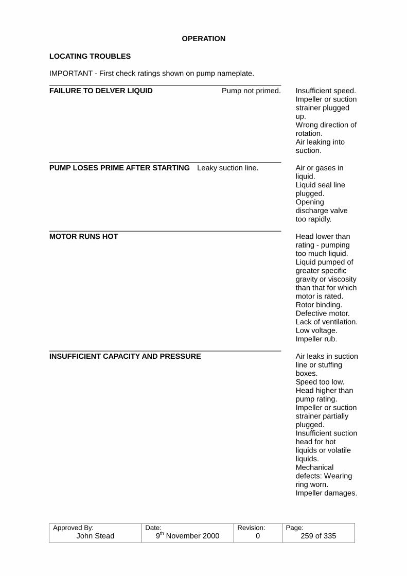
Approved By:John Stead
Date:9th November 2000
Revision:0
Page:259 of 335
OPERATION
LOCATING TROUBLES
IMPORTANT - First check ratings shown on pump nameplate. FAILURE TO DELVER LIQUID Pump not primed. Insufficient speed.
Impeller or suctionstrainer pluggedup.Wrong direction ofrotation.Air leaking intosuction.
PUMP LOSES PRIME AFTER STARTING Leaky suction line. Air or gases in
liquid.Liquid seal lineplugged.Openingdischarge valvetoo rapidly.
MOTOR RUNS HOT Head lower than
rating - pumpingtoo much liquid.Liquid pumped ofgreater specificgravity or viscositythan that for whichmotor is rated.Rotor binding.Defective motor.Lack of ventilation.Low voltage.Impeller rub.
INSUFFICIENT CAPACITY AND PRESSURE Air leaks in suction
line or stuffingboxes.Speed too low.Head higher thanpump rating.Impeller or suctionstrainer partiallyplugged.Insufficient suctionhead for hotliquids or volatileliquids.Mechanicaldefects: Wearingring worn.Impeller damages.

Approved By:John Stead
Date:9th November 2000
Revision:0
Page:260 of 335
PUMP VIBRATES, OR IS NOISY Misalignment.
Foundation notsufficiently rigid.Impeller partiallyplugged, causingunbalance.Mechanicaldefects in pump ordriver:Shaft bentRotating elementbinds.Suction ordischarge pipe notanchored.Vapour-bind(pump noisy).
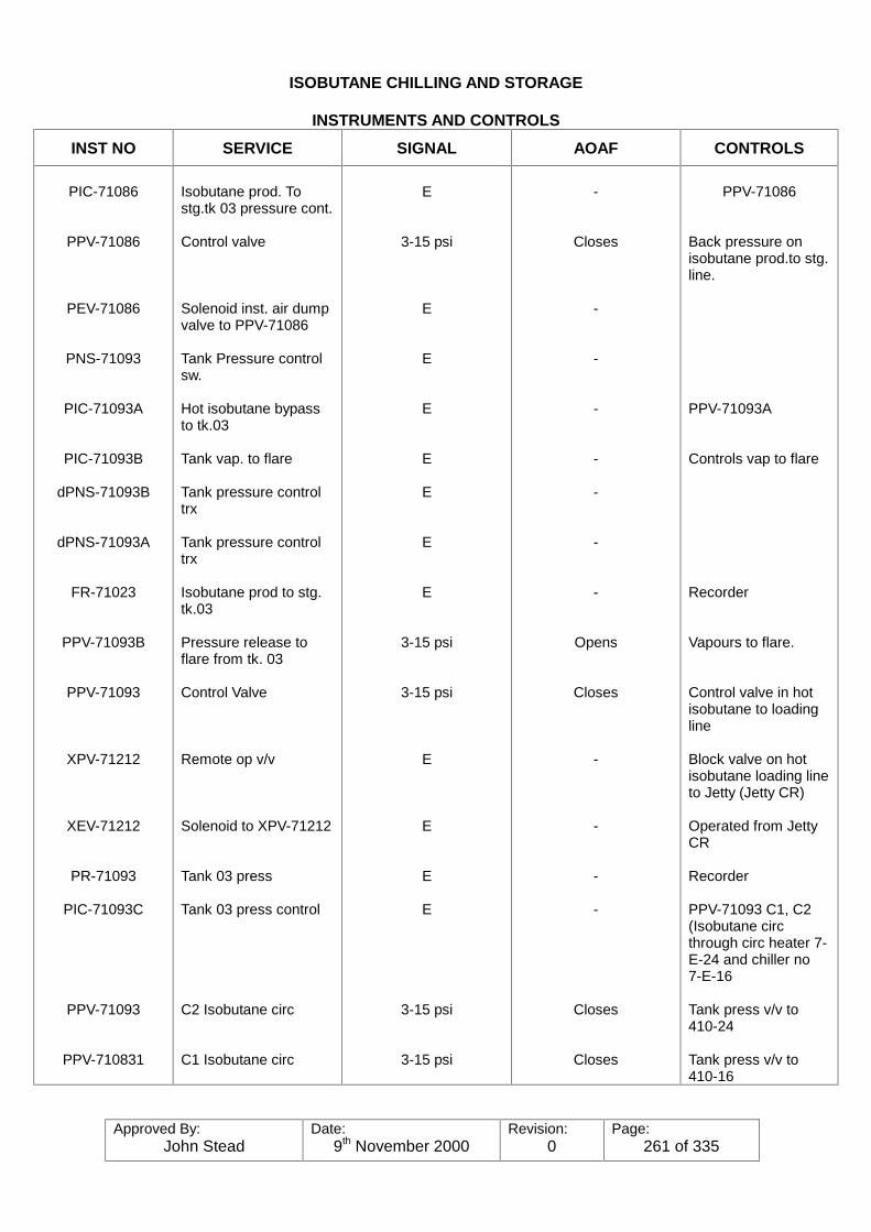
Approved By:John Stead
Date:9th November 2000
Revision:0
Page:261 of 335
ISOBUTANE CHILLING AND STORAGE
INSTRUMENTS AND CONTROLS
INST NO SERVICE SIGNAL AOAF CONTROLS
PIC-71086
PPV-71086
PEV-71086
PNS-71093
PIC-71093A
PIC-71093B
dPNS-71093B
dPNS-71093A
FR-71023
PPV-71093B
PPV-71093
XPV-71212
XEV-71212
PR-71093
PIC-71093C
PPV-71093
PPV-710831
Isobutane prod. Tostg.tk 03 pressure cont.
Control valve
Solenoid inst. air dumpvalve to PPV-71086
Tank Pressure controlsw.
Hot isobutane bypassto tk.03
Tank vap. to flare
Tank pressure controltrx
Tank pressure controltrx
Isobutane prod to stg.tk.03
Pressure release toflare from tk. 03
Control Valve
Remote op v/v
Solenoid to XPV-71212
Tank 03 press
Tank 03 press control
C2 Isobutane circ
C1 Isobutane circ
E
3-15 psi
E
E
E
E
E
E
E
3-15 psi
3-15 psi
E
E
E
E
3-15 psi
3-15 psi
-
Closes
-
-
-
-
-
-
-
Opens
Closes
-
-
-
-
Closes
Closes
PPV-71086
Back pressure onisobutane prod.to stg.line.
PPV-71093A
Controls vap to flare
Recorder
Vapours to flare.
Control valve in hotisobutane to loadingline
Block valve on hotisobutane loading lineto Jetty (Jetty CR)
Operated from JettyCR
Recorder
PPV-71093 C1, C2(Isobutane circthrough circ heater 7-E-24 and chiller no7-E-16
Tank press v/v to410-24
Tank press v/v to410-16
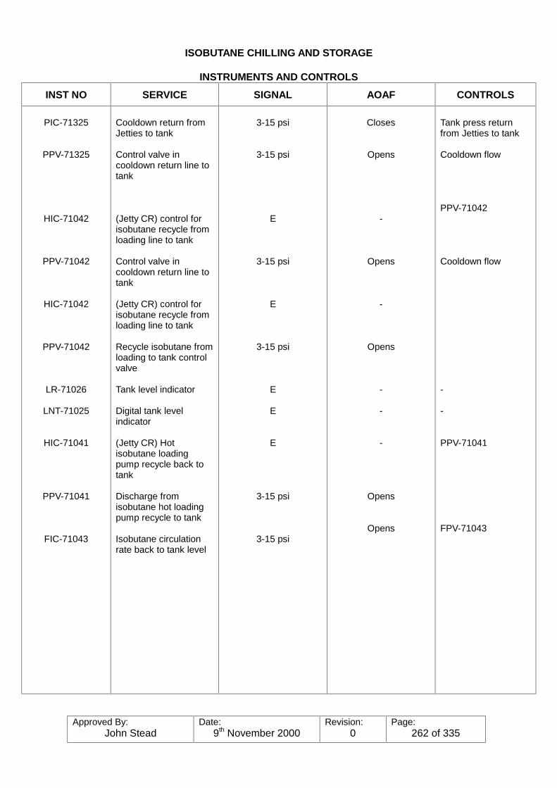
Approved By:John Stead
Date:9th November 2000
Revision:0
Page:262 of 335
ISOBUTANE CHILLING AND STORAGE
INSTRUMENTS AND CONTROLS
INST NO SERVICE SIGNAL AOAF CONTROLS
PIC-71325
PPV-71325
HIC-71042
PPV-71042
HIC-71042
PPV-71042
LR-71026
LNT-71025
HIC-71041
PPV-71041
FIC-71043
Cooldown return fromJetties to tank
Control valve incooldown return line totank
(Jetty CR) control forisobutane recycle fromloading line to tank
Control valve incooldown return line totank
(Jetty CR) control forisobutane recycle fromloading line to tank
Recycle isobutane fromloading to tank controlvalve
Tank level indicator
Digital tank levelindicator
(Jetty CR) Hotisobutane loadingpump recycle back totank
Discharge fromisobutane hot loadingpump recycle to tank
Isobutane circulationrate back to tank level
3-15 psi
3-15 psi
E
3-15 psi
E
3-15 psi
E
E
E
3-15 psi
3-15 psi
Closes
Opens
-
Opens
-
Opens
-
-
-
Opens
Opens
Tank press returnfrom Jetties to tank
Cooldown flow
PPV-71042
Cooldown flow
-
-
PPV-71041
FPV-71043
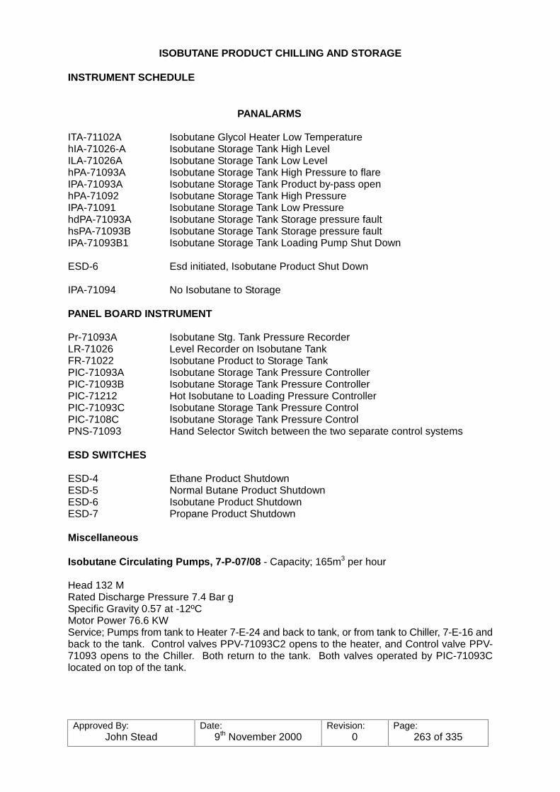
Approved By:John Stead
Date:9th November 2000
Revision:0
Page:263 of 335
ISOBUTANE PRODUCT CHILLING AND STORAGE
INSTRUMENT SCHEDULE
PANALARMS
ITA-71102A Isobutane Glycol Heater Low TemperaturehIA-71026-A Isobutane Storage Tank High LevelILA-71026A Isobutane Storage Tank Low LevelhPA-71093A Isobutane Storage Tank High Pressure to flareIPA-71093A Isobutane Storage Tank Product by-pass openhPA-71092 Isobutane Storage Tank High PressureIPA-71091 Isobutane Storage Tank Low PressurehdPA-71093A Isobutane Storage Tank Storage pressure faulthsPA-71093B Isobutane Storage Tank Storage pressure faultIPA-71093B1 Isobutane Storage Tank Loading Pump Shut Down
ESD-6 Esd initiated, Isobutane Product Shut Down
IPA-71094 No Isobutane to Storage
PANEL BOARD INSTRUMENT
Pr-71093A Isobutane Stg. Tank Pressure RecorderLR-71026 Level Recorder on Isobutane TankFR-71022 Isobutane Product to Storage TankPIC-71093A Isobutane Storage Tank Pressure ControllerPIC-71093B Isobutane Storage Tank Pressure ControllerPIC-71212 Hot Isobutane to Loading Pressure ControllerPIC-71093C Isobutane Storage Tank Pressure ControlPIC-7108C Isobutane Storage Tank Pressure ControlPNS-71093 Hand Selector Switch between the two separate control systems
ESD SWITCHES
ESD-4 Ethane Product ShutdownESD-5 Normal Butane Product ShutdownESD-6 Isobutane Product ShutdownESD-7 Propane Product Shutdown
Miscellaneous
Isobutane Circulating Pumps, 7-P-07/08 - Capacity; 165m3 per hour
Head 132 MRated Discharge Pressure 7.4 Bar gSpecific Gravity 0.57 at -12ºCMotor Power 76.6 KWService; Pumps from tank to Heater 7-E-24 and back to tank, or from tank to Chiller, 7-E-16 andback to the tank. Control valves PPV-71093C2 opens to the heater, and Control valve PPV-71093 opens to the Chiller. Both return to the tank. Both valves operated by PIC-71093Clocated on top of the tank.
Approved By:John Stead
Date:9th November 2000
Revision:0
Page:264 of 335
IC4 LOADING PUMPS, 7-P-12/13/14 and 48 Capacity; 1725 Imp. Aal/min.
4 stage centrifugal, Deep well or can typeMotor Power, 210 HP motor24" Suction piping from tank, 8" discharge laterals20" Loading LinePower operated discharge valves, HPV-71156,57,58 and 59Manually operated Suction valves
Approved By:John Stead
Date:9th November 2000
Revision:0
Page:265 of 335
NORMAL BUTANE PRODUCT CHILLING, STORAGE AND LOADING(Ref. drawings:P&ID 7809-505-D00-007; 706-D00-011.-12)
A. NORMAL BUTANE PRODUCT CHILLING AND STORAGE
1. Introduction
The normal butane is produced as a kettle product (5th tray) from the butane splittertower, 706-950-04, in the NGL area. Normal production to refrigerated storage shouldbe approximately 1991 m3/Day at 38ºC and 7.9 Bar G pressure. The Butane leaves thecolumn and is pumped through an air fin cooler and then routed through a series ofchillers, where the temperature is reduced to -1ºC before being admitted at the top of thetank. Refrigerated normal butane can be loaded to tankers at either Jetty No. 3 or 4, orsimultaneously to both. Hot normal butane may be loaded to Jetties 3,6,7 and 8. It canalso be routed to crude oil blending (P&ID No. 78098-706-D00-014). Hot normal butanemay also be loaded directly off the make line by-passing the chilling and storage areascompletely. Refrigerated normal butane may be heated and loaded to tankers as a hotproduct also.
2. Flow and Equipment Description
Normal butane is pumped with pumps no. 706-670-27 or 28 through a 6" discharge linethrough an air fin cooler, 706-410-38, where the temperature is lowered from 72ºC toaround 38ºC. No control is supplied here other than stopping or starting fans.
The product then flows on to the chilling section where it is routed through the tube sideof an exchanger located on the inside of the iso and normal butane chiller high stagepropane evaporator, 706-410-18, which is a shell and tube type exchanger using highstage propane refrigerant boiling at 7ºC, 4.8 Bar G pressure.
Just prior to entering this exchanger, however a 6" line (6" 751L80-007) takes off theproduct line and is tied directly into the tank to be used for tank pressure maintenanceif necessary. Another line, 6" 751L80-160, takes off of the line 007 and goes directly tothe Jetties for normal butane blending. Also, a means to switch the butane to the flareis provided downstream of the air fin fan cooler.
The exchanger mentioned is a dual type exchanger, that is, it also serves the purposeof chilling the iso-butane make stream. The only control is the liquid level control whichmaintains a constant liquid level of propane over the two heat exchangers on the inside. The vapours from the evaporator are routed to the high stage suction of the propanerefrigeration compressor.
The normal butane product leaves this exchanger at 12 ºC and then is routed throughthe tube section of another exchanger located inside of the iso and normal butane chillerinter stage propane evaporator 706-410-17. Like the proceeding evaporator, this is dualservice as it also chills iso-butane. Propane boiling at-16ºC at 1.7 Bar G pressure to thesuction of the inter stage section of the propane refrigeration compressor supplies thecooling here. It also is equipped with a liquid level control to control the level of liquidpropane in the shell side of the evaporator.
This chiller normally operates at -16º to 17ºC, and since the storage temperature fornormal is -6�&��LW�LV�QRW�QHFHVVDU\�WR�SXW�DOO�WKH�QRUPDO�EXWDQH�WKURXJK�LW���$ERXW�KDOI�RIthe normal butane is routed through the chiller with an outlet temperature of -12ºC; theremaining half is by-passed around the chiller and blended back into the chilled effluentto come up with a resultant temperature of -1ºC. This split range flow is obtained byutilising a three-way temperature control valve, TPV-71015 controlled with TIC-71015.
Approved By:John Stead
Date:9th November 2000
Revision:0
Page:266 of 335
The control valve is located in the product stream upstream of the chiller, and thecontroller is on the NGL panel board. Temperature here should be set at about 5ºC to1ºC below the storage tank temperature. This amount of sub-cooling is to preventflashing when admitted to the tank.
The normal butane product now leaves this exchanger and is routed to the top of thetank where it is actually emptied out of the line just below the suspended wooden innerroof. A back pressure motor valve, PPV-71072, is located in the product stream on topof the tank where it is actually emptied out of the line just below the suspend down innerroof. A back pressure motor valve, PPV-71072, is located in the product stream on topof the tank, and is designed to hold a back pressure of about 6.2 Bar g on the butanesystem to prevent flashing across any of the exchangers or metering equipment. Thisis controlled by PIC-71072 located in the NGL Control Room. (This pressure may haveto be increased in the event of direct hot loading off the make line). The product flowrate is metered and recorded in the NGL Control Room with FR-71019.
Refrigerated normal butane can be loaded at either Jetty 3 or 4 or may be loadedsimultaneously at both. The entire loading system is kept at a temperature of-1ºC bycirculating a small volume of product from the bottom of the storage tank through theloading system to the jetties and returning through a separate line back to the storagetank (details later).
Loading hot butane to unrefrigerated tanks is also possible to Jetties 3,6,7 and 8. Thesystem is designed to load a maximum sized ship of 2,880 cubic metre capacity in 10hours. Hot loading is accomplished in two ways - 1) byre-heating refrigerated butaneand pumping to the ships, and 2) loading directly off the make-line.
3. REFRIGERATED STORAGE TANK, 706-950-04
A. Description
The normal butane storage tank is designed to hold 46,000 m3 of product at -1ºC andatmospheric pressure. It is a single wall tank, insulated on the outside with foam glassand has a suspended wooden internal roof. The tank dimensions are 44,500 mmdiameter x 30,758 mm in height. It is designed for a butane mixture with an averagetemperature of -4ºC at atmospheric pressure.
Two types of level indicators are used; the DP cell and the digital. The DP cell istransmitted into the NGL Control Room and is displayed in millimetres.
The following tank pressure relief valves are provided:
PSV-71233-10"-Relieve to atmospheric atPSV-71026-10"-Relieve to atmospheric atFSV-71227-10"-Relieve to atmospheric atFSV-71228-10"-Relieve to atmospheric atFSV-71229-10"-Relieve to atmospheric at
Vacuum relief valves:
VSV-71230-10"-Relieve atVSV-71231-10"-Relieve atVSV-71232-10"-Relieve at
In addition to the above, an 18" valve, PPV-71081B controlled from PIC-71081A, is setto relieve to the refrigerated cold ground flare at
Approved By:John Stead
Date:9th November 2000
Revision:0
Page:267 of 335
Hydrostatic relief is supplied for lines subject to occasional blocked in conditions.
Tank temperature near the bottom is transmitted into the Control Room - T1001/85.
A single pressure control loop is used to control the various tank operations. The loopis taken off as a signal from one of the two parallel tank pressure transmitter, dPNT-71081A and dPNT-71081B. One transmitter is a spare. A malfunction of a transmitterwill alarm in the NGL Control Room (hdPA-71081A and hdPA-71081B), at which time thespare transmitter is placed in service and actions taken to repair the malfunction. Twosets of high and low pressure alarms are provided. One set operates directly off thetank, hPA-71079, and the other off the tank pressure transmitted, hPA-71081A for highpressure and IPA-71078 and IPA-71081A for the low pressure alarm. The tank pressuretransmitted off the control loop is continuously recorded in the NGL and Jetty ControlRooms.
b. Tank Pressure Control
The tank pressure is controlled as follows:
On increasing tank pressure the circulation system flow will automatically be routedthrough the chilling unit by the split rane tank pressure controller, PIC-71061. Anotherseparate pressure controller in the control loop PIC-71081 will vent to the refrigeratedcold ground flare any excess vapours above the capacity of the circulating system tohandle. If the pressure continues to rise, then pressure switch PNS-71080 willautomatically shut odd the normal butane product into the storage tank. If this happens,then alternate means of disposing of the normal butane must be found to dispose of theproduct. It can either be routed to the plant fire, stabilised crude oil blending, or godirectly to hot loading if a ship is available. If the fuel system could handle it, it could beswitched there temporarily.
On decreasing tank pressure, the circulation system will automatically be routed theheater circuit by the same split range tank pressure controller which controls the chillingcircuit. If this does not satisfy the falling tank pressure, then a low pressure controller,IPNS-71081A, will open PPV-71081A and allow hot product from upstream of all chillersto go directly into the tank. If the pressure still declines, then pressure switch PNS-71081B will shutdown the loading pumps.
c. Tank Pressure Maintenance
The normal butane will normally be entering the storage tank at a degree or so below thetank storage temperature of -1ºC which will result in no flashing inside the tank. However, due to heat leak and atmospheric barometric changes, vapours will begenerated. The heat leak will vary with ambient conditions. Falling barometric pressureswill tend to increase boil-off as opposite to rising pressure, which will negate the boil-offto a certain degree. In a loading situation, vapours will be needed to displace the liquidbeing pumped out.
d. Normal Butane Recycle System
A tank pressure maintenance system is supplied that consists primarily of a circulatedstream of normal butane from the bottom of the tank through either a heater, 706-410-27,or a chiller, 706-410-17. Since this pump must run at all times, a recycle flow back to thetank is maintained. The circulation rate back to the tank is controlled by FIC-71020,which operates the tank recycle control valve, PPV-71020, in the discharge of thecirculation pumps. Circulation is around 246m3/hr.

Approved By:John Stead
Date:9th November 2000
Revision:0
Page:268 of 335
The circulating pumps, 706-670-17 or 57, take suction through a 10" line off an 18"suction header from the bottom of the tank. The pumps pick up the butane and pumpit through an 8" discharge line where part of it is recycled back to the tank (as statedabove) and the remainder going either through the heater 410-27 if the tank pressure ishigh. In some cases neither heat or cooling will be required, and only the recycle backto the tank will be going.
Control of the above process is provided from a pressure controller, PIC-71081C, locatedin the NGL Control Room. The pressure point is located on the tank. This is a splitrange controller wherein on tank increasing pressure, the circulated butane will bedirected through the chiller, 410-17, through PPV-71081C1, and the flow through theheater, if any , blocked. The chilled butane leaves the chiller and is returned to the topof the tank where it is admitted through four spray nozzles. The cooling effect hereshould start the tank pressure back down.
On decreasing tank pressure the circulation flow is directed though the heater, 410-27with control valve PPV-71081C2 where it is heated, and returned to the tank through thesame line as the chilled steam mentioned above. Hot glycol is used here for heat. Thetemperature of heated butane should be about 12ºC, and is controlled by a locallymounted temperature controller, TIC-71038. Control of heat is made by-passing all, orpart of the heated glycol stream around the heater.
The heater, 706-410-27 is a tube-in shell type heater, having 176 19.05 mm diametercarbon steel tubes. The hater is 5789 mm long from head to back end. Design pressureare: shell 6.9 bar @ 93ºC, 11.4 bar g at 66ºC. Test pressures carried out was to 10.3 barg to 17.1 bar g respectively.
The chiller 706-410-17 is described in the previous paragraphs.
Up to 50% of the circulation flow is to the chiller or heater and at least 50% of the flowrecycles back to the tank. This should help stir, and keep the product blended.
Circulation Pumps
Two pumps are supplied for the normal butane circulation system, 706-670-17 and 52.They are 6 stage, vertical "can type" centrifugal pumps having a capacity of 270m3/hr,107m head and powered with 100hp electric motor at 1460rpm. (See under Isobutanecirculation pumps for running procedure).
4. REFRIGERATED NORMAL BUTANE LOADING
a. Introduction
Refrigerated normal butane can be loaded at either Jetty No. 3 or 4, or simultaneouslyto both. The entire loading system from the tank to the Jetties is kept in a cooled downstate at all times. Temperature is kept at -1ºC by circulating a small volume, about35m3/hr from the storage tank through the loading system and back to the tank. This isdone to remove heat leak and to have the system in a "go" condition at all times.
b. Description
The cool down pumps, 706-670-56 and 57 take suction through a 4" line coming off ofthe main 36" loading pump suction line, but ahead of the loading pump suction. The rateof cool down flow is controlled by PIC-71313 which operates control valve PPV-71313located in the 3" cool down return line from the Jetty. The valve is located on the tank
Approved By:John Stead
Date:9th November 2000
Revision:0
Page:269 of 335
roof. About 34m3/hr at 1.06 bar g at 0.06ºC is calculated to be the specifications on thisstream.The cool down pumps are 3 x 4 x 8½ vertical can type centrifugal, having a capacity of35m3/hr. They are driven with 30 hp electric motor at 2960 rpm. These pumps areautomatically controlled from the Jetty Control Room. The cool down.
c. Loading Pumps - 706-670-49-50-51-63
The refrigerated loading pumps allow for simultaneous loading to both Jetties 3 and 4.Each Jetty loading system has been designed to load a maximum ship of 30,000 cu.ft.capacity in 12 hours, although there is not enough storage capacity to do so. One largesize and a smaller size together, however could be loaded at the same time.
The pumps are electrically driven 7 stage vertical with an output capacity of 930m3/hr at7.2 bar g pressure. They take suction through 16" suction laterals coming off the main36" suction line from the bottom of the tank. They discharge through 12" laterals into themain loading line, 24" - 7510-090 where the butane is then routed to either jetty no. 3 or4.
The pumps are controlled remotely by the loading computer which starts or stops thepumps as required for loading. They can be shut down remotely by the variousemergency stations. They are also equipped with low amp shutdowns (XNS-71140/41/42/71100). This is done to protect the pumps against a low flow, or shut incondition.
The discharge header includes a flow meter FI-71018 located at the Jetty Control Roomwhich controls a minimum flow recycle back to the tank for pump protection. This iscomputer controlled, and will most generally be required on the initial, and end of loadingoperations. The permissive logic must be activated before loading operations can begin.The suction - and discharge valves on all pumps can be remotely operated from theHetty Control Room.
Approved By:John Stead
Date:9th November 2000
Revision:0
Page:270 of 335
5. HOT NORMAL BUTANE LOADING
In addition to refrigerated loading, facilities have been provided to load hot butane toJetties 3,6 and 7.
Three pumps are provided for this, 706-670-19/53 and 61, which are type VCD, verticalmultistage Centrifugal pumps, electrically driven with a capacity of 310m3/hr at 12.4 Barg discharge pressure. These pumps can be automatically shut down or started by theloading computer at the Jetty Control Room. They are protected also with a lowamperage shut down XNS-71137/38 and 39. The storage tank low pressure switch willalso shut the pumps down. Minimum flow protection is provided.
They take suction through 10" laterals coming off the 10" suction header (also servingthe blend pumps) from the tank. The pumped butane is discharged through 8" dischargelaterals into a common 10" discharge header. The 10" is routed to the butane heater,706-41-26/30 where the line is swaged down to 8" size before entering the heater. Theheater butane discharges from the heater at 0 to 20�&�LQWR�WKH�PDLQ�����K�DW�ORDGLQJline, 10" - 75-751L80 - 124 to Jetties No. 3,6,7 and 8.
The temperature of the heated butane is controlled by a three-way control valve on thehot glycol circulation that by-passes a portion of the heated glycol around each heateris necessary.
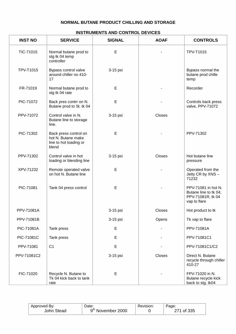
Approved By:John Stead
Date:9th November 2000
Revision:0
Page:271 of 335
NORMAL BUTANE PRODUCT CHILLING AND STORAGE
INSTRUMENTS AND CONTROL DEVICES
INST NO SERVICE SIGNAL AOAF CONTROLS
TIC-71015
TPV-T1015
FR-71019
PIC-71072
PPV-71072
PIC-71302
PPV-71302
XPV-71232
PIC-71081
PPV-71081A
PPV-71081B
PIC-71081A
PIC-71081C
PPV-71081
PPV-71081C2
FIC-71020
Normal butane prod tostg tk 04 tempcontroller
Bypass control valvearound chiller no 410-17
Normal butane prod tostg tk 04 rate
Back pres contrr on N.Butane prod to St. tk 04
Control valve in N.Butane line to storageline.
Back press control onhot N. Butane makeline to hot loading orblend
Control valve in hotloading or blending line
Remote operated valveon hot N. Butane line
Tank 04 press control
Tank press
Tank press
C1
Recycle N. Butane toTk 04 kick back to tankrate
E
3-15 psi
E
E
3-15 psi
E
3-15 psi
E
E
3-15 psi
3-15 psi
E
E
E
3-15 psi
E
-
-
-
Closes
-
Closes
-
-
Closes
Opens
-
-
-
Closes
-
TPV-T1015
Bypass normal thebutane prod chilletemp
Recorder
Controls back pressvalve, PPV-71072
PPV-71302
Hot butane linepressure
Operated from theJetty CR by XNS –71232
PPV-71081 in hot N.Butane line to tk 04;PPV-71081R, tk 04vap to flare
Hot product to tk
Tk vap to flare
PPV-71081A
PPV-71081C1
PPV-71081C1/C2
Direct N. Butanerecycle through chiller410-27
FPV-71020 in N.Butane recycle kickback to stg. tk04

Approved By:John Stead
Date:9th November 2000
Revision:0
Page:272 of 335
NORMAL BUTANE PRODUCT CHILLING AND STORAGE
INSTRUMENTS AND CONTROL DEVICES
INST NO SERVICE SIGNAL AOAF CONTROLS
PPV-71020
PNS-71081
PIC-71313
HIC-71193
HPV-71193
PNS-71081
Butane recycle kickback to tank line controlvalve
Tank press controlswitch
(on tank 04)
Butane to loadingrecycle to tank 04 (JettyCR)
Spillback from butaneto loading line to tk 04(operated from JettyCR)
Shutdown switch for N.Butane E loadingpumps, circ pumps, hotand hot loading pumps.Blocks in Suct valveXEV 71404
3-15 psi
E
3-15 psi
E
3-15 psi
Opens
-
Opens
Opens-
Butane recycle totank 04
PPV-71313,cooldown butanereturn from Jetties
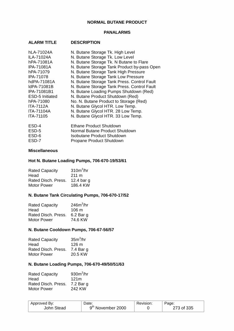
Approved By:John Stead
Date:9th November 2000
Revision:0
Page:273 of 335
NORMAL BUTANE PRODUCT
PANALARMS
ALARM TITLE DESCRIPTION
hLA-71024A N. Butane Storage Tk. High LevellLA-71024A N. Butane Storage Tk. Low LevelhPA-71081A N. Butane Storage Tk. N Butane to FlarelPA-71081A N. Butane Storage Tank Product by-pass OpenhPA-71079 N. Butane Storage Tank High PressurelPA-71078 N. Butane Storage Tank Low PressurehdPA-71081A N. Butane Storage Tank Press. Control FaultldPA-71081B N. Butane Storage Tank Press. Control FaultlPA-71081B1 N. Butane Loading Pumps Shutdown (Red)ESD-5 Initiated N. Butane Product Shutdown (Red)hPA-71080 No. N. Butane Product to Storage (Red)lTA-7112A N. Butane Glycol HTR. Low Temp.lTA-71104A N. Butane Glycol HTR. 28 Low Temp.lTA-71105 N. Butane Glycol HTR. 33 Low Temp.
ESD-4 Ethane Product ShutdownESD-5 Normal Butane Product ShutdownESD-6 Isobutane Product ShutdownESD-7 Propane Product Shutdown
Miscellaneous
Hot N. Butane Loading Pumps, 706-670-19/53/61
Rated Capacity 310m3/hrHead 211 mRated Disch. Press. 12.4 bar gMotor Power 186.4 KW
N. Butane Tank Circulating Pumps, 706-670-17/52
Rated Capacity 246m3/hrHead 106 mRated Disch. Press. 6.2 Bar gMotor Power 74.6 KW
N. Butane Cooldown Pumps, 706-67-56/57
Rated Capacity 35m3/hrHead 126 mRated Disch. Press. 7.4 Bar gMotor Power 20.5 KW
N. Butane Loading Pumps, 706-670-49/50/51/63
Rated Capacity 930m3/hrHead 121mRated Disch. Press. 7.2 Bar gMotor Power 242 KW
Approved By:John Stead
Date:9th November 2000
Revision:0
Page:274 of 335
PUMP SERVICES:
Hot N. Butane Loading Pumps;706-670-19/53/61.
Take suction 10" laterals off the 18" suction header from tk. Discharges through 8" dischargelaterals to main 10" discharge header to glycol heaters, 410-26 and 30, and from there to JettiesNo. 3, 6, 7 and 8.
N. Butane Tank Circulating Pumps, 706-670-17/52.
Take suction through 10" laterals off the 18" suction header from tank. Discharge through 8"laterals to 8" discharge header to go through either the heater, 410-27, or chiller, 410-17 with theexcess spilling back to the tank.
N. Butane Cooldown Pumps, 706-670-56/57.
Take suction through 4" laterals off of the 36" loading pump suction header. Discharge through3" line back to the discharge laterals off of each butane loading pump.
N. Butane Loading Pumps, 706-670-49/50/51/63.
Take suction from 36" suction header through 16" laterals. Discharge through 12" discharge.
Laterals into the 24" loading line to Jetties No. 3 and 4.
Approved By:John Stead
Date:9th November 2000
Revision:0
Page:275 of 335
PRE-STARTING INSTRUCTIONS
1. Clean-up the unit and check the auxiliary piping to see that it is installed properly. Ifpossible, install a suction strainer.
2. Check the piping. Make a thorough inspection of all piping including strainers, if installed. Also check auxiliary piping such as seal liquid and cooling water piping.
3. Check the alignment. See alignment and coupling instructions.
4. Check the driver rotation before coupling to the pump to make certain that it will rotatein the same direction as indicated by the arrow on the pump.
5. Mechanical seal - refer to seal drawing and G.A. drawing.
STARTING THE PUMP
Use the following procedure:
1. PRIMING.
Before starting a centrifugal pump, the casing and suction piping must be completelyfilled with liquid. The rotating parts within the pump depend upon this liquid forlubrication and may seize if the pump is operated dry.
2. If used, turn on cooling water services and sealing liquid to the stuffing box.
3. Close the discharge vale, if it is not already closed, and check theat the suction valve isfully open. Sometimes it is helpful to slightly crack the discharge valve to help providefor the removal of vapours at start-up.
4. Start the driver. As soon as the pump is up to rated speed, open the discharge valvesslowly to avoid abrupt changes in velocity and surging in the suction line. DO NOTOPERATED THE PUMP AGAINST A CLOSED DISCHARGE VALVE FOR ANYLENGTH OF TINE, as the liquid in the pump will be heated until it vapourises. This willcause your pump to seize by running dry.
5. Check for vibration. Vibration indicates improper alignment, and the unit should be shutdown and realigned.
6. Check for any increase in pressure drop across the suction screen, if used. The screenshould be cleaned if such a drop occurs. Leave the screen in the line for 24 hoursbefore removing.
Approved By:John Stead
Date:9th November 2000
Revision:0
Page:276 of 335
OPERATION
LOCATING TROUBLES IMPORTANT - First check ratings shown on pump nameplate.
FAILURE TO DELIVER LIQUID Pump not primed.Insufficient speed.Impeller or suction strainerplugged up.Wrong direction of rotation.Air leaking into suction.
PUMP LOSES PRIME AFTER STARTING Leaky suction line.
Air or gases in liquid.Liquid seal line plugged.Opening of discharge valve toorapidly.
MOTOR RUNS HOT Head lower than rating - pumping
too much liquid.Liquid pumped of greater specificgravity or viscosity than that forwhich motor is rated.Rotor binding.Defective motor.Lack of ventilation.Low voltage.Impeller rub.
INSUFFICIENT CAPACITY AND PRESSURE Air leaks in suction line or stuffing
boxes.Speed too low.Head higher than pump rating.Impeller or suction strainerpartially plugged.Insufficient suction head for hotliquids or volatile liquids.Mechanical defects:Wearing ring worn.Impeller damages.
PUMP VIBRATES OR IS NOISY Misalignment.
Foundation not sufficiently rigid.Impeller partially plugged, causingunbalance.Mechanical defects in pump ordriver:Shaft bentRotating element out of balance.Worn bearings.Rotating elementbinds.Suction or discharge pipe notanchored.Vapour-bound (pump noisy)
Approved By:John Stead
Date:9th November 2000
Revision:0
Page:277 of 335
OPERATION
LOCATING TROUBLES
IMPORTANT - First check ratings shown on pump nameplate.
FAILURE TO DELIVER Pump not primed. LIQUID Insufficient speed.
Impeller or suction strainerplugged up.Wrong direction of rotation.Air leaking into suction.
PUMP LOSES PRIME AFTER Leaky suction line.STARTING Air or gases in liquid.
Liquid seal line plugged.Opening of discharge valve toorapidly.
MOTOR RUNS HOT Head lower than rating-pumping toomuch liquid.Liquid pumped of greater specificgravity or viscosity than that forwhich motor is rated.Rotor binding.Defective motor.Lack of ventilation.Low voltage.Impeller rub.
INSUFFICIENT CAPACITY AND PRESSUREAir leaks in suction line or stuffingboxes.Speed too low.Head higher than pump rating.Impeller or suction strainer partiallyplugged.Insufficient suction had for hotliquids or volatile liquids.Mechanical defects: Wearingring worn.Impeller damages.
PUMP VIBRATES OR IS NOISY Misalignment.Foundation not sufficiently rigid.Impeller partially plugged, causingunbalance.Mechanical defects in pump ordriver:Shaft bentRotating element out of balance. Worn bearingsRotating element bindsSuction or discharge pipe notanchoredVapour-bound (pump noisy)
Approved By:John Stead
Date:9th November 2000
Revision:0
Page:278 of 335
INTRODUCTION
Nitrogen is a clear, odourless gas which makes up about 80% of the air around us. It is virtuallychemically inert and there are very few substances it will readily react with. Because ofnitrogen’s "inertness" it is widely used in the refinery and chemical industry to "blanket" or "purge"flammable and hazardous gases and liquids in drums, towers, pumps, compressors, pipelinesand tanks.
The large quantities of nitrogen required by industry is usually produced by liquefying air in aspecial compressor plant and then boiling off the oxygen. At atmospheric pressure oxygen boilsat -183ºC and nitrogen -196ºC.
The nitrogen supply for the Seal Sands Terminal will be delivered in Liquid form, carried byspecial low-temperature (cryogenic) tankers.
The liquid nitrogen is stored in a specially constructed double walled drum. The space betweenthe drum walls is evacuated and insulated to maintain the low temperature in the liquid nitrogen,the storage pressure is around 12 Bar.
The storage drum has piping arranged to top or bottom fill. The piping is arranged on thestorage drum so that nitrogen gas or liquid can be drawn off from process requirements to thevaporiser/heater. The storage drum also has piping to drum off liquid or gas directly from theinner container.
The nitrogen vaporiser will have two heating coils. One large coil to vaporise/heat nitrogen forprocess requirements and a small coil to heat up nitrogen to maintain the operating pressureinside the storage drum.
It is envisaged that the heat source for the nitrogen vaporiser will be L.P. steam, the steam flowbeing controlled by the outlet nitrogen temperature of the vaporiser. Final details of the vaporiserlay out are still being discussed. (B.O.C. System drawing attached).
After the vaporiser, the nitrogen is split into two systems. The high pressure system of 11.7 barsto the jetty area and the low pressure system of 4.5 bars to the processing areas, the flares andNGL product storage tanks. (Diagram attached for system layout).
The 11.7 bar system is fed to the jetty area along a 4" pipeline after passing through a costingmeter number 61450. The main usage of nitrogen on the system is expected to be in loadingarm purging.
The 4.5 bar system is let down by pressure control valve through costing meter number 61449to the NGL product storage tanks, the NGL/utilities area and the stabiliser overheadcompressors, then through a third costing meter number 61448 to the stabilisers ground flaresand to the elevated flare.
Usage of nitrogen on the utilities and NGL area and stabilisers is foreseen as intermittent. Aconstant purge of 0.9 standard cubic metres per hour is required to the elevated flare flowsensor.
After the non-return valve on the nitrogen to the elevated flare flow sensor, there is anemergency nitrogen supply from high pressure bottles, this system will come into operationshould the nitrogen pressure to the flow sensor FNT 61824 be reduced.
In the utility area provision has been made to cross-connect the nitrogen system to the plant airsystem as an emergency measure, should the air system fail.
Approved By:John Stead
Date:9th November 2000
Revision:0
Page:279 of 335
This cross-connect is still under review at the time of writing.The typical arrangement for hard lines connected to equipment is a double block and bleedarrangement, and from utility and hose station the line is reduced to a ¾" line after a valve.
Although non-return valves are fitted in the nitrogen supply lines to major users, great case mustbe taken to ensure that any vessel is to be purged must be at a lower pressure than the nitrogensystem.
DISTRIBUTION
Equipment supplied:-HP System 11.7 barsBerths 3&4 loading armsCold vent knock-out drumsMetering stationsEstimated nitrogen usage = 30,720 cubic meters per annum.
LP System 4.5 barsPropane tank vapour compressorsPropane storage tanks plus 4 utility stations.Ethane storage tank plus 2 utility stationsEthane refrigeration compressorsEthane tank compressorsEthane refrigeration economiserEthane chillerPropane chillerPropane refrigeration compressors plus 3 utility stations (Air make-up crossover) under review
14 utility stations to NGL east and westStabiliser overhead vapour compressors plus 3 utility stationsIso-butane and normal butane tanks plus 7 utility stations
Through costing meter number 61448 to:-Ground flares plus 3 utility stationsThe stabiliser unitsElevated flare
Air contains approximately 80% nitrogen and approximately 20% oxygen.
Any equipment that has been nitrogen purged must be air tested for oxygen content before anyentry permit can be issued.
No work can be done on equipment that is being purged without ensuring that the worker hasa safe supply of clean breathing air.The former name of nitrogen was the Greek word AZOTE, meaning "an inability to support life".

Approved By:John Stead
Date:9th November 2000
Revision:0
Page:280 of 335

Approved By:John Stead
Date:9th November 2000
Revision:0
Page:281 of 335
GLYCOL SYSTEM
Due to very low temperatures dealt with in certain parts of the plant such as the RefrigeratedProduct storage and loading system operation where heat must be applied to very cold productsit is necessary to use a heating medium with a very low freezing point for the heaters. A 70%solution of ethylene glycol and condensed steam is used for this purpose because of its lowfreezing point, (-60�&)�DQG�KHDW�FDUU\LQJ�SXUSRVHV�
The system comprises of a Glycol surge tank, six Glycol transfer pumps, five Glycol heaters (forsix heat exchangers), transfer systems, steam and condensate system required for heat andsystem distribution piping.
Glycol is pumped from the surge tank with one or more of the transfer pumps through the shellside of the heater being used where is heated to 66ºC with 3.45 Bar g steam flowing through thetube side of the heater.
The Glycol transfer pumps can be started remotely from the Jetty Control room. Low glycoltemperature alarms is transmitted to both the Jetty and NGL Control Rooms. Pump "Running"or "Stopped" status indicators are indicated on all pumps in the Jetty Control Room but only onpumps 3,4,5 and 6 (706-670-68 is for a stand-by).
Glycol is pumped from the tank with one or more of the above mentioned pumps through theshell side of a heater where it is heated to 66ºC and 3.45 Bar g (steam flowing through the tubeside). The Glycol is then routed to its respective heater exchanger (heater) where it flowsthrough the shell side for heating purposes. After passing through the heat exchanger it isreturned to the Glycol Surge Tank for re-use.
All of the pumps are identical, but no. 6, (706-670-68) which is piped up as the stand-by for anyof the others, as well as being used to recycle Glycol from the bottom of the tank through thepump and back to the top of the tank for mixing purposes. No. 4 and 5, (7060670-43/67) runconstantly.
Circulation System
Pump No. 706-670-40 supplies Glycol to heater no. 706-410-32 to Propane Storage LoadingHeater 706-410-29, plus transfers of Glycol to:
Cooling Water System Surge Tank make-upDe-methaniser tower Glycol Surge TankLPG Vaporiser (645-950-25)Glycol Expansion tank (645-950-17)4" Recycle back to the Glycol Surge Tank, 706-950-37
Pump No. (706-670-41) Supplies Glycol to Heater No. 706-410-32 for propane storage loadingheater - 706-410-32.Pump No. (706-670-42) Supplies Glycol to Heater no. 706-410-25 for the Iso-Butane tankRecirculating Heater.Pump No. (706-670-67) Supplies Glycol to Heater No. 706-410-28) for Butane StorageRecirculating Heater.Pump No. (706-670-670 Supplies Glycol to Heater No. 706-410-33 for the Normal Butaneloading Heater.Pump No. (706-670-68) - Stand-by pump for them all.
Temperature Control of the Glycol is made possible by utilising a temperature controller sensing
Approved By:John Stead
Date:9th November 2000
Revision:0
Page:282 of 335
the temperature of the outlet Glycol steam from each heater. (Each heater has its own controlsystem). The temperature controller adjusts the amount of steam needed by operating a controlvalve in the inlet steam line to each heater.
The condensed steam is collected in a common condensate accumulator and is pumped backto the condensate receiver at the Boiler House through a common pumped condensate line.
Approved By:John Stead
Date:9th November 2000
Revision:0
Page:283 of 335
EQUIPMENT DATA
Surge Tank - 706-950-37 the tank is a 4000 mm x 4600 mm atmospheric tank with a capacityof 58m3. Design pressure is 20m Bar g and -6m Bar g. A two inch condensate make-up isprovided for adding water. The Glycol fill line is a 2" on top of the tank. The tank has a dip stockand level indicator (L1-71111), and a locally mounted temperature indicator (Ti-71152). A 10"suction, and 8" return line is provided.
GLYCOL CIRCULATION PUMPS Six pumps are provided. All six are identical.Capacity - 70M3/MHeat - 42MDisch. Press. - 4.35 Bar-gDRIVER - 18.6 k.w. electric motor
HEATERS706-410-22/32/25Duty 2.65Surface Area 34M2
Design pressure 6.9 Bar gDesign temp. 93.0ºCDesign pressure 5.2 Bar gDesign temp 288ºC
706-410-28/33Duty 2.07 mwSurface Area 25.5m2
Design pressure 6.9 Bar gDesign temp. 93.0ºCDesign pressure 5.17 bar gDesign temp 288ºC
Condensate Pumps (2) (706-670-69/70)Capacity 23M2/hrHeat 57MDisch. 6.07 Bar gDriver 11.2 K.W.
Condensate Accum. (706-950-53)DIA 1100 mmLength 2200 mmDesign Press. 5.2 Bar gDesign Temp. 250ºC

Approved By:John Stead
Date:9th November 2000
Revision:0
Page:284 of 335
Control No. Location Valve No. Service
TIC-71106 Local TPV-71106 Heater No. 706-410-22 SteamTIC-71100 " TPV-71100 Heater No. 706-410-32"TIC-71102 " TPV-71102 Heater No. 706-410-25"TIC-71104 " TPV-71104 Heater No. 706-410-28"TIC-71105 " TPV-71105 Heater No. 706-410-33"
HNS-71242 Jetty C.R. Pump No. 706-670-40HNS-71242 " Pump No. 706-670-41HNS-71243 " Pump No. 706-670-42HNS-71244 " Pump No. 706-670-43HNS-71245 " Pump No. 706-670-67HNS-7246 " Pump No. 706-670-68
LNS-71150 Local Cond. Low Level - shuts down 706-670-69/70LC-71157 " LPV-71157 - Cond. Accum. liquid level.
Relief Valves
Number Size Set Press. Service
PSV-71097 ¾" x 1" 6.9 Bar-g Glycol Heater - 706-410-22PSV-71098 " " Glycol Heater - 706-410-32PSV-71095 " " Glycol Heater - 706-410-25PSV-71096 " " Glycol Heater - 706-410-28PSV-71088 " " Glycol Heater - 706-410-33
ALARMS IN The NGL CONTROL ROOM
Number Service Location
ITA-71106A- Low Glycol Temp. from heater 706-410-22ITA-71100A Low Glycol Temp. from heater 706-410-32ITA-71102A Low Glycol Temp. from heater 706-410-25ITA-71104A Low Glycol Temp. from heater 706-410-28ITA-71095A Low Glycol Temp. from heater 706-410-33

Approved By:John Stead
Date:9th November 2000
Revision:0
Page:285 of 335

Approved By:John Stead
Date:9th November 2000
Revision:0
Page:286 of 335
Automatic Restarting of Electric Drives Following Power Outages
TEESSIDE PLANT
A certain number of electric motor starters are equipped with restarting relays. One of the relays"remembers" which motor was running before the power outage. The other relays act as a"start" relay.
The memory relay is adjustable from 0 to 30 minutes. At this writing, it is set at 15 minutes forUtilities, Stabilisers and one motor on the Jetties. It is set at 8 minutes for the NGL Area.
If power is not restored within the setting of the memory relay, all motors have to be restartedmanually.
The "start" relay is also adjustable. The range is 0 to 70 seconds. this relay starts a limitednumber of motors at a time. The most critical drives re-start 2 seconds after power is restored. The next step is 5 seconds followed by the 11, 25, 40, 55 and 70 seconds steps. The steppedre-starting will prevent the tripping of main circuit breakers.
Motors that are controlled by process switches (pressure, flow, temperature level) generally donot have re-starting relays. These motors can be identified by their start-off - auto switches. when the switch is in "Auto" the process device starts the motor. If the selector switch is in the"Start" position, it will immediately re-start automatically following a power dip. The "Start"position overrides the process switch. The "Start" position is primarily for testing andmaintenance.
Some of the large drives that have start-off-auto switches (e.g. Boiler feed Water Pump_ havea time delay on restarting following a power outage.
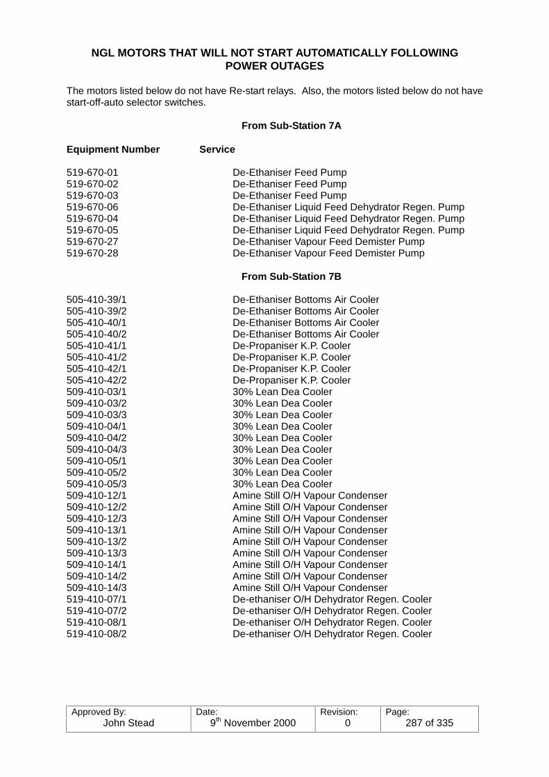
Approved By:John Stead
Date:9th November 2000
Revision:0
Page:287 of 335
NGL MOTORS THAT WILL NOT START AUTOMATICALLY FOLLOWINGPOWER OUTAGES
The motors listed below do not have Re-start relays. Also, the motors listed below do not havestart-off-auto selector switches.
From Sub-Station 7A
Equipment Number Service
519-670-01 De-Ethaniser Feed Pump519-670-02 De-Ethaniser Feed Pump519-670-03 De-Ethaniser Feed Pump519-670-06 De-Ethaniser Liquid Feed Dehydrator Regen. Pump519-670-04 De-Ethaniser Liquid Feed Dehydrator Regen. Pump519-670-05 De-Ethaniser Liquid Feed Dehydrator Regen. Pump519-670-27 De-Ethaniser Vapour Feed Demister Pump519-670-28 De-Ethaniser Vapour Feed Demister Pump
From Sub-Station 7B
505-410-39/1 De-Ethaniser Bottoms Air Cooler505-410-39/2 De-Ethaniser Bottoms Air Cooler505-410-40/1 De-Ethaniser Bottoms Air Cooler505-410-40/2 De-Ethaniser Bottoms Air Cooler505-410-41/1 De-Propaniser K.P. Cooler505-410-41/2 De-Propaniser K.P. Cooler505-410-42/1 De-Propaniser K.P. Cooler505-410-42/2 De-Propaniser K.P. Cooler509-410-03/1 30% Lean Dea Cooler509-410-03/2 30% Lean Dea Cooler509-410-03/3 30% Lean Dea Cooler509-410-04/1 30% Lean Dea Cooler509-410-04/2 30% Lean Dea Cooler509-410-04/3 30% Lean Dea Cooler509-410-05/1 30% Lean Dea Cooler509-410-05/2 30% Lean Dea Cooler509-410-05/3 30% Lean Dea Cooler509-410-12/1 Amine Still O/H Vapour Condenser509-410-12/2 Amine Still O/H Vapour Condenser509-410-12/3 Amine Still O/H Vapour Condenser509-410-13/1 Amine Still O/H Vapour Condenser509-410-13/2 Amine Still O/H Vapour Condenser509-410-13/3 Amine Still O/H Vapour Condenser509-410-14/1 Amine Still O/H Vapour Condenser509-410-14/2 Amine Still O/H Vapour Condenser509-410-14/3 Amine Still O/H Vapour Condenser519-410-07/1 De-ethaniser O/H Dehydrator Regen. Cooler519-410-07/2 De-ethaniser O/H Dehydrator Regen. Cooler519-410-08/1 De-ethaniser O/H Dehydrator Regen. Cooler519-410-08/2 De-ethaniser O/H Dehydrator Regen. Cooler

Approved By:John Stead
Date:9th November 2000
Revision:0
Page:288 of 335
From Sub-Station 7C
Equipment Number Service
505-670-41 Methanol Injection Pump505-670-42 Methanol Injection Pump505-670-41/42 Methanol Injection Pump505-410-18/1 Iso-butane Cooler505-410-18/2 Iso-butane Cooler505-410-19/1 Iso-butane De-propaniser Col. OHV Condenser505-410-19/2 Iso-butane De-propaniser Col. OHV Condenser505-410-19/3 Iso-butane De-propaniser Col. OHV Condenser519-410-12/1 Butane Dehydrator Regen. Cooler519-410-12/2 Butane Dehydrator Regen. Cooler519-410-12/3 Butane Dehydrator Regen. Cooler519-410-17/1 Propane Dehydrator Regen. Cooler519-410-17/2 Propane Dehydrator Regen. Cooler519-410-18/1 Propane Dehydrator Regen. Cooler519-410-18/2 Propane Dehydrator Regen. Cooler
From Sub-Station 8A (415 Volt Motors)
706-050-03 Ethane Tank Blower706-050-03 Ethane Tank Blower706-670-10 N-Butane Blend Pump706-670-11 N-Butane Blend Pump706-670-12 N-Butane Blend Pump706-670-23 Isobutane Blend Pump706-670-24 Isobutane Blend Pump706-670-25 Isobutane Blend Pump706-670-525 Lube Oil Pump-Propane Compressor No. 706-160-19706-670-527 Lube Oil Pump-Propane Compressor No. 706-160-21706-670-67 NGL Storage Glycol System Pump706-410-522 Ethane Tank Blower Lube Oil Cooler Fan706-410-523 Ethane Tank Blower Lube Oil Cooler Fan706-670-68 NGL Storage Glycol System Pump (May Change)706-670-69 Condensate Pump706-670-70 Condensate Pump
From Sub-Station 8A (3.3kv motors)
706-670-49 N-Butane Loading Pump706-670-50 N-Butane Loading Pump706-670-51 N-Butane Loading Pump706-670-63 N-Butane Loading Pump706-670-47 Hot Iso-Butane Loading pump706-670-04 Propane Loading Pump706-670-05 Propane Loading Pump706-670-06 Propane Loading Pump706-670-44 Propane Loading Pump706-670-45 Propane Loading Pump706-670-13 Isobutane Loading Pump706-670-14 Isobutane Loading Pump706-670-15 Isobutane Loading Pump706-670-65 Isobutane Loading Pump706-160-19 Propane Tank Compressor

Approved By:John Stead
Date:9th November 2000
Revision:0
Page:289 of 335
706-160-20 Propane Tank Compressor706-160-21 Propane Tank Compressor706-670-07 Hot Propane Loading Pump706-670-46 Hot Propane Loading Pump706-670-60 Hot Propane Loading Pump706-670-19 Hot Butane Loading Pump706-670-48 Hot Butane Loading Pump706-670-53 Hot Butane Loading Pump706-670-61 Hot Butane Loading Pump706-670-01 Ethane Loading Pump706-670-02 Ethane Loading Pump
From Sub-Station 8B (415 volt)
None None

Approved By:John Stead
Date:9th November 2000
Revision:0
Page:290 of 335
PURPOSE
To describe re-starting and control of Fan Motors.
Two Speed with Automatic Control
With the Start-Off-Auto selector in Auto position the fan will change from low to high or high tolow speed as dictated by the temperature or pressure switches. The fans will start automaticallyfollowing power dips at the speed called for by the process switches.
With the Start-Off-Auto selector switch in Start position the fan will run when either the slow orfast button is pushed. To change from slow to high or high to slow speed the off button must bepushed then re-set then the desired speed button pushed. It will be helpful if the operator willwait about 10 seconds between the gas and slow selections.
The fans will not restart automatically following power dips.
Two Speed with Manual Control
The operator pushes the desired slow or fast push button.
the off button must be pushed and re-set when changing from one speed to another. It will behelpful if the operator will wait about 10 seconds when changing from fast to slow speed. Thefan will not re-start automatically following a power dip.
If the fan also has a Slow-Off fast push button in the control room, the off push button can bepushed one to stop the fan, then immediately pushed again to re-set the switch so it can nextbe started at the local station if desired.
Single Speed with Manual Control
The fan will re-start automatically following a power dip. All of the fans are programmed to re-start after about a 70 second delay following power restoration.
Control room stop buttons cannot be re-set until the re-start timer has timed out, about 15minutes.
Respectfully submitted.
E.T. Crimmins24th August, 1977

Approved By:John Stead
Date:9th November 2000
Revision:0
Page:291 of 335
EMERGENCY ELECTRICAL POWER
A. Emergency and Non-Interrupted and Electrical Power Supplies
The majority of panel instruments and field transmitters at Seal Sands require 24 voltsDC supply.
Each of the four main Control Rooms are equipped with battery units designed from aminimum 2 hours working capacity during loss of mains power.
The battery charger is maintained via a rectifier unit powered from adjacent sub-stations. Each battery/rectifier assembly is duplicated for maintenance etc., and security of supplyis increased by auto changeover switches between each unit.
The 110 volt DC power is used for essential instruments indication/alarm units andanalysers supplied from battery backed static inverters, and is designed for a minimumof 1 hour working capacity in case of loss of mains power. the battery charger, like the24 volt DC system, is maintained via a rectifier unit powered either from a sub-station orthe emergency generator, which is switched over to automatic.
Each Control Room is equipped with one inverter/battery/rectifier unit with facility for by-passing with 415/110 volt transformer for maintenance or emergency operation.
Solenoid operated valves and shutdown devices, etc. requiring 110 volts DC are suppliedfrom individual battery units at each Control Room, and are designed for a minimumworking capacity of 2 hours should a power failure occur. The battery charger ismaintained from rectifier units supplied from adjacent sub-stations. Each battery/rectifierassembly is duplicated for maintenance etc., and security of supply is increased by autochangeover switches between each unit.
An additional battery/rectifier unit is installed at the Utility Control Room to furnish powerto the propane compressor control panels and cranking motor batteries.
The diesel driven fire pumps cranking devices, emergency lighting, PABX telephones,radio paging and microwave equipment batteries are charged from the mains.
The lights have a 1 hour working duration, 7 hours for the PABX telephone system, and10 hours for the radio paging and micro-wave equipment.
B. Emergency Generator and Turbine
During a general power failure, the Emergency Generator is automatically started, andthe following equipment will be diverted to its supply as follows:
a. Rectifier/chargers for the 110 volt inverters.b. Rectifier/charger for radios, paging and microwave equipment.c. Rear and front leading lights (THPA).d. Maintenance telephones.e. Control Rooms emergency lighting.f. Lube oil pumps for the boiler feed water turbines (3).g. Pre-lube pumps for the air compressors.h. Lube oil pumps for boiler fuel circulating pump (1).i. Lube oil pumps for firewater turbine (1).j. Lube oil pumps for cooling water turbines (3).k. Auxiliary hydraulic pumps for the propane compressors.
The following items of equipment have duplicated feeds with automatic changeover
Approved By:John Stead
Date:9th November 2000
Revision:0
Page:292 of 335
switches:a. Instrumentation at Greatham Control Room from sub-station 9A.b. Navigation lights and fog bell at Jetty No. 2c. All rectifier charger units associated with items 1-4.
The Emergency Generator is rated as follows:290 KVA 415/240 volts.3 phase-4 wire 50 H2
0.8 power factorSteam conditions: 17.28 Bar G/260�&�DWPRVSKHUH
The turbine driver is a Coppus RL 23L single stage impulse type, two row velocity stagewheel with a row of stationery reversing blades between the two rows of rotating blades.
It is equipped with hand valves on some of the steam nozzles for partial load or overloadconditions.
A Sentinel Relief to warn of exceptional back pressure on the turbine casing is provided.
A safety trip is provided that closes the steam valve if the rpm exceed the rated speedby 20%.
The turbine is started automatically from power interruption from:
NGL Control RoomUtilities Control RoomStabiliser Control RoomJetty Control RoomMotor Starter Board at Utilities Control room
The emergency generator start is automatic and will be initiated by the opening of anyone of the remote contacts which will operator separate latching type 110 volt DC relayswithin the panel. (As long as there is power going through the solenoid, it will remain ina closed position - but will fly open the second the power is lost. The emergencygenerator turbine is tripped off from a "NO VOLT" signal). A separate indicator lampswitched by each relay will show which area initiated the start. A common "generatorstart" relay is also operated by the above relays. The start relay will control the steamvalve, Control Room lamp and generator and control panel anti-condensation heaters.
It is possible to have a power failure in one place only, and the Emergency Generator willstart and provide power for that section only.
Resuming power will switch the system back over to normal, but the EmergencyGenerator turbine must be shutdown manually and re-set by means of front of panel re-sets for the latching relays.
When the "test" start-up is operated, the machine will only stop when the switch isreturned to the auto stand-by position.
The Emergency Generator and turbine is locate don the north side of the north boilerfeedwater pump.
A differential pressure recorder is provided to measure the difference of pressurebetween the bottom of the column and the overhead vapour line (dPR-51128).
Approved By:John Stead
Date:9th November 2000
Revision:0
Page:293 of 335
Accumulator Pressure: Pressure on the accumulator is controlled by PIC-51135 whichcontrols the accumulator back pressure control valve PPV-51135 located in the 6"overhead vapour line off the top of the vessel. The pressure sensing point is located onthe accumulator (PNT-51135).
Column Temperature Control - Temperature required for proper separation is controlledby either of two types of control (1) Conventional tray temperature control, or (2) by DCS(Advanced Control)
Tray Temperature Control - with this type of control the temperature of tray no. 20 is usedas the control point. Temperature here is transmitted to a temperature controller, TIC-51125 where the signal is then sent out to the bottom product flow control valve - FPV-51032 (which is also the feed control valve to the De-propanizer Column down stream).The kettle flow affects the level of the liquid in the bottom of the De-ethaniser which issensed by the kettle liquid level control LIC 51070. This resets FIC-51033 which in turn(through FNX-51033) controls the amount of steam through the steam control valve,FPV-51033 located in the main 12" steam line to the reboilers, to reboil the correctamount of liquid to hold the level constant.
Bottom Product - The bottom product rate is on flow control, FPV-51032, which is resetby conventional temperature control sensed from 20th tray, or by DCS (AdvancedControl). Column valves are situated on the Depropanisers near the feed entry on thetower, their by-pass valves are power operated by hand controllers, HPV-51010/51012located on the panel board.
Distillation Column Control - Chromatograph analysers are provided to analyse thetop/bottom product composition. This information, plus input signals from DynamicMatrix Control (Advanced Control) ensure bottom and overhead product specificationsare achieved/maintained. Further details are contained in the DCS training manual.
Overhead Vapour Product is the result of the actions of the accumulator back pressurecontrol valve PC51135 - to hold the accumulator pressure constant.
Reflux Accumulator Level Control - is achieved by LC51078 resetting TC51129(A and B valves) - the accumulator level will normally be 50%.
If the level begins to rise more vapour flow will be directed through the TC51129B valveto warm up the accumulator and hence lower the level and increase the vapour flow tothe DEA units. Conversely, if a level increase is required in the accumulator more vapourwill be directed through the ’A’ valve, condensing more vapour increasing the liquid level.
f. Alarms and Safety Equipment
The control valves throughout the De-ethaniser systems are designed to "fail safe"; thatis, with loss of instrument air or electricity the control valves will open or close asnecessary to block in the feed and product streams, shut off the steam, allow overheadvapour to flow through the overhead vapour condenser, and liquid to be pumped backto the column if the reflux pump is still operating.

Approved By:John Stead
Date:9th November 2000
Revision:0
Page:294 of 335
Start up preparation and guidelines
The Demethaniser operation relies on a variety of essential systems and plant conditions. As theDemethaniser is at the "end off" the light ends separation section it will logically be the lastprobable item to be commissioned in this system. The following general criteria must be fulfilledto enable Demethaniser commissioning and operation.
1. The Demethaniser and associate plant must be ex maintenance deblinded and be leaktested with specifically either an inert nitrogen atmosphere or light hydrocarbonatmosphere. All plant being dry with no free water and dew points around the system of-40ºC or better.
2. Propane LS refrigeration must be commissioned and available with the DeC1 feed chillersystem being established - initial temperature control values being approximately -17ºC.
3. Ethane refrigeration overheads chilling should be under ethane as a minimum with themain sections of the Ethane refrigeration system being in commission and steady. Theoverheads chilling system can be difficult to control in no load situation and prematurefilling of this system can create significant C2 refrigeration system problems.
4. Ideally two regeneration dry overheads dehydrator beds should be available with a supplyof treated gas for start up available at between 5000 and 8000m3/hr. Surplus potentialfeed can quite easily be routed into fuel to control the start up feed rate.
Safety Consideration
The following items are over and above the other "normal" requirement items for safety start upof any plant i.e. they are distinct extra areas relating to this system.
1. The Demethaniser overhead vapour export to fuel via the normal feed to overhead exportheat exchangers must always be monitored with care in the start up phase -temperatures of the vapour export ex the accumulator can fall to the -74ºC are (normalaccumulator temperature). If this vapour is not warmed up against incoming feed gasesin the heat exchangers dangerously low temperatures could result in the fuel gas exportpiping which is only designed for -40ºC max!. Fracture of piping downstream could resulti.e. no low temperature gas export from the accumulator is permissible to fuel gaswithout "warm" feed gas being available to warm it up.
2. Demethaniser bottoms yield cannot be flared in the conventional way due to the extremelow temperatures attainable by its "flashing" down consequently a special dump tank isavailable to this product capable of handling ethane at -90ºC. The vapours from thisvessel are routed to the cold ground flares. The capacity of the dump tank is limited andalternate disposal/routing is necessary if problems are of an extended nature eg. fuellingis a good option.
3. System temperature of lower than -70ºC are found in the system physical contact withany cold piping or actual product can result in severe cold burns/frostbite.
General
The Demethaniser is an extremely flexible column being capable of handling feedrates from8000 - 3600m3/hr+. Similarly it can be run in a flexible manner e.g. varied feed chillingtemperature.
Approved By:John Stead
Date:9th November 2000
Revision:0
Page:295 of 335
Start up
With the system lined up and proved leak tight/purged, feed can be admitted via the feed chillerexchanger with the temperature control set at -17ºC. The feed gas must be dry and of normalcomposition. Control feedrate in the range 5000 - 8000m3/hr to condition and purge the columnand its ancillaries. Allow the system pressure to slowly rise toward the 14-15 bar g operatingpressure area. Bleed vapours to the CVH from the accumulator PSV bypass and from theaccumulator pump drains to control this pressure. Advise the Stabiliser CCB panel of flaringactivities via this route. Check the entire system for leaks and monitor internal temperatureprofile of the column. Hot glycol circulation should be applied sparingly to the reboiler in theearly phase of start up until a consistent bottoms level is visible. Chilling down of the towerinternals coupled with the increase in the system pressure will result in liquid ethane condensing. The ethane refrigeration to the overheads chiller can be commissioned once the column chillingdown has levelled off-aim for a gradual steady reduction in system temperatures in the columnand its piping fall continue to monitor the system for potential leakage. Care in thecommissioning of the overheads ethane refrigeration is essential if upset to the refrigerationloops is to be avoided. As the accumulator chills down a liquid level will become apparent -ensure the expected duty reflux pump and its piping are chilled down by bleed off from the pumpdrain to the CVH. When adequate bottoms level is present the export loop can readied -similarly the overhead export to fuel can be prepared. Once analysis is proven satisfactory bylaboratory analysis feedrates and exports can be established. As the tower rates increase thefeed chiller temperature can be progressively reduced toward its normal operating value furtherloading up and chilling the column to produce normal internal tray loading/system DP andtemperature profile.
System Shut Down
Shut down of the Demethaniser is the reverse of the start up in that a slow and gradual warmup and depressure are required. Once feed is stopped liquid export should continue till thebottoms pumps show initial cavitation signs - then shut them down. The accumulator levelshould be reduced to a minimum about one hour before shut down and the overhead chillerbypass HIC brought into play to recover as much to fuel export as possible prior to stoppingcolumn feed. Once exports have ceased fold system pressure and drain all liquid from thebottom and from the accumulator systems. System pressure greatly aids this activity - monitortemperature profiles and slowly depressure the tower via the bottoms to dump tank route andthe accumulator via the PSV bypass route- CAUTION - monitor temperatures closely to ensure that no drastic reductions are evident dueto residual liquids flashing off. Once the system is at vent pressure commission a moderate flowof nitrogen - monitor warm up-complete isolation lists etc.

Approved By:John Stead
Date:9th November 2000
Revision:0
Page:296 of 335
Approved By:John Stead
Date:9th November 2000
Revision:0
Page:297 of 335
6. BUTANE TREATER/DEHYDRATOR TREATING SYSTEM:53-T-33/34/35/36/37P & ID Ref: 7809-519-D00-005
A The Butane treater receives mixed as its feed from the bottom product of thedepropanizer Fractionating towers, and removes the water and sulphur compounds toprovide a suitable product for refrigerated storage and sales.
Specifications for the treated butanes are: 2 ppm maximum, and volatile sulphurcompounds 15 grains/100 cu’. The water specifications are required to prevent freezeups when the temperatures are reduced to permit storage in atmospheric pressuresrefrigerated storage tanks, and the sulphur must be reduced so that it can meet salesspecifications.
The systems required for this operation include the following equipment:-
(1) Two Butane Dehydrator Feed Pumps (53-p-09/10)(2) Five Butane Treating Towers (53-T-33/34/35/36/37)(3) One Butane Dehydrator Regeneration Separator (53-D-38)(4) One Butane Dehydrator Regeneration Cooler (53-E-12)
(One of the Propane Treater Coolers is connected as a common spare).(5) Two Butane Dehydrator Regeneration Separator Pumps (53-P-11/12)(6) Two sets of Regeneration Gas Heaters (53-E-15/16/19/20/21/22)
The system begins with the Dehydrator Feed Surge Tank and ends, for the liquid stream,at the inlet to the Depropanizer Kettle product heat exchanger. The regeneration gassystem ends with the back pressure controller on the line to the feed system.
Flow Description The wet liquid mixed butanes flow from the bottom of the depropanizertowers through the shell side of the DEC-3 kettle product heat exchangers 53-E-30/31/32/33 and out through a 6" line into an air fin cooler (5-E-41) where it is cooled toaround 38oC. It is then routed through a 4" line through the Depropanizer bottomsproduct control valve where it joins up with the No. 2 Depropanizer bottoms product. Thecombined streams enter a 6" line from this point on into the Butane Treater Surge Tank.
The liquid from the surge tank is then pumped tot he treaters on line where it enters thebottom, flowing upwards through the beds where it makes contact with the ALUMINAballs and MOL SIEVE fill material. Moisture and sulphur is removed in this process byabsorption in the beds. The liquid then flows out of the top of treaters into a commonoutlet header where it is routed through the tube side of the Depropanizer kettle productheat exchangers described above and on out to become the feed for the butane splittercolumn. A continuous sulphur analyser (AR 51017) has been installed on the commonoutlet header, which will sound an alarm if the sulphur content of the butanes becomeshigh or if the analyser fails. Since water is more strongly absorbed by the desiccant thatsulphur compounds, the sulphur will break through long before the water. Consequentlyonly sulphur content is monitored to determine the effectiveness of treating anddehydration.
Regeneration As the Butane is being treated in the Treating Tower the desiccant isgradually being saturated with water and sulphur and will reach a point where it will nolonger function. It must then be taken off the line re-generated.
Regeneration is process of "cleaning up" the beds enabling them to be used again. Thisprocess is accomplished by taking a stream off of the High Pressure Fuel gas header(Demethaniser overhead gas), heating it to 316oC with superheated steam in the
Approved By:John Stead
Date:9th November 2000
Revision:0
Page:298 of 335
vaporisers and passing it through the beds from the top, and out the bottom. Theelevated Regeneration Gas temperature vaporises the moisture and sulphur from themol-sieves and sweeps them on out with the gas. The gas, along with the moisture andsulphur is then routed through an air fin condenser (53-E-12) where the temperature islowered to around 38oC (100oF) before entering the Regeneration Separator (53-D-28). The moisture is condensed, along with the heavier hydrocarbons and drops out to thebottom of the vessel where the water is drawn off (manually) and the liquid hydrocarbonsare pumped back to the feed tank. The Regeneration Separator is automatically pumpedback to the beds now on line. Tank (53-D-32) where it enters with the fresh feed comingin to the beds now on line. The feed tank has a Liquid level control that resets the feedto the Butane Splitter Tower which should maintain a level at all times, but is equippedwith a low level shut down switch in case of problems upstream of the Depropanizer,which will shut down the feed pump.
After the heating step has been completed the Bed must be cooled before putting it backin service. This is accomplished be taking a side stream of the liquid feed and pumpingit back through the Bed in an UPWARD flow. Part of this liquid will flash, or vapourizewhen it first hits the hot bed but will eventually cool down, condense in the condensingair fin condenser (53-E-12) and drop out in the bottom of the Regeneration Separator(like the heating step) and then be pumped back to the Feed Tank (53-D-32).
The Dehydrator Regeneration Pumps provide enough pressure to prevent any "flashing"of liquids in the Beds, which can damage the desiccant, as well as adequate pressureto get cooling Butane into the Regeneration Separator against the Regeneration Gaspressure even at times when the Feed Tank pressure is low. In order to properly feedthese pumps, the Feed Surge Tank (53-D-32) is provided at the Pump’s suction. Thistank has about 12 minutes of residence time when half full.
The Regeneration Separator (53-D-38) is made large enough to hold all the liquid fromone Treater/Dehydrator Tower and still provide for gas/liquid separation. This isdesigned this way so that the liquid in a tower can be pushed out by the RegenerationGas as fast as the gas comes in without regard to the pump-out rate from the separator.
Process Variables and Controls The primary process variables, such as feed to theTreaters temperature, pressure flow rate, water and sulphur content are controlled by theoperation of other units and cannot b directly changed at the Butane Treater. The Feedlow is controlled by a liquid level control on the Butane Treater Feed Tank, LIC-51263which re-sets the amount of feed going to the Butane Splitter Column. This results invarying the Butane Splitter column feed to maintain a working level in the Butane TreaterFeed Tank. The operator must, however, keep the feed equally distributed through theBeds by manually adjusting the inlet valves to the beds. The temperature of the Feedis a result of operations and conditions upstream of the Butane Treater.
During the Regeneration process the gas flow rate and temperature are the primaryvariables. The design regeneration gas flow rate is 8,000 NM3/Hr with tower inlettemperature of 315oC. If the regeneration gas flow rate, or temperature is too low, thedesiccant will not be completely regenerated. Upon initiation of the regeneration heatingcycle the outlet temperature will be low but will come up in stages as the bed isregenerated.
The heat for the Regeneration Gas is supplied by passing 55.2 Bar G steam through theshell side of the Regeneration gas vaporisers. The exit gas temperature is controlled bysplit range temperature controller TIC-51391 which receives its signal from temperaturetransmitters on the inlet gas to the bed, an outlet gas from the bed. The signal istransmitted to a steam bleed valve off the top of the vaporiser TPV-51331-B and a three-way control valve (TPV-51331-A) on the regeneration gas stream. The tree-way valvecontrols the relative amount of Regeneration gas flowing through or by-passing around
Approved By:John Stead
Date:9th November 2000
Revision:0
Page:299 of 335
the vaporiser. If additional heat is needed, with all gas going through the vaporiser, thesteam bleed valve (TPV-51331-B) vents steam off the super heater portion of thevaporiser thereby increasing the amount of heat available. During normal operation thethree-way valve is expected to be in control.
Cooling the Regenerated Bed is accomplished by pumping Butane Treater feed UPthrough the Bed.
Cooling During the cooling of the towers the butane flow and separator temperature arethe primary variables. The design flow rate of cooling butane is 5M3/hr with aRegeneration Separator temperature of 38oC. The flow rate is low enough that there isno danger of fluidizing the bed when all the butane vaporises as it will during the firs partof the cooling step. Higher flow rates could damage the bed, yet if the rate were too lowthe bed will not be sufficiently cooled. If the Regeneration Separator temperature ismuch above 38oC an excessive amount of dissolved water will recycle back from theseparator to the Feed Surge Tank, causing additional moisture to be removed with thebeds on stream. The Regeneration Separator temperature is normally controlled by thelouvres on top of the condensing coils, (53-E-12) automatically by a temperature sensingpoint (TE-51436) in the inlet line to the separator, which controls the louvres. Additionalcontrol is provided by having a two-speed motor driving the fans.
Any water accumulated in the Regeneration Separator will de drawn off manually to thedrain system.
The normal cycle for the towers is controlled by an automatic sequence timer. Since thesame source of regeneration gas is used for both the Butane, and Propane Treaters thetiming cycle for heating-cooling, etc. for both treaters must be inter-locked. The cycletimes cannot be altered on one Treater without being compensated on the other.
Automatic Sequencing Timer - the standard cycle for a tower is:ON STREAM - 24 hoursHEAT - 4 hoursCOOL - 4 hoursSTAND-BY - 4 hours
This is accomplished automatically with the "Automatic Sequence" timer which isprogrammed in such a manner as to open and close the valves required to have threetowers on stream, one bed regenerating (either heating or cooling) and one bed onstand-by.
The sequence of valve operation during a tower cycle is:STATUS Towers No. 5-T-33,34 and 35 on stream.
Tower No. 53-T-36 on stand-by.Tower No. 53-T-37 cooling.
NB. Because of the change in specification of the butane products the treaters are nowchanged over manually from the sequence controller sub panel.
Instructions for the frequency of changes will be issued on the daily operatinginstructions.
Valve Positions: Valves open: Main inlet and outlet vales for tower No. 53-T-33/34 and 35number XPV-51137,40,41,44,45,48 and outlet valve No. XPV-511488from tower No. 53-T-36 (stand-by); Regeneration valves No. XPV-51154and 55 on tower No. 53-T-37. Cooling Butanes valve No. XPV-51160 andXPV-51159, cooling regeneration gas line valves to air fins, andregeneration separator.
Approved By:John Stead
Date:9th November 2000
Revision:0
Page:300 of 335
Sequence No.1- Valve XPV-51149 opens, establishing Butane flow through Tower No. 453-T-36
Sequence No. 2- Valves XPV-51154/55/60 and 56 close, shutting cooling gas out of No.4tower, and valve No. XPV-51156 (53-T-37 tower main outlet) opens,placing it on stand-by condition.
Sequence No. 3- Main inlet and outlet valves (XPV-51140/XPV-51137) to No. 1 tower (53-T-33) close to take the tower off stream. At the same time, valves No. XPV-51138/39 open, as well as XPV-51158 which lines up the regenerationgas through the vaporiser and starts hot gas to the bed Regenerationthen commences.
Sequence No. 4- At the end of the heating cycle, valves No. XPV-51158/62 close, stoppingthe flow of hot regeneration gas through No. 1 tower 53-T-33.
Sequence No. 5- Valves No. XPV-51160/59 open, starting the flow of Butane UP throughthe bed to cool it.
Final StatusTower No. 2,3 and 4 (53-T-34/35 and 36).Tower No. 5 (53-T-37) - On STAND-BY.Tower No. 1 (53-T-33) - Cooling.
START-UP After purging has been done, and feed is available, start the steam system upthrough the steam side of the treaters, and start a regeneration cycle. After they have beenregenerated, and cooled, feed may be introduced.
1 Fill towers 1 through 4- (53-T-33-34-35-36) and the product line to the Butane Splitter withliquid butanes.
2 Close the inlet valves on towers 2,3 and 4.
3 Set the automatic sequencing controller to the start of the on-stream cycle forTower 1. Start butane flow through Tower 1 at a flow-rate no lower than 75gpm(this is to prevent bed "channelling").
4 Open block valves on Tower 5- (53-T-37). See that the automatic valve sequencingcontrol is on "AUTOMATIC".
5 Open the outlet block valve on Tower 4, to place it on "stand-by".
6 If after 8 hours the flow rate is below 150gpm, place Tower 2 on stream and close theinlet block valve on Tower 1.
7 If after 16 hours the flow rate is below 150gpm, place Tower 3 on stream and close theinlet block valve on Tower 2.
8 As soon as the flow rate is above 150 gpm, two towers may be placed on streamin parallel. If the flow rate is above 225 gpm, three towers may be placed onstream.
NOTE: For a detailed Description of the Automatic Valve Sequencing control for theButane Treaters, see under "Propane Treater/Dehydrator" section in thismanual.
Approved By:John Stead
Date:9th November 2000
Revision:0
Page:301 of 335
ELECTRICAL FAILURE
In case an electrical failure occurs, the regeneration gas cooler fans, Feed pumps, andRegeneration gas separator liquid pump will stop. All switching valves controller by theAutomatic Sequence controller will remain in the position they were in at the time the failureoccurred. Shut off the steam leaving the regeneration gas heater, otherwise there will be acontinuous loss of 55 bar steam from the system. Block in the feed pumps and their minimumflow line to prevent emptying the Dehydrator on stream towers and depressuring back to theSurge tank in case any of the check valves should leak.
INSTRUMENT Air FAILURE
All switching valves controlled by the Automatic Sequence Control will stay in the position theywere in at the time the failure occurred. Shut off the Regeneration Separator Pumps becausethe valve on the pump discharge line will close on air failure. All control valves will close andstop the steam bleed from the heaters, regeneration gas flow to the towers, and butane flowleaving them. Shut down the feed pumps and block them in as well as the minimum flow by-passes.
MISCELLANEOUS
Sampling probes have been installed in each tower two feet below the top of the desiccant. These should be used for periodic testing of the beds capacity.
A continuous total sulphur analyser has been installed on the outlet product (AR-5107) that willsound an alarm if the sulphur content of the butanes become too high. Since water is morestrongly absorbed by the desiccant than sulphur compounds the sulphur compounds the sulphurwill break through long before the water.
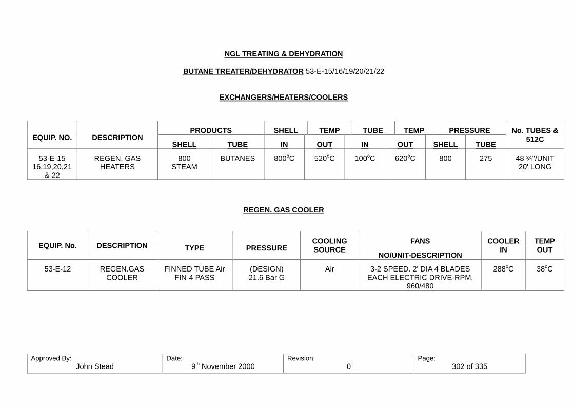
Approved By:John Stead
Date:9th November 2000
Revision:0
Page:302 of 335
NGL TREATING & DEHYDRATION
BUTANE TREATER/DEHYDRATOR 53-E-15/16/19/20/21/22
EXCHANGERS/HEATERS/COOLERS
PRODUCTS SHELL TEMP TUBE TEMP PRESSUREEQUIP. NO. DESCRIPTION
SHELL TUBE IN OUT IN OUT SHELL TUBE
No. TUBES &512C
53-E-1516,19,20,21
& 22
REGEN. GASHEATERS
800STEAM
BUTANES 800oC 520oC 100oC 620oC 800 275 48 ¾"/UNIT20' LONG
REGEN. GAS COOLER
FANSEQUIP. No. DESCRIPTION TYPE PRESSURE
COOLINGSOURCE
NO/UNIT-DESCRIPTION
COOLERIN
TEMPOUT
53-E-12 REGEN.GASCOOLER
FINNED TUBE AirFIN-4 PASS
(DESIGN)21.6 Bar G
Air 3-2 SPEED. 2' DIA 4 BLADESEACH ELECTRIC DRIVE-RPM,
960/480
288oC 38oC

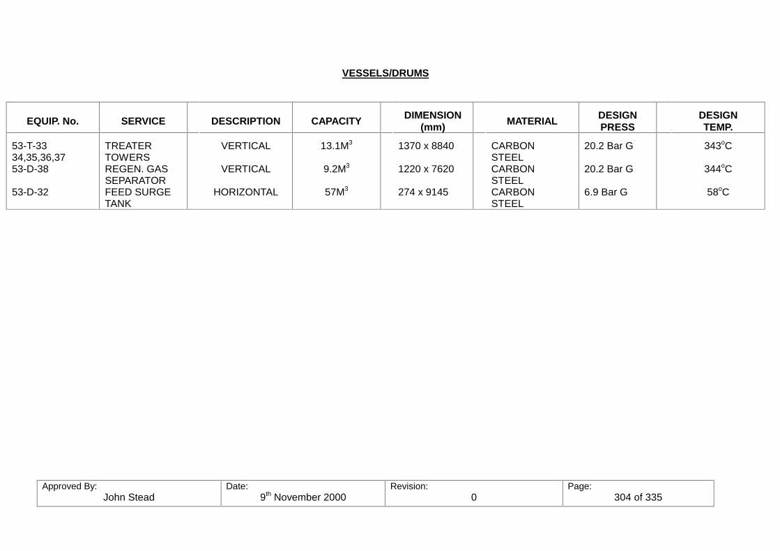
Approved By:John Stead
Date:9th November 2000
Revision:0
Page:304 of 335
VESSELS/DRUMS
EQUIP. No. SERVICE DESCRIPTION CAPACITY DIMENSION(mm) MATERIAL DESIGN
PRESSDESIGNTEMP.
53-T-3334,35,36,3753-D-38
53-D-32
TREATERTOWERSREGEN. GASSEPARATORFEED SURGETANK
VERTICAL
VERTICAL
HORIZONTAL
13.1M3
9.2M3
57M3
1370 x 8840
1220 x 7620
274 x 9145
CARBONSTEELCARBONSTEELCARBONSTEEL
20.2 Bar G
20.2 Bar G
6.9 Bar G
343oC
344oC
58oC
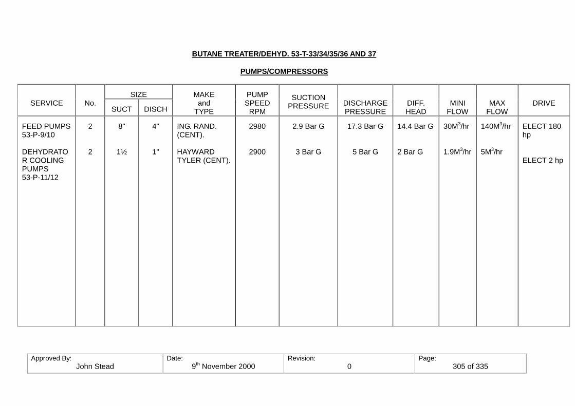
Approved By:John Stead
Date:9th November 2000
Revision:0
Page:305 of 335
BUTANE TREATER/DEHYD. 53-T-33/34/35/36 AND 37
PUMPS/COMPRESSORS
SIZESERVICE No.
SUCT DISCH
MAKEand
TYPE
PUMPSPEED
RPM
SUCTIONPRESSURE DISCHARGE
PRESSUREDIFF.HEAD
MINIFLOW
MAXFLOW
DRIVE
FEED PUMPS53-P-9/10
DEHYDRATOR COOLINGPUMPS53-P-11/12
2
2
8"
1½
4"
1"
ING. RAND.(CENT).
HAYWARDTYLER (CENT).
2980
2900
2.9 Bar G
3 Bar G
17.3 Bar G
5 Bar G
14.4 Bar G
2 Bar G
30M3/hr
1.9M3/hr
140M3/hr
5M3/hr
ELECT 180hp
ELECT 2 hp
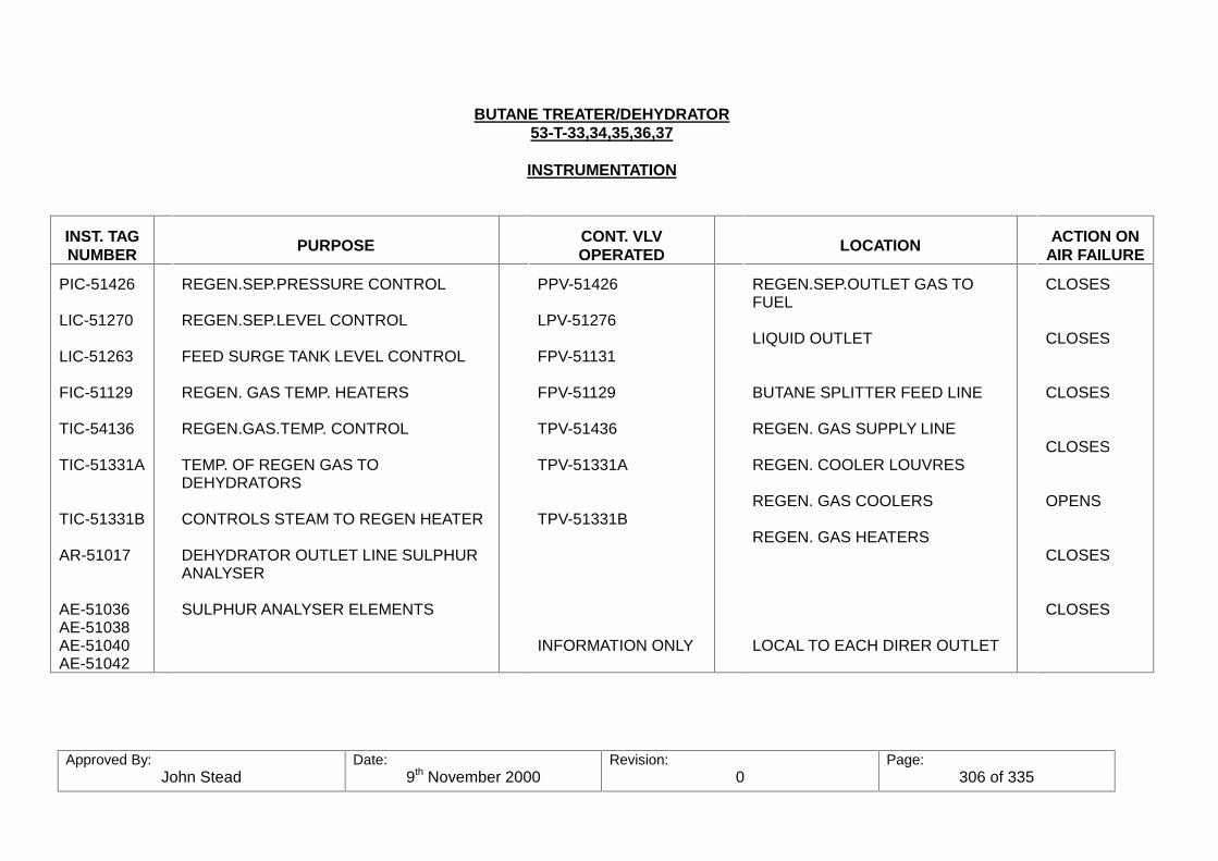
Approved By:John Stead
Date:9th November 2000
Revision:0
Page:306 of 335
BUTANE TREATER/DEHYDRATOR53-T-33,34,35,36,37
INSTRUMENTATION
INST. TAGNUMBER PURPOSE CONT. VLV
OPERATED LOCATION ACTION ONAIR FAILURE
PIC-51426
LIC-51270
LIC-51263
FIC-51129
TIC-54136
TIC-51331A
TIC-51331B
AR-51017
AE-51036AE-51038AE-51040AE-51042
REGEN.SEP.PRESSURE CONTROL
REGEN.SEP.LEVEL CONTROL
FEED SURGE TANK LEVEL CONTROL
REGEN. GAS TEMP. HEATERS
REGEN.GAS.TEMP. CONTROL
TEMP. OF REGEN GAS TODEHYDRATORS
CONTROLS STEAM TO REGEN HEATER
DEHYDRATOR OUTLET LINE SULPHURANALYSER
SULPHUR ANALYSER ELEMENTS
PPV-51426
LPV-51276
FPV-51131
FPV-51129
TPV-51436
TPV-51331A
TPV-51331B
INFORMATION ONLY
REGEN.SEP.OUTLET GAS TOFUEL
LIQUID OUTLET
BUTANE SPLITTER FEED LINE
REGEN. GAS SUPPLY LINE
REGEN. COOLER LOUVRES
REGEN. GAS COOLERS
REGEN. GAS HEATERS
LOCAL TO EACH DIRER OUTLET
CLOSES
CLOSES
CLOSES
CLOSES
OPENS
CLOSES
CLOSES
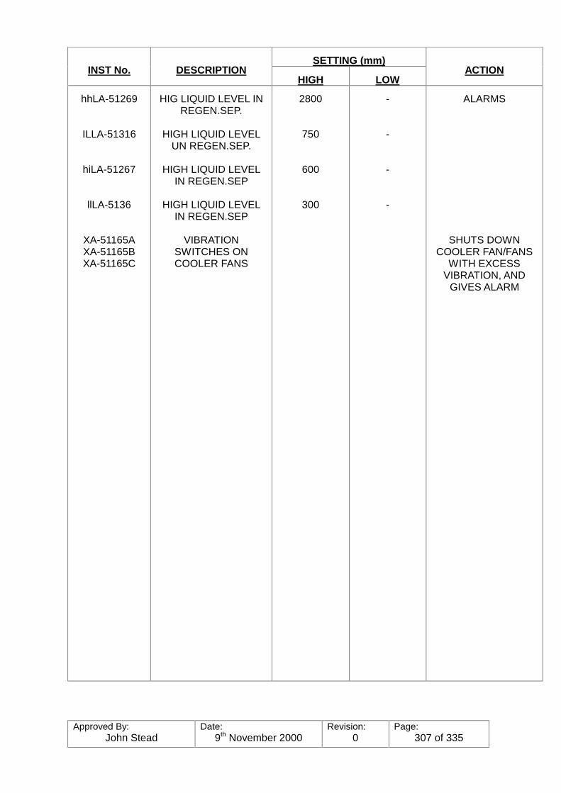
Approved By:John Stead
Date:9th November 2000
Revision:0
Page:307 of 335
SETTING (mm)INST No. DESCRIPTION
HIGH LOWACTION
hhLA-51269
ILLA-51316
hiLA-51267
llLA-5136
XA-51165AXA-51165BXA-51165C
HIG LIQUID LEVEL INREGEN.SEP.
HIGH LIQUID LEVELUN REGEN.SEP.
HIGH LIQUID LEVELIN REGEN.SEP
HIGH LIQUID LEVELIN REGEN.SEP
VIBRATIONSWITCHES ONCOOLER FANS
2800
750
600
300
-
-
-
-
ALARMS
SHUTS DOWNCOOLER FAN/FANS
WITH EXCESSVIBRATION, AND
GIVES ALARM

Approved By:John Stead
Date:9th November 2000
Revision:0
Page:308 of 335
NGL TREATING & DEHYDRATIONBUTANE TREATER/DEHYDRATOR-
53-T-33/34/35/36/37ALARMS & SHUTDOWN
NUMBER DESCRIPTION HIGH SET LOW SET ACTION
hLA-51308
lLA-51309
llLNS-51301
hiLA-51265
IFA-51138
hTA-51331
hhLA-51269
llLA-51207
hTA-51436
lTA-51436
hANS-51017
FEED TANK HIGHLEVEL
FEED TANK LOWLEVEL
FEED TANK LOWLEVEL
HIGH H2O LEVEL INWATER BOOT ONFEED TANK
LOW FLOW FROMDEC 3 BOTTOMS TOThe TREATER FEEDTANK
HIGH TEMPERATUREALARM-REGEN. GAS
REGEN. SEPARATORHIGH LIQUID LEVEL
REGEN. SEPARATORHIGH WATER LEVEL
HIGH REGEN.COOLER INLET
LOW REGEN.COOLER INLET TEMP.
HIGH SULPHUR
1830 mm
920 mm
7800 mm
600 mm
915 mm
460 mm
ALARM ONLY
ALARM ONLY
SHUTS DOWN CHARGE PUMP
TRIPS FEV-51138 AND OPENSCHARGE PUMP MINIMUMFLOW LINE VALVE, FPV-51138
ALARMS AT o
ALARM
ALARM
ALARM
ALARM
ALARM
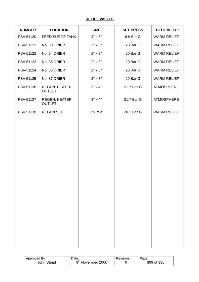
Approved By:John Stead
Date:9th November 2000
Revision:0
Page:309 of 335
RELIEF VALVES
NUMBER LOCATION SIZE SET PRESS BELIEVE TO:
PSV-51120
PSV-51121
PSV-51122
PSV-51123
PSV-51124
PSV-51125
PSV-51126
PSV-51127
PSV-51128
FEED SURGE TANK
No. 33 DRIER
No. 34 DRIER
No. 35 DRIER
No. 36 DRIER
No. 37 DRIER
REGEN. HEATEROUTLET
REGEN. HEATEROUTLET
REGEN.SEP.
4" x 6"
2" x 3"
2" x 3"
2" x 3"
2" x 3"
2" x 3"
3" x 4"
3" x 4"
1½" x 2"
6.9 Bar G
20 Bar G
20 Bar G
20 Bar G
20 Bar G
20 Bar G
21.7 Bar G
21.7 Bar G
20.2 Bar G
WARM RELIEF
WARM RELIEF
WARM RELIEF
WARM RELIEF
WARM RELIEF
WARM RELIEF
ATMOSPHERE
ATMOSPHERE
WARM RELIEF
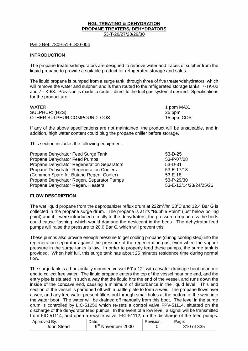
Approved By:John Stead
Date:9th November 2000
Revision:0
Page:310 of 335
NGL TREATING & DEHYDRATIONPROPANE TREATERS/ DEHYDRATORS
53-T-26/27/28/29/30
P&ID Ref: 7809-519-D00-004
INTRODUCTION
The propane treaters/dehydrators are designed to remove water and traces of sulpher from theliquid propane to provide a suitable product for refrigerated storage and sales.
The liquid propane is pumped from a surge tank, through three of five treater/dehydrators, whichwill remove the water and sulpher, and is then routed to the refrigerated storage tanks: 7-TK-02and 7-TK-63. Provision is made to route it direct to the fuel gas system if desired. Specificationsfor the product are:
WATER: 1 ppm MAX.SULPHUR: (H2S) 25 ppmOTHER SULPHUR COMPOUND: COS 15 ppm COS
If any of the above specifications are not maintained, the product will be unsaleable, and inaddition, high water content could plug the propane chiller before storage.
This section includes the following equipment:
Propane Dehydrator Feed Surge Tank 53-D-25Propane Dehydrator Feed Pumps 53-P-07/08Propane Dehydrator Regeneration Separators 53-D-31Propane Dehydrator Regeneration Coolers 53-E-17/18(Common Spare for Butane Regen. Cooler) 53-E-18Propane Dehydrator Regen. Separator Pumps 53-P-29/30Propane Dehydrator Regen. Heaters 53-E-13/14/23/24/25/26
FLOW DESCRIPTION
The wet liquid propane from the depropanizer reflux drum at 222m3/hr, 380C and 12.4 Bar G iscollected in the propane surge drum. The propane is at its "Bubble Point" (just below boilingpoint) and if it were introduced directly to the dehydrators, the pressure drop across the bedscould cause flashing, which would damage the desiccant in the beds. The dehydrator feedpumps will raise the pressure to 20.0 Bar G, which will prevent this.
These pumps also provide enough pressure to get cooling propane (during cooling step) into theregeneration separator against the pressure of the regeneration gas, even when the vapourpressure in the surge tanks is low. In order to properly feed these pumps, the surge tank isprovided. When half full, this surge tank has about 25 minutes residence time during normalflow.
The surge tank is a horizontally mounted vessel 60’ x 12’, with a water drainage boot near oneend to collect free water. The liquid propane enters the top of the vessel near one end, and theentry pipe is situated in such a way that the liquid hits the end of the vessel, and runs down theinside of the concave end, causing a minimum of disturbance in the liquid level. This endsection of the vessel is partioned off with a baffle plate to form a weir. The propane flows overa weir, and any free water present filters out through small holes at the bottom of the weir, intothe water boot. The water will be drained off manually from this boot. The level in the surgedrum is controlled by LIC-51250 which re-sets a control valve FPV-51114, situated on thedischarge of the dehydrator feed pumps. In the event of a low level, a signal will be transmittedfrom FIC-51114, and open a recycle valve, FIC-51112, on the discharge of the feed pumps.
Approved By:John Stead
Date:9th November 2000
Revision:0
Page:311 of 335
recycling propane back to the inlet of the surge drum. On a very low level the feed pumps willstop. The pressure in the surge drum is controlled, at approximately 11.0 Bar G. Thetemperature of the propane feed into the surge drum is set by the reflux condensers on theDepropanisers, 5-E-24/25. These condensers must be operated to give a feed temperature tothe dehydrators of the propane leaves the surge drum through a vortex breaker and flows to thesuction of the propane dehydrator feed pumps 53-P-07/08. One will be in operation and theother on stand-by.
Propane leaves the feed pumps at 20.0 Bar G and 38ºC, and design flow is 222 M3/hr to thedehydrator towers. Before entry to the towers, flow indicators are supplied on the inlet lines toeach tower for ensuring even distribution of flow through each tower on line (to be adjustedmanually).
There are five dehydrator/treater towers. Two will operate in parallel, drying the propane, whilethe other 3 are in different stages of regeneration.
The dehydrator towers are vertically mounted vessels 27' x 7'6" and filled with 1/16" LINDE 13xmolecular sieves. This bed is supported by a layer of 1/8" alumina balls, and that supported bya layer of 1/8 " alumina balls. As the propane flows through the desiccant bed, moisture andtraces of H2S will be absorbed in the desiccant. Normal flow is from BOTTOM TO TOP, whenon the drying step (in operation). The dry, treated propane leaves the top of the dehydrators,and flows to the propane storage tanks, 7-TK-01 & 63 via the propane product chiller, 7-E-19which drops the temperature of the propane product to -35.5ºC for storage. A continuous totalsulphur analyser AR 51016 has been installed on the common outlet product header, which willsound an alarm if the sulphur content of the propane becomes high (or if the analyser fails). Sine water is more strongly absorbed by the desiccant than sulphur compounds, the sulphur willbreak through long before the water. Consequently, only sulphur content is monitored todetermine the effectiveness of treating and dehydration.
REGENERATION
The various cycles for the dehydrators are controlled automatically by an automatic sequencecontroller which will start and stop pumps, establish and maintain flows, temperatures, andoperate the orbit valves to change over the dehydrators, etc, at the end of each different cycle.
Normal cycles are as follows:
ON STREAM (DRYING) - 24 hoursHEATING - 4 hoursCOOLING - 4 hoursSTAND-BY - 8 hours
During normal operation the timers will be set for three dehydrators "ON-LINE" in parallel, oneon "REGENERATION" (heating or cooling) and one on "STAND-BY" at any time. Because of the change in specification of the propane product the treaters are now changedover manually from the sequence controller sub panel. Instructions for the frequency of changeswill be issued in the daily operating instructions one is off-line for any reason, the timers can beset for shorter "drying" time or shorter "stand-by" time. High pressure fuel gas is used forregeneration of this system (heating step only), and also for the butane dehydrators. The fuelgas supply is not sufficient to enable both systems (propane and butane) to be on regeneration(heating) simultaneously. Interlocks have been fitted to the auto sequence timers to ensure thiswill never happen, therefore, this must be considered when times are being changed foralternative operation on the propane or butane systems.

Approved By:John Stead
Date:9th November 2000
Revision:0
Page:312 of 335
HEATING STEP
There are six regeneration heaters. They will operate in series of three when heating, i.e. 53-E-13/14/23 will be in service in series and heating, while 53-E-26/25/24 are on stand-by, or vice-versa..
Fuel gas is taken from the HP main header at 20.3 Bar G and 38ºC. The heaters will raise thetemperature to 316ºC with 55.2 Bar G steam. The regeneration gas flow is monitored andcontrolled by FIC-51120 at 8,000 NM3/hr, and is situated before the heaters.
The regeneration gas temperature is controlled by a split range controller, TIC-51312 "A" and"B". The "A" valve (3-way) is on the main regeneration gas flow situated at the inlet to theregeneration gas heaters. This will control the relevant amount of gas flowing through or by-passing the heater. When the by-pass port is closed (all flow through the heater), the "B" valve,which controls a flow of 55.2 Bar G steam from the heater to the 5.2 Bar G steam system willopen, allowing more stem to pass through the heater, therefore heating up the gas quicker. Once the temperature is raised to the set point (316º) the "B" valve will close and the "A" valvewill then control the temperature by allowing more or less through the by-pass.
The hot regeneration gas will flow to the TOP of the dehydrator, and join the normal outlet lineand flow DOWN through the bed, picking up the moisture and H2S from the desiccant.
The wet regeneration gas exits from the BOTTOM of the dehydrator, and flows to theregeneration coolers. The temperature of the gas is monitored at the common outlet line fromthe dehydrators by TR-51311. This temperature must be maintained above 258ºC in order toremove all traces of H2S from the desiccant, or the bed capacity for treating will be decreasedfor the next drying step.
There are two regeneration gas coolers, 53-E-17 and 18.53-E-17 will be in operation for thepropane system, and 53-E-18 is a common spare for both the propane and butane systems. Both are designed to run on a continuous basis while in operation. They have motor driven fans,forcing air through a radiator-type table bundle. Adjustable louvres are fitted on top which canreduce or increase the amount of air forced between the bundle tubes, allowing control over theoutlet temperature. Design temperature of the outlet is 38ºC. The adjustable louvres are autooperated by remote control with TIC-51329 "A" for 53-E-18 and "B" for 53-E-31. The controlsare situated in the NGL Control Room.
High and low temperature indicators are fitted in the outlet bin and will indicate in the NGLControl Room. Regeneration gas then flows to the regeneration separator.
The regeneration separator, 53-D-31 is a vertically mounted vessel, 25' x 6'7", with a demisterpad fitted near the top section. The gas enters the side and flows up through the pad and exitsfrom the top. Any liquid will adhere to the pad, and when the droplets become large enough, willdrop to the base of vessel. Level glasses and level indicators are fitted to the vessel, andhigh/low levels will alarm in the NGL Control Room. A separate level indicator controller, LIC-51257, is fitted, which will control the discharge flow from the pumps when the level is within itsrange. The level will also actuate "extra high" "extra low" switches to start and stop the separatorpumps 53-P-29/30. Propane liquid will be pumped with these pumps from the separator backto the inlet line of the dehydrator feed surge tank and join the normal flow again. One pump willbe in operation and one held as stand-by. Any water which may collect in the separator will bedrained off manually. The sour regeneration gas will exit from the top and return to the HP fuelgas header under pressure control with PIC-51398. Design conditions at this point are 8,000NM3/hr, 38�&�DW������%DU�*�COOLING STEP
After a bed has been fully heated, the regeneration gas flow is stopped. Liquid propane is takenfrom the discharge header of the dehydrator feed pumps (2" line), through FIC-51121, which will

Approved By:John Stead
Date:9th November 2000
Revision:0
Page:313 of 335
control the flow of cooling propane at 10M3/hr to the BOTTOM of the dehydrator. It will then jointhe normal inlet line and flow UP through the bed, cooling the desiccant. Propane vapours andliquid will exit from the top and will flow via the regeneration beds to the regeneration separator. All liquid propane is then pumped back to the feed surge tank via the separator pumps.
The cooling liquid propane flow rate is low enough that there is no danger of fluidizing a bedwhen the propane vaporises, as it will during the first part of the cooling step. If the flow rate istoo high, fluidizing could occur and would damage the desiccant due to the friction created.
During the cooling step, the temperature of the regeneration separator is also important. If thetemperature rises much above the design of 38ºC, an excessive amount of water could be re-cycled back to the feed surge tank. If it is too low, then the water could freeze and plug up theregeneration cooler. Therefore, the temperature must be checked regularly, particularly duringa cooling step. The TIC-51329 will indicate and alarm in the NGL Control Room. Initial setpoints for the alarms are recommended as follows:
HIGH - 41ºC (105ºF)LOW - 10ºC (50ºF)
ORIGINAL START UPregeneration gas coolers, Regeneration gas separators, and onPURGING OF Air:
Before any equipment can be started, wither from having been down for maintenance purposes,or for the original start-up, all air must be purged from the piping towers. Following is asuggested approach to that problem.
ORIGINAL START UP
1. Make a temporary tie-in off the nitrogen system into the Trtr. Feed Surge Tank.2. Have all trtr tower isolating valves blocked.3. Admit nitrogen to the surge tank, preferably through the 2" spool piece provided on the
bottom of the vessel.4. Displace the air in the tank by bleeding the vessel at all bleeder points, such as gauge
glasses, and also the 3" temporary tanker loading line. (Remove clapper in check valve,but make certain it is replaced afterwards).
5. After tests have been made, and the air content is down to an acceptable level, open upthe suction to the charge pump and displace air out the pump case bleeders. o thestand by pump likewise.
6. Next, open up the inlet to one tower, and bleed through the bleeder valves provided onthe relief valve setting. Do all towers in this manner until clear.
7. Now start concentrating on the regeneration gas lines by opening the regeneration gasinlet to the tower inlet lines one at a time, and bleeding off at the regeneration gas inletto the tower inlet lines one at a time, and bleeding off at the regeneration gas heaters. Clear on through the heaters one at a time by clearing through the bleeders on theregeneration gas temperature control valve.
8. After this line is clear, repeat the same exercise on the regeneration gas line from the topof the towers.
9. Block in the bleeders on the temperature control valve, and begin clearing the lines tothe through the pumps.
As stated above, this is just a suggested procedure, and other routes of nitrogen purge can befigured out. The main idea, however, is to make sure all piping and vessels have been purged. In some cases only parts of the treater may have been subjected to maintenance, such as a bedchange, which would require only the tower to be purged before start up. Specific instructionswill be issued in any case.

Approved By:John Stead
Date:9th November 2000
Revision:0
Page:314 of 335
ORIGINAL START UP
The following procedure assumes that the unit has been pressure tested with the necessarycorrections made, purged of air and all rotating equipment and instruments checked out. Alltowers are blocked in.
1. Fill towers 1 through 4 and the product line to storage with liquid propane. (Towers 26,27, 28 and 29). This can be done by opening the outlet and inlet valves on one bed ata time and checking at the one inch bleeder on the outlet of each tower for liquid. Thepropane product back pressure control valve located at the storage area should be setat 17.5 Bar G (225 psig) to insure that cooling propane can be delivered to theregeneration separator, 53-D-31.
2. After filling the vessels, close the inlet manually operated block valve on towers, 2, 3 and4.
3. Set the automatic valve sequencing controller to the start of the on stream step for Tower1. Start propane through Tower 1 at a flow rate of 29.4M3/hr. (At least). The flowthrough the individual towers must never be less than this rate.
4. Open the block valves on Tower 5 and start regeneration of Tower 5. Make sure theautomatic valve sequencer is on "Automatic".
5. Open outlet block valve on Tower 4 to place it on stand-by.
6. If after 8 hours the flow rate is below 58.8M3/hr., place Tower 3 on stream and close theinlet block valve on Tower 2.
7. If after 16 hours the flow rate is below 58.8M3/hr. place Tower 3 on stream and close theinlet block valve on Tower 2.
8. As soon as the flow rate is above 58.8M3/hr. two towers may be placed on stream inparallel. If the flow rate is above 88.2M3/hr. the three towers may be placed on stream.
For further details pertaining to the operation of the "Automatic Valve Sequencer", see write-upat the end of this section.
VALVE SEQUENCE CONTROLLER
PROPANE & BUTANE TREATERS
INTRODUCTION
The propane and butane treaters treat the top and bottom products of the depropaniserrespectively to remove any hydrogen sulphide and moisture from the streams.
Each treater comprises five vessels, 53-T-26/27/28/29 and 30 for the butane treater and 53-T-33/34/35/36 and 37 and for the butane treater. The vessels are referred to as ’bed 1’ ’bed 2’ ’bed3’ ’bed 4’ and ’bed 5’ for each treater in these instructions. (Refer to logic diagrams 5212 and5214 drawing number 7809.55J81-252 and 254).The sequence controller (UC51024) is designed to switch the beds of each treater automaticallythrough their draining and regeneration sequences. It is designed so that only one of the tenbeds can be regenerated at any one time. At any one time a bed can be:-
a) Drying with product inlet and outlet valves open and regeneration valves closed.b) Hot regenerating with product inlet and outlet valves closed, regeneration valves open
and hot gas passing through the heater down through the beds.

Approved By:John Stead
Date:9th November 2000
Revision:0
Page:315 of 335
c) Cooling with the product inlet and outlet valves closed, regeneration valves open withcooling liquid from the surge tank being passed through up the beds. The regenerationgas is shut off during cooling.
d) Idling with the product outlet valve open and the product inlet valve and regenerationvalves closed.
The bed may also be taken out of service with all the product and regeneration valves closed. The process requires that at any one time three beds on each treater are drying. The remainingbeds will be idling or regenerating. Only one bed may be regenerated at a time.
The regeneration of a bed will immediately follow its drying period. The operating sequence isdrying, hot regeneration, cooling, idling, drying, hot regeneration, cooling, idling, drying, hotregeneration, etc. (See logic diagrams 4213 and 5215 drawing numbers 7809-552J81-253 and255). Regeneration is achieved by passing heated regeneration time is fixed at 8 hours. (4hours hot regeneration and 4 hours cooling). The idling time is dependant on the drying timeand is adjusted automatically.
Provision is made for the removal of any bed from service operation on the other beds. In thissituation the remaining beds will continue with drying and regeneration periods unchanged butthe idling time will be reduced automatically. The cabinet housing the sequence controller islocated behind the control room panel (See Fig. Nos. 5-10 to 5-12). Two operator control units,one for each treater are mounted remotely in the control panel. (See Fig. Nos. 5-13 and 5-14).
In the automatic mode the controller maintains the correct sequence of operation by opening andclosing the product, regeneration and routing valves. The unit monitors the position of all valvesto ensure that each step of the sequence is done correctly. The status of each valve is displayedcontinuously on the graphic panel.
Any discrepancy between the actual valve position and that required for correct operation willsuspend the sequence and initiate an alarm. The state of each bed e.g. ’drying’ ’cooling’ etc. isalso indicated on the graphic panel. The sequence of operation under normal conditions isgiven later in this instruction.
The operator control units permit the operator to change the operation from automatic to manual,open and close any valve and to remove a train from service as follows:-
a) Any valve can be opened or closed by selecting the valve number on the thumbwheelswitch and pressing the ’open’ or ’close’ button, as appropriate. The valve position willbe indicated on the graphic panel.
b) The temperature control valves on the regeneration gas heater can be closed orcontrolled by the output of the temperature controller by pressing the appropriate button.
On start up it is necessary to preset the control valves on both treaters into one of fiveoperational patterns whilst the unit is in manual control prior to switching to automatic. Theseoperational patterns are shown on Fig. 5.1.
If it is required to remove a bed from service the right hand selector switch must indicate that bedand the ’out’ button are pressed. The effects of removing a bed from service are shown in Figs.5.3 to 5.7 inclusive, at various times within the sequence. When removed from service all valvesassociated with the out of service train will be closed. They can be operated locally withoutaffecting the auto-sequence. A bed can be returned to service by pressing the ’in’ button at anytime. The beds will automatically re-enter the sequence but only at their correctly appointedtime. (See Fig. 5.8). This is because the position of each bed within the sequence relative tothe other beds is always the same.
If a valve is operated locally whilst the sequence controller is in the ’Auto’ position the sequence
Approved By:John Stead
Date:9th November 2000
Revision:0
Page:316 of 335
will automatically suspend and an alarm will be initiated.
The sequence control unit is fed from three power sources:
a) 24v DC from the battery systemb) 110v DC from the battery systemc) 110v AC from the static inverter.
In the event of a failure of either or both of the DC supplies, the sequence controller will ceaseto function. As all the valves fail closed on power failure which for process considerations is notpracticable a separate solenoid valve has been fitted on to the air header supplying the valvesof each treater which in the event of poor failure will vent the air out of the header. This willensure that all valves remain in the position they enhoued prior to the poor supply failure. In theevent of failure of the 100 volts AC supply, which is only used to drive the timing mechanism,then the sequence will stop and hold the valves in the position they were at prior to the failure. On return to normal operation following failure of the DC power supplies it is necessary to followthe start up procedure. However, return of the AC supply will automatically restart the sequence. All the control valves except the temperature control valves are tight shut-off valves (orbit)powered by a double acting pneumatic diaphragm actuator. They are each fitted with a 4-portsolenoid valve, open and closed limit switches, restrictor, lock-up valve, lever operator pneumaticvalve and handwheel. Before placing the system in automatic operation it is necessary toensure that all handwheels are in neutral and that the lever operated valve s are in the normalposition.
The temperature control system on the regeneration gas heater has two control valves. Onlythe steam valve is operated by the sequence controller via a solenoid valve. A 3-way controlvalve is controlled by the output of the gas temperature controller during hot regeneration andwill open when the gas temperature required cannot be achieved by the usual steam supply.
The operation of the sequence controller is described in detail in this section. Reference shouldalso be made to the associated circuit diagrams at the back of the section.PROPANE TREATER
NORMAL OPERATING SEQUENCE
1. Time 0 Hrs. (&40 Hrs) Open XPV.51111 Liquid Inlet 53-T-26
2. Time 0 Hrs. (&40 Hrs) Close XPV.51131 Cooling Liquid
3. Step 1 Complete and Close XPV 51119 Liquid Inlet 53-T-28 Step 45 Complete Close XPV 51122 Liquid Outlet 53-T-28
4. Step 2 Complete Close XPV 51116 Regen. Outlet 53-T-27Close XPV 51117 Regen. Inlet 53-T-27
5. Step 4 Complete Open XPV 51118 Liquid Outlet 53-T-27
6. Step 4 Complete Open XPV 51132 Gas Routing ValveClose XPV 51133 Liquid Routing Valve
7. Step 6 Complete Open XPV 51120 Regen. Outlet 52-T-28 Step 3 Complete Open XPV 51135 Regen. Gas to Heater
TPV 51312B to Controller Steam from Heaters
8. Time 4 Hrs. Close XPV 51135 Regen. Gas to HeatersClose TPV 51312B Steam from Heaters

Approved By:John Stead
Date:9th November 2000
Revision:0
Page:317 of 335
9. Step 8 Complete Close XPV 51132 Gas Routing ValveOpen XPV 51133 Liquid Routing Valve
10. Step 9 Complete Open XPV 51131 Cooling Liquid
11. Time 8 Hrs Open XPV 51115 Liquid Inlet 53-T-27
12. Time 8 Hrs. Close XPV 51131 Cooling Liquid
13. Step 11 Complete and Close XPV 51123 Liquid Inlet 53-T-29 Step 5 Complete Close XPV 51126 Liquid Outlet 53-T-29
14. Step 12 Complete Close XPV 51120 Regen. Outlet 53-T-28Close XPV 51121 Regen. Inlet 53-T-28
15. Step 14 Complete Open XPV 51122 Liquid Outlet 53-T-28
16. Step 14 Complete Open XPV 51132 Gas Routing ValveClose XPV 51133 Liquid Routing Valve
17. Step 16 Complete and Open XPV 51124 Regen. Outlet 53-T-29 Step 13 Complete Open XPV 51125 Regen. Inlet 53-T-29
Open XPV 51135 Regen. Gas to HeatersTPV 51312B toController Steam from Heaters
18. Time 12 Hrs. Close XPV 51135 Regen. Gas to HeatersClose TPV 51312B Steam from Heaters
19. Step 18 Complete Close XPV 51132 Gas Routing ValveOpen XPV 51133 Liquid Routing Valve
20. Step 19 Complete Open XPV 51131 Cooling Liquid
21. Time 16 Hrs. Open XPV 51119 Liquid Inlet. 53-T-28
22. Time 16 Hrs. Close XPV 51131 Cooling Liquid
23. Step 21 Complete and Close XPV 51127 Liquid Inlet 53-T-30 Step 15 Complete Close XPV 51130 Liquid Outlet 53-T-30
24. Step 22 Complete Close XPV 51124 Regen. Outlet 53-T-29Close XPV 51125 Regen. Inlet 53-T-29
25. Step 24 Complete Open XPV 51126 Liquid Outlet 53-T-29
26. Step 24 Complete Open XPV 51132 Gas Routing ValveClose XPV 51133 Liquid Routing Valve
27. Step 26 Complete and Open XPV 51128 Regen. Outlet 53-T-30 Step 23 Complete Open XPV 51135 Regen. Inlet 53-T-30
Open XPV 51135 Regen. Gas to HeatersTPV 51312B to Controller Steam from Heaters
28. Time 20 Hrs. Close XPV 51135 Regen. Gas to HeatersClose TPV 51312B Steam from Heaters
29. Step 28 Complete Close XPV 51132 Gas Routing Valve

Approved By:John Stead
Date:9th November 2000
Revision:0
Page:318 of 335
Open XPV 51133 Liquid Routing Valve
30. Step 29 Complete Open XPV 51131 Cooling Liquid
31. Time 24 Hrs. Open XPV 51123 Liquid Inlet 53-T-29
32. Time 24 Hrs
33. Step 31 Complete and Close XPV 51111 Liquid Inlet 53-T-26 Step 25 Complete Close XPV 51114 Liquid Outlet 53-T-26
34. Step 32 Complete Close XPV 51128 Regen. Outlet 53-T-30
Close XPV 51129 Regen. Inlet 53-T-30
35. Step 34 Complete Open XPV 51130 Liquid Outlet 53-T-30
36. Step 34 Complete Open XPV 51132 Gas Routing ValveClose XPV 51133 Liquid Routing Valve
37. Step 36 Complete and Open XPV 51112 Regen. Outlet 53-T-26 Step 33 Complete Open XPV 51113 Regen. Inlet 53-T-26
Open XPV 51135 Regen. Gas to HeatersTPV 51312B to Controller Steam from Heaters
38. Time 28 Hours Close XPV 51135 Regen. gas to HeatersClose TPV 51312B Steam from Heaters
39. Step 38 Complete Close XPV 51132 Gas Routing ValveOpen XPV 51133 Liquid Routing Valve
40. Step 39 Complete Open XPV 51131 Cooling Liquid
41. Time 32 Hrs. Open XPV 51127 Liquid Inlet 53-T-30
42. Time 32 Hrs Close XPV 51131 Cooling Liquid
43. Step 41 Complete and Close XPV 51115 Liquid Inlet 53-T-27 Step 35 Complete Close XPV 51118 Liquid Outlet 53-T-27
44. Step 42 Complete Close XPV 51112 Regen. Outlet 53-T-26Close XPV 51113 Regen. Inlet 53-T-26
45. Step 44 Complete Open XPV 51114 Liquid Outlet 53-T-26
46. Step 44 Complete Open XPV 51132 Gas Routing ValveClose XPV 51133 Liquid Routing Valve
47. Step 46 Complete and Open XPV 51116 Regen. Outlet 53-T-27 Step 43 Complete Open XPV 51117 Regen. Inlet 53-T-27
Open XPV 51135 Regen. Gas to HeatersTPV 51312B to Controller Steam from Heaters
48. Time 36 Hrs. Close XPV 51135 Regen. Gas to HeatersClose TPV 51312B Steam from Heaters
Approved By:John Stead
Date:9th November 2000
Revision:0
Page:319 of 335
49. Step 48 Complete Close XPV 51132 Gas Routing ValveOpen XPV 51133 Liquid Routing Valve
50. Step 49 Complete Open XPV 51131 Cooling Liquid
51. Time 40 Hrs. (&0 Hrs.) CYCLE REPEATS FROM STEP 1.
BUTANE TREATER
NORMAL OPERATING SEQUENCE
1. Time 0 Hrs. Close XPV 51162 Regen. Gas to Heaters (& 0 Hrs.) Close TPV 51331B Steam from Heaters
2. Step 1 Complete Close XPV 51158 Gas Routing ValveOpen XPV 51159 Liquid Routing Valve
3. Step 2 Complete Open XPV 51160 Cooling Liquid
4. Time 4 Hrs. Open XPV 51137 Liquid Inlet 53-T-33
5. Time 4 Hrs. Close XPV 51160 Cooling Liquid
6. Step 4 Complete Close XPV 51145 Liquid Inlet 53-T-35 & Step 48 Complete Close XPV 51148 Liquid Outlet 53-T-35
7. Step 5 Complete Close XPV 51142 Regen. Outlet 53-T-34Close XPV 51143 Regen. Inlet 53-T-34
8. Step 7 Complete Open XPV 51144 Liquid Outlet 53-T-34
9. Step 7 Complete Open XPV 51158 Gas Routing ValveClose XPV 51159 Liquid Routing Valve
10. Step 9 Complete Open XPV 51146 Regen. Outlet 53-T-35 & Step 6 Complete Open XPV 51162 Regen. Inlet 53-T-35
Open XPV 51162 Regen. Gas to HeatersTPV 51331B to Controller Steam from Heaters
11. Time 8 Hrs. Close XPV 51162 Regen. Gas to HeatersClose TPV 51331B Steam from Heaters
12. Step 11 Complete Close XPV 51158 Gas Routing ValveOpen XPV 51159 Liquid Routing Valve
13. Step 12 Complete Open XPV 51160 Cooling Liquid
14. Time 12 Hrs. Open XPV 51141 Liquid Inlet 53-T-34
15. Time 12 Hrs. Close XPV 51160 Cooling Liquid
16. Step 14 Complete Close XPV 51149 Liquid Inlet 53-T-36 & Step 8 Complete Close XPV 51152 Liquid Outlet 53-T-36
17. Step 15 Complete Close XPV 51146 Regen. Outlet 53-T-35

Approved By:John Stead
Date:9th November 2000
Revision:0
Page:320 of 335
Close XPV 51147 Regen. Inlet 53-T-35
18. Step 17 Complete Open XPV 51148 Liquid Outlet 53-T-35
19. Step 17 Complete Open XPV 51158 Gas Routing ValveClose XPV 51159 Liquid Routing Valve
20. Step 19 COMPLETE Open XPV 51150 Regen. Outlet 53-T-36 & Step 16 Complete Open XPV 51151 Regen. Inlet 53-T-36
Open XPV 51162 Regen. Gas to HeatersTPV 51331B to Controller Steam from Heaters
21. Time 16 Hrs. Close XPV 51162 Regen. Gas to HeatersClose TPV 51331B Steam from Heaters
22. Step 21 Complete Close XPV 51158 Gas Routing ValveOpen XPV 51159 Liquid Routing Valve
23. Step 22 Complete Open XPV 51160 Cooling Liquid
24. Time 20 Hrs. Open XPV 51145 Liquid Inlet 53-T-35
25. Time 20 Hrs. Close XPV 51160 Cooling Liquid
26. Step 24 Complete Close XPV 51153 Liquid Inlet 53-T-37 & Step 18 Complete Close XPV 51156 Liquid Outlet 53-T-37
27. Step 25 Complete Close XPV 51150 Regen. Outlet 53-T-36Close XPV 51151 Regen. Inlet 53-T-36
28. Step 27 Complete Open XPV 51152 Liquid Outlet 53-T-36
29. Step 27 Complete Open XPV 51158 Gas Routing ValveClose XPV 51159 Liquid Routing valve
30. Step 29 Complete Open XPV 51154 Regen. Outlet 53-T-37 & Step 26 Complete Open XPV 51155 Regen. Inlet 53-T-37
Open XPV 51162 Regen. Gas to HeatersTPV 51331B to Controller Steam from Heaters
31. Time 24 Hrs. Close XPV 51162 Regen. Gas to HeatersClose TPV 51331B Steam from Haters
32. Step 31 Complete Close XPV 51158 Gas Routing ValveOpen XPV 51159 Liquid Routing Valve
33. Step 32 Complete Open XPV 51160 Cooling Liquid
34. Time 28 Hrs. Open XPV 51149 Liquid Inlet 53-T-36
35. Time 28 Hrs. Close XPV 51160 Cooling Liquid
36. Step 34 Complete Close XPV 51137 Liquid Inlet 53-T-33 & Step 28 Complete Close XPV 51140 Liquid Outlet 53-T-33
37. Step 35 Complete Close XPV 51154 Regen. Outlet 53-T-37Close XPV 51155 Regen. Inlet 53-T-37

Approved By:John Stead
Date:9th November 2000
Revision:0
Page:321 of 335
38. Step 37 Complete Open XPV 51156 Liquid Outlet 53-T-37
39. Step 37 Complete Open XPV 51158 Gas Routing ValveClose XPV 51159 Liquid Routing Valve
40. Step 39 Complete Open XPV 51138 Regen. Outlet 53-T-33 & Step 36 Complete Open XPV 51139 Regen. Inlet 53-T-33
Open XPV 51162 Regen. Gas to HeatersTPV 51331B to Controller Steam from Heaters
41. Time 32 Hrs. Close XPV 51162 Regen. Gas to HeatersClose TPV 51131B Steam from Heaters
42. Step 41 Complete Close XPV 51158 Gas Routing ValveOpen XPV 51159 Liquid Routing Valve
43. Step 42 Complete Open XPV 51160 Cooling Liquid
44. Time 36 Hrs. Open XPV 51153 Liquid Inlet 53-T-37
45. Time 36 Hrs. Close XPV 51160 Cooling Liquid
46. Step 44 Complete Close XPV 51141 Liquid Inlet 53-T-34 & Step 38 Complete Close XPV 51144 Liquid Outlet 53-T-34
47. Step 45 Complete Close XPV 51138 Regen. Outlet 53-T-33Close XPV 51139 Regen. Inlet 53-T-33
48. Step 47 Complete Open XPV 51140 Liquid Outlet 53-T-33
49. Step 47 Complete Open XPV 51158 Gas Routing ValveClose XPV 51159 Liquid Routing Valve
50. Step 49 Complete Open XPV 51142 Regen. Outlet 53-T-34 & Step 46 Complete Open XPV 51143 Regen. Inlet 53-T-34
Open XPV 51162 Regen. Gas to HeatersTPV 51331B to Controller Steam from Heaters
51. TIME 40 Hrs. (& 0 Hrs.) CYCLE REPEATS FROM STEP 1

Approved By:John Stead
Date:9th November 2000
Revision:0
Page:322 of 335
5. SEQUENCE CONTROLLER FOR PROPANE AND BUTANE TREATERS-CABINET UC51024
5.1 General Description
The sequence controller consists of solid state circuit modules mounted on standardcards in racks together with relays and other electromechanical devices, mounted withina two-bay steel enclosure UC 51024, and two separate control sub-panels.
The racks are mounted on swing frames which allows access to the rear of the cardsockets and to the rear of the cabinet.
Connection to plant equipment is via screw-clamp terminals situated within the rear ofthe enclosure, entry to which is by top and bottom entry gland plates.
The logic circuits are connected to the screw-clamp terminals through plugs and socketsadjacent to the terminals. This enables the logic to be disconnected from the plantswitches and solenoids, and connected to the simulator (see Part IV) for testing andfault-finding.
The propane and butane circuits may be electrically isolated by means of push-buttonson the swing frame.
The logic circuits have been broken down into blocks to facilitate description, and thepropane circuits operate independently of the butane circuits with the exception of thetiming logic which is common. The sequences for the two treaters are the same, but thebutane sequence ’lags’ the propane sequence by four hours.
This means that only one bed is either on cold regeneration or hot regeneration at anytime.
5.2 Operational Description - Cabinet UC51024
5.2.1 Start Up and Normal Operation
Before applying the supply to the circuits of wither treater the AUTO/MANUALswitches on the sub-panels should be set to MANUAL.
The START push-button for propane may bow be operated, but at this point intime all plant solenoids will remain de-energised. It is now possible to operate thepropane plant manually from the propane sub-panel.
Similarly the START push-button for butane may also be operated, to allow thebutane plant to be controlled manually from the butane sub-panel.
Valves, TPV 51312B (propane) and TPV 51331B (butane) may be opened orclosed by operating the appropriate push-buttons on the sub-panels.
Valves XPV 51111 to XPV 51133 and XPV 51135 may be operated by selectingthe last two digits of the valve number on the propane sub-panel thumbwheelswitches and then operating the OPEN or CLOSE push-button to the left of thethumbwheel switches. The valve selected will remain in the state chosen eventhough other valves may be selected.
Similarly, valves XPV 51137 to XPV 51156, XPV 51158 to XPV 51160 and XPV51162 may be operated from the butane sub-panel.

Approved By:John Stead
Date:9th November 2000
Revision:0
Page:323 of 335
If it is required to operate the plant in AUTO, it is first necessary to set all propanevalves manually to one of five start points. These five points are shown in Fig.5.1.
The rotary switch on the propane sub-panel headed BED TO START ONREGENERATION AT START OF AUTO SEQUENCE should be set to thecorresponding position. The propane AUTO push-button may now be operatedand the propane plant will continue to operate automatically according to thesequence shown in Fig, 5.1, and the manual controls will be rendered ineffective.
A similar procedure should be carried out for butane using the butane sub-panelcontrols. However, since the butane sequence ’lags’ the propane sequence byfour hours of the propane sequence. As the time lag is set automatically thebutane AUTO push-button may be operated at any time within the first four hoursof the propane sequence.
Fig 5.1 shows a sequence where propane entered service at start point 4 andbutane at start point 2. Any start point between 1 and 5 in each case ispermissible.
In Fig. 5.1 the beds are shown as drying, idling or regenerating.
During drying, the LIQUID INLET and LIQUID OUTLET valves only are open.
During idling the LIQUID OUTLET valve only is open.
During regeneration the REGEN OUTLET and REGEN INLET valves only areopen.
For the first four hours of regenerating the steam valve is open.
The valves are designated as follows (X)V preceeds all valve numbers).
PROPANE
DUTY COLUMN COLUMN COLUMN COLUMN COLUMN
53-T-26 53-T-27 53-T-28 53-T-29 53-T-30
Liquid Inlet 51111 51115 51119 51123 51127Regen Outlet 51112 51116 51120 51124 51128Regen Inlet 51113 51117 51121 51125 51129Liquid Outlet 51114 51118 51122 51126 51130
Cooling Liquid - XPV 51131Gas Routing Valve - XPV 51132Liquid Routing Valve - XPV 51135Regen Gas - XPV51312B
Approved By:John Stead
Date:9th November 2000
Revision:0
Page:324 of 335
DUTY COLUMN COLUMN COLUMN COLUMN COLUMN
53-T-33 53-T-34 53-T-35 53-T-36 53-T-37
Liquid Inlet 51137 51141 51145 51149 51153Regen Outlet 51138 51142 51146 51150 51154Regen Inlet 51139 51143 51147 51151 51155Liquid Outlet 51140 51144 51148 51152 51156
Cooling Liquid - XPV 51160Gas Routing Valve - XPV 51158Liquid Routing Valve - XPV 51159Regen Gas - XPV 51162Steam - TPV 51131B
The GAS ROUTING valve and REGEN. GAS valve are open for the first fourhours of regeneration, and the COOLING LIQUID valve and LIQUID ROUTINGvalve are open for the remainder of the regeneration period.
Referring to Fig. 5.1, it may be noted that a sequence can be broken down intoequal sections - in this case of 8 hours each.
This the during period occupies 3 sections and regeneration and idle one sectioneach.
During commissioning or other shut-down times the length of the sections maybe set between 8 hours and 16 hours in 20 minute increments by setting the totaldrying time, which is effected bu operation of two thumbwheel switches within themain enclosure (See Technical Description).
The thumbwheel should only be varied between 24 (which gives 24 hours dryingtime and 8 hour sections) and 48 (which gives 48 hours drying time and 16 hoursections).
Fig 5.2 shows a sequence with 12 hours sections - that is 36 hours drying time. It will be noted that drying still occupies 3 sections but regeneration time remainsconstant at 8 hours as in Fig. 5.1. The remainder of the section following dryingis then taken up as idling. In this case the propane and butane sequences haveboth entered AUTO operation at start point 1.
5.2.2 Taking a Bed out of Service
Once ion service the propane and butane sequences operate independentlyalthough the length of each section of operation is not independent. This thefollowing applies equally to the propane or butane sequences.
During normal AUTO operation on bed only may be out of service at any onetime. Interlocking ensures that another bed may not be taken out when the bedout push-button has been operated.
To take a bed out of service the sub-panel rotary switch designated BED TO BETAKEN OUT OF SERVICE is set at the appropriate position. The push-buttonto the right of the rotary switch is then operated.
The sequence immediately following the action of taking a bed out will dependon the point at which the bed is taken out. Figs. 5-3 to 5-7 show the resultingsequences when Bed 3 is taken out during each of its section of operation. For the
Approved By:John Stead
Date:9th November 2000
Revision:0
Page:325 of 335
purposes of discussion the section immediately following drying will be referredto as regeneration even though the first 8 hours only are taken up theregeneration.
The drying time is 30 hours in Figs. 5-3 to 5-7.
5.2.3 Returning a Bed to Service
This may be accomplished by setting the rotary switch of para. 5.2.2 to theappropriate position and operating the push-button.
The push-button may be operated at any time, however the bed will not bereturned to service until the point is reached in the sequence at which it would beentering its regeneration stage. This is shown more clearly in Fig. 5-8.
Instrument Air Failure: All switching valves controlled by the automatic valvesequencer control will stay in the position they were in at the time of the failure,but the Regeneration Separator Pump must be shut down because its outercontrol will shut off. Shut down the Feed Pumps, 519-670-07 or 08 to stop theminimum flow back to the feed tank. All control valves will close, therebystopping the propane, and regeneration flow to and from the Trtr. The bleedsteam from the heaters will also close.
Electrical Failure: All motors will stop. This will get the Regeneration Gas CoolerFans, Feed Pumps and Separator Pumps.
All switching valves controlled by the automatic valve sequencer control willremain in the position they were in at the time the failure occurred.
Block in the steam leaving the Regeneration Gas Heater, otherwise there will bea continuous loss of 55 bar g steam into the 17.2 bar g steam system.
Sulpher Analyser: A continuous total sulphur analyser has been installed (AR-51016) on the treater outlet which will sound an alarm, (AR-51016), if the sulphurcontent of the propane gets too high. This alarm will sound long before any watergets through.

Approved By:John Stead
Date:9th November 2000
Revision:0
Page:326 of 335
Approved By:John Stead
Date:9th November 2000
Revision:0
Page:327 of 335
NGL TREATING & DEHYDRATIONPROPANE DEHYDRATOR/TREATERS
PUMPS/COMPRESSORS
EQUIP. NO. DESCRIPTION TYPE DRIVE CAPACITY DISCH.PRESS.SUB-STATION

Approved By:John Stead
Date:9th November 2000
Revision:0
Page:328 of 335

Approved By:John Stead
Date:9th November 2000
Revision:0
Page:329 of 335

Approved By:John Stead
Date:9th November 2000
Revision:0
Page:330 of 335

Approved By:John Stead
Date:9th November 2000
Revision:0
Page:331 of 335

Approved By:John Stead
Date:9th November 2000
Revision:0
Page:332 of 335
Approved By:John Stead
Date:9th November 2000
Revision:0
Page:333 of 335
DEOILER FRACTIONATOR
5-T-08
HISTORY
Under the original design concepts this column was to be used as an iso-butane de-propanizer,but shortly after the initial plant start up it became apparent that the column duty changed. It ishowever worth pointing out it would be a fairly easy job to return the column duty back to itsoriginal state if it were so desired.
The following write up is therefore for the column as we now operated i.e. a deoiler.
1. Purpose and Services:
The purpose of the deoiler is to remove the heavier C5 (pentane) fraction from the normalbutane product ex the C4 splitter column bottoms.
The system includes the fractionating tower, overhead condensing system (air cooledcondensing coils), accumulator and pumps.
a. Feed - the normal feed to the deoiler is the pentane drag stream from the bottomof the butane splitter containing iso and normal pentane and normal butane. Thefeed enters the column at a temperature of60-65ºC at on of two inlet points either tray 28 or tray 34.
b. Overhead Product - the overhead product is normal butane which is to be addedto the main normal butane product from tray 5 (sidedraw) of the Butane Splitter,and the combined streams are then sent to storage.
c. Bottom Product - the bottom product is the iso and normal pentane fraction whichties in to the combined stabilised crude rubdown and then to Greatham storage.
2. Process Equipment and Flow Arrangement
a. The feed is pressured from the base of the butane splitter via a 4" line througha fin fan cooler 5-E-18 (NB this cooler now has the fans shut-down as it wasoriginally a rundown cooler when the column was run as an iso-butanedepropaniser. The feed flow is controlled by FIC 51141 and from here it passesto the column and enters via feed points on the 28th or 34th trays.
The reboiler is heated with a steam supply at 3.4 bar g (50 psig) and 148ºC(298ºF). The steam pressure reduces to about 2.1 bar g (30 psig) across thesteam control valve PPV-51139 on its way to the heating element.
Control System
a. Feed to the column is on flow control, FPV-51141
Steam to the reboiler is on flow control, FPV-51199 reset by Distillation Column Control,or tray temperature control TIC 51368 from either the 5th or 45th tray level. Condensateis on condensate accumulator liquid level control resetting control valve PLV-51290 inthe discharge of the condensate pump. Minimum flow protection is provided for thepumps.
Approved By:John Stead
Date:9th November 2000
Revision:0
Page:334 of 335
The Bottom Product rate is on flow control FPV-51136. Bottom product temperature hasno control other than fan adjustments on the Bottoms cooler, 5-E-44.
Column Pressure is on back pressure control PPV-51479 reset by PIC 51479 whichreceives its signal from pressure transmitter PNT-51479 located in the overhead vapourline ahead of the back pressure control valve. The column is controlled by top pressure.
Reflux Temperature is not directly controlled, but indirectly by louvre adjustments onhand control HIC-51044, and by utilising the two speed fans provided.
Accumulator Pressure is controlled by adjusting PIC-51482, which controls the three wayvalve PPV-51482 located in the overhead vapour line ahead of the air fin condenser. This allows a controlled amount of hot vapours to by-pass the overhead condensers,505-410-19 and go straight to the accumulator. A pressure point on the accumulatortransmits the accumulator pressure to the PIC-51482.
External Refuls is controlled by FPV 51140.
Accumulator Level is controlled by drum level LIC 51297 resetting. FPV 51142A normalbutane product.
In the event that the column has to be taken off stream, the feed, overhead product andbottom product may be switched to the relief system by full-opening ball valves. Theseare:
Feed - HPV 51043 to warm reliefOHP - HPV 51071 to cold reliefBott. Prod. - HPV 51040 to warm relief (suction of drag pump 5-P-26)
7. ALARMS AND SAFETY FEATURES
The column over-pressure devices are designed to have four stages of protection withincreasing pressure: (1) ALARM, (2) steam shut-off, (3) Vent to the enclosed reliefsystem, and (4) last resort, vent to the atmosphere from the top of the column. Theaccumulator also has a safety valve that will relieve to the relief system. A list of alarmsand safety valves follow:
1. High Press. alarm hhPa-514772. Steam shut-off hhPNS-514773. Col. vent to warm relief system PSV-51090 set at 17.4 bar g4. Accum. vent to warm relief system PSV 51093 set at 18 bar g5. Col. vent to atmosphere PSV 51091 set at 21.4 bar g
Approved By:John Stead
Date:9th November 2000
Revision:0
Page:335 of 335
INSTRUMENTSDEOILER 5-T-08
INST. NO. DESCRIPTION SIGNAL ACTION AIR FAILURE RESETS
LIC-51293
FIC-51141
FPV-51141
FIC-51139
FPV-51139
PIC-51479
PPV-51479
PIC-51482
PPV-51482
HIC-51044
HPV-51044