nim-hv-psu presentation - uhm physics and astronomyidlab/taskandschedule/... · nim-hv-psu...
TRANSCRIPT

Vihtori Virta
12/16/2014
NIM-HV-PSU PRESENTATION

Content
12/16/2014 2
Display Board
High Voltage Board
3D Model
Mechanical Design
What was learnt during the project
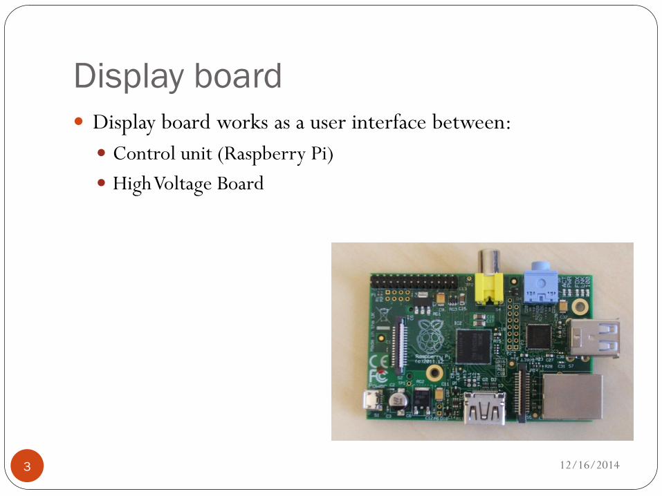
Display board
12/16/2014 3
Display board works as a user interface between:
Control unit (Raspberry Pi)
High Voltage Board

Regulator and Fuse
12/16/2014 4
Fuse / Polyswitch
Regulator
Power dissipation
(Vin-Vout)*Iout = (6V-5V)*1,5A = 1.5W
Max Voltage Max Current Current-Hold Current-Trip R Min/Max Time to Trip
13,2 V 100A 750mA (Max) 1,5A 0,110-0,450Ω 0,2s
Dropout Voltage Output Current Quiescent current
0,4 V at Iout = 1,5A 3A 50 µA
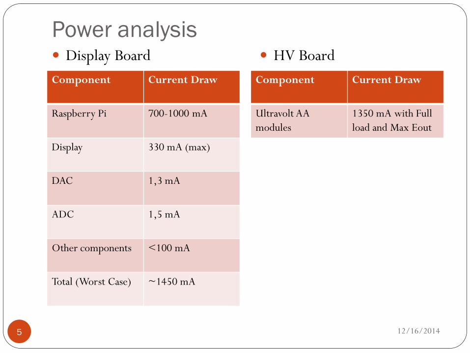
Power analysis
12/16/2014 5
Component Current Draw
Raspberry Pi 700-1000 mA
Display 330 mA (max)
DAC 1,3 mA
ADC 1,5 mA
Other components <100 mA
Total (Worst Case) ~1450 mA
Component Current Draw
Ultravolt AA
modules
1350 mA with Full
load and Max Eout
Display Board HV Board

Switch and rotary encoder functionality
12/16/2014 6
“Top Switch”
Power on
LED indicates that PSU is on
Other switches
HV channels on
LED indicates that the channel
is on
Rotary encoder
2-bit quadrature code

RPI Connection
12/16/2014 7
GPIO voltage levels are 3.3 V and are not 5 V tolerant.
No over-voltage protection on the board

ADC and DAC Connection
12/16/2014 8
DAC
Reset delay: 300 ms
To make sure that RPI
wakes up first
ADC
Reference pin must have
1µF and 0.1µF Capacitors

Display connection
12/16/2014 9

Delay circuit for HV EN/DIS pin
12/16/2014 10
500ms delay circuit to make sure that the HV modules wakes
up at the disabled state
Simulations are done with the FET with different threshold
voltage and thus is slightly incorrect

Simulation result
12/16/2014 11

Connector comparison
12/16/2014 12
Display Board HV Board
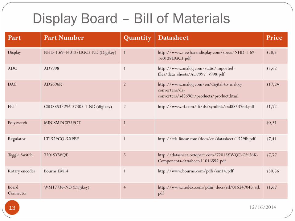
Display Board – Bill of Materials
12/16/2014 13
Part Part Number Quantity Datasheet Price
Display NHD-1.69-160128UGC3-ND (Digikey) 1 http://www.newhavendisplay.com/specs/NHD-1.69-
160128UGC3.pdf
$28,5
ADC AD7998 1 http://www.analog.com/static/imported-
files/data_sheets/AD7997_7998.pdf
$8,62
DAC AD5696R 2 http://www.analog.com/en/digital-to-analog-
converters/da-
converters/ad5696r/products/product.html
$17,24
FET CSD8853/296-37303-1-ND (digikey) 2 http://www.ti.com/lit/ds/symlink/csd88537nd.pdf $1,72
Polyswitch MINISMDC075FCT 1 $0,31
Regulator LT1529CQ-5#PBF 1 http://cds.linear.com/docs/en/datasheet/1529fb.pdf $7,41
Toggle Switch 7201SYWQE 5 http://datasheet.octopart.com/7201SYWQE-C%26K-
Components-datasheet-11046592.pdf
$7,77
Rotary encoder Bourns EM14 1 http://www.bourns.com/pdfs/em14.pdf
$30,56
Board
Connector
WM17736-ND (Digikey) 4 http://www.molex.com/pdm_docs/sd/015247043_sd.
$1,67

High Voltage Board
12/16/2014 14
High Voltage Board has the High Voltage components

Pin Routing / Configuration
12/16/2014 15

Grounding
12/16/2014 16
Module has 3 different grounds:
Signal Ground
Power Ground
High Voltage Return Ground
All Grounds are tied together inside the module

Power Problems
12/16/2014 17
The power supply for power supply can provide 1,5 A for
24V line
If all 4 channels are in use together with full load and max
Eout, the total current draw is 5.4 A
Solution
The PMT’s needs only 2000V (max) to work
Therefore the total current draw will be 2,7A
Not still enough
Only 2 Channels will be used with this main power
supply

Voltage controlling
12/16/2014 18
Voltage can be controlled from 0% to 107.5%
Positive supplies are scaled so that 4.64 V = 100%
Negative supplies are scaled so that 5V = 0%
A 1.1MΩ resistor pull up provides zero output voltage if
the control pin is left open

Voltage monitoring
12/16/2014 19
Is accomplished with a high-voltage divider resistor set
The divider resistor set is designed to be properly scaled with
a 10MΩ input-impedance meter connected to the circuit
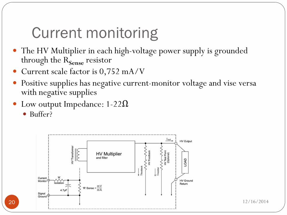
Current monitoring
12/16/2014 20
The HV Multiplier in each high-voltage power supply is grounded through the RSense resistor
Current scale factor is 0,752 mA/V
Positive supplies has negative current-monitor voltage and vise versa with negative supplies
Low output Impedance: 1-22Ω Buffer?

HV Board Bill of Materials
12/16/2014 21
Part Part Number Quantity Datasheet Price
Ultravolt Positive
HV-Module
4AA24-P20-H 2 http://www.ultravolt.com/uv_
docs/AASeriesDS.pdf
$514
Ultravolt Negative
HV-Module
4AA24-N20-H 2 http://www.ultravolt.com/app
lication_notes/TN-2.pdf
$514
Board Connector WM17723-ND
(Digikey)
4 http://www.molex.com/pdm_
docs/sd/015246180_sd.pdf
$1,78
Power connector WM18446-ND
(Digikey)
1 http://www.molex.com/pdm_
docs/sd/039303035_sd.pdf
$0,89

What still has to be done
12/16/2014 22
Can get rid of one DAC
The HV Enable/ Disable pins should be connected directly to
the GPIO pins
Pull up resistors has to be moved closer to the receiving pins.
Also more pull up resistors
Buffers for the low impedance current-monitor path
Current compensation in code

What is learnt during this Project
12/16/2014 23
HTML and CSS Web designing
The project page was the first one I used HTML
AutoCAD 2D mechanical designing tool
Autodesk Inventor 3D mechanical designing tool
Circuit designing
What not to do in next design