nirc am pupil imaging lens mechanism and optical …
TRANSCRIPT

NIRCAM PUPIL IMAGING LENS MECHANISM AND OPTICAL DESIGN
Charles S. Clark and Thomas Jamieson Lockheed Martin Advanced Technology Center
ABSTRACT
The Near Infrared Camera (NIRCam) instrument for NASA’s James Webb Space telescope (JWST) is one of four science instruments to be installed into the integrated science instrument module (ISIM) on JWST for the purpose of conducting scientific observations over a five year mission lifetime. NIRCam is required to operate at 37 Kelvin to produce high resolution images in two-wave bands ranging from 0.6 to5 microns. A relatively recent requirement for the NIRCam instrument is to provide a means of imaging the primary mirror for ground testing, instrument commissioning, and diagnostics throughout the mission. This paper discusses the development of the pupil imaging lens (PIL) assembly. In addition to detailing the driving requirements, this paper briefly covers the mechanism design and delves more deeply into the engineering of the optical design. Keywords: PIL, pupil imaging lens, mechanism, cryogenic mechanism, near infrared camera, NIRCam, James Webb, JWST
1 Introduction
1.1 PIL assembly overview The pupil imaging lens (PIL) assembly is one component within the NIRCam instrument, which is the primary imaging instrument on the James Webb Space Telescope. The main purpose of the PIL assembly is to form an image of the eighteen primary mirror segments of the JWST Telescope onto the NIRCam focal plane arrays (FPAs). NIRCam is the only instrument on the JWST observatory with wave front sensing (WFS) capability, and will use the PIL in conjunction with the WFS measurements. Furthermore, because wavefront sensing is performed around the 2 micron wavelength, the PIL optics were designated to be deployed within the NIRCam shortwave beam between the two fold mirrors and just before the FPA. The location of the PIL is shown in Figure 1. The actual mirror image is directed onto one of the four single chip arrays (SCAs) that populate a shortwave FPA. Operationally, the PIL assembly will introduce the pupil imaging lens into the shortwave beam of the NIRCam instrument several times during commissioning and on monthly intervals throughout the mission life.

Figure 1: Location of the PIL assembly within NIRCam module A bench.
1.2 Driving requirements There are many challenges in developing an optical mechanism for NIRCam. One difficulty is developing a lens system that alters the science prescription to create the appropriate image with a wavefront error of less than 75% Strehl, and a distortion of less than 2%. Another challenge is developing the optical mounts and the actuating mechanism to operate at 35 Kelvin. The mechanism also needs to perform the insertion repeatably to 40 microns with a maximum of 0.6 milli-Watts of power. There is an additional requirement that has been levied onto the PIL assembly that is unique with respect to all other NIRCam components. The PIL must perform operations in a fail-safe manner and not interfere with the science optics under any reasonable failure. These PIL assembly requirements, along with many others demand a unique opto-mechanical solution. Figure 2: The PIL assembly with functional call-outs.
Fail-safe spring
Position sensor track
Position sensors
Rotation hard stop
Counterweight (tungsten)
Stowage stop magnets
PIL bipod mounts to OBA
with locking cams
Actuator housing (titanium)
Optical arm (titanium) 125 mm
Ø150 mm B.C.
3-DOF Focus and alignment mechanism (FAM) with pick-off mirror
Filter wheel assemblies (FWA) •Spectral filters •Pupil wheel elements
Pupil imaging lens (PIL)
Beryllium optical bench assembly (OBA) 880 mm x 820 mm
Focal plane array (FPA)
2 PIL assembly mechanism design The PIL assembly design (Figure 2) consists of a titanium arm that integrates three lenses and an opposing tungsten counterweight. The arm rotates around a titanium fixed base that is mounted to the optical bench assembly (OBA) by a hexapod type of mount. The flexible hexapods are required to accommodate the differential temperature changes in the PIL with respect to the OBA which is made from beryllium. This arm is allowed to make only a partial rotation, and uses a precision ball bearing. This bearing, which uses a thin film of Teflon for lubrication at cryogenic temperatures, provides low friction, smooth motion and helps to maintain the tight positioning repeatability. The arm is actuated through its rotation by a redundantly wound, direct-drive, 3-phase servomotor that is mounted in the actuator body. The PIL assembly also incorporates a redundant inductive sensor system that provides position feedback to facilitate required motion smoothness as well as precise rotational position telemetry. The PIL assembly motors rotate the arm through about 120 degrees of rotation against a fail-safe spring until the arm makes a hard stop at the precise deployed position of the PIL optics. After completing the required operations with the optics deployed into the NIRCam short wavelength beam, the PIL arm is actuated back to the stowed position. The PIL is held in the stowed position, without power, by the fail-safe spring acting against a non-contact magnetic stowage stop. Through the use of the spring against the magnetic stowage stop, the PIL is held in the stowed position, unpowered, even through launch conditions. It is with this mechanism that the PIL optics are deployed with the required repeatability.
3 The PIL assembly optical design
3.1 The PIL optics goal A different way of stating that the PIL optics must make an image of the JWST telescope primary would be to say that the PIL optics must image the telescope’s pupil. There are, however, a number of optical pupils throughout the JWST optical system. These pupils are the positions in space where chief rays from all field points “intersect”. Three of the pupils are as follows:
1. Primary mirror – JWST entrance pupil 2. Fine steering mirror (FSM) – intermediate pupil created by TMA 3. NIRCam pupil wheel – exit pupil controlled by the pick-off-mirror (POM)
We recall the optical duality between images and pupils in general optical systems. In “normal” imagery we progress from object via entrance pupil to image via intermediate pupil to relay optics to final image surface. In the NIRCam “conventional” imaging process we have: Object (Cosmos) – Entrance Pupil (Primary Mirror) – Image (POM) – Pupil Wheel – Focal plane array. In the NIRCam pupil imaging process we have: Object (primary mirror) – Image (FSM) – Pupil (POM) – Image (pupil wheel) added PIL to create an image on the FPA. Therefore, the PIL optics have been designed into the short wavelength beam after the pupil wheel. After reviewing the NIRCam imager layout in Figure 3, it is obvious that the PIL optics should be positioned between the two fold mirrors just before the FPA.

Figure 3: NIRCam shortwave optical system.
3.2 PIL optics driving requirements Once it was decided that a PIL was to be inserted into the short wavelength beam of the NIRCam instrument, a set of requirements was generated to define the performance of the optical system. A summary of the agreed upon driving requirements are listed in Table 1.
Optical requirement Required performance Notes
Spectral band Filter F187N i.e. 1.87 microns ± 1%
Transmission 80%
Boresight 10 arcsec
Image quality > 75% Strehl
Distortion < 2%
Image size > 1500 and < 2000 pixels
Clear aperture 25 mm
Physical size 35 +0.0,-0.01 mm Table 1: NIRCam Pupil imager optical specifications. There were a number of basic optical design parameters for the PIL optics. The first design parameter was that the NIRCam PIL shall be designed to give an image of the primary mirror with a single star source within 10 arc-sec of the PIL boresight. The second design parameter was that the diameter for the PIL is set by the size of the unvignetted field. The third design parameter was the magnification of the PIL optics.
NIRCam Mono OTE 03/02/04 12-Jan-05
125.00 MM
NIRCam imager
1 POM to FPA
POM (image)
FPA (image)
NIRCam wheel (pupil)

The fact that the primary mirror image is to be placed on a single chip array (SCA), which is one quadrant of the FPA and contains 2k x 2k pixels, implies a magnification of 0.0041. The fourth design parameter was the lens material. Fused silica was chosen for the PIL optics because the system operates over a narrow waveband (Filter F187N) which implies that no chromatic correction is required. Some additional design parameters were that the field of view of the PIL optics is the primary mirror, and that the aperture stop for pupil imagery is the PIL lens group.
3.3 Engineering the PIL optics solution In order to design an optical system that meets the list of requirements, the first choice was a single spherical lens design (Figure 4). The single spherical lens was located between the last two fold mirrors before the FPA in the short wavelength beam. NIRCam Figure 4: NIRCam optics section with single spherical PIL lens. A detailed analysis of using a single spherical lens as the PIL optics showed completely unacceptable performance. The transverse ray aberrations of the single spherical lens design had gross astigmatism as shown in Figure 5.
NIRCam Mono OTE 03/02/04 Scale: 0.40 12-Jan-05
62.50 MM
NIRCam optical section ─ pupil wheel to FPA
Pupil imaging lens (PIL) simplest implementation
single spherical lens
NIRCam pupil wheel
PIL spherical lens in correct magnification location
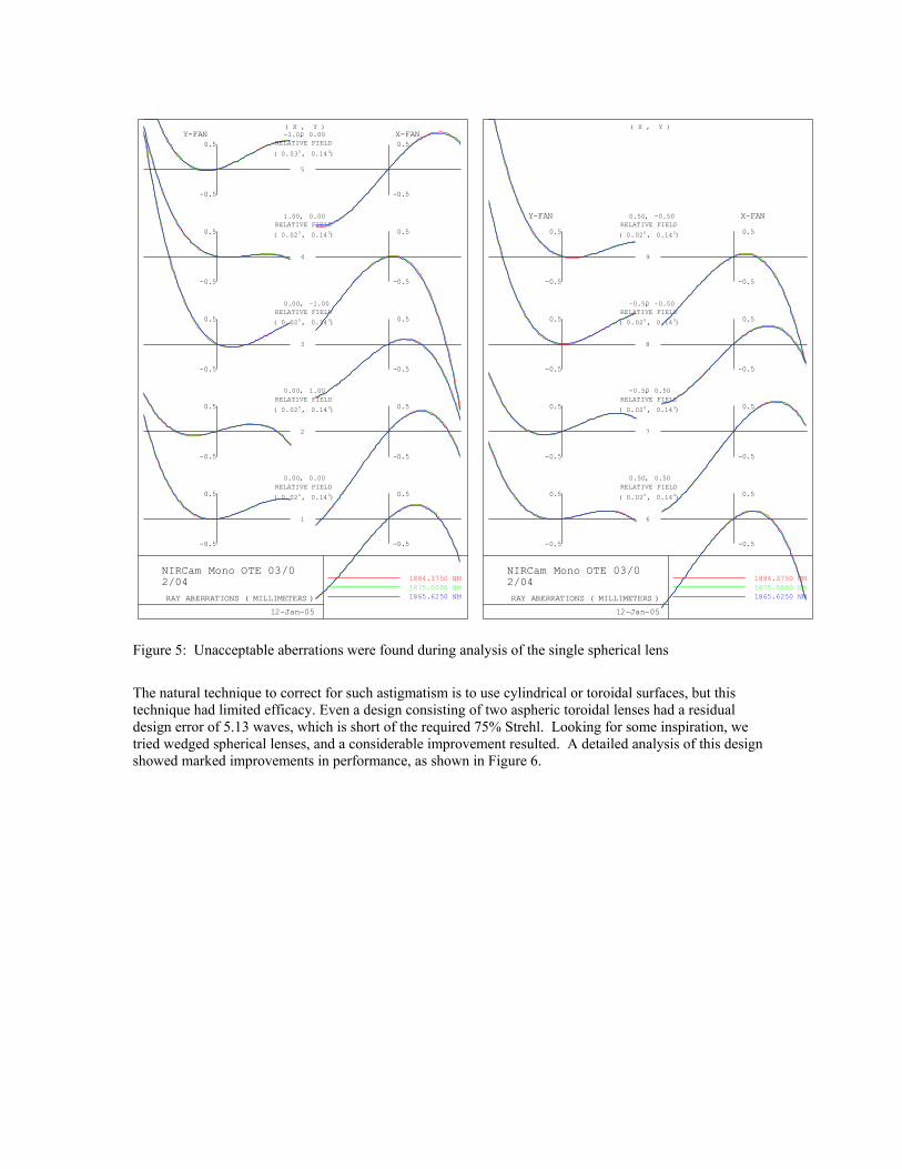
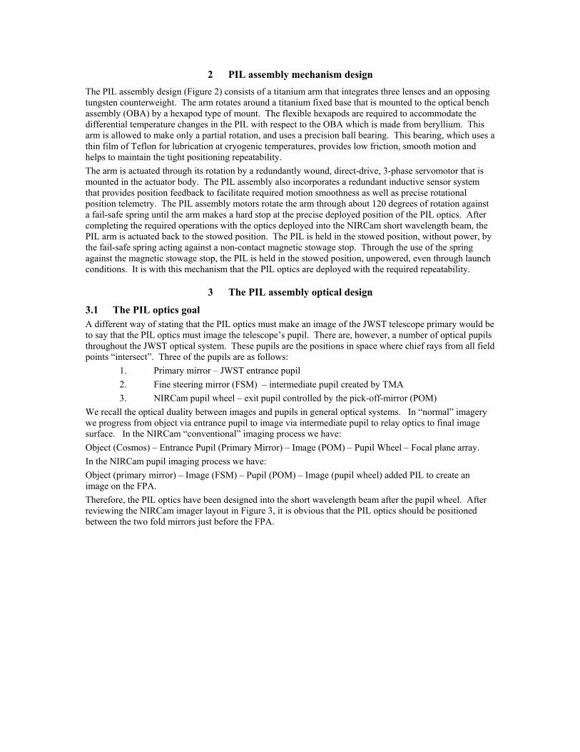
Figure 5: Unacceptable aberrations were found during analysis of the single spherical lens The natural technique to correct for such astigmatism is to use cylindrical or toroidal surfaces, but this technique had limited efficacy. Even a design consisting of two aspheric toroidal lenses had a residual design error of 5.13 waves, which is short of the required 75% Strehl. Looking for some inspiration, we tried wedged spherical lenses, and a considerable improvement resulted. A detailed analysis of this design showed marked improvements in performance, as shown in Figure 6.
12-Jan-05
NIRCam Mono OTE 03/02/04 RAY ABERRATIONS ( MILLIMETERS )
1884.3750 NM 1875.0000 NM 1865.6250 NM
-0.5
0.5
1
-0.5
0.5
, 0.00 0.00RELATIVE FIELD
( , )0.02O 0.14 O
-0.5
0.5
2
-0.5
0.5
, 0.00 1.00RELATIVE FIELD
( , )0.02O 0.14 O
-0.5
0.5
3
-0.5
0.5
, 0.00 -1.00RELATIVE FIELD
( , )0.02O 0.14 O
-0.5
0.5
4
-0.5
0.5
, 1.00 0.00RELATIVE FIELD
( , )0.02O 0.14 O
-0.5
0.5
5
-0.5
0.5
( X , Y ) Y-FAN , -1.00 0.00
RELATIVE FIELD
( , )0.03O 0.14 O
X-FAN
12-Jan-05
NIRCam Mono OTE 03/02/04 RAY ABERRATIONS ( MILLIMETERS )
1884.3750 NM 1875.0000 NM 1865.6250 NM
-0.5
0.5
6
-0.5
0.5
, 0.50 0.50RELATIVE FIELD
( , )0.02O 0.14 O
-0.5
0.5
7
-0.5
0.5
, -0.50 0.50RELATIVE FIELD
( , )0.02O 0.14 O
-0.5
0.5
8
-0.5
0.5
, -0.50 -0.50RELATIVE FIELD
( , )0.02O 0.14 O
-0.5
0.5
9
-0.5
0.5
( X , Y )
Y-FAN , 0.50 -0.50RELATIVE FIELD
( , )0.02O 0.14 O
X-FAN

Figures 6: Transverse ray aberrations of various field points in image of circumscribed primary on FPA. Further refinement of the PIL design required finding a balance between PIL optical size and the aperture stop. The use of the POM as an aperture stop resulted in very large diameters of the PIL lens elements (Figure 7), and a refinement was to locate the aperture stop within the PIL group itself (Figure 8). This however led to some vignetting at the edge of the PIL field of view. It was ultimately agreed that the system could handle the small amount of vignetting to gain the advantage of having smaller lens elements. Figure 7: PIL optical design with POM as aperture stop. Figure 8: Aperture stop within the PIL group.
NIRCam Mono OTE 03/02/04 Scale: 0.20 12-Jan-05
125.00 MM
NIRCam Mono OTE 03/02/04 Scale: 0.20 12-Jan-05
125.00 MM
F/14 beams from POM must be
stopped down. Place limiting stop
on PIL
12-Jan-05
NIRCam Mono OTE 03/02/04 RAY ABERRATIONS ( MILLIMETERS )
1884.3750 NM 1875.0000 NM 1865.6250 NM
-0.05
0.05
1
-0.05
0.05
, 0.00 0.00RELATIVE FIELD
( , )0.01O 0.15 O
-0.05
0.05
2
-0.05
0.05
, 0.00 1.00RELATIVE FIELD
( , )0.01O 0.14 O
-0.05
0.05
3
-0.05
0.05
, 0.00 -1.00RELATIVE FIELD
( , )0.01O 0.15 O
-0.05
0.05
4
-0.05
0.05
, 1.00 0.00RELATIVE FIELD
( , )0.01O 0.15 O
-0.05
0.05
5
-0.05
0.05
( X , Y ) Y-FAN , -1.00 0.00
RELATIVE FIELD
( , )0.02O 0.15 O
X-FAN
12-Jan-05
NIRCam Mono OTE 03/02/04 RAY ABERRATIONS ( MILLIMETERS )
1884.3750 NM 1875.0000 NM 1865.6250 NM
-0.05
0.05
6
-0.05
0.05
, 0.50 0.50RELATIVE FIELD
( , )0.01O 0.14 O
-0.05
0.05
7
-0.05
0.05
, -0.50 0.50RELATIVE FIELD
( , )0.02O 0.14 O
-0.05
0.05
8
-0.05
0.05
, -0.50 -0.50RELATIVE FIELD
( , )0.02O 0.15 O
-0.05
0.05
9
-0.05
0.05
( X , Y )
Y-FAN , 0.50 -0.50RELATIVE FIELD
( , )0.01O 0.15 O
X-FAN

After this analysis, the PIL optical design team felt the dual wedged spherical lens system ( Figure 9) was very close to meeting all of the required performance parameters.
Figure 9: PIL dual wedged spherical lens design.
Unfortunately, the team found there was yet another performance aspect that needed to be addressed. Analysis of the PIL optics showed that while there was only 1% distortion of the image, there was approximately 10% anamorphism (i.e. differential magnification in perpendicular directions). The design team believed this to be acceptable since we expected such anamorphism could easily be removed in software image processing. However, after reviewing the distortion requirements with the JWST science team, it was agreed that the PIL optics distortion of the image should be less than 2%, and this should include all distortion types. Figure 10 shows the anamorphic distortion of the circumference of the primary mirror from the dual wedged spherical lens design.
Figure 10: Anamorphic image produced by dual wedged spherical lens design.
Modification of the dual wedged spherical lens system failed to meet this requirement. Addition of a third element was the only choice. It is with the addition of the third lens, with one planar and one cylindrical surface, that the PIL optics achieved the required performance.

3.4 Final PIL optical configuration At the outset, the development of the PIL optical design was never considered to be trivial; however, the design team found the task of developing an optical system for the PIL to be quite a challenge. The combination of image deformation, wavefront error, distortion, and other requirements called for a unique optical solution.
Figure 11: PIL three lens optical system. The three lens system (Figure 11) with two wedged spherical lenses and one plane cylinder lens was developed through an iterative process, and in the end, the system was analyzed to meet the stringent requirements (Table 2).
Optical requirement Required performance Three lens optical performance
Spectral band Filter F187N 1.87 microns
Transmission 80% expected
Boresight 10 arcsec 10 arcsec radial
Image quality > 75% Strehl 88–98%
Distortion < 2% < 1.5%
Image size > 1500 and < 2000 pixels 1620 pixels
Clear aperture 25 mm > 25 mm
Physical size 35 +0.0,-0.01 mm in work
Table 2: PIL optical system performance analysis summary
4 Conclusion The pupil imaging lens assembly has been developed to meet a challenging set of requirements. On one hand, there is the design of a mechanism that can rotate payloads to a fine repeatability within a cryogenic environment. Then there is the design of one set of lenses that, once inserted, can drastically alter the prescription of a telescope. Furthermore, the optical system must have exceptional performance over a wide range of parameters. The design team has successfully shown that the PIL precision mechanism and optical design support this demanding set of requirements.
3x Convex
Concave
Planar
Convex cylindrical
surface