nissan frontier 2 & 4wd king & crew cab models … · nissan frontier 2 & 4wd automatic...
TRANSCRIPT
3651 N Highway 89 • Chino Valley, AZ 86323(928) 636-7080 • www.p-a-g.net
NISSAN FRONTIER 2 & 4WDAUTOMATIC & MANUAL TRANS.KING & CREW CAB MODELS3” BODY LIFT KITINSTALLATION INSTRUCTIONS2005-2011 KIT# 40083
WARNING
Installation of a Performance Automotive Group bodylift kit will change the vehicle’s center of gravity andhandling characteristics both on- and off-road. Youmust drive the vehicle safely! Extreme care must betaken to prevent vehicle rollover or loss of control,which could result in serious injury or death. Avoid sud-den sharp turns or abrupt maneuvers and always makesure all vehicle occupants have their seat belts fas-tened.
WARNING
Before you install this kit, read and understand allinstructions, warnings, cautions, and notes in thisinstruction sheet and in the vehicle owner’s manual.
CAUTION
Proper installation of this kit requires knowledge of thefactory recommended procedures for removal andinstallation of original equipment components. We rec-ommend that the factory shop manual and any specialtools needed to service your vehicle be on hand duringthe installation. Installation of this kit without properknowledge of the factory recommended proceduresmay affect the performance of these components andthe safety of the vehicle. We strongly recommend thata certified mechanic familiar with the installation of sim-ilar components install this kit.
WARNING
DO NOT combine suspension, body, or other liftdevices. Use of vehicle with combined lifts may resultin unsafe and/or unexpected handling characteristics.
WARNING
This kit should only be installed on a vehicle that is ingood working condition. Before you install the kit, thor-oughly inspect the vehicle for corrosion or deformationof the sheet metal around the factory body mounts. Ifthe vehicle is suspected to have been in a collision ormisused, do not install this kit. Off-road use of yourvehicle with this kit installed may increase the stressapplied to the factory body mounts. We do not recom-mend that any vehicle with a body lift kit installed beinvolved in any extreme off-road maneuvers such asjumping. Failure to observe this warning may result inserious personal injury and/or severe damage to yourvehicle.
WARNING
Many states and municipalities have laws restrictingbumper heights and vehicle lifts. Consult state andlocal laws to determine if the changes you intend tomake to the vehicle comply with the law.
WARNING
The installation of larger tires may reduce the effective-ness of the braking system.
WARNING
Always wear eye protection when operating powertools.
WARNING
Before you install this kit, block the vehicle tires to pre-vent the vehicle from rolling.
WARNING
Accidental deployment of the air bag can result in seri-ous personal injury or death. To avoid accidentaldeployment during installation of the kit, the Supple-mental Restraint System (SRS, or airbag) must remaindeactivated. Do not allow anyone near the airbag dur-ing installation. Refer to the factory service manual orowner's manual for the recommended procedure todisable the SRS. After you install the kit, reactivate theSRS before driving the vehicle.
NOTE
Performance Automotive Group recommends usingthe Loctite® supplied in the kit on the threads of all kitnuts and bolts unless specified otherwise in theseinstructions.
1 Frontier - Kit 40083
2 Frontier - Kit 40083
Before Starting Installation
1. Carefully read all warnings and instructions com-pletely before beginning.
2. Verify all parts have been received in this kit bychecking the parts list at the end of this document.
3. Only install this kit on the vehicle for which it isspecified. If anytime during the installation youencounter something different from what is outlinedin the instructions, call technical support at (928)636-7080.
4. Special tools needed:
a. Welder or access to a professional weldingshop.
b. Die grinder or similar tool capable of cuttingmetal.
c. Saws All or similar reciprocating cutting bladetool.
5. Park vehicle on a clean, dry, flat, level surface andblock tires so vehicle cannot roll in either direction.
NOTE
Kit parts are prefaced by the word kit and appear inbold print.
NOTE
If parts are missing from kit, please be prepared to pro-vide the following information:
1. Name of purchase location2. Bar Code on side of box3. Date above bar code4. Date inside box cover5. Inspector # from inside box cover
Engine Compartment
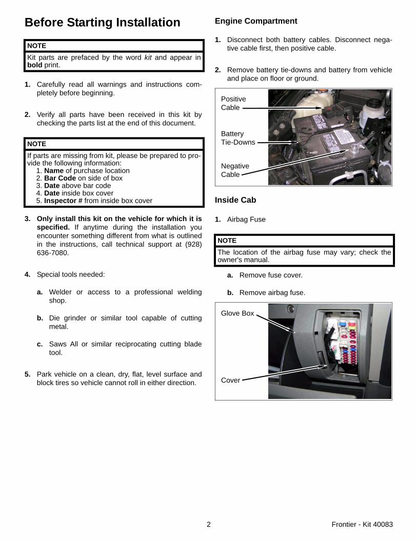
1. Disconnect both battery cables. Disconnect nega-tive cable first, then positive cable.
2. Remove battery tie-downs and battery from vehicleand place on floor or ground.
Inside Cab
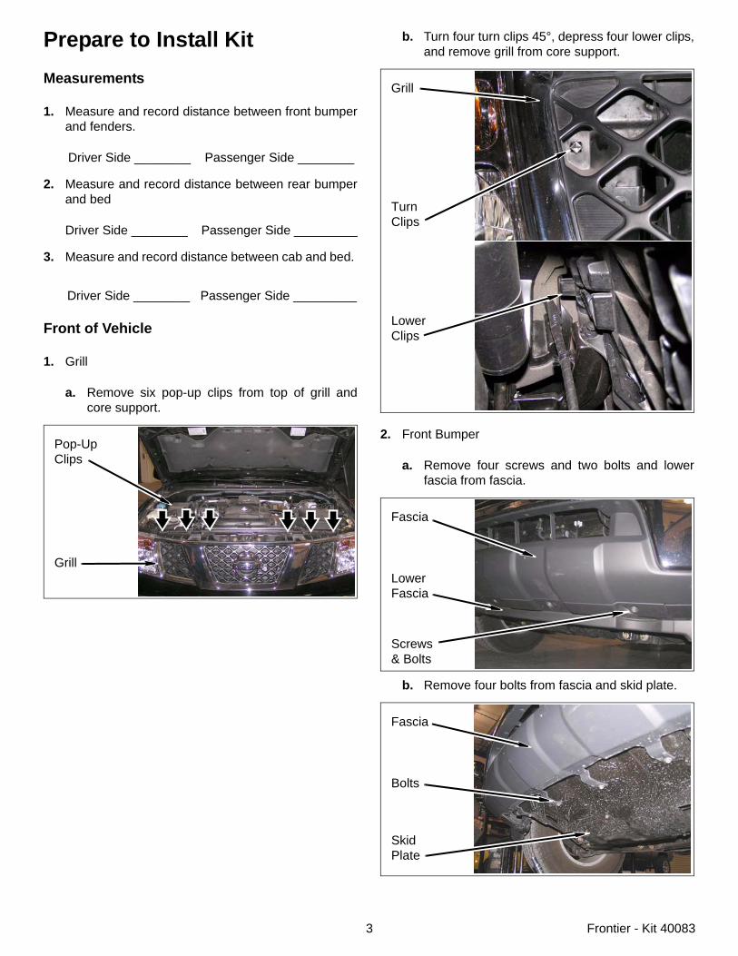
1. Airbag Fuse
a. Remove fuse cover.
b. Remove airbag fuse.
NOTE
The location of the airbag fuse may vary; check theowner's manual.
PositiveCable
BatteryTie-Downs
NegativeCable
Glove Box
Cover
3 Frontier - Kit 40083
Prepare to Install KitMeasurements
1. Measure and record distance between front bumperand fenders.
Driver Side ________ Passenger Side ________
2. Measure and record distance between rear bumperand bed
Driver Side ________ Passenger Side _________
3. Measure and record distance between cab and bed.
Driver Side ________ Passenger Side _________
Front of Vehicle
1. Grill
a. Remove six pop-up clips from top of grill andcore support.
Pop-UpClips
Grill
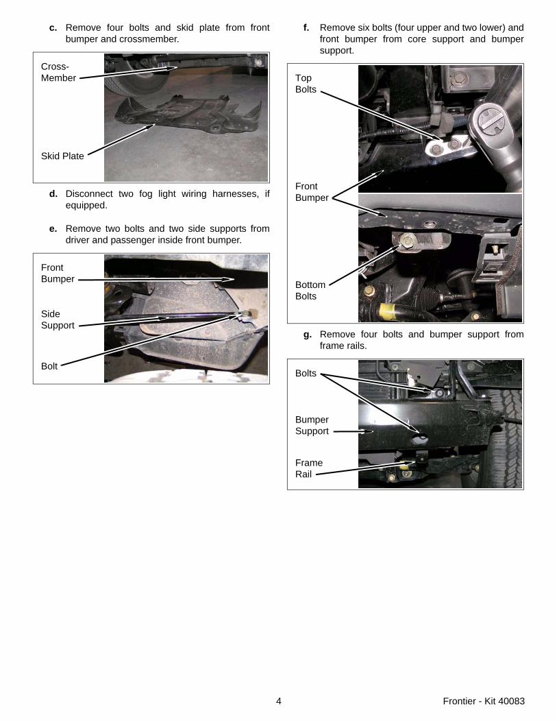
b. Turn four turn clips 45°, depress four lower clips,and remove grill from core support.
2. Front Bumper
a. Remove four screws and two bolts and lowerfascia from fascia.
b. Remove four bolts from fascia and skid plate.
Grill
LowerClips
TurnClips
Fascia
LowerFascia
Screws& Bolts
Fascia
Bolts
SkidPlate
4 Frontier - Kit 40083
c. Remove four bolts and skid plate from frontbumper and crossmember.
d. Disconnect two fog light wiring harnesses, ifequipped.
e. Remove two bolts and two side supports fromdriver and passenger inside front bumper.
Cross-Member
Skid Plate
FrontBumper
SideSupport
Bolt
f. Remove six bolts (four upper and two lower) andfront bumper from core support and bumpersupport.
g. Remove four bolts and bumper support fromframe rails.
TopBolts
FrontBumper
BottomBolts
Bolts
BumperSupport
FrameRail
5 Frontier - Kit 40083
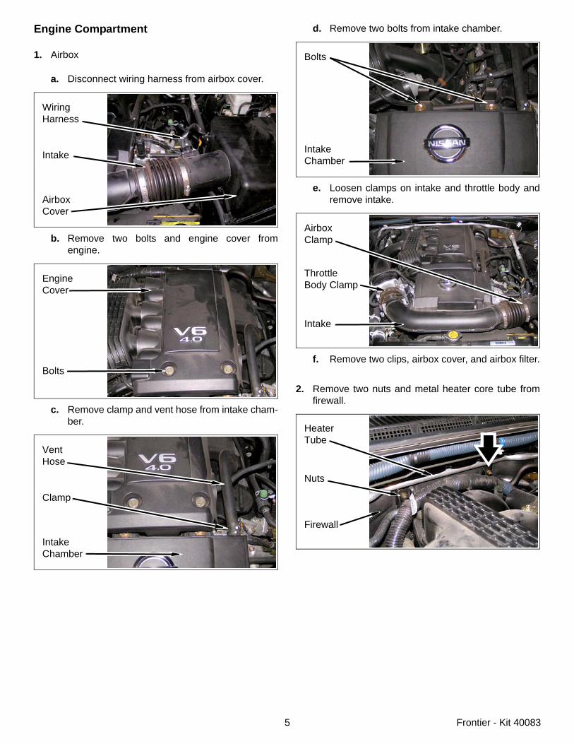
Engine Compartment
1. Airbox
a. Disconnect wiring harness from airbox cover.
b. Remove two bolts and engine cover fromengine.
c. Remove clamp and vent hose from intake cham-ber.
WiringHarness
Intake
AirboxCover
EngineCover
Bolts
VentHose
Clamp
IntakeChamber
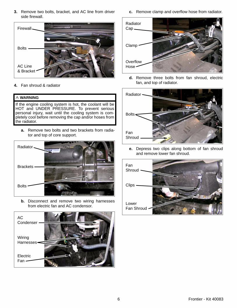
d. Remove two bolts from intake chamber.
e. Loosen clamps on intake and throttle body andremove intake.
f. Remove two clips, airbox cover, and airbox filter.
2. Remove two nuts and metal heater core tube fromfirewall.
Bolts
IntakeChamber
ThrottleBody Clamp
Intake
AirboxClamp
Firewall
HeaterTube
Nuts
6 Frontier - Kit 40083
3. Remove two bolts, bracket, and AC line from driverside firewall.
4. Fan shroud & radiator
a. Remove two bolts and two brackets from radia-tor and top of core support.
b. Disconnect and remove two wiring harnessesfrom electric fan and AC condensor.
WARNING
If the engine cooling system is hot, the coolant will beHOT and UNDER PRESSURE. To prevent seriouspersonal injury, wait until the cooling system is com-pletely cool before removing the cap and/or hoses fromthe radiator.
Firewall
Bolts
AC Line& Bracket
Radiator
Brackets
Bolts
ACCondenser
WiringHarnesses
ElectricFan
c. Remove clamp and overflow hose from radiator.
d. Remove three bolts from fan shroud, electricfan, and top of radiator.
e. Depress two clips along bottom of fan shroudand remove lower fan shroud.
RadiatorCap
Clamp
OverflowHose
Radiator
Bolts
FanShroud
FanShroud
Clips
LowerFan Shroud
7 Frontier - Kit 40083
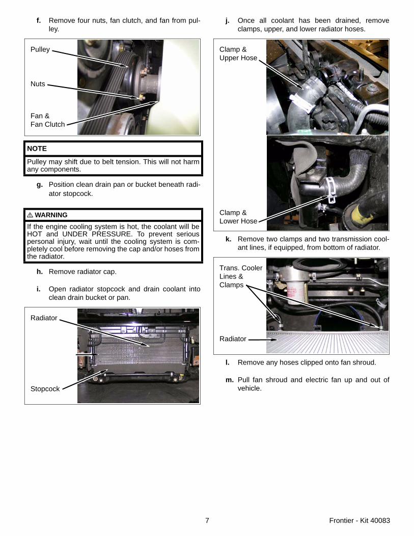
f. Remove four nuts, fan clutch, and fan from pul-ley.
g. Position clean drain pan or bucket beneath radi-ator stopcock.
h. Remove radiator cap.
i. Open radiator stopcock and drain coolant intoclean drain bucket or pan.
NOTE
Pulley may shift due to belt tension. This will not harmany components.
WARNING
If the engine cooling system is hot, the coolant will beHOT and UNDER PRESSURE. To prevent seriouspersonal injury, wait until the cooling system is com-pletely cool before removing the cap and/or hoses fromthe radiator.
Pulley
Nuts
Fan &Fan Clutch
Radiator
Stopcock
j. Once all coolant has been drained, removeclamps, upper, and lower radiator hoses.
k. Remove two clamps and two transmission cool-ant lines, if equipped, from bottom of radiator.
l. Remove any hoses clipped onto fan shroud.
m. Pull fan shroud and electric fan up and out ofvehicle.
Clamp &Upper Hose
Clamp &Lower Hose
Trans. CoolerLines & Clamps
Radiator
8 Frontier - Kit 40083
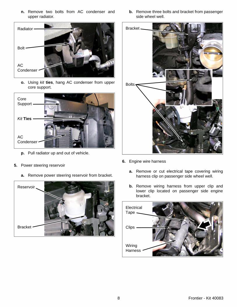
n. Remove two bolts from AC condenser andupper radiator.
o. Using kit ties, hang AC condenser from uppercore support.
p. Pull radiator up and out of vehicle.
5. Power steering reservoir
a. Remove power steering reservoir from bracket.
ACCondenser
Bolt
Radiator
CoreSupport
Kit Ties
ACCondenser
Reservoir
Bracket
b. Remove three bolts and bracket from passengerside wheel well.
6. Engine wire harness
a. Remove or cut electrical tape covering wiringharness clip on passenger side wheel well.
b. Remove wiring harness from upper clip andlower clip located on passenger side enginebracket.
Bracket
Bolts
ElectricalTape
Clips
WiringHarness
9 Frontier - Kit 40083
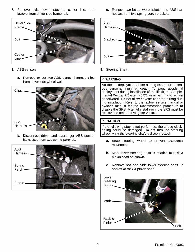
7. Remove bolt, power steering cooler line, andbracket from driver side frame rail.
8. ABS sensors
a. Remove or cut two ABS sensor harness clipsfrom driver side wheel well.
b. Disconnect driver and passenger ABS sensorharnesses from two spring perches.
Driver SideFrame
Bolt
CoolerLine
Clips
ABSHarness
ABSHarness
SpringPerch
Frame
c. Remove two bolts, two brackets, and ABS har-nesses from two spring perch brackets.
9. Steering Shaft
a. Strap steering wheel to prevent accidentalmovement.
b. Mark lower steering shaft in relation to rack &pinion shaft as shown.
c. Remove bolt and slide lower steering shaft upand off of rack & pinion shaft.
WARNING
Accidental deployment of the air bag can result in seri-ous personal injury or death. To avoid accidentaldeployment during installation of the lift kit, the Supple-mental Restraint System (SRS, or airbag) must remaindeactivated. Do not allow anyone near the airbag dur-ing installation. Refer to the factory service manual orowner's manual for the recommended procedure todisable the SRS. After kit installation, the SRS must bereactivated before driving the vehicle.
CAUTION
If the following step is not performed, the airbag clock-spring could be damaged. Do not turn the steeringwheel while the steering shaft is disconnected.
ABSHarness
Bracket
Bolt
LowerSteeringShaft
Mark
Bolt
Rack &Pinion
10 Frontier - Kit 40083
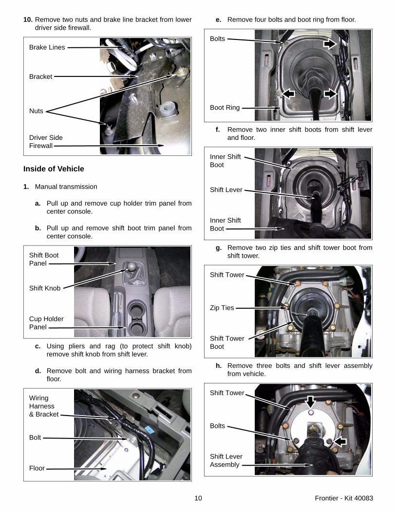
10. Remove two nuts and brake line bracket from lowerdriver side firewall.
Inside of Vehicle
1. Manual transmission
a. Pull up and remove cup holder trim panel fromcenter console.
b. Pull up and remove shift boot trim panel fromcenter console.
c. Using pliers and rag (to protect shift knob)remove shift knob from shift lever.
d. Remove bolt and wiring harness bracket fromfloor.
Brake Lines
Bracket
Driver SideFirewall
Nuts
Shift BootPanel
Shift Knob
Cup HolderPanel
WiringHarness& Bracket
Bolt
Floor
e. Remove four bolts and boot ring from floor.
f. Remove two inner shift boots from shift leverand floor.
g. Remove two zip ties and shift tower boot fromshift tower.
h. Remove three bolts and shift lever assemblyfrom vehicle.
Bolts
Boot Ring
Inner ShiftBoot
Shift Lever
Inner ShiftBoot
Shift Tower
Zip Ties
Shift TowerBoot
Shift Tower
Bolts
Shift LeverAssembly
11 Frontier - Kit 40083
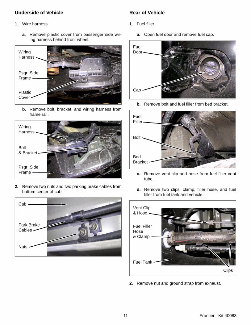
Underside of Vehicle
1. Wire harness
a. Remove plastic cover from passenger side wir-ing harness behind front wheel.
b. Remove bolt, bracket, and wiring harness fromframe rail.
2. Remove two nuts and two parking brake cables frombottom center of cab.
WiringHarness
Psgr. Side Frame
PlasticCover
WiringHarness
Bolt& Bracket
Psgr. SideFrame
Cab
Park BrakeCables
Nuts
Rear of Vehicle
1. Fuel filler
a. Open fuel door and remove fuel cap.
b. Remove bolt and fuel filler from bed bracket.
c. Remove vent clip and hose from fuel filler venttube.
d. Remove two clips, clamp, filler hose, and fuelfiller from fuel tank and vehicle.
2. Remove nut and ground strap from exhaust.
FuelDoor
Cap
FuelFiller
Bolt
BedBracket
Vent Clip& Hose
Fuel FillerHose& Clamp
Fuel Tank
Clips
12 Frontier - Kit 40083
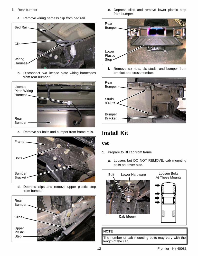
3. Rear bumper
a. Remove wiring harness clip from bed rail.
b. Disconnect two license plate wiring harnessesfrom rear bumper.
c. Remove six bolts and bumper from frame rails.
d. Depress clips and remove upper plastic stepfrom bumper.
Bed Rail
Clip
WiringHarness
LicensePlate Wiring Harness
RearBumper
Frame
Bolts
BumperBracket
RearBumper
Clips
UpperPlasticStep
e. Depress clips and remove lower plastic stepfrom bumper.
f. Remove six nuts, six studs, and bumper frombracket and crossmember.
Install KitCab
1. Prepare to lift cab from frame
a. Loosen, but DO NOT REMOVE, cab mountingbolts on driver side.
NOTE
The number of cab mounting bolts may vary with thelength of the cab.
RearBumper
LowerPlasticStep
RearBumper
Studs& Nuts
BumperBracket
Cab Mount
Loosen BoltsAt These Mounts
Bolt Lower Hardware
13 Frontier - Kit 40083
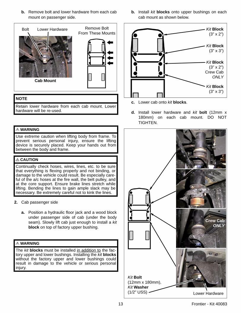
b. Remove bolt and lower hardware from each cabmount on passenger side.
2. Cab passenger side
a. Position a hydraulic floor jack and a wood blockunder passenger side of cab (under the bodyseam). Slowly lift cab just enough to install a kitblock on top of factory upper bushing.
NOTE
Retain lower hardware from each cab mount. Lowerhardware will be re-used.
WARNING
Use extreme caution when lifting body from frame. Toprevent serious personal injury, ensure the liftingdevice is securely placed. Keep your hands out frombetween the body and frame.
CAUTION
Continually check hoses, wires, lines, etc. to be surethat everything is flexing properly and not binding, ordamage to the vehicle could result. Be especially care-ful of the a/c hoses at the fire wall, the belt pulley, andat the core support. Ensure brake lines stretch whilelifting. Bending the lines to gain ample slack may benecessary. Be extremely careful not to kink the lines.
WARNING
The kit blocks must be installed in addition to the fac-tory upper and lower bushings. Installing the kit blockswithout the factory upper and lower bushings couldresult in damage to the vehicle or serious personalinjury.
Remove BoltFrom These Mounts
Bolt Lower Hardware
Cab Mount
b. Install kit blocks onto upper bushings on eachcab mount as shown below.
c. Lower cab onto kit blocks.
d. Install lower hardware and kit bolt (12mm x180mm) on each cab mount. DO NOTTIGHTEN.
Kit Block(3” x 2”)
Kit Block(3” x 2”)
Crew CabONLY
Kit Block(3” x 3”)
Kit Block(3” x 3”)
Kit Bolt(12mm x 180mm),Kit Washer(1/2” USS) Lower Hardware
Crew CabONLY
14 Frontier - Kit 40083
3. Cab driver side
a. Repeat previous steps on driver side of cab.
b. Set cab-to-bed spacing according to previousmeasurement.
c. Remove each kit bolt, one at a time, and apply asmall amount of kit Loctite® onto threads.Install kit bolt, kit washer (1/2” USS), and lowerhardware. TIGHTEN kit bolt to 55 ft. lbs.
Bed
1. Prepare to lift bed from frame
a. Loosen, but DO NOT REMOVE, bed mountingbolts on driver side.
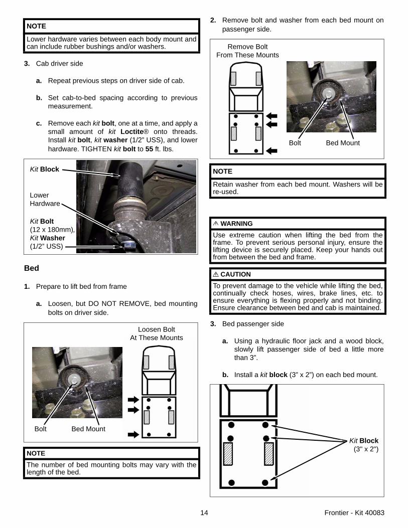
NOTE
Lower hardware varies between each body mount andcan include rubber bushings and/or washers.
NOTE
The number of bed mounting bolts may vary with thelength of the bed.
Kit Bolt(12 x 180mm),Kit Washer(1/2” USS)
LowerHardware
Kit Block
Loosen BoltAt These Mounts
Bolt Bed Mount
2. Remove bolt and washer from each bed mount onpassenger side.
3. Bed passenger side
a. Using a hydraulic floor jack and a wood block,slowly lift passenger side of bed a little morethan 3”.
b. Install a kit block (3” x 2”) on each bed mount.
NOTE
Retain washer from each bed mount. Washers will bere-used.
WARNING
Use extreme caution when lifting the bed from theframe. To prevent serious personal injury, ensure thelifting device is securely placed. Keep your hands outfrom between the bed and frame.
CAUTION
To prevent damage to the vehicle while lifting the bed,continually check hoses, wires, brake lines, etc. toensure everything is flexing properly and not binding.Ensure clearance between bed and cab is maintained.
Remove BoltFrom These Mounts
Bolt Bed Mount
Kit Block(3" x 2")
15 Frontier - Kit 40083
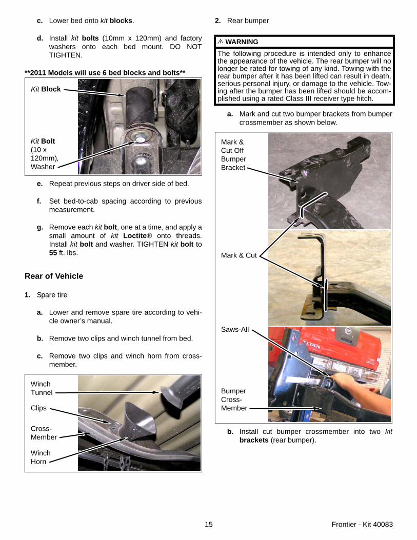
c. Lower bed onto kit blocks.
d. Install kit bolts (10mm x 120mm) and factorywashers onto each bed mount. DO NOTTIGHTEN.
**2011 Models will use 6 bed blocks and bolts**
e. Repeat previous steps on driver side of bed.
f. Set bed-to-cab spacing according to previousmeasurement.
g. Remove each kit bolt, one at a time, and apply asmall amount of kit Loctite® onto threads.Install kit bolt and washer. TIGHTEN kit bolt to55 ft. lbs.
Rear of Vehicle
1. Spare tire
a. Lower and remove spare tire according to vehi-cle owner’s manual.
b. Remove two clips and winch tunnel from bed.
c. Remove two clips and winch horn from cross-member.
Kit Bolt(10 x 120mm),Washer
Kit Block
WinchTunnel
Clips
WinchHorn
Cross-Member
2. Rear bumper
a. Mark and cut two bumper brackets from bumpercrossmember as shown below.
b. Install cut bumper crossmember into two kitbrackets (rear bumper).
WARNING
The following procedure is intended only to enhancethe appearance of the vehicle. The rear bumper will nolonger be rated for towing of any kind. Towing with therear bumper after it has been lifted can result in death,serious personal injury, or damage to the vehicle. Tow-ing after the bumper has been lifted should be accom-plished using a rated Class III receiver type hitch.
Mark &Cut OffBumperBracket
BumperCross-Member
Saws-All
Mark & Cut
16 Frontier - Kit 40083
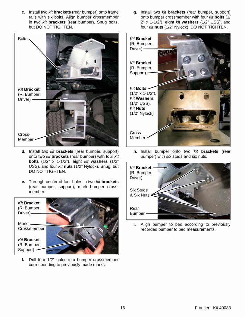
c. Install two kit brackets (rear bumper) onto framerails with six bolts. Align bumper crossmemberin two kit brackets (rear bumper). Snug bolts,but DO NOT TIGHTEN.
d. Install two kit brackets (rear bumper, support)onto two kit brackets (rear bumper) with four kitbolts (1/2” x 1-1/2”), eight kit washers (1/2”USS), and four kit nuts (1/2” Nylock). Snug, butDO NOT TIGHTEN.
e. Through center of four holes in two kit brackets(rear bumper, support), mark bumper cross-member.
f. Drill four 1/2” holes into bumper crossmembercorresponding to previously made marks.
Bolts
Kit Bracket(R. Bumper,Driver)
Cross-Member
MarkCrossmember
Kit Bracket(R. Bumper,Support)
Kit Bracket(R. Bumper,Driver)
g. Install two kit brackets (rear bumper, support)onto bumper crossmember with four kit bolts (1/2” x 1-1/2”), eight kit washers (1/2” USS), andfour kit nuts (1/2” Nylock). DO NOT TIGHTEN.
h. Install bumper onto two kit brackets (rearbumper) with six studs and six nuts.
i. Align bumper to bed according to previouslyrecorded bumper to bed measurements.
Kit Bracket(R. Bumper,Driver)
Cross-Member
Kit Bolts(1/2” x 1-1/2”),Kit Washers(1/2” USS),Kit Nuts(1/2” Nylock)
Kit Bracket(R. Bumper,Support)
Six Studs& Six Nuts
RearBumper
Kit Bracket(R. Bumper,Driver)
17 Frontier - Kit 40083
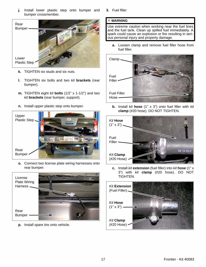
j. Install lower plastic step onto bumper andbumper crossmember.
k. TIGHTEN six studs and six nuts.
l. TIGHTEN six bolts and two kit brackets (rearbumper).
m. TIGHTEN eight kit bolts (1/2” x 1-1/2”) and twokit brackets (rear bumper, support).
n. Install upper plastic step onto bumper.
o. Connect two license plate wiring harnesses ontorear bumper.
p. Install spare tire onto vehicle.
RearBumper
LowerPlastic Step
UpperPlastic Step
RearBumper
LicensePlate Wiring Harness
RearBumper
3. Fuel filler
a. Loosen clamp and remove fuel filler hose fromfuel filler.
b. Install kit hose (1” x 3”) onto fuel filler with kitclamp (#20 hose). DO NOT TIGHTEN.
c. Install kit extension (fuel filler) into kit hose (1” x3”) with kit clamp (#20 hose). DO NOTTIGHTEN.
WARNING
Use extreme caution when working near the fuel linesand the fuel tank. Clean up spilled fuel immediately. Aspark could cause an explosion or fire resulting in seri-ous personal injury and property damage.
Clamp
FuelFiller
Fuel FillerHose
Kit Hose(1” x 3”)
FuelFiller
Kit Clamp(#20 Hose)
Kit Extension(Fuel Filler)
Kit Clamp(#20 Hose)
Kit Hose(1” x 3”)
18 Frontier - Kit 40083
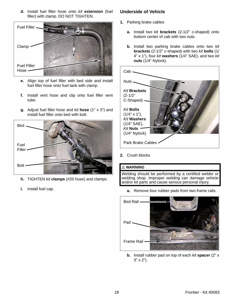
d. Install fuel filler hose onto kit extension (fuelfiller) with clamp. DO NOT TIGHTEN.
e. Align top of fuel filler with bed side and installfuel filler hose onto fuel tank with clamp.
f. Install vent hose and clip onto fuel filler venttube.
g. Adjust fuel filler hose and kit hose (1” x 3”) andinstall fuel filler onto bed with bolt.
h. TIGHTEN kit clamps (#20 hose) and clamps.
i. Install fuel cap.
Fuel Filler
Clamp
Fuel FillerHose
Bed
FuelFiller
Bolt
Underside of Vehicle
1. Parking brake cables
a. Install two kit brackets (2-1/2” c-shaped) ontobottom center of cab with two nuts.
b. Install two parking brake cables onto two kitbrackets (2-1/2” c-shaped) with two kit bolts (1/4” x 1”), four kit washers (1/4” SAE), and two kitnuts (1/4” Nylock).
2. Crush blocks
a. Remove four rubber pads from two frame rails.
b. Install rubber pad on top of each kit spacer (2” x3” x 2”).
WARNING
Welding should be performed by a certified welder orwelding shop. Improper welding can damage vehicleand/or kit parts and cause serious personal injury.
Nuts
Park Brake Cables
Kit Bolts(1/4” x 1”),Kit Washers(1/4” SAE),Kit Nuts(1/4” Nylock)
Cab
Kit Brackets(2-1/2”C-Shaped)
Bed Rail
Pad
Frame Rail
19 Frontier - Kit 40083
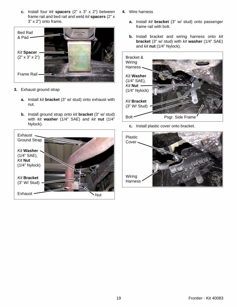
c. Install four kit spacers (2” x 3” x 2”) betweenframe rail and bed rail and weld kit spacers (2” x3” x 2”) onto frame.
3. Exhaust ground strap
a. Install kit bracket (3” w/ stud) onto exhaust withnut.
b. Install ground strap onto kit bracket (3” w/ stud)with kit washer (1/4” SAE) and kit nut (1/4”Nylock).
Bed Rail& Pad
Kit Spacer(2” x 3” x 2”)
Frame Rail
ExhaustGround Strap
Kit Washer(1/4” SAE),Kit Nut(1/4” Nylock)
Exhaust Nut
Kit Bracket(3” W/ Stud)
4. Wire harness
a. Install kit bracket (3” w/ stud) onto passengerframe rail with bolt.
b. Install bracket and wiring harness onto kitbracket (3” w/ stud) with kit washer (1/4” SAE)and kit nut (1/4” Nylock).
c. Install plastic cover onto bracket.
Bracket &WiringHarness
Kit Bracket(3” W/ Stud)
Psgr. Side Frame
Kit Washer(1/4” SAE),Kit Nut(1/4” Nylock)
Bolt
PlasticCover
WiringHarness
20 Frontier - Kit 40083
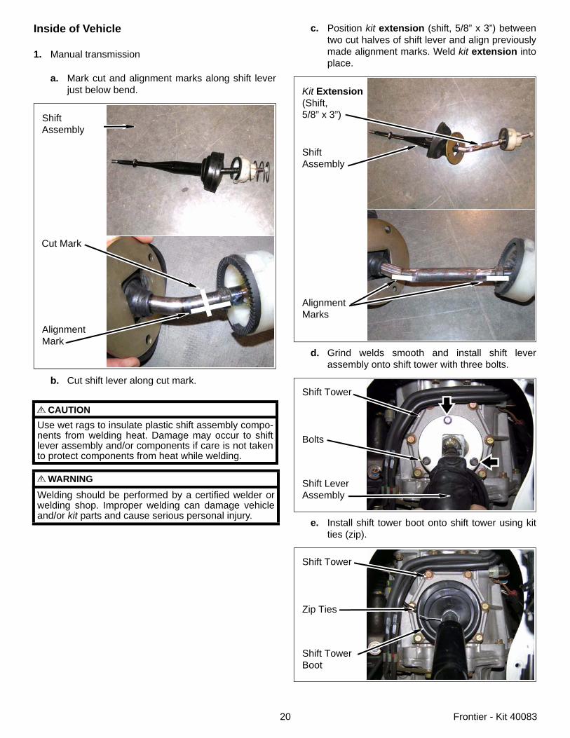
Inside of Vehicle
1. Manual transmission
a. Mark cut and alignment marks along shift leverjust below bend.
b. Cut shift lever along cut mark.
CAUTIONUse wet rags to insulate plastic shift assembly compo-nents from welding heat. Damage may occur to shiftlever assembly and/or components if care is not takento protect components from heat while welding.
WARNING
Welding should be performed by a certified welder orwelding shop. Improper welding can damage vehicleand/or kit parts and cause serious personal injury.
ShiftAssembly
Cut Mark
AlignmentMark
c. Position kit extension (shift, 5/8” x 3”) betweentwo cut halves of shift lever and align previouslymade alignment marks. Weld kit extension intoplace.
d. Grind welds smooth and install shift leverassembly onto shift tower with three bolts.
e. Install shift tower boot onto shift tower using kitties (zip).
Kit Extension(Shift,5/8” x 3”)
ShiftAssembly
AlignmentMarks
Shift Tower
Bolts
Shift LeverAssembly
Shift Tower
Zip Ties
Shift TowerBoot
21 Frontier - Kit 40083
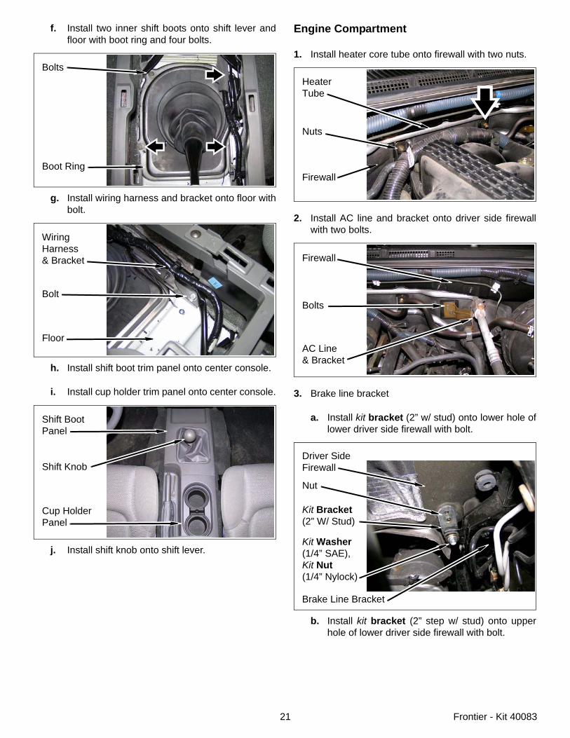
f. Install two inner shift boots onto shift lever andfloor with boot ring and four bolts.
g. Install wiring harness and bracket onto floor withbolt.
h. Install shift boot trim panel onto center console.
i. Install cup holder trim panel onto center console.
j. Install shift knob onto shift lever.
Bolts
Boot Ring
WiringHarness& Bracket
Bolt
Floor
Shift BootPanel
Shift Knob
Cup HolderPanel
Engine Compartment
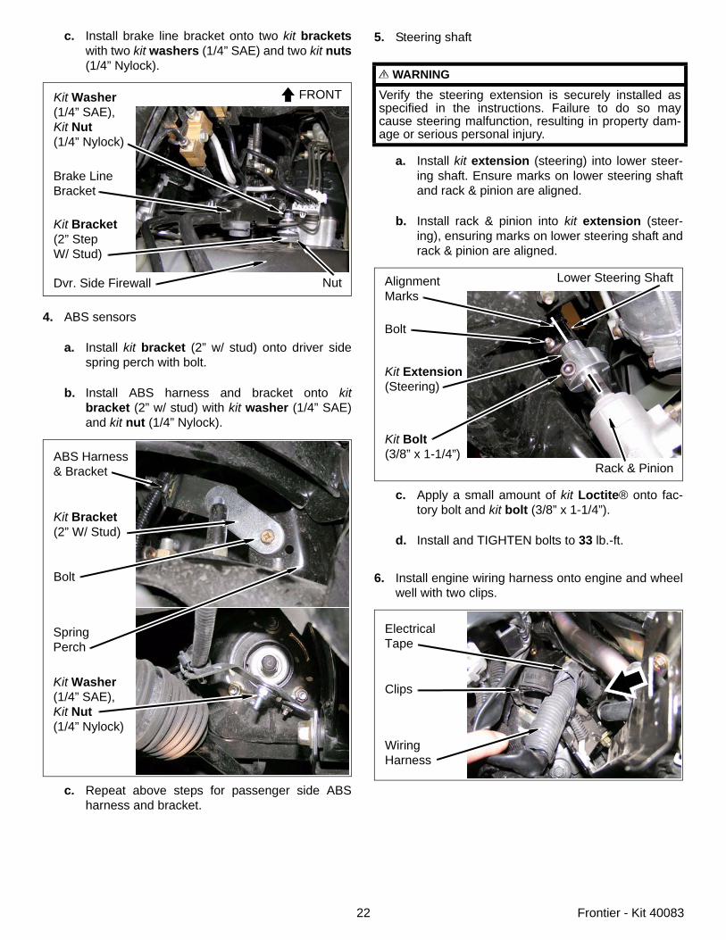
1. Install heater core tube onto firewall with two nuts.
2. Install AC line and bracket onto driver side firewallwith two bolts.
3. Brake line bracket
a. Install kit bracket (2” w/ stud) onto lower hole oflower driver side firewall with bolt.
b. Install kit bracket (2” step w/ stud) onto upperhole of lower driver side firewall with bolt.
Firewall
HeaterTube
Nuts
Firewall
Bolts
AC Line& Bracket
Driver SideFirewall
Nut
Kit Bracket(2” W/ Stud)
Brake Line Bracket
Kit Washer(1/4” SAE),Kit Nut(1/4” Nylock)
22 Frontier - Kit 40083
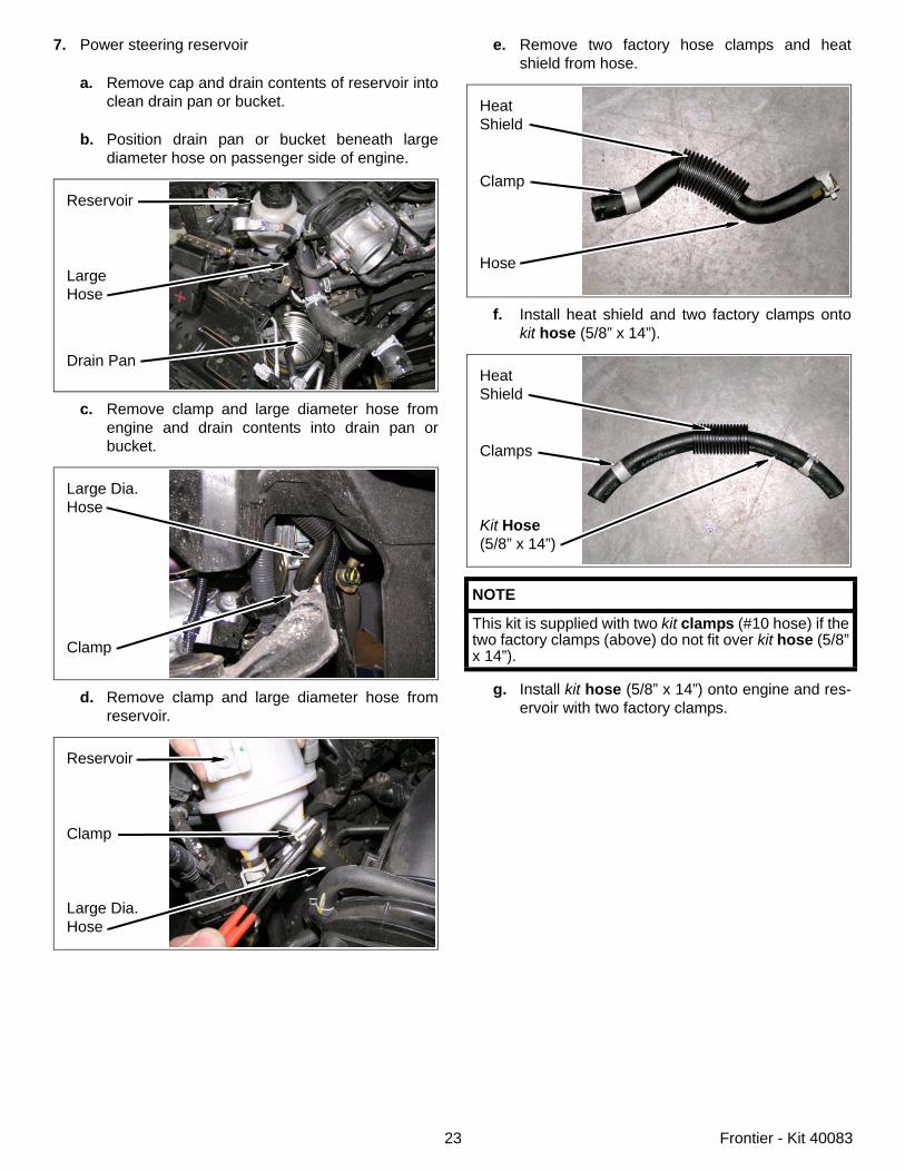
c. Install brake line bracket onto two kit bracketswith two kit washers (1/4” SAE) and two kit nuts(1/4” Nylock).
4. ABS sensors
a. Install kit bracket (2” w/ stud) onto driver sidespring perch with bolt.
b. Install ABS harness and bracket onto kitbracket (2” w/ stud) with kit washer (1/4” SAE)and kit nut (1/4” Nylock).
c. Repeat above steps for passenger side ABSharness and bracket.
Dvr. Side Firewall
Kit Bracket(2” StepW/ Stud)
Nut
Brake LineBracket
Kit Washer(1/4” SAE),Kit Nut(1/4” Nylock)
FRONT
ABS Harness& Bracket
Kit Bracket(2” W/ Stud)
Bolt
SpringPerch
Kit Washer(1/4” SAE),Kit Nut(1/4” Nylock)
5. Steering shaft
a. Install kit extension (steering) into lower steer-ing shaft. Ensure marks on lower steering shaftand rack & pinion are aligned.
b. Install rack & pinion into kit extension (steer-ing), ensuring marks on lower steering shaft andrack & pinion are aligned.
c. Apply a small amount of kit Loctite® onto fac-tory bolt and kit bolt (3/8” x 1-1/4”).
d. Install and TIGHTEN bolts to 33 lb.-ft.
6. Install engine wiring harness onto engine and wheelwell with two clips.
WARNING
Verify the steering extension is securely installed asspecified in the instructions. Failure to do so maycause steering malfunction, resulting in property dam-age or serious personal injury.
Kit Extension(Steering)
Kit Bolt(3/8” x 1-1/4”)
Rack & Pinion
Lower Steering ShaftAlignmentMarks
Bolt
ElectricalTape
Clips
WiringHarness
23 Frontier - Kit 40083
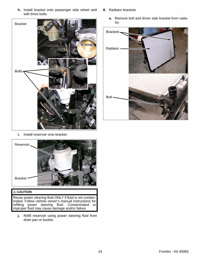
7. Power steering reservoir
a. Remove cap and drain contents of reservoir intoclean drain pan or bucket.
b. Position drain pan or bucket beneath largediameter hose on passenger side of engine.
c. Remove clamp and large diameter hose fromengine and drain contents into drain pan orbucket.
d. Remove clamp and large diameter hose fromreservoir.
Reservoir
LargeHose
Drain Pan
Large Dia.Hose
Clamp
Reservoir
Clamp
Large Dia.Hose
e. Remove two factory hose clamps and heatshield from hose.
f. Install heat shield and two factory clamps ontokit hose (5/8” x 14”).
g. Install kit hose (5/8” x 14”) onto engine and res-ervoir with two factory clamps.
NOTE
This kit is supplied with two kit clamps (#10 hose) if thetwo factory clamps (above) do not fit over kit hose (5/8”x 14”).
HeatShield
Clamp
Hose
HeatShield
Clamps
Kit Hose(5/8” x 14”)
24 Frontier - Kit 40083
h. Install bracket onto passenger side wheel wellwith three bolts.
i. Install reservoir onto bracket.
j. Refill reservoir using power steering fluid fromdrain pan or bucket.
CAUTION
Reuse power steering fluid ONLY if fluid is not contam-inated. Follow vehicle owner’s manual instructions forrefilling power steering fluid. Contaminated orimproper fluid may cause damage and/or failure.
Bracket
Bolts
Reservoir
Bracket
8. Radiator brackets
a. Remove bolt and driver side bracket from radia-tor.
Brackets
Radiator
Bolt
25 Frontier - Kit 40083
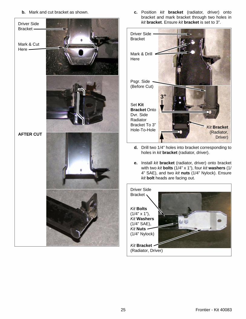
b. Mark and cut bracket as shown.
Driver SideBracket
Mark & CutHere
AFTER CUT
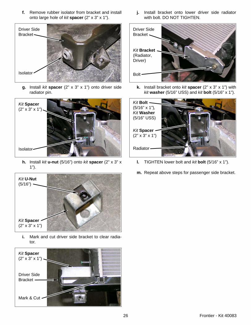
c. Position kit bracket (radiator, driver) ontobracket and mark bracket through two holes inkit bracket. Ensure kit bracket is set to 3”.
d. Drill two 1/4” holes into bracket corresponding toholes in kit bracket (radiator, driver).
e. Install kit bracket (radiator, driver) onto bracketwith two kit bolts (1/4” x 1”), four kit washers (1/4” SAE), and two kit nuts (1/4” Nylock). Ensurekit bolt heads are facing out.
Driver SideBracket
Mark & DrillHere
Psgr. Side(Before Cut)
3”
Kit Bracket(Radiator,
Driver)
Set KitBracket Onto Dvr. SideRadiator Bracket To 3” Hole-To-Hole
Driver SideBracket
Kit Bracket(Radiator, Driver)
Kit Bolts(1/4” x 1”),Kit Washers(1/4” SAE),Kit Nuts(1/4” Nylock)
26 Frontier - Kit 40083
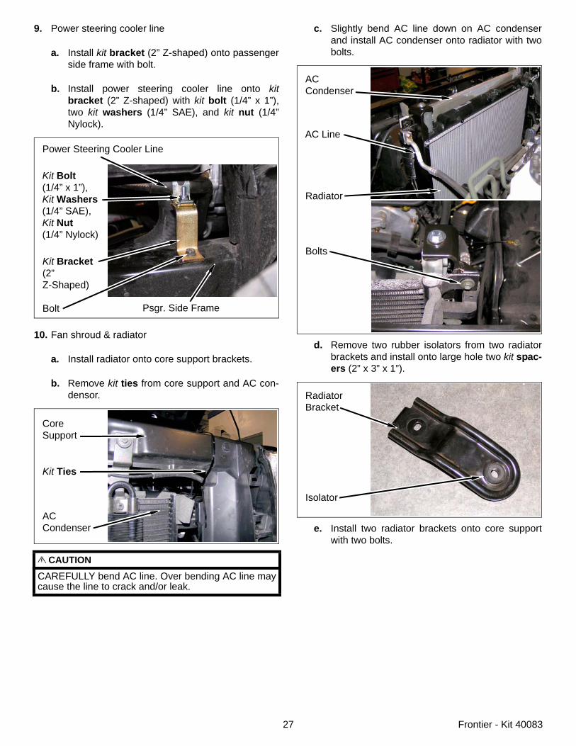
f. Remove rubber isolator from bracket and installonto large hole of kit spacer (2” x 3” x 1”).
g. Install kit spacer (2” x 3” x 1”) onto driver sideradiator pin.
h. Install kit u-nut (5/16”) onto kit spacer (2” x 3” x1”).
i. Mark and cut driver side bracket to clear radia-tor.
Driver SideBracket
Isolator
Kit Spacer(2” x 3” x 1”)
Isolator
Kit U-Nut(5/16”)
Kit Spacer(2” x 3” x 1”)
Driver SideBracket
Mark & Cut
Kit Spacer(2” x 3” x 1”)
j. Install bracket onto lower driver side radiatorwith bolt. DO NOT TIGHTEN.
k. Install bracket onto kit spacer (2” x 3” x 1”) withkit washer (5/16” USS) and kit bolt (5/16” x 1”).
l. TIGHTEN lower bolt and kit bolt (5/16” x 1”).
m. Repeat above steps for passenger side bracket.
Driver SideBracket
Kit Bracket(Radiator, Driver)
Bolt
Radiator
Kit Bolt(5/16” x 1”),Kit Washer(5/16” USS)
Kit Spacer(2” x 3” x 1”)
27 Frontier - Kit 40083
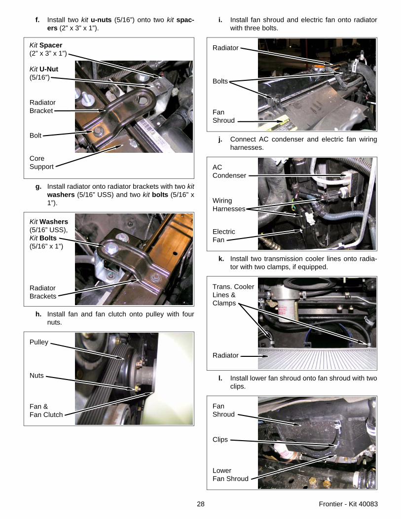
9. Power steering cooler line
a. Install kit bracket (2” Z-shaped) onto passengerside frame with bolt.
b. Install power steering cooler line onto kitbracket (2” Z-shaped) with kit bolt (1/4” x 1”),two kit washers (1/4” SAE), and kit nut (1/4”Nylock).
10. Fan shroud & radiator
a. Install radiator onto core support brackets.
b. Remove kit ties from core support and AC con-densor.
CAUTION
CAREFULLY bend AC line. Over bending AC line maycause the line to crack and/or leak.
Power Steering Cooler Line
Kit Bracket(2”Z-Shaped)
Bolt Psgr. Side Frame
Kit Bolt(1/4” x 1”),Kit Washers(1/4” SAE),Kit Nut(1/4” Nylock)
CoreSupport
Kit Ties
ACCondenser
c. Slightly bend AC line down on AC condenserand install AC condenser onto radiator with twobolts.
d. Remove two rubber isolators from two radiatorbrackets and install onto large hole two kit spac-ers (2” x 3” x 1”).
e. Install two radiator brackets onto core supportwith two bolts.
ACCondenser
Radiator
Bolts
AC Line
RadiatorBracket
Isolator
28 Frontier - Kit 40083
f. Install two kit u-nuts (5/16”) onto two kit spac-ers (2” x 3” x 1”).
g. Install radiator onto radiator brackets with two kitwashers (5/16” USS) and two kit bolts (5/16” x1”).
h. Install fan and fan clutch onto pulley with fournuts.
Kit U-Nut(5/16”)
RadiatorBracket
Bolt
Kit Spacer(2” x 3” x 1”)
CoreSupport
Kit Washers(5/16” USS),Kit Bolts(5/16” x 1”)
RadiatorBrackets
Pulley
Nuts
Fan &Fan Clutch
i. Install fan shroud and electric fan onto radiatorwith three bolts.
j. Connect AC condenser and electric fan wiringharnesses.
k. Install two transmission cooler lines onto radia-tor with two clamps, if equipped.
l. Install lower fan shroud onto fan shroud with twoclips.
Radiator
Bolts
FanShroud
ACCondenser
WiringHarnesses
ElectricFan
Trans. CoolerLines & Clamps
Radiator
FanShroud
Clips
LowerFan Shroud
29 Frontier - Kit 40083
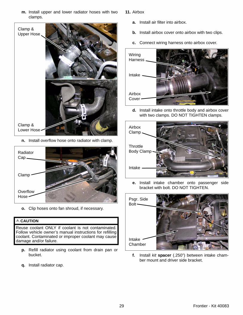
m. Install upper and lower radiator hoses with twoclamps.
n. Install overflow hose onto radiator with clamp.
o. Clip hoses onto fan shroud, if necessary.
p. Refill radiator using coolant from drain pan orbucket.
q. Install radiator cap.
CAUTION
Reuse coolant ONLY if coolant is not contaminated.Follow vehicle owner’s manual instructions for refillingcoolant. Contaminated or improper coolant may causedamage and/or failure.
Clamp &Upper Hose
Clamp &Lower Hose
RadiatorCap
Clamp
OverflowHose
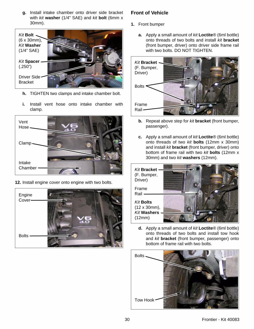
11. Airbox
a. Install air filter into airbox.
b. Install airbox cover onto airbox with two clips.
c. Connect wiring harness onto airbox cover.
d. Install intake onto throttle body and airbox coverwith two clamps. DO NOT TIGHTEN clamps.
e. Install intake chamber onto passenger sidebracket with bolt. DO NOT TIGHTEN.
f. Install kit spacer (.250”) between intake cham-ber mount and driver side bracket.
WiringHarness
Intake
AirboxCover
ThrottleBody Clamp
Intake
AirboxClamp
Psgr. SideBolt
IntakeChamber
30 Frontier - Kit 40083
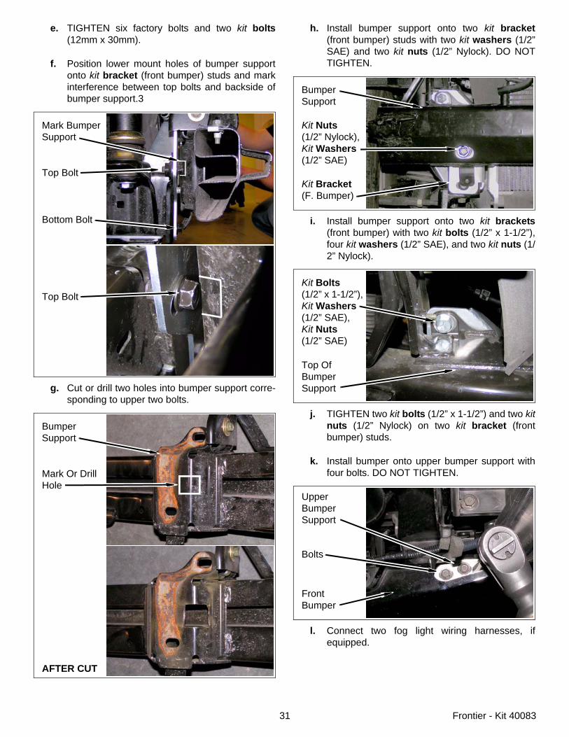
g. Install intake chamber onto driver side bracketwith kit washer (1/4” SAE) and kit bolt (6mm x30mm).
h. TIGHTEN two clamps and intake chamber bolt.
i. Install vent hose onto intake chamber withclamp.
12. Install engine cover onto engine with two bolts.
Kit Bolt(6 x 30mm),Kit Washer(1/4” SAE)
Kit Spacer(.250”)
Driver SideBracket
VentHose
Clamp
IntakeChamber
EngineCover
Bolts
Front of Vehicle
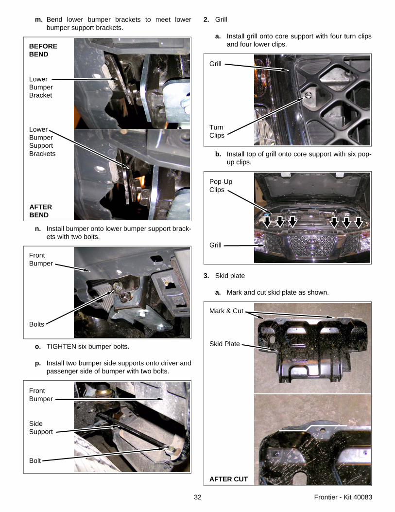
1. Front bumper
a. Apply a small amount of kit Loctite® (6ml bottle)onto threads of two bolts and install kit bracket(front bumper, driver) onto driver side frame railwith two bolts. DO NOT TIGHTEN.
b. Repeat above step for kit bracket (front bumper,passenger).
c. Apply a small amount of kit Loctite® (6ml bottle)onto threads of two kit bolts (12mm x 30mm)and install kit bracket (front bumper, driver) ontobottom of frame rail with two kit bolts (12mm x30mm) and two kit washers (12mm).
d. Apply a small amount of kit Loctite® (6ml bottle)onto threads of two bolts and install tow hookand kit bracket (front bumper, passenger) ontobottom of frame rail with two bolts.
Kit Bracket(F. Bumper,Driver)
Bolts
FrameRail
Kit Bolts(12 x 30mm),Kit Washers(12mm)
Kit Bracket(F. Bumper,Driver)
FrameRail
Bolts
Tow Hook
31 Frontier - Kit 40083
e. TIGHTEN six factory bolts and two kit bolts(12mm x 30mm).
f. Position lower mount holes of bumper supportonto kit bracket (front bumper) studs and markinterference between top bolts and backside ofbumper support.3
g. Cut or drill two holes into bumper support corre-sponding to upper two bolts.
Mark BumperSupport
Top Bolt
Bottom Bolt
Top Bolt
BumperSupport
Mark Or DrillHole
AFTER CUT
h. Install bumper support onto two kit bracket(front bumper) studs with two kit washers (1/2”SAE) and two kit nuts (1/2” Nylock). DO NOTTIGHTEN.
i. Install bumper support onto two kit brackets(front bumper) with two kit bolts (1/2” x 1-1/2”),four kit washers (1/2” SAE), and two kit nuts (1/2” Nylock).
j. TIGHTEN two kit bolts (1/2” x 1-1/2”) and two kitnuts (1/2” Nylock) on two kit bracket (frontbumper) studs.
k. Install bumper onto upper bumper support withfour bolts. DO NOT TIGHTEN.
l. Connect two fog light wiring harnesses, ifequipped.
BumperSupport
Kit Nuts(1/2” Nylock),Kit Washers(1/2” SAE)
Kit Bracket(F. Bumper)
Kit Bolts(1/2” x 1-1/2”),Kit Washers(1/2” SAE),Kit Nuts(1/2” SAE)
Top OfBumperSupport
Bolts
FrontBumper
Upper BumperSupport
32 Frontier - Kit 40083
m. Bend lower bumper brackets to meet lowerbumper support brackets.
n. Install bumper onto lower bumper support brack-ets with two bolts.
o. TIGHTEN six bumper bolts.
p. Install two bumper side supports onto driver andpassenger side of bumper with two bolts.
BEFOREBEND
LowerBumperBracket
LowerBumperSupportBrackets
AFTERBEND
FrontBumper
Bolts
FrontBumper
SideSupport
Bolt
2. Grill
a. Install grill onto core support with four turn clipsand four lower clips.
b. Install top of grill onto core support with six pop-up clips.
3. Skid plate
a. Mark and cut skid plate as shown.
Grill
TurnClips
Pop-UpClips
Grill
Mark & Cut
Skid Plate
AFTER CUT
33 Frontier - Kit 40083
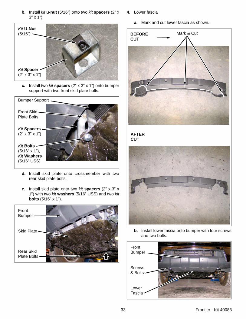
b. Install kit u-nut (5/16”) onto two kit spacers (2” x3” x 1”).
c. Install two kit spacers (2” x 3” x 1”) onto bumpersupport with two front skid plate bolts.
d. Install skid plate onto crossmember with tworear skid plate bolts.
e. Install skid plate onto two kit spacers (2” x 3” x1”) with two kit washers (5/16” USS) and two kitbolts (5/16” x 1”).
Kit U-Nut(5/16”)
Kit Spacer(2” x 3” x 1”)
Front SkidPlate Bolts
Kit Bolts(5/16” x 1”),Kit Washers(5/16” USS)
Kit Spacers(2” x 3” x 1”)
Bumper Support
FrontBumper
Skid Plate
Rear SkidPlate Bolts
4. Lower fascia
a. Mark and cut lower fascia as shown.
b. Install lower fascia onto bumper with four screwsand two bolts.
Mark & CutBEFORECUT
AFTERCUT
FrontBumper
Screws& Bolts
LowerFascia
34 Frontier - Kit 40083
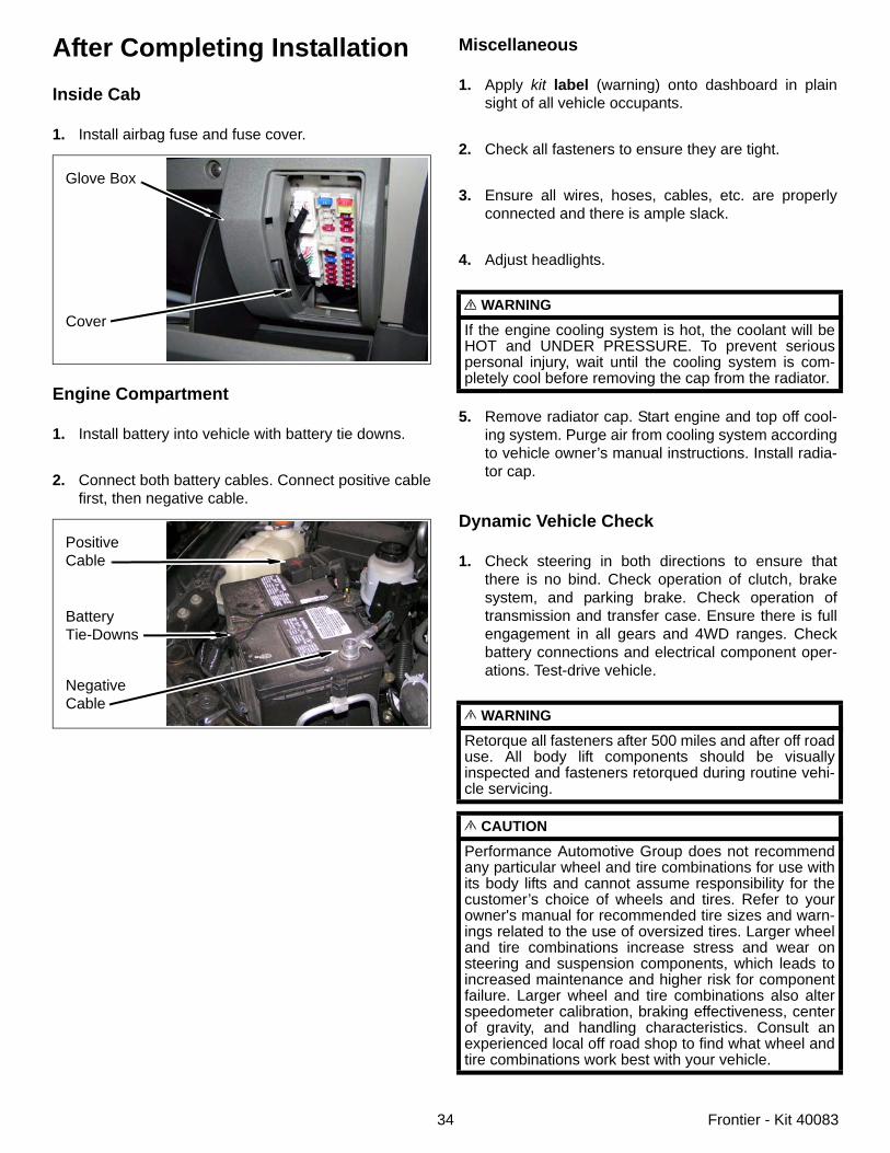
After Completing InstallationInside Cab
1. Install airbag fuse and fuse cover.
Engine Compartment
1. Install battery into vehicle with battery tie downs.
2. Connect both battery cables. Connect positive cablefirst, then negative cable.
Glove Box
Cover
PositiveCable
BatteryTie-Downs
NegativeCable
Miscellaneous
1. Apply kit label (warning) onto dashboard in plainsight of all vehicle occupants.
2. Check all fasteners to ensure they are tight.
3. Ensure all wires, hoses, cables, etc. are properlyconnected and there is ample slack.
4. Adjust headlights.
5. Remove radiator cap. Start engine and top off cool-ing system. Purge air from cooling system accordingto vehicle owner’s manual instructions. Install radia-tor cap.
Dynamic Vehicle Check
1. Check steering in both directions to ensure thatthere is no bind. Check operation of clutch, brakesystem, and parking brake. Check operation oftransmission and transfer case. Ensure there is fullengagement in all gears and 4WD ranges. Checkbattery connections and electrical component oper-ations. Test-drive vehicle.
WARNING
If the engine cooling system is hot, the coolant will beHOT and UNDER PRESSURE. To prevent seriouspersonal injury, wait until the cooling system is com-pletely cool before removing the cap from the radiator.
WARNING
Retorque all fasteners after 500 miles and after off roaduse. All body lift components should be visuallyinspected and fasteners retorqued during routine vehi-cle servicing.
CAUTION
Performance Automotive Group does not recommendany particular wheel and tire combinations for use withits body lifts and cannot assume responsibility for thecustomer’s choice of wheels and tires. Refer to yourowner's manual for recommended tire sizes and warn-ings related to the use of oversized tires. Larger wheeland tire combinations increase stress and wear onsteering and suspension components, which leads toincreased maintenance and higher risk for componentfailure. Larger wheel and tire combinations also alterspeedometer calibration, braking effectiveness, centerof gravity, and handling characteristics. Consult anexperienced local off road shop to find what wheel andtire combinations work best with your vehicle.
35 Frontier - Kit 40083
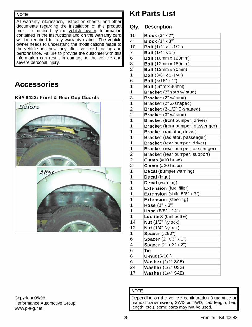
AccessoriesKit# 6423: Front & Rear Gap Guards
NOTE
All warranty information, instruction sheets, and otherdocuments regarding the installation of this productmust be retained by the vehicle owner. Informationcontained in the instructions and on the warranty cardwill be required for any warranty claims. The vehicleowner needs to understand the modifications made tothe vehicle and how they affect vehicle handling andperformance. Failure to provide the customer with thisinformation can result in damage to the vehicle andsevere personal injury.
Kit Parts ListQty. Description
NOTE
Depending on the vehicle configuration (automatic ormanual transmission, 2WD or 4WD, cab length, bedlength, etc.), some parts may not be used.
10 Block (3" x 2")4 Block (3" x 3")10 Bolt (1/2" x 1-1/2")7 Bolt (1/4" x 1")6 Bolt (10mm x 120mm)8 Bolt (12mm x 180mm)2 Bolt (12mm x 30mm)1 Bolt (3/8" x 1-1/4")6 Bolt (5/16" x 1")1 Bolt (6mm x 30mm)1 Bracket (2" step w/ stud)3 Bracket (2" w/ stud)1 Bracket (2" Z-shaped)2 Bracket (2-1/2" C-shaped)2 Bracket (3" w/ stud)1 Bracket (front bumper, driver)1 Bracket (front bumper, passenger)1 Bracket (radiator, driver)1 Bracket (radiator, passenger)1 Bracket (rear bumper, driver)1 Bracket (rear bumper, passenger)2 Bracket (rear bumper, support)2 Clamp (#10 hose)2 Clamp (#20 hose)1 Decal (bumper warning)1 Decal (logo)1 Decal (warning)1 Extension (fuel filler)1 Extension (shift, 5/8" x 3")1 Extension (steering)1 Hose (1" x 3")1 Hose (5/8" x 14")1 Loctite® (6ml bottle)14 Nut (1/2" Nylock)12 Nut (1/4" Nylock)1 Spacer (.250")6 Spacer (2" x 3" x 1")4 Spacer (2" x 3" x 2")6 Tie6 U-nut (5/16")6 Washer (1/2" SAE)24 Washer (1/2" USS)17 Washer (1/4" SAE)
Copyright 05/06Performance Automotive Groupwww.p-a-g.net