nitrogen fixation,' in: ullmann's encyclopedia of...
TRANSCRIPT

Nitrogen Fixation
BHASKAR S. PATIL,Micro Flow Chemistry and Process Technology, EindhovenUniversity of Technology, Eindhoven, The Netherlands
VOLKER HESSEL,Micro Flow Chemistry and Process Technology, EindhovenUniversity of Technology, Eindhoven, The Netherlands
LANCE C. SEEFELDT, Department of Chemistry and Biochemistry, Utah State University,Logan, UT, United States
DENNIS R. DEAN, Department of Biochemistry, Virginia Polytechnic Institute and StateUniversity, Blacksburg, VA, United States
BRIAN M. HOFFMAN, Department of Chemistry, Northwestern University, Evanston, IL,United States
BRIAN J. COOK, Center for Catalysis & Center for Heterocyclic Compounds,Department of Chemistry, University of Florida, Gainesville, Florida, United States
LESLIE J. MURRAY, Center for Catalysis & Center for Heterocyclic Compounds,Department of Chemistry, University of Florida, Gainesville, Florida, United States
1. Introduction . . . . . . . . . . . . . . . . . 12. Biological Nitrogen Fixation . . . . . . 22.1. Nitrogenases . . . . . . . . . . . . . . . . . 22.1.1. Mo-Nitrogenase . . . . . . . . . . . . . . . 32.1.2. Fe Protein Cycle . . . . . . . . . . . . . . . 32.1.3. MoFe Protein Cycle . . . . . . . . . . . . 43. Chemical Nitrogen Fixation . . . . . . 63.1. Industrial Processes for Nitrogen
Fixation . . . . . . . . . . . . . . . . . . . . 73.1.1. Plasma Assisted Nitrogen Fixation:
Birkeland–Eyde Arc Process. . . . . . . 73.1.2. Frank and Caro Cyanamide Process. . 9
3.1.3. Haber–Bosch Process (HBP): ACentury of Heterogeneous AmmoniaCatalysis . . . . . . . . . . . . . . . . . . . . 9
3.2. Lab-Scale Efforts for ChemicalNitrogen Fixation . . . . . . . . . . . . . 10
3.2.1. Electrocatalytic Nitrogen Fixation . . . 113.2.2. Photocatalytic Nitrogen Fixation . . . . 123.2.3. Homogeneous Catalytic Nitrogen
Reduction to Ammonia . . . . . . . . . . 123.2.4. Nonthermal Plasma (NTP) Assisted
Nitrogen Fixation . . . . . . . . . . . . . . 15References. . . . . . . . . . . . . . . . . . . 16
1. Introduction
Nitrogen (dinitrogen or N2), which makes up to∼78.08% of the Earth’s atmosphere, is an essen-tial element for sustaining all living organisms[1]. Nitrogen is found in nucleic acids, chloro-phyll, and amino acids, to name a few biologicalconstituents [2]. Even though dinitrogen isabundantly available, it is not directly accessibleto plants and animals. Dinitrogen can only beused in its “fixed” form, like ammonium NH4
� �
and nitrate NO3� �
. To become metabolicallyavailable, the NºN triple bond must be broken,and the resulting atomic nitrogen must be chem-ically bonded with other elements, such asoxygen and/or hydrogen through a process
called “nitrogen fixation” [3]. Atomic nitrogencan also be combined with carbon throughprocess known as “nitrogen assimilation” [3].Some prokaryotes are capable of directly fixingatmospheric dinitrogen and supplying it toplants in a process known as biological nitrogenfixation [4, 5], through which almost half of N2
is fixed on Earth. Biological fixation of dini-trogen takes places in the ocean and waterbodies, during farming, and in forest and non-agricultural land. The other important naturalsources for fixed nitrogen, which is nonbiolog-ical, are lightning that result from the electricdischarge between two clouds and combustionprocesses, where conditions are optimum forNOx formation [6]. The increasing food demand
2017 Wiley-VCH Verlag GmbH & Co. KGaA, Weinheim10.1002/14356007.a17_471.pub2

from the exploding global population necessi-tated intensified agricultural practices, whichmeant that biologically fixed nitrogen was nolonger sufficient and thus, chemical processes toartificially fix nitrogen were developed [7–9].Today almost all chemically fixed nitrogencomes from the Haber–Bosch process (dis-cussed in Section 3.1.3) [10]. The estimationof global nitrogen fixation quantities, asreported in 2010, are shown in Figure 1 [6].In this figure, the segments farming, ocean, andforest represent nitrogen fixation by nitrogenasein microorganisms present in those locales.
Besides using fixed nitrogen as a fertilizer inagriculture, chemically fixed nitrogen in the
form of ammonia is also used for large scaleapplications in chemical industry, e.g., pharma-ceuticals, explosives, and plastic manufacturing[9, 11] (See also → Ammonia, 2. ProductionProcesses). A complete picture of the range ofproducts derived from ammonia is presented inFigure 2.
The chemical process for nitrogen fixation isnotorious for high CO2 emission, energy con-sumption, and harsh operating conditions. Onthe other hand, biological nitrogen fixation takesplace at mild conditions, thus it gives hope fordevelopment of a new artificial nitrogen fixationprocess operating under mild operating condi-tions [9, 12]. This possibility has opened doorsfor different research areas in biological andchemical nitrogen fixation and have been thesubject of increasing efforts since 1960s.
Various approaches and key conceptsinvolved in biological and chemical nitrogenfixation processes are briefly discussed as wellas some commercially applied chemical pro-cesses for nitrogen fixation.
2. Biological Nitrogen Fixation
2.1. Nitrogenases
More than half of the N2 fixed on Earth isaccomplished by microorganisms through the
Figure 1. Estimation of quantities of fixed nitrogen in 106 t/ain 2010 [6]; the farming, ocean, and forest segments alldenote nitrogen fixation by nitrogenase in microorganismspresent in those locales, adapted from [9] with kindpermission of Elsevier B.V.
Figure 2. Range of applications of chemically fixed nitrogen in the form of ammonia, reprinted from [9]with kind permissionof Elsevier B.V.
2 Nitrogen Fixation

action of the enzyme nitrogenase [10]. Nitroge-nases are found in two of the three domains oflife, i.e., in bacteria and archaea [13–16]. Nitro-genases are found in a wide-array of thesemicrobes, which are often referred to as diazo-trophs. Nitrogenases have not been found in anyeukaryotes. Diazatrophs are found in most eco-systems, including aquatic (e.g., oceans) andterrestrial [16]. Three different nitrogenaseshave been identified, with some microbes con-taining all three. The most commonly foundand best studied nitrogenase is called Mo-nitrogenase, reflecting the presence of theelement molybdenumMo as part of the complexmetal cluster that forms the site of N2 bindingand reduction [17]. The other two nitrogenasetypes are often referred to as “alternative” nitro-genases, because they are not as often found andnot as well studied [18]. These alternative nitro-genases are called V-nitrogenase and Fe-onlynitrogenase, with the names reflecting thereplacement of Mo by the metals vanadiumand iron, in the active site metal cluster, respec-tively. The alternative nitrogenases are codedfor by unique gene clusters, so are distinctenzymes. However, the overall architecture ofthe protein complexes and metal clusters appearto be very similar to the Mo-nitrogenase. Forthis reason, and especially because of the prev-alence of the Mo-nitrogenase, this enzyme istaken as the paradigm for nitrogenases and isthe focus of this presentation. Reviews on thealternative nitrogenases can be found elsewhere[18, 19].
2.1.1. Mo-Nitrogenase
The Mo-nitrogenase is composed of two proteincomplexes, referred to as MoFe protein (alsocalled dinitrogenase or component I) and Feprotein (also referred to as dinitrogenase reduc-tase or component II) [17]. The MoFe protein isan α2β2 heterotetramer, with each αβ dimerconstituting a minimal catalytic unit [20, 21].Each αβ dimer contains an 8Fe-7S cluster calledP cluster and an 7Fe-9S-Mo-C-homocitratecluster called FeMo-cofactor [22]. The FeMo-cofactor (also termed FeMo-co) is the site ofsubstrate binding and reduction [23]. The Pcluster is proposed to serve as an electronshuttle, delivering electrons to FeMo-co [24].The Fe protein component is an α2 homodimer,
having a single 4Fe-4S cluster that bridges thetwo subunits [25]. Each subunit of the Fe pro-tein contains an ATP binding site. During catal-ysis, the Fe protein transiently associates withthe MoFe protein, during which an electron istransferred from the Fe protein to the MoFeprotein and the two ATP molecules are hydro-lyzed to two ADP and two inorganic phosphate(Pi) [26]. The complete catalytic cycle of nitro-genase involves a number of steps in eachprotein component. The steps in each proteincomponent are intertwined; for convenience theevents associated with the Fe protein delivery ofelectrons are often called the Fe protein cycle,whereas the events associated with the MoFeprotein are called the MoFe protein cycle. Keysteps in each of these cycles are summarized inFigure 3.
2.1.2. Fe Protein Cycle
The Fe protein functions to deliver electrons tothe MoFe protein during the transient associa-tion of the two proteins [27]. The Fe proteincycle is initiated when the Fe protein, with areduced [4Fe-4S]1+ cluster and two bound ATP,associates with one αβ unit of the MoFe protein.A series of X-ray structures of Fe protein dockedto the MoFe protein have shown that the Feprotein binds to the surface of the MoFe proteindirectly over a P cluster [28–30]. Kinetic studiesshow the association of the Fe protein with theMoFe protein to be fast relative to other keysteps [26]. Following association of the Fe
Figure 3. A) Schematic representation of the MoFe proteinand Fe protein components of nitrogenase; only one half ofthe MoFe protein is shown with a symmetrical αβ half notshown. The Fe protein contains one 4Fe-4S cluster and twoATP binding sites. Each αβ half of the MoFe proteincontains an 8Fe-7S cluster (called the P cluster) and aFeMo-cofactor (called FeMo-co or M cluster); B) Structuresof the metal clusters; Fe is shown in rust, S in yellow, C ingrey, O in red, and Mo in magenta
Nitrogen Fixation 3

protein with the MoFe protein, a sequence ofsteps happens rapidly (Fig. 4). A pre-steadystate study revealed that electron transfer (ET)from the Fe protein to the MoFe protein is thefirst step after protein association, with a pseudofirst order rate constant of 140 s�1 [31]. Thiselectron transfer event has been shown to beconformationally gated, with large scale proteinchanges in the structure of the complex preced-ing and controlling electron transfer [32]. Theinvolvement of the P cluster in the ET events hasbeen established [24], with available evidencesuggesting a deficit spending order of ET steps[32]. Following protein–protein association, theP cluster transfers one electron to the FeMo-coin a gated step, which is followed by fast ETfrom the Fe protein to the oxidized P cluster.The net result of the ET events is oxidation ofthe reduced Fe protein and the transfer of anelectron to FeMo-cofactor. This ET process inthe Fe protein cycle is followed by ATP hydrol-ysis with a first order rate constant of about 40s�1 [31, 33]. This step is then followed by Pirelease with a rate constant of about 20 s�1.Finally, the oxidized Fe protein, presumablywith two bound ADP, dissociates from theMoFe protein. Earlier studies using the non-physiological reductant dithionite as the elec-tron source for the reduction of Fe proteinsuggested that this dissociation step had a rateconstant of 6 s�1 and thus was the rate-limitingstep [26]. However, a study from 2016 usingreduced flavodoxin, one of the natural reduc-tants in the cell, revealed that the dissociationstep was fast with this reductant, indicating thatevents associated with the Pi release step are
rate-limiting for the Fe protein cycle [34]. Oncedissociated, the Fe protein is reduced (physio-logically by flavodoxin or ferredoxin) and theADP is replaced by ATP to recharge the Feprotein and complete the Fe protein cycle.
2.1.3. MoFe Protein Cycle
Electrons received by theMoFe protein from theFe protein are ultimately accumulated on FeMo-cofactor. A kinetic scheme representing theaccumulation of electrons into the MoFe proteinwas put forward by LOWE and THORNELEY [26]from a series of kinetic and spectroscopic stud-ies. In a modified and simplified Lowe andThorneley (LT) scheme, the E0 state representsthe resting state before any electrons are accu-mulated, with the number of electrons trans-ferred to MoFe protein indicated with an nsubscript (En) as shown in Figure 5. Since theelectrons are ultimately accumulated on FeMo-cofactor, the En state can be taken as the number
Figure 4. Schematic presentation of the Fe protein cycle. One αβ unit of the MoFe protein is shown on top containing a Pcluster (P) and FeMo-cofactor in the resting (M) or one electron reduced (Mr) state. The α2 dimer Fe protein is shown on thebottom with a 4Fe-4S cluster (box) in the reduced (R) or oxidized (ox) state. The rate constants for each step are shown.
Figure 5. Simplified Lowe and Thorneley scheme. E rep-resents the MoFe protein that has accumulated n electronsfrom the Fe protein cycle.
4 Nitrogen Fixation
of electrons accumulated in FeMo-cofactor orone of its bound, semireduced intermediates.Each electron accumulated on FeMo-cofactor islikely balanced by the accumulation of a proton,in proton coupled electron transfer. The accu-mulated protons also are indicated in the schemeof Figure 5. Several aspects of this kineticscheme are noteworthy. First, the E2(2H),E3(3H), and E4(4H) states can “relax” by for-mation of H2 back to lower E states. This reflectsthe long-known fact that nitrogenase can evolveH2 in the absence of any other substrate [35]. Itwas also established from early kinetic studiesthat N2 does not bind until at least three or fourelectrons/protons are accumulated on FeMo-cofactor (shown binding to the E4 state inFig. 5) [26]. The mechanistic reason for theneed to accumulate four electrons/protons onFeMo-cofactor before N2 can bind remained amystery for decades. Even more so, the incor-poration of a stoichiometric release of one H2
for each N2 bound, with a resulting stoichio-metric requirement of 8 e�/H+ to form twoNH3, remained a mystery, and indeed was noteven universally accepted [17]. Studies of themid-2000s have validated this stoichiometryand revealed the mechanistic reason for thesephenomenon [36–38].
A key breakthrough in understanding themechanism of N2 binding came from the trap-ping of a catalytically central intermediate usinga combination of substitution of amino acidsnear the active site and freeze quenching sam-ples during turnover [39–49]. Spectroscopic andkinetic examination of the trapped state usingFeMo-cofactor 57Fe, 95Mo, 1H, and 2H iso-topomers led to two important conclusionsabout this intermediate: (i) The state isE4(4H), which has accumulated 4[e�/H+] andis activated to bind N2 for reduction with H2
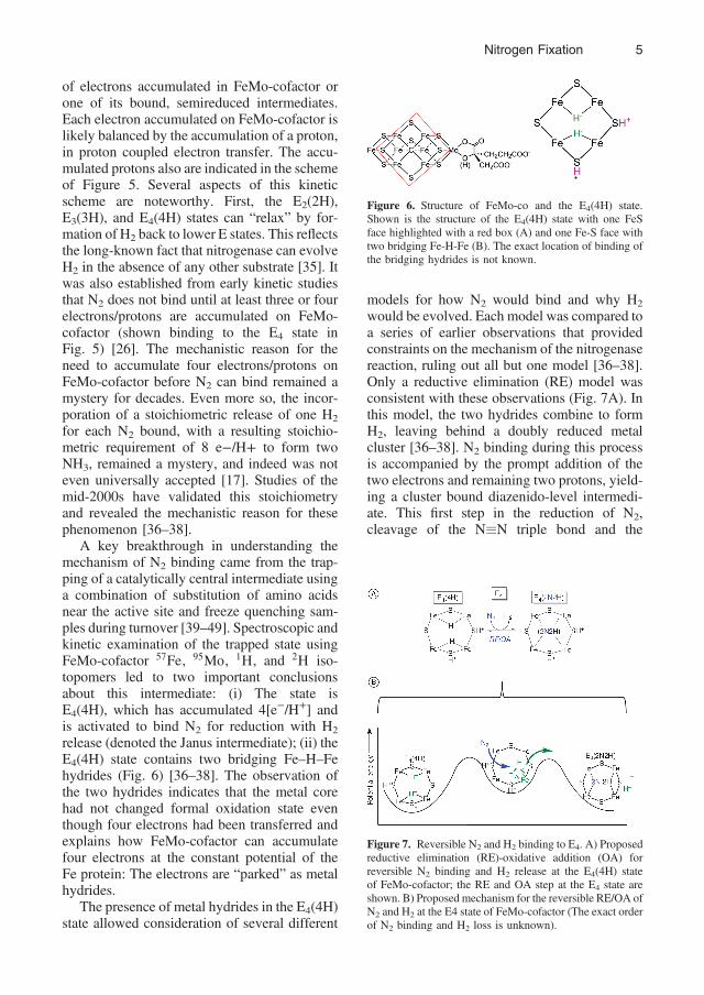
release (denoted the Janus intermediate); (ii) theE4(4H) state contains two bridging Fe–H–Fehydrides (Fig. 6) [36–38]. The observation ofthe two hydrides indicates that the metal corehad not changed formal oxidation state eventhough four electrons had been transferred andexplains how FeMo-cofactor can accumulatefour electrons at the constant potential of theFe protein: The electrons are “parked” as metalhydrides.
The presence of metal hydrides in the E4(4H)state allowed consideration of several different
models for how N2 would bind and why H2
would be evolved. Each model was compared toa series of earlier observations that providedconstraints on the mechanism of the nitrogenasereaction, ruling out all but one model [36–38].Only a reductive elimination (RE) model wasconsistent with these observations (Fig. 7A). Inthis model, the two hydrides combine to formH2, leaving behind a doubly reduced metalcluster [36–38]. N2 binding during this processis accompanied by the prompt addition of thetwo electrons and remaining two protons, yield-ing a cluster bound diazenido-level intermedi-ate. This first step in the reduction of N2,cleavage of the NºN triple bond and the
Figure 6. Structure of FeMo-co and the E4(4H) state.Shown is the structure of the E4(4H) state with one FeSface highlighted with a red box (A) and one Fe-S face withtwo bridging Fe-H-Fe (B). The exact location of binding ofthe bridging hydrides is not known.
Figure 7. Reversible N2 and H2 binding to E4. A) Proposedreductive elimination (RE)-oxidative addition (OA) forreversible N2 binding and H2 release at the E4(4H) stateof FeMo-cofactor; the RE and OA step at the E4 state areshown. B) Proposed mechanism for the reversible RE/OA ofN2 and H2 at the E4 state of FeMo-cofactor (The exact orderof N2 binding and H2 loss is unknown).
Nitrogen Fixation 5

2 e�/H+ conversion to a cluster bound diaze-nido-intermediate, is by far the thermo-dynamically most difficult step of N2 fixationand is thermodynamically driven by the reduc-tion of two protons and hydrolysis of four ATP,which leads to H2 release [36]. Studies of thenative MoFe show that the Janus intermediate inthe modified and native MoFe are identical andthat the process in Figure 7A is indeed a kineti-cally reversible and essentially thermoneutralequilibrium, driving the cleavage of the NºNtriple bond, whereas direct reduction of N2 todiazene is extremely endergonic [47–49]. Sub-sequent addition of protons and electrons ulti-mately lead to the formation of two ammonia(NH3) molecules. There are two alternatives asto when the first NH3 is released, after deliveryof 5 e�/H+ to FeMo-cofactor, or after 7 e�/H+,with the preponderance of the evidence favoringthe latter [36, 50, 51].
If N2 binding and reduction truly involvesRE and is a readily reversible equilibrium, thenin the presence of added H2 the equilibrium canbe reversed, with oxidative addition (OA) of H2
to E4(2N2H) generating the bridging hydridesand releasing N2 to form the E4(4H) state. Sucha reaction would explain the observation thatdeuterium (D2) is converted to two HD whennitrogenase is turned over under D2 and N2 [17,52, 53]. In this case, the D2 undergoes OA toload two Fe–D–Fe bridging deuterides [36].These deuterides, not being exchangeablewith solvent, can be protonated by the sulfur-bound protons derived from solvent, yieldingtwo HD, corresponding to the relaxation steps ofFigure 3. This proposed explanation for the HDformation associated with the RE mechanismfor N2 activation was tested and confirmed bythe demonstration that when the known sub-strate acetylene (C2H2) was added along withN2 and D2, the acetylene intercepted the [Fe–D–Fe]-containing states, resulting in the reductionof acetylene to ethylenes with one or two D(C2DH3 and C2D2H2) [44]. In the absence of N2,deutero-acetylenes are not formed, because thebridging deuterides only form through RE/OAat the E4(4H) state.
The photolysis of transition metal dihydridecomplexes commonly results in the reductiveelimination of H2 [54], and it has beenobserved that cryogenic irradiation of nitroge-nase E4(4H) with visible light likewise results
in the photoinduced RE of a H2 [46–49]. Whenthe photolyzed sample was warmed to 217 K,the process was reversed, with OA of thereleased H2 to reform the E4(4H) state. Kineticanalysis of the rates of loss of the E4(4H) stateand the formation of the E4(2H)
∗ state haveuncovered the existence of an intermediatebetween these two state, which has beenassigned to a H2 bound state (Fig. 7) [49].The analysis further suggested that this H2
functions as an intermediate in the thermalRE of H2 that activates FeMo-co to breakthe NºN triple bond during catalysis. Whilethe order of H2 release and N2 binding has notbeen experimentally established, it is neces-sary that N2 bind before H2 is released. Loss ofH2 first essentially results in an E2(2H) state,which is not expected to bind N2. This suggeststhat N2 would at least associate with the H2
bound state (Fig. 7).With these studies, the central elements of
the nitrogenase mechanism have becomeclear. Similar studies are needed to fill outthe full reaction pathway for N2 reduction.This includes a deepened understanding ofhow electrons/protons are accumulated in theearly E states and how the FeMo-co bounddiazene is stepwise reduced to two ammoniamolecules.
Many challenges remain to fully understandhow nitrogenase catalyzes the reduction of N2 toammonia under mild conditions, but extensivestudies since the 1960s have disclosed manyaspects of this fascinating and complex molec-ular machine, while studies since 2007 revealthe heart of its catalytic mechanism.
3. Chemical Nitrogen Fixation
The NºN triple bond is one of the strongest,which needs 9.77 eV (941 kJ/mol) of energy todissociate and has an ionization potential of 15.6eV [55]. This indicates the extremely highenergy required for cleaving or oxidation ofthe dinitrogen molecule. Moreover, dinitrogencan only be reduced by highly electropositivemetals, such as lithium (with electronegativityof 0.98). Thus, breaking the NºN triple bond isoften the rate-limiting step in the nitrogen fixa-tion process and is the subject of considerableresearch [12].
6 Nitrogen Fixation

3.1. Industrial Processes for NitrogenFixation
Up to the beginning of the 19th century, thefixed nitrogen stockpiled in the form of organicor inorganic materials over millions of yearswas enough to sustain the demands of theEarth’s population [9]. An explosive growthof population, with increasing sizes of cities,demanded ways to provide more nitrogenthrough nitrogen fixation. Starting early in the20th century, nitrogen obtained from artificialprocesses overtook the nitrogen obtained fromnatural organic and inorganic sources [56]. Thechemical nitrogen fixation processes could onlybe developed on industrial scale, includingreactions for the production of nitric oxide(NO), ammonia (NH3), hydrogen cyanide(HCN) and nitric acid (HNO3); all these effortscould be combined into the following threemain approaches with the corresponding indus-trial process as an example:
∙ Combining atmospheric nitrogen and oxy-gen to form nitric oxide: e.g., Birkeland–Eyde electric arc process [57, 58]
∙ Use of compounds capable of fixing nitro-gen in their structure: e.g., cyanamide(Frank-Caro) process [56, 59, 60]
∙ Combining atmospheric nitrogen withhydrogen to form ammonia: e.g.,Haber–Bosch process [61] (→ Ammonia,2. Production Processes)
These processes are discussed below.Figure 8 outlines the most significant eventsin the industrialized nitrogen fixation processdevelopment [56, 62, 63].
Both, Birkeland–Eyde and Frank–Caro pro-cesses were very energy intensive [64] andeventually taken over by the Haber–Bosch pro-cess from 1930s [10, 60, 61]. Comparativelylower energy consumption and higher volumesof ammonia produced by Haber–Bosch processwere the main reasons. The chronological prog-ress is shown in Figure 9, which emphasizes thedramatic reduction in energy consumption fornitrogen fixation [65]. Significant developmentin technology since the 1950s has made itpossible to reduce the energy consumption ofthe Haber–Bosch nitrogen fixation process byalmost three times to reach the energy consump-tion of 28–36 GJ/t N-fixed (→ Ammonia, 2.Production Processes).
3.1.1. Plasma Assisted Nitrogen Fixation:Birkeland–Eyde Arc Process
Nitrogen fixation was first realized through anelectric arc process, known as Birkeland–Eydeor Norwegian Arc Process, which was devel-oped by CHRISTIAN BIRKELAND and SAMUEL EYDE
in 1903 [57]. In fact, the Birkeland–Eyde pro-cess is also the first plasma process ever realizedsuccessfully on the industrial scale. This processemploys the most fundamental means of chem-ically fixing dinitrogen by direct reaction with
Figure 8. Major milestones in chemical nitrogen fixation process development [56, 62, 63]
Nitrogen Fixation 7

oxygen under plasma conditions to producenitrogen oxides. The nitric oxide productionis favored by high temperature processingwith minimum thermodynamic energy require-ment of 6.4 GJ/t of nitrogen (→ NitricAcid, Nitrous Acid, and Nitrogen Oxides) andhas a positive standard Gibbs free energy of86.55 kJ/mol.
N2 � O2↔2 NO ΔH � 90 kJ=mol � 1 eV �1�
2 NO � O2↔2 NO2 �2�
2 NO2 � H2O↔HNO2 HNO3 �3�
The typical process flow scheme for theindustrial Birkeland–Eyde process is shown inFigure 10. The Birkeland and Eyde furnace wasbased on the phenomena of deflection of anelectric arc by a magnetic field. This helped to
spread the electric arc through the gas. First, airwas rapidly passed through a zone of exceed-ingly high temperature in an electric arc furnace,producing∼1–2 vol% nitric oxide (Eq. 1). In thesecond step, nitric oxide was oxidized to nitro-gen dioxide (Eq. 2). Finally, nitrogen dioxidewas then absorbed in water to produce dilutenitric acid (30%) in a train of absorption col-umns (Eq. 3), including alkaline absorptioncolumns for recovering unabsorbed NOx. Theexperiments were first carried out using a 2.24kW power supply in 1903. In the next step, acommercial plant working on 111.8 kW wasinstalled, whose successful operation led toinstallation of a 745.7 kW plant near Arendal,Norway. This successful demonstration resultedin a number of new plasma furnace installations,the biggest of which was a 238.6 MW plasmafurnace, fixing 3.8× 10⁴ t of nitrogen in total peryear (in 1928) [56, 60].
For this process, the raw material (air) isavailable abundantly and almost for free. How-ever, less than 3% of the supplied energy wasutilized for the reaction, while the rest of thesupplied energy (97%) was wasted in establish-ing conditions suitable for the reaction to takeplace, e.g., to obtain 1 t of fixed nitrogen it wasrequired to process 175 t of air. Even thoughequipment had been built to rapidly cool theproduct gas to avoid decomposition of nitricoxide, it was believed that a large amount ofnitric oxide decomposition actually took place[9, 56].
Various efforts were attempted to improvethe performance of the Birkeland–Eyde process,but this thermal plasma assisted nitrogen fixa-tion process was found difficult to realize withsufficient product yield at affordable energy
Figure 9. Comparison of energy consumption of ammoniafor three N-fixation processes [65]
Figure 10. Industrial scale model of Birkeland–Eyde nitrogen-fixation process, reproduced with kind permission of SpringerScience and Business Media [57]a) Power station; b) Electric arc furnace; c) Cooling section; d–f) NO absorption and alkaline absorber section; g) Final fertilizerproduct
8 Nitrogen Fixation

input. Because of the poor energy efficiency andhigh mechanical maintenance requirement, itwas eventually abandoned as an industrial pro-cess [56, 66].
3.1.2. Frank and Caro Cyanamide Process(→ Cyanamides)
German scientists FRANK and CARO developedthe cyanamide process in 1895–1898 to fixatmospheric dinitrogen and commercialized itaround the same time as the Birkeland–Eydeprocess. The Frank–Caro process needs lime-stone and carbon as the main reactants, both ofthem solids, to produce nitrogen-containingcalcium cyanamide as a solid product. In thisprocess, first limestone is heated to produce limeand carbon dioxide (Eq. 4), which then reactswith carbon to give out calcium carbide (Eq. 5).In the final step, dinitrogen was fixed in the formof calcium cyanamide by its reaction with cal-cium carbide at ∼1000°C (Eq. 6). The finalproduct, calcium cyanamide, was applied asfertilizer, which, after reaction with water,hydrolyzes to calcium carbonate and ammonia(which is then used by plants) via reaction(Eq. 7) [59, 60].
CaCO3���!heat CaO � CO2 �4�
CaO3 � 3 C���!heat CaC2 � CO �5�
CaC2 � N2���������!∼1000°C CaCN2 � C �6�
CaCN2 � 3 H2O→CaCO3 � 2 NH3 �7�
The cyanamide process grew rapidly, reach-ing its peak in 1918, with 35 plants and totalrated capacity of fixing 3.5 × 10⁵ t of nitrogenper year [56], mainly because of its 70–80%lower energy requirement than the Birkeland–Eyde process. However, this process had lowerfixed nitrogen content in its final product, cyan-amide. Moreover, the solid reactants and prod-ucts made process operation and handlingdifficult. Eventually, the cyanamide processalso phased out.
3.1.3. Haber–Bosch Process (HBP): A Cen-tury of Heterogeneous Ammonia Catalysis
The Birkeland–Eyde and the Frank–Caroprocess were eventually displaced by the
Haber–Bosch process (HBP), developed byFRITZ HABER in 1908 and commercialized byCARL BOSCH (and later ALWIN MITTASCH) in 1913[10, 60, 61]. Comparatively lower energy con-sumption and higher volumes of ammonia pro-duced by the Haber–Bosch process were themain reasons. After 1941, industrial (di)nitrogenfixation was exclusively carried out by theHaber–Bosch ammonia synthesis process (→Ammonia, 2. Production Processes). This nitro-gen fixation to ammonia (NH3) [3] processremains one of the most industrially importanttransformations for human civilization [67]. Ona global scale, ammonia is produced at a rate of1.4 × 108 t/a [68]. The catalytic production ofNH3 was first discovered to proceed by com-bining the respective elements as their diatomicgases at high temperature and pressure (300°C,100 MPa) over a Fe catalyst, which was fusedtogether with trace amounts of alumina, calciumoxide, and potassium oxide [11]. This mixture issuch an effective NH3 production catalyst that itis still used [69]. The Fe catalyst is composi-tionally similar to that of magnetite (Fe3O4), andfuture generations of Fe-based NH3 productioncatalysts have utilized this iron oxide instead ofelemental Fe. For 70 years after the discovery ofthe HBP, little progress was made in Fe-basedNH3 production catalysts until the discovery ofFe1�xO (wüstite) as a replacement of elementalFe in 1986, again calcined with the same addi-tives as in the original composition [70]. Thiscomposition (Fe1�xO, Al2O3, CaO, K2O) is themost active Fe-based catalyst used in the HBP[71]. Significant research interest [72] wasdevoted to the development of rare metal-basedcatalysts to replace Fe, and were first introducedindustrially at British Petroleum in the late1970s. These barium-promoted Ru catalystsare comprised of Ru and Ba supported onMgO [73]. A large majority of industriallyactive NH3 generation plants consist of eitherFe3O4/Fe1�xO based catalysts (one-bed reactor)or Ba-Ru/MgO (two-bed) reactors [71].Although the reaction conditions are not asharsh or energetically costly as the initial dis-covery, NH3 production continues to be anenergy-intensive process and a challenge forthe research community.
The mechanism of nitrogen fixation at thecatalyst surface in the HBP remains an activeresearch area. The mechanism is proposed to
Nitrogen Fixation 9

proceed through a related step-wise pathway asshown in Figure 11 [75]. Here, local Fe centersare generated at high pressure and temperatureon the surface of the Fe-based catalyst. Theselocal Fe centers facilitate the cleavage of theN–N triple bond (bond dissociation energy =945 kJ/mol) to yield N adatoms on the catalystsurface, likely localized as Fe3N units. Additionof one equivalent of H2 affords a bound Fe-NH2,with a subsequent equivalent of H2 resulting inNH3 release and catalyst regeneration [76]. TheRu-based catalysts are thought to proceedthrough a similar mechanism, with five Ruatoms in a B5-type site activating one moleculeof N2 [77–82].
Due to the high energetic requirements ofHBP, there has been rich active research indeveloping new heterogeneous nitrogen fixationsystems. Many of these systems are still basedon the time-tested thermochemical approachthat HBP employs. Ru has been reported numer-ous times with alternative additives than BaO/MgO, with K [83] and Cs [84] used as promot-ers on carbon surfaces. Additional efforts havebeen made to reduce the energetic cost ofproducing NH3 by recycling the steam usedin the reactor towards more NH3 production[85]. In 2015, chemical looping involvingreduction of Mn6N2.58 to Mn4N was used todrive the hydrogenation of Ca3N2, Sr2N andSrH2 and produce NH3 catalytically from H2Ounder ambient sunlight as the heat source [86].Finally, numerous computational studies havefocused on developing new NH3 generationcatalysts [87], highlighted by the design of anFeN3-embedded graphene catalyst which is pre-dicted to operate at room temperature [88].
The Haber–Bosch process sustains 40% ofthe global population and has doubled the num-ber of humans supported per hectare of arableland [66, 90], therefore it is considered as themost important discovery of the 20th century[61]. After the invention of this process, theglobal population started growing rapidly. Theincrease in global population and the nitrogen
fertilizer consumption follow a very similartrend as shown in Figure 12 [6].
3.2. Lab-Scale Efforts for ChemicalNitrogen Fixation
Several alternative approaches have been devel-oped for sustainable nitrogen fixation at mildoperating conditions, based on the biologicalone, such as electron driven electrocatalysis andphotocatalysis, homogeneous and enzyme catal-ysis [12]. It is highly unlikely that these alter-native processes would be more energy efficientthan the extraordinarily well optimized Haber–Bosch process. However, the emphasis shouldbe to minimize the substantial carbon footprintof nitrogen fixation by employing energy fromsustainable sources, such as wind, solar, orbiomass. Furthermore, it would be desirableto focus on the localized, at the point of use,fixation of nitrogen. This approach is expectedto solve the problems associated with the trans-portation and empower the famers working atremote places, such as in Africa.
Figure 11. Proposed mechanism for Fe-based Haber–Bosch catalysis, adapted from [74]
Figure 12. Global population increase and the nitrogenfertilizer consumption trends [3]a) Nitrogen is discovered; b) N is nutrient; c) Biologicalfixation; d) Haber–Bosch process
10 Nitrogen Fixation

3.2.1. Electrocatalytic Nitrogen Fixation
Although HBPmakes use of dihydrogen as boththe reducing agent and proton source for nitro-gen fixation to ammonia (see Fig. 13), an alter-native approach is to use an electrode to provideelectrons [91] coupled to an exogenous protonsource [92]. The overall thermodynamics ofdinitrogen reduction are more favorable if elec-trochemical reduction and protonation are con-certed or tightly-coupled (viz. proton-coupledelectron-transfer or PCET) [93]. However,adventitious production of H2 is often competi-tive with NH3 formation in these systems,decreasing the Faradaic efficiency (mol NH3/mol e� passed) [94]. To date, few systems havebeen shown to generate NH3 electrocatalyti-cally. LAMBROU reported a Ru cathode on acarbon felt in a three-electrode system thatoperated at elevated temperature and standardpressure; the highest Faradaic efficiency of0.92% was achieved at 0.06 V and 90 °C[95]. In 2013, TAO showed catalytic NH3 pro-duction at a Pt cathode and anode, in
combination with an acidic Nafion 211 mem-brane [96–98]. Using air as their dinitrogensource, a maximum production rate of 3.5 ×10⁹ mol s�1 cm�2 was obtained and the faradaicefficiency of this system was 0.7%, whichimproved to 2% when air is replaced by N2.Other more elaborate electrochemical setupshave also been reported; these systems, how-ever, require elevated temperatures to produceNH3. Examples include a double Pd electrodecell separated by SrCe0.95Yb0.05O3 (78%)[99], a petrovskite La0.6Sr0.4Fe0.8 with aCe0.8Sm0.2O2-δ LSFCu-SDC composite elec-trode [100], and the use of molten salts as anelectroactive surface (23%) [101].
Other noteworthy ammonia synthesis andcatalysis results include: Dinitrogen hydro-genation on a polyaniline electrode [102],NH3 generation mediated by a complex offullerene C60 and γ-cyclodextrin [103, 104],catalytic NH3 synthesis from steam and nitro-gen at atmospheric pressure [105], catalyticproduction using of a dielectric-barrier dis-charge [106], the use of a stable electride in
Figure 13. Energy-flow diagram of the Haber–Bosch process, initially producing H2 to feed into a NH3 production reactor,adapted from [89]a) Catalyst, 700–1000°C, 3 × 10⁵–2.5 × 10⁵ Pa; b) Catalyst, 800–900°C; c) Catalyst, 500°C; d) Fe catalyst, 450°C, 3 × 10⁷ Pa
Nitrogen Fixation 11

solution as the electron source [107], andthe electrosynthesis of NH3 using Chatt-likeW(Ph2PC2H4PPh2)2 complexes (see below) atvitreous carbon electrodes [108].
3.2.2. Photocatalytic Nitrogen Fixation
One area of increasingly active research inheterogeneous nitrogen fixation utilizes photo-catalytic methods [109], in which incident pho-tons (hν) provide the required energy fordinitrogen reduction to ammonia. Since thelate 1970s [110], numerous heterogeneous sys-tems were reported to produce ammonia fromdinitrogen and sacrificial reductants using activephotocatalysts, such as TiO2 doped with knownnitrogen fixation-active metals, such as Fe andRu [111–113]. Here, TiO2 splits H2O photo-catalytically [114] generating H2 and O2, theformer of which goes directly into NH3 andN2H4 production see figure 14. However, some(di)nitrogen oxidation is unavoidable and NxHy
products are also observed [115]:Alcohols are also commonly employed as
sacrificial reductants in addition to H2O [113].Indeed, photolysis in the presence of H2O2
was found to lead to NO production, not NH3.Impressively, many of these systems showsignificant NH3 generation under ambientsunlight, highlighting the utility of this meth-odology [111]. Other photocatalytic systemsemploy semiconductors (i.e., ZnO, SrTiO3,CdS, and GaP) in lieu of TiO2 [116]. CHEN
et al. reported photocatalytic ammonia pro-duction using Bi5O7I nanosheets [117]. Othernotable results include using solvated elec-trons and water to reduce nitrogen to ammo-nia on a photo-illuminated diamond surface[118], as well as photocatalytic production of
NH3 by Fe-oxide adsorbed to cross-linkedgraphene via photo-prompted hot electrons[119]. Despite significant progress, however,the rate of ammonia produced and the scal-ability from reported photocatalytic methodsfail to compare favorably with that fromHaber–Bosch methods.
3.2.3. Homogeneous Catalytic NitrogenReduction to Ammonia
Ammonia production using homogeneous cata-lysts offers numerous advantages to that ofheterogeneous systems. Chief among these ben-efits are uniform reaction conditions, favorablekinetics (and thus high turnover frequency), aswell the ability to study by using spectroscopicmethods [120]. The latter in principle allows foran iterative approach to improving catalystdesign. Inspired by the iron-molybdenumcofactor (FeMo-co) from the molybdenum-dependent nitrogenases [36, 121–123], twomajor homogeneous catalytic systems havebeen developed thus far, i.e., those based onMo and Fe [124, 125]. Many low-valent transi-tion metal complexes are known to bind andactivate N2 and subsequently liberate NH3 uponprotonation; however, the vast majority of thesesystems only offer stoichiometric or sub-stoi-chiometric conversion [126, 127]. The discus-sion here focuses on Group 6 and 8 transitionmetal complexes that are catalytic for dinitrogento ammonia conversion.
Catalytic Homogeneous Systems with Group 6Transition Metals. Major advancementstowards homogeneous ammonia productionwere made in the 1960s with the synthesis ofGroup 6 dinitrogen complexes featuring biden-tate phosphines ligands pioneered by JOSEPHCHATT, among others, who showed synthesisof ammonia from nitrogen, albeit not catalyti-cally [128]. Reduction of nitrogen to ammoniawas first achieved in a catalytic fashion in theseminal report from YANDULOV and SCHROCK in2003, with the development of a monometallicMo complex featuring a trisamidate ligand withbulky hexaisopropylterphenyl (HIPT) groups(1) [129] (Fig. 15).
The conversion to ammonia was accom-plished catalytically by the controlled stepwise
Figure 14. Photolytic water splitting by TiO2 and its use innitrogen fixation
12 Nitrogen Fixation

addition of protons and electrons rather thanmolecular hydrogen, although H2 is produced asa by product. The use of protons and electrons asopposed to molecular hydrogen was unique andset the standard for future dinitrogen reductioncatalytic systems. Subsequent structural andcomputational studies support a monometallicmechanism involving distal protonation of aterminal N2 ligand, followed by N–N bondscission to release one equivalent of NH3 anda Mo(VI) nitrido species [130–132]; the pro-posed mechanism is as follows: Figure 16.
SCHROCK’s success using Mo was followedby other reports, most notably those publishedby NISHIBAYASHI et al. in 2011 [133]. Thissystem utilized a low-valent Mo(0) center sup-ported by a PNP pincer ligand, in contrast to thehigher valent Mo intermediates observed for the
Schrock system. The Nishibiyashi system gen-erates more equivalents of NH3/Mo before cat-alyst death; however, the mechanism remainsunclear as only the structure of the resting stateafter initial reduction of the (PNP)MoCl3 start-ing material (2) is known [134]. The combina-tion of protons and electrons rather thanmolecular hydrogen is used here as in theSchrock system with the source of acid andelectrons similar to previous reports. Of note,the Nishibayashi system utilizes a milder reduc-tant (Cp2Co, E = �1.33 V vs. Fc/Fc+) [135]than the Schrock system (Na/Hg, E = –2.36 Vvs. Fc/Fc+). A subsequent report using a cat-ionic MoVºN supported by a PPP version ofthis ligand shows a maximum turnover number(TON) of 63 eq. NH3/Mo [136].
Catalytic Homogeneous Systems with Group 8Transition Metals. Nearly 100 years after thedevelopment of the Haber–Bosch process, cat-alytic ammonia production from homogeneousFe systems was finally achieved by J. PETERSet al. in 2013 featuring low-valent Fe centersupported by a trisphosphine donor ligandwith an apical heteroatom, X (X = B, Si, C, N)[137, 138] (Fig. 17).
The structural and vibrational data on theisolated formally Fe(0) and Fe(-I) terminal N2
complexes evidence significant activation of theN2 triple bond. Catalytic NH3 production isachieved for these systems at �78°C usingstrong reductants and acids, KC8 and[H(Et2O)2]BArF4, respectively. Expectedly,dihydrogen is an adventitious by product ofthis reaction; however, the relative rate of N2
reduction is competitive with H2 formation.Subsequent studies support a mechanism thatproceeds through a primarily monometallic dis-tal pathway with protonation occurring at the
Figure 15. Schrock–Yandulov Mo catalyst for nitrogenfixation to ammonia [127–130].
Figure 16. (PNP)Mo system developed by NISHIBAYASHI
et. al. [131, 132].
Figure 17. Peters XP3M nitrogen reduction system[135, 136]
Nitrogen Fixation 13

β-N of bound N2 where M = Mo, Fe, Co[51, 139, 140]:
NISHIBAYASHI et al. have also developed acatalytic NH3 system featuring Fe and Co fea-turing an anionic PNP backbone [141, 142](Fig. 18).
Catalysis is achieved using similar condi-tions to both PETERS and the previous Mo systemabove. Another report shows that a previously-studied system, (dppe)2Fe
0(N2) exclusively pro-duces N2H4 from N2 catalytically, and not NH3
[143–145].Certain homogeneous systems have also
been shown to catalytically convert N2 intoN(SiMe3)3. Since the SiMe3 group is, essen-tially, “a bulky proton”, the relevance to NH3
is paramount, as are the mechanistic implica-tions related to the design of future NH3 cata-lysts. Some examples include a bimetallic Cosystem which produces N(SiMe3) catalyticallyfrom N2 and Me3SiCl and KC8 with a TON of200 [146]. Included in this report is a mecha-nistic study with relevance to the distal proto-nation/reduction pathways observed for thepreviously mentioned Mo and Fe systems.Indeed, a related system to the (PNP)Mo sys-tem mentioned above has also been shown togenerate N(SiMe3)3 as well as other silylatedamines. Recently, a disilane is used in additionto Me3SiCl to generate tetramethylazadisilacy-clopentane [147, 148] (see Fig. 19). This resultis noteworthy since R3Si-H represents a devi-ation from the previously applied method ofprotonation followed by reduction, instead
resulting from formally oxidative addition ofthe Si–H bond. Although the generation of theactive catalyst, (PNP)Mo(ºN), proceeds viainitial reduction of (PNP)MoCl3 (and subse-quent N2 cleavage), no additional reducingequivalents are consumed in the reaction(Fig. 19).
This represents an important advancementtowards to catalytic homogeneous fixation ofdinitrogen, not only to catalytic ammoniaproduction.
The culmination of these studies shows thecurrent TON/turnover frequency (TOF) valuesfor homogeneous Fe nitrogen reduction cata-lysts to be < 15 eq. NH3/mol Fe, far inferior tothat achieved via current industrial Haber–Bosch methods. The silver-lining for designand implementation of homogeneous ammoniaproduction catalysts is, with every generation ofcatalyst produced, TON increases. The currentresearch climate for NH3 production catalysts isstrong, so there remains a great deal of optimismfor the development of a NH3 catalyst that caneventually usurp the Haber–Bosch method forindustrial production.
Figure 18. Fe/Co PNP pyrrolide system developed byNISHIBAYASHI, [139, 140]
Figure 19. Catalytic silylation of N2 by a (PPP)Mo catalyst
14 Nitrogen Fixation

3.2.4. Nonthermal Plasma (NTP) AssistedNitrogen Fixation
Renewable energy driven nonthermal plasma(NTP) is considered to be a very attractivealternative to develop a small scale and local-ized nitrogen fixation process [9, 149–152].Moreover, only NTP can effectively activatethe nitrogen and oxygen molecules to yieldnitric oxide with energy consumption lowerthan that of the Haber–Bosch process [151,153]. Since a dramatic decrease in the cost ratioof electricity to natural gas has been witnessed,it is encouraging to revisit the NTP assistednitrogen fixation processes. Thus, NTP alsogives an opportunity to use sustainable energyproduced from solar, wind, or biomass [151].NTP can easily be combined with heteroge-neous catalysts, often yielding a synergeticeffect. These plasma assisted processes aremore attractive on a smaller scale, thereforefocus has been on the containerized or modularplant [9, 149, 152, 154–156]. Besides, plasmareactor process offers advantages, such as sim-ple one step processes, can be operated andstopped instantaneously, provides high energydensity for very fast reactions resulting insmaller units, and is generally nonpolluting[157]. An extensive analysis of the literaturereported for NTP assisted nitrogen oxideand ammonia synthesis is reported in reviews[9, 152, 158] and book chapters [159, 160].
NTP Assisted Nitric Oxide Synthesis. Themotivation to revisit NTP assisted nitric oxidestems from the fact that the minimum thermo-dynamic energy required for nitric oxide forma-tion is 3.5 times lower than that of ammonia[153]. Moreover, nitric oxide can be producedfrom cheap and abundant raw material and doesnot need hydrogen. NTP assisted atmosphericnitrogen fixation into nitric oxide has beenstudied and reported for lab scale processesusing air plasma [161–168], from N2–O2 mix-ture [169–173], and in argon, argon–nitrogenplasma [166, 172, 174, 175]. The main NTPdischarges that were investigated are the radiofrequency discharges [176–179], DC discharges[180–183], lasers [184, 185], microwave dis-charges [186, 187], microwave with electroncyclone resonance discharges [188], gliding arcdischarges [165–168], glow discharges [189],
dielectric discharges [173, 190], inductivelycoupled HF discharges [169, 171], and pulsedarc discharges [163, 164]. The use of a catalystin the plasma reactor for the synthesis of nitricoxide has not been investigated widely due toinherent difficulty with nitrogen oxidationreaction [169, 172, 189, 191–193].
NTP Assisted Ammonia Synthesis. The NTPassisted ammonia synthesis is not as attractiveas nitric oxide synthesis, because it needs tocompete directly with the catalytic route ofHaber–Bosch process, which is far superior interms of energy consumption and the produc-tivity. Moreover, NTP assisted ammonia syn-thesis relies on energy expensive hydrogen,besides readily available nitrogen, which makesplasma assisted ammonia synthesis less attract-ive unless hydrogen is produced using renew-able energy. For ammonia formation, theminimum thermodynamic energy required is22.6 GJ/t of nitrogen, due to the energy expen-sive hydrogen production process [194].
Despite apparent high energy demand ofammonia synthesis process, nonequilibriumplasmas that operate at ambient temperatureare widely investigated. Synthesis of ammoniahas been reported for glow discharge plasmas[195, 196], microwave plasma [197–200], radiofrequency plasma [197, 201], electron cycloneresonance [202], dielectric barrier dischargeplasma [203–206] and expanding plasma[207]. These NTP’s are often combined withheterogeneous catalysts. Magnesium and cal-cium oxides showed a catalytic effect in theammonia synthesis when the reaction is carriedout in the presence of H2–N2 plasma, althoughthey are catalytically inactive in the thermalammonia synthesis [195]. In 1983, YIN andVENUGOPALAN found the order of catalytic activ-ity as Pt > SS > Ag > Fe > Cu > Al > Zn inglow discharge plasma. SHIGEYUKI et al. [199]reported that the iron wire gives higher ammo-nia concentration than the molybdenum wires inRF discharge and MW discharge. Dielectricbarrier discharge plasma reactor is widelyreported for screening of catalysts for ammoniasynthesis. BAI et al. [208] smeared MgO on theelectrode surface in DBD reactor and realized itsimproved performance. MIZUSHIMA et al. [209]employed catalytic membrane integrated indielectric barrier discharge reactor, which
Nitrogen Fixation 15

gave catalytic activity in following orderRu > Ni > Pt > Fe > only alumina membrane.A localized production of ammonia assisted byplasma might lead to nonconventional applica-tions, such as in the NOx abatement and asenergy storage or fuel [9, 206].
References1 UNEP and WHRC (2007) Reactive Nitrogen in the Environ-ment: Too Much or Too Little of a Good Thing. United NationsEnvironment Programme.
2 Smil, V. (2002) Nitrogen and food production: proteins forhuman diets. Ambio, 31 (2), 126–131.
3 Galloway, J.N. and Cowling, E.B. (2002) Reactive nitrogen andthe world: 200 years of change. Ambio, 31 (2), 64–71.
4 Chanway, C.P.P., Anand, R., and Yang, H. (2014) Nitrogenfixation outside and inside plant tissues, in Advances in Biologyand Ecology of Nitrogen Fixation (ed. T. Ohyama), InTech, pp.3–21.
5 Bezdicek, D.F. and Kennedy, A.C. (1998) Microorganisms inAction, Blackwell Scientific Publications.
6 Canfield, D.E., Glazer, A.N., and Falkowski, P.G. (2010) Theevolution and future of Earth’s nitrogen cycle. Science,330 (6001), 192–196.
7 Galloway, J.N., Townsend, A.R., Erisman, J.W. et al. (2008)Transformation of the nitrogen cycle: recent trends, questions,and potential solutions. Science, 320 (5878), 889–892.
8 Galloway, J.N. (1998) The global nitrogen cycle: changes andconsequences. Environmental Pollution, 102 (1), 15–24.
9 Patil, B.S., Wang, Q., Hessel, V., and Lang, J. (2015) PlasmaN2-fixation: 1900–2014. Catalysis Today, 256, 49–66.
10 Smil, V. (2004) Enriching the Earth: Fritz Haber, Carl Bosch,and the Transformation of World Food Production, MIT Press.
11 Modak, J.M. (2002) Haber process for ammonia synthesis.Resonance, 7(9), 69–77.
12 Nørskov, J., Contacts, B., Miranda, R. et al. (2016) SustainableAmmonia Synthesis Exploring the scientific challenges associ-ated with discovering alternative, sustainable processes forammonia production DOE Roundtable Report.
13 Kessler, P.S., McLarnan, J., and Leigh, J.A. (1997) Nitrogenasephylogeny and the molybdenum dependence of nitrogen fixa-tion in Methanococcus maripaludis. Journal of Bacteriology,179 (2), 541–543.
14 Boyd, E.S. and Peters, J.W. (2011) An alternative path for theevolution of biological nitrogen fixation. Frontiers in Micro-biololgy, 2, 205.
15 Boyd, E.S., Anbar, A.D., Miller, S. et al. (2011) A latemethanogen origin for molybdenum-dependent nitrogenase.Geobiology, 9 (3), 221–232.
16 Dos Santos, P.C., Fang, Z., Mason, S.W. et al. (2012) Distri-bution of nitrogen fixation and nitrogenase-like sequencesamongst microbial genomes. BMC Genomics, 13 (1), 162.
17 Burgess, B.K. and Lowe, D.J. (1996) Mechanism of molybde-num nitrogenase. Chemical Reviews, 96 (7), 2983–3012.
18 Eady, R.R. (1996) Structure�function relationships of alterna-tive nitrogenases. Chemical Reviews, 96 (7), 3013–3030.
19 Lee, C.C., Hu, Y., and Ribbe, M.W. (2009) Unique features ofthe nitrogenase VFe protein from Azotobacter vinelandii. Pro-ceedings of the National Academy of Sciences of the UnitedStates of America, 106 (23), 9209–9214.
20 Kim, J. and Rees, D.C. (1992) Structural models for the metalcenters in the nitrogenase molybdenum-iron protein. Science,257 (5077), 1677–1682.
21 Kim, J. and Rees, D.C. (1992) Crystallographic structure andfunctional implications of the nitrogenase molybdenum-ironprotein from Azotobacter vinelandii. Nature, 360 (6404),553–560.
22 Chan, M.K., Kim, J., and Rees, D.C. (1993) The nitrogenaseFeMo-cofactor and P-cluster pair: 2.2 Å resolution structures.Science, 260 (5109), 792–794.
23 Shah, V.K. and Brill, W.J. (1977) Isolation of an iron-molyb-denum cofactor from nitrogenase. Proceedings of the NationalAcademy of Sciences of the United States of America, 74 (8),3249–3253.
24 Chan, J.M., Christiansen, J., Dean, D.R., and Seefeldt, L.C.(1999) Spectroscopic evidence for changes in the redox state ofthe nitrogenase P-cluster during turnover. Biochemistry,38 (18), 5779–5785.
25 Georgiadis, M.M., Komiya, H., Chakrabarti, P. et al. (1992)Crystallographic structure of the nitrogenase iron protein fromAzotobacter vinelandii. Science, 257 (5077), 1653–1659.
26 Thorneley, R.N.F. and Lowe, D.J. (1985) Kinetics and mech-anism of the nitrogenase enzyme, in Molybdenum Enzymes,vol. 7, Wiley-Interscience Publications, New York, pp.221–284.
27 Hageman, R.V. and Burris, R.H. (1978) Nitrogenase andnitrogenase reductase associate and dissociate with each cata-lytic cycle. Proceedings of the National Academy of Sciences ofthe United States of America, 75 (6), 2699–2702.
28 Schindelin, H., Kisker, C., Schlessman, J.L. et al. (1997)Structure of ADP x AIF4
(�)-stabilized nitrogenase complexand its implications for signal transduction. Nature,387 (6631), 370–376.
29 Chiu, H., Peters, J.W., Lanzilotta, W.N. et al. (2001) MgATP-Bound and nucleotide-free structures of a nitrogenase proteincomplex between the Leu 127 Delta-Fe-protein and the MoFe-protein. Biochemistry, 40 (3), 641–650.
30 Tezcan, F.A., Kaiser, J.T., Mustafi, D. et al. (2005) Nitrogenasecomplexes: multiple docking sites for a nucleotide switchprotein. Science, 309 (5739), 1377–1380.
31 Duval, S., Danyal, K., Shaw, S. et al. (2013) Electron transferprecedes ATP hydrolysis during nitrogenase catalysis. Pro-ceedings of the National Academy of Sciences, 110,16414–16419.
32 Danyal, K., Dean, D.R., Hoffman, B.M., and Seefeldt, L.C.(2011) Electron transfer within nitrogenase: evidence for adeficit-spending mechanism. Biochemistry, 50 (43),9255–9263.
33 Danyal, K., Shaw, S., Page, T.R. et al. (2016) Negativecooperativity in the nitrogenase Fe protein electron deliverycycle. Proceedings of the National Academy of Sciences, 113,E5783–E5791.
34 Yang, Z.-Y., Ledbetter, R., Shaw, S. et al. (2016) Evidence thatthe Pi release event is the rate-limiting step in the nitrogenasecatalytic cycle. Biochemistry, 55, 3625–3635.
35 Rivera-Ortiz, J.M. and Burris, R.H. (1975) Interactions amongsubstrates and inhibitors of nitrogenase. Journal of Bacteriol-ogy, 123 (2), 537–545.
36 Hoffman, B.M., Lukoyanov, D., Yang, Z.-Y. et al. (2014)Mechanism of nitrogen fixation by nitrogenase: the next stage.Chemical Reviews, 114 (8), 4041–4062.
37 Hoffman, B.M., Lukoyanov, D., Dean, D.R., and Seefeldt, L.C.(2013) Nitrogenase: a draft mechanism. Accounts of ChemicalResearch, 46 (2), 587–595.
16 Nitrogen Fixation

38 Hoffman, B.M., Dean, D.R., and Seefeldt, L.C. (2009) Climb-ing nitrogenase: toward a mechanism of enzymatic nitrogenfixation. Accounts of Chemical Research, 42 (5), 609–619.
39 Igarashi, R.Y., Laryukhin, M., P.C., DosSantos. et al. (2005)Trapping H� bound to the nitrogenase FeMo-cofactor activesite during H2 evolution: characterization by ENDOR spectros-copy. Journal of the American Chemical Society, 127 (17),6231–6241.
40 Lukoyanov, D., Barney, B.M., Dean, D.R. et al. (2007)Connecting nitrogenase intermediates with the kineticscheme for N2 reduction by a relaxation protocol and identi-fication of the N2 binding state. Proceedings of the NationalAcademy of Sciences of the United States of America, 104 (5),1451–1455.
41 Barney, B.M., Lukoyanov, D., Igarashi, R.Y. et al. (2009)Trapping an intermediate of dinitrogen (N2) reduction onnitrogenase. Biochemistry, 48 (38), 9094–9102.
42 Lukoyanov, D., Dikanov, S.A., Yang, Z.-Y. et al. (2011)ENDOR/HYSCORE studies of the common intermediatetrapped during nitrogenase reduction of N2H2, CH3N2H, andN2H4 support an alternating reaction pathway for N2 reduction.Journal of the American Chemical Society, 133 (30),11655–11664.
43 Lukoyanov, D., Yang, Z.-Y., Barney, B.M. et al. (2012)Unification of reaction pathway and kinetic scheme for N2
reduction catalyzed by nitrogenase. Proceedings of the NationalAcademy of Sciences, 109, 5583–5587.
44 Yang, Z.-Y., Khadka, N., Lukoyanov, D. et al. (2013) Onreversible H2 loss upon N2 binding to FeMo-cofactor of nitro-genase. Proceedings of the National Academy of Sciences, 110,16327–16332.
45 Lukoyanov, D., Yang, Z.-Y., Duval, S. et al. (2014) A confir-mation of the quench-cryoannealing relaxation protocol foridentifying reduction states of freeze-trapped nitrogenase inter-mediates. Inorganic Chemistry, 53, 3688–3693.
46 Lukoyanov, D., Yang, Z.-Y., Khadka, N. et al. (2015) Identifi-cation of a key catalytic intermediate demonstrates that nitro-genase is activated by the reversible exchange of N2 for H2.Journal of the American Chemical Society, 137 (10),3610–3615.
47 Lukoyanov, D., Khadka, N., Yang, Z.-Y. et al. (2016) Reduc-tive elimination of H2 activates nitrogenase to reduce the NºNtriple bond: characterization of the E4(4H) Janus intermediatein wild-type enzyme. Journal of the American Chemical Soci-ety, 138 (33), 10674–10683.
48 Lukoyanov, D., Khadka, N., Yang, Z.-Y. et al. (2016) Revers-ible photoinduced reductive elimination of H2 from the nitro-genase dihydride state, the E4(4H) Janus intermediate. Journalof the American Chemical Society, 138 (4), 1320–1327.
49 Lukoyanov, D., Khadka, N., Dean, D.R. et al. (2017) Photo-induced reductive elimination of H2 from the nitrogenasedihydride (Janus) state involves a FeMo-cofactor-H2 interme-diate. Inorganic Chemistry, 56 (4), 2233–2240.
50 Rittle, J. and Peters, J.C. (2016) An Fe-N2 complex thatgenerates hydrazine and ammonia via Fe=NNH2: Demonstrat-ing a hybrid distal-to-alternating pathway for N2 reduction.Journal of the American Chemical Society, 138, 4243–4248.
51 Anderson, J.S., Cutsail J III, G.E., Rittle, J. et al. (2015)Characterization of an FeºN-NH2 Intermediate Relevant toCatalytic N2 Reduction to NH3. Journal of the AmericanChemical Society, 137, 7803–7809.
52 Jensen, B.B. and Burris, R.H. (1985) Effect of high pN2 andhigh pD2 on NH3 production, H2 evolution, and HD formationby nitrogenases. Biochemistry, 24 (5), 1141–1147.
53 Guth, J.H. and Burris, R.H. (1983) Inhibition of nitrogenase-catalyzed NH3 formation by H2. Biochemistry, 22 (22),5111–5122.
54 Perutz, R.N. and Procacci, B. (2016) Photochemistry oftransition metal hydrides. Chemical Reviews, 116 (15),8506–8544.
55 Frost, D.C. and McDowell, C.A. (1956) The dissociationenergy of the nitrogen moolecule. Royal Society of London.Mathematical and Physical Sciences, 278–284.
56 Ernst, F.A. (1928) Fixation of atmospheric nitrogen. IndustrialChemical Monographs, (USA). http://www.sciencemadness.org/library/books/fixation_of_atmospheric_nitrogen.pdf
57 Egeland, A. and Burke, W.J. (2005)Kristian Birkeland the FirstSpace Scientist, Springer, Dordrecht, The Netherlands.
58 Birkeland, K.R. (1906) On the oxidation of atmospheric nitro-gen in electric ARCS. Transactions of the Faraday Society, 2,98–116.
59 Maxwell, G.R. (2004) Synthetic Nitrogen Products- A PracticalGuide to the Products and Processes, Kluwer Academic Pub-lishers, New York.
60 Travis, A.S. (2015) The Synthetic Nitrogen Industry in WorldWar I: Its Emergence and Expansion, Springer, Fargo, NorthDakota, USA.
61 Appl, M. (1997) The Haber-Bosch Heritage: The AmmoniaProduction Technology. 50th Anniv. IFA Tech. Conf. 25.
62 (2005) Ammonia safety symposium: ammonia timeline. Chem-ical Engineering Progress, 57.
63 Krebs, R.E. (2006) The History and Use of Our Earth’sChemical Elements: A Reference Guide, Greenwood Press,Westport.
64 Leigh, G.J. (2002) Nitrogen Fixation at the Millennium, Elsev-ier Science.
65 International Energy Agency-IEA (2013) Technology Road-map: Energy and GHG Reductions in the Chemical Industry viaCatalytic Processes.
66 Smil, V. (1997) Global population and the nitrogen cycle.Scientific American, (July), 76–81. https://www.scientificamerican.com/article/global-population-and-the-nitrogen/
67 Smil, V. (1999) Detonator of the population explosion. Nature,400 (6743), 415.
68 U.S.G.S. (2017) Mineral commodity summaries 2017. U.S.Geological Survey 202.
69 Smith, V. (2004) Enriching the Earth: Fritz Haber, Carl Bosch,and the Transformation of World Food Production, MIT Press.
70 Liu, H. (2014) Ammonia synthesis catalyst 100 years: Practice,enlightenment and challenge. Chinese Journal of Catalysis,35 (10), 1619–1640.
71 Schlögl, R. (2003) Catalytic synthesis of ammonia—A “never-ending story”? Angewandte Chemie International Edition,42 (18), 2004–2008.
72 Kemball, C., Dowden, D.A., Shannon, I.R. (1978) The synthe-sis of ammonia and related reactions, in Catalysis: Volume 2.Royal Society of Chemistry, London pp. 28–45.
73 Zheng Xiaoling, W.K. (2001) The second generation catalysissystem for ammonia synthesis—Ruthenium-based ammoniasynthesis catalyst and its industrial application. Progress inChemistry, 13 (6), 473–480.
74 Rodriguez, M.M., Bill, E., Brennessel, W.W., and Holland, P.L.(2011) N2 reduction and hydrogenation to ammonia by amolecular iron-potassium complex. Science, 334 (6057),780–783.
75 Asatryan, R., Bozzelli, J.W., Silva, G.da. et al. (2010) Forma-tion and decomposition of chemically activated and stabilized
Nitrogen Fixation 17

hydrazine. Journal of Physical Chemistry A, 114 (21),6235–6249.
76 Hellman, A., Baerends, E.J., Biczysko, M. et al. (2006) Pre-dicting catalysis: understanding ammonia synthesis from first-principles calculations. Journal of Physical Chemistry B,110 (36), 17719–17735.
77 Bielawa, H., Hinrichsen, O., Birkner, A., and Muhler, M.(2001) The ammonia-synthesis catalyst of the next generation:barium-promoted oxide-supported ruthenium. AngewandteChemie International Edition, 40 (6), 1061–1063.
78 Jacobsen, C.J.H., Dahl, S., Hansen, P.L. et al. (2000) Structuresensitivity of supported ruthenium catalysts for ammonia syn-thesis. Journal of Molecular Catalysis A: Chemical, 163,19–26.
79 Dahl, S., Sehested, J., Jacobsen, C.J.H. et al. (2000) Surfacescience based microkinetic analysis of ammonia synthesis overruthenium catalysts. Journal of Catalysis, 192 (2), 391–399.
80 Dahl, S., Taylor, P.A., Törnqvist, E., and Chorkendorff, I.(1998) The synthesis of ammonia over a ruthenium singlecrystal. Journal of Catalysis, 178 (2), 679–686.
81 Dahl, S., Tornqvist, E., and Chorkendoff, I. (2000) Dissociativeadsorption of N2 on Ru (0001): A surface reaction totallydominated by steps. Journal of Catalysis, 390 (192), 381–390.
82 Dahl, S., Logadottir, A., Egeberg, R.C. et al. (1999) Role ofsteps in N2 activation on Ru(0001) Physical Review Letters,83 (9), 1814–1817.
83 Aika, K. (1986) Heterogeneous catalysis of ammonia synthesisat room temperature and atmospheric pressure. AngewandteChemie International Edition in English, 25 (6), 558–559.
84 Kotarba, A., Dmytrzyk, J., Raróg-Pilecka, W., and Kowalczyk,Z. (2003) Surface heterogeneity and ionization of Cs promoterin carbon-based ruthenium catalyst for ammonia synthesis.Applied Surface Science, 207 (1–4), 327–333.
85 Air Production and Chemicals (1995) US 5455016A (Choe, J.S. and Kellogg, L.J.).
86 Michalsky, R., Avram, A.M., Peterson, B.A. et al. (2015)Chemical looping of metal nitride catalysts: low-pressureammonia synthesis for energy storage. Chemical Science,6 (7), 3965–3974.
87 Vojvodic, A., Medford, A.J., Studt, F. et al. (2014) Exploringthe limits: a low-pressure, low-temperature haber–bosch pro-cess. Chemical Physics Letters, 598, 108–112.
88 Li, X.-F., Li, Q.-K., Cheng, J. et al. (2016) Conversion ofdinitrogen to ammonia by FeN3-embedded graphene. Journalof the American Chemical Society, 138 (28), 8706–8709.
89 Nørskov, J., Contacts, B., Miranda, R. et al. (2016) SustainableAmmonia Synthesis Exploring the scientific challenges associ-ated with discovering alternative, sustainable processes forammonia production DOE Roundtable Report, 1–21.
90 Erisman, J.W., Sutton, M.A., Galloway, J. et al. (2008) How acentury of ammonia synthesis changed the world. NatureGeoscience, 1, 636–639.
91 Becker, J.Y. and Posin, B. (1988) Nitrogen fixation. Journal ofElectroanalytical Chemistry and Interfacial Electrochemistry,250 (2), 385–397.
92 Rosca, V., Duca, M., de Groot, M.T., and Koper, M.T.M.(2009) Nitrogen cycle electrocatalysis. Chemical Reviews,109 (6), 2209–2244.
93 van der Ham, C.J.M., Koper, M.T.M., and Hetterscheid, D.G.H.(2014) Challenges in reduction of dinitrogen by proton andelectron transfer. Chemical Society Reviews, 43 (15),5183–5191.
94 Giddey, S., Badwal, S.P.S., and Kulkarni, A. (2013) Review ofelectrochemical ammonia production technologies and
materials. International Journal of Hydrogen Energy,38 (34), 14576–14594.
95 Kordali, V., Kyriacou, G., and Lambrou, C. (2000) Electro-chemical synthesis of ammonia at atmospheric pressure and lowtemperature in a solid polymer electrolyte cell. ChemicalCommunications, (17), 1673–1674.
96 Lan, R., Irvine, J.T.S., and Tao, S. (2012) Ammonia andrelated chemicals as potential indirect hydrogen storagematerials. International Journal of Hydrogen Energy,37 (2), 1482–1494.
97 Lan, R., Irvine, J.T.S., and Tao, S. (2013) Synthesis of ammoniadirectly from air and water at ambient temperature and pressure.Science Reports, 3, 1145.
98 Lan, R., Alkhazmi, K.A., Amar, I.A., and Tao, S. (2014)Synthesis of ammonia directly from wet air at intermediatetemperature. Applied Catalysis B: Environmental, 152–153,212–217.
99 Marnellos, G. and Stoukides, M. (1998) Ammonia synthesis atatmospheric pressure. Science, 282 (5386), 98–100.
100 Amar, I.A., Petit, C.T.G., Zhang, L. et al. (2011) Electro-chemical synthesis of ammonia based on doped-ceria-carbonatecomposite electrolyte and perovskite cathode. Solid StateIonics, 201 (1), 94–100.
101 Murakami, T., Nohira, T., Goto, T. et al. (2005) Electrolyticammonia synthesis from water and nitrogen gas in molten saltunder atmospheric pressure. Electrochimica Acta, 50 (27),5423–5426.
102 Köleli, F. and Röpke, T. (2006) Electrochemical hydrogenationof dinitrogen to ammonia on a polyaniline electrode. AppliedCatalysis B: Environmental, 62 (3–4), 306–310.
103 Pospís il, L., Hromadová, M., Gál, M. et al. (2008) Electro-chemical impedance of nitrogen fixation mediated by fullerene–cyclodextrin complex. Electrochimica Acta, 53 (25),7445–7450.
104 Pospisil, L., Bulickova, J., Hromadova, M. et al. (2007) Electro-chemical conversion of dinitrogen to ammonia mediated by acomplex of fullerene C60 and [gamma]-cyclodextrin. ChemicalCommunications, (22), 2270–2272.
105 Skodra, A. and Stoukides, M. (2009) Electrocatalytic synthesisof ammonia from steam and nitrogen at atmospheric pressure.Solid State Ionics, 180 (23–25), 1332–1336.
106 Hong, J., Prawer, S., and Murphy, A.B. (2014) Production ofammonia by heterogeneous catalysis in a packed-bed dielectric-barrier discharge: influence of argon addition and voltage. IEEETransactions on Plasma Science, 42 (10), 2338–2339.
107 Kitano, M., Inoue, Y., Yamazaki, Y. et al. (2012) Ammoniasynthesis using a stable electride as an electron donor andreversible hydrogen store. Nature Chemistry, 4 (11), 934–940.
108 Pickett, C.J. and Talarmin, J. (1985) Electrosynthesis of ammo-nia. Nature, 317 (6038), 652–653.
109 Fenwick, A.Q., Gregoire, J.M., and Luca, O.R. (2015) Electro-catalytic reduction of nitrogen and carbon dioxide to chemicalfuels: challenges and opportunities for a solar fuel device.Journal of Photochemistry and Photobiology B: Biology,152 (Part A), 47–57.
110 Bickley, R.I. and Vishwanathan, V. (1979) Photocatalyticallyinduced fixation of molecular nitrogen by near UV radiation.Nature, 280 (5720), 306–308.
111 Schrauzer, G.N., Strampach, N., Hui, L.N. et al. (1983) Nitro-gen photoreduction on desert sands under sterile conditions.Proceedings of the National Academy of Sciences, 80 (12),3873–3876.
112 Schrauzer, G.N. and Guth, T.D. (1977) Photocatalyticreactions. 1. Photolysis of water and photoreduction of nitrogen
18 Nitrogen Fixation

on titanium dioxide. Journal of the American Chemical Society,99 (22), 7189–7193.
113 Ranjit, K.T., Varadarajan, T.K., and Viswanathan, B. (1996)Photocatalytic reduction of dinitrogen to ammonia over noble-metal-loaded TiO2. Journal of Photochemistry and Photo-biology A: Chemistry, 96 (1), 181–185.
114 Miyama, H., Fujii, N., and Nagae, Y. (1980) Heterogeneousphotocatalytic synthesis of ammonia from water and nitrogen.Chemical Physics Letters, 74 (3), 523–524.
115 Zheng, Y., Jensen, A.D., Glarborg, P. et al. (2009) Heteroge-neous fixation of N2: Investigation of a novel mechanism forformation of NO. Proceedings of the Combustion Institute,32 (2), 1973–1980.
116 Janet, C.M., Navaladian, S., Viswanathan, B. et al. (2010)Heterogeneous wet chemical synthesis of superlattice-typehierarchical ZnO architectures for concurrent H2 productionand N2 reduction. Journal of Physical Chemistry C, 114 (6),2622–2632.
117 Bai, Y., Ye, L., Chen, T. et al. (2016) Facet-dependent photo-catalytic N2 fixation of bismuth-rich Bi5O7I nanosheets. ACSApplied Materials & Interfaces, 8 (41), 27661–27668.
118 Zhu, D., Zhang, L., Ruther, R.E., and Hamers, R.J. (2013)Photo-illuminated diamond as a solid-state source of solvatedelectrons in water for nitrogen reduction. Nature Materials,12 (9), 836–841.
119 Lu, Y., Yang, Y., Zhang, T. et al. (2016) Photoprompted hotelectrons from bulk cross-linked graphene materials and theirefficient catalysis for atmospheric ammonia synthesis. ACSNano, 10 (11), 10507–10515.
120 Jia, H.-P. and Quadrelli, E.A. (2014) Mechanistic aspects ofdinitrogen cleavage and hydrogenation to produce ammonia incatalysis and organometallic chemistry: relevance of metalhydride bonds and dihydrogen. Chemical Society Reviews,43 (2), 547–564.
121 Li, Y., Li, Y., Wang, B. et al. (2013) Ammonia formation by athiolate-bridged diiron amide complex as a nitrogenase mimic.Nature Chemistry, 5 (4), 320–326.
122 Liu, J., Kelley, M.S., Wu, W. et al. (2016) Nitrogenase-mimiciron-containing chalcogels for photochemical reduction of dini-trogen to ammonia. Proceedings of the National Academy ofSciences, 113 (20), 5530–5535.
123 Coric , I. and Holland, P.L. (2016) Insight into the iron–molyb-denum cofactor of nitrogenase from synthetic iron complexeswith sulfur, carbon, and hydride ligands. Journal of the Ameri-can Chemical Society, 138 (23), 7200–7211.
124 Sivasankar, C., Baskaran, S., Tamizmani, M., and Ramak-rishna, K. (2014) Lessons learned and lessons to be learnedfor developing homogeneous transition metal complexes cata-lyzed reduction of N2 to ammonia. Journal of OrganometallicChemistry, 752, 44–58.
125 Tanabe, Y. and Nishibayashi, Y. (2013) Developing moresustainable processes for ammonia synthesis. CoordinationChemistry Reviews, 257 (17–18), 2551–2564.
126 Fryzuk, M.D. (2009) Side-on end-on bound dinitrogen: anactivated bonding mode that facilitates functionalizing molec-ular nitrogen. Accounts of Chemical Research, 42 (1), 127–133.
127 Bazhenova, T.A. and Shilov, A.E. (1995) Nitrogen fixation insolution. Coordination Chemistry Reviews, 144, 69–145.
128 Chatt, J., Dilworth, J.R., and Richards, R.L. (1978) Recentadvances in the chemistry of nitrogen fixation. ChemicalReviews, 78 (6), 589–625.
129 Yandulov, D.V. and Schrock, R.R. (2003) Catalytic reductionof dinitrogen to ammonia at a single molybdenum center.Science, 301 (5629), 76–78.
130 Schenk, S., Le Guennic, B., Kirchner, B., and Reiher, M. (2008)First-principles investigation of the schrock mechanism ofdinitrogen reduction employing the full HIPTN3N ligand.Inorganic Chemistry, 47 (9), 3634–3650.
131 Thimm, W., Gradert, C., Broda, H. et al. (2015) Free reactionenthalpy profile of the schrock cycle derived from densityfunctional theory calculations on the full [MoHIPTN3N] cata-lyst. Inorganic Chemistry, 54 (19), 9248–9255.
132 Schrock, R.R. (2008) Catalytic reduction of dinitrogen toammonia by molybdenum: theory versus experiment. Ange-wandte Chemie International Edition, 47 (30), 5512–5522.
133 Arashiba, K., Miyake, Y., and Nishibayashi, Y. (2011) Amolybdenum complex bearing PNP-type pincer ligands leadsto the catalytic reduction of dinitrogen into ammonia. NatureChemistry, 3 (2), 120–125.
134 Kuriyama, S., Arashiba, K., Nakajima, K. et al. (2014) Catalyticformation of ammonia from molecular dinitrogen by use ofdinitrogen-bridged dimolybdenum–dinitrogen complexes bear-ing PNP-Pincer ligands: remarkable effect of substituent atPNP-pincer ligand. Journal of the American Chemical Society,136 (27), 9719–9731.
135 Connelly, N.G. and Geiger, W.E. (1996) Chemical redox agentsfor organometallic chemistry. Chemical Reviews, 96 (2),877–910.
136 Arashiba, K., Kinoshita, E., Kuriyama, S. et al. (2015) Catalyticreduction of dinitrogen to ammonia by use of molybdenum–
nitride complexes bearing a tridentate triphosphine as catalysts.Journal of the American Chemical Society, 137 (17),5666–5669.
137 Anderson, J.S., Rittle, J., and Peters, J.C. (2013) Catalyticconversion of nitrogen to ammonia by an iron model complex.Nature, 501 (7465), 84–87.
138 Del Castillo, T.J., Thompson, N.B., Suess, D.L.M. et al. (2015)Evaluating molecular cobalt complexes for the conversion of N2
to NH3. Inorganic Chemistry, 54 (19), 9256–9262.139 Ung, G. and Peters, J.C. (2015) Low-temperature N2 binding
to two-coordinate L2Fe0 enables reductive trapping ofL2FeN2- and NH3 generation. Angewandte Chemie,127 (2), 542–545.
140 Creutz, S.E. and Peters, J.C. (2017) Exploring secondary-sphere interactions in Fe-NxHy complexes relevant to N2 fixa-tion. Chemical Science, 8, 2321–2328.
141 Kuriyama, S., Arashiba, K., Tanaka, H. et al. (2016) Directtransformation of molecular dinitrogen into ammonia catalyzedby cobalt dinitrogen complexes bearing anionic PNP pincerligands. Angewandte Chemie International Edition, 55 (46),14291–14295.
142 Kuriyama, S., Arashiba, K., Nakajima, K. et al. (2016) Catalytictransformation of dinitrogen into ammonia and hydrazine byiron-dinitrogen complexes bearing pincer ligand. Nature Com-munications, 7, 12181.
143 Komiya, S., Akita, M., Yoza, A. et al. (1993) Isolation of azerovalent iron dinitrogen complex with 1,2-bis(diethylphos-phino)ethane ligands. Journal of the Chemical Society, Chemi-cal Communications, (9), 787–788.
144 Yelle, R.B., Crossland, J.L., Szymczak, N.K., and Tyler, D.R.(2009) Theoretical studies of N2 reduction to ammonia in Fe(dmpe)2N2. Inorganic Chemistry, 48 (3), 861–871.
145 Doyle, L.R., Hill, P.J., Wildgoose, G.G., and Ashley, A.E.(2016) Teaching old compounds new tricks: efficient N2 fixa-tion by simple Fe(N2)(diphosphine)2 complexes. DaltonTransactions, 45 (18), 7550–7554.
146 Siedschlag, R.B., Bernales, V., Vogiatzis, K.D. et al. (2015)Catalytic silylation of dinitrogen with a dicobalt complex.
Nitrogen Fixation 19

Journal of the American Chemical Society, 137 (14),4638–4641.
147 Liao, Q., Saffon-Merceron, N., and Mézailles, N. (2015) N2reduction into silylamine at tridentate phosphine/Mo center:catalysis and mechanistic study. ACS Catalysis, 5 (11),6902–6906.
148 Liao, Q., Cavaillé, A., Saffon-Merceron, N., and Mézailles, N.(2016) Direct synthesis of silylamine from N2 and a Silane:mediated by a tridentate phosphine molybdenum fragment.Angewandte Chemie International Edition, 55 (37),11212–11216.
149 Samukawa, S., Hori, M., Rauf, S. et al. (2012) The 2012 plasmaroadmap. Journal of Physics D Applied Physics, 45 (25),253001.
150 Ingels, R., Graves, D., Anderson, S., and Koller, R. (2015)Modern plasma technology for nitrogen fixation: new opportu-nities? Proceeding of International Federation of FertilitySocieties, 771, 1–27. ISBN 978-0-85310-408-7 http://fertiliser-society.org/Proceedings/US/Prc771.HTM
151 Cherkasov, N., Ibhadon, A.O., and Fitzpatrick, P. (2015) Areview of the existing and alternative methods for greenernitrogen fixation. Chemical Engineering and Processing: Pro-cess Intensification, 90, 24–33.
152 Hessel, V., Cravotto, G., Fitzpatrick, P. et al. (2013) Indus-trial applications of plasma, microwave and ultrasound tech-niques: Nitrogen-fixation and hydrogenation reactions.Chemical Engineering and Processing: Process Intensifica-tion, 71, 19–30.
153 Patil, B.S. (2017) Plasma (Catalyst) – Assisted Nitrogen Fixa-tion: Reactor Development for Nitric Oxide and AmmoniaProduction. Ph.D. Thesis, Eindhoven University ofTechnology.
154 Hessel, V., Anastasopoulou, A., Wang, Q. et al. (2013) Energy,catalyst and reactor considerations for (near)-industrial plasmaprocessing and learning for nitrogen-fixation reactions. Cataly-sis Today, 211, 9–28.
155 Anastasopoulou, A., Butala, S., Lang, J. et al. (2016) Life cycleassessment of the nitrogen fixation process assisted by plasmatechnology and incorporating renewable energy. Industrial andEngineering Chemistry Research, 55 (29), 8141–8153.
156 Anastasopoulou, A., Butala, S., Patil, B.S. et al. (2016) Techno-economic feasibility study of renewable power systems for asmall scale plasma-assisted nitric acid plant in Kenya. Pro-cesses, 4 (4), (54) doi:10.3390/pr4040054.
157 Fauchais, P. and Rakowitz, J. (1979) Physics on plasma chem-istry. Journal of Physics, 40 (C7), C7-289–C7-312.
158 Neyts, E.C. and Bogaerts, A. (2014) Understanding plasmacatalysis through modelling and simulation—a review. Journalof Physics D Applied Physics, 47 (22), 224010.
159 Patil, B.S., Wang, Q., Hessel, V., and Lang, J. (2016) Plasmaassisted nitrogen fixation reactions, in Alternative EnergySources For Green Chemistry (eds G.D. Stefanidis and A.Stankiewicz), Royal Society of Chemistry, Cambridge, UK.
160 Whitehead, J.C. (2016) The Chemistry of Cold Plasma, in ColdPlasma in Food and Agriculture (eds N. N. Misra, OliverSchlüter and P. J. Cullen), Elsevier Inc. pp. 53–81
161 Pollo, I., Hoffmann-Fedenczuk, K., and Fedenczuk, L. (1981)The influence of gas-inlet and quenching systems on thenitrogen oxides production in air plasmas. International Sym-posium on Plasma Chemistry, 2, 756–760.
162 Krop, J. and Pollo, I. (1980) Chemical reactors for synthesis ofnitrogen oxide in low temperature of air plasma jet. II. Effi-ciency of nitrogen oxide synthesis in reactors with rotating disk.Chemia, 633 (92), 25–33.
163 Namihira, T., Tsukamoto, S., Wang, D. et al. (1999) Produc-tion of nitric monoxide in dry air using pulsed discharge. 12thIEEE Int. Pulsed Power Conf. (Cat. No. 99CH36358), 2,1313–1316.
164 Namihira, T., Katsuki, S., Hackam, R. et al. (2002) Productionof nitric oxide using a pulsed arc discharge. IEEE Transactionson Plasma Science, 30 (5), 1993–1998.
165 Patil, B.S., Rovira Palau, J., Hessel, V. et al. (2016) Plasmanitrogen oxides synthesis in a milli-scale gliding Arc reactor:investigating the electrical and process parameters. PlasmaChemsiry Plasma Process, 36, 241–257.
166 Burlica, R., Kirkpatrick, M.J., Locke, B.R. (2006) Formation ofreactive species in gliding arc discharges with liquid water,Journal of Electrostatics, 64, 35–43.
167 Bo, Z., Yan, J., Li, X., Chi, Y., Cen, K., (2009) Nitrogen dioxideformation in the gliding arc discharge-assisted decompositionof volatile organic compounds. Hazarddous Materials, 166,1210–1216.
168 Wang, W., Patil, B.S., Heijkers, S. et al. (2017) Nitrogenfixation by gliding arc plasma: Better insight by chemicalkinetics modeling. ChemSusChem, 10, 2145–2157.
169 Rapakoulias, D., Cavadias, S., and Amouroux, J. (1980) Proc-essus catalytiques dans un réacteur à plasma hors d’équilibre II.Fixation de l’azote dans le système N2-O2. Review PhysicsApplied, 15 (7), 1261–1265.
170 Rapakoulias, D. and Amouroux, J. (1979) Réacteur de synthèseet de trempe dans un plasma hors d’équilibre: application à lasynthèse de C2H2 et HCN. Review Physics Applied, 14 (12),961–968.
171 Amouroux, J., Cavadias, S., and Rapakoulias, D. (1979) Réac-teur de synthèse et de trempe dans un plasma hors d’équilibre:application à la synthèse des oxydes d’azote. Review PhysicsApplied, 14, 969–976.
172 Mutel, B., Dessaux, O., and Goudmand, P. (1984) Energy costimprovement of the nitrogen oxides synthesis in a low pressureplasma. Review Physics Applied, 19, 461–464.
173 Patil, B.S., Cherkasov, N., Lang, J. et al. (2016) Lowtemperature plasma-catalytic NOx synthesis in a packedDBD reactor: Effect of support materials and supported activemetal oxides. Applied Catalysis B: Environmental, 194,123–133.
174 Pollo, I. and Banasik, S. (1979) Some problems of energyutilization in a plasma reactor with a direct current argon plasmagenerator. Chemia, 631 (91), 377–378
175 Pollo, I. and Banasik, S. (1978) Experiments on the synthesis ofnitric oxide in an argon plasma. Chemia Plazmy, 259–270.
176 Bequin, C.P., Ezell, J.B., Salvemini, A. et al. (1967) TheApplication of Plasma to Chemical Synthesis, MIT Press,Cambridge, Massachussetts.
177 LaRoche, M.J. (1955) La Chimie des Hautes Temperatures,CNRS, Paris.
178 Imperial Chemical Industries (1962) US3049488 A (Jackson K.and Bloom M.S.).
179 Partridge, W.S., Parlin, R.B., and Zwolinski, B.J. (1954) Fixa-tion of nitrogen in a crossed discharge. Industrial and Engineer-ing Chemistry, 46 (7), 1468–1471.
180 Grosse, A.V., Stokes, C.S., Cahill, J.A., and Correa, J.J. (1961)Final Annual Report.
181 Timmins, R. and Amman, P. (1970) Plasma Applications inChemical Processes, Mir (World), Moscow.
182 Coudert, J.F., Baronnet, J.M., Rakowitz, J., and Fauchais, P.(1977) Synthesis of nitrogen oxides in a plasma producedby a jet arc generator. International Symposium on PlasmaChemistry, 11.
20 Nitrogen Fixation

183 Baronnet, J.M., Coudert, J.F., Rakowitz, J. et al. (1979) Nitro-gen Oxides Synthesis In a D.C. Plasma Jet. 4th Int. Symp.plasma Chem.
184 Rahman, M. and Cooray, V. (2003) NOx generation in laser-produced plasma in air as a function of dissipated energy.Optics & Laser Technology, 35 (7), 543–546.
185 The United States Of America As Represented By The Secre-tary Of The Army (1979) US 4167463 (Conrad, R.W.).
186 Polak, L.S., Ovsiannikov, A.A., Slovetsky, D.I., and Vurzel, F.B. (1975) Theoretical and Applied Plasma Chemistry, Nauka(Science), Moscow.
187 Saian Corporation, (2013). US8425852 (Matsuuchi, H.).188 Asisov, R.I., Givotov, V.K., Rusanov, V.D., and Fridman, A.
(1980) High energy chemistry (Khimia Vysokikh Energij)Soviet Physics, 14, 366.
189 Belova, V.M., Eremin, E.N., and Maltsev, A.N. (1978) Heter-ogeneous catalytic oxidation of nitrogen in a glow discharge II1:1 nitrogen-oxygen mixture. Russian Journal of PhysicalChemistry, 52 (7), 968–970.
190 Sun, Q., Zhu, A., Yang, X. et al. (2003) Formation of NOx fromN2 and O2 in catalyst-pellet filled dielectric barrier discharges atatmospheric pressure. Chemical Communications, 5 (12),1418–1419.
191 O’Hare, L.R. (1984) US 4451436.192 O’Hare, L.R. (1989). US4877589.193 Electricite de France (1984) CH 645321 A5. (Amouroux, J.,
Rapakoulias, D., and Cavadias, S.).194 Schaub, G. and Turek, T. (2011) Energy Flows, Material Cycles
and Global Development: A Process Engineering Approach tothe Earth System.
195 Sugiyama, K., Akazawa, K., Oshima, M. et al. (1986) Ammo-nia synthesis by means of plasma over MgO catalyst. PlasmaChemistry and Plasma Processing, 6 (2), 179–193.
196 Yin, K.S. and Venugopalan, M. (1983) Plasma chemical Syn-thesis. I. Effect of electrode material on the synthesis ofammonia. Plasma Chemistry and Plasma Processing, 3 (3),343–350.
197 Uyama, H. and Matsumoto, O. (1989) Synthesis of ammonia inhigh-frequency discharges. Plasma Chemistry and PlasmaProcessing, 9 (1), 13–24.
198 Uyama, H. and Matsumoto, O. (1989) Synthesis of ammonia inhigh-frequency discharges. II. Synthesis of ammonia in amicrowave discharge under various conditions. Plasma Chem-istry and Plasma Processing, 9 (3), 421–432.
199 Tanaka, S., Uyama, H., Matsumoto, O., and Matsumoto, O.(1994) Synergistic effects of catalysts and plasmas on thesynthesis of ammonia and hydrazine. Plasma Chemistry andPlasma Processing, 14 (4), 491–504.
200 Nakajima, J. and Sekiguchi, H. (2008) Synthesis of ammoniausing microwave discharge at atmospheric pressure. Thin SolidFilms, 516 (13), 4446–4451.
201 Uyama, H., Nakamura, T., Tanaka, S., and Matsumoto, O.(1993) Catalytic effect of iron wires on the syntheses ofammonia and hydrazine in a radio-frequency discharge. PlasmaChemistry and Plasma Processing, 13 (1), 117–131.
202 Kiyooka, H. and Matsumoto, O. (1996) Reaction Scheme ofAmmonia Synthesis in the ECR Plasmas. Plasma Chemistryand Plasma Processing, 16 (4), 547–562.
203 Bai, M., Zhang, Z., Bai, X. et al. (2003) Plasma synthesis ofammonia with a microgap dielectric barrier discharge at ambi-ent pressure. IEEE Transactions on Plasma Sciences, 31 (6),1285–1291.
204 Bai, M., Zhang, Z., Bai, M. et al. (2008) Synthesis of AmmoniaUsing CH4/N2 Plasmas Based on Micro-Gap Discharge underEnvironmentally Friendly Condition. Plasma Chemistry andPlasma Processing, 28 (4), 405–414.
205 Mizushima, T., Matsumoto, K., Sugoh, J. et al. (2004) Tubularmembrane-like catalyst for reactor with dielectric-barrier-dis-charge plasma and its performance in ammonia synthesis.Applied Catalysis A: General, 265 (1), 53–59.
206 Patil, B.S., Peeters, F.J.J., van Kaathoven, A.S.R. et al. (2017)Deciphering the Plasma-Catalyst Support Interaction forPlasma Assisted Ammonia Synthesis in a Packed DBDReactor.Submitt. to Ind. Eng. Chemstry Res.
207 van Helden, J.H., Wagemans, W., Yagci, G. et al. (2007)Detailed study of the plasma-activated catalytic generation ofammonia in N2-H2 plasmas. Journal of Applied Physics,101 (4), 43305.
208 Mingdong, B., Xiyao, B., and Zhitao, Z. (2000) Synthesis ofammonia in a strong electric field discharge at ambientpressure. Plasma Chemistry and Plasma Processing, 20 (4),511–520.
209 Mizushima, T., Matsumoto, K., Ohkita, H., and Kakuta, N.(2006) Catalytic effects of metal-loaded membrane-likealumina tubes on ammonia synthesis in atmospheric pressureplasma by dielectric barrier discharge. Plasma Chemistry andPlasma Processing, 27 (1), 1–11.
Nitrogen Fixation 21