nitrogen gas cylinders - moeller manufacturing
TRANSCRIPT

Nitrogen gas cylinders

2
X
Z
Y
Moeller-Special Springs offer a free 2D and 3D native CAD files ON-
LINE for all software formats.
Simply connect to www.specialsprings.com or www.moellerpunch.com
and go straight to the Moeller-Specialsprings CAD Library.
2/3 D CAD FILES

147
PR
INT
ING
DA
TE
0320
06-
3HMOUNTING SPECIFICATIONS
RECOMMENDATIONS
CAUTIONBefore throwing out any gas spring assure thatall residual pressure is completely exhausted
Avoid any mechanical working on the body or the rod
CAUTIONIn case of any damage of gas spring structurebefore handling exhaust all residual pressure

RECTANGULAR WIRE DIE SPRINGS
ISO 10243 COLORS & SIZES
INCH AND METRIC SIZES
JIS - JAPANESE INDUSTRIALSTANDARD - DIE SPRINGS
METRIC ONLY
CORPORATE HEADQUARTERS
MOELLER MANUFACTURING COMPANY43938 PLYMOUTH OAKS BLVD.
PLYMOUTH , MICHIGAN 48170-2584 U.S.A.
LOCAL ( 734 ) 416-0000TOLL FREE 1-800-521-7613
FAX ( 734 ) 416-2200
Visit us on the web @ www.moellerpunch.comNITROGEN CYLINDER CAT NO 03 Rev. 3/2006
BRANCH OFFICE
MOELLER MANUFACTURING COMPANY7116 CROSSROADS BLVD.
BRENTWOOD , TENNESSEE 37027 U.S.A.
LOCAL ( 615 ) 373-3431TOLL FREE 1-800-227-7019
FAX ( 615 ) 371-9190
OVAL WIRE DIE SPRINGS
ISO COLOR CODING
INCH AND METRIC SIZES

3
The aim of this catalog is to offer the users knowledge of Moeller-
Special Springs gas cylinders.
Moeller-Special Springs gas cylinders are setting the new standard
for all users.
Futhermore, Moeller-Special Springs offer, free of charge, the first
calculation and selection software to come onto the market ensuring
an easy and correct choice of cylinders. This configurator is available
and ready to use at www.specialsprings.com.
Moeller-Special Springs gas cylinders are distributed through an
international network of distributors and dealers, each ready to provi-
de the best possible service avaiable.
Moeller-Special Springs strives to be a dynamic company, flexible
and able to satisfy its customers by keeping in step with their deve-
lopments and needs.
Moeller-Special Springs are working in compliance with ISO 9000
quality system norms for continuous improvement of services.
The goal is to be recognized as the leading operator in its field, with
the ambition of supporting all the parties involved for mutual benefits.
All Moeller-Special Springs gas cylinders are designed, manufactu-
red and inspected in accordance with good engineering practice and
fall within the PED (Pressure Equipment Directive) stipulated by the
Council of the European Community. Specifically, Art. 3 of Directive
97/23/CE defines, when the fluid volume is > 1dm3 and PS x V is >
50 bar x dm3 or when PS > 1000 bar, all gas cylinders must satisfy
all requirements defined in Annex I to the European Directive and
must be marked “CE”.

MORE SPRING FORCE IN LESS SPACE
e.g: one K470-25 compact cylinder dia. 2.95” (75 mm), stroke .98” (25 mm) against 14 springs, G50x305extra heavy load, dia. 1.97” (50 mm) with .98” (25 mm) pre-load.
BENEFITS
- Greater reduction of required surface area, 6.82 in2 (44 cm2) forthe cylinder compared to 42.48 in2 (274 cm2) for the springs.
- Greater reduction of height, only 5.31” (135 mm) for the cylin-der compared to 11.02” (280 mm) for the springs.
- Greater reduction of volume required, only 36.38 in3 (596 cm3) forthe cylinder compared to 486 in3 (7963cm3) for the springs.
- Greater reduction in the number of retaining devices to pre-load, guide and seat. None for the cylinder compared to 14 forthe springs.
RESULT
- Significant cost savings.
�
THE SAME WORKING DEFLECTION IN LESS HEIGHT
e.g: one HR300-80 cylinder dia. 1.26” (32 mm) working deflection 3.15” (80 mm), total height 7.48” (190mm) and a final force of 1147 lbs (510 daN) against one B63x305 medium load spring, dia. 2.48” (63 mm),working deflection 3.15” (80 mm) as 25% of length for long life, total height of 12” (305 mm) and a final forceof 1165 lbs (517,6 daN).
������
190m
m)
������
80m
m)
���
305m
m)
�����(
80m
m)
NITROGEN CYLYNDERSWHY ?
BENEFITS
- Greater height reduction for the same working deflection andforce.
- Compact tool construction.
RESULT
- Significant cost savings.
4

LARGE FORCES ON CONTACT
e.g: all nitrogen springs provide high and known initial forces on contact from 10 lbs (4.4 daN) for the NE16- 220 psi (15 bar) with a body dia. of M16 up to 27 000 lbs (12 000 daN) for the K 1200 with a body dia. of4,72” (120 mm). Any mechanical wire compression spring requires a pre-load to obtain such initial forces.
������ �������������
� (4.4 ÷ 12 000 daN)������ ����
� (0 daN)
BALANCED AND CONTROLLED FORCES
e.g: Nitrogen cylinders inter-connected by hoses will guarantee a balanced system ensuring equal force ineach cylinder. This is not possible using wire springs since their working characteristics are never exactlythe same.
NITROGEN CYLYNDERSWHY ?
BENEFITS
- No pre-load required.- Easier and quicker installation.
RESULT
- Significant cost savings.
BENEFITS
- Consistant force on each contact point.- Forces may be located to exact position.- System may be continually monitored for pressure.
RESULTS
- Consistant production conditionsof parts.
- Longer life for punches and tools.- Significant cost savings.
5

FORCES MAINTAINED ALMOST CONSTANT
e.g: When cylinders are used in an inter-connected system the forces may be held almost constant, regard-less of deflection, by the use of suitable gas reservoirs or tanks. This is not possible using wire springs sinceany deflection gives a linear increase in force.
BENEFIT
- Maximum control of parts during forming and drawing opera-tions.
RESULTS
- Controlled production conditionson parts.
- Improved parts quality.- Significant cost savings.
�������������� (2 100 daN)
�������������� (2 300 daN)
����
����������������
�������������� (700 daN)����������� � (100 bar)
������� �����������
ADJUSTABLE FORCES
e.g: The initial force of self-contained (or singly used) cylinders can be adjusted by changing the gas pres-sure while for system operated cylinders, this can be done through a control console max pressure 2175psi (150 bar).Wire springs cannot be adjusted in any way.
��
��
��
��
NITROGEN CYLYNDERSWHY ?
BENEFITS
- Cylinders to provide the actual forces required.- Assurance of defined forces.- The same cylinder may be re-used for different power applica-
tion.
RESULTS
- Flexible usage.- Significant cost savings.- Reduction of inventory
6

7
LIFE
Extended lifetime is guaranteed by the construction design and by using only the best materials and components avai-lable. Fundamental features include the treatments NITRIDING AND LAPPING (introduced for the first time by SpecialSprings) on the work surfaces with hardness up to HV 1200 and max. roughness Ra. 0.05µ.A further advantage of Special Springs SC and H series cylinders is the design with DOUBLE PERMANENT LUBRI-CATION, as well as use of SELF-LUBRICATING GUIDE ELEMENTS.
The minimum lifetime of the cylinders, as shown in the relative graphs, is to be considered a guideline only and referto the recommended operating conditions. Obviously cylinder performance can vary considerably according to theeffective operating conditions and correct use.
- Do not machine or alter the body or piston rod.- Do not apply any shock impact on the sliding surface of the rod.- Prevent contaminating solids and aggressive liquids.- Do not charge with gases other than nitrogen (N2).- Refrain from loading pressure values over specified maximum. - Always ensure free return of rod after compression.- Refrain from working stroke above rated value.- Do not disassemble/maintenance with cylinders under pressure.- Charge with piston-rod not completely retracted- For optimal performance it is always reccommended to not exceed 90% of nominal stroke.
- Always secure the cylinders.- Always ensure the rod is perpendicular to the contact surface.- The rod head must always be in contact with the pressure surface.- Pre-load the cylinders by at least .04” (1 mm) when possible.- Maximum fluid temperature 176 °F (80 °C).- Non-aggressive supplementary lubrication of the cylinder rod.
FORCE
The initial force (F0) specified for each model refers to standard loading pressure and fluid temperature at approx. 176 °F (80 °C).The final force (F1) specified on the table refers to the average value. The specific graph also illustrates the approxi-mate curve for each model.Different initial forces are easily set with loading pressures other than the standard value, and can be calculated as fol-lows:
F0 = S x P1
F0 = nominal initial forceS = rod or piston section areaP1 = charging pressure
MAINTENANCEPossible on all Special Springs cylinders. For obvious reasons of cost, maintenance is recommended only for cylinderswith diameters equal to or greater than 1.97” (50 mm).A complete range of special tools and accessories is available for simple and optimal use, to ensure total efficiencywhile restoring cylinders to new conditions also when the working surfaces are re-lapped (procedure always recom-mended).
GENERAL INFORMATION i

8
SCSCF
HHF
K
HRHRF
LS
LI
ML
MNE
Index
Series
ISO 11901Standard
ISO Standard sizesHigh force
Maximum forcesPiston sealed
Maximum forceRod sealed
Non self-containing cylinders
Shortest profileHigher force
Zero force on contact
Low pressureincrease
Accessories / Maintenance
Mounting specifications / Recommendations
Mini cylinders
Gas ejectors
� 95
� 42
(lb.)
Force
(daN)
� 382
� 170
� 203
� 90
� 562.5
� 250
� 450
� 200
9001125
400500
675
300
15751690
700750
M16x1,5
0.39-3.9410-100
M24x1,5
0.39-3.9410-100
0.7519
0.27-3.157-80
0.9825
0.39-4.9210-125
1.2632
0.39-4.9210-125
1.5038
M38x1,5
0.39-4.9210-125
1.7745
M45x1,5
0.51-6.3013-160
1.9750
M50x1,5
0.51-11.8113-300
1.5038
M38x1,5
0.39-4.9210-125
1.2632
0.39-4.9210-125
1.7745
M45x1,5
0.51-6.3013-160
0.9825
0.20-1.265-32
1.5038
M38x1,5
0.20-4.925-125
1.2632
0.20-4.925-125
1.7745
M45x1,5
0.39-4.9210-125
1.7745
0.51-3.9413-100
0.9825
0.39-1.9710-50
1.2632
0.39-1.9710-50
1.2632
0.39-3.1510-80
0.9825
0.39-3.1510-80
Ø
Cu
(inch)(mm)
(inch)(mm)
Ø
Cu
(inch)(mm)
(inch)(mm)
Ø
Cu
(inch)(mm)
(inch)(mm)
Ø
Cu
(inch)(mm)
(inch)(mm)
Ø
Cu
(inch)(mm)
(inch)(mm)
Ø
Cu
(inch)(mm)
(inch)(mm)
Ø
Cu
(inch)(mm)
(inch)(mm)
Ø
Cu
(inch)(mm)
(inch)(mm)
Index

Index
9
20252250
9001000
31503375
14001500
40504500
18002000
5400
2400
67507200
30003200
9450
4200
1057511250
47005000
14850
6600
1687517325
75007700
22500
10000
2655028575
1180012700
41175
18300
2.9575
0.98-11.8125-300
3.7495
0.98-11.8125-300
4.72120
0.98-11.8125-300
5.90150
0.98-11.8125-300
7.68195
0.98-11.8125-300
1.9750
M50x1,5
0.51-11.8113-300
2.9575
0.98-11.8125-300
3.7495
0.98-11.8125-300
4.72120
0.98-11.8125-300
1.9750
M50x1,5
0.39-4.9210-125
2.4863
0.39-4.9210-125
2.9575
0.39-4.9210-125
3.7495
0.63-4.9216-125
4.72120
0.63-4.9216-125
5.90150
0.75-4.9219-125
2.4863
0.98-4.9225-125
2.9575
0.98-4.9225-125
3.7495
0.98-4.9225-125
4.72120
0.98-4.9225-125
1.5038
0.24-1.976-50
1.9750
0.24-1.976-50
2.9575
0.39-1.9710-50
3.7495
0.39-1.9710-50
4.72120
0.39-1.9710-50
5.90150
0.39-1.9710-50
1.5038
0.39-3.1510-80
1.9750
0.59-3.1515-80
2.9575
0.59-3.1515-80
3.7495
0.59-3.1515-80
4.72120
0.59-3.1515-80
2.9575
0.98-11.8125-300
2.9575
0.98-11.8125-300
3.7495
0.98-11.8125-300
3.7495
0.98-11.8125-300
INDEX

MNEM
NEGENERAL INFORMATION
RANGE-Body diameters: from M16 to 25 mm (.98”)-Forces: from 6.3 lbs. (2.8 daN) to 450 lbs. (200 daN)-Strokes: from .275” (7 mm) to 4.92” (125 mm)
BODY-One piece construction for greater safety (except M) -Black oxided
ROD-One piece construction for greater safety-Nitrided surface with hardness ab. 1200 HV for maximum durability, no wearing for optimum life of seal-Lapped surface “mirror like” with roughness Ra � 0,05µ for maximum performances, smoothest fric-tion, lower over all temperature, longer lasting and less wear to the seal
GUIDE & SEAL-Non-metallic self-lubricating guide elements for lower friction, longer lasting and minimize side loading
-Wiper rod to protect inside room from contaminants-Polyurethane dynamic rod seal
USE -Self contained
LOADING PRESSURE-Minimum allowed 145 psi (10 bar) -Maximum allowed 2610 psi (180 bar)
SPEED-The maximum recommended speed (cycles/minute) and the minimum estimated life are easily indicatedby specific graphs for each model
ØD
inch mm
Series
M 90 M 200NE 16NE 24
Mounting specificationsRecommendations
0.75
0.98
-
-
19
25
M16
M24
Cu
0.28 - 4.92
0.39 - 4.92
0.39 - 3.94
0.39 - 3.94
7- 125
10 - 125
10 - 100
10 - 100
inch mm
L
inch mm
2.2 - 8.07
2.44 - 11.61
3.15 - 10.24
3.15 - 10.24
11.61 - 295
62 - 295
80 - 260
80 - 260
F0
11-203
38-450
6.3-95
25-383
5-90
17-200
2.8-42
11-170
lb. daN
1214151617
Page
10

O-Ring seal
charging hole plug
rod seal
one way valve
one piece rod
retaining ring
rod wiper
nut
self-lubricatingguide element
one piece body
self-lubricatingguide element
body
retaining ring end plug
O-Ring seal
one piece rodrod seal
rod wiper
M 90/200M 90/200
NE 16/24NE 16/24
force ratingcolor code
11
one way valve
MNE

CodeCu L Lmin S F0 F1
0.28
0.39
0.59
0.98
1.50
1.97
2.48
3.15
3.94
4.92
7
10
15
25
38
50
63
80
100
125
2.2
2.44
2.83
3.62
4.65
5.59
6.77
8.07
9.65
11.6
1
56
62
72
92
118
142
172
205
245
295
145
290
870
1450
2030
2610
145- 2610
10
20
60
100
140
180
10- 180
11
22
68
113
158
203
11- 203
5
10
30
50
70
90
5-90
16
29
101
169
236
304
16- 304
7
13
45
75
105
135
7 -135
inch. inch. inch.mm mm mm in.2 cm2 psi bar lb. daN lb. daN
M 90 - 007 - A - ..M 90 - 010 - A - ..M 90 - 015 - A - ..M 90 - 025 - A - ..M 90 - 038 - A - ..M 90 - 050 - A - ..M 90 - 063 - A - ..M 90 - 080 - A - ..M 90 - 100 - A - ..M 90 - 125 - A - ..ISO 11901-1
PWeight
~ lb. ~ Kg
1.93
2.05
2.24
2.64
3.15
3.62
4.29
4.92
5.71
6.69
49
52
57
67
79,9
92
109
125
145
170
Force
ORPRGRBURDYWBK
0.08 0,502
Cu (inch)
��
��������
��������
��������
��������
��������������������� ������������������������������������������������������������
��������
�������������������������������������������������������������������������������������������
�
��
�
��
��
���
���
��
�
���
�
���
�
���
�
���
Cu (inch)
Cyc
les
/m
in.
Cyc
les
(inm
illio
ns)
Force (lbs. daN) / stroke (inch) diagram
For
ce(lb
s.da
N)
Minimum estimated life (cycles x millions) Maximum recommended speed (cycles / min.)
S = rod section areaP = nominal charging pressureF0 = nominal initial forceF1 = average final force
�
0.16
0.16
0.18
0.20
0.24
0.27
0.31
0.33
0.38
0.44
0,07
0,07
0,08
0,09
0,11
0,12
0,14
0,15
0,17
0,20
Adjustable
“All dimensions are nominal unless tolerance is stated”
M 90
12
±5%
O r d e r i n g e x a m p l e :
(10) M 90 - 050 - A - YW
cod. FC19 A(VDI 3003 - ISO 11901-2)
••••••
•

O r d e r i n g e x a m p l e :
(10) M 90 - 050 - A - YW - TBM
0,47 12
M 24 x 1,51.42
36
1.64 42
cod. TBM-JN(optional)
CodeCu L Lmin
0.28
0.39
0.59
0.98
1.50
1.97
2.48
3.15
3.94
4.92
7
10
15
25
38
50
63
80
100
125
2.2
2.44
2.83
3.62
4.65
5.59
6.77
8.07
9.65
11.6
56
62
72
92
118
142
172
205
245
295
inch. inch. inch.mm mm mm
M 90 - 007 - A - .. - T..M 90 - 010 - A - .. - T..M 90 - 015 - A - .. - T..M 90 - 025 - A - .. - T..M 90 - 038 - A - .. - T..M 90 - 050 - A - .. - T..M 90 - 063 - A - .. - T..M 90 - 080 - A - .. - T..M 90 - 100 - A - .. - T..M 90 - 125 - A - .. - T..
1.93
2.05
2.24
2.64
3.15
3.62
4.29
4.92
5.71
6.69
49
52
57
67
79,9
92
109
125
145
170
M 90 - TBM / TBI / TEM
TBMMetric Thread M24 x 1.5
O r d e r i n g e x a m p l e :
(10) M 90 - 050 - A - YW - TBI
0,54 14
1" - 81.50
38
1.69 43
cod. TBI-JN(optional)
TBIInch Thread 1” x 8
�
O r d e r i n g e x a m p l e :
(10) M 90 - 050 - A - YW - TEM
0,47 12
M 24 x 1,51.42
36
1.64 42
cod. TBM-JN(optional)
TEMMetric Thread M24 x 1.5
Installation andRemoval Tool
(for TBM and TBI versions)
cod. TBT(optional)
13“All dimensions are nominal unless tolerance is stated”
CAUTION
Do not
exceed
90% of
nominal
strokeM
NE

M 200
O r d e r i n g e x a m p l e :
(10) M 200 - 100 - A - YW
�
���
�
���
�
���
�
���
�
�
��
��
��
��
���
���
���
���������������������������
���
CodeCu L Lmin S F0 F1
0.39
0.51
0.59
0.98
1.50
1.97
2.48
3.15
3.94
4.92
10
13
15
25
38
50
63
80
100
125
2.44
2.65
2.83
3.62
4.65
5.59
6.77
8.07
9.65
11.61
62
67,4
72
92
118,2
142
172
205
245
295
218
362
653
1305
1958
2610
145/2610
15
25
45
90
135
180
10/180
38
63
113
225
338
450
25/450
17
28
50
100
150
200
11/200
56
90
180
371
551
731
56/732
25
40
80
165
245
325
25/325
inch. inch. inch.mm mm mm in.2 cm2 psi bar lb. daN lb. daN
M 200 - 010 - A - ..M 200 - 013 - A - ..M 200 - 015 - A - ..M 200 - 025 - A - ..M 200 - 038 - A - ..M 200 - 050 - A - ..M 200 - 063 - A - ..M 200 - 080 - A - ..M 200 - 100 - A - ..M 200 - 125 - A - ..ISO 11901-1
PWeight
~ lb. ~ Kg
2.05
2.15
2.24
2.64
3.15
3.62
4.27
4.92
5.71
6.69
52
54,7
57
67
80,1
92
108,5
125
145
170
Force
ORPRGRBURDYWBK
0.17 1,13
cod. FC25 A(VDI 3003 - ISO 11901-2)
����������������������������������������������������������������������������������
���
��
� ������
� �����
� ������
� �����
� ������
� ������
Cu (inch)
Cyc
les
/m
in.
Cyc
les
(inm
illio
ns)
Force (lbs. daN) / stroke (inch) diagram
For
ce(lb
s.da
N)
Cu (inch)
Minimum estimated life (cycles x millions) Maximum recommended speed (cycles / min.)
S = rod section areaP = nominal charging pressureF0 = nominal initial forceF1 = average final force
“All dimensions are nominal unless tolerance is stated”
0.29
0.29
0.31
0.36
0.40
0.44
0.51
0.58
0.67
0.78
0,13
0,13
0,14
0,16
0,18
0,20
0,23
0,26
0,30
0,35
Adjustable
14
±5%
•••••••••

O r d e r i n g e x a m p l e :
(10) NE 16 - 050
CodeCu L Lmin S F0 F1
0.39
0.79
1.18
1.57
1.97
2.36
2.76
3.15
3.94
10
20
30
40
50
60
70
80
100
3.15
3.94
4.72
5.51
6.30
7.09
7.87
8.66
10.24
80
100
120
140
160
180
200
220
260
0.04 0,282
145min.
2175max.
10min.
150max.
6.3min.
95max.
2.8min.
42max.
13.5min.
137max.
6min.
61max.
inch inch inchmm mm mm in.2 cm2 psi bar lb. lb. daNdaN
NE 16 - 010NE 16 - 020NE 16 - 030NE 16 - 040NE 16 - 050NE 16 - 060NE 16 - 070NE 16 - 080NE 16 - 100
P Weight
~ lb. ~ Kg
2.75
3.15
3.54
3.94
4.33
4.72
5.12
5.51
6.30
70
80
90
100
110
120
130
140
160
---------------------------
��
��������
��������
��������
��������
�������
������������������ �����������������������������������������������������������
�
���
�
���
�
���
�
���
�
��
��
��
��
���
���
���
� ����������������������������
����
cod. D M16(optional)
Cu (inch)
Cyc
les
/m
in.
Cyc
les
(inm
illio
ns)
Force (lbs. daN) / stroke (inch) diagram
For
ce(lb
s.da
N)
Cu (inch)
Minimum estimated life (cycles x million) Maximum recommended speed (cycles / min.)
S = rod section areaP = nominal charging pressureF0 = nominal initial forceF1 = average final force
“All dimensions are nominal unless tolerance is stated”
±5%
0.15
0.18
0.20
0.20
0.22
0.22
0.24
0.27
0.29
0,07
0,08
0,09
0,09
0,10
0,10
0,11
0,12
0,13
NE 16
15
cod. C M16(optional)
MNE

O r d e r i n g e x a m p l e :
(10) NE 24 - 050
CodeCu L Lmin S F0 F1
0.39
0.79
1.18
1.57
1.97
2.36
2.76
3.15
3.94
10
20
30
40
50
60
70
80
100
3.15
3.94
4.72
5.51
6.30
7.09
7.87
8.66
10.24
80
100
120
140
160
180
200
220
260
0.17 1,13
145min.
2175max.
10min.
150max.
25min.
383max.
11min.
170max.
106min.
776max.
47min.
345max.
inch mm inch mm inch mm in.2 cm2 psi bar lb. daN lb. daN
NE 24 - 010NE 24 - 020NE 24 - 030NE 24 - 040NE 24 - 050NE 24 - 060NE 24 - 070NE 24 - 080NE 24 - 100
P Weight
~ lb. ~ Kg
2.75
3.15
3.54
3.94
4.33
4.72
5.12
5.51
6.30
70
80
90
100
110
120
130
140
160
---------------------------
��
��������
��������
��������
�������
�������
��������
��������� ��������������� �������� �������������� �����������������������������
�
���
�
���
�
���
�
���
�
��
��
��
��
���
���
���
� ����������������������������
���� Cu (inch)
Cyc
les
/m
in.
Cyc
les
(inm
illio
ns)
Force (lbs. daN) / stroke (inch) diagram
For
ce(lb
s.da
N)
Cu (inch)
Minimum estimated life (cycles x millions) Maximum recommended speed (cycles / min.)
S = rod section areaP = nominal charging pressureF0 = nominal initial forceF1 = average final force
“All dimensions are nominal unless tolerance is stated”
±5%
0.40
0.44
0.49
0.55
0.60
0.64
0.69
0.71
0.82
0,18
0,20
0,22
0,25
0,27
0,29
0,31
0,32
0,37
NE 24
16
cod. D M24(optional)
cod. C M16(optional)

MOUNTING SPECIFICATIONSRECOMMENDATIONS
“All dimensions are nominal unless tolerance is stated”
> 90% Cumax 90% CuCu
90°90°
LOCTITE
min 1,5 x M
M
LOCTITE
M90/200 = 4 Nm max
P max = 180 bar
bar
N2
80176
MAX
°F °C
100% Cu< Cu
� �� � ��� �� � ��0,5 ÷ 1,0 mm
Lm
in
>L
min
/2
¯D
D ± 0,2
+0,5+1,0
8 max
� � X��� � EE� �� �� ���� �� �� �� � �
Do not release rod uncontrolled when returning
CAUTIONAssure the rod is 100% extracted when charging. When charging cylindersmissing threaded hole at the rod end, initially fill with limited pressure of 75 psi (5 bar) to extract the rod completely; then charge to required pressure.
CAUTIONAlways wear safety glasses when
exhausting a gas spring
CAUTIONBefore throwing out any gas spring assure thatall residual pressure is completely exhausted
Avoid any mechanical working on the body or the rod
CAUTIONIn case of any damage of gas spring structurebefore handling exhaust all residual pressure
CAUTIONIt is recommended a little pre-load for maxi-mum performances.
CAUTIONDo not exceed maximum recommended
pressure of 2610 psi (180 bar) when charging, unless otherwise stated
17
MNE

SCSCI S O 1 1 9 0 1
GENERAL INFORMATION
BODY-One piece construction for greater safety-Internal surface burnished for maximum efficiency of static O-Ring -Black oxided
ROD-One piece construction for greater safety-Nitrided surface with hardness ab. 1200 HV for maximum durability, no wearing for optimum life of seal-Lapped surface “mirror like” with roughness Ra � 0,05µ for maximum performances, smoothest fric-tion, lower over all temperature, longer lasting and less wear to the seal
BUSHING / GUIDE & SEAL-One piece construction-Two non-metallic self-lubricating guide elements for lower friction, longer lasting and minimize side loading
-Wiper rod to protect inside room from contaminants-Polyurethane dynamic rod seal-Permanent self-lubricating circular room for maximum lubricating and smoother working conditionsof the rod seal for greater life
-C-style retaining ring ensures operator safety and prevents from opening a charged cylinder-Designed and built for easy, rapid and inexpensive maintenance
LUBRICATION-Double permanent self-lubrication to maximize working performances in any position and minimizeover heating anytime
USE -Self contained-Hose system: for this application the cylinders are easily converted by removing the protective screw,locking nut and one way valve
LOADING PRESSURE-Minimum allowed 290 psi (20 bar) -Maximum allowed 2175 psi (150 bar) -For hose applications it is suggested to calculate the forces by charging at about 1450 psi (100 bar).In this case the user can adjust the required force by increasing charging pressure up to the maximumallowed of 2175 psi (150 bar) anytime
SPEED - LIFETIME-The maximum recommended speed (cycles/minute) and the minimum estimated life are easily indicatedby specific graphs for each model
18

one piece rod
self-lubricatingguide elements
bushing
one piece body
retaining ring
permanent self-lubrication chamber
O-Ring seal
one way valvecharging hole plug nut
rod wiper
rod seal
ØD
inch mm
Series
SC 150 SC 250SC 500SC 750
SC 1500SC 3000SC 5000SC 7500
SC 10000
1.26
1.50
1.77
1.97
2.95
3.74
4.72
5.91
7.68
32
38
45
50
75
95
120
150
195
Cu
0.39 - 4.92
0.39 - 4.92
0.51 - 6.30
0.51 - 11.81
0.98 - 11.81
0.98 - 11.81
0.98 - 11.81
0.98 - 11.81
0.98 - 11.81
10 - 125
10 - 125
13 - 160
13 - 300
25 - 300
25 - 300
25 - 300
25 - 300
25 - 300
inch mm
L
inch mm
2.76 - 11.81
2.76 - 11.81
4.35 - 15.94
4.74 - 27.36
6.3 - 27.95
6.69 - 28.35
7.48 - 29.13
8.07 - 29.72
8.27 - 29.92
70 - 300
70 - 300
110,4 - 405
120,4 - 695
160 - 710
170 - 720
190 - 740
205 - 755
210 - 760
F0
383
585
1058
1665
3375
6750
11250
16875
23850
170
260
470
740
1500
3000
5000
7500
10600
lb. daN
202224262830323433
Page
19
SCSCF

SC 150 ISO11901-1
��������
1
��������
��� ���������
�
���
��
��������� ������ �
0,2
5
�������� Ø 12
Ø 32 0,3������ ������
������
4
������
3,5
������
2
������
10,5
�������� Ø 30
�������� Ø 27
O r d e r i n g e x a m p l e :
(10) SC 150 - 50
�
���
�
���
�
���
�
���
�
�
��
��
��
��
���
���
���
���
���������������������������
���
Cu (inch)
CodeCu L Lmin S F0 F1
0.39
0.51
0.63
0.98
1.50
1.97
2.48
3.15
3.94
4.92
10
13
16
25
38
50
63
80
100
125
2.76
2.97
3.23
3.94
4.96
5.91
6.97
8.27
9.84
11.81
70
75,4
82
100
126
150
177
210
250
300
0.18 1,13 2175 150 383 170 450 200
inch mm inch mm inch mm in.2 cm2 psi bar lb. daN lb. daN
SC 150 - 010SC 150 - 013SC 150 - 016SC 150 - 025SC 150 - 038SC 150 - 050SC 150 - 063SC 150 - 080SC 150 - 100SC 150 - 125
ISO 11901-1
•
••
•
•
•
P Weight
~ lb. ~ Kg
2.36
2.47
2.6
2.95
3.46
3.94
4.47
5.12
5.91
6.89
60
62,7
66
75
88
100
113,5
130
150
175
------------------------------
0.62
0.64
0.65
0.73
0.79
0.87
0.96
1.08
1.21
1.42
0,28
0,29
0,30
0,33
0,36
0,40
0,44
0,49
0,55
0,64
Cyc
les
/min
.
Cyc
les
(inm
illio
ns)
Force (lbs. daN) / stroke (inch) diagram
For
ce(lb
s.da
N)
Cu (inch)
170
180
190
200
210
220
230
���
���
���
���
���
���
���
�����������������������
��
Minimum estimated life (cycles x millions) Maximum recommended speed (cycles / min.)
“All dimensions are nominal unless tolerance is stated”20
(±5%)

Fixing
�������� Ø 6,6 (4x)
�����
5�
������
50�
�����
35�
������ 50�
����� 35�
������ 7�
������Ø
32,
5
��������
Ø 2
8,5�
������ 4
��
��
����FS
232
������ 35�����
��������Ø
32,
5��
�������� Ø 2�
��������
Ø 6
,6 (
4x)
�
��������
Ø 6
0�
= =
������ 9�
��������Ø
34
�
�
��������
35�����
FC32
A
ISO11901- 2
S = rod section areaP = nominal charging pressureF0 = nominal initial forceF1 = average final force
21
SCSCF

SC 250
������
�������� ����
��������
1
�������� Ø 15
±0,3 Ø 38 �������������
������
3,5
�������
4�
����1
0,5
������
2
���� ��������
±0,2
5
��
����
������� Ø 36
������ Ø 33
O r d e r i n g e x a m p l e :
(10) SC 250 - 50
CodeCu L Lmin S F0 F1
0.39
0.51
0.63
0.98
1.50
1.97
2.48
3.15
3.94
4.92
10
13
16
25
38
50
63
80
100
125
2.76
2.97
3.23
3.94
4.96
5.91
6.97
8.27
9.84
11.81
70
75,4
82
100
126
150
177
210
250
300
0.27 1,77 2175 150 585 260 810 360
inch mm inch mm inch mm in.2 cm2 psi bar lb. daN lb. daN
SC 250 - 010SC 250 - 013SC 250 - 016SC 250 - 025SC 250 - 038SC 250 - 050SC 250 - 063SC 250 - 080SC 250 - 100SC 250 - 125
ISO 11901-1
P Weight
~ lb. ~ Kg
2.36
2.47
2.60
2.95
3.46
3.94
4.47
5.12
5.91
6.89
60
62,7
66
75
88
100
113,5
130
150
175
------------------------------
0.88
0.90
0.95
1.06
1.19
1.32
1.45
1.63
1.80
2.18
0,40
0,41
0,43
0,48
0,54
0,60
0,66
0,74
0,81
0,98
�
���
�
���
�
���
�
���
�
�
��
��
��
��
���
���
���
���
���������������������������
���
260
285
310
335
360
385
���
�����
�����
����
��
�����
�����������������������������������������������������������������������������������
���
ISO11901-1
Cu (inch)
Cyc
les
/min
.
Cyc
les
(inm
illio
ns)
Force (lbs. daN) / stroke (inch) diagram
For
ce(lb
s.da
N)
Cu (inch)
Minimum estimated life (cycles x millions) Maximum recommended speed (cycles / min.)
“All dimensions are nominal unless tolerance is stated”22
(±5%)
•
••
•
•
•

�����
56
������ 12
�������
������
50,3�������
�������
Ø 7
5
A
A
��������
��������������
A - A
������ ���� �50
������ ���� �29
�� ���
Ø 9�����
� ��� � 12��
� �� � 8��
������� ��� ���
�����������
� ����Ø
14����
�����������
�������� Ø 15
������
2,8
������
8
������
2,8
������ 4,1
����
5
�����
2��
��
��
����� ��� ���
���������
�������� Ø 35,7
����������� ����
Fixing
�������� Ø 6,6 (4x)�
�����
5��������
55��
������
40�
������ 55�
������ 40�
������ 7�
�������Ø
38,
5
������Ø
34,
5�
������ 4
�
�
��FS
238
������ 40�����
��������Ø
38,
5��
�������� Ø 2�
�������
Ø 6
,6 (
4x)
�
������
Ø 6
8�
= =
������� 9�
��������Ø
40
��
��
����������
40�����
FC38
A
= =
A A
A
A
¯1.
57Ø
40¯
0.26
Ø6,
6(4
x) ¯1.
52Ø
38,5
0.35 9
2.05
52
1.57
40
2.05 52
1.57 40
FCQ
38A
SCF 250
cod. GM 38
ISO11901- 2
Threaded body cylinders
The SCF are threaded body 250 springs with the same length and force as the SC 250
Ordering example: (10) SCF 250 - 5023cod. FCA 38
SCSCF

SC 500
2 x (M8 x 13)
CHARGING HOLE G1/8"
R 0
.04
1
Ø 0.79 20
Ø 0.79 20
8M
L ±
0.01
0,2
5
Cu
L m
in
0.41
10.
5
Ø 1.7 Ø 43
Ø1.57 Ø 40
Ø 45 0,3Ø 1.77 ±0.01
0.14
3,5
0.16
4
0.57
14,
5
0.08
2
O r d e r i n g e x a m p l e :
(10) SC 500 - 50
in.3 cm3
CodeCu L Lmin S V0F0 F1
0.51
0.98
1.50
1.97
2.48
3.15
3.94
4.92
6.3
4.35
5.31
6.34
7.28
8.35
9.65
11.22
13.19
15.94
110,4
135
161
185
212
245
285
335
405
0.49 3,14 2175 150 1058 470 1576 700
inch
13
25
38
50
63
80
100
125
160
mm inch mm inch mm in.2 cm2 psi bar lb. daN lb. daN
SC 500 - 013SC 500 - 025SC 500 - 038SC 500 - 050SC 500 - 063SC 500 - 080SC 500 - 100SC 500 - 125SC 500 - 160
ISO 11901-1
P
3.85
4.33
4.84
5.31
5.85
6.5
7.28
8.27
9.65
97,7
110
123
135
148,5
165
185
210
245
1.99
2.20
2.43
2.65
2.87
3.09
3.53
3.97
4.63
0,9
1,0
1,1
1,2
1,3
1,4
1,6
1,8
2,1
Weight
~ lb. ~ Kg
1.74
2.61
3.54
4.41
5.34
6.52
8.01
9.75
12.3
28
42
57
71
86
105
129
157
198
�
��
��
���
���
���
���
���
���
�
�
�
�
�
�
����������������������������
470
520
570
620
670
720
770
����
����
����
����
����
����
����
�����������������������
ISO11901-1
Cu (inch)
Cyc
les
/min
.
Cyc
les
(inm
illio
ns)
Force (lbs. daN) / stroke (inch) diagram
For
ce(lb
s.da
N)
Cu (inch)
Minimum estimated life (cycles x millions) Maximum recommended speed (cycles / min.)
“All dimensions are nominal unless tolerance is stated”24
(±5%)
•
•
•
•

�����
62
������ 12.3
�������
������������
60�������
�������Ø
90
A
A
��������
��������������
A - A
��� � 34�������
���� � 60�������
�������
Ø 9����
����� � 16��
���� � 8��
������� ��� ���
= �����������
�������
Ø 1
4����
�������� Ø 20
���
���
2,8
���
���
8
���
���
2,8
������ 4,1
��
��5
���
��
2��
��
��
�����
��� �
��
����������
������ ���������������� �����
���
��1
0.5
SCF 500
Fixing
�������� Ø 9 (4x)�
������
20�
�����
70�
�������
50�
����� 70�
������ 50
������ 7�
����Ø
41,
5�
�� 4
��
��
����
������Ø
45,
5
FS2
45
����� � Ø 20�
������ 70�
������ 50
������7
0�
������5
0
�������Ø
15�����
�������Ø
18����
������ ��
��������20
������ 14
A
A
A - A
����� �Ø
11�����
���� ��Ø
9����
FBA
45������ 50��
�������Ø
45,
5��
�������� Ø 2�
��������
Ø 9
(4x
)��
��������
Ø 8
6�
= =
������ 13
�������Ø
47
�
�
��
������
50�����
FC45
A�������� Ø 9 (2x)�
�������� Ø 9�
������ 70�
����� 50�
������
50�
�������
70��
��������Ø 20�������Ø
15
(2x)�
������ 12�
�������� 20
������ 14
��
��
����
������Ø
15
(4x)�
�������� Ø 11�
FB45
�����
25�
�����
70���
�����
57�
�� � 40�
��� � 27
���� � 7�
������
Ø 4
5,5�
������
Ø 4
1,5�
��� � 4
A
A
A - A
����� � Ø 9 ��� ��� �
FS2A
45 = =
A A
A
A
¯1.
85Ø
47¯
0.35
Ø9
(4x) ¯
1.79
Ø45
,5
0.51 13
2.52
64
1.97
50
2.52 64
1.97 50
FCQ
45A
ISO11901- 2
cod. GM 45
cod. FCA 45
Threaded body cylinders
The SCF are threaded body 500 springs with the same length and force as the SC 500
Ordering example: (10) SCF 500 - 5025
SCSCF

SC 750
���
���
��2
�����������
� ������� ��������
������ Ø 46
������� Ø 43
����� ���� Ø 50 ±0,3
���
��5
��
��
8
���
���
14,5
��
���
3
���
��
10,5
���
!
���
���
��
±0,2
5
�"
��
�������� Ø 25
�������� Ø 20
O r d e r i n g e x a m p l e :
(10) SC 750 - 50
in.3 cm3
CodeCu L Lmin S V0F0 F1
0.51
0.98
1.50
1.97
2.48
3.15
3.94
4.92
6.3
7.87
9.84
11.81
4.74
5.71
6.73
7.68
8.74
10.04
11.61
13.58
16.34
19.49
23.43
27.36
0.75 2175 1665 740 2700 1140
inch inch inch in.2 psi
4,90 150
cm2 bar lb. daN lb. daN
SC 750 - 013SC 750 - 025SC 750 - 038SC 750 - 050SC 750 - 063SC 750 - 080SC 750 - 100SC 750 - 125SC 750 - 160SC 750 - 200SC 750 - 250SC 750 - 300ISO 11901 - 1
P
4.24
4.72
5.24
5.71
6.24
6.89
7.68
8.66
10.04
11.61
13.58
15.55
2.76
3.64
3.38
3.64
3.97
4.33
4.61
5.14
5.91
6.84
7.95
9.05
1,25
1,38
1,53
1,65
1,80
1,96
2,09
2,33
2,68
3,10
3,60
4,10
Weight
~ lb. ~ Kg
2.86
3.97
5.15
6.27
7.51
9.00
10.87
13.17
16.40
20.06
24.72
29.31
46
64
83
101
121
145
175
212
264
323
398
472
13
25
38
50
63
80
100
125
160
200
250
300
120,4
145
171
195
222
255
295
345
415
495
595
695
mm mm mm
107,7
120
133
145
158,5
175
195
220
255
295
345
395
�
�
�
�
�
�
�
�
��
��
���
���
���
���
����������������������������������������
740
840
940
1040
1140
1240
1340
����
����
����
����
����
���
����
������������������������������������������������������������������������������
����������������
ISO11901-1
Cu (inch)
Cyc
les
/min
.
Cyc
les
(inm
illio
ns)
Force (lbs. daN) / stroke (inch) diagram
For
ce(lb
s.da
N)
Cu (inch)
Minimum estimated life (cycles x millions) Maximum recommended speed (cycles / min.)
“All dimensions are nominal unless tolerance is stated”26
(±5%)
•
•
••••
•

�����
66�������
�������
Ø 1
00
�
�
�������
������ ���������
���
������� ��� � 38�������
���� � 66�������
�������
Ø 9�����
���� � 16
��� � 8��
������� �� ���
�������Ø
14������
� �
������
68
������ 12,9
�������
�������� Ø 25
���
���
2,8
���
���
8
���
���
2,8
������ 4,1
��
��5
���
���
2�
��
��
������
��� �
��
����������
������� �����������������������
���
���
10.5
SCF 750
cod. GM 50
cod. FCA 50
Fixing
������ �Ø 20�
������ 75�
������ 56,5
������7
5�
� �����5
6,5
�������Ø
15�����
�������Ø
18�����
������ ��
������� �20
����� � 14
A
A
A - A
����� �Ø
11�����
���� ��Ø
9����
FBA
50
�������� Ø 9 (2x)�
�������� 75��
��������� 56,5�
���������
56,5�
��������
75�
���������Ø 20��������
Ø 1
5��������
Ø 1
5�
������ 12
���� 20
������� 14
�
�
��
�������� Ø 9�
������� Ø 11�FB
50
������ � Ø 9 ������ �
����
25�
����
75���
�����
62�
��� � 45�
��� � 32
���� � 12�
�� ��
Ø 5
0,5�
�� ����
Ø 4
4,5�
��� � 8
A
A
A - A
FS2A
50
�������� Ø 9 (4x)�
������
24�
������
75�
������
56,5��
������ 75
������ 56,5
����� 12�
������Ø
50,
5
�����Ø
44,
5
��� 8
��
��
����
FS2
50
= =
A A
A
A
¯2.
13Ø
54¯
0.35
Ø9
(4x) ¯
1.99
Ø50
,5
0.51 13
2.75
70
2.22
56,5
2.75 70
2.22 56,5
FCQ
50A
������ 56,5����
��������Ø
50,
5�
�������� Ø 4�
�������
Ø 9
(4x
)�
�������
Ø 9
5�
= =
������ 13
��������Ø
54�
�
�
� �
������
56,5�����
FC50
A
���
������
110� ������
50�
������ 30
�����
130�
������
60�
������ 80�
��
����� 20
�� ����
Ø 9
(2x
)�
�����
90�
������
40�
��������
Ø 50
�������
37,5�
FSA
50ISO11901- 2
Threaded body cylinders
The SCF are threaded body 750 springs with the same length and force as the SC 750
Ordering example: (10) SCF 750 - 5027
SCSCF

SC 1500
CHARGING HOLE G1/8"
4 x (M8 x 13)
R 0
.1 2
,50.
12 3
Ø 2.75 Ø 70
Ø 2.64 Ø 67
L ±
0.01
0,2
5
Ø 2.95 ±0.01 Ø 75 0,3
0.2
5
0.31
8
.71
18
Cu
L m
in
0.41
10.
5
8M
Ø 1.42 Ø 36
Ø 1.57 Ø 40
O r d e r i n g e x a m p l e :
(10) SC 1500 - 50
in.3 cm3
CodeCu L Lmin S V0F0 F1
0.98
1.50
1.97
2.48
3.15
3.94
4.92
6.3
7.87
9.84
11.81
6.3
7.32
8.27
9.33
10.63
12.20
14.17
16.93
20.08
24.02
27.95
1.58 2175 3375 4955
inch inch inch in.2 psi lb. lb.
10,17 150 1500 2200
cm2 bar daN daN
SC 1500 - 025SC 1500 - 038SC 1500 - 050SC 1500 - 063SC 1500 - 080SC 1500 - 100SC 1500 - 125SC 1500 - 160SC 1500 - 200SC 1500 - 250SC 1500 - 300ISO 11901 - 1
P
5.31
5.83
6.3
6.83
7.48
8.27
9.25
10.63
12.20
14.17
16.14
25
38
50
63
80
100
125
160
200
250
300
160
186
210
237
270
310
360
430
510
610
710
mm mm mm
135
148
160
173,5
190
210
235
270
310
360
410
8.03
8.63
9.16
9.87
10.62
11.52
12.69
13.97
16.20
18.76
21.19
3,64
3,91
4,15
4,47
4,81
5,22
5,75
6,33
7,34
8,50
9,60
Weight
~ lb. ~ Kg
9.38
12.05
14.47
17.27
20.68
24.84
30.00
37.20
45.40
55.71
66.02
151
194
233
278
333
400
483
599
731
897
1063
�
���
�
���
�
���
�
�
��
��
��
��
���
���
��������������������������������������
1500
1750
2000
2250
2500
����
������
����
������
����
��������������������������������������
ISO11901-1
Cu (inch)
Cyc
les
/min
.
Cyc
les
(inm
illio
ns)
Force (lbs. daN) / stroke (inch) diagram
For
ce(lb
s.da
N)
Cu (inch)
Minimum estimated life (cycles x millions) Maximum recommended speed (cycles / min.)
“All dimensions are nominal unless tolerance is stated”28
(±5%)
•
•
••••
•

FixingISO11901- 2
S = rod section areaP = nominal charging pressure
F0 = nominal initial forceF1 = average final force V0 = volume of gas29
���� 20
�������� Ø 11 (4x)�
������� Ø 9 (4x)
��������� 100�
������� 73,5���
��������
73,5����
��������
100�
�������Ø
15
(4x)�
�������Ø
18
(4x)��
����� 12�
������� 14�
��
��
����
� ������ Ø 40�
�������� Ø 11 (4x)�
������
24�������
100��
�������
73,5�
������ 100�
������� 73,5
����� 12�
������Ø
75,
5�
�����Ø
68,
5
���� 8
�
�
��
������� 73,5����
��������Ø
75,
5�
������� Ø 5�
�������Ø
11 (
4x)
�
������
Ø12
2�
= =
������ 16
����� �Ø
80
��
��
����
�������
73,5�����
����
������
137�
�����
63,5�
����� 30
�����
160�
������
75�
������ 105�
��
�� ��� 20
��������
Ø 1
1 (2
x)�
������
115���� ��
52,5�
��������Ø
75
��� ��
50�
FB75
������ Ø 40�
����� 100�
��� 73,5
���
73,5
������
100�
�������
Ø 1
8���� ��
����� 12
�������� 20
A
A
A - A
�������
Ø 1
1���� ���������
Ø 1
5���� ��
�������
Ø 9
���� ��
�������� 14
������� � Ø 11 ���� ���� �
��
30�
�����
100���
����
84�
�� � � 70�
��� � 54
��� � 12�
����� �
Ø 7
5,5�
���� ��
Ø 6
8,5�
��� � 8
A
A
A - A
= =
A A
A
A
¯3.
15Ø
80¯
0.43
Ø11
(4x) ¯
2.97
Ø75
,5
0.63 16
3.54
90
2.89
73,5
3.54 90
2.89 73,5
FBA
75
FS2
75
FS2A
75
FC75
A
FCQ
75A
FSA
75
SCSCF

SC 3000
CHARGING HOLE G1/8"
4 x (M8 x 13)
R 0
.1 2
,5Ø 3.54 Ø 90
±0.01Ø 3.74 0,3Ø 95
Ø 3.43 Ø 87
0.2
5
0.31
8
0.83
21
0.12
3
L ±
0.01
0,2
5
Cu
L m
in
0.41
10.
5
8M
Ø 1,97 Ø 50
Ø 2.36 Ø 60
O r d e r i n g e x a m p l e :
(10) SC 3000 - 50
in3 cm3
CodeCu L Lmin S V0F0 F1
0.98
1.50
1.97
2.48
3.15
3.94
4.92
6.3
7.87
9.84
11.81
25
38
50
63
80
100
125
160
200
250
300
6.69
7.72
8.66
9.72
11.02
12.6
14.57
17.32
20.47
24.41
28.35
170
196
220
247
280
320
370
440
520
620
720
3.05 19,62 2175 150 6750 3000 10450 4640
inch mm inch mm inch mm in.2 cm2 psi bar lb. daN lb. daN
SC 3000 - 025SC 3000 - 038SC 3000 - 050SC 3000 - 063SC 3000 - 080SC 3000 - 100SC 3000 - 125SC 3000 - 160SC 3000 - 200SC 3000 - 250SC 3000 - 300ISO 11901 - 1
P
5.71
6.22
6.69
7.22
7.87
8.66
9.64
11.02
12.60
14.57
16.54
145
158
170
183,5
200
220
245
280
320
370
420
13.95
14.90
16.22
17.37
18.63
19.93
22.29
24.94
28.26
32.00
35.76
6,36
6,75
7,35
7,87
8,44
9,03
10,1
11,3
12,8
14,5
16,2
Weight
~ lb. ~ Kg
17.02
21.61
25.65
30.31
35.96
42.92
51.49
63.60
77.51
94.66
111.86
274
346
413
488
579
691
829
1024
1246
1524
1801
�
���
�
���
�
���
�
�
��
��
��
��
��
��
��
�
�
��������������������������������������������������������������������������������������������
3000
3500
4000
4500
5000
5500
����
����
����
�����
�����
�����
��������������������������������
ISO11901-1
Cu (inch)
Cyc
les
/min
.
Cyc
les
(inm
illio
ns)
Force (lbs. daN) / stroke (inch) diagram
For
ce(lb
s.da
N)
Cu (inch)
Minimum estimated life (cycles x millions) Maximum recommended speed (cycles / min.)
“All dimensions are nominal unless tolerance is stated”30
(±5%)
•
•
••••
•

�������� Ø 13,5 (4x)
�������� Ø 9 (4x)
������ 120�
����� 92
�������
92��
�������
120��
�������
Ø 1
5 (4
x)��
������� 14
��
��
����
������� Ø 60
��� 20
�������
Ø 2
0 (4
x)�
������� 13
���� 8
�������� Ø 13,5 (4x)
�����
24�
�����
120�
��������
92,0
���� 120�
������� 92,0�
���� 12�
������Ø
95,
5�
���� �Ø
88,
5
��
��
����
������ 92��
��������Ø
95,
5��
������� Ø 5�
������
Ø 1
3 (4
x)�
������
Ø15
0�
= =
������ 18�
��������Ø
100�
�
�
� �
�������
92�����
����
������
170� ������
80�
����� 30
�����
195�
������
92,5�
������ 125�
��
����� 20
�� �����
Ø 1
3,5
(2x)�
������
145�
�������
67,5�
��������Ø
95
�������
62,5�
FB95
������ Ø 60�
����� 120�
����� 92
�����
92
������
120�
������
Ø 2
0������
�� �� 13
������� 20
A
A
A - A
���� ��
Ø 1
3,5
���������
���� �
Ø 1
5������
����� �
Ø 9
������
����� � 14
������� � Ø 13,5 ��� �
����
40�
�����
120���
�� ��
100�
���� � 90�
���� � 70
���� � 12�
�������
Ø 9
5,5�
�������
Ø 8
8,5�
��� � 8
A
A
A - A
= =
A A
A
A
¯3.
94Ø
100
¯0.
51Ø
13(4
x) ¯3.
76Ø
95,5
0.71 18
4.33
110
3.62
924.33 110
3.62 92
FBA
95
FS2
95
FS2A
95
FC95
A
FCQ
95A
FSA
95
FixingISO11901- 2
S = rod section areaP = nominal charging pressure
F0 = nominal initial forceF1 = average final force V0 = volume of gas31
SCSCF

SC 5000
CHARGING HOLE G1/8"
R 0
.1 2
,5
4 x (M10 x 16)
Cu
±0.01Ø 4.72 Ø 120 0,3
Ø 4.41 Ø 112
Ø 4.53 Ø 115
0.2
5
0.31
80.
12 3
L ±
0.01
0,2
5
L m
in
0.41
10,
5
0.89
22,
5
8M
Ø 2.56 Ø 65
Ø 3.15 Ø 80
O r d e r i n g e x a m p l e :
(10) SC 5000 - 50
in.3 cm3
CodeCu L Lmin S V0F0 F1
0.98
1.50
1.97
2.48
3.15
3.94
4.92
6.30
7.87
9.84
11.81
25
38
50
63
80
100
125
160
200
250
300
7.48
8.50
9.45
10.51
11.81
13.39
15.35
18.11
21.26
25.20
29.13
190
216
240
267
300
340
390
460
540
640
740
5.14 33,17 2175 150 11250 5000 17750 7880
inch mm inch mm inch mm in.2 cm2 psi bar lb. daN lb. daN
SC 5000 - 025SC 5000 - 038SC 5000 - 050SC 5000 - 063SC 5000 - 080SC 5000 - 100SC 5000 - 125SC 5000 - 160SC 5000 - 200SC 5000 - 250SC 5000 - 300ISO 11901 - 1
P
6.50
7.01
7.48
8.01
8.66
9.45
10.43
11.81
13.39
15.35
17.32
165
178
190
203,5
220
240
265
300
340
390
440
26.93
28.48
30.24
32.00
33.99
36.86
40.40
44.37
49.22
54.75
60.26
12,2
12,9
13,7
14,5
15,4
16,7
18,3
20,1
22,3
24,8
27,3
Weight
~ lb. ~ Kg
27.70
34.72
41.18
48.45
57.39
68.14
81.61
100.5
122.0
149.0
176.0
446
559
663
780
924
1097
1314
1618
1965
2399
2833
�
���
�
���
�
���
�
�
��
��
��
��
��
��
��
�
�
��������������������������������������������������������������������������������������������
5000
5500
6000
6500
7000
7500
8000
8500
9000
9500
�����
�����
�����
�����
�����
�����
�����
����
�����
�����
��������������������������������������
ISO11901-1
Cu (inch)
Cyc
les
/min
.
Cyc
les
(inm
illio
ns)
Force (lbs. daN) / stroke (inch) diagram
For
ce(lb
s.da
N)
Cu (inch)
Minimum estimated life (cycles x millions) Maximum recommended speed (cycles / min.)
“All dimensions are nominal unless tolerance is stated”32
(±5%)
•
•
••••
•

FixingISO11901- 2
S = rod section areaP = nominal charging pressure
F0 = nominal initial forceF1 = average final force V0 = volume of gas33
����
�������� Ø 13,5 (4x)�
�������� Ø 11 (4x)�
������� 140�
�������� 109,5�
�������
109,
5��
������
140��
�������
Ø 1
8 (4
x)������� 15�
�
�
��
������� Ø 80�
20
��������
Ø 2
0 (4
x)
������ 13�
���� 8
�������� Ø 13 (4x)�
�����
24�
������
140�
�����
109,
5��
������ 140�
����� 109,5�
���� 12�
����Ø
120
,5
����Ø
113
,5
��
��
����
������ 109,5�����
��������Ø
120
,5���
������� Ø 5
��������
Ø 1
3,5
(4x)
�
���� ��
Ø 1
75�
= =
������� 21
����� ��Ø
125�
��
��
����
�������
109,
5�����
����
������
195�
�����
92,5�
������ 30
������
220�
�����
105�
������ 148�
��
��� �� 20
��������
Ø 1
3,5
(2x)
�
�� ��
165�������
77,5�
�������Ø
120
�� ���
74�
FB12
0
������ Ø 80�
����� 140�
����� 109,5
�����
109,
5
������
140�
������
Ø 2
0������
����� ��
������� 20
A
A
A - A
�������
Ø 1
3,5
����������������
Ø 1
8
������
�������
Ø
�������
������� 15
������� � Ø 13,5 ��� �
����
50�
����
140���
��� �
120�
���� � 115�
��� � 95
���� � 12�
�������
Ø 1
20,5�
�������
Ø 1
13,5�
��� � 8
A
A
A - A
= =
A A
A
A
¯4.
92Ø
125
¯0.
53Ø
13,5
(4x) ¯
4.74
Ø12
0,5
0.83 21
5.12
130
4.31
109.
55.12 130
4.31 109.5
FBA
120
FS2
120
FS2A
120
FC12
0A
FCQ
120
A
FSA
120
SCSCF

SC 7500
CHARGING HOLE G1/8"
R 0
.1 2
,5
4 x (M10 x 16)
Cu
±0.01Ø 5.91 Ø 150 0,3
Ø 5.59 Ø 142
Ø 5.7 Ø 145
0.28
7
0.31
80.
12 3
L ±
0.01
0,2
5
L m
in
0.41
10.
5
0.96
24,
5
8M
Ø 3.15 Ø 80
Ø 3.94 Ø 100
O r d e r i n g e x a m p l e :
(10) SC 7500 - 50
in.3 cm3
CodeCu L Lmin S V0F0 F1
0.98
1.50
1.97
2.48
3.15
3.94
4.92
6.30
7.87
9.84
11.81
8.07
9.09
10.04
11.10
12.40
13.98
14.94
18.70
21.85
25.79
29.72
7.79 50,24 2175 150 16875 7500 26257 11670
inch inch inch in.2 cm2 psi bar lb. daN lb. daN
SC 7500 - 025SC 7500 - 038SC 7500 - 050SC 7500 - 063SC 7500 - 080SC 7500 - 100SC 7500 - 125SC 7500 - 160SC 7500 - 200SC 7500 - 250SC 7500 - 300ISO 11901 - 1
P
7.09
7.60
8.07
8.60
9.25
10.04
11.02
12.40
13.98
15.94
17.91
25
38
50
63
80
100
125
160
200
250
300
205
231
255
282
315
355
405
475
555
655
755
mm mm mm
180
193
205
218,5
235
255
280
315
355
405
455
43.70
46.35
48.12
49.89
53.86
57.61
61.81
69.31
77.26
84.99
93.60
19,8
21,0
21,8
22,6
24,4
26,1
28,0
31,4
35,0
38,5
42,4
Weight
~ lb. ~ Kg
47.20
57.95
67.89
79.19
92.73
109.3
129.9
158.8
191.9
233.2
274.6
760
933
1093
1275
1493
1759
2091
2557
3090
3755
4421
�
���
�
���
�
���
�
��
��
��
��
��
��
��
�
�
��������������������������������������������������������������������������������������������
7500
8500
9500
10500
11500
12500
13500
14500
�����
�����
�����
�����
�����
�����
�����
�����
��������������������������������
ISO11901-1
Cu (inch)
Cyc
les
/min
.
Cyc
les
(inm
illio
ns)
Force (lbs. daN) / stroke (inch) diagram
For
ce(lb
s.da
N)
Cu (inch)
Minimum estimated life (cycles x millions) Maximum recommended speed (cycles / min.)
“All dimensions are nominal unless tolerance is stated”34
(±5%)
•
•
••••
•

ISO11901- 2
S = rod section areaP = nominal charging pressure
F0 = nominal initial forceF1 = average final force V0 = volume of gas35
���� 25
�������� Ø 17,5 (4x)
�������� Ø 11 (4x)�
������� 190
�������� 138
������
138�
������
190�
�������
Ø 1
8������� 15
��
��
����
�������� Ø 100
����� ��
Ø 2
6�
����� 17
���� 8
�������� Ø 17,5 (4x)�
������
24�
�����
190��
�������
138��
���� 190��
������ 138�
����� 12
�������Ø
150
,5
�������Ø
143
,5�
�
�
� �
������ 138�
��������Ø
150
,5��
������� Ø 5
�������
Ø 1
7,5
(4x)
�
������
Ø 2
20�
= =
����� 27�
������Ø
155
��
��
����
������
138�����
���
������
230�
����
110�
����� 30
� �
�������
260�
������
125�
����� 200�
����
������ 20
������
Ø 1
3,5
(2x)�
�����
200������
95�
� �����Ø
150
�����
91,5�
FB15
0
������ Ø 100�
����� 190�
����� 138
�����
138
������
190�
�����
Ø 2
6���� ��
���� �
������� 25
A
A
A - A
������
Ø 1
7,5
������� �������
Ø 1
8
���� ��
������
Ø
��� ��
������� 15
������� � Ø 17,5 ��� �
����
60���� �
190���
�����
165�
���� � 145�
��� � 120
���� � 12�
�������
Ø 1
50,5�
�������
Ø 1
43,5�
���� � 8
A
A
A - A
= =
A A A
A
¯6.
10Ø
155
¯0.
69Ø
17,5
(4x) ¯
5.93
Ø15
0,5
1.06 27
6.38
162
5.43
138
6.38 162
5.43 138
FBA
150
FS2
150
FS2A
150
FC15
0A
FCQ
150
A
FSA
150
SCSCF

SC 10000
4 x (M12 x 16)
R 0
.1 2
,5
CHARGING HOLE G1/8"
Ø 4.72 Ø 120
Ø 3.74 Ø 95
8M
1.18
30
0.41
10.
5
L m
in
L ±
0.01
0,2
5
0.12
30.
31 8
0.31
8
Ø 7.48 Ø 190
Ø 7.36 Ø 187
Ø 7.68 ±0.001 Ø 195 0.3
Cu
O r d e r i n g e x a m p l e :
(10) SC 10000 - 100
in.3 cm3
CodeCu L Lmin S V0F0 F1
0.98
1.50
1.97
2.48
3.15
3.94
4.92
6.30
7.87
9.84
11.81
25
38
50
63
80
100
125
160
200
250
300
8.27
9.29
10.23
11.30
12.60
14.17
16.14
18.90
22.05
25.98
29.92
210
236
260
287
320
360
410
480
560
660
760
10.9 70,8 2175 150 23850 10600 32883 14600
inch mm inch mm inch mm in.2 cm2 psi bar lb. daN lb. daN
SC 10000 - 025SC 10000 - 038SC 10000 - 050SC 10000 - 063SC 10000 - 080SC 10000 - 100SC 10000 - 125SC 10000 - 160SC 10000 - 200SC 10000 - 250SC 10000 - 300ISO 11901 - 1
P
7.28
7.79
8.27
8.80
9.45
10.24
11.22
12.60
14.17
16.14
18.11
185
198
210
223,5
240
260
285
320
360
410
460
76.8
81.0
85.0
89.4
94.9
101.5
109.9
121.4
134.6
151.2
167.7
34,8
36,7
38,5
40,5
43,0
46,0
49,8
55,0
61,0
68,5
76,0
Weight
~ lb. ~ Kg
62.67
81.18
98.26
116.8
141.0
169.5
205.1
255.0
331.9
383.2
413.5
1009
1307
1582
1881
2270
2729
3302
4105
5022
6169
6657
�
���
�
���
�
���
�
��
��
��
��
��
��
��
�
�
��������������������������������������������������������������������������������������������
10600
11600
12600
13600
14600
15600
16600
17600
�����
�����
�����
�����
�����
�����
�����
����
��������������������������������������
Cu (inch)
Cyc
les
/min
.
Cyc
les
(inm
illio
ns)
Force (lbs. daN) / stroke (inch) diagram
For
ce(lb
s.da
N)
Cu (inch)
Minimum estimated life (cycles x millions) Maximum recommended speed (cycles / min.)
“All dimensions are nominal unless tolerance is stated”
ISO11901-1
36
(±5%)
•
••••••••

FixingISO11901- 2
���� 25
�������� Ø 17,5 (4x)
�������� Ø 13,5 (4x)�
������ 210
��������� 170
�������
170�
�����
210�
�������
Ø 2
0�
������� 13
��
��
����
�� ��� Ø 120
�������
Ø 2
6�
����� 17FB19
5
������ Ø 120�
����� 210�
����� 170
�����
170
������
210
�
������
Ø 2
6������
����� �
����� �� 25
A
A
A - A
����� �
Ø 1
7,5
�������������� �
Ø 2
0
������
�������
Ø
��������
������ � 15
FBA
195
�������� Ø 17,5 (4x)�
������
24�
�����
210��
������
170��
����� 210�
������� 170
������ 13�
�����Ø
195
,5
������Ø
188
�
�
� �
���� 8
FS2
195
������� � Ø 17,5 ��� �
����
80� ����
210���
��� �
185
��� � 190�
���� � 165
���� � 13
�������
Ø 1
95,5�
�������
Ø 1
88�
��� � 8
A
A
A - A
FS2A
195
������ 170����
��������Ø
195
,5��
������� Ø 5
���������
Ø 1
7,5
(4x)
�
������
Ø 2
90�
= =
������ 27
��������Ø
200
��
��
����
������
170�����
FC19
5A
= =
A A
A
A
¯7.
87Ø
200
¯0.
69Ø
17,5
(4x) ¯
7.70
Ø19
5,5
1.06 27
8.27
210
6.70
170
8.27 210
6.70 170
FCQ
195
A
S = rod section area P = nominal charging pressure F0 = nominal initial force F1 = average final force V0 = volume of gas
37
SCSCF
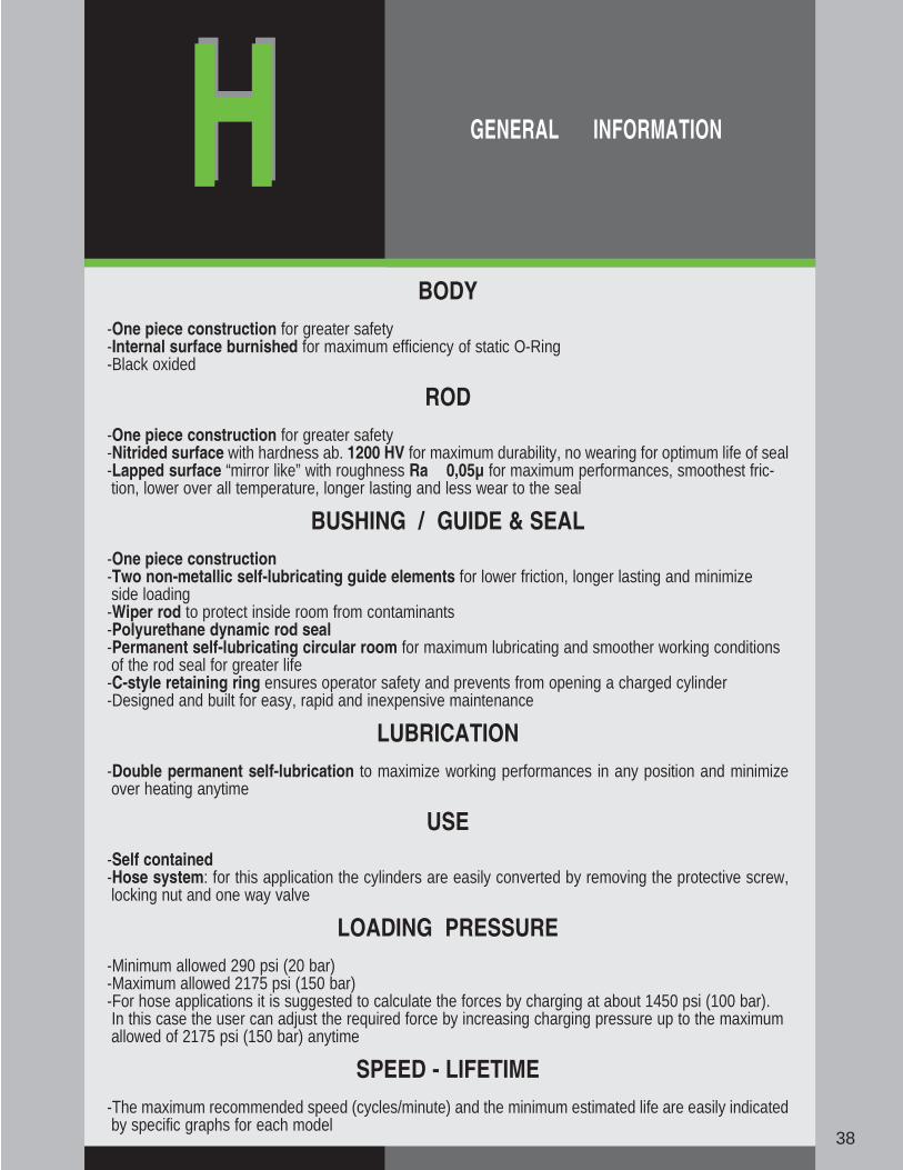
HH GENERAL INFORMATION
BODY-One piece construction for greater safety-Internal surface burnished for maximum efficiency of static O-Ring -Black oxided
ROD-One piece construction for greater safety-Nitrided surface with hardness ab. 1200 HV for maximum durability, no wearing for optimum life of seal-Lapped surface “mirror like” with roughness Ra � 0,05µ for maximum performances, smoothest fric-tion, lower over all temperature, longer lasting and less wear to the seal
BUSHING / GUIDE & SEAL-One piece construction-Two non-metallic self-lubricating guide elements for lower friction, longer lasting and minimize side loading
-Wiper rod to protect inside room from contaminants-Polyurethane dynamic rod seal-Permanent self-lubricating circular room for maximum lubricating and smoother working conditionsof the rod seal for greater life
-C-style retaining ring ensures operator safety and prevents from opening a charged cylinder-Designed and built for easy, rapid and inexpensive maintenance
LUBRICATION-Double permanent self-lubrication to maximize working performances in any position and minimizeover heating anytime
USE -Self contained-Hose system: for this application the cylinders are easily converted by removing the protective screw,locking nut and one way valve
LOADING PRESSURE-Minimum allowed 290 psi (20 bar) -Maximum allowed 2175 psi (150 bar) -For hose applications it is suggested to calculate the forces by charging at about 1450 psi (100 bar).In this case the user can adjust the required force by increasing charging pressure up to the maximumallowed of 2175 psi (150 bar) anytime
SPEED - LIFETIME-The maximum recommended speed (cycles/minute) and the minimum estimated life are easily indicatedby specific graphs for each model
38

one piece rod
self-lubricatingguide elements
bushing one piece body
O-Ring seal
permanent self-lubrication chamber
one way valvecharging hole plug
rod wiper
rod seal
ØD
inch mm
Series
H 300 H 500 H 700
H 1000 H 2400 H 4200 H 6600
H 18500
1.26
1.50
1.77
1.97
2.95
3.74
4.72
7.68
32
38
45
50
75
95
120
195
Cu
0.39 - 4.92
0.39 - 4.92
0.51 - 6.30
0.51 - 11.81
0.98 - 11.81
0.98 - 11.81
0.98 - 11.81
0.98 - 11.81
10 - 125
10 - 125
13 - 160
13 - 300
25 - 300
25 - 300
25 - 300
25 - 300
inch mm
L
inch mm
2.76 - 11.81
2.76 - 11.81
4.35 - 15.94
4.74 - 27.36
6.30 - 27.95
6.69 - 28.35
7.48 - 29.13
8.27 - 29.92
70 - 300
70 - 300
110,4 - 405
120,4 - 695
160 - 710
170 - 720
190 - 740
210 - 760
F0
675
1057
1530
2385
5372
9550
14920
41440
300
470
680
1060
2385
4240
6630
18400
lb. daN
40
42
44
46
48
50
52
54
Page
retaining ring
39
nut
HHF

H 300
��������
�������� ����
��
��
��
��������
±0,2
5
�������� Ø 16
±0,3Ø 32�����������
������
4
������
3,5
������
10,5
�������� Ø 30
�������� Ø 27
������
2�������
1
O r d e r i n g e x a m p l e :
(10) H 300 - 50
CodeCu L Lmin S F0 F1
0.39
0.51
0.63
0.98
1.50
1.97
2.48
3.15
3.94
4.92
10
13
16
25
38
50
63
80
100
125
2.76
2.97
3.23
3.94
4.96
5.91
6.97
8.27
9.84
11.81
70
75,4
82
100
126
150
177
210
250
300
0.31 2,01 2175 150 675 300 1215 540
inch mm inch mm inch mm in.2 cm2 psi bar lb. daN lb. daN
P Weight
~ lb. ~ Kg
2.36
2.47
2.60
2.95
3.46
3.94
4.47
5.12
5.91
6.89
60
62,7
66
75
88
100
113,5
130
150
175
0.64
0.66
0.68
0.75
0.84
0.95
1.06
1.19
1.35
1.52
0,29
0,30
0,31
0,34
0,38
0,43
0,48
0,54
0,61
0,69
H 300 - 010H 300 - 013H 300 - 016H 300 - 025H 300 - 038H 300 - 050H 300 - 063H 300 - 080H 300 - 100H 300 - 125
------------------------------
�
���
�
���
�
���
�
���
�
�
��
��
��
��
���
���
���
���
� ���������������������������
���
300
350
400
450
500
550
600
675
788
900
1013
1125
1238
1350
.39 .63 .98 1.5 1.97 2.48 3.15 3.94 4.92.51
Cu (inch)
Cyc
les
/min
.
Cyc
les
(inm
illio
ns)
Force (lbs. daN) / stroke (inch) diagram
For
ce(lb
s.da
N)
Cu (inch)
Minimum estimated life (cycles x millions) Maximum recommended speed (cycles / min.)
“All dimensions are nominal unless tolerance is stated”40
(±5%)

Fixing
�������� Ø 6,6 (4x)
�����
5�
������
50�
�����
35�
������ 50�
����� 35�
������ 7�
������Ø
32,
5
��������
Ø 2
8,5�
������ 4
��
��
����FS
232
������ 35�����
��������Ø
32,
5��
�������� Ø 2�
��������
Ø 6
,6 (
4x)
�
��������
Ø 6
0�
= =
������ 9�
��������Ø
34
�
�
��������
35�����
FC32
A
S = rod section areaP = nominal charging pressureF0 = nominal initial forceF1 = average final force
ISO11901- 2
41
HHF

H 500
��������������
�� �����
��������
1
�������� Ø 33
�������� Ø 36
������
3,5
������
4
Ø 38 �0,3����� �����
�������� Ø 20
��������
0,25
��
����
��� ��
2
������
10,5
O r d e r i n g e x a m p l e :
(10) H 500 - 50
CodeCu L Lmin S F0 F1
0.39
0.51
0.63
0.98
1.50
1.97
2.48
3.15
3.94
4.92
10
13
16
25
38
50
63
80
100
125
2.76
2.97
3.23
3.94
4.96
5.9
6.97
8.27
9.84
11.81
70
75,4
82
100
126
150
177
210
250
300
0.49 3,14 2175 150 1057 470 2320 1 030
inch mm inch mm inch mm in.2 cm2 psi bar lb. daN lb. daN
P Weight
~ lb. ~ Kg
2.36
2.47
2.60
2.95
3.46
3.94
4.47
5.12
5.91
6.89
60
62,7
66
75
88
100
113,5
130
150
175
0.93
0.95
0.99
1.10
1.24
1.39
1.55
1.74
1.96
2.40
0,42
0,43
0,45
0,50
0,56
0,63
0,70
0,79
0,89
1,08
H 500 - 010H 500 - 013H 500 - 016H 500 - 025H 500 - 038H 500 - 050H 500 - 063H 500 - 080H 500 - 100H 500 - 125
------------------------------
�
���
�
���
�
���
�
���
�
�
��
��
��
��
���
���
���
���
� ���������������������������
���
470
570
670
770
870
970
1070
1170
����
����
����
����
����
����
���
���
�����������������������������������������������������������������������������
��
Cu (inch)
Cyc
les
/min
.
Cyc
les
(inm
illio
ns)
Force (lbs. daN) / stroke (inch) diagram
For
ce(lb
s.da
N)
Cu (inch)
Minimum estimated life (cycles x millions) Maximum recommended speed (cycles / min.)
“All dimensions are nominal unless tolerance is stated”42
(±5%)

�����
56
������ 12
�������
������
50,3�������
�������
Ø 7
5
A
A
��������
��������������
A - A
������ ���� �50
������ ���� �29
�� ���
Ø 9�����
� ��� � 12��
� �� � 8��
������� ��� ���
�����������
� ����Ø
14����
�����������
�������� Ø 20
������
2,8
������
8
������
2,8
������ 4,1
����
5
�����
2��
��
��
���������
����������� ����
������� Ø35,7
���������
0,25
Fixing
�������� Ø 6,6 (4x)�
�����
5��������
55��
������
40�
������ 55�
������ 40�
������ 7�
�������Ø
38,
5
������Ø
34,
5�
������ 4
�
�
��FS
238
������ 40�����
��������Ø
38,
5��
�������� Ø 2�
�������
Ø 6
,6 (
4x)
�
������
Ø 6
8�
= =
������� 9�
��������Ø
40
��
��
����������
40�����
FC38
A
= =
A A
A
A
¯1.
57Ø
40¯
0.26
Ø6,
6(4
x) ¯1.
52Ø
38,5
0.35 9
2.05
52
1.57
40
2.05 52
1.57 40
FCQ
38A
HF 500
cod. GM 38
cod. FCA 38
ISO11901- 2
Threaded body cylinders
The HF are threaded body 500 springs with the same length and force as the H 500
Ordering example: (10) HF 500 - 5043
HHF

in.3 cm3
CodeCu L Lmin S V0F0 F1
0.51
0.98
1.50
1.97
2.48
3.15
3.94
4.92
6.30
13
25
38
50
63
80
100
125
160
4.35
5.31
6.34
7.28
8.35
9.65
11.22
13.19
15.94
110,4
135
161
185
212
245
285
335
405
0.70 4,52 2175 150 1530 680 2480 1 100
inch mm inch mm inch mm in.2 cm2 psi bar lb. daN lb. daN
H 700 - 013H 700 - 025H 700 - 038H 700 - 050H 700 - 063H 700 - 080H 700 - 100H 700 - 125H 700 - 160
P
3.85
4.33
4.84
5.31
5.85
6.50
7.28
8.27
9.65
97,7
110
123
135
148,5
165
185
210
245
2.16
2.36
2.56
2.76
2.98
3.25
3.8
3.97
4.52
0,98
1,07
1,16
1,25
1,35
1,47
1,72
1,80
2,05
Weight
~ lb. ~ Kg
1.92
2.86
3.85
4.72
5.78
7.02
8.51
10.37
13.04
31
46
62
76
93
113
137
167
210
H 700
��������
1
���������� ������
�������������
������
2
������
14,5
�������4
������
3,5
����������� Ø 45 ±0,3
�������� Ø 40
�������� Ø 43
������
10,5
���
� �!
���������
±0,2
5
��
�������� Ø 24
�������� Ø 20
O r d e r i n g e x a m p l e :
(10) H 700 - 50
�
���
���
���
���
���
���
���
���
�
��
��
���
���
���
���
���
���
��������������������������
680
780
880
980
1080
1180
1280
1380
����
����
����
����
����
���
����
����
���������������������������������������������������������������������������
Cu (inch)
Cyc
les
/min
.
Cyc
les
(inm
illio
ns)
Force (lbs. daN) / stroke (inch) diagram
For
ce(lb
s.da
N)
Cu (inch)
Minimum estimated life (cycles x millions) Maximum recommended speed (cycles / min.)
“All dimensions are nominal unless tolerance is stated”44
(±5%)

�����
62
������ 12,3
�������
������������
60�������
�������Ø
90
A
A
��������
��������������
A - A
��� � 34�������
���� � 60�������
�������
Ø 9����
����� � 16��
���� � 8��
������� ��� ���
= �����������
�������
Ø 1
4����
�������� Ø 24
������
2,8
������
8
������
2,8
������ 4,1
����
5
�����
2��
��
��
����������� ������
������
10,5
����������
������ Ø 42,7
���������
0,25
HF 700
cod. GM 45
FCA 45
Fixing
�������� Ø 9 (4x)�
������
20�
�����
70�
�������
50�
����� 70�
������ 50
������ 7�
����Ø
41,
5�
�� 4
��
��
����
������Ø
45,
5
FS2
45
����� � Ø 20�
����� � 70�
����� � 50
������7
0�
������5
0
�������Ø
15�����
�������Ø
18����
����� � ��
������� �20
����� � 14
A
A
A - A
����� �Ø
11�����
���� ��Ø
9����
FBA
45
�������� Ø 9 (2x)�
�������� Ø 9�
������ 70�
����� 50�
������
50�
�������
70��
��������Ø 20�������Ø
15
(2x)�
������ 12�
�������� 20
������ 14
��
��
����
������Ø
15
(4x)�
�������� Ø 11�
FB45
�����
25�
�����
70���
�����
57�
�� � 40�
��� � 27
���� � 7�
������
Ø 4
5,5�
������
Ø 4
1,5�
��� � 4
A
A
A - A
����� � Ø 9 ��� ��� �
FS2A
45������ 50��
�������Ø
45,
5��
�������� Ø 2�
��������
Ø 9
(4x
)��
��������
Ø 8
6�
= =
������ 13
�������Ø
47
�
�
��
������
50�����
FC45
A = =
A A
A
A
¯1.
85Ø
47¯
0.35
Ø9
(4x) ¯
1.79
Ø45
,5
0.51 13
2.52
64
1.97
50
2.52 64
1.97 50
FCQ
45A
ISO11901- 2
Threaded body cylinders
The HF are threaded body 700 springs with the same length and force as the H 700
Ordering example: (10) HF 700 - 5045
HHF

in.3 cm3
CodeCu L Lmin S V0F0 F1
0.51
0.98
1.50
1.97
2.48
3.15
3.94
4.92
6.30
7.87
9.84
11.81
13
25
38
50
63
80
100
125
160
200
250
300
4.74
5.71
6.73
7.68
8.74
10.04
11.61
13.58
16.34
19.49
23.43
27.36
120,4
145
171
195
222
255
295
345
415
495
595
695
1.09 7,07 2175 150 2385 1 060 3895 1 730
inch mm inch mm inch mm in.2 cm2 psi bar lb. daN lb. daN
H 1000 - 013H 1000 - 025H 1000 - 038H 1000 - 050H 1000 - 063H 1000 - 080H 1000 - 100H 1000 - 125H 1000 - 160H 1000 - 200H 1000 - 250H 1000 - 300
P
4.24
4.72
5.24
5.71
6.24
6.89
7.68
8.66
10.04
11.61
13.58
15.55
107,7
120
133
145
158,5
175
195
220
255
295
345
395
2.98
3.18
3.51
3.71
4.04
4.39
4.83
5.36
6.11
6.98
8.04
9.12
1,35
1,44
1,59
1,68
1,83
1,99
2,19
2,43
2,77
3,16
3,64
4,13
Weight
~ lb. ~ Kg
3.23
4.47
5.78
7.02
8.35
10.06
12.11
14.66
18.20
22.30
27.33
32.42
52
72
93
113
135
162
195
236
293
359
440
522
H 1000
���
���
��2
���������� ������
�������������
���
���
3
���
���
14,5
���
���
8
���
��5�
������ ����� Ø 50 �0,3
�������� Ø 43
�������� Ø 46
���
��
10,5
���
!�
"
��
�������� Ø 30
�������� Ø 20
��
��
���
���
0,25
O r d e r i n g e x a m p l e :
(10) H 1000 - 50
�
���
�
���
�
�
���
�
��
��
���
���
���
���
����������������������������������������
1060
1260
1460
1660
1860
2060
2260
2385
2835
3285
3735
4185
4635
5085
.51 1.50 2.48 3.94 4.92 6.3 7.87 9.84 11.81.98 1.97 3.15
Cu (inch)
Cyc
les
/min
.
Cyc
les
(inm
illio
ns)
Force (lbs. daN) / stroke (inch) diagram
For
ce(lb
s.da
N)
Cu (inch)
Minimum estimated life (cycles x millions) Maximum recommended speed (cycles / min.)
“All dimensions are nominal unless tolerance is stated”46
(±5%)

�������� Ø 30
������
2,8
������
8
������
2,8
������ 4,1
�����
5
������
2
���
�
������������������
������
10
����������
������� Ø 47,7
����������
0,25
FixingISO11901- 2
47
�����
66�������
�������
Ø 1
00
�
�
�������
������ ���������
���
������� ��� � 38�������
���� � 66�������
�������
Ø 9�����
���� � 16
��� � 8��
������� �� ���
�������Ø
14������
� �
��������
68
������ 12,9
�������
HF 1000
cod. GM 50
cod. FCA 50
������ �Ø 20�
����� � 75�
����� � 56,5
������7
5�
� �����5
6,5
�������Ø
15�����
�������Ø
18�����
����� � ��
������� �20
������ 14
A
A
A - A
����� �Ø
11�����
���� ��Ø
9����
FBA
50
�������� Ø 9 (2x)�
�������� 75��
��������� 56,5�
���������
56,5�
��������
75�
���������Ø 20��������
Ø 1
5��������
Ø 1
5�
������ 12
���� 20
������� 14
�
�
��
�������� Ø 9�
������� Ø 11�
FB50
������ � Ø 9 ������ �
����
25�
����
75���
�����
62�
��� � 45�
��� � 32
���� � 12�
�� ��
Ø 5
0,5�
�� ����
Ø 4
4,5�
��� � 8
A
A
A - A
FS2A
50
�������� Ø 9 (4x)�
������
24�
������
75�
������
56,5��
������ 75
������ 56,5
����� 12�
������Ø
50,
5
�����Ø
44,
5
��� 8
��
��
����
FS2
50
= =
A A
A
A
¯2.
13Ø
54¯
0.35
Ø9
(4x) ¯
1.99
Ø50
,5
0.51 13
2.75
70
2.22
56,5
2.75 70
2.22 56,5
FCQ
50A
������ 56,5����
��������Ø
50,
5�
�������� Ø 4�
�������
Ø 9
(4x
)�
�������
Ø 9
5�
= =
������ 13
��������Ø
54�
�
�
� �
������
56,5�����
FC50
A
���
������
110� ������
50�
������ 30
�����
130�
������
60�
������ 80�
��
����� 20
�� ����
Ø 9
(2x
)�
�����
90�
������
40�
��������Ø
50
�������
37,5�
FSA
50
Threaded body cylinders
The SCF are threaded body 750 springs with the same length and force as the SC 750
Ordering example: (10) SCF 750 - 50
HHF

in.3 cm3
CodeCu L Lmin S V0F0 F1
0.98
1.50
1.97
2.48
3.15
3.94
4.92
6.30
7.87
9.84
11.81
25
38
50
63
80
100
125
160
200
250
300
6.30
7.32
8.27
9.33
10.63
12.20
14.17
16.93
20.08
24.02
27.95
160
186
210
237
270
310
360
430
510
610
710
2.47 15,90 2175 150 5372 2 385 9540 4 240
inch mm inch mm inch mm in.2 cm2 psi bar lb. daN lb. daN
H 2400 - 025H 2400 - 038H 2400 - 050H 2400 - 063H 2400 - 080H 2400 - 100H 2400 - 125H 2400 - 160H 2400 - 200H 2400 - 250H 2400 - 300
P
5.31
5.83
6.30
6.83
7.48
8.27
9.25
10.63
12.20
14.17
16.14
135
148
160
173,5
190
210
235
270
310
360
410
8.17
8.74
9.29
9.93
10.62
11.55
12.52
14.30
16.53
20.66
24.79
3,70
3,96
4,21
4,50
4,81
5,23
5,67
6,48
7,49
9,36
11,23
Weight
~ lb. ~ Kg
10.81
13.80
16.52
19.63
23.42
28.00
33.73
41.74
50.87
62.30
73.73
174
222
266
316
377
451
543
672
819
1003
1187
H 2400
������2
,5
�����������
� ������� ��������
�������� Ø 40
�������� Ø 45
�
�����1
0.5
���
����
������
18
�����
8
�����
5
Ø 75 0,3����!� ����
�� ������
0,25
����"��� Ø 67
�������"�� Ø 70
������
3
O r d e r i n g e x a m p l e :
(10) H 2400 - 50
�
���
�
���
�
�
��
��
��
��
���
���
����������������������������������������������������������������������������������������������
2385
2875
3375
3875
4375
4875
5375
����
����
����
����
���
����
��������������������������������������
�����
Cu (inch)
Cyc
les
/min
.
Cyc
les
(inm
illio
ns)
Force (lbs. daN) / stroke (inch) diagram
For
ce(lb
s.da
N)
Cu (inch)
Minimum estimated life (cycles x millions) Maximum recommended speed (cycles / min.)
“All dimensions are nominal unless tolerance is stated”48
(±5%)
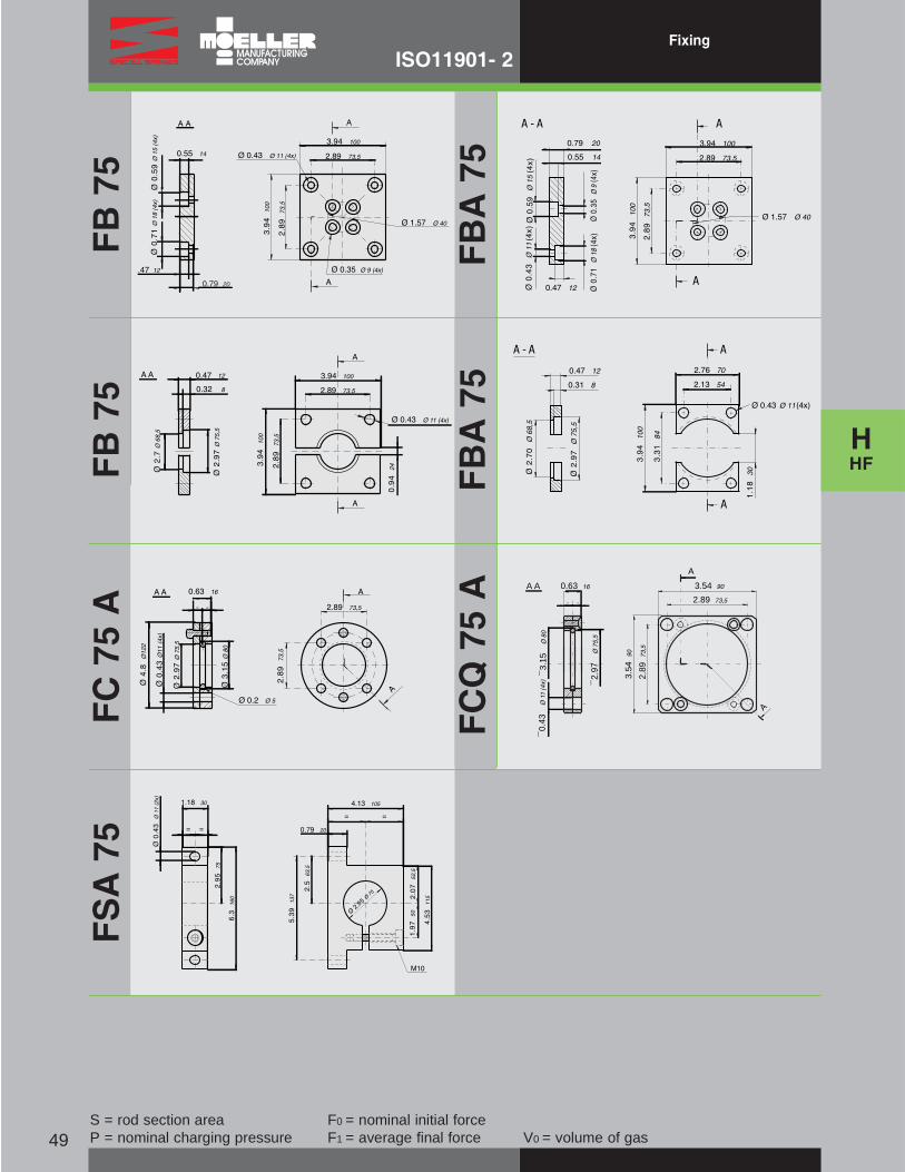
FixingISO11901- 2
S = rod section areaP = nominal charging pressure
F0 = nominal initial forceF1 = average final force V0 = volume of gas49
������ Ø 40�
����� 100�
��� 73,5
���
73,5
������
100�
�������
Ø 1
8���� ��
����� 12
�������� 20
A
A
A - A
�������
Ø 1
1���� ���������
Ø 1
5���� ��
�������
Ø 9
���� ��
�������� 14
FBA
75
���� 20
�������� Ø 11 (4x)�
������� Ø 9 (4x)
��������� 100�
������� 73,5���
��������
73,5����
��������
100�
�������Ø
15
(4x)�
�������Ø
18
(4x)��
����� 12�
������� 14�
��
��
����
� ������ Ø 40�
������� � Ø 11 ���� ���� �
��
30�
�����
100���
����
84�
�� � � 70�
��� � 54
��� � 12�
����� �
Ø 7
5,5�
���� ��
Ø 6
8,5�
��� � 8
A
A
A - A
�������� Ø 11 (4x)�
������
24�������
100��
�������
73,5�
������ 100�
������� 73,5
����� 12�
������Ø
75,
5�
�����Ø
68,
5
���� 8
�
�
��
= =
A A
A
A
¯3.
15Ø
80¯
0.43
Ø11
(4x) ¯
2.97
Ø75
,5 0.63 16
3.54
90
2.89
73,5
3.54 90
2.89 73,5������� 73,5����
��������Ø
75,
5�
������� Ø 5�
�������Ø
11 (
4x)
�
������
Ø12
2�
= =
������ 16
����� �Ø
80
��
��
����
�������
73,5�����
����
������
137�
�����
63,5�
����� 30
�����
160�
������
75�
������ 105�
��
�� ��� 20
��������
Ø 1
1 (2
x)�
������
115���� ��
52,5�
��������Ø
75
��� ��
50�
FB75
FBA
75
FB75
FCQ
75A
FC75
AFS
A75
HHF

in.3 cm3
CodeCu L Lmin S V0F0 F1
0.98
1.50
1.97
2.48
3.15
3.94
4.92
6.30
7.87
9.84
11.81
25
38
50
63
80
100
125
160
200
250
300
6.69
7.72
8.66
9.72
11.02
12.60
14.57
17.32
20.47
24.41
28.35
170
196
220
247
280
320
370
440
520
620
720
4.38 28,27 2175 150 9550 4 240 17330 7700
inch mm inch mm inch mm in.2 cm2 psi bar lb. daN lb. daN
H 4200 - 025H 4200 - 038H 4200 - 050H 4200 - 063H 4200 - 080H 4200 - 100H 4200 - 125H 4200 - 160H 4200 - 200H 4200 - 250H 4200 - 300
P
5.71
6.22
6.69
7.22
7.87
8.66
9.65
11.02
12.60
14.57
16.54
145
158
170
183,5
200
220
245
280
320
370
420
14.44
15.45
16.27
17.31
18.43
20.53
21.63
23.18
24.94
27.15
29.36
6,54
7,00
7,37
7,84
8,35
9,30
9,80
10,5
11,3
12,3
13,3
Weight
~ lb. ~ Kg
19.25
24.16
28.70
33.80
40.00
47.51
56.89
70.00
85.15
104.0
122.6
310
389
462
544
644
765
916
1128
1371
1674
1974
H 4200
�������
2,5
�����������
� ������� ��������
������� Ø 60
������� Ø 60
�
������
10.5
���
����
����
21
�����
8
�����
5
����� ���� Ø 95 0,3
�� ������
0,25
������ Ø 87
���!��� Ø 90
������
3
O r d e r i n g e x a m p l e :
(10) H 4200 - 50
�
���
�
���
�
�
��
��
��
��
��
��
��
�
�
��������������������������������������������������������������������������������������������
4240
5240
6240
7240
8240
9240
10240
����
�����
�����
�����
�����
�����
�����
��������������������������������
Cu (inch)
Cyc
les
/min
.
Cyc
les
(inm
illio
ns)
Force (lbs. daN) / stroke (inch) diagram
For
ce(lb
s.da
N)
Cu (inch)
Minimum estimated life (cycles x millions) Maximum recommended speed (cycles / min.)
50“All dimensions are nominal unless tolerance is stated”
(±5%)

Fixing
�������� Ø 13,5 (4x)
�������� Ø 9 (4x)
������ 120�
����� 92
�������
92��
�������
120��
�������
Ø 1
5 (4
x)��
������� 14
��
��
����
������� Ø 60
��� 20
�������
Ø 2
0 (4
x)�
������� 13
���� 8
�������� Ø 13,5 (4x)
�����
24�
�����
120�
��������
92,0
���� 120�
������� 92,0�
���� 12�
������Ø
95,
5�
���� �Ø
88,
5
��
��
����
������ 92��
��������Ø
95,
5��
������� Ø 5�
������
Ø 1
3 (4
x)�
������
Ø15
0�
= =
������ 18�
��������Ø
100�
�
�
� �
�������
92�����
����
������
170� ������
80�
����� 30
�����
195�
������
92,5�
������ 125�
��
����� 20
�� �����
Ø 1
3,5
(2x)�
������
145�
�������
67,5�
��������Ø
95
�������
62,5�
FB95
������ Ø 60�
����� 120�
����� 92
�����
92
������
120�
������
Ø 2
0������
�� �� 13
������� 20
A
A
A - A
���� ��
Ø 1
3,5
���������
���� �
Ø 1
5������
����� �
Ø 9
������
����� � 14
������� � Ø 13,5 ��� �
����
40�
�����
120���
�� ��
100�
���� � 90�
���� � 70
���� � 12�
�������
Ø 9
5,5�
�������
Ø 8
8,5�
��� � 8
A
A
A - A
= =
A A
A
A
¯3.
94Ø
100
¯0.
51Ø
13(4
x) ¯3.
76Ø
95,5
0.71 18
4.33
110
3.62
924.33 110
3.62 92
FBA
95
FS2
95
FS2A
95
FC95
A
FCQ
95A
FSA
95
51
ISO11901- 2
S = rod section areaP = nominal charging pressure
F0 = nominal initial forceF1 = average final force V0 = volume of gas
HHF

in.3 cm3
CodeCu L Lmin S V0F0 F1
0.98
1.50
1.97
2.48
3.15
3.94
4.92
6.30
7.87
9.84
11.81
25
38
50
63
80
100
125
160
200
250
300
7.48
8.50
9.45
10.51
11.81
13.39
15.35
18.11
21.26
25.20
29.13
190
216
240
267
300
340
390
460
540
640
740
6.85 44,18 2175 150 14920 6 630 28150 12510
inch mm inch mm inch mm in.2 cm2 psi bar lb. daN lb. daN
H 6600 - 025H 6600 - 038H 6600 - 050H 6600 - 063H 6600 - 080H 6600 - 100H 6600 - 125H 6600 - 160H 6600 - 200H 6600 - 250H 6600 - 300
P
6.50
7.01
7.48
8.01
8.66
9.45
10.43
11.81
13.39
15.35
17.32
165
178
190
203,5
220
240
265
300
340
390
440
26.71
30.24
33.33
34.22
35.54
38.63
42.60
48.12
54.53
62.47
70.42
12,1
13,7
15,1
15,5
16,1
17,5
19,3
21,8
24,7
28,3
31,9
Weight
~ lb. ~ Kg
29.56
36.83
43.60
51.18
60.50
71.74
85.78
105.5
127.9
156.0
184.4
476
593
702
824
974
1155
1381
1698
2060
2512
2969
H 6600
������2
,5
������������
�� ����������������
�������� ��80
�������� Ø 75
��
������
10.5
���
���
������
22,5
�����8
�����
5
����!� "���� Ø 120 "0.3
��"������"
0,25
���������� Ø 112
�������� Ø 115
������
3
O r d e r i n g e x a m p l e :
(10) H 6600 - 50
�
�
�
�
��
��
��
��
��
��
��
��
�
��
��
��������������������������������������������������������������������������������������
6630
7630
8690
9630
10630
11630
12630
13630
14630
15630
16630
14920
17170
19420
21670
23920
26170
28420
30670
32920
35170
37420
.98 1.97 3.15 3.94 4.92 6.3 7.87 9.84 11.811.50 2.48
Cu (inch)
Cyc
les
/min
.
Cyc
les
(inm
illio
ns)
Force (lbs. daN) / stroke (inch) diagram
For
ce(lb
s.da
N)
Cu (inch)
Minimum estimated life (cycles x millions) Maximum recommended speed (cycles / min.)
52“All dimensions are nominal unless tolerance is stated”
(±5%)

Fixing
53
ISO11901- 2
S = rod section areaP = nominal charging pressure
F0 = nominal initial forceF1 = average final force V0 = volume of gas
����
�������� Ø 13,5 (4x)�
�������� Ø 11 (4x)�
������� 140�
�������� 109,5�
�������
109,
5��
������
140��
�������
Ø 1
8 (4
x)������� 15�
�
�
��
������� Ø 80�
20
��������
Ø 2
0 (4
x)
������ 13�
���� 8
�������� Ø 13 (4x)�
�����
24�
������
140�
�����
109,
5��
������ 140�
����� 109,5�
���� 12�
����Ø
120
,5
����Ø
113
,5
��
��
����
������ 109,5�����
��������Ø
120
,5���
������� Ø 5
��������
Ø 1
3,5
(4x)
�
���� ��
Ø 1
75�
= =
������� 21
����� ��Ø
125�
��
��
����
�������
109,
5�����
����
������
195�
�����
92,5�
������ 30
������
220�
�����
105�
������ 148�
��
��� �� 20
��������
Ø 1
3,5
(2x)
�
�� ��
165�������
77,5�
�������Ø
120
�� ���
74�
FB12
0
������ Ø 80�
����� 140�
����� 109,5
�����
109,
5
������
140�
������
Ø 2
0������
����� ��
������� 20
A
A
A - A
�������
Ø 1
3,5
����������������
Ø 1
8
������
�������
Ø
�������
������� 15
������� � Ø 13,5 ��� �
����
50�
����
140���
��� �
120�
���� � 115�
��� � 95
���� � 12�
�������
Ø 1
20,5�
�������
Ø 1
13,5�
��� � 8
A
A
A - A
= =
A A
A
A
¯4.
92Ø
125
¯0.
53Ø
13,5
(4x) ¯
4.74
Ø12
0,5
0.83 21
5.12
130
4.31
109.
55.12 130
4.31 109.5
FBA
120
FS2
120
FS2A
120
FC12
0A
FCQ
120
A
FSA
120
HHF

H 18500
��������������
�����
2,5
� ������ ���������
�������� Ø 120
�����
30,5
�����
10.5
���
��
��������
0,25
�����
3�����
8
�����
8
������� Ø 190
�������� Ø 187
������ ��� Ø 195 �0.3
��
���
���� ��� Ø 125
O r d e r i n g e x a m p l e :
(10) H 18500 - 100
in.3 cm3
CodeCu L Lmin S V0F0 F1
0.98
1.50
1.97
2.48
3.15
3.94
4.92
6.30
7.87
9.84
11.81
25
38
50
63
80
100
125
160
200
250
300
8.27
9.29
10.23
11.30
12.60
14.17
16.14
18.90
22.05
25.98
29.92
210
236
260
287
320
360
410
480
560
660
760
19.0 122,7 2175 150 41440 18400 77770 34530
inch mm inch mm inch mm in.2 cm2 psi bar lb. daN lb. daN
H 18500 - 025H 18500 - 038H 18500 - 050H 18500 - 063H 18500 - 080H 18500 - 100H 18500 - 125H 18500 - 160H 18500 - 200H 18500 - 250H 18500 - 300
P
7.28
7.79
8.27
8.80
9.45
10.24
11.22
12.60
14.17
16.14
18.11
185
198
210
223,5
240
260
285
320
360
410
460
72.6
75.9
79.0
82.3
85.6
91.6
99.6
106.6
116.8
127.4
140.8
32,9
34,4
35,8
37,3
38,8
41,5
45,1
48,3
52,9
57,7
63,8
Weight
~ lb. ~ Kg
103.0
125.3
146.0
169.2
197.6
232.0
275.1
335.3
404.2
490.2
576.3
1658
2018
2351
2725
3182
3736
4429
5399
6507
7893
9278
�
���
�
���
�
���
�
��
��
��
��
��
��
��
�
�
��������������������������������������������������������������������������������������������
18400
23400
28400
33400
43400
48400
�����
�����
�����
�����
�����
������
��������������������������������
38400�����
Cu (inch)
Cyc
les
/min
.
Cyc
les
(inm
illio
ns)
Force (lbs. daN) / stroke (inch) diagram
For
ce(lb
s.da
N)
Cu (inch)
Minimum estimated life (cycles x millions) Maximum recommended speed (cycles / min.)
“All dimensions are nominal unless tolerance is stated”54
(±5%)

FixingISO11901- 2
���� 25
�������� Ø 17,5 (4x)
�������� Ø 13,5 (4x)�
������ 210
��������� 170
�������
170�
�����
210�
�������
Ø 2
0�
������� 13
��
��
����
�� ��� Ø 120
�������
Ø 2
6�
����� 17FB19
5
������ Ø 120�
����� 210�
����� 170
�����
170
������
210
�
������
Ø 2
6������
����� �
����� �� 25
A
A
A - A
����� �
Ø 1
7,5
�������������� �
Ø 2
0
������
�������
Ø
��������
������ � 15
FBA
195
�������� Ø 17,5 (4x)�
������
24�
�����
210��
������
170��
����� 210�
������� 170
������ 13�
�����Ø
195
,5
������Ø
188
�
�
� �
���� 8
FS2
195
������� � Ø 17,5 ��� �
����
80� ����
210���
��� �
185
��� � 190�
���� � 165
���� � 13
�������
Ø 1
95,5�
�������
Ø 1
88�
��� � 8
A
A
A - A
FS2A
195
������ 170����
��������Ø
195
,5��
������� Ø 5
���������
Ø 1
7,5
(4x)
�
������
Ø 2
90�
= =
������ 27
��������Ø
200
��
��
����
������
170�����
FC19
5A
= =
A A
A
A
¯7.
87Ø
200
¯0.
69Ø
17,5
(4x) ¯
7.70
Ø19
5,5
1.06 27
8.27
210
6.70
170
8.27 210
6.70 170
FCQ
195
A
S = rod section area P = nominal charging pressure F0 = nominal initial force F1 = average final force V0 = volume of gas
55
HHF

HRHR GENERAL INFORMATION
BODY-One piece construction for greater safety-Black oxided
ROD-One piece construction for greater safety-Nitrided surface with hardness ab. 1200 HV for maximum durability, no wearing for optimum life of seal-Lapped surface “mirror like” with roughness Ra � 0,05µ for maximum performances, smoothest fric-tion, lower over temperature, longer lasting and less wear to the seal
BUSHING / GUIDE & SEAL-One piece construction-Two non-metallic self-lubricating guide elements for lower friction, longer lasting and minimize side loading
-Wiper rod to protect inside room from contaminants-Polyurethane dynamic rod seal-C-style retaining ring ensures operator safety and prevents from opening a charged cylinder-Designed and built for easy, rapid and inexpensive maintenance
USE -Self contained-Hose system: for this application the cylinders are easily converted by removing the protective screw,locking nut and one way valve (except HR 700 subjected to supply a specific .39” higher body)
LOADING PRESSURE-Minimum allowed 290 psi (20 bar) -Maximum allowed 2175 psi (150 bar), except HR 200 charged at 2537.5 psi (175 bar) -For hose applications it is suggested to calculate the forces by charging at about 1450 psi (100 bar).In this case the user can adjust the required force by increasing charging pressure up to the maximumallowed of 2175 psi (150 bar) anytime
SPEED - LIFETIME-The maximum recommended speed (cycles/minute) and the minimum estimated life are easily indicatedby specific graphs for each model
56

one piece rod
self-lubricatingguide elements
bushing
retaining ring
one piece body
rod seal
O-Ring seal
one way valvecharging hole plug nut
rod wiper
57
ØD
inch mm
Series
HR 200HR 300 HR 500 HR 700
HR 1000 HR 1500 HR 2400 HR 4200 HR 6600
HR 11800
0.98
1.26
1.50
1.77
1.97
2.48
2.95
3.74
4.72
5.90
25
32
38
45
50
63
75
95
120
150
Cu
0.20 - 1.26
0.20 - 4.92
0.20 - 4.92
0.39 - 4.92
0.39 - 4.92
0.39 - 4.92
0.39 - 4.92
0.63 - 4.92
0.63 - 4.92
0.75 - 4.92
5 - 32
5 - 125
5 - 125
10 - 125
10 - 125
10 - 125
10 - 125
16 - 125
16 - 125
19 - 125
inch mm
L
inch mm
1.57 - 3.70
1.57 - 11.02
1.57 - 11.02
2.05 - 11.10
2.28 - 11.34
2.52 - 11.57
2.56 - 11.61
3.82 - 12.40
4.21 - 12.80
4.57 - 12.91
40 - 94
40 - 280
40 - 280
52 - 282
58 - 288
64 - 294
65 - 295
97 - 315
107 - 325
116 - 328
F0
450
675
1058
1530
2385
3442
5366
9540
14920
26510
200
300
470
680
1060
1530
2385
4240
6630
11780
lb. daN
58606264666870727476
Page
HRHRF

�������
1
�������� Ø 12
���
��
�� ���
8
������� ������� Ø 25 �0,3
����������
0,25
������
1
���������
����������������
������ Ø 23
HR 200
O r d e r i n g e x a m p l e :
(10) HR 200 - 25
CodeCu L Lmin SD E ØF F0 F1
0.20
0.39
0.51
0.63
0.75
0.98
1.26
5
10
13
16
19
25
32
1.57
1.97
2.20
2.44
2.68
3.15
3.70
40
50
56
62
68
80
94
0.18 1,13 2537 175 450 200 653 290
inch mm inch mm inch mm in.2 cm2 psi barinch mm inch mm inch mm lb. daN lb. daN
P Weight
~ lb. ~ Kg
1.38
1.57
1.69
1.81
1.93
2.17
2.44
35
40
43
46
49
55
62
HR 200 - 005HR 200 - 010HR 200 - 013HR 200 - 016HR 200 - 019HR 200 - 025HR 200 - 032
---------------
-
-
-
-
-
-
-
-
-
-
-
-
-
-
-
-
-
-
-
-
-
-
-
-
-
-
-
-
-
-
-
-
-
-
-
-
-
-
-
-
-
-
2
3
3.5
4
100
110
120
130
140
150
160
0 0.2 0.39 0.98 1.260.750.51 0.63
2.5
1.5
4.5
5 170
200
220
240
260
280
300
320
���
���
���
�����
�����
�����
����
����������������������������������������������������������������������������������������������������
Cu (inch)
Cyc
les
/min
.
Cyc
les
(inm
illio
ns)
Force (lbs. daN) / stroke (inch) diagram
For
ce(lb
s.da
N)
Cu (inch)
Minimum estimated life (cycles x millions) Maximum recommended speed (cycles / min.)
58“All dimensions are nominal unless tolerance is stated”
0.19
0.22
0.22
0.24
0.27
0.29
0.36
0,09
0,10
0,10
,0,11
0,12
0,13
0,16
(±5%)

Fixing
4 Ø 0.28 Ø 7
2 x M5
1.
34 3
4
0.71 18
1.18 30
Ø 1
.97
Ø 5
0
=
0.35 9
Ø 1
.06
Ø 2
7
=
A
A
A A
Ø 1
.00
Ø 2
5,5
FC25
A
59
S = rod section areaP = nominal charging pressureF0 = nominal initial forceF1 = average final force
ISO11901- 2
HRHRF

�������
1
�������� Ø 16
��
��
������
10.5
��
������� ������� Ø 32 �0,3
����������
0,25
������
1
���
��������
����������������
������ Ø 30
HR 300
O r d e r i n g e x a m p l e :
(10) HR 300 - 50
CodeCu L Lmin SD E ØF F0 F1
0.20
0.39
0.51
0.63
0.75
0.98
1.26
1.50
1.97
2.48
2.95
3.15
3.94
4.92
5
10
13
16
19
25
32
38
50
63
75
80
100
125
1.57
1.97
2.20
2.44
2.68
3.15
3.70
4.17
5.12
6.14
7.08
7.48
9.06
11.0
2
40
50
56
62
68
80
94
106
130
156
180
190
230
280
0.31 2,01 2175 150 675 300 1148 510
inch mm inch mm inch mm in.2 cm2 psi barinch mm inch mm inch mm lb. daN lb. daN
P Weight
~ lb. ~ Kg
1.38
1.57
1.69
1.81
1.93
2.17
2.44
2.68
3.15
3.66
4.13
4.33
5.12
6.10
35
40
43
46
49
55
62
68
80
93
105
110
130
155
HR 300 - 005HR 300 - 010HR 300 - 013HR 300 - 016HR 300 - 019HR 300 - 025HR 300 - 032HR 300 - 038HR 300 - 050HR 300 - 063HR 300 - 075HR 300 - 080HR 300 - 100HR 300 - 125
------------------------------------------
-
-
-
-
0.14
0.14
0.14
0.14
0.14
0.14
0.14
0.14
0.14
0.14
-
-
-
-
3,5
3,5
3,5
3,5
3,5
3,5
3,5
3,5
3,5
3,5
-
-
-
-
0.16
0.16
0.16
0.16
0.16
0.16
0.16
0.16
0.16
0.16
-
-
-
-
4
4
4
4
4
4
4
4
4
4
-
-
-
-
1.06
1.06
1.06
1.06
1.06
1.06
1.06
1.06
1.06
1.06
-
-
-
-
27
27
27
27
27
27
27
27
27
27
�
���
�
���
�
���
�
���
�
�
��
��
��
��
���
���
���
���
����������������������������� ��� ���� ���
���
300
350
400
450
500
550
600
���
���
���
����
����
����
����
����������������������������������
Cu (inch)
Cyc
les
/min
.
Cyc
les
(inm
illio
ns)
Force (lbs. daN) / stroke (inch) diagram
For
ce(lb
s.da
N)
Cu (inch)
Minimum estimated life (cycles x millions) Maximum recommended speed (cycles / min.)
60“All dimensions are nominal unless tolerance is stated”
0.38
0.40
0.42
0.44
0.49
0.55
0.60
0.64
0.75
0.86
0.94
0.99
1.17
1.52
0,17
0,18
0,19
0,20
0,22
0,25
0,27
0,29
0,34
0,39
0,42
0,45
0,53
0,68
(±5%)

Fixing
�������� Ø 6,6 (4x)
�����
5�
������
50�
�����
35�
������ 50�
����� 35�
������ 7�
������Ø
32,
5
��������
Ø 2
8,5�
������ 4
��
��
����FS
232
������ 35�����
��������Ø
32,
5��
�������� Ø 2�
��������
Ø 6
,6 (
4x)
�
��������
Ø 6
0�
= =
������ 9�
��������Ø
34
�
�
��������
35�����
FC32
A
61
S = rod section areaP = nominal charging pressureF0 = nominal initial forceF1 = average final force
ISO11901- 2
HRHRF

HR 500�������1
�������� Ø 20
�
�� �
�������
10.5
��
������� ������� Ø 38 �0,3
���������0,
25
������
1
���
��������������
�������
������ Ø 36
O r d e r i n g e x a m p l e :
(10) HR 500 - 50
CodeCu L Lmin SD E ØF F0 F1
0.20
0.39
0.51
0.63
0.75
0.98
1.26
1.50
1.97
2.48
2.95
3.15
3.94
4.92
5
10
13
16
19
25
32
38
50
63
75
80
100
125
1.57
1.97
2.20
2.44
2.68
3.15
3.70
4.17
5.12
6.14
7.08
7.48
9.06
11.02
40
50
56
62
68
80
94
106
130
156
180
190
230
280
0.49 3,14 2175 150 1058470 2115 940
inch mm inch mm inch mm in.2 cm2 pas barinch mm inch mm inch mm lb. daN lb. daN
P Weight
~ lb. ~ Kg
1.38
1.57
1.69
1.81
1.93
2.17
2.44
2.68
3.15
3.66
4.13
4.33
5.12
6.10
35
40
43
46
49
55
62
68
80
93
105
110
130
155
HR 500 - 005HR 500 - 010HR 500 - 013HR 500 - 016HR 500 - 019HR 500 - 025HR 500 - 032HR 500 - 038HR 500 - 050HR 500 - 063HR 500 - 075HR 500 - 080HR 500 - 100HR 500 - 125
------------------------------ --- ---------
-
-
-
-
0.14
0.14
0.14
0.14
0.14
0.14
0.14
0.14
0.14
0.14
-
-
-
-
3,5
3,5
3,5
3,5
3,5
3,5
3,5
3,5
3,5
3,5
-
-
-
-
0.16
0.16
0.16
0.16
0.16
0.16
0.16
0.16
0.16
0.16
-
-
-
-
4
4
4
4
4
4
4
4
4
4
-
-
-
-
1.30
1.30
1.30
1.30
1.30
1.30
1.30
1.30
1.30
1.30
-
-
-
-
33
33
33
33
33
33
33
33
33
33
�
���
�
���
�
���
�
���
�
�
��
��
��
��
���
���
���
���
����������������������������� ��� ���� ���
���
470
570
670
770
870
970
1070
����
����
����
����
����
����
����
����������������������������������
Cu (inch)
Cyc
les
/min
.
Cyc
les
(inm
illio
ns)
Force (lbs. daN) / stroke (inch) diagram
For
ce(lb
s.da
N)
Cu (inch)
Minimum estimated life (cycles x millions) Maximum recommended speed (cycles / min.) 62
“All dimensions are nominal unless tolerance is stated”
0.55
0.60
0.64
0.68
0.74
0.79
0,89
0.97
1.10
1.26
1.36
1.46
1.70
2.01
0,25
0,27
0,29
0,31
0,33
0,36
0,40
0,44
0,50
0,57
0,61
0,66
0,77
0,90
(±5%)

Ø 0.79 Ø 20
0.11
2,8
0.31
8
0.11
2,8
0.16 4,1
0.2
5
0.08
2
Cu
L m
in
L
0,
25
M 38 x 1,5
Ø 1.40 Ø 35,7
CHARGING HOLE M6
HRF 500
Fixing
�������� Ø 6,6 (4x)�
�����
5��������
55��
������
40�
������ 55�
������ 40�
������ 7�
�������Ø
38,
5
������Ø
34,
5�
������ 4
�
�
��FS
238
������ 40�����
��������Ø
38,
5��
�������� Ø 2�
�������
Ø 6
,6 (
4x)
�
������
Ø 6
8�
= =
������� 9�
��������Ø
40
��
��
����������
40�����
FC38
A
= =
A A
A
A
¯1.
57Ø
40¯
0.26
Ø6,
6(4
x) ¯1.
52Ø
38,5
0.35 9
2.05
52
1.57
40
2.05 52
1.57 40
FCQ
38A
63
ISO11901- 2
Threaded body cylinders
The HRF are threaded body 500 springs with the same length and force as the HR 500
Ordering example: (10) HRF 500 - 50
������
50,3�������
�������
Ø 7
5
A
A
��������
��������������
A - A
������ ���� �50
������ ���� �29
�� ���
Ø 9�����
� ��� � 12��
� �� � 8��
������� ��� ���
�����������
� ����Ø
14����
�����������
cod. GM 38
cod. FCA 38
HRHRF

HR 700�������1
�������� Ø 24
��
��
������
14.
5�����4
�����3
,5
����������0,
25
������
1
������� Ø 40
������������
�������� Ø 20
����������������
������ ����� Ø 45 �0,3
������ Ø 43
O r d e r i n g e x a m p l e :
(10) HR 700 - 50
in.3 cm3
CodeCu L Lmin S V0F0 F1
0.39
0.51
0.63
0.75
0.98
1.26
1.50
1.97
2.48
2.95
3.15
3.94
4.92
10
13
16
19
25
32
38
50
63
75
80
100
125
2.05
2.28
2.52
2.76
3.23
3.78
4.25
5.20
6.22
7.16
7.56
9.13
11.10
52
58
64
70
82
96
108
132
158
182
192
232
282
0.70 4,52 2175 150 1530 680 3060 1 360
inch mm inch mm inch mm in.2 cm2 psi bar lb. daN lb. daN
HR 700 - 010HR 700 - 013HR 700 - 016HR 700 - 019HR 700 - 025HR 700 - 032HR 700 - 038HR 700 - 050HR 700 - 063HR 700 - 075HR 700 - 080HR 700 - 100HR 700 - 125
P
1.65
1.77
1.89
2.01
2.24
2.52
2.76
3.23
3.74
4.21
4.41
5.20
6.18
42
45
48
51
57
64
70
82
95
107
112
132
157
Weight
~ lb. ~ Kg
0.8
1.06
1.24
1.30
1.74
2.24
2.73
3.60
4.53
5.34
5.78
7.21
9.01
13
17
20
21
28
36
44
58
73
86
93
116
145
�
���
���
���
���
���
���
���
���
�
��
��
���
���
���
���
���
��� �����
��� ��� ���� ����
���
����
���
����������
680
780
880
980
1080
1180
1280
1380
1480
����
����
����
����
����
���
����
����
����
����������������������������������������������������������������������������
������������������������������������������������
Cu (inch)
Cyc
les
/min
.
Cyc
les
(inm
illio
ns)
Force (lbs. daN) / stroke (inch) diagram
For
ce(lb
s.da
N)
Cu (inch)
Minimum estimated life (cycles x millions) Maximum recommended speed (cycles / min.)
64“All dimensions are nominal unless tolerance is stated”
0.87
0.93
1.00
1.06
1.17
1.29
1.37
1.57
1.79
1.89
2.05
2.30
2.83
0,39
0,42
0,45
0,48
0,53
0,58
0,62
0,71
0,81
0,85
0,93
1,04
1,28
(±5%)
-
-
-
-
-
-
-
-
-
-
-
-
-

Fixing
Non self-containing cylindersHR 700 - ... N
65
�������� Ø 9 (4x)�
������
20�
�����
70�
�������
50�
����� 70�
������ 50
������ 7�
����Ø
41,
5�
�� 4
��
��
����
������Ø
45,
5
FS2
45
����� � Ø 20�
����� � 70�
������ 50
������7
0�
� �����5
0
�������Ø
15�����
�������Ø
18����
������ ��
������� �20
����� � 14
A
A
A - A
����� �Ø
11�����
���� ��Ø
9����
FBA
45
�����
25�
�����
70���
�����
57�
�� � 40�
��� � 27
���� � 7�
������
Ø 4
5,5�
������
Ø 4
1,5�
��� � 4
A
A
A - A
����� � Ø 9 ��� ��� �
FS2A
45������ 50��
�������Ø
45,
5��
�������� Ø 2�
��������
Ø 9
(4x
)��
��������
Ø 8
6�
= =
������ 13
�������Ø
47
�
�
��
������
50�����
FC45
A
= =
A A
A
A
¯1.
85Ø
47¯
0.35
Ø9
(4x) ¯
1.79
Ø45
,5
0.51 13
2.52
64
1.97
50
2.52 64
1.97 50
FCQ
45A
�������� Ø 9 (2x)�
�������� Ø 9�
������ 70�
����� 50�
������
50�
�������
70��
��������Ø 20�������Ø
15
(2x)�
������ 12�
�������� 20
������ 14
��
��
����
������Ø
15
(4x)�
�������� Ø 11�
FB45
ISO11901- 2
������������
60�������
�������Ø
90
A
A
��������
��������������
A - A
��� � 34�������
���� � 60�������
�������
Ø 9����
����� � 16��
���� � 8��
������� ��� ���
= �����������
�������
Ø 1
4����
Ø 0.95 Ø 24
0.11
2,8
0.31
8
0.11
2,8
0.16 4,1
0.2
5
0.08
2
Cu
L m
in
L
0,
25
M 45 x 1.5
Ø 1.68 Ø 42,7
CHARGING HOLE M6
HRF 700
cod GM 38 (Optional)
Threaded body cylinders
The HRF are threaded body 700 springs with the same length and force as the HR 700Ordering example: (10) HRF 700 - 50
cod. GM 45
cod. FCA 45
The HR 700 - ...N are non self-containing cylinderswith the same stroke as the HR 700 but with thelengths L and Lmin increased of 10 mm
HRHRF

HR 1000�������2
�������� Ø 30
��
��
������
14.5
������� ������� Ø 50 �0,3
����������0,
25
������
1
������
7
������
2
��
������������
�������� Ø 20
����������������
������ Ø 46
������
5,5
O r d e r i n g e x a m p l e :
(10) HR 1000 - 50
in.3 cm3
CodeCu L Lmin S V0F0 F1
0.39
0.51
0.63
0.75
0.98
1.26
1.50
1.97
2.48
2.95
3.15
3.94
4.92
10
13
16
19
25
32
38
50
63
75
80
100
125
2.28
2.52
2.76
2.99
3.46
4.02
4.49
5.43
6.46
7.40
7.80
9.37
11.34
58
64
70
76
88
102
114
138
164
188
198
238
288
1.09 7,07 2175 150 2385 1060 4255 1890
inch mm inch mm inch mm in.2 cm2 psi bar lb. daN lb. daN
HR 1000 - 010HR 1000 - 013HR 1000 - 016HR 1000 - 019HR 1000 - 025HR 1000 - 032HR 1000 - 038HR 1000 - 050HR 1000 - 063HR 1000 - 075HR 1000 - 080HR 1000 - 100HR 1000 - 125
P
1.89
2.01
2.13
2.24
2.48
2.75
2.99
3.46
3.98
4.45
4.65
5.43
6.42
48
51
54
57
63
70
76
88
101
113
118
138
163
Weight
~ lb. ~ Kg
1.62
1.86
2.17
2.48
3.04
3.73
4.35
5.47
6.77
7.95
8.45
10.37
12.80
26
30
35
40
49
60
70
88
109
128
136
167
206
0
0.4
0.8
1.2
1.6
2.0
2.4
2.8
3.2
0
40
80
120
160
200
240
280
.98 1.52.95
1.97 3.15 3.94 4.92.75.51
2.48
320
.63.391.26
1060
1260
1460
1660
1860
2060
2260
2385
2835
3285
3738
4185
4635
5085
.39.51 .75 .98 1.5 1.97 2.48 3.15 3.94 4.92.63 1.26 2.95
Cu (inch)
Cyc
les
/min
.
Cyc
les
(inm
illio
ns)
Force (lbs. daN) / stroke (inch) diagram
For
ce(lb
s.da
N)
Cu (inch)
Minimum estimated life (cycles x millions) Maximum recommended speed (cycles / min.)
66“All dimensions are nominal unless tolerance is stated”
1.26
1.30
1.38
1.43
1.54
1.72
1.83
2.08
2.36
2.59
2.67
3.16
3.75
0,57
0,59
0,62
0,65
0,70
0,77
0,83
0,94
1,07
1,16
1,21
1,43
1,70
(±5%)
see page 146

Fixing
67
������ 56,5����
��������Ø
50,
5�
�������� Ø 4�
�������
Ø 9
(4x
)�
�������
Ø 9
5�
= =
������ 13
��������Ø
54�
�
�
� �������
56,5�����
FC50
A
������ �Ø 20�
����� � 75�
����� � 56,5
������7
5�
� �����5
6,5
�������Ø
15�����
�������Ø
18�����
����� � ��
��������20
����� � 14
A
A
A - A
����� �Ø
11�����
���� ��Ø
9����
FBA
50
�������� Ø 9 (2x)�
�������� 75��
��������� 56,5�
���������
56,5�
��������
75�
���������Ø 20��������
Ø 1
5��������
Ø 1
5�
������ 12
���� 20
������� 14
�
�
��
�������� Ø 9�
������� Ø 11�FB
50
= =
A A
A
A
¯2.
13Ø
54¯
0.35
Ø9
(4x) ¯
1.99
Ø50
,5
0.51 13
2.75
70
2.22
56,5
2.75 70
2.22 56,5
FCQ
50A
���
������
110� ������
50�
������ 30
�����
130�
������
60�
������ 80�
��
����� 20
�� ����
Ø 9
(2x
)�
�����
90�
������
40�
��������Ø
50
�������
37,5�
FSA
50
A
A
A - A
0.45 11,5
2.75
70
4¯
0.35
Ø9
(4x)
2.20
56�
2.36 60�
1.81 46�
0.98
25�
1.8127,5�0.73 18,5�
FHR0
1000
ISO11901- 2
Ø 1.18 Ø 30
0.06
1,5
0.31
8
0.11
2,8
0.16 4,1
0.2
5
0.08
2
Cu
L m
in
L
± 0
,25
Ø1,88 Ø 47,7
M 50 x 1,5
CHARGING HOLE G1/8"
0.39
10
HRF 1000 Threaded body cylinders
The HRF are threaded body 1000 springs with the same length and force as the HR 1000
Ordering example: (10) HRF 1000 - 50
cod. GM 50
������Ø
66�������
�������
Ø 1
00
�
�
�������
������ ���������
���
������� ��� � 38�������
���� � 66�������
�������
Ø 9�����
���� � 16
��� � 8��
������� �� ���
�������Ø
14������
� �
cod. FCA 50
HRHRF

HR 1500�������
2
������� Ø 36
���
��
������
18�
�
������ �������Ø 63 ±0,3
��������
±0,2
5
������
1
���
��
���������
�������� Ø 20
���������� ���!
��"� Ø 59
����
5,5
O r d e r i n g e x a m p l e :
(10) HR 1500 - 50
CodeCu L Lmin SD E ØF F0 F1
0.39
0.51
0.63
0.75
0.98
1.26
1.50
1.97
2.48
2.95
3.15
3.94
4.92
10
13
16
19
25
32
38
50
63
75
80
100
125
2.52
2.76
2.99
3.23
3.70
4.25
4.72
5.67
6.69
7.64
8.03
9.61
11.5
64
70
76
82
94
108
120
144
170
194
204
244
294
1.58 10,18 2175 150 3442 1530 6593 2930
inch mm inch mm inch mm in.2 cm2 psi barinch mm inch mm inch mm lb. daN lb. daN
P Weight
~ lb. ~ Kg
2.13
2.24
2.36
2.48
2.72
2.99
3.23
3.70
4.21
4.68
4.88
5.67
6.65
54
57
60
63
69
76
82
94
107
119
124
144
169
HR 1500 - 010HR 1500 - 013HR 1500 - 016 HR 1500 - 019HR 1500 - 025HR 1500 - 032HR 1500 - 038HR 1500 - 050HR 1500 - 063HR 1500 - 075HR 1500 - 080HR 1500 - 100HR 1500 - 125
-
0.2
0.2
0.2
0.2
0.2
0.2
0.2
0.2
0.2
0.2
0.2
0.2
-
5
5
5
5
5
5
5
5
5
5
5
5
-
0.31
0.31
0.31
0.31
0.31
0.31
0.31
0.31
0.31
0.31
0.31
0.31
-
8
8
8
8
8
8
8
8
8
8
8
8
-
2.20
2.20
2.20
2.20
2.20
2.20
2.20
2.20
2.20
2.20
2.20
2.20
-
56
56
56
56
56
56
56
56
56
56
56
56
V0
1.99
2.42
2.92
3.35
4.22
5.28
6.15
7.95
9.88
11.6
12.4
15.3
19.0
32
39
47
54
68
85
99
128
158
187
199
246
306
in.3 cm3
�
���
�
�
���
�
��
��
���
���
���
���
���
�
�� ������
�� ���� ��� ���
�����
���������
����
1530
1730
1930
2130
2330
2530
2730
2930
3130
3330
����
����
����
����
����
����
����
����
���
����
��������������������������������
������ ���� ����
Cu (inch)
Cyc
les
/min
.
Cyc
les
(inm
illio
ns)
Force (lbs. daN) / stroke (inch) diagram
For
ce(lb
s.da
N)
Cu (inch)
Minimum estimated life (cycles x millions) Maximum recommended speed (cycles / min.)
68“All dimensions are nominal unless tolerance is stated”
2.25
2.34
2.45
2.56
2.76
3.01
3.18
3.55
4.00
4.24
4.55
5.25
6.31
1,02
1.05
1.10
1.15
1,25
1.35
1,44
1,61
1,81
1.90
2,06
2,38
2,86
(±5%)
see page 146

69
�������� Ø 9 (2x)�
�������� 75��
��������� 56,5�
���������
56,5�
��������
75�
���������Ø 20��������
Ø 1
5��������
Ø 1
5�
������ 12
���� 20
������� 14
�
�
��
�������� Ø 9�
������� Ø 11�FB
50
������ �Ø 20�
����� � 75�
����� � 56,5
������7
5�
� �����5
6,5
�������Ø
15�����
�������Ø
18�����
����� � ��
������� �20
����� � 14
A
A
A - A
����� �Ø
11�����
���� ��Ø
9����
FBA
50
Ø 0,
43 Ø
11 (
4x)
0,94 24
3,3
5 85
2,,5
63,5
3,35 85 2,5 63,5
0,47 12
Ø 0,
31 Ø
63,
5
Ø 2,
26 Ø
57,
5
0,31 8
A
A
A - A
FS2
63
������ � Ø 11 ���� ���� �
��
30�
����
85���
�����
69�
��� � 58�
� � � 42
���� � 12�
�������
Ø 6
3,5�
����� �
Ø 5
7,5�
��� � 8
A
A
A - A
FS2A
63
4 Ø 0.43 Ø 11 2.89 73,5
Ø 2
.50
Ø 6
3,5
Ø 0.15 Ø 4
Ø 0
.43
Ø 1
1
Ø 4
.80
Ø 1
22
= =
0.63 16
Ø 2
.64
Ø 6
7
A
A
A A
2.89
73,
5
FC63
A
= =
A A
A
A
¯2.
64Ø
67¯
0.43
Ø11
(4x) ¯
2.50
Ø63
,5
0.63 16
3.54
�90
2.89
73,5
3.54 �90
2.89 73,5
FCQ
63
ISO11901- 2
S = rod section areaP = nominal charging pressure
F0 = nominal initial forceF1 = average final force V0 = volume of gas
HRHRF

HR 2400�
���
��2,5
�������� Ø 45
���
�
�
���
���
18
�
������� ������� Ø 75 0,3
���
���
���
0,25
���
���
1
���
��
������������ ���
�����������
�������� Ø 40
������ Ø 70
���
���
5,5
O r d e r i n g e x a m p l e :
(10) HR 2400 - 50
CodeCu L Lmin SD E ØF F0 F1
0.39
0.51
0.63
0.75
0.98
1.26
1.50
1.97
2.48
2.95
3.15
3.94
4.92
10
13
16
19
25
32
38
50
63
75
80
100
125
2.56
2.79
3.03
3.27
3.74
4.76
4.29
5.71
6.73
7.68
8.07
9.65
11.61
65
71
77
83
95
109
121
145
171
195
205
245
295
2.47 15,9 2175 150 5366 2385 10834 4815
inch mm inch mm inch mm in.2 cm2 psi barinch mm inch mm inch mm lb. daN lb. daN
P Weight
~ lb. ~ Kg
2.17
2.28
2.40
2.52
2.76
3.27
3.03
3.74
4.25
4.72
4.92
5.71
6.69
55
58
61
64
70
77
83
95
108
120
125
145
170
HR 2400 - 010HR 2400 - 013HR 2400 - 016HR 2400 - 019HR 2400 - 025HR 2400 - 032HR 2400 - 038HR 2400 - 050HR 2400 - 063HR 2400 - 075HR 2400 - 080HR 2400 - 100HR 2400 - 125
-
0.2
0.2
0.2
0.2
0.2
0.2
0.2
0.2
0.2
0.2
0.2
0.2
-
5
5
5
5
5
5
5
5
5
5
5
5
-
0.31
0.31
0.31
0.31
0.31
0.31
0.31
0.31
0.31
0.31
0.31
0.31
-
8
8
8
8
8
8
8
8
8
8
8
8
-
2.64
2.64
2.64
2.64
2.64
2.64
2.64
2.64
2.64
2.64
2.64
2.64
-
67
67
67
67
67
67
67
67
67
67
67
67
V0
3.11
3.79
4.47
5.09
6.46
8.01
9.38
12.1
14.9
17.6
18.7
23.2
28.7
50
61
72
82
104
129
150
193
240
283
301
372
462
in.3 cm3
�
���
�
�
���
�
��
��
���
���
���
���
���
�
�� ������
�� ���� ��� ���
�����
���������
����
2385
2885
3385
3885
4385
4885
5385
����
����
����
����
����
�����
����
������������������������������
������ ��� ���
Cu (inch)
Cyc
les
/min
.
Cyc
les
(inm
illio
ns)
Force (lbs. daN) / stroke (inch) diagram
For
ce(lb
s.da
N)
Cu (inch)
Minimum estimated life (cycles x millions) Maximum recommended speed (cycles / min.)
70“All dimensions are nominal unless tolerance is stated”
3.25
3.39
3.52
3.68
3.90
4.31
4.52
5.08
5.63
6.13
6.29
7.24
8.67
1,47
1,52
1,58
1,65
1,77
1,93
2,05
2,30
2,55
2,75
2,85
3,28
3,93
(±5%)
see page 146

Fixing
71
ISO11901- 2
������ Ø 40�
����� 100�
��� 73,5
���
73,5
������
100�
�������
Ø 1
8���� ��
����� 12
�������� 20
A
A
A - A
�������
Ø 1
1���� ���������
Ø 1
5���� ��
�������
Ø 9
���� ��
�������� 14
FBA
75
�������� Ø 11 (4x)�
������
24�������
100��
�������
73,5�
������ 100�
������� 73,5
����� 12�
������Ø
75,
5�
�����Ø
68,
5
���� 8
�
�
��
FS2
75
������� � Ø 11 ���� ���� �
��
30�
�����
100���
����
84�
�� � � 70�
��� � 54
��� � 12�
����� �
Ø 7
5,5�
���� ��
Ø 6
8,5�
��� � 8
A
A
A - A
FS2A
75
���� 20
�������� Ø 11 (4x)�
������� Ø 9 (4x)
��������� 100�
������� 73,5���
��������
73,5����
��������
100�
�������Ø
15
(4x)�
�������Ø
18
(4x)��
����� 12�
������� 14�
��
��
����
� ������ Ø 40�
FB75
������� 73,5����
��������Ø
75,
5�
������� Ø 5�
�������Ø
11 (
4x)
�
������
Ø12
2�
= =
������ 16
����� �Ø
80
��
��
����
�������
73,5�����
FC75
A
= =
A A
A
A
¯3.
15Ø
80¯
0.43
Ø11
(4x) ¯
2.97
Ø75
,5
0.63 16
3.54
90
2.89
73,5
3.54 90
2.89 73,5
FCQ
75A
����
������
137�
�����
63,5�
����� 30
�����
160�
������
75�
������ 105�
��
�� ��� 20
��������
Ø 1
1 (2
x)�
������
115���� ��
52,5�
��������
Ø 75
��� ��
50�
FSA
75
HRHRF

HR 4200������2
,5
�������� Ø 60
�
�� �
������
21
������� ������� Ø 95 �0,3
���������0,
25
������
1
��
��������������
������������
�������� Ø 60
����
7
������ Ø 90
�����8
�����
5
�������� Ø 87
O r d e r i n g e x a m p l e :
(10) HR 4200 - 50
in.3 cm3
CodeCu L Lmin S V0F0 F1
0.63
0.75
0.98
1.26
1.50
1.97
2.48
2.95
3.15
3.94
4.92
16
19
25
32
38
50
63
75
80
100
125
3.82
4.06
4.53
5.08
5.55
6.50
7.52
8.46
8.86
10.43
12.40
97
103
115
129
141
165
191
215
225
265
315
4.38 28,26 2175 150 9540 4240 19395 8620
inch mm inch mm inch mm in.2 cm2 psi bar lb. daN lb. daN
HR 4200 - 016HR 4200 - 019HR 4200 - 025HR 4200 - 032HR 4200 - 038HR 4200 - 050HR 4200 - 063HR 4200 - 075HR 4200 - 080HR 4200 - 100HR 4200 - 125
P
3.19
3.30
3.54
3.82
4.06
4.53
5.04
5.51
5.71
6.50
7.48
81
84
90
97
103
115
128
140
145
165
190
Weight
~ lb. ~ Kg
8.94
10.1
12.3
14.9
17.1
21.6
26.5
30.9
32.8
40.2
49.5
144
162
198
240
276
348
426
497
528
647
797
�
���
�
���
�
�
��
��
��
��
��
��
��
�
�
� ������
��� ���� ��� ���
���
������
����
4240
5240
6240
7240
8240
9240
10240
����
�����
�����
�����
�����
�����
����
�������������������������������������������������������������������������
�� ��� ���
Cu (inch)
Cyc
les
/min
.
Cyc
les
(inm
illio
ns)
Force (lbs. daN) / stroke (inch) diagram
For
ce(lb
s.da
N)
Cu (inch)
Minimum estimated life (cycles x millions) Maximum recommended speed (cycles / min.) 72
“All dimensions are nominal unless tolerance is stated”
7.58
7.69
8.06
8.52
8.83
9.80
10.93
11.60
11.94
13.25
14.85
3,40
3,45
3,65
3,82
4,00
4,44
4,95
5,20
5,41
6,00
6,73
(±5%)
see page 146

������ Ø 60�
����� 120�
����� 92
�����
92
������
120�
������
Ø 2
0������
�� �� 13
������� 20
A
A
A - A
���� ��
Ø 1
3,5
���������
���� �
Ø 1
5������
����� �
Ø 9
������
����� � 14
FBA
95
���� 8
�������� Ø 13,5 (4x)
�����
24�
�����
120�
��������
92,0
���� 120�
������� 92,0�
���� 12�
������Ø
95,
5�
���� �Ø
88,
5
��
��
����
FS2
95
������� � Ø 13,5 ��� �
����
40�
�����
120���
�� ��
100�
���� � 90�
���� � 70
���� � 12�
�������
Ø 9
5,5�
�������
Ø 8
8,5�
��� � 8
A
A
A - A
FS2A
95�������� Ø 13,5 (4x)
�������� Ø 9 (4x)
������ 120�
����� 92
�������
92��
�������
120��
�������
Ø 1
5 (4
x)��
������� 14
��
��
����
������� Ø 60
��� 20
�������
Ø 2
0 (4
x)�
������� 13
FB95
������ 92��
��������Ø
95,
5��
������� Ø 5�
������
Ø 1
3 (4
x)�
������
Ø15
0�
= =
������ 18�
��������Ø
100�
�
�
� �
�������
92�����
FC95
A
= =
A A
A
A
¯3.
94Ø
100
¯0.
51Ø
13(4
x) ¯3.
76Ø
95,
5
0.71 18
4.33
110
3.62
92
4.33 110
3.62 92
FCQ
95A
����
������
170� ������
80�
����� 30
�����
195�
������
92,5�
������ 125�
��
����� 20
�� �����
Ø 1
3,5
(2x)�
������
145�
�������
67,5�
��������Ø
95
�������
62,5�
FSA
95
Fixing
73
ISO11901- 2
HRHRF

HR 6600�
���
��2,
5
�������� Ø 75
�
��
�
���
���
22,5
������� �������Ø 120 ±0,3
��
���
���
±0,2
5
���
���
1
��
�����������������
��������������
� !����� Ø 80
���
�10,
5
����!� Ø 115
��!
��8
���
��5
�������� Ø 112
O r d e r i n g e x a m p l e :
(10) HR 6600 - 50
in.3 cm3
CodeCu L Lmin S V0F0 F1
0.63
0.75
0.98
1.26
1.50
1.97
2.48
2.95
3.15
3.94
4.92
16
19
25
32
38
50
63
75
80
100
125
4.21
4.45
4.92
5.47
5.94
6.89
7.91
8.86
9.25
10.83
12.80
107
113
125
139
151
175
201
225
235
275
325
6.85 44,16 2175 150 14920 6630 29678 13190
inch mm inch mm inch mm in.2 cm2 psi bar lb. daN lb. daN
HR 6600 - 016HR 6600 - 019HR 6600 - 025HR 6600 - 032HR 6600 - 038HR 6600 - 050HR 6600 - 063HR 6600 - 075HR 6600 - 080HR 6600 - 100HR 6600 - 125
P
3.58
3.70
3.94
4.21
4.45
4.92
5.43
5.91
6.10
6.89
7.87
91
94
100
107
113
125
138
150
155
175
200
Weight
~ lb. ~ Kg
14.84
16.58
20.19
24.22
27.83
34.85
42.49
49.50
52.49
64.22
78.94
239
267
325
390
448
561
684
797
845
1034
1271
�
���
�
���
�
�
��
��
��
��
��
��
��
�
�
� ������
��� ���� ��� ���
���
������
����
6630
7630
8630
9630
10630
11630
12630
13630
14630
15630
�����
�����
�����
�����
�����
�����
�����
�����
�����
����
���������������������������
���������
Cu (inch)
Cyc
les
/min
.
Cyc
les
(inm
illio
ns)
Force (lbs. daN) / stroke (inch) diagram
For
ce(lb
s.da
N)
Cu (inch)
Minimum estimated life (cycles x millions) Maximum recommended speed (cycles / min.) 74
“All dimensions are nominal unless tolerance is stated”
14.72
14.83
15.05
16.01
16.71
18.06
19.45
20.00
20.00
23.62
27.59
6,60
6,65
6,82
7,18
7,57
8,18
8,81
8,95
9,10
10,7
12,5
(±5%)

Fixing
75
ISO11901- 2
S = rod section areaP = nominal charging pressure
F0 = nominal initial forceF1 = average final force V0 = volume of gas
������ Ø 80�
����� 140�
����� 109,5
�����
109,
5
������
140�
������
Ø 2
0������
����� ��
������� 20
A
A
A - A
�������
Ø 1
3,5
����������������
Ø 1
8
������
�������
Ø
�������
������� 15
FBA
120
���� 8
�������� Ø 13 (4x)�
�����
24�
������
140�
�����
109,
5��
������ 140�
����� 109,5�
���� 12�
����Ø
120
,5
����Ø
113
,5
��
��
����
FS2
120
������� � Ø 13,5 ��� �
����
50�
����
140���
��� �
120�
���� � 115�
��� � 95
���� � 12�
�������
Ø 1
20,5�
�������
Ø 1
13,5�
��� � 8
A
A
A - A
FS2A
120
����
�������� Ø 13,5 (4x)�
�������� Ø 11 (4x)�
������� 140�
�������� 109,5�
�������
109,
5��
������
140��
�������
Ø 1
8 (4
x)
������� 15�
�
�
��
������� Ø 80�
20
��������
Ø 2
0 (4
x)������ 13�FB
120
������ 109,5�����
��������Ø
120
,5���
������� Ø 5
��������
Ø 1
3,5
(4x)
�
���� ��
Ø 1
75�
= =
������� 21
����� ��Ø
125�
��
��
����
�������
109,
5�����
FC12
0A
= =
A A
A
A
¯4.
92Ø
125
¯0.
53Ø
13,5
(4x)
¯4.
74Ø
120,
5
0.83 21
5.12
130
4.31
109.
5
5.12 130
4.31 109.5
FCQ
120A
����
������
195�
�����
92,5�
������ 30
������
220�
�����
105�
������ 148�
��
��� �� 20
��������
Ø 1
3,5
(2x)
�
�� ��
165�������
77,5�
�������Ø
120
�� ���
74�
FSA
120
HRHRF

HR 11800���
��2,
5
�������� Ø 100
��
��
���
���
24,5
������� �������Ø 150 ±0,3
���
���
���
±0,2
5
���
���
3
��
�������������������
�������������
�!������ Ø 100
����1
0
���"�� Ø 145
���
��8
���
��5
����"��� Ø 145
O r d e r i n g e x a m p l e :
(10) HR 11800 - 50
in.3 cm3
CodeCu L Lmin S V0F0 F1
0.75
0.98
1.26
1.50
1.97
2.48
2.95
3.15
3.94
4.92
19
25
32
38
50
63
75
80
100
125
4.56
5.03
5.59
6.06
7.00
8.03
8.98
9.37
10.94
12.91
116
128
142
154
178
204
228
238
278
328
12.2 78,54 2175 150 2651011780 48820 21698
inch mm inch mm inch mm in.2 cm2 psi bar lb. daN lb. daN
HR 11800 - 019HR 11800 - 025HR 11800 - 032HR 11800 - 038HR 11800 - 050HR 11800 - 063HR 11800 - 075HR 11800 - 080HR 11800 - 100HR 11800 - 125
P
3.82
4.05
4.33
4.57
5.04
5.55
6.02
6.22
7.00
7.99
97
103
110
116
128
141
153
158
178
203
Weight
~ lb. ~ Kg
34.72
41.18
48.69
55.09
68.01
81.99
94.84
100.2
121.7
148.6
559
663
784
887
1095
1320
1527
1614
1960
2392
�
���
�
���
�
�
��
��
��
��
��
��
��
�
�
� ������
��� ���� ��� ���
���
���
����
11780
13780
15780
17780
19780
21780
�����
�����
�����
�����
�����
�����
��������������������������������������������������������������������������
���������������������������������������������������������
23780����
25780����
Cu (inch)
Cyc
les
/min
.
Cyc
les
(inm
illio
ns)
Force (lbs. daN) / stroke (inch) diagram
For
ce(lb
s.da
N)
Cu (inch)
Minimum estimated life (cycles x millions) Maximum recommended speed (cycles / min.) 76
“All dimensions are nominal unless tolerance is stated”
21.12
21.98
22.96
23.84
25.60
27.37
26.27
26.93
29.80
33.33
9,57
9,96
10,4
10,8
11,6
12,4
11,9
12,2
13,5
15,1
(±5%)
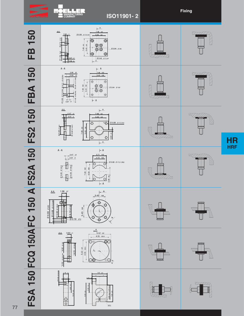
Fixing
77
ISO11901- 2
S = rod section areaP = nominal charging pressure
F0 = nominal initial forceF1 = average final force V0 = volume of gas
������ Ø 100�
����� 190�
����� 138
�����
138
������
190�
�����
Ø 2
6���� ��
���� �
������� 25
A
A
A - A
������
Ø 1
7,5
������� �������
Ø 1
8
���� ��
������
Ø
��� ��
������� 15
FBA
150
���� 8
�������� Ø 17,5 (4x)�
������
24�
�����
190��
�������
138��
���� 190��
������ 138�
����� 12
�������Ø
150
,5
�������Ø
143
,5�
�
�
� �
FS2
150
������� � Ø 17,5 ��� �
����
60���� �
190���
�����
165�
���� � 145�
��� � 120
���� � 12�
�������
Ø 1
50,5�
�������
Ø 1
43,5�
���� � 8
A
A
A - A
FS2A
150
���� 25
�������� Ø 17,5 (4x)
�������� Ø 11 (4x)�
������� 190
�������� 138
������
138�
������
190�
�������
Ø 1
8�
������ 15
��
��
����
�������� Ø 100
����� ��
Ø 2
6�
����� 17FB15
0
������ 138�
��������Ø
150
,5��
������� Ø 5
�������
Ø 1
7,5
(4x)
�
������
Ø 2
20�
= =
����� 27�
������Ø
155
��
��
����
������
138�����
FC15
0A
= =
A A
A
A
¯4.
92Ø
125
¯0.
53Ø
13,5
(4x)
¯4.
74Ø
120,
5
0.83 21
5.12
130
4.31
109.
5
5.12 130
4.31 109.5
FCQ
150A
���
������
230�
����
110�
����� 30
� �
�������
260�
������
125�
����� 200�
����
������ 20
������
Ø 1
3,5
(2x)�
�����
200������
95�
� �����Ø
150
�����
91,5�
FSA
150
HRHRF

LILI GENERAL INFORMATION
78
BODY-One piece construction for greater safety-Internal surface burnished for maximum efficiency of static O-Ring -Black oxided
ROD-One piece construction for greater safety-Nitrided surface with hardness ab. 1200 HV for maximum durability, no wearing for optimum life of seal-Lapped surface “mirror like” with roughness Ra � 0,05µ for maximum performances, smoothest fric-tion, lower over all temperature, longer lasting and less wear to the seal
BUSHING / GUIDE & SEAL-One piece construction-Two non-metallic self-lubricating guide elements for lower friction, longer lasting and minimize side loading
-Wiper rod to protect inside room from contaminants-Polyurethane dynamic rod seal-C-style retaining ring ensures operator safety and prevents from opening a charged cylinder-Designed and built for easy, rapid and inexpensive maintenance
USE -Self contained-Hose system: for this application the cylinders are easily converted by removing the protective screw,locking nut and one way valve (except LI 400 subjected to supply a specific .39” higher body)
LOADING PRESSURE-Minimum allowed 290 psi (20 bar) -Maximum allowed 2900 psi (200 bar) -For hose applications it is suggested to calculate the forces by charging at about 1450 psi (150 bar).In this case the user can adjust the required force by increasing charging pressure up to the maximumallowed of 2175 psi (200 bar) anytime
SPEED - LIFETIME-The maximum recommended speed (cycles/minute) and the minimum estimated life are easily indicatedby specific graphs for each model

ØD
inch mm
Series
LI 400LI 900LI 1400LI 2000LI 3200
1.77
2.48
2.95
3.74
4.72
45
63
75
95
120
Cu
0.51 - 3.94
0.98 - 4.92
0.98 - 4.92
0.98 - 4.92
0.98 - 4.92
13 - 100
25 - 125
25 - 125
25 - 125
25 - 125
inch mm
L
inch mm
2.28 - 9.13
3.70 - 11.57
3.74 - 11.61
4.53 - 12.40
4.92 - 12.80
58 - 232
94 - 294
95 - 295
115 - 315
125 - 325
F0
900
2027
3175
4583
7162
400
900
1410
2035
3180
lb. daN
8082848688
Page
79
one piece rod
self-lubricatingguide elements
bushing
retaining ring
one piece body
rod seal
O-Ring seal
one way valvecharging hole plug nut
rod wiper
LI

LI 400
�
O r d e r i n g e x a m p l e :
(10) LI 400 - 50
in.3 cm3
CodeCu L Lmin S V0F0 F1
0.51
0.98
1.26
1.50
1.97
2.48
3.15
3.94
13
25
32
38
50
63
80
100
2.28
3.29
3.78
4.25
5.20
6.22
7.56
9.13
58
82
96
108
132
158
192
232
0.32 2,01 2900 200 900 400 1210 537
inch mm inch mm inch mm in.2 cm2 psi bar lb. daN lb. daN
LI 400 - 013LI 400 - 025LI 400 - 032LI 400 - 038LI 400 - 050LI 400 - 063LI 400 - 080LI 400 - 100
P
1.77
2.24
2.52
2.76
3.29
3.74
4.41
5.20
45
57
64
70
82
95
112
132
0.95
1.10
1.21
1.28
1.43
1.59
1.83
2.07
0,43
0,50
0,55
0,58
0,65
0,72
0,83
0,94
Weight
~ lb. ~ Kg
-
-
-
-
-
-
-
-
-
-
-
-
-
-
-
-
-
-
-
-
-
-
-
-
80“All dimensions are nominal unless tolerance is stated”
(±5%)
0
0.5
1
1.5
2
2.5
3
3.5
4
0 .51 .98 1.5 1.97 2.48 3.15 3.94 0
20
40
60
80
100
120
140
160
1.26
400
420
440
460
480
540
560
900
945
990
450
1035
1215
1260
5201170
5001125
.51 .98 1.26 1.5 1.97 2.48 3.15 3.94
Cu (inch)
Cyc
les
/m
in.
Cyc
les
(inm
illio
ns)
Force (lbs. daN) / stroke (inch) diagram
For
ce(lb
s.da
N)
Cu (inch)
Minimum estimated life (cycles x millions) Maximum recommended speed (cycles / min.)

���
��
���������
±0,2
5
�� ���������������
����1
0
Fixing
�������� Ø 9 (2x)�
�������� Ø 9�
������ 70�
����� 50�
������
50�
�������
70��
��������Ø 20�������Ø
15
(2x)�
������ 12�
�������� 20
������ 14
��
��
����
������Ø
15
(4x)�
�������� Ø 11�
FB45
�������� Ø 9 (4x)�
������
20�
�����
70�
�������
50�
����� 70�
������ 50
������ 7�
����Ø
41,
5�
�� 4
��
��
����
������Ø
45,
5
FS2
45
FBA
45
������������
60�������
�������Ø
90
A
A
��������
��������������
A - A
��� � 34�������
���� � 60�������
�������
Ø 9����
����� � 16��
���� � 8��
������� ��� ��� = �����������
�������
Ø 1
4����
FC45
A
81
ISO11901- 2
FCQ
45A
FS2A
45
����� � Ø 20�
����� � 70�
����� � 50
������7
0�
������5
0
�������Ø
15�����
�������Ø
18����
����� � ��
������� �20
����� � 14
A
A
A - A
����� �Ø
11�����
���� ��Ø
9����
�����
25�
�����
70���
�����
57�
�� � 40�
��� � 27
���� � 7�
������
Ø 4
5,5�
������
Ø 4
1,5�
��� � 4
A
A
A - A
����� � Ø 9 ��� ��� �
= =
A A
A
A
¯1.
85Ø
47¯
0.35
Ø9
(4x) ¯
1.79
Ø45
,5 0.51 13
2.52
64
1.97
50
2.52 64
1.97 50
The LI 400 - ...N are non self-containingcylinders with the same stroke as the LI 400but with the lengths L and Lmin increased of10 mm
Ordering example: (10) LI 400 - 50 N
Non self-containing cylindersLI 400 - ... N
LI

LI 900
O r d e r i n g e x a m p l e :
(10) LI 900 - 50
in.3 cm3
CodeCu L Lmin S V0F0 F1
0.98
1.26
1.50
1.97
2.48
3.15
3.94
4.92
25
32
38
50
63
80
100
125
3.70
4.25
4.72
5.67
6.69
8.03
9.61
11.57
94
108
120
144
170
204
244
294
0.70 4,52 2900 200 2027 900 2714 1205
inch mm inch mm inch mm in.2 cm2 psi bar lb. daN lb. daN
LI 900 - 025LI 900 - 032LI 900 - 038LI 900 - 050LI 900 - 063LI 900 - 080LI 900 - 100LI 900 - 125
P
2.72
2.99
3.23
3.70
4.21
4.88
5.67
6.65
69
76
82
94
107
124
144
169
2.56
2.74
2.87
3.20
3.53
3.97
4.48
5.16
1,16
1,24
1,30
1,45
1,60
1,80
2,03
2,34
Weight
~ lb. ~ Kg
1.49
2.36
3.17
4.72
6.40
8.63
11.3
14.6
24
38
51
76
103
139
182
235
82“All dimensions are nominal unless tolerance is stated”
(±5%)
0
0.4
0.8
1.2
1.6
2.0
2.4
2.8
3.2
0
40
80
120
160
200
240
280
320
.98 1.50 2.48 3.15 3.94 4.92 1.26 1.97
.98 1.50 1.97 2.48 3.15 3.94 4.92 900
950
1000
1050
1100
1250
1300
2025
2137.5
2250
2362.5
2475
2812.5
2925
12002700
11502587.5
1.26
Cu (inch)
Cyc
les
/m
in.
Cyc
les
(inm
illio
ns)
Force (lbs. daN) / stroke (inch) diagram
For
ce(lb
s.da
N)
Cu (inch)
Minimum estimated life (cycles x millions) Maximum recommended speed (cycles / min.)

Fixing
83
ISO11901- 2
�������� Ø 9 (2x)�
�������� 75��
��������� 56,5�
���������
56,5�
��������
75�
���������Ø 20��������
Ø 1
5��������
Ø 1
5�
������ 12
���� 20
������� 14
�
�
��
�������� Ø 9�
������� Ø 11�
FB50
Ø 0,
43 Ø
11 (
4x)
0,94 24
3,3
5 85
2,,5
63,5
3,35 85 2,5 63,5
0,47 12
Ø 0,
31 Ø
63,
5
Ø 2,
26 Ø
57,
5
0,31 8
A
A
A - A
FS2
63
FBA
50
������ 73,5�
���������
Ø 6
3,5��
������� Ø 4�
��������
Ø 1
1�� ��
�������
Ø 1
22�
= =
������� 16�
�������Ø
67
��
��
����
������
73,5�����
FC63
A
FS2A
63
������ �Ø 20�
����� � 75�
����� � 56,5
������7
5�
������5
6,5
�������Ø
15�����
�������Ø
18�����
����� � ��
������� �20
����� � 14
A
A
A - A
����� �Ø
11�����
���� ��Ø
9����
������ � Ø 11 ���� ���� �
��
30�
��� �
75���
�����
62�
��� � 58�
�� � 42
���� � 12�
���� ��
Ø 6
3,5�
�������
Ø 5
7,5�
��� � 8
A
A
A - A
LI

LI 1400
O r d e r i n g e x a m p l e :
(10) LI 1400 - 50
in.3 cm3
CodeCu L Lmin S V0F0 F1
0.98
1.26
1.50
1.97
2.48
3.15
3.94
4.92
25
32
38
50
63
80
100
125
3.74
4.29
4.76
5.71
6.73
8.07
9.64
11.61
95
109
121
145
171
205
245
295
1.09 7,07 2900 200 3175 1410 4308 1913
inch mm inch mm inch mm in.2 cm2 psi bar lb. daN lb. daN
LI 1400 - 025LI 1400 - 032LI 1400 - 038LI 1400 - 050LI 1400 - 063LI 1400 - 080LI 1400 - 100LI 1400 - 125
P
2.76
3.03
3.27
3.74
4.25
4.92
5.71
6.69
70
77
83
95
108
125
145
170
3.56
3.83
4.03
4.33
4.84
5.76
6.09
7.19
1,62
1,74
1,83
1,99
2,20
2,62
2,77
3,27
Weight
~ lb. ~ Kg
5.78
7.14
8.32
10.8
13.2
16.5
20.4
25.3
93
115
134
172
213
266
329
408
84“All dimensions are nominal unless tolerance is stated”
(±5%)
0
0.5
1
1.5
2
3
2.5
0
40
80
120
160
200
240
.98 1.50 2.48 3.15 3.94 4.92 1.26 1.97
1410
1510
1610
1710
1910
2010
3175
3400
3625
3850
4300
4525
18104075
.98 1.50 1.97 2.48 3.15 3.94 4.92 1.26
Cu (inch)
Cyc
les
/m
in.
Cyc
les
(inm
illio
ns)
Force (lbs. daN) / stroke (inch) diagram
For
ce(lb
s.da
N)
Cu (inch)
Minimum estimated life (cycles x millions) Maximum recommended speed (cycles / min.)

Fixing
���� 20
�������� Ø 11 (4x)�
������� Ø 9 (4x)
��������� 100�
������� 73,5���
��������
73,5����
��������
100�
�������Ø
15
(4x)�
�������Ø
18
(4x)��
����� 12�
������� 14�
��
��
����
� ������ Ø 40�
FB75
�������� Ø 11 (4x)�
������
24�������
100��
�������
73,5�
������ 100�
������� 73,5
����� 12�
������Ø
75,
5�
�����Ø
68,
5
���� 8
�
�
��
FS2
75
������ Ø 40�
����� 100�
��� 73,5
���
73,5
������
100�
�������
Ø 1
8���� ��
����� 12
�������� 20
A
A
A - A
�������
Ø 1
1���� ���������
Ø 1
5���� ��
�������
Ø 9
���� ��
�������� 14
FBA
75
������� � Ø 11 ���� ���� �
��
30�
�����
100���
����
84�
�� � � 70�
��� � 54
��� � 12�
����� �
Ø 7
5,5�
���� ��
Ø 6
8,5�
��� � 8
A
A
A - A
������� 73,5����
��������Ø
75,
5�
������� Ø 5�
�������Ø
11 (
4x)
�
������
Ø12
2�
= =
������ 16
����� �Ø
80
��
��
����
�������
73,5�����
FC75
A = =
A A
A
A
¯3.
15Ø
80¯
0.43
Ø11
(4x) ¯
2.97
Ø75
,5
0.63 16
3.54
90
2.89
73,5
3.54 90
2.89 73,5
85
ISO11901- 2
FCQ
75A
FS2A
75
����
������
137�
�����
63,5�
����� 30
�����
160�
������
75�
������ 105�
��
�� ��� 20
��������
Ø 1
1 (2
x)�
������
115���� ��
52,5�
��������Ø
75
��� ��
50�
FSA
75
LI

LI 2000
O r d e r i n g e x a m p l e :
(10) LI 2000 - 50
in.3 cm3
CodeCu L Lmin S V0F0 F1
0.98
1.26
1.50
1.97
2.48
3.15
3.94
4.92
25
32
38
50
63
80
100
125
4.53
5.08
5.55
6.50
7.52
8.86
10.43
12.40
115
129
141
165
191
225
265
315
1.58 10,18 2900 200 4583 2035 5750 2553
inch mm inch mm inch mm in.2 cm2 psi bar lb. daN lb. daN
LI 2000 - 025LI 2000 - 032LI 2000 - 038LI 2000 - 050LI 2000 - 063LI 2000 - 080LI 2000 - 100LI 2000 - 125
P
3.54
3.82
4.05
4.53
5.04
5.71
6.50
7.48
90
97
103
115
128
145
165
190
7.26
7.72
8.00
8.59
9.36
10.6
11.4
12.8
3,29
3,50
3,62
3,89
4,24
4,78
5,16
5,82
Weight
~ lb. ~ Kg
12.9
15.0
16.9
20.6
24.6
29.8
36.0
43.7
208
242
272
332
396
480
579
703
86“All dimensions are nominal unless tolerance is stated”
(±5%)
0
0.5
1
1.5
2
2.5
3
.98 1.50 2.48 3.15 3.94 4.92 1.2 1.97
0
40
80
120
160
200
240
2035
2135
2235
2335
2635
2735
4583
4808
5033
5258
5933
6158
25355708
24355483
.98 1.50 1.97 2.48 3.15 3.94 4.92 1.26
Cu (inch)
Cyc
les
/m
in.
Cyc
les
(inm
illio
ns)
Force (lbs. daN) / stroke (inch) diagram
For
ce(lb
s.da
N)
Cu (inch)
Minimum estimated life (cycles x millions) Maximum recommended speed (cycles / min.)

Fixing
�������� Ø 13,5 (4x)
�������� Ø 9 (4x)
������ 120�
����� 92
�������
92��
�������
120��
�������
Ø 1
5 (4
x)��
������� 14
��
��
����
������� Ø 60
��� 20
�������
Ø 2
0 (4
x)�
������� 13
FB95
������������ 8
0-0.1
�������
Ø 1
3�����
24�
�������
120�
���� ���
92,0
������ 120�
��� ��� 92,0�
������ 12�
����� �Ø
95,
5�
�������Ø
88,
5
��
��
����
FS2
95
������ Ø 60�
����� 120�
����� 92
�����
92
������
120�
������
Ø 2
0������
�� �� 13
������� 20
A
A
A - A
���� ��
Ø 1
3,5
���������
���� �
Ø 1
5������
����� �
Ø 9
������
����� � 14
FBA
95
������� � Ø 13,5 ��� �
����
40�
�����
120���
�� ��
100�
���� � 90�
���� � 70
���� � 12�
�������
Ø 9
5,5�
�������
Ø 8
8,5�
��� � 8
A
A
A - A
������ 92��
��������Ø
95,
5��
������� Ø 5�
������
Ø 1
3 (4
x)�
������
Ø15
0�
= =
������ 18�
��������Ø
100�
�
�
� �
�������
92�����
FC95
A = =
A A
A
A
¯3.
94Ø
100
¯0.
51Ø
13(4
x) ¯3.
76Ø
95,5
0.71 18
4.33
110
3.62
92
4.33 110
3.62 92
87
ISO11901- 2
FCQ
95A
FS2A
95
����
������
170� ������
80�
����� 30
�����
195�
������
92,5�
������ 125�
��
����� 20
�� �����
Ø 1
3,5
(2x)�
������
145�
�������
67,5�
��������Ø
95
�������
62,5�
FSA
95
LI

LI 3200
O r d e r i n g e x a m p l e :
(10) LI 3200 - 50
in.3 cm3
CodeCu L Lmin S V0F0 F1
0.98
1.26
1.50
1.97
2.48
3.15
3.94
4.92
25
32
38
50
63
80
100
125
4.92
5.47
5.94
6.89
7.91
9.25
10.83
12.79
125
139
151
175
201
235
275
325
2.47 15,9 2900 200 7162 3180 8831 3921
inch mm inch mm inch mm in.2 cm2 psi bar lb. daN lb. daN
LI 3200 - 025LI 3200 - 032LI 3200 - 038LI 3200 - 050LI 3200 - 063LI 3200 - 080LI 3200 - 100LI 3200 - 125
P
3.94
4.21
4.49
4.92
5.43
6.10
6.89
7.87
100
107
113
125
138
155
175
200
10.46
12.38
14.30
15.38
16.47
18.12
19.73
22.25
4,74
5,61
6,48
6,97
7,46
8,21
8,94
10,08
Weight
~ lb. ~ Kg
20.8
24.1
27.0
32.7
38.9
46.9
56.5
68.3
343
398
445
539
641
774
932
1127
88“All dimensions are nominal unless tolerance is stated”
(±5%)
0
40
80
120
160
200
240
0
0.5
1
1.5
2
3
.98 1.50 2.48 3.15 3.94 4.921.26 1.97
2.5
3180
3280
3380
3480
3580
3980
4180
7162
7387
7612
7837
8062
8962
9412
38808737
37808512
36808287
40809187
.98 1.50 1.97 2.48 3.15 3.94 4.92 1.26
Cu (inch)
Cyc
les
/m
in.
Cyc
les
(inm
illio
ns)
Force (lbs. daN) / stroke (inch) diagram
For
ce(lb
s.da
N)
Cu (inch)
Minimum estimated life (cycles x millions) Maximum recommended speed (cycles / min.)

Fixing
����
�������� Ø 13,5 (4x)�
�������� Ø 11 (4x)�
������� 140�
�������� 109,5�
�������
109,
5��
������
140��
�������
Ø 1
8 (4
x)������� 15�
�
�
��
������� Ø 80�
20
��������
Ø 2
0 (4
x)
������ 13�FB12
0
���� 8
�������� Ø 13 (4x)�
�����
24�
������
140�
�����
109,
5��
������ 140�
����� 109,5�
���� 12�
����Ø
120
,5
����Ø
113
,5
��
��
����
FS2
120
������ Ø 80�
����� 140�
����� 109,5
�����
109,
5
������
140�
������
Ø 2
0������
����� ��
������� 20
A
A
A - A
�������
Ø 1
3,5
����������������
Ø 1
8
������
�������
Ø
�������
������� 15
FBA
120
������� � Ø 13,5 ��� �
����
50�
����
140���
��� �
120�
���� � 115�
��� � 95
���� � 12�
�������
Ø 1
20,5�
�������
Ø 1
13,5�
��� � 8
A
A
A - A
������ 109,5�����
��������Ø
120
,5���
������� Ø 5
��������
Ø 1
3,5
(4x)
�
���� ��
Ø 1
75�
= =
������� 21
����� ��Ø
125�
��
��
����
�������
109,
5�����
FC12
0A
= =
A A
A
A
¯4.
92Ø
125
¯0.
53Ø
13,5
(4x) ¯
4.74
Ø12
0,5
0.83 21
5.12
130
4.31
109.
5
5.12 130
4.31 109.5
89
ISO11901- 2
FCQ
120
AFS
2A12
0
����
������
195�
�����
92,5�
������ 30
������
220�
�����
105�
������ 148�
��
��� �� 20
��������
Ø 1
3,5
(2x)
�
�� ��
165�������
77,5�
�������
Ø 120
�� ���
74�
FSA
120
LI

KK GENERAL INFORMATION
BODY-Internal surface burnished for maximum efficiency of static O-Ring-Nitrided surface with hardness ab. 800 HV for maximum durability, no wearing for optimum life of seal-Lapped surface “mirror like” with roughness Ra � 0,05µ for maximum performances, smoothest fric-tion, lower over temperature, longer lasting and less wear to the seal-Black oxided
ROD
-One piece construction for greater safety-Nitrided surface-Ground and polished surface
GUIDE & SEAL-Two non-metallic self-lubricating guide elements for lower friction, longer lasting and minimized side loading
-Wiper rod to protect inside room from contaminants-Polyurethane dynamic piston seal-C-style retaining ring to ensures operator best safety and prevents from opening a charged cylinder-Designed and built for easy, rapid and inexpensive maintenance
USE -Self contained-Hose system: subjected to supply a specific .79” (20mm) higher body
LOADING PRESSURE-Minimum allowed 290 psi (20 bar) -Maximum allowed 2175 psi (150 bar) -For hose applications it is suggested to calculate the forces by charging at about 1450 psi (100 bar).In this case the user can adjust the required force by increasing charging pressure up to the maximumallowed of 2175 psi (150 bar) anytime
SPEED - LIFETIME-The maximum recommended speed (cycles/minute) and the minimum estimated life are easily indicatedby specific graphs for each model
90

ØD
inch mm
Series
K 40K 75
K 100K 180K 470K 750
K 1200K 1830
0.98
1.26
1.50
1.97
2.95
3.74
4.72
5.90
25
32
38
50
75
95
120
150
0.39 - 1.97
0.39 - 1.97
0.24 - 1.97
0.24 - 1.97
0.39 - 1.97
0.39 - 1.97
0.39 - 1.97
0.39 - 1.97
10 - 50
10 - 50
6 - 50
6 - 50
10 - 50
10 - 50
10 - 50
10 - 50
inch mm
L
inch mm
2.95 - 7.68
2.95 - 7.68
2.40 - 9.06
2.60 - 8.66
3.15 - 9.45
3.54 - 10.04
3.94 - 10.24
4.33 - 10.62
75 - 195
75 - 195
61 - 230
66 - 220
80 - 240
90 - 255
100 - 260
110 - 270
F0
956
1665
2385
4241
10520
16965
26505
41422
425
740
1060
1885
4675
7540
11780
18410
lb. daN
9293949698100102104
Page
one piece rod
retaining ring
O-Ring seal
charging hole plug
ball
O-Ring seal
rod wiper
spring
bodyself-lubricatingguide elements
plug
end plate
rod seal
91
Cu
K

K 40
������������
��
���� ��
������
1
�������������
0,25
�������� Ø 12
�������� Ø 14
��
������ ����� Ø 25 0,3
����������������
O r d e r i n g e x a m p l e :
(10) K 40 - 50
CodeCu L Lmin S F0 F1
0.39
0.59
0.98
1.97
10
15
25
50
2.95
3.54
4.72
7.68
75
90
120
195
0.44 2,83 2175 150 956 425 1924 855
inch mm inch mm inch mm in.2 cm2 psi bar lb. daN lb. daN
P Weight
~ lb. ~ Kg
2.56
2.95
3.74
5.71
65
75
95
145
0.40
0.44
0.53
0.77
0,18
0,20
0,24
0,35
K 40 - 010
K 40 - 015
K 40 - 025
K 40 - 050
---
---
---
---
�
���
�
���
�
���
�
��
��
��
��
��
��
��
�
� �� �� � ���
425
525
625
725
825
925
1025
���
����
����
����
����
����
����
���������
Cu (inch)
Cyc
les
/min
.
Cyc
les
(inm
illio
ns)
Force (lbs. daN) / stroke (inch) diagram
For
ce(lb
s.da
N)
Cu (inch)
Minimum estimated life (cycles x millions) Maximum recommended speed (cycles / min.)
92
S = piston section areaP = nominal charging pressureF0 = nominal initial forceF1 = average final force
“All dimensions are nominal unless tolerance is stated”
(±5%)

K 75
Ø 32 ±0,3������ �����
�
������� Ø 19
�������� Ø 15
��� ��
1
������
���
����������
�����
±0,2
5
��������
���������������
O r d e r i n g e x a m p l e :
(10) K 75 - 50
CodeCu L Lmin S F0 F1
0.39
0.59
0.98
1.97
10
15
25
50
2.95
3.54
4.72
7.68
75
90
120
195
0.75 4,91 2175 150 1665 740 3600 1 600
inch mm inch mm inch mm in.2 cm2 psi bar lb. daN lb. daN
P Weight
~ lb. ~ Kg
2.56
2.95
3.74
5.71
65
75
95
145
0.66
0.71
0.86
1.26
0,30
0,32
0,39
0,57
K 75 - 010
K 75 - 015
K 75 - 025
K 75 - 050
---
---
---
---
�
���
�
���
�
���
�
��
��
��
��
��
��
��
�
� �� �� � ���
740
940
1140
1340
1540
1740
1940
1665
2115
2565
3015
3465
3915
4365
.39 .59 .98 1.97
93
Cu (inch)
Cyc
les
/min
.
Cyc
les
(inm
illio
ns)
Force (lbs. daN) / stroke (inch) diagram
For
ce(lb
s.da
N)
Cu (inch)
Minimum estimated life (cycles x millions) Maximum recommended speed (cycles / min.)
S = piston section areaP = nominal charging pressureF0 = nominal initial forceF1 = average final force
“All dimensions are nominal unless tolerance is stated”
(±5%)
K

K 100
��
���
��1
��
���
��1
������ ����� Ø 38 �0,3
������� Ø 36
������� Ø 36
�
����� �� Ø 20
���
���
10,5
�������� Ø 17
���
�����
���
��0,
25
���
���
���
��
���������
���������������� !
��"
��9
,5
���
���
1
O r d e r i n g e x a m p l e :
(10) K 100 - 50
CodeCu L Lmin S F0 F1
0.24
0.39
0.63
0.98
1.26
1.57
1.97
6
10
16
25
32
40
50
2.40
2.95
3.94
5.31
6.57
7.68
9.06
61
75
100
135
167
195
230
1.09 7,06 2175 150 23851 06040731 810
inch mm inch mm inch mm in.2 cm2 psi bar lb. daN lb. daN
P Weight
~ lb. ~ Kg
2.17
2.56
3.31
4.33
5.31
6.10
7.09
55
65
84
110
135
155
180
0.80
0.91
1.06
1.28
1.37
1.50
1.63
0,36
0,41
0,48
0,58
0,62
0,68
0,74
K 100 - 006K 100 - 010K 100 - 016K 100 - 025K 100 - 032K 100 - 040K 100 - 050
�
���
���
���
���
���
���
���
�
��
��
��
��
��
��
�
��
� ��� �� ��� �� ������ ���
���
1060
1260
1460
1660
1860
2060
2260
2385
2835
3385
3735
4185
4635
5085
.24 .39 .63 .98 1.26 1.57 1.97
Cu (inch)
Cyc
les
/min
.
Cyc
les
(inm
illio
ns)
Force (lbs. daN) / stroke (inch) diagram
For
ce(lb
s.da
N)
Cu (inch)
Minimum estimated life (cycles x millions) Maximum recommended speed (cycles / min.)
94
S = piston section areaP = nominal charging pressureF0 = nominal initial forceF1 = average final force
“All dimensions are nominal unless tolerance is stated”
in.3 cm3
0.68
1.12
2.05
3.29
4.47
5.40
6.65
11
18
33
53
72
87
107
V0
(±5%)
---------------------

Fixing
������ 40�����
��������Ø
38,
5��
�������� Ø 2�
�������
Ø 6
,6 (
4x)
�
������
Ø 6
8� = =
������� 9�
��������Ø
40
��
��
����
������
40�����
FC38
A
= =
A A
A
A
¯1.
57Ø
40¯
0.26
Ø6,
6(4
x) ¯1.
52Ø
38,5
0.35 9
2.05
52
1.57
40
2.05 52
1.57 40
FCQ
38A
95
������
������
���
���� ��
������
�����1
0,5
������
20
�����4
�����3
.5
������� Ø 33
������������������
Non self-containing cylinders
O r d e r i n g e x a m p l e :
(10) K 100 - 50 N
CodeCu L Lmin
0.24
0.39
0.63
0.98
1.26
1.57
1.97
6
10
16
25
32
40
50
3.19
3.74
4.72
6.10
7.36
8.46
9.84
81
95
120
155
187
215
250
inch mm inch mm inch mm
2.95
3.35
4.09
5.12
6.10
6.89
7.87
75
85
104
130
155
175
200
K 100 - 006NK 100 - 010NK 100 - 016NK 100 - 025NK 100 - 032NK 100 - 040NK 100 - 050N
K 100 - ... N
ISO11901- 2
��������
Ø 7�
�����
5��������
55��
������
40�
������ 55�
������ 40�
������ 7�
�������Ø
38,
5
������Ø
34,
5�
�������������� 4 0-0.1
�������
��
��
����
FS2
38
K

K 180
����
���
2�
���
���
2
����� ���� Ø 50 0,3
�������� Ø 46
�������� Ø 46
��
�������� Ø 30
���
��
14,5
����� �� Ø 26
������
���
���
0,25
���
���
���
��
�����������
������������������
���
!�1
3,5
���
"��
1
O r d e r i n g e x a m p l e :
(10) K 180 - 50
CodeCu L Lmin
0.24
0.39
0.63
0.98
1.26
1.57
1.97
6
10
16
25
32
40
50
2.60
3.15
4.17
5.31
6.38
7.48
8.66
66
80
106
135
162
190
220
inch mm inch mm inch mm
2.36
2.76
3.54
4.33
5.12
5.91
6.69
60
70
90
110
130
150
170
K 180 - 006K 180 - 010K 180 - 016K 180 - 025K 180 - 032K 180 - 040K 180 - 050
�
���
���
���
���
���
���
���
�
��
��
��
��
��
��
�
��
� ��� �� ��� �� ������ ���
���
1885
2085
2285
2485
2685
2885
3085
3285
3485
4241
4691
5141
5591
6041
6491
6941
7391
7841
.24 .39 .63 .98 1.26 1.57 1.97
Cu (inch)
Cyc
les
/min
.
Cyc
les
(inm
illio
ns)
Force (lbs. daN) / stroke (inch) diagram
For
ce(lb
s.da
N)
Cu (inch)
Minimum estimated life (cycles x millions) Maximum recommended speed (cycles / min.)
96
S = piston section areaP = nominal charging pressureF0 = nominal initial forceF1 = average final force
“All dimensions are nominal unless tolerance is stated”
S F0 F1
1.94 12,572175 150 4241 1885 7000 3110
in.2 cm2 psi bar lb. daN lb. daN
P Weight
~ lb. ~ Kg
1.57
1.72
2.01
2.30
2.47
2.67
2.94
0,71
0,78
0,91
1,04
1,12
1,21
1,33
in.3 cm3
1.43
2.30
3.97
5.77
7.51
7.51
11.1
23
37
64
93
121
148
179
V0
(±5%)
---------------------

��������������� �� Ø 26
������
���
��
����� �
�����
����1
0,5
������
20
����8
�� �5
������ Ø 43
������������������
Fixing
������ 56,5����
��������Ø
50,
5�
�������� Ø 4�
�������
Ø 9
(4x
)�
�������
Ø 9
5� = =
������ 13
��������Ø
54�
�
�
� �
������
56,5�����
FC50
A = =
A A
A
A
¯2.
13Ø
54¯
0.35
Ø9
(4x) ¯
1.99
Ø50
,5
0.51 13
2.75
70
2.22
56,5
2.75 70
2.22 56,5
FCQ
50���
������
110� ������
50�
������ 30
�����
130�
������
60�
������ 80�
��
����� 20
�� ����
Ø 9
(2x
)�
�����
90�
������
40�
��������Ø
50
�������
37,5�
FSA
50
Non self-containing cylinders
CodeCu L Lmin
0.24
0.39
0.63
0.98
1.26
1.57
1.97
6
10
16
25
32
40
50
3.38
3.94
4.96
6.10
7.17
8.27
9.45
86
100
126
155
182
210
240
inch mm inch mm inch mm
3.15
3.54
4.33
5.12
5.91
6.69
7.48
80
90
110
130
150
170
190
K 180 - 006NK 180 - 010NK 180 - 016NK 180 - 025NK 180 - 032NK 180 - 040NK 180 - 050N
K 180 - ... N
97
ISO11901- 2
O r d e r i n g e x a m p l e : (10) K 180 - 50 N
������ � Ø 9 ������ �
����
25�
����
75���
�����
62�
��� � 45�
��� � 32
���� � 12�
�� ��
Ø 5
0,5�
�� ����
Ø 4
4,5�
��� � 8
A
A
A - A
������
24�
������
75�
������
56,5��
������ 75
������ 56,5
������ 12�
������Ø
50,
5
������Ø
44,
5
���������� 8
0-0.1
��
��
����
�������
Ø 9�
FS2A
50FS
250
K

�
���
���
���
���
���
�
�
��
��
��
��
��
��
��
��
��
� �� ��� �� ������ ���
���
K 470
����
��2,
5�
���
��2,
5
���
����
��
��������
�����
±0,2
5
���� ��� Ø 40
���
���
18�
���
���
17
�������� Ø 50
��
�������� Ø 70
�������� Ø 70
����� ����� Ø 75 ±0,3
����������
�����������������
���
���
1
O r d e r i n g e x a m p l e :
(10) K 470 - 50
in.3 cm3
CodeCu L Lmin S V0F0 F1
0.39
0.63
0.98
1.26
1.57
1.97
10
16
25
32
40
50
3.15
4.17
5.31
6.57
7.87
9.45
80
106
135
167
200
240
4.81 31,16 2175 150 10520 4 675 17651 7 845
inch mm inch mm inch mm in.2 cm2 psi bar lb. daN lb. daN
K 470 - 010K 470 - 016K 470 - 025K 470 - 032K 470 - 040K 470 - 050
P
2.76
3.54
4.33
5.31
6.30
7.48
70
90
110
135
160
190
4.08
4.66
5.17
5.61
6.12
6.76
1,85
2,11
2,34
2,54
2,77
3,06
Weight
~ lb. ~ Kg
5.90
10.2
14.8
20.3
25.8
32.5
95
165
238
327
416
523
4675
5175
5675
6175
6675
7175
7675
8175
8675
�����
�����
�����
����
�����
�����
�����
����
����
������������������
Cu (inch)
Cyc
les
/min
.
Cyc
les
(inm
illio
ns)
Force (lbs. daN) / stroke (inch) diagram
For
ce(lb
s.da
N)
Cu (inch)
Minimum estimated life (cycles x millions) Maximum recommended speed (cycles / min.)
98
S = piston section areaP = nominal charging pressureF0 = nominal initial forceF1 = average final forceV0 = volume of gas
“All dimensions are nominal unless tolerance is stated”
(±5%)
------------------

Fixing
������� 73,5����
��������Ø
75,
5�
������� Ø 5�
�������Ø
11 (
4x)
�
������
Ø12
2� = =
������ 16
����� �Ø
80
��
��
����
�������
73,5�����
FC75
A
Non self-containing cylinders
������������������ Ø 40
��� ��
���
��
������
�����
����1
0,5
�����
20
����8
���5
������� Ø 67
������������������
CodeCu L Lmin
0.39
0.63
0.98
1.26
1.58
1.97
10
16
25
32
40
50
3.94
4.96
6.10
7.36
8.66
10.24
100
126
155
187
220
260
inch mm inch mm inch mm
3.54
4.33
5.12
6.10
7.09
8.26
90
110
130
155
180
210
K 470 - 010NK 470 - 016NK 470 - 025NK 470 - 032NK 470 - 040NK 470 - 050N
K 470 - ... N����
������
137�
�����
63,5�
����� 30
�����
160�
������
75�
������ 105�
��
�� ��� 20
��������
Ø 1
1 (2
x)�
������
115���� ��
52,5�
��������Ø
75
��� ��
50�
FSA
75 = =
A A
A
A
¯3.
15Ø
80¯
0.43
Ø11
(4x) ¯
2.97
Ø75
,5
0.63 16
3.54
90
2.89
73,5
3.54 90
2.89 73,5
FCQ
75A
99
ISO11901- 2
O r d e r i n g e x a m p l e : (10) K 470- 50 N
������� � Ø 1���
�����
30�
�����
100���
�����
84�
�� � 70�
��� � 54
��� � 12�
�����
Ø 7
5,5�
�����
Ø 6
8,5�
���� � 8
A
A
A - A
��������
Ø 1
1�������
24�������
100��
�������
73,5�
������ 100�
������� 73,5
����� 12�
������Ø
75,
5�
�����Ø
68,
5
����������� 8
0-0.1
��
��
����
FS2A
75FS
275
K
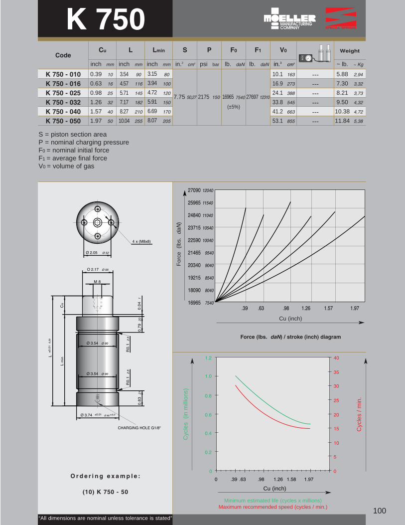
K 750
������
2,5
������
2,5
������ ���� Ø 95 0,3
������� Ø 90
������� Ø 90
��
������� Ø 55
������
21
������� Ø 52
������������
0,25
������
���
��
����������
���������� ��������
��� ��
20
������
1
O r d e r i n g e x a m p l e :
(10) K 750 - 50
in.3 cm3
CodeCu L Lmin S V0F0 F1
0.39
0.63
0.98
1.26
1.57
1.97
10
16
25
32
40
50
3.54
4.57
5.71
7.17
8.27
10.04
90
116
145
182
210
255
7.75 50,27 2175 150 16965 7540 27697 12310
inch mm inch mm inch mm in.2 cm2 psi bar lb. daN lb. daN
K 750 - 010K 750 - 016K 750 - 025K 750 - 032K 750 - 040K 750 - 050
P
3.15
3.94
4.72
5.91
6.69
8.07
80
100
120
150
170
205
5.88
7.30
8.21
9.50
10.38
11.84
2,94
3,32
3,73
4,32
4,72
5,38
Weight
~ lb. ~ Kg
10.1
16.9
24.1
33.8
41.2
53.1
163
273
388
545
663
855
�
���
���
���
���
���
�
�
��
��
��
��
��
��
��
� �� ��� �� ������ ����
���
7540
8040
8540
9040
9540
10040
10540
11040
11540
12040
�����
�����
�����
�����
�����
�����
����
�����
�����
����
�������������������
Cu (inch)
Cyc
les
/min
.
Cyc
les
(inm
illio
ns)
Force (lbs. daN) / stroke (inch) diagram
For
ce(lb
s.da
N)
Cu (inch)
Minimum estimated life (cycles x millions) Maximum recommended speed (cycles / min.)
100
S = piston section areaP = nominal charging pressureF0 = nominal initial forceF1 = average final forceV0 = volume of gas
“All dimensions are nominal unless tolerance is stated”
(±5%)
------------------

Fixing
������ 92��
��������Ø
95,
5��
������� Ø 5�
������
Ø 1
3 (4
x)�
������
Ø15
0� = =
������ 18�
��������Ø
100�
�
�
� �
�������
92�����
FC95
A
����
������
170� ������
80�
����� 30
�����
195�
������
92,5�
������ 125�
��
����� 20
�� �����
Ø 1
3,5
(2x)�
������
145�
�������
67,5�
��������Ø
95
�������
62,5�
= =
A A
A
A
¯3.
94Ø
100
¯0.
51Ø
13(4
x) ¯3.
76Ø
95,5
0.71 18
4.33
110
3.62
92
4.33 110
3.62 92
FSA
95
FCQ
95A
������������������ Ø 52
��� ��
���
��
������
������
���1
0,5
����
20
���8
��5
������� Ø 87
������������������
CodeCu L Lmin
0.39
0.63
0.98
1.26
1.57
1.97
10
16
25
32
40
50
4.33
5.35
6.50
7.95
9.06
10.83
110
136
165
202
230
275
inch mm inch mm inch mm
3.94
4.72
5.51
6.69
7.48
8.86
100
120
140
170
190
225
K 750 - 010NK 750 - 016NK 750 - 025NK 750 - 032NK 750 - 040NK 750 - 050N
Non self-containing cylindersK 750 - ... N
101
ISO11901- 2
O r d e r i n g e x a m p l e : (10) K 750- 50 N
������� � Ø 13
�����
40�
����
120���
����
100�
���� � 90�
��� � 70
���� � 12�
�������
Ø 9
5,5�
�������
Ø 8
8,5�
���� � 8
A
A
A - A
������������ 8
0-0.1
�������
Ø 1
3�����
24�
�������
120�
���� ���
92,0
������ 120�
��� ��� 92,0�
������ 12�
����� �Ø
95,
5�
�������Ø
88,
5
��
��
����
FS2A
95FS
295
K

K 1200
������
2,5
������
2,5
�����
����
�������������
±0,2
5
�� ����� Ø 68
������
22,5
�� ����� Ø 70
��
�������� Ø 115
�������� Ø 115
����� ����� Ø 120 ±0,3
������������
������������ ���!�"�
�����2
1,5
������
1
O r d e r i n g e x a m p l e :
(10) K1200 - 50
in.3 cm3
CodeCu L Lmin S V0F0 F1
0.39
0.63
0.98
1.26
1.57
1.97
10
16
25
32
40
50
3.94
4.96
6.10
7.36
8.66
10.24
100
126
155
187
220
260
12.17 78,50 2175 150 26505 11 780 42638 18 950
inch mm inch mm inch mm in.2 cm2 psi bar lb. daN lb. daN
K 1200 - 010K 1200 - 016K 1200 - 025K 1200 - 032K 1200 - 040K 1200 - 050
P
3.54
4.33
5.12
6.10
7.09
8.27
90
110
130
155
180
210
12.03
13.40
14.96
16.72
18.44
20.66
5,47
6,07
6,80
7,60
8,38
9,39
Weight
~ lb. ~ Kg
18.7
29.5
40.9
54.3
67.9
84.3
302
476
659
875
1094
1358
�
���
���
���
���
���
���
�
�
��
��
��
��
��
��
��
� �� ��� �� ������ ����
11780
12780
13780
14780
15780
16780
17780
18780
19780
26505
28755
31005
33255
35505
37755
40005
42255
44505
.39 .63 .98 1.26 1.57 1.97
Cu (inch)
Cyc
les
/min
.
Cyc
les
(inm
illio
ns)
Force (lbs. daN) / stroke (inch) diagram
For
ce(lb
s.da
N)
Cu (inch)
Minimum estimated life (cycles x millions) Maximum recommended speed (cycles / min.)
10
S = piston section areaP = nominal charging pressureF0 = nominal initial forceF1 = average final forceV0 = volume of gas
“All dimensions are nominal unless tolerance is stated”
(±5%)
------------------

Fixing
������ 109,5�����
��������Ø
120
,5���
������� Ø 5
��������
Ø 1
3,5
(4x)
�
���� ��
Ø 1
75�
= =
������� 21
����� ��Ø
125�
��
��
����
�������
109,
5�����
FC12
0A
����
������
195�
�����
92,5�
������ 30
������
220�
�����
105�
������ 148�
��
��� �� 20
��������
Ø 1
3,5
(2x)
�
�� ��
165�������
77,5�
�������
Ø 120
�� ���
74�
FSA
120
= =
A A
A
A
¯4.
92Ø
125
¯0.
53Ø
13,5
(4x) ¯
4.74
Ø12
0,5
0.83 21
5.12
130
4.31
109.
5
5.12 130
4.31 109.5
FCQ
120
A
������������
��� ��� Ø 68
�����
������
���
��
�������
������
�����1
0,5
������
20
�����8
����5
������� Ø 112
������������������
CodeCu L Lmin
0.39
0.63
0.98
1.26
1.57
1.97
10
16
25
32
40
50
4.72
5.75
6.89
8.15
9.45
11.02
120
146
175
207
240
280
inch mm inch mm inch mm
4.33
5.12
5.91
6.89
7.87
9.06
110
130
150
175
200
230
K 1200 - 010NK 1200 - 016NK 1200 - 025NK 1200 - 032NK 1200 - 040NK 1200 - 050N
Non self-containing cylindersK 1200 - ... N
10
ISO11901- 2
O r d e r i n g e x a m p l e : (10) K1200- 50 N
������� � Ø 13,5
����
50�
����
140���
��� �
120�
���� � 115�
��� � 95
���� � 12�
�������
Ø 1
20,5�
�������
Ø 1
13,5�
��� � 8
A
A
A - A
FS2A
120
������������ 8
0-0.1
�������
Ø 1
3������
24�
����
140�
������
109,
5��
���� 140�
������ 109,5�
������ 12�
�������Ø
120
,5
�������Ø
113
,5
��
��
����
FS2
120
K

K 1830
��
����
2,5
��
����
2,5
���
����
��
���
�����
���
��±0
,25
�� ���� Ø 90
���
���
24,5
�� ����� Ø 100
��
�������� Ø 145
�������� Ø 145
����� ����� Ø 150 ±0,3
�����������
���������������� �!�
���
"�2
3,5
���
���
1
O r d e r i n g e x a m p l e :
(10) K1830 - 50
in.3 cm3
CodeCu L Lmin S V0F0 F1
0.39
0.63
0.98
1.26
1.57
1.97
10
16
25
32
40
50
4.33
5.35
6.50
7.75
9.25
10.62
110
136
165
197
235
270
19.03 122.7 2175 150 41422 18 410 61380 27280
inch mm inch mm inch mm in.2 cm2 psi bar lb. daN lb. daN
K 1830 - 010K 1830 - 016K 1830 - 025K 1830 - 032K 1830 - 040K 1830 - 050
P
3.94
4.72
5.51
6.50
7.68
8.66
100
120
140
165
195
220
20.3
22.9
25.8
28,9
30,2
36,2
9,20
10,4
11,7
13,1
13,7
16,4
Weight
~ lb. ~ Kg
34.4
51.7
70.0
91.4
117
139
555
832
1127
1471
1889
2244
�
���
���
���
���
���
�
�
��
��
��
��
��
��
��
� �� ��� �� ������ ����
���
18410
20410
22410
24410
26410
28410
30410
32410
34410
41422
42922
50422
54922
59422
63922
68422
72922
77422
.39 .63 .98 1.26 1.57 1.97
Cu (inch)
Cyc
les
/min
.
Cyc
les
(inm
illio
ns)
Force (lbs. daN) / stroke (inch) diagram
For
ce(lb
s.da
N)
Cu (inch)
Minimum estimated life (cycles x millions) Maximum recommended speed (cycles / min.)
10
S = piston section areaP = nominal charging pressureF0 = nominal initial forceF1 = average final forceV0 = volume of gas
“All dimensions are nominal unless tolerance is stated”
(±5%)

Fixing
������ 138�
��������Ø
150
,5��
������� Ø 5
�������
Ø 1
7,5
(4x)
�
������
Ø 2
20�
= =
����� 27�
������Ø
155
��
��
����
������
138�����
FC15
0A
���
������
230�
����
110�
����� 30
� �
�������
260�
������
125�
����� 200�
����
������ 20
������
Ø 1
3,5
(2x)�
�����
200������
95�
� �����Ø
150
�����
91,5�
FSA
150
= =
A A A
A
¯6.
10Ø
155
¯0.
69Ø
17,5
(4x) ¯
5.93
Ø15
0,5
1.06 27
6.38
162
5.43
138
6.38 162
5.43 138
FCQ
150
A
����������������� Ø 90
�����������������
���
������
���
��
����� �
������
�����1
0,5
������
20
����8
�� ���
7
������� Ø 142
���
CodeCu L Lmin
0.39
0.63
0.98
1.26
1.57
1.97
10
16
25
32
40
50
5.12
6.14
7.28
8.54
10.04
11.42
130
156
185
217
255
290
inch mm inch mm inch mm
4.72
5.51
6.30
7.28
8.46
9.45
120
140
160
185
215
240
K 1830 - 010NK 1830 - 016NK 1830 - 025NK 1830 - 032NK 1830 - 040NK 1830 - 050N
Non self-containing cylindersK 1830 - ... N
105
ISO11901- 2
O r d e r i n g e x a m p l e : (10) K1830- 50 N
������� � Ø 17,5 �
����
60���� �
190���
�����
165�
���� � 145�
��� � 120
���� � 12�
�������
Ø 1
50,5�
�������
Ø 1
43,5�
���� � 8
A
A
A - A
FS2A
150
������������ 8
0-0.1
�������
Ø 1
7,5�
�����
24�
������
190��
�������
138��
����� 190��
������ 138�
����� 12
���� �Ø
150
,5
�������Ø
143
,5�
��
��
����
FS2
150
K

MLML GENERAL INFORMATION
BODY-Internal surface burnished for maximum efficiency of static O-Ring-Black oxided
ROD
-One piece construction for greater safety-Nitrided surface with hardness ab. 1200 HV for maximum durability, no wearing for optimum life of seal-Lapped surface “mirror like” with roughness Ra � 0,05µ for maximum performances, smoothest fric-tion, lower over all temperature, longer lasting and less wear to the seal
GUIDE & SEAL-Two non-metallic self-lubricating guide elements for lower friction, longer lasting and minimized side loading
-Wiper rod to protect inside room from contaminants-Polyurethane dynamic rod seal-Permanent self-lubricating circular room for maximum lubricating and smoother working conditionsof the rod seal for greater life
-C-style retaining ring to ensures operator best safety and prevents from opening a charged cylinder-Designed and built for easy, rapid and inexpensive maintenance
LUBRICATION-Double permanent self-lubrication to maximize working performances in any position and minimizeover heating anytime
USE -Self contained-Hose system: subjected to supply a specific .79” (20mm) higher body
LOADING PRESSURE-Minimum allowed 290 psi (20 bar) -Maximum allowed 2900 psi (200 bar) -For hose applications it is suggested to calculate the forces by charging at about 2175 psi (150 bar).In this case the user can adjust the required force by increasing charging pressure up to the maximumallowed of 2900 psi (200 bar) anytime
SPEED - LIFETIME-The maximum recommended speed (cycles/minute) and the minimum estimated life are easily indicatedby specific graphs for each model
106

ØD
inch mm
Series
ML 300ML 500
ML 1000ML 1800ML 4700ML 7500
ML 12000
0.98
1.26
1.50
1.97
2.95
3.74
4.72
25
32
38
50
75
95
120
0.39 - 3.15
0.39 - 3.15
0.39 - 3.15
0.59 - 3.15
0.59 - 3.15
0.59 - 3.15
0.59 - 3.15
10 - 80
10 - 80
10 - 80
15 - 80
15 - 80
15 - 80
15 - 80
inch mm
L
inch mm
2.95 - 8.66
2.95 - 8.86
2.95 - 9.45
3.74 - 9.65
3.94 - 9.84
4.53 - 10.24
4.53 - 10.43
75 - 220
75 - 225
75 - 240
95 - 245
100 - 250
115 - 260
115 - 265
F0
698
1149
2205
4335
11081
17325
28620
310
510
980
1925
4925
7700
12720
lb. daN
108109110112114116118
Page
one piece rod
retaining ring
O-Ring seal
charging hole
ball
O-Ring seal
rod wiper
spring
permanent self-lubrication
chamber self-lubricatingguide elements
rod seal
end plate
body
Cu
plug
107
ML

ML 300
O r d e r i n g e x a m p l e :
(10) ML 300 - 50
CodeCu L Lmin S F0 F1
0.39
0.59
0.98
1.50
1.97
2.48
3.15
10
15
25
38
50
63
80
2.95
3.35
4.13
5.12
6.10
7.28
8.66
75
85
105
130
155
185
220
0.24 1.54 2900 200 698 310 1241 551
inch mm inch mm inch mm in.2 cm2 psi bar lb. daN lb. daN
P Weight
~ lb. ~ Kg
2.56
2.76
3.15
3.62
4.13
4.80
5.51
65
70
80
92
105
122
140
0.40
0.42
0.49
0.55
0.62
0.73
0.84
0,18
0,19
0,22
0,25
0,28
0,33
0,38
ML 300 - 010ML 300 - 015ML 300 - 025ML 300 - 038ML 300 - 050ML 300 - 063ML 300 - 080
---------------------
0
0.5
1
1.5
2
2.5
3
3.5
4
0
20
40
60
80
100
120
140
160
0 .39 .98 1.5 1.97 2.48 3.15.59
310
360
410
460
510
660
710
698
810
923
1035
1148
1485
1598
6101373
5601260
.39 .59 .98 1.50 1.97 2.48 3.15
Cu (inch)
Cyc
les
/min
.
Cyc
les
(inm
illio
ns)
Force (lbs. daN) / stroke (inch) diagram
For
ce(lb
s.da
N)
Cu (inch)
Minimum estimated life (cycles x millions) Maximum recommended speed (cycles / min.)
S = rod section areaP = nominal charging pressureF0 = nominal initial forceF1 = average final force
“All dimensions are nominal unless tolerance is stated”
(±5%)
108

ML 500
O r d e r i n g e x a m p l e :
(10) ML 500 - 50
0
0.5
1
1.5
2
2.5
3
3.5
4
0
20
40
60
80
100
120
140
160
0 .39 .98 1.5 1.97 2.48 3.15.59
510
560
610
660
710
860
960
����
����
����
����
����
����
����
810����
760����
910���
������������������������
Cu (inch)
Cyc
les
/min
.
Cyc
les
(inm
illio
ns)
Force (lbs. daN) / stroke (inch) diagram
For
ce(lb
s.da
N)
Cu (inch)
Minimum estimated life (cycles x millions) Maximum recommended speed (cycles / min.)
S = rod section areaP = nominal charging pressureF0 = nominal initial forceF1 = average final force
“All dimensions are nominal unless tolerance is stated”
CodeCu L Lmin S F0 F1
0.39
0.59
0.98
1.50
1.97
2.48
3.15
10
15
25
38
50
63
80
2.95
3.35
4.13
5.12
6.10
7.48
8.86
75
85
105
130
155
190
225
0.39 2.54 2900 200 1149 510 1980 879
inch mm inch mm inch mm in.2 cm2 psi bar lb. daN lb. daN
P Weight
~ lb. ~ Kg
2.56
2.76
3.15
3.62
4.13
5.00
5.71
65
70
80
92
105
127
145
0.66
0.73
0.79
0.93
1.02
1.19
1.39
0,30
0,33
0,36
0,42
0,46
0,54
0,63
ML 500 - 010ML 500 - 015ML 500 - 025ML 500 - 038ML 500 - 050ML 500 - 063ML 500 - 080
---------------------
(±5%)
109
ML

ML 1000
O r d e r i n g e x a m p l e :
(10) ML 1000 - 50
CodeCu L Lmin S F0 F1
0.39
0.59
0.98
1.50
1.97
2.48
3.15
10
15
25
38
50
63
80
2.95
3.35
4.13
5.31
6.30
8.07
9.45
75
85
105
135
160
205
240
0.75 4,91 2900 200 2205 980 1241 1764
inch mm inch mm inch mm in.2 cm2 psi bar lb. daN lb. daN
P Weight
~ lb. ~ Kg
2.56
2.76
3.15
3.82
4.33
5.59
6.30
65
70
80
97
110
142
160
0.88
0.95
1.08
1.28
1.46
1.77
1.92
0,40
0,43
0,49
0,58
0,66
0,80
0,87
ML 1000 - 010ML 1000 - 015ML 1000 - 025ML 1000 - 038ML 1000 - 050ML 1000 - 063ML 1000 - 080
---------------------
0
0.5
1
1.5
2
2.5
3
3.5
4
0
20
40
60
80
100
120
140
160
0 .39 .98 1.5 1.97 2.48 3.15.59
980
1180
1380
1580
1980
2180
����
����
����
����
����
����
1780����
���������������������������������������������������������������������������������
Cu (inch)
Cyc
les
/min
.
Cyc
les
(inm
illio
ns)
Force (lbs. daN) / stroke (inch) diagram
For
ce(lb
s.da
N)
Cu (inch)
Minimum estimated life (cycles x millions) Maximum recommended speed (cycles / min.)
S = rod section areaP = nominal charging pressureF0 = nominal initial forceF1 = average final force
“All dimensions are nominal unless tolerance is stated”
(±5%)
110

Fixing
Non self-containing cylinders
O r d e r i n g e x a m p l e :
(10) ML 1000 - 50 N
CodeCu L Lmin
0.39
0.59
0.98
1.50
1.97
2.48
3.15
10
15
25
38
50
63
80
3.74
4.13
4.92
6.10
7.09
8.86
10.23
95
105
125
155
180
225
260
inch mm inch mm inch mm
3.35
3.54
3.94
4.61
5.12
6.38
7.09
85
90
100
117
130
162
180
ML 1000 - 010NML 1000 - 015NML 1000 - 025NML 1000 - 038NML 1000 - 050NML 1000 - 063NML 1000 - 080N
ML1000 - ... N
��������
Ø 7�
�����
5��������
55��
������
40�
������ 55�
������ 40�
������ 7�
�������Ø
38,
5
������Ø
34,
5�
�������������� 4 0-0.1
�������
��
��
����
FS2
38
111
ML

ML 1800
O r d e r i n g e x a m p l e :
(10) ML 1800 - 50
CodeCu L Lmin S F0 F1
0.59
0.98
1.50
1.97
2.48
3.15
15
25
38
50
63
80
3.74
4.53
5.90
6.89
8.07
9.65
95
115
150
175
205
245
1.49 9,62 2900 200 4335 1925 7831 3477
inch mm inch mm inch mm in.2 cm2 psi bar lb. daN lb. daN
P Weight
~ lb. ~ Kg
3.15
3.54
4.41
4.92
5.59
6.50
80
90
112
125
142
165
1.85
2.03
2.45
2.69
3.05
3.47
0,84
0,92
1,11
1,22
1,38
1,57
ML 1800 - 015ML 1800 - 025ML 1800 - 038ML 1800 - 050ML 1800 - 063ML 1800 - 080
------------------
0
0.5
1
1.5
2
0
20
40
60
80
100
120
140
160
0 .59 .98 1.5 1.97 2.48 3.15
1925
2425
2925
3425
3925
����
����
����
����
����
����������������
Cu (inch)
Cyc
les
/min
.
Cyc
les
(inm
illio
ns)
Force (lbs. daN) / stroke (inch) diagram
For
ce(lb
s.da
N)
Cu (inch)
Minimum estimated life (cycles x millions) Maximum recommended speed (cycles / min.)
S = rod section areaP = nominal charging pressureF0 = nominal initial forceF1 = average final force
“All dimensions are nominal unless tolerance is stated”
(±5%)
112

Fixing
Non self-containing cylinders
O r d e r i n g e x a m p l e :
(10) ML 1800 - 50 N
CodeCu L Lmin
0.59
0.98
1.50
1.97
2.48
3.15
15
25
38
50
63
80
4.52
5.31
6.69
7.68
8.86
10.43
115
135
170
195
225
265
inch mm inch mm inch mm
3.94
4.33
5.20
5.71
6.38
7.28
100
110
132
145
162
185
ML 1800 - 015NML 1800 - 025NML 1800 - 038NML 1800 - 050NML 1800 - 063NML 1800 - 080N
ML1800 - ... N���
������
110� ������
50�
������ 30
�����
130�
������
60�
������ 80�
��
����� 20�� ����
Ø 9
(2x
)�
�����
90�
������
40�
��������
Ø 50
�������
37,5�
FSA
50
������
24�
������
75�
������
56,5��
������ 75
������ 56,5
������ 12�
������Ø
50,
5
������Ø
44,
5
���������� 8
0-0.1
��
��
����
�������
Ø 9�
FS2
50 ������ � Ø 9 ������ �
����
25�
����
75���
�����
62�
��� � 45�
��� � 32
���� � 12�
�� ��
Ø 5
0,5�
�� ����
Ø 4
4,5�
��� � 8
A
A
A - A
���
������
110� ������
50�
������ 30
�����
130�
������
60�
������ 80�
��
����� 20
�� ����
Ø 9
(2x
)�
�����
90�
������
40�
��������
Ø 50
�������
37,5�
FSA
50
FS2A
50
113
ML

ML 4700
O r d e r i n g e x a m p l e :
(10) ML 4700 - 50
CodeCu L Lmin S F0 F1
0.59
0.98
1.50
1.97
2.48
3.15
15
25
38
50
63
80
3.94
4.72
5.91
7.09
8.27
9.84
100
120
150
180
210
250
3.80 24,63 2900 200 11081 4925 18800 8347
inch mm inch mm inch mm in.2 cm2 psi bar lb. daN lb. daN
P Weight
~ lb. ~ Kg
3.35
3.74
4.41
5.12
5.79
6.69
85
95
112
130
147
170
4.15
4.59
5.21
5.85
6.45
7.15
1,88
2,08
2,36
2,65
2,92
3,24
ML 4700 - 015ML 4700 - 025ML 4700 - 038ML 4700 - 050ML 4700 - 063ML 4700 - 080
------------------
0
0.5
1
1.5
2
0
20
40
60
80
100
120
140
160
0 .59 .98 1.5 1.97 2.48 3.15
4925
5425
5925
6425
6925
8925
9425
11081
12206
13331
14456
15581
20081
21206
792517831
742516706
842518956
.59 .98 1.50 1.97 2.48 3.15
Cu (inch)
Cyc
les
/min
.
Cyc
les
(inm
illio
ns)
Force (lbs. daN) / stroke (inch) diagram
For
ce(lb
s.da
N)
Cu (inch)
Minimum estimated life (cycles x millions) Maximum recommended speed (cycles / min.)
S = rod section areaP = nominal charging pressureF0 = nominal initial forceF1 = average final force
“All dimensions are nominal unless tolerance is stated”
(±5%)
114

Fixing
Non self-containing cylinders
O r d e r i n g e x a m p l e :
(10) ML 4700 - 50 N
CodeCu L Lmin
0.59
0.98
1.50
1.97
2.48
3.15
15
25
38
50
63
80
4.72
5.70
6.69
7.87
9.06
10.63
120
140
170
200
230
270
inch mm inch mm inch mm
4.13
4.53
5.20
5.91
6.57
7.48
105
115
132
150
167
190
ML 4700 - 015NML 4700 - 025NML 4700 - 038NML 4700 - 050NML 4700 - 063NML 4700 - 080N
ML4700 - ... N����
������
137�
�����
63,5�
����� 30
�����
160�
������
75�
������ 105�
��
�� ��� 20��������
Ø 1
1 (2
x)�
������
115���� ��
52,5�
��������
Ø 75
��� ��
50�
FSA
75
��������
Ø 1
1�������
24�������
100��
�������
73,5�
������ 100�
������� 73,5
����� 12�
������Ø
75,
5�
�����Ø
68,
5
����������� 8
0-0.1
��
��
����
FS2
75 ������� � Ø 11 ���� ���� �
��
30�
�����
100���
����
84�
�� � � 70�
��� � 54
��� � 12�
����� �
Ø 7
5,5�
���� ��
Ø 6
8,5�
��� � 8
A
A
A - A
����
������
137�
�����
63,5�
����� 30
�����
160�
������
75�
������ 105�
��
�� ��� 20
��������
Ø 1
1 (2
x)�
������
115���� ��
52,5�
��������
Ø 75
��� ��
50�
FSA
75
FS2A
75
115
ML

ML 7500
O r d e r i n g e x a m p l e :
(10) ML 7500 - 50
CodeCu L Lmin S F0 F1
0.59
0.98
1.50
1.97
2.48
3.15
15
25
38
50
63
80
4.53
5.31
6.50
7.48
8.66
10.24
115
135
165
190
220
260
5.94 38,48 2900 200 17325 7700 2818212513
inch mm inch mm inch mm in.2 cm2 psi bar lb. daN lb. daN
P Weight
~ lb. ~ Kg
3.94
4.33
5.00
5.51
6.18
7.09
100
110
127
140
157
180
7.79
8.48
9.71
10.31
11.37
12.72
3,53
3,84
4,40
4,67
5,15
5,76
ML 7500 - 015ML 7500 - 025ML 7500 - 038ML 7500 - 050ML 7500 - 063ML 7500 - 080
------------------
0
0.5
1
1.5
2
0
20
40
60
80
100
120
140
160
0 .59 .98 1.5 1.97 2.48 3.15
7700
8700
9700
10700
11700
14700
17325
19575
21825
24075
26325
33075
1370030825
1270028575
.59 .98 1.50 1.97 2.48 3.15
Cu (inch)
Cyc
les
/min
.
Cyc
les
(inm
illio
ns)
Force (lbs. daN) / stroke (inch) diagram
For
ce(lb
s.da
N)
Cu (inch)
Minimum estimated life (cycles x millions) Maximum recommended speed (cycles / min.)
S = rod section areaP = nominal charging pressureF0 = nominal initial forceF1 = average final force
“All dimensions are nominal unless tolerance is stated”
(±5%)
116

Fixing
Non self-containing cylinders
O r d e r i n g e x a m p l e :
(10) ML 7500 - 50 N
CodeCu L Lmin
0.59
0.98
1.50
1.97
2.48
3.15
15
25
38
50
63
80
5.31
6.10
7.28
8.27
9.45
11.02
135
155
185
210
240
280
inch mm inch mm inch mm
4.72
5.12
5.79
6.53
6.97
7.87
120
130
147
160
177
200
ML 7500 - 015NML 7500 - 025NML 7500 - 038NML 7500 - 050NML 7500 - 063NML 7500 - 080N
ML7500 - ... N����
������
170� ������
80�
����� 30
�����
195�
������
92,5�
������ 125�
��
����� 20�� �����
Ø 1
3,5
(2x)�
������
145�
�������
67,5�
��������
Ø 95
�������
62,5�
FSA
95
������������ 8
0-0.1
�������
Ø 1
3�����
24�
�������
120�
���� ���
92,0
������ 120�
��� ��� 92,0�
������ 12�
����� �Ø
95,
5�
�������Ø
88,
5
��
��
����
FS2
95 ������� � Ø 13,5 ��� �
����
40�
�����
120���
�� ��
100�
���� � 90�
���� � 70
���� � 12�
�������
Ø 9
5,5�
�������
Ø 8
8,5�
��� � 8
A
A
A - A
����
������
170� ������
80�
����� 30
�����
195�
������
92,5�
������ 125�
��
����� 20
�� �����
Ø 1
3,5
(2x)�
������
145�
�������
67,5�
��������
Ø 95
�������
62,5�
FSA
95
FS2A
95
117
ML

ML12000
O r d e r i n g e x a m p l e :
(10) ML 12000 - 50
CodeCu L Lmin S F0 F1
0.59
0.98
1.50
1.97
2.48
3.15
15
25
38
50
63
80
4.53
5.31
6.50
7.68
8.86
10.43
115
135
165
195
225
265
9.82 63,62 2900 200 28620127204755621115
inch mm inch mm inch mm in.2 cm2 psi bar lb. daN lb. daN
P Weight
~ lb. ~ Kg
3.94
4.33
5.00
5.71
6.38
7.28
100
110
127
145
162
185
12.89
14.46
16.00
17.79
20.18
21.72
5,84
6,55
7,25
8,06
9,14
9,84
ML 12000 - 015ML 12000 - 025ML 12000 - 038ML 12000 - 050ML 12000 - 063ML 12000 - 080
------------------
0
0.5
1
1.5
2
0
20
40
60
80
100
120
140
160
0 .59 .98 1.5 1.97 2.48 3.15
12720
14720
16720
18720
20720
28620
33120
37620
42120
46620
2472055620
2272051120
.59 .98 1.50 1.97 2.48 3.15
Cu (inch)
Cyc
les
/min
.
Cyc
les
(inm
illio
ns)
Force (lbs. daN) / stroke (inch) diagram
For
ce(lb
s.da
N)
Cu (inch)
Minimum estimated life (cycles x millions) Maximum recommended speed (cycles / min.)
S = rod section areaP = nominal charging pressureF0 = nominal initial forceF1 = average final force
“All dimensions are nominal unless tolerance is stated”
(±5%)
118

Fixing
Non self-containing cylinders
O r d e r i n g e x a m p l e :
(10) ML 12000 - 50 N
CodeCu L Lmin
0.59
0.98
1.50
1.97
2.48
3.15
15
25
38
50
63
80
5.31
6.10
7.28
8.46
9.65
11.22
135
155
185
215
245
285
inch mm inch mm inch mm
4.72
5.12
5.79
6.50
7.17
8.07
120
130
147
165
182
205
ML12000 - 015NML12000 - 025NML12000 - 038NML12000 - 050NML12000 - 063NML12000 - 080N
ML12000 - ... N����
������
195�
�����
92,5�
������ 30
������
220�
�����
105�
������ 148�
��
��� �� 20
��������
Ø 1
3,5
(2x)
�
�� ��
165�������
77,5�
�������
Ø 120
�� ���
74�
FSA
120
���� 8
��������
�����
24�
������
140�
�����
109,
5��
������ 140�
����� 109,5�
���� 12�
����Ø
120
,5
����Ø
113
,5
��
��
����
FS2
120
������� � Ø 13,5 ��� �
����
50�
����
140���
��� �
120�
���� � 115�
��� � 95
���� � 12�
�������
Ø 1
20,5�
�������
Ø 1
13,5�
��� � 8
A
A
A - A
����
������
195�
�����
92,5�
������ 30
������
220�
�����
105�
������ 148�
��
��� �� 20
��������
Ø 1
3,5
(2x)
�
�� ��
165�������
77,5�
�������
Ø 120
�� ���
74�
FSA
120
FS2A
120
119
ML

LSLS GENERAL INFORMATION
BODY-One piece construction for greater safety-Internal surface burnished for maximum efficiency of static O-Ring -Black oxided
ROD-One piece construction for greater safety-Nitrided surface with hardness ab. 1200 HV for maximum durability, no wearing for optimum life of seal-Lapped surface “mirror like” with roughness Ra � 0,05µ for maximum performances, smoothest fric-tion, lower over all temperature, longer lasting and less wear to the seal
BUSHING / GUIDE & SEAL-One piece construction-Two non-metallic self-lubricating guide elements for lower friction, longer lasting and minimize side loading
-Wiper rod to protect inside room from contaminants-Polyurethane dynamic rod seal-Permanent self-lubricating circular room for maximum lubricating and smoother working conditionsof the rod seal for greater life
-C-style retaining ring ensures operator safety and prevents from opening a charged cylinder-Designed and built for easy, rapid and inexpensive maintenance
LUBRICATION-Double permanent self-lubrication to maximize working performances in any position and minimizeover heating anytime
USE -Self contained-Hose system: for this application the cylinders are easily converted by removing the protective screw,locking nut and one way valve
LOADING PRESSURE-Minimum allowed 290 psi (20 bar) -Maximum allowed 2175 psi (150 bar) -For hose applications it is suggested to calculate the forces by charging at about 1450 psi (100 bar).In this case the user can adjust the required force by increasing charging pressure up to the maximumallowed of 2175 psi (150 bar) anytime
SPEED - LIFETIME-The maximum recommended speed (cycles/minute) and the minimum estimated life are easily indicatedby specific graphs for each model
120

one piece rod
self-lubricatingguide elements
one piece body
charging hole plug
retaining ring
permanent self-lubrication
chamber
O-Ring seal
one way valve
nut
rod wiper
rod seal
ØD
inch mm
Series
LS 1500LS 2400LS 3000LS 4200
2.95
2.95
3.74
3.74
75
75
95
95
Cu
0.98 - 11.81
0.98 - 11.81
0.98 - 11.81
0.98 - 11.81
25 - 300
25 - 300
25 - 300
25 - 300
inch mm
L
inch mm
6.30 - 27.95
6.30 - 27.95
6.69 - 28.34
6.69 - 28.34
160 - 710
160 - 710
170 - 720
170 - 720
F0
3581
5372
6374
9550
1590
2385
2830
4240
lb. daN
122124126128
Page
Zero force on contact. Drastically reduced noise and vibration. Great improvement in ambient and pro-duction conditions. Dimensionally interchangeable with the SC/ISO series.
� �� ���
�
�����
�����
�����
������
������
���
���
���
����
����
� ��� ��� ������
��� �� ����������� �� �
��� ��� ���
��� � �����������
��������� �!��"�#$���%��
���������
������������
������
� ������
�
�
�
��� ��
����������
bushing
121
LS

LS 1500
Lm
inC
u
0.20
5 (C
ls)
G 1/8"
M8 x 13 (4x)
Ø 1.57 Ø 40
Ø 1.77 Ø 45
Ø 0.79 Ø 20
0.12
3
0.71
18
Ø 2.76 Ø 70
Ø 2.64 Ø 67
L±0
.01
0,25
0.20
5
0.31
8
0.41
10,5
R0.
12,
5
Ø 2.95 ± 0.01Ø 75 ± 0.3
O r d e r i n g e x a m p l e :
(10) LS 1500 - 50
0
20
40
60
80
100
120
.98 1.97 3.15 4.92 6.30 7.87 9.84 11.81 1.50 2.48 3.94
0
0.5
1
1.5
2
2.5
3
Cu (inch)
CodeCu L Lmin S F0 F1
0.98
1.50
1.97
2.48
3.15
3.94
4.92
6.30
7.87
9.84
11.81
25
38
50
63
80
100
125
160
200
250
300
6.30
7.32
8.27
9.33
10.63
12.20
14.17
16.93
20.08
24.02
27.95
160
186
210
237
270
310
360
430
510
610
710
2.45 15,9 1450 100 3581 1590 6898 3063
inch mm inch mm inch mm in.2 cm2 psi bar lb. daN lb. daN
LS 1500 - 025LS 1500 - 038LS 1500 - 050LS 1500 - 063LS 1500 - 080LS 1500 - 100LS 1500 - 125LS 1500 - 160LS 1500 - 200LS 1500 - 250LS 1500 - 300
P Weight
~ lb. ~ Kg
5.31
5.83
6.30
6.83
7.48
8.27
9.25
10.63
12.20
14.17
16.14
135
148
160
173,5
190
210
235
270
310
360
410
8.19
8.37
8.59
9.89
10.44
10.79
12.30
13.97
15.87
20.28
24.37
3,71
3,79
3,89
4,48
4,73
4,89
5,57
6,33
7,19
9,19
11,04
Cyc
les
/min
.
Cyc
les
(inm
illio
ns)
Force (lbs. daN) / stroke (inch) diagram
For
ce(lb
s.da
N)
Cu (inch)
1590
1790
1990
2190
2390
2990
3390
����
����
����
����
����
����
����
2790���
2590����
3190����
�������������������������������
�����������
Minimum estimated life (cycles x millions) Maximum recommended speed (cycles / min.)
“All dimensions are nominal unless tolerance is stated”
(±5%)
122

FixingISO11901- 2
S = rod section areaP = nominal charging pressure
F0 = nominal initial forceF1 = average final force V0 = volume of gas
���� 20
�������� Ø 11 (4x)�
������� Ø 9 (4x)
��������� 100�
������� 73,5���
��������
73,5����
��������
100�
�������Ø
15
(4x)�
�������Ø
18
(4x)��
����� 12�
������� 14�
��
��
����
� ������ Ø 40�
�������� Ø 11 (4x)�
������
24�������
100��
�������
73,5�
������ 100�
������� 73,5
����� 12�
������Ø
75,
5�
�����Ø
68,
5
���� 8
�
�
��
������� 73,5����
��������Ø
75,
5�
������� Ø 5�
�������Ø
11 (
4x)
�
������
Ø12
2�
= =
������ 16
����� �Ø
80
��
��
����
�������
73,5�����
����
������
137�
�����
63,5�
����� 30
�����
160�
������
75�
������ 105�
��
�� ��� 20
��������
Ø 1
1 (2
x)�
������
115���� ��
52,5�
��������Ø
75
��� ��
50�
FB75
������ Ø 40�
����� 100�
��� 73,5
���
73,5
������
100�
�������
Ø 1
8���� ��
����� 12
�������� 20
A
A
A - A
�������
Ø 1
1���� ���������
Ø 1
5���� ��
�������
Ø 9
���� ��
�������� 14
������� � Ø 11 ���� ���� �
��
30�
�����
100���
����
84�
�� � � 70�
��� � 54
��� � 12�
����� �
Ø 7
5,5�
���� ��
Ø 6
8,5�
��� � 8
A
A
A - A
= =
A A
A
A
¯3.
15Ø
80¯
0.43
Ø11
(4x) ¯
2.97
Ø75
,5
0.63 16
3.54
90
2.89
73,5
3.54 90
2.89 73,5
FBA
75
FS2
75
FS2A
75
FC75
A
FCQ
75A
FSA
75
123
LS

LS 2400
Lm
inC
u
0.20
5 (C
ls)
G 1/8"
M8 x 13 (4x)
Ø 1.57 Ø 40
Ø 1.77 Ø 45
Ø 0.79 Ø 20
0.12
3
0.71
18
Ø 2.76 Ø 70
Ø 2.64 Ø 67
L±0
.01
0,25
0.20
5
0.31
8
0.41
10,5
R0.
12,
5
Ø 2.95 ± 0.01Ø 75 ± 0.3
O r d e r i n g e x a m p l e :
(10) LS 2400 - 50
0
0.5
1
1.5
2
0
20
40
60
80
100
120
.98 1.97 3.15 4.92 6.30 7.87 9.84 11.81 1.50 2.48 3.94
Cu (inch)
CodeCu L Lmin S F0 F1
0.98
1.50
1.97
2.48
3.15
3.94
4.92
6.30
7.87
9.84
11.81
25
38
50
63
80
100
125
160
200
250
300
6.30
7.32
8.27
9.33
10.63
12.20
14.17
16.93
20.08
24.02
27.95
160
186
210
237
270
310
360
430
510
610
710
2.45 15,9 2175 150 5372 2385 10358 4599
inch mm inch mm inch mm in.2 cm2 psi bar lb. daN lb. daN
LS 2400 - 025LS 2400 - 038LS 2400 - 050LS 2400 - 063LS 2400 - 080LS 2400 - 100LS 2400 - 125LS 2400 - 160LS 2400 - 200LS 2400 - 250LS 2400 - 300
P Weight
~ lb. ~ Kg
5.31
5.83
6.30
6.83
7.48
8.27
9.25
10.63
12.20
14.17
16.14
135
148
160
173,5
190
210
235
270
310
360
410
8.19
8.37
8.59
9.89
10.44
10.79
12.30
13.97
15.87
20.28
24.37
3,71
3,79
3,89
4,48
4,73
4,89
5,57
6,33
7,19
9,19
11,04
Cyc
les
/min
.
Cyc
les
(inm
illio
ns)
Force (lbs. daN) / stroke (inch) diagram
For
ce(lb
s.da
N)
Cu (inch)
2385
2885
3385
3885
4885
5385
5372
6497
7622
8747
10998
12122
43859873
.98 1.97 3.15 4.92 6.30 7.87 9.84 11.81 1.50 2.48 3.94
Minimum estimated life (cycles x millions) Maximum recommended speed (cycles / min.)
“All dimensions are nominal unless tolerance is stated”
(±5%)
124

FixingISO11901- 2
S = rod section areaP = nominal charging pressure
F0 = nominal initial forceF1 = average final force V0 = volume of gas
���� 20
�������� Ø 11 (4x)�
������� Ø 9 (4x)
��������� 100�
������� 73,5���
��������
73,5����
��������
100�
�������Ø
15
(4x)�
�������Ø
18
(4x)��
����� 12�
������� 14�
��
��
����
� ������ Ø 40�
�������� Ø 11 (4x)�
������
24�������
100��
�������
73,5�
������ 100�
������� 73,5
����� 12�
������Ø
75,
5�
�����Ø
68,
5
���� 8
�
�
��
������� 73,5����
��������Ø
75,
5�
������� Ø 5�
�������Ø
11 (
4x)
�
������
Ø12
2�
= =
������ 16
����� �Ø
80
��
��
����
�������
73,5�����
����
������
137�
�����
63,5�
����� 30
�����
160�
������
75�
������ 105�
��
�� ��� 20
��������
Ø 1
1 (2
x)�
������
115���� ��
52,5�
��������Ø
75
��� ��
50�
FB75
������ Ø 40�
����� 100�
��� 73,5
���
73,5
������
100�
�������
Ø 1
8���� ��
����� 12
�������� 20
A
A
A - A
�������
Ø 1
1���� ���������
Ø 1
5���� ��
�������
Ø 9
���� ��
�������� 14
������� � Ø 11 ���� ���� �
��
30�
�����
100���
����
84�
�� � � 70�
��� � 54
��� � 12�
����� �
Ø 7
5,5�
���� ��
Ø 6
8,5�
��� � 8
A
A
A - A
= =
A A
A
A
¯3.
15Ø
80¯
0.43
Ø11
(4x) ¯
2.97
Ø75
,5
0.63 163.
5490
2.89
73,5
3.54 90
2.89 73,5
FBA
75
FS2
75
FS2A
75
FC75
A
FCQ
75A
FSA
75
125
LS

LS 3000
Lm
inC
u
0.20
5 (C
ls)
G 1/8"
M8 x 13 (4x)
Ø 2.36 Ø 60
Ø 2.36 Ø 60
Ø 1.38 Ø 35
0.12
3
0.83
21
Ø 3.54 Ø 90
Ø 3.42 Ø 87
L±0
.01
0,25
0.20
5
0.31
8
0.41
10,5
R0.
12,
5
Ø 3.74 ± 0.01Ø 95 ± 0.3
O r d e r i n g e x a m p l e :
(10) LS 3000 - 50
0
0.5
1
1.5
2
2.5
3
0
10
20
30
40
60
70
80
90
.98 1.97 3.15 4.92 6.30 7.87 9.84 11.81 1.50 2.48 3.94
50
Cu (inch)
CodeCu L Lmin S F0 F1
0.98
1.50
1.97
2.48
3.15
3.94
4.92
6.30
7.87
9.84
11.81
25
38
50
63
80
100
125
160
200
250
300
6.69
7.72
8.66
9.72
11.02
12.60
14.57
17.32
20.47
24.41
28.35
170
196
220
247
280
320
370
440
520
620
720
4.36 28,27 1450 100 6374 2830 12691 5635
inch mm inch mm inch mm in.2 cm2 psi bar lb. daN lb. daN
LS 3000 - 025LS 3000 - 038LS 3000 - 050LS 3000 - 063LS 3000 - 080LS 3000 - 100LS 3000 - 125LS 3000 - 160LS 3000 - 200LS 3000 - 250LS 3000 - 300
P Weight
~ lb. ~ Kg
5.71
6.22
6.69
7.22
7.87
8.66
9.65
11.02
12.60
14.57
16.54
145
158
170
183,5
200
220
245
280
320
370
420
12.56
14.30
14.94
15.10
15.96
17.55
21.15
24.04
24.35
26.62
28.74
5,69
6,48
6,77
6,84
7,23
7,95
9,58
10,89
11,03
12,06
13,02
Cyc
les
/min
.
Cyc
les
(inm
illio
ns)
Force (lbs. daN) / stroke (inch) diagram
For
ce(lb
s.da
N)
Cu (inch)
2830
3330
3830
4330
4830
6330
6830
����
����
����
��
�����
����
�����
5830�����
5330��
����������������������������
�����������
Minimum estimated life (cycles x millions) Maximum recommended speed (cycles / min.)
“All dimensions are nominal unless tolerance is stated”
(±5%)
126

FixingISO11901- 2
S = rod section areaP = nominal charging pressure
F0 = nominal initial forceF1 = average final force V0 = volume of gas
�������� Ø 13,5 (4x)
�������� Ø 9 (4x)
������ 120�
����� 92
�������
92��
�������
120��
�������
Ø 1
5 (4
x)��
������� 14
��
��
����
������� Ø 60
��� 20
�������
Ø 2
0 (4
x)�
������� 13
���� 8
�������� Ø 13,5 (4x)
�����
24�
�����
120�
��������
92,0
���� 120�
������� 92,0�
���� 12�
������Ø
95,
5�
���� �Ø
88,
5
��
��
����
������ 92��
��������Ø
95,
5��
������� Ø 5�
������
Ø 1
3 (4
x)�
������
Ø15
0�
= =
������ 18�
��������Ø
100�
�
�
� �
�������
92�����
FB95
������ Ø 60�
����� 120�
����� 92
�����
92
������
120�
������
Ø 2
0������
�� �� 13
������� 20
A
A
A - A
���� ��
Ø 1
3,5
���������
���� �
Ø 1
5������
����� �
Ø 9
������
����� � 14
������� � Ø 13,5 ��� �
����
40�
�����
120���
�� ��
100�
���� � 90�
���� � 70
���� � 12�
�������
Ø 9
5,5�
�������
Ø 8
8,5�
��� � 8
A
A
A - A
= =
A A
A
A
¯3.
94Ø
100
¯0.
51Ø
13(4
x) ¯3.
76Ø
95,5
0.71 18
4.33
110
3.62
924.33 110
3.62 92
FBA
95
FS2
95
FS2A
95
FC95
A
FCQ
95A
FSA
95
127
LS

LS 4200
Lm
inC
u
0.20
5 (C
ls)
G 1/8"
M8 x 13 (4x)
Ø 2.36 Ø 60
Ø 2.36 Ø 60
Ø 1.38 Ø 35
0.12
3
0.83
21
Ø 3.54 Ø 90
Ø 3.42 Ø 87
L±0
.01
0,25
0.20
5
0.31
8
0.41
10,5
R0.
12,
5
Ø 3.74 ± 0.01Ø 95 ± 0.3
O r d e r i n g e x a m p l e :
(10) LS 4200 - 50
0
0.5
1
1.5
2
0
10
20
30
40
60
70
80
90
50
.98 1.97 3.15 4.92 6.30 7.87 9.84 11.81 1.50 2.48 3.94
Cu (inch)
CodeCu L Lmin S F0 F1
0.98
1.50
1.97
2.48
3.15
3.94
4.92
6.30
7.87
9.84
11.81
25
38
50
63
80
100
125
160
200
250
300
6.69
7.72
8.66
9.72
11.02
12.60
14.57
17.32
20.47
24.41
28.35
170
196
220
247
280
320
370
440
520
620
720
4.36 28,27 2175 150 9550 4240 19013 8442
inch mm inch mm inch mm in.2 cm2 psi bar lb. daN lb. daN
LS 4200 - 025LS 4200 - 038LS 4200 - 050LS 4200 - 063LS 4200 - 080LS 4200 - 100LS 4200 - 125LS 4200 - 160LS 4200 - 200LS 4200 - 250LS 4200 - 300
P Weight
~ lb. ~ Kg
5.71
6.22
6.69
7.22
7.87
8.66
9.65
11.02
12.60
14.57
16.54
145
158
170
183,5
200
220
245
280
320
370
420
12.56
14.30
14.94
15.10
15.96
17.55
21.15
24.04
24.35
26.62
28.74
5,69
6,48
6,77
6,84
7,23
7,95
9,58
10,89
11,03
12,06
13,02
Cyc
les
/min
.
Cyc
les
(inm
illio
ns)
Force (lbs. daN) / stroke (inch) diagram
For
ce(lb
s.da
N)
Cu (inch)
4240
5240
6240
7240
9240
10240
����
�����
�����
�����
�����
�����
8240�����
������������������������
���������
Minimum estimated life (cycles x millions) Maximum recommended speed (cycles / min.)
“All dimensions are nominal unless tolerance is stated”
(±5%)
128

FixingISO11901- 2
S = rod section areaP = nominal charging pressure
F0 = nominal initial forceF1 = average final force V0 = volume of gas
�������� Ø 13,5 (4x)
�������� Ø 9 (4x)
������ 120�
����� 92
�������
92��
�������
120��
�������
Ø 1
5 (4
x)��
������� 14
��
��
����
������� Ø 60
��� 20
�������
Ø 2
0 (4
x)�
������� 13
���� 8
�������� Ø 13,5 (4x)
�����
24�
�����
120�
��������
92,0
���� 120�
������� 92,0�
���� 12�
������Ø
95,
5�
���� �Ø
88,
5
��
��
����
������ 92��
��������Ø
95,
5��
������� Ø 5�
������
Ø 1
3 (4
x)�
������
Ø15
0�
= =
������ 18�
��������Ø
100�
�
�
� �
�������
92�����
FB95
������ Ø 60�
����� 120�
����� 92
�����
92
������
120�
������
Ø 2
0������
�� �� 13
������� 20
A
A
A - A
���� ��
Ø 1
3,5
���������
���� �
Ø 1
5������
����� �
Ø 9
������
����� � 14
������� � Ø 13,5 ��� �
����
40�
�����
120���
�� ��
100�
���� � 90�
���� � 70
���� � 12�
�������
Ø 9
5,5�
�������
Ø 8
8,5�
��� � 8
A
A
A - A
= =
A A
A
A
¯3.
94Ø
100
¯0.
51Ø
13(4
x) ¯3.
76Ø
95,5
0.71 18
4.33
110
3.62
924.33 110
3.62 92
FBA
95
FS2
95
FS2A
95
FC95
A
FCQ
95A
FSA
95
129
LS

BD 6
PC - 3
MCP AUMCP
MCP PC 5
BD 10
NON SELF-CONTAINING
CYLINDERS
“All dimensions are nominal unless tolerance is stated”
The nitrogen cylinders may be used in two different operating modes: self containing or non self-containing (hosed).In the non self-containing operating mode, several cylinders are positioned in the die in the desired con-figuration and are connected using a network of special high-pressure hoses. The circuit includes a con-trol panel, equipped with a pressure gauge, a quick-fit coupling for charging and discharge valve.Once the nitrogen has been charged into the circuit, the pressure is virtually the same in each cylinder. Ifthe system pressure decreases, just re-connect the nitrogen bottle to the control panel to return to ratedconditions. If the pressure is excessive, on the other hand, it can be reduced using the discharging valve.The control panel could be equipped (optional) with a special rupture-disc safety device which completelydischarging the entire circuit if the pressure should exceed a safe level.To order non-self-containing cylinders, add letter N or NA to the code.
130

MCP - MINI CONTROL PANEL
The Special Springs mini control panel, thanks to its unique miniaturized design, offers wide flexibility of use,increased when combined with additional AUMCP units. It consists of a steel block with pressure gauge, charging and discharging valve, 5 outlets and one on-off valve.
Cod. MCP
131

NON SELF-CONTAINING
CYLINDERS
“All dimensions are nominal unless tolerance is stated”
AUMCP - ADDITIONAL UNIT MINI CONTROL PANEL
Additional units for the mini control panel MCP. Ideal for operating hosed systems or single cylinders with dif-ferent pressures in the same mould.Each unit includes pressure gauge, on-off valve and 1 outlet.Designed fo a maximum combination of 1 MCP + 4 AUMCP.
Cod. AUMCP
132

CPV - CONTROL PANEL
Standard control panel to charge, adjust and check the pressure in the connected system.It consists of a steel plate with pressure gauge, charging and discharging valve, 3 outlets, steel case and canbe equipped with a rupture disc (optional).
CPV PANEL MEMBRANE PRESSURE SWITCH WITH CLAMP
The use of a suitable pressure switch will immediately stop the press when the system pressure falls below thefixed minimum limit.This can be easily achieved by the introduction of the switch into the hosed system, the console/control panelor into the body of singly used/or self contained cylinders.
Pressure adjusting range:
725 ÷ 2175 psi (50 ÷150 bar)
Operating voltage:
110/220 V AC max.
Cod. PMM 150
Cod. CPV
133

� �9� 125
����
70
� �� � 5
����
5
DISTRIBUTION BLOCK
Cod. TAR-GB
WARNING SIGN
“All dimensions are nominal unless tolerance is stated”
cod. BD6/1
cod. BD10
cod. BD6
cod. BD6/2
134

CodeØD L A H
No. holes
face 1 face 2Holes Ø Volume
inch3 cm3
inch mm3.94 100
5.90 150
5.90 150
7.87 200
7.87 200
11.4 290
12.2 310
18.7 475
16.3 415
19.9 505
3.54 90
5.35 136
5.35 136
8.35 212
8.35 212
2.28 58
3.27 83
3.27 83
4.25 108
4.25 108
3
4
4
6
6
G1/8”
G1/8”
G1/8”
G1/8”
G1/8”
Maximum charging pressure: P = 1450 psi (100 bar)
Maximum working pressure increase: 40 % Pmax = 2030 psi (140 bar)
Test pressure: Pc = 3625 psi (250 bar)
PC - 1 PC - 3PC - 5PC - 8PC - 10
61 1,000183 3,000305 5,000488 8,000610 9,960
Ordering example: (1) PC - 5
COMPENSATION TANKS
Gas cylinders operating in non self-contained mode may be connected to a compensation tank. The principal aim isto limit the pressure within the system to a lower figure than would normally be obtained with standard compressionrates. The compensation tank volume may be easily found using the following formula:
Vp = n • {[S • x • R / (R-1)] - V0}
Vp = compensation volume [inch3 cm3]n = no. of gas cylinders required.S = Area of rod (piston for series K) in [inch2 cm3]x = effective working stroke in [inch cm]R = Ratio between final required pressure and
initial pressure of the system.V0 = Initial volume of each cylinder in [inch3 cm3]
Attention!The maximum charging pressure for the system is limited to 1450 psi (100 bar), therefore it is necessary tore-calculate the initial force for each cylinder using the following formula: F0 = S • P.
example:
Force required ~9000 lbs. 4000 daN and R = 1,1 (10%).No. of cylinders = 4 Type SC1500-50 (or 2 Type SC3000-50). The compensation volume required is approximately 92inch31500 cm3. Therefore, the compensation tank required will be type PC-3. Extra volume in the tank is gene-rally not a problem, and to obtain more accurate volume, extra tanks may be connected in the system.
Fittings
pag.98
C
1.57 40
2.75 70
2.75 70
3.81 97
3.81 97
Example:
4
4
4
6
6
135

JIC 37° STANDARD
“All dimensions are nominal unless tolerance is stated”
Minimum lenght “L” : 10” min. (254 mm min.)
Operation pressure: 5.000 psi max. (345 bar max.)
Burst pressure: 20.000 psi (1.380 bar)
R (bending radius): 2” min. (51 mm min.)
Operation temperature: -40 ÷ +212 °F (-40 ÷ +100 °C)
Length upon request including end hose fittings
O r d e r i n g e x a m p l e : (3) HY 400 - 12” (305mm)
HOSE FOR COMPRESSED NITROGEN GAS
Wide range of connections and accessories for any application. This standard recommended when using com-pensation tanks.
Standard lengths available inclusive of no. 2 connections SMREP (M8 or 7/16”-20 UNF)
200 300 400 500 630 800 1000 1250 1500 2000 2500
(mm)
7.87 11.81 15.75 19.68 24.80 31.50 39.37 49.21 59.05 78.74 98.42
(inch)
136

JIC 37° STANDARD
L (inch) = ( X - 0.98” ) * 1.05L (metric) = ( X - 25 ) * 1.05
R min = 2” (51 mm)
Right Wrong
CRITERIA OF SELECTION
137

“All dimensions are nominal unless tolerance is stated”
22.87
22.87
50.41.98
50.41.98
22.87
HOSE-CYLINDER FITTINGS
JIC 37° STANDARD
code: PA-S
code: PA-AS code: PA-BTS
code: PA-RT code: PA-TWS
code: PA-MWS
code: PA-EPort Adapter-Straight Port Adapter-Elbow
Port Adapter-Angle Swivel Port Adapter-Branch Tee Swivel
Port Adapter-Run Tee Port Adapter-Two Way Swivel
Port Adapter-Multi Way Swivel
138

JIC 37° STANDARD
HOSE-HOSE FITTINGS
27.41.08
43.21.70
21.6.85
21.6.85
43.21.70
21.6.85
27.2
21.6
1.07
.8543.21.70
9/16-18
48.51.91
48.81.92
STANDARD SWIVEL NUT FITTINGS
code: SN-A code: SN-BT code: SN-RT
code: F-U code: F-T code: F-Ccode: F-EFitting-Union
Swivel Nut-Angle Swivel Nut-Branch Tee Swivel Nut-Run Tee
Fitting-Elbow Fitting-Tee Fitting-Cross
139

MICRO STANDARD
“All dimensions are nominal unless tolerance is stated”
Minimum lenght “L” : 7.87” min. (200 mm min.)
Operation pressure: 9,135 psi max. (630 bar max.)
Burst pressure: 27,405 psi (1,890 bar)
R (bending radius): 0.79” min. (20 mm min.)
Operation temperature: -40 ÷ +212 °F (-40 ÷ +100 °C)
O r d e r i n g e x a m p l e : (3) TSSM8 - 39.37” (1000 mm)
HOSE FOR COMPRESSED NITROGEN GAS
Great flexibility thanks to micro hoses and special connections (exclusive use of Special Springs). Perfect forthe HR series with M6 charging hole. recommended when using mini control panel MCP.
Standard lengths available inclusive of no. 2 connections SMREP (M8 or 7/16”-20 UNF)
200 300 400 500 630 800 1000 1250 1500 2000 2500
(mm)
7.87 11.81 15.75 19.68 24.80 31.50 39.37 49.21 59.05 78.74 98.42
(inch)
cod. TSMM8
cod. FF06
140

MICRO STANDARD
�
�
cod. RSMTCD cod. RSMPTD cod. MT(only for M series)
cod. MB(only for M series)
cod. BDSM1 cod. BDSM2 cod. BDSM2-45
MTRSMPTD
BD6/2
TSMM8RSMTCD
MCP
Examples
NIPPLES FITTINGS
HOSE-CYLINDER BLOCK
141

ACCESSORIES
142
S15
Ø0.
6316
AThe DM multi-device is designed and builtto facilitate checking, decreasing/increasingpressure or pressurising self-containedcylinders or hosed systems.It consists of two units: main and secon-dary.
Main unit:
- steel block- psi/bar gauge- 2 hand grips- 1 discharging valve- 1 G1/8” built in adapter- 1 quick fit male
Secondary unit:
- 3 m high pressure hose- 1 female quick-fit- 1 ON/OFF valve- 1 hose release valve- 1 1/2-20 UNF coupling for pressure/tank
Charging adapters
- full set of adapters
Code
A
Model
ADM01
G1/8”
K180÷1830ML1800÷12000
ADM02
M6
K75÷100HR300-5÷16HR500-5÷16HR700-10÷16HRF300-5÷16HRF500-5÷16HRF700-10÷16ML500÷1000
LI400-13
ADM03
M6
NE16, NE24HR1000÷4200
HRF1000LI900÷2000
ADM04
M6
SC150÷250SCF250
H300÷500HF500
HR300-25÷125HR500-25÷125HR700-19÷125
HRF300-25÷125HRF500-25÷125HRF700-19÷125
LI400-25÷100
ADM05
M6
K40ML300
ADM06
M6
MCS19MCS25
ADM08
M6
M90M200
HR200
Directly withDM
(without adapter)
G1/8”
SC500÷10000SCF500÷750H700÷6600
HF700÷1000HR6600÷11800
LI3200LS1500÷4200

ACCESSORIES
143
�
������
��19
��
���� �25
� �7
���1
0
��� �22
THRUST PAD AND PLATES
Example
Code A
mm mm mm mm mm mm
B C ØD ØD1 E
Hardened
cod. FA 022
(SC500÷10000 H700÷6600)
Hardened
Model reference
PS040040
PS056056
PS071071
PS050025
PS055030
PS070035
PS075050
PS085060
PS100080
PS110100
40
56
71
50
55
70
75
85
100
110
1.57
2.20
2.79
1.97
2.16
2.75
2.95
3.35
3.94
4.33
1.57
2.20
2.79
0.98
1.18
1.38
1.97
2.36
3.15
3.94
0.59
0.79
0.79
0.47
0.47
0.59
0.59
0.59
0.79
0.79
0.59
0.71
0.71
0.43
0.43
0.59
0.59
0.59
0.71
0.71
0.35
0.43
0.43
0.27
0.27
0.35
0.35
0.35
0.43
0.43
0.83
1.26
1.89
1.26
1.57
1.89
2.20
2.60
2.83
3.35
0.83
1.26
1.89
0.31
0.55
0.55
1.18
1.57
2.20
2.95
0.39
0.51
0.51
0.31
0.31
0.39
0.39
0.39
0.47
0.47
40
56
71
25
30
35
50
60
80
100
15
20
20
12
12
15
15
15
20
20
15
18
18
11
11
15
15
15
18
18
9
11
11
7
7
9
9
9
11
11
21
32
48
32
40
48
56
66
72
85
SC150÷500, SCF500, H300÷500,HR300÷500, HRF500,K40÷100, LI400, ML300÷500SC750÷1500, SCF750, H700÷1000, HF700÷1000,HR700÷1500, HRF700÷1000, K180, LI900÷1400, ML1000SC3000÷5000, H2400÷4200, HR2400÷4200, K470÷750,ML1800÷4700, LS1500÷2400SC250, H300, HR300, ML300÷500, LI400
SC500, H500, HR500, K40÷100
SC750, H700, HR700, ML1000, LI900
SC1500, H1000, HR1000÷1500, K180, ML1800,LI1400÷2000SC3000, H2400, HR2400, K470, ML4700, LI3200,LS1500÷2400SC5000, H4200, HR4200, K750, ML7500, LS3000÷4200
SC7500÷10000, H6600, HR6600÷11800, K1200÷1830,ML12000
F
10
13
13
8
8
10
10
10
12
12
E1
21
32
48
8
14
14
30
40
56
75
inch inch inch inch inch inch inch inch mmmm
Code DDS-M6/1 DDS-M6/2 DDS-1/8G DDS-1/8G1
A M6 M6 G1/8” G1/8”
Model
MK
MLHRLI
NESCH
HRLI
SCH
HRLILS
KML
DISCARGING DEVICES

ACCESSORIES
“All dimensions are nominal unless tolerance is stated”144
Force testing rig equipped with:
- steel structure- electronic load cell- digital force display- hydraulic jack- digital line for compression measuring- CE
0÷5.000 daN 0÷20.000 daN
Cod. FT 4700 Cod. IPC/DIG
cod. QDFV
Quick disconnect filler valves.
Code
QDFV01(G1/8”)
QDFV02(M6)
QDFV03(M6)
Model reference
SC500 / SC10000H700 / H6600
HR6600K180 / K1830
MCS19 / MCS25NE16 / NE24
HR200HR1000 / HR4200
K40SC150 / SC250
H300 / H500HR300 / HR700
K75 / K100
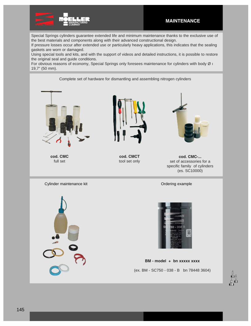
MAINTENANCE
145
Special Springs cylinders guarantee extended life and minimum maintenance thanks to the exclusive use ofthe best materials and components along with their advanced constructional design.If pressure losses occur after extended use or particularly heavy applications, this indicates that the sealinggaskets are worn or damaged.Using special tools and kits, and with the support of videos and detailed instructions, it is possible to restorethe original seal and guide conditions.For obvious reasons of economy, Special Springs only foresees maintenance for cylinders with body Ø ı19,7” (50 mm).
Complete set of hardware for dismantling and assembling nitrogen cylinders
cod. CMCfull set
cod. CMCTtool set only
cod. CMC-...set of accessories for a
specific family of cylinders(es. SC10000)
Cylinder maintenance kit Ordering example
BM - model + bn xxxxx xxxx
(ex. BM - SC750 - 038 - B bn 78448 3604)

MOUNTING SPECIFICATIONSRECOMMENDATIONS
����������
��
�������
HR ........ - N HR ........ - NA
L
L +
10
mm
Obsolete
�
150
bar
N280176
100% Cu< Cu
100%
Cu
Do not release rod uncontrolled when returning
CAUTIONAssure the rod is 100% extracted when charging. When charging cylindersmissing threaded hole at the rod end, initially fill with limited pressure of 75 psi (5 bar) to extract the rod completely; then charge to required pressure.
CAUTIONAlways wear safety glasses when
exhausting a gas spring
CAUTIONBefore servicing gas spring assure all pressure isexhausted and the rod fully retracted into the body
CAUTIONDo not exceed maximum recommended
pressure of 2175 psi (150 bar) when charging, unless otherwise stated
146
The realization of special connections and hoses, exclusiveuse of Moeller/Special Springs, allow HR self containedcylinders (with M6 charging hole) to be used in linkedsystems (non self contained cylinders).This bring a saving of 10 mm in overall length compared tothe non self contained standard version (HR...-N).
To order the new linked version, please add “NA” next tothe standard code.
Example: (4) HR 1500-50 NA
Hose and accessories: page 140-141