nj stormwater bmp · pdf filetitle: nj stormwater bmp manual author: adriana caldarelli;lisa...
TRANSCRIPT
New Jersey Stormwater Best Management Practices Manual Updated February 2016 Chapter 9. 3 Dry Wells Page 1
9.3 DRY WELLS
Dry wells are subsurface stormwater facilities that are used to
collect and temporarily store runoff from clean rooftops; runoff
is discharged through infiltration into the subsoil. Dry wells may
be used to comply with the groundwater recharge design and
performance standard of the Stormwater Management rules.
Additionally, they may also be used to reduce the volume of
clean, roof runoff.
N.J.A.C. 7:8 Stormwater Management Rules - Design and Performance Standards
Nonstructural Strategies Assist with Strategy #2; See Page 3
Water Quantity Not Allowed
Groundwater Recharge Yes
Water Quality Not Allowed
Groundwater Recharge Mechanism and Corresponding Criteria
Infiltration
Maximum Drainage Area 1 acre
Maximum Design Volume Water Quality Design Storm Volume
Maximum Drain Time 72 hours, Using Slowest Design Permeability Rate
Permeability Rate Factor of Safety 2
Minimum Design Permeability Rate of the Subsoil 0.5 inches/hour
Maximum Design Permeability Rate 10 inches/hour
Soil Testing Consistent with Appendix E Required
Minimum Distance between Dry Well Bottom and Seasonal High Water Table 2 feet

New Jersey Stormwater Best Management Practices Manual Updated February 2016 Chapter 9. 3 Dry Wells Page 2
Introduction
A dry well is a subsurface storage facility, consisting of either a structural chamber or an excavated vault that is only used to collect and temporarily store stormwater runoff from rooftops; treatment of runoff from all other surfaces is prohibited. For more information and design criteria for other types of subsurface infiltration facilities that may be used to treat runoff from other surfaces, see Chapter 9.5: Infiltration Basins. Dry wells do not have a structural outlet; instead, outflow from the system is through infiltration into the subsoil. Dry wells may be used to meet the groundwater recharge design standard at N.J.A.C. 7:8-5.4(a)2. Additionally, dry wells may be used to reduce the volume of clean, roof runoff generated by the Water Quality Design Storm.
In dry wells, the rate of infiltration is affected by the permeability of the underlying soil, the distance separating the dry well bottom from the seasonal high water table (SHWT) and the area of the dry well bottom. While loss of subsoil permeability through soil compaction is a concern, transport of dissolved pollutants by highly permeable subsoils is of equal concern. Although, in general, rooftops may not be a significant source of total suspended solids (TSS), they may be a source of nutrients and other contaminants. For example, in areas where birds tend to congregate, roofs may be a significant source of nutrients and bacteria; therefore, dry wells should not be sited in areas where there is a likelihood of high levels of rooftop pollutants. Additionally, due to the potential for groundwater contamination, the use of dry wells, and all stormwater infiltration best management practices (BMPs), is prohibited in areas where high pollutant or sediment loading is anticipated. For more information regarding stormwater runoff that may not be infiltrated, refer to N.J.A.C. 7:8-5.4(a)2.iii. However, this prohibition is limited only to areas onsite where this type of loading is expected. Therefore, because dry wells collect only clean, roof runoff, they may be used on these types of sites provided the location of the dry well is not inconsistent with an NJDEP-approved remedial action work plan or landfill closure plan.
Discharge from a dry well occurs through infiltration into the subsoil; therefore, they may not be used where their installation would create a significant risk of adverse hydraulic impacts. These impacts may include exacerbating a naturally or seasonally high water table so as to cause surficial ponding, flooding of basements, or interference with the proper operation of a subsurface sewage disposal system or other subsurface structure, or where their construction will compact the subsoil. Hydraulic impacts on the groundwater table must be assessed. For more information on groundwater mounding analysis, refer to the USGS Paper on Assessment of Impacts link on the Additional Guidance Documents page at www.njstormwater.org.
Finally, a dry well must have a maintenance plan and, if privately owned, must be protected by easement, deed restriction, ordinance, or other legal measures that prevent its neglect, adverse alteration, or removal.
Applications
The nonstructural stormwater management strategies design standard in the Stormwater Management rules must be addressed for all major development, pursuant to N.J.A.C. 7:8-5.3(a). The site evaluation for nonstructural strategies should consider all nine strategies. The design of a dry well can assist in maximizing the following strategy:
New Jersey Stormwater Best Management Practices Manual Updated February 2016 Chapter 9. 3 Dry Wells Page 3
Strategy #2: The minimization of impervious surfaces and breaking up or disconnection of the flow of runoff over impervious surfaces.
Dry wells may be used to meet the groundwater recharge requirements of the Stormwater Management rules. For more information on computing groundwater recharge, see Chapter 6: Groundwater Recharge.
Dry wells may be used reduce the volume of clean, roof runoff generated by the Water Quality Design Storm. For more information on calculating the water quality volume reduction, refer to page 7.
Design Criteria
Basic Requirements
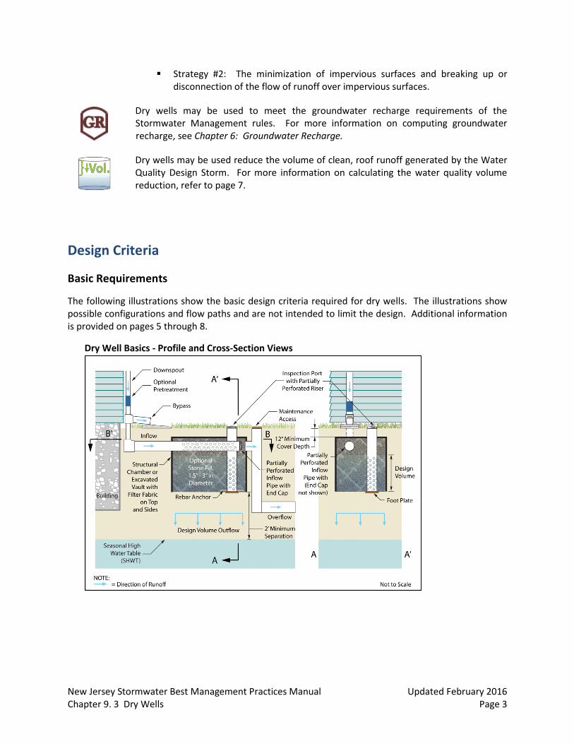
The following illustrations show the basic design criteria required for dry wells. The illustrations show possible configurations and flow paths and are not intended to limit the design. Additional information is provided on pages 5 through 8.
Dry Well Basics - Profile and Cross-Section Views

New Jersey Stormwater Best Management Practices Manual Updated February 2016 Chapter 9. 3 Dry Wells Page 4
Dry Well Basics – Plan View Section through Inflow Pipe
Inflow
The use of dry wells is limited to the collection of clean, roof runoff and is prohibited in areas where high pollutant or sediment loading is anticipated.
Maximum inflow drainage area: 1 acre.
Storage Volume
Dry wells are intended for small storm events; therefore, the maximum design volume is the volume generated by the Water Quality Design Storm.
All runoff volume in excess of the maximum design volume must be directed around the dry well by a diversion structure or device.
No standing water may remain in the dry well 72 hours after a rain event in order to allow for sufficient storage for the next rain event. Additionally, storage in excess of 72 hours may render the dry well ineffective and may result in anaerobic conditions, odor, and both water quality and mosquito breeding issues.
Infiltration may not be included in routing calculations for quantity control. Infiltration is defined as any discharge of runoff from the system into the subsoil and is sometimes referred to as exfiltration.

New Jersey Stormwater Best Management Practices Manual Updated February 2016 Chapter 9. 3 Dry Wells Page 5
Physical Components
The sides and top of the dry well must be completely lined with filter fabric in order to prohibit the migration of fines from the surrounding soil into the dry well, unless a structural chamber is provided.
The bottom of the dry well must be as level as possible in order to provide a uniform surface for infiltration.
The seasonal high water table (SHWT) and bedrock must be at least 2 feet below the bottom of the dry well.
Any stone fill within the dry well must be clean, washed aggregate between 1.5 and 3.0 inches in diameter.
Perforated pipes must be anchored; a rebar anchor and a foot plate are required for vertical pipes.
The first 12 inches of the perforated inflow pipe must be solid to facilitate the dispersion of runoff in the dry well.
The horizontal inflow pipe must be disconnected from any overflow or outflow pipe or riser.
An inspection port with removable cap is required to allow for inspection and maintenance.
Permeability Rates
The use of dry wells for stormwater management is only feasible where the subsoil is sufficiently permeable to meet the minimum permeability rate below.
Soil tests are required at the exact location of the proposed system in order to confirm its ability
to function as designed. The location of all soil testing must be consistent with Appendix E: Soil
Testing Criteria in this manual. Take note that permits may be required for soil testing in
regulated areas, such as areas regulated under the Flood Hazard Area Control Act Rules (N.J.A.C.
7:13), the Freshwater Wetlands Protection Act Rules (N.J.A.C. 7:7A), the Coastal Zone
Management Rules (N.J.A.C. 7:7), and the Highlands Water Protection and Planning Rules
(N.J.A.C. 7:38).
For dry wells associated with single-family residential development, only one soil boring is
required per dry well.
The testing of all permeability rates must be consistent with Appendix E: Soil Testing Criteria in this manual, including the required information to be included in the soil logs, which can be found in section 3.b Soil Logs. In accordance with N.J.A.C. 7:9A-6.2(j)1, Standards for Individual Subsurface Sewage Disposal Systems, the slowest tested permeability must be used for design purposes.
Since the actual permeability rate may vary from soil testing results and may decrease over time, a factor of safety of 2 must be applied to the slowest tested permeability rate to determine the design permeability rate. The design permeability rate would then be used to

New Jersey Stormwater Best Management Practices Manual Updated February 2016 Chapter 9. 3 Dry Wells Page 6
compute the system’s drain time for the maximum design volume. The drain time is defined as the time it takes to fully infiltrate the maximum design storm runoff volume through the most hydraulically restrictive layer.
The maximum design permeability rate of the subsoil is 10 inches/hour for any tested
permeability of 20 inches/hour or more.
The minimum design permeability rate of the subsoil 0.5 inches/hour, which equates to a minimum tested permeability rate of 1.0 inch/hour.
As with any infiltration BMP, groundwater mounding impacts must be assessed, as required by N.J.A.C. 7:8-5.4(a)2.iv. This includes an analysis of the reduction in permeability rate when groundwater mounding is present. Where the mounding analysis identifies adverse impacts, the dry well must be redesigned or relocated, as appropriate. The mounding analysis must provide details and supporting documentation on the methods used and assumptions made, including values used in calculations.
Safety
Dry wells must be designed to safely convey overflows to downstream drainage systems. The design of the overflow structure must be sufficient to provide safe, stable discharge of stormwater in the event of an overflow. Safe and stable discharge minimizes the possibility of adverse impacts, including erosion and flooding in down-gradient areas. Therefore, discharge in the event of an overflow must be consistent with the Standards for Off-Site Stability found in the Standards for Soil Erosion and Sediment Control in New Jersey.
Blind connections to downstream facilities are prohibited. Any connection to downstream stormwater management facilities must include access points such as inspections ports and manholes, for visual inspection and maintenance, as appropriate, to prevent blockage of flow and ensure operation as intended. All entrance points must adhere to all Federal, State, County and municipal safety standards such as those for confined space entry.
Construction Requirements
During clearing and grading of the site, measures must be taken to eliminate soil compaction at the location of a proposed dry well.
The location of the proposed dry well must be cordoned off during construction to prevent compaction of the subsoil by construction equipment or stockpiles.
The use of the location proposed for a dry well to provide sediment control during construction is discouraged; however, when unavoidable, the bottom of the sediment control basin should be at least 2 feet above the final design elevation of the bottom of the dry well.
Excavation and construction of a dry well must be performed using equipment placed outside the limits of the dry well.
The excavation to the final design elevation of the dry well bottom may only occur after all construction within its drainage area is completed and the drainage area is stabilized. If construction of the dry well cannot be delayed, berms must be placed around the perimeter of
New Jersey Stormwater Best Management Practices Manual Updated February 2016 Chapter 9. 3 Dry Wells Page 7
the dry well during all phases of construction to divert all flows away from the dry well. The berms may not be removed until all construction within the drainage area is completed and the area is stabilized.
If included, stone aggregate fill should be placed in lifts and compacted using plate compactors. A maximum loose lift thickness of 12 inches is recommended.
Post-construction testing must be performed on the as-built dry well to ensure that the as-built permeability rate is equal to or greater than the design permeability rate. Where as-built testing results in a longer drain time, corrective action must be taken. The drain time is defined as the time it takes to fully infiltrate the maximum design storm runoff volume through the most hydraulically restrictive layer.
Access Requirements
At least one inspection port that extends into the subsoil must be provided in the area of the dry well to monitor the functionality of the dry well. The inspection port exterior must be covered in such a way as to prevent the migration of material into the structure. The location of the inspection port must be shown in the maintenance plan. Additionally, the depth of stormwater in the dry well resulting from the maximum design storm must be marked on the structure and its level included in the design report and maintenance plan.
All points of access must also be covered in such a way as to prevent sediment or other material from entering the system and to prevent the accumulation of standing water, which could lead to mosquito breeding.
Access provisions must be included in the design to facilitate monitoring and maintenance.
Volume Reduction
In addition to meeting the groundwater recharge requirement at N.J.A.C. 7:8-5.4(a)2, dry wells may be used to reduce the size of downstream facilities by managing the clean, roof runoff that would otherwise have been discharged into a downstream basin. The volume reduction provided by a dry well equals the volume generated by the Water Quality Design Storm that is captured by a dry well. In some cases, it may not be possible to size a dry well for the total volume of the Water Quality Design Storm due to site constraints, such as low-permeability soils, insufficient separation from SHWT, or limited area. In cases where a dry well cannot collect the entire Water Quality Design Storm runoff volume and stormwater quantity control is required pursuant to N.J.A.C. 7:8-5.4(a)3, it may be necessary to collect overflow from the dry well and detain it in a downstream facility. Additionally, any overflow during the Water Quality Design Storm of clean roof runoff that mixes with runoff that is subject to the stormwater quality standards pursuant to N.J.A.C. 7:8-5.5 must also be treated in a downstream facility.
New Jersey Stormwater Best Management Practices Manual Updated February 2016 Chapter 9. 3 Dry Wells Page 8
Designing a Dry Well
The following examples illustrate how to use a dry well to reduce the volume generated by the Water Quality Design Storm. Example 1 features a dry well capable of collecting all of the rooftop runoff generated, whereas Example 2 depicts a dry well that captures only a portion. The examples show possible configurations and flow paths and are not intended to limit the design.
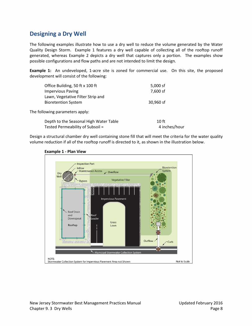
Example 1: An undeveloped, 1-acre site is zoned for commercial use. On this site, the proposed development will consist of the following:
Office Building, 50 ft x 100 ft 5,000 sf Impervious Paving 7,600 sf Lawn, Vegetative Filter Strip and Bioretention System 30,960 sf
The following parameters apply:
Depth to the Seasonal High Water Table 10 ft Tested Permeability of Subsoil = 4 inches/hour
Design a structural chamber dry well containing stone fill that will meet the criteria for the water quality volume reduction if all of the rooftop runoff is directed to it, as shown in the illustration below.
Example 1 - Plan View
New Jersey Stormwater Best Management Practices Manual Updated February 2016 Chapter 9. 3 Dry Wells Page 9
Step #1: Runoff Calculations
Using the runoff calculation method described in Technical Release 55 – Urban Hydrology for Small Watersheds (TR-55) and discussed in the NRCS Methodology section of Chapter 5: Computing Stormwater Runoff Rates and Volumes, the Water Quality Design Storm runoff volume from the 5,000 sf roof was calculated to be 431 cf. If site conditions allow, the anticipated volume reduction of this dry well is 431 cf.
Step #2: Determine the Required Volume of the Dry Well
The next step is to determine the required total volume of the dry well. The void space of the crushed stone fill is approximately 40%. The total volume, 𝑉, is calculated as follows:
𝑇𝑜𝑡𝑎𝑙 𝑉𝑜𝑙𝑢𝑚𝑒 =431 𝑐𝑓
0.40= 1,078 𝑐𝑓
Step #3: Sizing the Dry Well
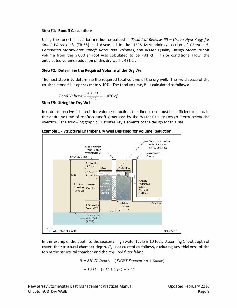
In order to receive full credit for volume reduction, the dimensions must be sufficient to contain the entire volume of rooftop runoff generated by the Water Quality Design Storm below the overflow. The following graphic illustrates key elements of the design for this site.
Example 1 - Structural Chamber Dry Well Designed for Volume Reduction
In this example, the depth to the seasonal high water table is 10 feet. Assuming 1-foot depth of cover, the structural chamber depth, 𝐻, is calculated as follows, excluding any thickness of the top of the structural chamber and the required filter fabric:
𝐻 = 𝑆𝐻𝑊𝑇 𝐷𝑒𝑝𝑡ℎ − ( 𝑆𝐻𝑊𝑇 𝑆𝑒𝑝𝑎𝑟𝑎𝑡𝑖𝑜𝑛 + 𝐶𝑜𝑣𝑒𝑟)
= 10 𝑓𝑡 − (2 𝑓𝑡 + 1 𝑓𝑡) = 7 𝑓𝑡

New Jersey Stormwater Best Management Practices Manual Updated February 2016 Chapter 9. 3 Dry Wells Page 10
As shown above, the invert of the overflow pipe is 8 inches below the top of the dry well; therefore, the depth, ℎ, to which the runoff can rise with the stone fill in place is
ℎ = 7 𝑓𝑡 − 0.67 𝑓𝑡 = 6.33 𝑓𝑡
For this example, a circular chamber has been selected for the drywell. With ℎ known, the diameter of the structural chamber, 𝐷, is calculated using the total volume, 𝑉, calculated in Step #2.
𝑉 = 𝜋𝐷2
4ℎ, which is rewritten as
𝐷 = √4𝑉𝜋ℎ
= √4 𝑥 1,078 𝑐𝑓
𝜋 𝑥 6.33 𝑓𝑡 = 14.7 𝑓𝑡
A structural chamber 7 feet in depth and 15 feet in diameter will provide sufficient volume to contain the Water Quality Design Storm volume below the invert of the overflow.
Step #4: Estimated Drain Time Calculations
Calculate the drain time of the dry well to ensure that the subsoil permeability does not limit the design. The design permeability rate must be half of the tested permeability rate; therefore, the design permeability rate is 2 inches/hour. An initial estimate is calculated as follows:
𝑂𝑢𝑡𝑓𝑙𝑜𝑤 𝑅𝑎𝑡𝑒 = 𝑆𝑢𝑏𝑠𝑜𝑖𝑙 𝐷𝑒𝑠𝑖𝑔𝑛 𝑃𝑒𝑟𝑚𝑒𝑎𝑏𝑖𝑙𝑖𝑡𝑦 𝑅𝑎𝑡𝑒 𝑥 𝐶𝑟𝑜𝑠𝑠 𝑆𝑒𝑐𝑡𝑖𝑜𝑛𝑎𝑙 𝐴𝑟𝑒𝑎
= 2 𝑖𝑛𝑐ℎ𝑒𝑠
ℎ𝑜𝑢𝑟𝑥
1 𝑓𝑜𝑜𝑡
12 𝑖𝑛𝑐ℎ𝑒𝑠 𝑥
𝜋(15)2
4 = 29.45 𝑐𝑓/ℎ𝑟
𝐷𝑟𝑎𝑖𝑛 𝑇𝑖𝑚𝑒 =𝑅𝑢𝑛𝑜𝑓𝑓 𝑉𝑜𝑙𝑢𝑚𝑒
𝑂𝑢𝑡𝑓𝑙𝑜𝑤 𝑅𝑎𝑡𝑒 =
431 𝑐𝑓29.45 𝑐𝑓/ℎ𝑟
= 14.63 ℎ𝑜𝑢𝑟𝑠
Since this is less than the allowable maximum drain time of 72 hours, the dry well meets the drain time requirement. As-built testing must be conducted to confirm the design permeability rate of the subsoil and memorialize the design drain time of the dry well in the maintenance plan. Step #5: Groundwater Mounding Analysis
Calculate the height of the groundwater mound caused by infiltration to ensure that it will neither prevent infiltration nor damage nearby structures. For information on conducting a groundwater mounding analysis, please see Chapter 6: Groundwater Recharge. For this example, it is assumed that the design meets the necessary groundwater mound requirements.
Because the dry well was designed to contain the entire volume of rooftop runoff generated by the Water Quality Design Storm, the volume reduction is 431 cf. Therefore, the area to be treated for water quality by the other stormwater BMPs on the site is reduced from 43,560 to 38,560 sf, which is an 11.5% reduction in area to be treated.
RESU
LTS
New Jersey Stormwater Best Management Practices Manual Updated February 2016 Chapter 9. 3 Dry Wells Page 11
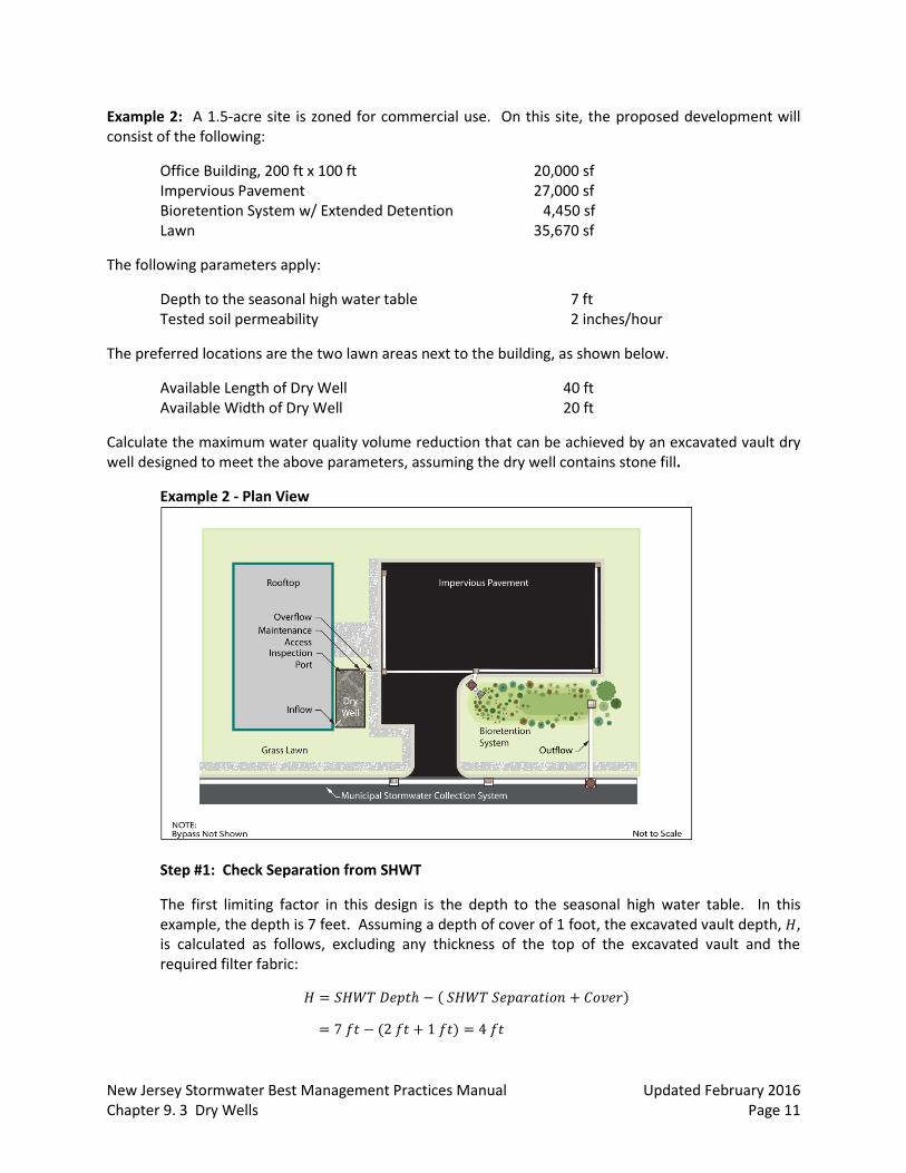
Example 2: A 1.5-acre site is zoned for commercial use. On this site, the proposed development will consist of the following:
Office Building, 200 ft x 100 ft 20,000 sf Impervious Pavement 27,000 sf Bioretention System w/ Extended Detention 4,450 sf Lawn 35,670 sf
The following parameters apply:
Depth to the seasonal high water table 7 ft Tested soil permeability 2 inches/hour
The preferred locations are the two lawn areas next to the building, as shown below.
Available Length of Dry Well 40 ft Available Width of Dry Well 20 ft
Calculate the maximum water quality volume reduction that can be achieved by an excavated vault dry well designed to meet the above parameters, assuming the dry well contains stone fill.
Example 2 - Plan View
Step #1: Check Separation from SHWT
The first limiting factor in this design is the depth to the seasonal high water table. In this example, the depth is 7 feet. Assuming a depth of cover of 1 foot, the excavated vault depth, 𝐻, is calculated as follows, excluding any thickness of the top of the excavated vault and the required filter fabric:
𝐻 = 𝑆𝐻𝑊𝑇 𝐷𝑒𝑝𝑡ℎ − ( 𝑆𝐻𝑊𝑇 𝑆𝑒𝑝𝑎𝑟𝑎𝑡𝑖𝑜𝑛 + 𝐶𝑜𝑣𝑒𝑟)
= 7 𝑓𝑡 − (2 𝑓𝑡 + 1 𝑓𝑡) = 4 𝑓𝑡

New Jersey Stormwater Best Management Practices Manual Updated February 2016 Chapter 9. 3 Dry Wells Page 12
Assuming the invert of the overflow pipe is 8 inches below the top of the dry well, the depth, ℎ, to which the runoff can rise with the stone fill in place, is calculated as follows:
ℎ = 4 𝑓𝑡 − 0.67 𝑓𝑡 = 3.33 𝑓𝑡
Step #2: Calculate the Available Capacity to Store Runoff
The second limiting factor is the available area. Using the runoff depth, ℎ, the available dimensions specified, and the void space of the stone fill, which is approximately 40%, the total volume of runoff, 𝑉, is calculated below. The volume reduction equals 𝑉, in this case.
𝑉 = 3.33𝑓𝑡 𝑥 40 𝑓𝑡 𝑥 20 𝑓𝑡 𝑥 0.4 = 1,066 𝑐𝑓
Step #3: Estimated Drain Time Calculation
Calculate the drain time of the dry well to ensure that the subsoil permeability does not limit the design. The design permeability rate must be half of the tested permeability rate; therefore, the design permeability rate is 1 inch/hour.
𝑂𝑢𝑡𝑓𝑙𝑜𝑤 𝑅𝑎𝑡𝑒 = 𝑆𝑢𝑏𝑠𝑜𝑖𝑙 𝐷𝑒𝑠𝑖𝑔𝑛 𝑃𝑒𝑟𝑚𝑒𝑎𝑏𝑖𝑙𝑖𝑡𝑦 𝑅𝑎𝑡𝑒 𝑥 𝐶𝑟𝑜𝑠𝑠 𝑆𝑒𝑐𝑡𝑖𝑜𝑛𝑎𝑙 𝐴𝑟𝑒𝑎
= 1 𝑖𝑛𝑐ℎ
ℎ𝑜𝑢𝑟 𝑥
1 𝑓𝑜𝑜𝑡
12 𝑖𝑛𝑐ℎ𝑒𝑠 𝑥 20 𝑓𝑒𝑒𝑡 𝑥 40 𝑓𝑒𝑒𝑡 = 66.66 𝑐𝑓/ℎ𝑟
𝐷𝑟𝑎𝑖𝑛 𝑇𝑖𝑚𝑒 = 𝑅𝑢𝑛𝑜𝑓𝑓 𝑉𝑜𝑙𝑢𝑚𝑒
𝑂𝑢𝑡𝑓𝑙𝑜𝑤 𝑅𝑎𝑡𝑒=
1,066 𝑐𝑓
66.66 𝑐𝑓/ℎ𝑟 = 16 ℎ𝑜𝑢𝑟𝑠
Since this is less than the allowable maximum drain time of 72 hours, the dry well meets the drain time requirement. As-built testing must be conducted to confirm the design permeability rate of the subsoil and memorialize the design drain time of the dry well in the maintenance plan.
Step #4: Calculate the Rooftop Areas Captured and not Captured
For the Water Quality Design Storm, 1.25 inches of rain will fall uniformly on the 20,000 sf rooftop. Using the NRCS methodology with a curve number of 98, the calculated runoff depth is 1.03 inches. The rooftop area that can be directed to this dry well is calculated as follows:
𝑅𝑜𝑜𝑓𝑡𝑜𝑝 𝐴𝑟𝑒𝑎 = 𝑅𝑢𝑛𝑜𝑓𝑓 𝑉𝑜𝑙𝑢𝑚𝑒𝑅𝑢𝑛𝑜𝑓𝑓 𝐷𝑒𝑝𝑡ℎ
=1,066 𝑐𝑓
1.03 𝑖𝑛𝑐ℎ𝑒𝑠 𝑥
12 𝑖𝑛𝑐ℎ𝑒𝑠1 𝑓𝑜𝑜𝑡
= 12,419 𝑠𝑓
𝐸𝑥𝑐𝑒𝑠𝑠 𝑅𝑜𝑜𝑓𝑡𝑜𝑝 𝑅𝑢𝑛𝑜𝑓𝑓 𝐴𝑟𝑒𝑎 = 20,000 𝑠𝑓 − 12,419 𝑠𝑓 = 7,581 𝑠𝑓
New Jersey Stormwater Best Management Practices Manual Updated February 2016 Chapter 9. 3 Dry Wells Page 13
Step #5: Groundwater Mounding Analysis
Calculate the height of the groundwater mound caused by infiltration to ensure that it will neither prevent infiltration nor damage nearby structures. For information on conducting a groundwater mounding analysis, please see Chapter 6: Groundwater Recharge. For this example, it is assumed that the design meets the necessary groundwater mound requirements.
The largest rooftop area for which the dry well can be sized is 12,419 sf, which leaves 7,581 sf to be directed into other BMPs for treatment. The proposed bioretention system with extended detention must be designed to treat this area, as well as the runoff from the other disturbed areas.
Considerations
When planning a dry well, consideration should be given to soil characteristics, depth to the groundwater table, sensitivity of the region, and inflow water quality. It is also important to note that the use of dry wells is recommended in this manual only for the Water Quality Design Storm or smaller storm events. Use of dry wells to infiltrate larger volumes, should only be considered when another applicable rule or regulation requires the infiltration of a larger storm event. In such a case, the dry well should be designed to infiltrate the minimum storm event required to address that rule or regulation.
In addition to the prohibition of recharge in the areas with high pollutant loading or with runoff exposed to source material as defined in N.J.A.C. 7:8-5.4(a)2iii, the utilization of dry wells should consider the impact of infiltration on subsurface sewage disposal systems, water supply wells, groundwater recharge areas protected under the Ground Water Quality Standards rules at N.J.A.C 7:9C, streams under antidegradation protection by the Surface Water Quality Standards rules at N.J.A.C. 7:9B, or similar facilities or areas geologically and ecologically sensitive to pollutants or hydrological changes. Furthermore, the location and minimum distance of the dry well from other facilities or systems shall also comply with all applicable laws and rules adopted by Federal, State, and local government entities.
Pretreatment
As with all other best management practices, pretreatment can extend the functional life of a dry well. Gutter guards, sumps, or traps with maintenance access must be included, wherever practical, to minimize the amount of coarse particles and vegetation that may enter the dry well.
Soil Characteristics
Soils are perhaps the most important consideration for site suitability. In general, County Soil Surveys can be used to obtain necessary soil data for the planning and preliminary design of dry wells; however, for final design and construction, soil tests are required at the location of a proposed dry well in accordance with Appendix E: Soil Testing Criteria in this manual. The results of this soil testing must be compared with the County Soil Survey data used in the computation of runoff rates and volumes and the design of BMPs on-site to ensure reasonable data consistency. If significant differences exist between the soil test results and the County Soil Survey data, additional soil tests are recommended to
RESU
LTS
New Jersey Stormwater Best Management Practices Manual Updated February 2016 Chapter 9. 3 Dry Wells Page 14
determine and evaluate the extent of the data inconsistency and whether there is a need for revised site runoff and BMP design computations. All significant inconsistencies should be discussed with the local Soil Conservation District prior to proceeding with such redesign to help ensure that the final site soil data is accurate.
Geology
The presence or absence of Karst topography is an important consideration when designing a dry well; in areas of the State with this type of geology, the bedrock is composed of highly soluble rock. If Karst topography is present, infiltration of runoff may lead to subsidence and sinkholes; therefore, careful consideration must be taken in these areas. For more information on design and remediation in areas of Karst topography, refer to the Standards for Soil Erosion and Sediment Control in New Jersey: Investigation, Design and Remedial Measures for Areas Underlain by Cavernous Limestone.
Maintenance
Regular and effective maintenance is crucial to ensure effective dry well performance; in addition, maintenance plans are required for all stormwater management facilities associated with a major development. There are a number of required elements in all maintenance plans, pursuant to N.J.A.C. 7:8-5.8; these are discussed in more detail in Chapter 8: Maintenance of Stormwater Management Measures. Furthermore, maintenance activities are required through various regulations, including the New Jersey Pollutant Discharge Elimination System (NJPDES) rules, N.J.A.C. 7:14A. Specific maintenance requirements for dry wells are presented below; these requirements must be included in the maintenance plan.
General Maintenance
All structural components must be inspected, at least once annually, for cracking, subsidence, spalling, erosion and deterioration.
Components expected to receive and/or trap debris must be inspected for clogging at least four times annually, as well as after every storm exceeding 1 inch of rainfall.
Disposal of debris, trash and other waste material must be done at suitable disposal/recycling sites and in compliance with all applicable local, state and federal waste regulations.
Access points for maintenance are required on all dry wells; these access points must be clearly identified in the maintenance plan. In addition, any special training required for maintenance personnel to perform specific tasks, such as confined space entry, must be included in the plan.
Drain Time
The water level in the inspection port is the primary means of measuring the infiltration rate and drain time; therefore, the water level associated with the design storm must be included in the maintenance plan.

New Jersey Stormwater Best Management Practices Manual Updated February 2016 Chapter 9. 3 Dry Wells Page 15
The design drain time for the maximum design storm runoff volume must be indicated in the maintenance plan.
If the actual drain time is longer than the design drain time, the dry well must be evaluated and appropriate measures must be taken to return the dry well to the as-built condition.
If the dry well fails to fully drain the Water Quality Design Storm within 72 hours, corrective action must be taken and the maintenance manual revised accordingly to prevent similar failures in the future.

New Jersey Stormwater Best Management Practices Manual Updated February 2016 Chapter 9. 3 Dry Wells Page 16
References
Claytor, R. and T. Schueler. December 1996. Design of Stormwater Filtering Systems. The Center for Watershed Protection. Ellicott City, MD.
Horner, R.R., J.J. Skupien, E.H. Livingston and H.E. Shaver. August 1994. Fundamentals of Urban Runoff Management: Technical and Institutional Issues. In cooperation with U.S. Environmental Protection Agency. Terrene Institute, Washington, DC.
Livingston, E.H., H.E. Shaver, J.J. Skupien and R.R. Horner. August 1997. Operation, Maintenance, & Management of Stormwater Management Systems. In cooperation with U.S. Environmental Protection Agency. Watershed Management Institute. Crawfordville, FL.
Maryland Department of the Environment. 2000. Maryland Stormwater Design Manual – Volume 1 – Stormwater Management Criteria. Water Management Administration. Baltimore, MD.
New Jersey Department of Agriculture. January 2014. Standards for Soil Erosion and Sediment Control in New Jersey. State Soil Conservation Committee. Trenton, NJ.
New Jersey Pinelands Commission. September 2014. Pinelands Comprehensive Management Plan. New Lisbon, NJ.
New Jersey Department of Environmental Protection and Department of Agriculture. December 1994. Stormwater and Nonpoint Source Pollution Control Best Management Practices. Trenton, NJ.
Ocean County Planning and Engineering Departments and Killam Associates. June 1989. Stormwater Management Facilities Maintenance Manual. New Jersey Department of Environmental Protection. Trenton, NJ.
Schueler, T.R., P.A. Kumble and M. Heraty. March 1992. A Current Assessment of Urban Best Management Practices. Metropolitan Washington Council of Governments. Washington, DC.