nl-42 / nl-52 · iii organization of this manual this manual describes the features, operation and...
TRANSCRIPT

3-20-41 Higashimotomachi, Kokubunji, Tokyo 185-8533, Japanhttp://www.rion.co.jp/english/
INSTRUCTION MANUAL
Sound Level Meter
NL-42 / NL-52

i
Organization of the NL-42/NL-52 documentation
Documentation for the Sound Level Meter NL-42/NL-52 comes in three
parts, as listed below.
Instruction Manual (this document)Describes operating procedures for the Sound Level Meter NL-42/NL-52,
connection and use of peripheral equipment such as a level recorder and
printer, and use of the memory card.
Serial Interface ManualDescribes communication with a computer, using the serial interface built
into the Sound Level Meter NL-42/NL-52. The manual covers the com-
munication protocol, use of control commands for the sound level meter,
format of data output by the sound level meter, and other topics.
Technical NotesThis document provides in-depth information about sound level meter
performance, microphone construction and characteristics, infl uence of
extension cables and windscreen on the measurement, and other topics.
* Company names and product names mentioned in this manual are usually
trademarks or registered trademarks of their respective owners.

ii
iii
Organization of this manual
This manual describes the features, operation and other aspects of the Sound Level
Meter NL-42/NL-52. If the unit is used together with other equipment to confi gure
a measurement system, consult the documentation of all other components as well.
Pages v and following contain important information about safety. Be sure to read
and observe these in full.
This manual contains the following sections.
OutlineGives basic information about the unit.
Controls and FunctionsBriefl y identifi es and explains the operation keys and connectors and all
other parts of the unit.
PreparationsExplains how to check the unit before use and how to install and set up the
unit for measurement.
CalibrationExplains how to calibrate the unit for measurement.
Reading the DisplayExplains symbols and other information shown on the display of the unit.
MeasurementExplains the basic procedures for measurement.
Store OperationExplains how to store measurement data.
iv
Input/Output ConnectorsExplains the input and output connectors of the unit.
Default SettingsLists the factory default settings of the unit.
Setup FilesExplains how to start up the unit using settings saved in a setup fi le.
Optional AccessoriesExplains how to use the optional microphone extension cable, printer, and
level recorder with the unit.
Specifi cationsLists the technical specifi cations of the unit.

v
FOR SAFETY
In this manual, important safety instructions are specially marked as shown
below. To prevent the risk of death or injury to persons and severe damage
to the unit or peripheral equipment, make sure that all instructions are fully
understood and observed.
Caution
Important
Disrega rding inst ruct ions
printed here incurs the risk of
injury to persons and/or dam-
age to peripheral equipment.
Disrega rding inst ruct ions
printed here incurs the risk of
damage to the unit.
Mentioned about the tips to
use this unit properly. (This
messages do not have to do
with safety.)
Note
WARNING Disrega rd ing inst r uct ions
printed here incurs the risk of
death or severe injury to per-
sons.

vi

vii
Quantifi er Notation(Sound level and sound pressure level are expressed uniformly as sound pres-
sure level, distinguished by the use of frequency weighting.)
Measurement valueThe time weighting characteristics
F, S, 10 ms I
LpSound pressure level
A-weighted sound pressure level LAF, LAS, LA10ms LAI
C-weighted sound pressure level LCF, LCS, LC10ms (LCI)
Z-weighted sound pressure level LZF, LZS, LZ10ms (LZI)
LeqEquivalent continuous sound level
Equivalent continuous A-weighted sound level LAeq LAIeq
Equivalent continuous C-weighted sound level LCeq (LCIeq)
Equivalent continuous Z-weighted sound level LZeq (LZIeq)
LESound exposure level
A-weighted sound exposure level LAE (LAIE)
C-weighted sound exposure level LCE (LCIE)
Z-weighted sound exposure level LZE (LZIE)
Lmax, LminMaximum sound level
Maximum A-weighted sound level LAFmax, LASmax, LA10msmax LAImax
Maximum C-weighted sound level LCFmax, LCSmax, LC10msmax (LCImax)
Maximum Z-weighted sound level LZFmax, LZSmax, LZ10msmax (LZImax)
LNPercentile sound level
Percentile A-weighted sound level LAFNn, LASNn, LA10msNn (LAINn)
Percentile C-weighted sound level LCFNn, LCSNn, LC10msNn (LCINn)
Percentile Z-weighted sound level LZFNn, LZSNn, LZ10msNn (LZINn)
LpeakPeak sound level
A-weighted peak sound level (LApeak) ---
C-weighted peak sound level LCpeak ---
Z-weighted peak sound level LZpeak ---
Ltm5Takt-max sound level
Takt-max A-weighted sound level LAtm5 ---
Takt-max C-weighted sound level (LCtm5) ---
Takt-max Z-weighted sound level (LZtm5) ---
• Z-weighted level is the same as an existing fl at-weighted level.
• The combination of peak sound level and takt-max with I character-
istics does not exist.
• Measurement value shown in brackets ( ) indicates items that can be
displayed as operation steps but are not used or not suitable.

viii

ix
Quantifi er Notation of Sound Level Meter NL-42/NL-52 According to In-
ternational Standards and JIS
(Excerpts from ISO 1996, 3891, IEC 61672-1, JIS Z 8202, 8731)
NL-42/52 notation Description Frequency
weightingISO
notationIEC
notationJIS
notation
LZ Sound level Z Lp — Lp
LA A-weighted sound level A LpA — LpA
LC C-weighted sound level C — — —
LZeqEquivalent continuous sound level Z — — —
LAeqEquivalent continuous A-weighted sound level A LAeq,T LAeq,T LAeq,T
LCeqEquivalent continuous C-weighted sound level C — LCeq,T —
LZE Sound exposure level Z — — —
LAEA-weighted sound exposure level A LAE LAE,T LAE
LCEC-weighted sound exposure level C — — —
LAN
LA05
Percentile A-weighted sound level A LAN,T
LA5,T —
LAN,T
LA5,T
LA10 LA10,T — LA10,T
LA50 LA50,T — LA50,T
LA90 LA90,T — LA90,T
LA95 LA95,T — LA95,T
LAmaxMaximum A-weighted sound level A — — —
LAminMinimum A-weighted sound level A — — —
LCpkC-weighted peak sound level C — LCpeak —
• Z-weighted level is the same as an existing fl at-weighted level.
x
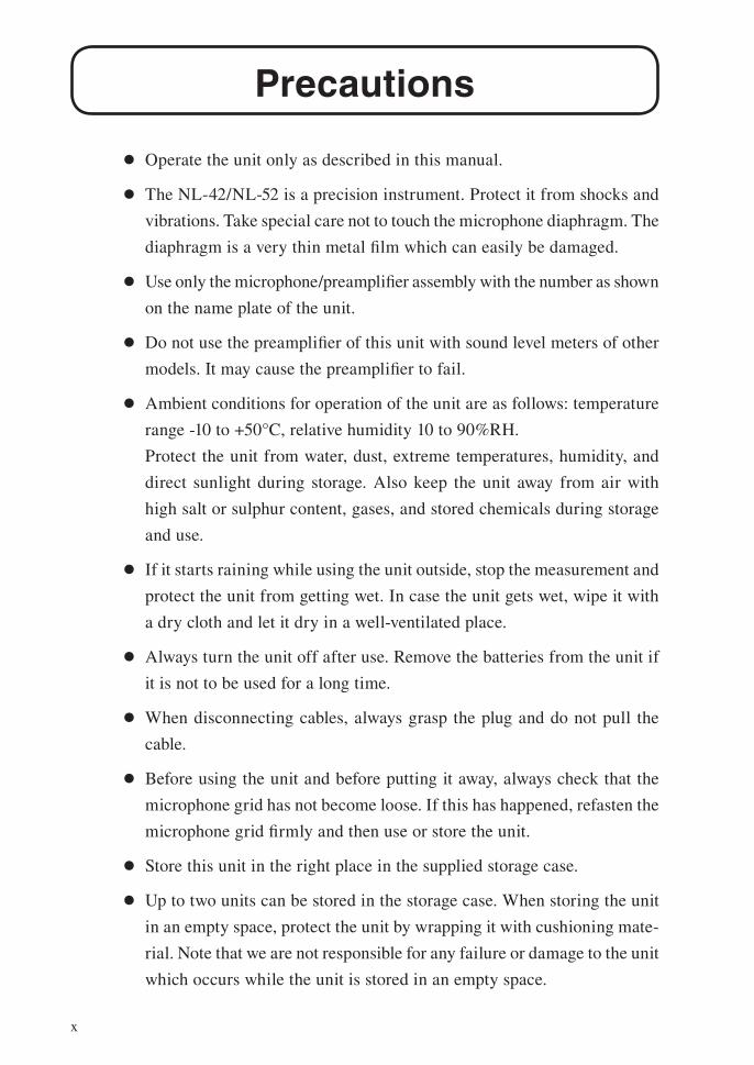
Precautions
Operate the unit only as described in this manual.
The NL-42/NL-52 is a precision instrument. Protect it from shocks and
vibrations. Take special care not to touch the microphone diaphragm. The
diaphragm is a very thin metal fi lm which can easily be damaged.
Use only the microphone/preamplifi er assembly with the number as shown
on the name plate of the unit.
Do not use the preamplifi er of this unit with sound level meters of other
models. It may cause the preamplifi er to fail.
Ambient conditions for operation of the unit are as follows: temperature
range -10 to +50°C, relative humidity 10 to 90%RH.
Protect the unit from water, dust, extreme temperatures, humidity, and
direct sunlight during storage. Also keep the unit away from air with
high salt or sulphur content, gases, and stored chemicals during storage
and use.
If it starts raining while using the unit outside, stop the measurement and
protect the unit from getting wet. In case the unit gets wet, wipe it with
a dry cloth and let it dry in a well-ventilated place.
Always turn the unit off after use. Remove the batteries from the unit if
it is not to be used for a long time.
When disconnecting cables, always grasp the plug and do not pull the
cable.
Before using the unit and before putting it away, always check that the
microphone grid has not become loose. If this has happened, refasten the
microphone grid fi rmly and then use or store the unit.
Store this unit in the right place in the supplied storage case.
Up to two units can be stored in the storage case. When storing the unit
in an empty space, protect the unit by wrapping it with cushioning mate-
rial. Note that we are not responsible for any failure or damage to the unit
which occurs while the unit is stored in an empty space.
xi
Clean the unit only by wiping it with a soft, dry cloth or, when neces-
sary, with a cloth lightly moistened with water. Do not use any solvents,
cleaning alcohol or chemical cleaning agents.
Do not try to disassemble or alter the unit. In case of an apparent malfunc-
tion, do not attempt any repairs. Note the condition of the unit clearly and
contact the supplier.
Do not tap the LCD panel or other surfaces of the unit with a pointed
object such as a pencil, screwdriver, etc.
Take care that no conductive objects such as wire, metal scraps, conduc-
tive plastics etc. can get into the unit.
To ensure continued accuracy, have the unit checked and serviced at
regular intervals. Contact the supplier.
Dispose of the unit and of batteries only according to national and local
regulations at the place of use.
We recommend that the packing inside the case be replaced regularly to
maintain “water and dust resistant performance” of this unit. Note that
the “water and dust resistant performance” will not be guaranteed when
a recommended two-year replacement cycle passes.
Please note that this product is warranted up to the product purchase price
against defects in material.
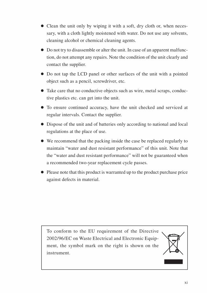
To conform to the EU requirement of the Directive
2002/96/EC on Waste Electrical and Electronic Equip-
ment, the symbol mark on the right is shown on the
instrument.

xii

xiii
Contents
FOR SAFETY .................................................................................v
Outline ............................................................................................1
Controls and Functions ...................................................................4
Front view ..................................................................................4
Bottom view ..............................................................................7
Rear view ...................................................................................8
Preparations ....................................................................................9
Power .........................................................................................9
Power on/off ............................................................................13
Windscreen (WS-10, WS-15) ...................................................15
Diffuse sound fi eld correction .................................................. 16
Memory cards (SD memory card) and program cards .............. 17
Microphone extension cables (EC-04 series) ............................ 18
Tripod mounting ......................................................................20
Connection to a printer (DPU-414) ..........................................21
Connection to a level recorder (LR-07, LR-20A) and
data recorder (DA-20, DA-40) ................................................23
Connection to a computer .......................................................24
Setting the date and time .........................................................25
Measurement in a dark location ...............................................26
Sub channel settings ................................................................28
Eco setting (Power-saving mode) .............................................30
Comparator output ................................................................... 31
Language selection ..................................................................34
Calibration ....................................................................................35
Internal calibration (Electrical calibration) ..............................35
Acoustic calibration (with sound calibrator) .............................37
Reading the Display ......................................................................39
Measurement screen display ....................................................39
Sub channel display screen ......................................................44
Processed data display screen ..................................................44
Time-Level screen ...................................................................45
Indicator messages ...................................................................46

xiv
Menu list screen .......................................................................47
System (Language) .............................................................49
Display ...............................................................................52
I/O ......................................................................................55
Store ...................................................................................57
Measure ..............................................................................60
Save/Print ...........................................................................62
Option ................................................................................63
Recall .................................................................................64
WR .....................................................................................67
MENU list items ................................................................68
Measurement .................................................................................69
Sound level (Lp) measurement .................................................69
Equivalent continuous sound level (Leq) measurement .............71
Sound exposure level (LAE), Maximum sound level (Lmax),
Minimum sound level (Lmin) and
Percentile sound level (LN) measurement ................................76
Additional processing value measurement ...............................77
Store Operation .............................................................................79
Manual mode operation ...........................................................82
Auto mode operation ...............................................................86
Marker .....................................................................................89
Timer Auto mode operation .....................................................91
Data size information ..............................................................95
About the store data format .....................................................95
About SD memory cards ..........................................................96
Data recovery ..........................................................................97
Formatting an SD memory card ...............................................97
Screen hard copy ....................................................................98
Input/Output Connectors ...............................................................99
AC OUT connector ..................................................................99
DC OUT connector ................................................................ 101
I/O connector ......................................................................... 103

xv
Default Settings ...........................................................................104
Setup Files ..................................................................................106
Resume function ....................................................................106
Loading a start up fi le at startup ............................................106
Restoring default settings (factory default settings) ................ 107
Using setup fi les ..................................................................... 108
Setting a start up fi le .............................................................. 111
Optional Accessories ................................................................... 112
Microphone extension cables (EC-04 series) .......................... 112
Printer DPU-414 .................................................................... 113
Level recorder LR-07/LR-20A ............................................... 116
Program options .................................................................... 118
Specifi cations .............................................................................. 119

xvi

1
Outline
The Sound Level Meter NL-42 and NL-52 are designed for sound level
measurements according to the IEC standard. They support diffuse sound
fi eld measurements and also meets standard requirements when the supplied
windscreen is mounted.
The NL-42 and NL-52 consist of the 1/2-inch electret condenser microphone
UC-52 (for NL-42) and UC-59 (for NL-52), preamplifi er NH-24 (for NL-42)
and NH-25 (for NL-52), and the main unit. The preamplifi er can be used by
separating and extending from the main body. The unit is equipped with the
operation keys and 3-inch backlit semitransparent color TFT LCD display to
offer good visibility for indoor/outdoor use and also in a dark location.
Also, the touch panel with the display supporting English language enables
user-friendly, intuitive operation which can be operated comfortably by per-
sons who are inexperienced in measurements.
The unit is equipped with AC OUT and DC OUT connector, I/O connector
and USB connector as the output connectors.
Since the main unit offers the “water and dust resistant performance”
equivalent to IP54 (except microphone unit), outdoor measurements can be
performed without undue worries and a risk of failure caused by a sudden
rain can be reduced.
The 113 dB wide linearity range enables measurement without switching
ranges. Measurement results data are stored on the internal memory or in-
serted SD memory card of the unit.
The unit is designed for power saving, so operates continuously for up to 24
hours on four size AA batteries.
Also, in consideration of environment, nickel metal hydride rechargeable
batteries can be used to help reduce the amount of battery waste.
Connecting to an external power is also possible. And the unit can be con-
nected the external power supply for the long time measurement.

2
Outline
Communication with a computer is possible via the built-in I/O connector
and USB connector. Because the USB connector conforms to storage speci-
fi cations, the unit will be recognized as a removable disk when connected
to a computer. This allows transfer of data from the SD memory card to the
computer without having to remove the SD memory card from the unit.
The RS-232C interface allows sending measurement data to a printer.
Various optional programs allow users to add the following functions: long-
time, continuous data recording to SD memory card, waveform recording,
and comparator output. Also, various measurements are supported including
octave and 1/3 octave band real-time analyses, FFT analysis, and additional
measurements such as time weighting I (impulse).
In addition to the measurements of sound level, equivalent continuous sound
level and maximum/minimum sound level, the unit can measure percentile
sound level and sound exposure level. Up to 1000 measurement results can
be stored in the main unit.

3
Outline
The Sound Level Meter NA-42/NL-52 allows the following quantity mea-
surements.
Main processingSimultaneous measurement of all items with selected time weighting (F,
S) and frequency weighting (A, C, Z) characteristics
Sound level Lp
Equivalent continuous sound level Leq
Sound exposure level LE
Maximum sound level Lmax
Minimum sound level Lmin
Percentile sound level LN (1 to 99) 1-increment steps,
max. 5 values, calculated from
Lp or Leq,1sec
Additional processingOne of the following measurements can be selected for simultaneous
processing with main processing.
Equivalent continuous C-weighted sound level
LCeq
C-weighted peak sound level LCpeak
Z-weighted peak sound level LZpeak
Impulse equivalent continuous sound level
LAIeq
Tact-max A-weighted sound level LAtm5
(When the optional Extended Function Program NX-42EX is not installed,
LAIeq and LAtm5 cannot be measured.)
The following options are available separately, to further enhance the
range of applications for the product.
Printer DPU 414
For producing hard copy of measurement data (including stored
memory data).
Level recorder LR-07, LR-20A (No CE)
For recording sound level changes over time.

4
Controls and Functions
Front view
Microphone/Preamplifi erThe microphone/preamplifi er unit can be detached from the main unit and
connected via an optional extension cable. This allows use at a separate
location.
Be sure to use only the microphone/preamplifi er assembly with the number
as shown on the name plate of the unit. Otherwise the product no longer
conforms to specifi cations.
DisplayThe display of the unit is a backlit LCD panel. It shows the measured sound
level as a numeric indication and as a bar graph. It also indicates the opera-
tion status of the unit and shows measurement parameters as well as warning
indications and other information.
Microphone/Preamplifier
Display
Operation key panel

5
Controls and Functions
Operation key panel
START/STOP keyPress to start or stop the measurement (including the various processing
functions).
Indicator LEDLights/fl ashes in red or blue to indicate the operation or status of the
unit.
PAUSE/CONT keyDuring a measurement, this key can be used to exclude unwanted portions
from processing. Press the key to pause measurement, and press the key
again to resume measurement.
The back-erase function makes it possible to exclude data from an interval
of several seconds (1, 3 or 5 second(s)) before the key was pressed from
processing.
During pause in manual processing, the indicator LED fl ashes in blue.
Note
The PAUSE key does not function while the store mode is Auto or Timer Auto (when the optional NX-42EX is installed).
DISPLAY keyThis key switches display of measurement screen.
In addition, this key is used to refer the explanation of the item on the
screen by the help system.
START/STOP key PAUSE/CONT key
DISPLAY key
LIGHT key POWER key
MENU/ENTER key
CAL key
key
Indicator LED

6
Controls and Functions
MENU/ENTER keyPress this key to make or finalize the setting of an item in a menu or any
other setting.
When the key is pressed at the measurement screen, the menu list screen
comes up.
CAL key (Calibration key)This key is used for calibration of the unit and for level calibration of
connected equipment.
keysThese four keys serve for selecting and setting items on menu screens.
LIGHT keyThis key turns on the display backlight, for easier reading in a dark loca-
tion. Press the key again to turn the backlight off.
When the automatic light out function was selected from the menu, the
backlight will turn itself off automatically after the preset time.
Also press this key when you want to check the measurement settings in
power-saving standby condition (see page 59).
POWER keyTurns power to the unit on and off. The key must be held down for at least
1 second to take effect.
Key lockPressing the and keys together activates the key lock. A lock symbol
appears in the bottom left corner of the display, and the operation keys
except for the LIGHT key are disabled.
If a key other than the LIGHT key is pressed, a key lock indication appears
(see page 39).
Pressing the and keys together once more cancels the key lock.
To turn the unit off, you must first cancel the key lock and then hold down
the POWER key.
The key lock does not function on the menu list screen and calibration
screen.

7
Controls and Functions
Bottom view
Bottom coverThis cover protects the connectors on the bottom during transport or storage.
Removing the cover gives access to the connectors shown above.
ImportantTo keep the water and dust resistant performance, close tightly the bottom cover of the unit.
DC IN connectorThe optional AC adapter NC-98 series can be connected here for powering
the unit from an AC outlet (100 V to 240 V AC ). The optional battery pack
BP-21 can also be connected here.
ImportantTo prevent the risk of damage, do not use any AC adapter and battery pack other than the specifi ed type.
SD card slotThe SD memory card can be inserted in this slot.
I/O connectorServes for RS-232C connection (including printer) or a comparator signal is
output here.
AC OUT connectorAn AC signal with frequency weighting is output here.
DC OUT connectorA DC signal corresponding to sound pressure level is output here.
USB connector (mini B)Serves for connection to a computer.
DC IN5-7 V
I/O AC OUT DC OUT USB
SD
AC OUTconnector
DC OUTconnector
USB connector(mini B)Bottom cover
DC IN connector
SD card slot
I/Oconnector

8
Controls and Functions
Rear view
SealThe seal guarantees the dustproof and waterproof performance of the unit.
ImportantNote that the unit will not be covered by warranty against dustproof and waterproof performances if the seal is removed.
Model plateShows various information including model number of the unit, microphone
number, preamplifi er number, serial number, and date of manufacture.
Tripod mounting threadThe unit can be mounted on a camera tripod using this thread.
Battery compartmentFour batteries (IEC R6, size AA) are inserted here. The [power-on mode]
switch is in the battery compartment. (see page 14)
Model plate
Tripod mounting thread
Battery compartment
Seal

9
Preparations
Power
The unit can be powered by four IEC R6, size AA batteries (alkaline), the
optional AC adapter NC-98 series, and the optional battery pack BP-21.
Rechargeable nickel metal-hydride batteries may also be used, but the unit
does not have a facility for charging the batteries.
WARNINGIf the unit is heated during use or the unit produces smoke or smell of burning, im-mediately remove the batteries from the unit or disconnect the AC adapter plug from the outlet, and then contact your supplier.
Note
When the AC adapter is connected, the unit will be powered from the adapter, also when batteries are inserted. (The AC adapter has priority.)In case of a power failure or other interruption of AC power, the unit will automatically switch to battery power and continue operation.
When the unit is operated on external power only, the fi le auto close function and auto shutdown func-tion may not be executed. We recommend that new batteries be set in the unit.

10
Preparations
Inserting the batteries
1. Remove the cover of the battery compartment as shown below.
2. Insert four IEC LR6, size AA batteries, paying attention to the polar-
ity as indicated in the compartment.
3. Replace the cover.
Battery compartment
IEC LR6 (sizeAA) battery
× 4
Push
Push the latch in the arrowdirection and then lift upto open the cover.
CautionTake care not to reverse the (+) and (-) po-larity when inserting the batteries. Incorrect setting of the batteries may cause battery explosion and leakage. To prevent the risk of battery fl uid leakage, remove the batteries from the unit when the unit is not used.If the fl uid from inside the battery sticks to your skin or clothing, wash it off immediately with clean water.
ImportantAlways replace all four batteries together. To prevent the risk of damage, do not mix old and new batteries or batteries of different type.
11
Preparations
The life of a set of batteries depends on usage conditions and manufacturers.
Some reference values are shown below.
Battery life (at 23°C) Alkaline batteries LR6 15 hours
Nickel metal-hydride batteries 15 hours
The life of a set of batteries is shown below when the NX-42EX is installed,
Eco setting is ON, Leq calculation interval is 10 min, and Lp store interval
is OFF.
Battery life (at 23°C) Alkaline batteries LR6 26 hours
Nickel metal-hydride batteries 25 hours
The battery life shortens by 5 % to 50 % when the display backlight continu-
ously ON (different according to the backlight brightness setting).
When either AC OUT or DC OUT is ON, battery life will be about 25 %
shorter (see page 55 to 56).
When auto store is used, battery life will be 20 to 40 % shorter.
Battery life may also be shorter when the program option is operating.
ImportantThe rechargeable nickel metal-hydride battery is not charged by the NL-42/NL-52.
Note
The life of rechargeable nickel metal-hydride battery depends on the battery type and charge condition.
In the factory default condition, AC OUT is set to “Inter lock” and DC OUT is set to “ON”. To extend the battery life, select [System (Language)] from the menu list screen and set [Eco Setting] (see page 30), or select [I/O] and set the both AC OUT and DC OUT to “OFF” (see page 99 to 102).

12
Preparations
AC adapterTo operate the unit with the AC adapter, connect it as shown below.
ImportantTo prevent the risk of damage, do not use any AC adapter other than the NC-98 series.
DC IN5-7 V
I/O AC OUT DC OUT USB
SD
DC INconnector
AC adapter NC-98 seriesOpenthe bottom cover
To AC outlet, 100 to 240 VAC, 50/60 Hz
Backup battery The unit uses a backup battery (rechargeable battery) to operate the clock.
While power to the unit is on, the backup battery will be charged. It will also
be charged while power to the unit is off if external power is connected.
The relationship between charging time and retention period is shown below.
A full charge of the backup battery is achieved after 24 hours.
Charging time Retention period
1 hour 2 days
12 hours 30 days
24 hours 45 days
Use the AC adapter when connecting external power for battery charge while the
unit is turned off. The service life of the backup battery is limited. You should have
the battery replaced about once every five years. Please contact your supplier.
Note
The charging time, retention period and service life of the backup battery may vary depending on the operating condition.
When the backup battery is old, the retention period will be shorter.

13
Preparations
Power on/off
To turn the unit onHold down the POWER key until the power-on screen appears (at least 1
second). When the screen is shown, release the POWER key. After the unit
has been started, the measurement screen appears.
During start up, the indicator LED fl ashes red blue red ...
POWER key
Indicator LED
To turn the unit offHold down the POWER key until the unit is turned off (several seconds).
When the power-off screen appears, release the POWER key.
ImportantRemove the batteries from the unit if it is to be stored for a long time with the POWER key set to OFF to prevent possible damage caused by battery leakage, and disconnect the AC adapter or battery pack.
Note
After turning the unit off, wait at least 10 seconds before turning it on again.
If the key lock has been activated, pressing the POWER key has no effect. Press the key and key simultaneously to cancel the key lock condition, and then press the POWER key.

14
Preparations
Power-on mode switchOpening the battery compartment as shown below gives access to a switch
labeled “A-B”. Normally the “A” position is used. Setting this switch to the
''B'' position allows the unit to be turned on simply by supplying power to the
DC IN connector. In this case, the POWER key on the operation key panel of
the unit has no effect.
A B [power-on mode]switch
ImportantWhen using the unit with the switch in the “B” position, do not insert batteries.
If the unit is turned off immediately after changing the setting while using the unit with the switch in the “B” position, the setting may not be re-sumed. After changing the setting, wait at least 10 seconds before turning the unit off.

15
Preparations
Windscreen (WS-10, WS-15)
When making outdoor measurements in windy weather or when measuring
air conditioning equipment or similar, wind noise at the microphone can cause
measurement errors. Such effects can be reduced by using the windscreen.
Mounting the windscreen on the microphone will cause a slight change in
frequency response, as shown in the Technical Notes.
When using the windscreen, a windscreen correction can be executed ac-
cording to the following procedure.
You can use the correction to ensure fl at frequency response when the wind-
screen is mounted.
1. Press the MENU/ENTER key to bring up the menu list screen.
2. Use the keys to select [Measure] and press the MENU/
ENTER key. The measurement setting screen appears.
3. Use the keys to select [Windscreen Correction] and press the
MENU/ENTER key. The windscreen selection screen appears.
4. Use the keys to select the model of windscreen and press the
MENU/ENTER key.
5. Press the START/STOP key to return to the measurement screen.
Note
When using the windscreen for outdoor WS-15, remove the windscreen fall prevention rubber.
Windscreen WS-10
Windscreen for outdoor WS-15
Windscreen fall prevention rubber

16
Preparations
Diffuse sound fi eld correction
When using the unit as an ANSI compliant device, set the diffuse fi eld cor-
rection to ON.
This correction feature is designed to ensure fl at frequency response in a
diffuse sound fi eld.
1. Press the MENU/ENTER key to bring up the menu list screen.
2. Use the keys to select [Measure] and press the MENU/
ENTER key. The measurement setting screen appears.
3. Use the keys to select [Diffuse Sound Field Correction] and press
the MENU/ENTER key. The ON/OFF setting screen appears.
4. Use the keys to select [ON] and press the MENU/ENTER
key.
5. Press the START/STOP key to return to the measurement screen.

17
Preparations
Memory cards (SD memory card) and program cards
Measurement data can be stored on a memory card for use and further pro-
cessing in a computer. Optional program cards can also be used for loading
software into the unit to expand the measurement functions of the unit.
Inserting a card
ImportantMake sure that power is OFF before inserting or removing a card.
Take care to insert the SD memory card with correct orientation.
If the SD memory card is removed while data are being read from or written to the card, the data may be destroyed.
Use SD memory cards provided by Rion. The per-formance of other cards will not be guaranteed.
Note that we assume no responsibility for any damage or loss of stored measurement data.
1. Open the bottom cover of the unit.
2. Insert the SD memory card into the card slot on the bottom of the
unit with the label of the card facing up. Push the card in until it is
locked in place.
3. To remove the card, push the card a bit further in, the card is released
and pops out of the card slot.
SD card slot
SD memory card
By sliding this switch inthe arrow direction, youcan write-protect thecard.
Label side shouldface up

18
Preparations
Microphone extension cables (EC-04 series)Be sure to turn power to the unit OFF before separating the microphone from the main unit.To reduce measurement deviations due to refraction effects and the acoustic infl uence of the operator, the microphone can be detached from the unit and connected via an extension cable. Available cables are listed in the table below. Combining multiple cables is also possible.
Type Length Type Length
EC-04 2 m EC-04C 30 m (reel) + 5 m (connection cable)
EC-04A 5 m EC-04D 50 m (reel) + 5 m (connection cable)
EC-04B 10 m EC-04E 100 m (reel) + 5 m (connection cable)
ImportantWith long extension cables, the cable capaci-tance restricts the upper measurement frequency and measurement level. For details, refer to the Technical Notes.
1. Loosen the preamplifi er fastening screw and remove the preamplifi er
from the main unit.
ImportantNever separate the microphone and preampli-fi er, because this can lead to damage.Before using the unit and before putting it away, always check that the microphone grid has not become loose. If this has happened, refasten the microphone grid fi rmly and then use or store the unit.Never remove the microphone grid, because this can lead to damage.
Microphone grid
Microphone
PreamplifierFastening screw
Sound level meter main unit

19
Preparations
2. Connect the extension cable to the preamplifi er and to the main unit
and fasten the connectors with the fastening screw.
3. When mounting the microphone on a tripod, fi rst fasten the micro-
phone holder (supplied with the extension cable) to the tripod. Then
insert the extension cable connector into the microphone holder.
Microphone
Microphone holder(EC03001)
Connector
Tripod
Microphone extension cable
Preamplifier

20
Preparations
Tripod mounting
For long-term measurements, the unit can be mounted on a camera tripod.
CautionProceed carefully, to avoid dropping the unit or tipping over the tripod.
When using the tripod, ensure that it is stable with the unit mounted on it.
Do not carry the unit with the tripod attached. You may be injured by tripping over or hitting against the unit.
ImportantDo not turn the screw diagonally when mount-ing or removing the unit from the tripod. Turning the screw with excessive force may damage the screw.
Note
It may be diffi cult to remove batteries while the tripod is used.

21
Preparations
Connection to a printer (DPU-414)
Connect the I/O connector on the bottom of the NL-42/NL-52 with an input
connector of a printer DPU-414, using the optional printer cable CC-42P as
shown below. The performance of other cables will not be guaranteed.
ImportantDo not insert the cable connector to the I/O connector reversely.
Setting of the sound level meter when using the printer DPU-414When using DPU-414, set the baud rate for the sound level meter following
the steps below.
1. Press the MENU/ENTER key to bring up the menu list screen.
2. Use the keys to select [I/O] and press the MENU/EN-
TER key. The I/O screen appears.
3. Use the keys to select [Communication Interface] and press the
MENU/ENTER key. The communication control function screen
appears.
4. Use the keys to select [RS-232C] and press the MENU/ENTER key.
5. Select the [Baud rate] on the I/O screen and press the MENU/ENTER
key. The baud rate screen appears.
6. Use the keys to select [19200bps] and press the MENU/ENTER key.
7. Press the START/STOP key to return to the measurement screen.
I/O connector
Printer cable CC-42P
Openthe bottom cover
To printer
With the notch up,align it with the projectionof the I/O connector.
Projection

22
Preparations
Setting the software DIP switches of the DPU-414 Turn on the power while holding down the ON LINE key of the DPU-414.
A printout showing the current status of the printer is produced.
An example showing suitable software DIP switch settings for use of the
printer with the NL-42/NL-52 is shown below. (The actual printout will be
in a different font.)
Continue ? : Push' On-line SW'
Write ? : Push' Paper feed SW'
Dip SW-1
1 (OFF) : Input = Serial
2 (ON) : Printing Speed = High
3 (ON) : Auto Loading = ON
4 (OFF) : Auto LF = OFF
5 (ON) : Setting Command = Enable
6 (OFF) : Printing
7 (ON) : Density
8 (ON) : 100 %
Continue ? : Push' On-line SW'
Write ? : Push' Paper feed SW'
Dip SW-2
1 (OFF) : Printing Columns = 80
2 (ON) : User Font Back-up = ON
3 (ON) : Character Select = Normal
4 (ON) : Zero = Normal
5 (ON) : International
6 (ON) : Character
7 (ON) : Set
8 (ON) : =Japan
Continue ? : Push' On-line SW'
Write ? : Push' Paper feed SW'
Dip SW-3
1 (ON) : Data Length = 8 bits
2 (ON) : Parity Setting = No
3 (OFF) : Parity Condition = Even
4 (OFF) : Busy Control = XON / XOFF
5 (OFF) : Baud
6 (ON) : Rate
7 (ON) : Select
8 (OFF) : = 19200 bps
Continue ? : Push'-line SW'
Write ? : Push' Paper feed SW'
DIP SW setting complete !!For details, please refer to the
documentation of the DPU-414.

23
Preparations
Connection to a level recorder (LR-07, LR-20A) and data recorder (DA-20, DA-40)
Connect The AC OUT connector on the bottom of the NL-42/NL-52 with an
input connector of level recorder (LR-07, LR-20A) and data recorder (DA-20,
DA-40), using the optional BNC - Pin output code CC-24 as shown below.
The performance of other cables will not be guaranteed.
BNC connector
AC OUTconnector Open
the bottom cover
BNC - Pin output code CC-24
To input connectoron level recorder (LR-07, LR-20A)and data recorder (DA-20, DA-40)

24
Preparations
Connection to a computer
Connect the USB connector on the bottom of the NL-42/NL-52 with a USB
connector of a computer, using the optional (generic) A - mini B USB cable
as shown below.
A memory card inserted in the unit will be recognized as a removable disk
by the computer when connected via USB, without having to install a USB
driver.
To control the setting of the sound level meter with USB commands using
the communication function, select I/O from the menu and set the [Com-
munication Interface] to USB.
When not using the communication function, set the [Communication Interface]
to OFF from the [I/O] menu screen. When USB communication is enabled,
a message requesting installation of a USB driver for USB communication
will appear when the unit is connected to a computer.
For detail using the communication function, refer to the serial interface
manual for the unit.
USB connector (mini B)
Openthe bottom cover
To computer
A - mini B USB cable

25
Preparations
Setting the date and time
The unit incorporates a clock which allows recording the date and time along
with measurement data.
Set the date and time as described below.
1. Press the MENU/ENTER key to bring up the menu list screen.
2. Use the keys to select [System (Language)] and press
the MENU/ENTER key. The system screen appears.
3. Use the keys to select [Clock Setting] and press the MENU/
ENTER key. The clock setting screen appears.
4. Use the keys to select [Year], [Month], [Day], [Hour], [Minute]
and [Second].
5. Use the keys to change the setting of the selected item.
6. Repeat the steps 4 and 5. Press the MENU/ENTER key to complete
the setting change. The clock starts moving with the new setting.
7. Press the START/STOP key to return to the measurement screen.
ImportantIf the unit is not to be used for an extended period, the main batteries should be taken out to prevent possible damage due to battery fl uid leakage. After reinserting the batteries, be sure to set the date and time.
Note
The clock in this unit has an error of about 1 minute per month. Before measurement, be sure to check and set the time if required.
An internal rechargeable backup battery serves to keep clock setting on the unit. The backup battery is automatically charged by the main batteries, but the retention period for clock setting depends on charging time (see page 12). Full charge of the backup battery requires approximate 24 hours.Clock settings screen

26
Preparations
Measurement in a dark location
Pressing the LIGHT key will turn on the display backlight, for easier read-
ing in a dark location. The backlight operation pattern can be controlled via
a menu, as follows.
1. Press the MENU/ENTER key to bring up the menu list screen.
2. Use the keys to select [System (Language)] and press
the MENU/ENTER key. The system screen appears.
3. Use the keys to select [Backlight/LCD Settings] and press the
MENU/ENTER key. The backlight/LCD settings screen appears.
4. Use the keys to select [Backlight Auto Off] and press the
MENU/ENTER key. The backlight auto off screen appears.
5. Use the keys to select the automatic turn-off interval (30 sec,
3 min, Continue) and press the MENU/ENTER key.
6. Use the keys to select [Backlight brightness] and press the
MENU/ENTER key. The level of brightness screen appears.
7. Use the keys to select the level of brightness (level 1 to level
4) and press the MENU/ENTER key. (level 1 is dark, and level 4 is
bright.)
8. Press the START/STOP key to return to the measurement screen.
To turn the backlight off before the automatic turn-off point, press the LIGHT
key.
The [level 4] setting for backlight brightness will reduce battery life by about
30 percent, and the [level 1] setting by about 5 percent.
In the case there is only one segment (red) on indication of battery status dur-
ing store operation on memory card (SD memory card), the display backlight
does not turn on.

27
Preparations
System screen Backlight/LCD settings screen

28
Preparations
Sub channel settings
To use the sub channel, you must make certain settings on a menu screen.
1. Press the MENU/ENTER key to bring up the menu list screen.
2. Use the keys to select [Measure] and press the MENU/
ENTER key. The measurement setting screen appears.
3. Use the keys to select [Sub Channel Settings] and press the
MENU/ENTER key. The sub channel settings screen appears.
4. Use the keys to select [Sub Channel Settings] and press the
MENU/ENTER key. The ON/OFF setting screen appears.
5. Use the keys to select [ON] and press the MENU/ENTER
key.
6. Use the keys to select [Frequency Weighting] and press the
MENU/ENTER key. The frequency weighting characteristics setting
screen appears.
7. Use the keys to select the frequency weighting characteristics
(A, C, Z) and press the MENU/ENTER key.
8. Use the keys to select [Time Weighting] and press the MENU/
ENTER key. The time weighting characteristics setting screen ap-
pears.
9. Use the keys to select the time weighting characteristics [F(Fast),
S(Slow), I] and press the MENU/ENTER key.
10. Press the START/STOP key to return to the measurement screen.
Note
If the sub channel is not set to “ON”, measurement value are not displayed.
Since the instantaneous data of sub channel is not saved, it will not be displayed on the recall screen (see pages 64 and 85).
When the optional Extended Function Program NX-
42EX is not installed, the time weighting characteristic
I (Impulse) cannot be selected.

29
Preparations
Measurement setting screen Sub channel settings screen
Additional processingWhen the [Sub Channel Settings] is set to ON, one of the following items
can be measured with main processing as simultaneous measurement
function (see page 77).
Equivalent continuous C-weighted sound level
LCeq
C-weighted peak sound level LCpeak
Z-weighted peak sound level LZpeak
Impulse equivalent continuous sound level
LAIeq
Tact-max A-weighted sound level LAtm5
(When the optional Extended Function Program NX-42EX is not installed,
LAIeq and LAtm5 cannot be measured.)
The frequency response of additional processing is associated with that
of sub channel. Therefore, either LCeq or LCpeak (LZpeak) can be selected
when the sub channel has C-weighting (Z-weighting).
Note
If the additional processing value is not set to “ON”
on the display menu, measurement data of additional
processing is not stored.

30
Preparations
Eco setting (Power-saving mode)
The Eco setting enables the power saving feature. A long-time measurement
can be performed using batteries only.
1. Press the MENU/ENTER key to bring up the menu list screen.
2. Use the keys to select [System (Language)] and press
the MENU/ENTER key. The system screen appears.
3. Use the keys to select [Eco Setting] and press the MENU/EN-
TER key. The confi rmation screen appears.
4. Press the MENU/ENTER key to execute the eco setting.
5. Press the START/STOP key to return to the measurement screen.
When the eco setting is executed, the setting of the item is changed automati-
cally as follows.
Sub channel setting OFF
Backlight auto off 30 sec
Backlight brightness 1
Setting the additional processings OFF
AC OUT OFF
DC OUT OFF
Communication interface OFF
LCD auto off at auto store 1 min
(only when optional NX-42EX is
installed)
Comparator OFF
(only when optional NX-42EX is
installed)

31
Preparations
Comparator output
This is an open collector output that can be used to control external equipment. When the optional Extended Function Program NX-42EX is not installed,
the comparator output cannot be set.
1. Press the MENU key to bring up the menu list screen.
2. Use the keys to select [I/O] and press the MENU/EN-
TER key. The I/O screen appears.
3. Use the keys to select [Comparator] and press the MENU/EN-
TER key. The comparator screen appears.
4. Use the keys to select [Comparator] and press the MENU/EN-
TER key. The ON/OFF setting screen appears.
5. Use the keys to select [ON] and press the MENU/ENTER
key.
6. Use the keys to select [Comparator level] and press the MENU/
ENTER key. The comparator level screen appears.
7. Use the keys to select the fi rst digit and use the keys to
set the value.
8. Use the keys to select the two lower digits and use the
keys to set the value. Then press the MENU/ENTER key. (Setting
range 25 to 130 dB, 1-dB steps)
9. Use the keys to select [Comparator band] and press the MENU/
ENTER key. The comparator band screen appears.
10. Use the keys to select the comparator band (MAIN AP, SUB
AP) and press the MENU/ENTER key.
11. Press the START/STOP key to return to the measurement screen.

32
Preparations
I/O screen Comparator screen
Connecting an external equipmentConnect the I/O connector on the bottom of the NL-42/NL-52 with an input con-
nector of an external equipment, using the optional comparator output cable CC-
42C as shown below. The performance of other cables will not be guaranteed.
ImportantDo not insert the cable connector to the I/O connector reversely.
BNC connector
I/O connector
Comparator output cable CC-42C
Openthe bottom cover
To externalequipment
With the notch up,align it with the projectionof the I/O connector.
Projection

33
Preparations
Time
Comparator signal output continuesfor 1 second after signal crosses level threshold
1 s
Comparator output
Comparatorlevel
About the comparator outputWhen the sub channel is OFF, the comparator will not function if sub chan-
nel is selected as comparator band.
The comparator signal output timing pattern is as shown below.
Note
When the sub channel is selected as comparator band, a comparator level bar indication will be shown above the bar graph, but because the bar graph shows the main channel, the comparator indication and the bar graph indication will not be matched.

34
Preparations
Language selection
The language used for displaying messages and menus can be selected as
follows.
1. Press the MENU/ENTER key to bring up the menu list screen.
2. Use the keys to select [System (Language)] and press
the MENU/ENTER key. The system screen appears.
3. Use the keys to select [Language] and press the MENU/ENTER
key. The language screen appears.
4. Use the keys to select the type of language and press the
MENU/ENTER key.
5. Press the START/STOP key to return to the measurement screen.
The language selection is memorized by the unit and will be active
also the next time the unit is turned on.
Note
Descriptions in this instruction manual are based on the premise that the [Language] is set to [English].

35
CalibrationBefore starting a measurement, the unit must be calibrated. There are two
types of calibration, namely electrical calibration using an internally gener-
ated signal and acoustic calibration using an external sound calibrator.
Internal calibration (Electrical calibration)
Calibration is carried out using a signal generator (1 kHz, sinusoidal wave)
built into the unit.
1. Press the CAL key. A calibration screen such as shown below appears.
Verify the “Internal Calibration” is displayed in the upper part of
the screen.
If “Acoustic Calibration” is shown in the upper part of the screen,
press the DISPLAY key. The calibration mode will change to “In-
ternal Calibration”.
2. Confi rm that the calibration value indication shows 124 dB steadily.
If the bar graph upper limit setting is not 130 dB, a value of [Output
Level Range Upper -6 dB] will be fl ashing as the “124 dB” value on
the calibration value indication.
3. Use the keys to bring the level indication to the specifi ed value
(124.0 dB).
4. When calibration to 124.0 dB is completed, press the CAL key once
more to return to the measurement screen.

36
Calibration
Signal output for calibration of external equipmentThe normal level range setting for calibration is scale upper limit 130 dB, but
for calibration of external equipment, another level range setting can also be
chosen. In this case, “xx dB” fl ashes on the calibration value indication.
The calibration value indication will always be 6 dB below the upper limit
of the level range setting.
Using the AC or DC output, calibration of connected equipment can be car-
ried out as follows.
1. Press the CAL key.
2. Use the keys to adjust the level indication to scale upper limit
-6 dB.
A calibration signal is supplied at the AC OUT and DC OUT con-
nector on the bottom panel of the unit.
3. Press the CAL key once more to return to the measurement screen.
Note
During a measurement of a quantity other than sound level (including when a triangle symbol is fl ashing in the top left of the display, and when the unit is in pause mode), calibration cannot be performed. Perform calibration after measurement is completed (START/STOP key has been pressed).

37
Calibration
Acoustic calibration (with sound calibrator)
For acoustic calibration, a sound calibrator is mounted to the microphone of
the sound level meter, and adjustment is performed so that the reading of the
meter is equal to the sound pressure level inside the coupler.
1. Turn off the Sound Calibrator NC-74.
2. Mount the 1/2-inch adapter on the coupler of the Sound Calibrator
NC-74.
3. Insert the microphone very carefully and slowly all the way into
the coupler.
ImportantBe very careful when inserting and removing the microphone to and from the sound calibra-tor NC-74, to avoid a sudden pressure buildup which could destroy the membrane of the mi-crophone.
4. Set the power switch of the Sound Calibrator NC-74 to ON.
1/2-inch adapterfor NC-74
Sound Calibrator NC-74

38
Calibration
5. Press the CAL key. A calibration screen such as shown below ap-
pears.
Verify the “Acoustic Calibration” is displayed in the upper part of
the screen.
If “Internal Calibration” is shown in the upper part of the screen, press
the DISPLAY key. The calibration mode will change to “Acoustic
Calibration”.
6. Use the keys to adjust the reading of the NL-42/NL-52 to the
value shown below.
NL-42: 93.9 dB
NL-52: 94.0 dB
7. Press the CAL key. The measurement screen returns.
8. Turn off the Sound Calibrator NC-74 and the NL-42/NL-52.
9. Remove the microphone very carefully and slowly from the cou-
pler.
Note
For details on the Sound Calibrator NC-74, refer to the documentation of that product.

39
Reading the Display
Measurement screen displayThe illustration below shows all elements of the display for explanation pur-
poses. In actual operation, such a screen will not be shown.
Comp
Store
Diffuse sound field correction
Back-erase function
SD memory card insertion indicator
SD memory card remaining capacity
Delay time (self-timer)Operation/measurement elapsed time
Address
Total measurement timeLeq calculation interval
Comparator
Overload indication/Overload indication of output
Measurement in progresssymbol
Frequency weighting of AC output
Current date and time
Key lock
Touch panel lockUSB/RS-232C connection
Battery status
Level display
Time weighting
Frequency weighting
Under-range indication
Bar graphBar graph level range
Auto store displayLp store interval
Store mode
Windscreen correction
Mode of analysis
40
Reading the Display
Diffuse sound fi eld correctionIndicates that the unit has been set up for measurement in a diffuse sound
fi eld (see page 16).
Back-erase functionIndicates that the back-erase function has been set to 1s, 3s, or 5s (see
page 73).
SD memory card insertion indicatorShown when an SD memory card is inserted in the unit (see page 17).
SD memory card remaining capacityShows the remaining capacity of an inserted SD memory card.
Delay timeShows the delayed measurement time set by “Delay Time” (see page 72).
If the “Delay Time” is set to OFF, the delay time is not displayed.
Operation/measurement elapsed timeShows the elapsed time from the start of measurement.
AddressShows the current memory address. In manual store mode, the indication
is red if there are data in that address.
Total measurement timeWhen the store mode is Auto, the total measurement time is displayed
(see page 87).
Store modeShows the selected mode for storing data in memory (Manual, Auto, or
Timer Auto) (see page 79).
Note
When the optional Extended Function Program NX-42EX is not installed, the Auto and Timer Auto
cannot be selected.
Leq calculation intervalWhen the store mode is Auto or Timer Auto, the set Leq calculation in-
terval is displayed (see page 87, 92).

41
Reading the Display
Lp store intervalWhen the store mode is Auto or Timer Auto, the set Lp store interval is dis-
played. (see page 87, 92)
ComparatorWhen the comparator function has been set to ON, the comparator level
is shown as an orange line on the bar graph. When a signal exceeds that
level, the indication [Comp] appears, and a signal is output from the I/O
connector on the bottom panel (open collector) (see page 31).
Note
When the optional Extended Function Program NX-42EX is not installed, the comparator cannot be selected.
Overload indicationWhen a sound level overload condition is detected, the indication
(white on black) is shown for at least 1 second.
If processed data contain signal overload data, the indication is
shown. This indication remains on the processed data display screen until
the next processing measurement is started.
Overload indication of output
When a sound level overload condition over the upper limit of bargraph
is detected, the indication (white on black) is shown for at least 1
second. If this indication appears, increase the bargraph range setting.
Measurement in progress symbolWhen a measurement is in progress, the symbol fl ashes. The indicator
LED also fl ashes in red.
During auto store, the symbol also fl ashes. The indicator LED fl ashes
in red.
During measurement standby, the symbol is shown.
During measurement pause, the symbol is shown. The indicator LED
fl ashes in blue.
Frequency weighting of AC outputShows the frequency weighting of the output signal set by “AC OUT”
(see page 99).

42
Reading the Display
Current date and timeShows the current date and time.
Touch panel lockIndicates that the touch panel lock function has been set to ON. Touch panel
operations are disabled while this symbol is displayed (see page 51).
Key lockPressing the key and key simultaneously activates the key lock con-
dition and causes this symbol to appear. To cancel the condition, press
the key and key once more together (see page 6).
USB/RS-232C connectionIndicates that the communication control function has been set to USB
or RS-232C (see page 56).
Battery statusWhen the unit is operated on battery power, you should regularly check
this indication. The number of white segments will decrease as the bat-
teries get used up. When the indication starts to flash in red, replace the
batteries with a fresh set.
When the unit is being powered from an AC adapter or a battery pack,
the symbol is shown.
Level displayShows the measured sound level in the main channel. (The display is
updated every second.)
Frequency weightingIndicates the main channel frequency weighting characteristic.
A: A-weighting, C: C-weighting, Z: Z-weighting (Flat response)
Batteries good Batteries getting low Indication flashesReplace batteries
White White White Red Red

43
Reading the Display
Time weightingIndicates the main channel time weighting characteristic.
F: Fast, S: Slow
Under-range indicationWhen a signal under-range condition is detected, the indication
(white on black) is shown.
If processed data contain signal under-range data, the indication
is shown. This indication remains on the processed data display screen
until the next processing measurement is started.
Note
When the [sub channel settings] is set to On, the under-range indication is based on the frequency weighted measurement value in the channel in which the measurement lower limit is lower.
When A-weighting and C-weighting, or A-weighting and Z-weighting are selected (in either channel), the under-range indication is based on the A-weighted measurement value. When C-weighting and Z-weight-ing are selected, the under-range indication is based on the C-weighted measurement value.
Bar graphShows the sound level as a bar graph indication. (The display is updated
every 100 msec.)
Bar graph level rangeShows the upper and lower limit of the bar graph. The range can be changed
using the [Display] setting in the menu list screen (see page 53 to 54).
Auto store displayLights when the measurement data is being stored in the memory using
Auto or Timer Auto mode.
Windscreen correctionShows the model of windscreen set by windscreen correction function
(see page 15).
Mode of analysisIndicates the condition of the display screen.

44
Reading the Display
Sub channel display screen
The sub channel level can be displayed on the measurement screen by set-
ting [Sub Channel Settings] to ON on the [Measure] screen from the menu
(see page 28).
Processed data display screenThe measurement items, which are set to ON on the [Display] screen from
the menu, will be displayed on the measurement screen by pressing the DIS-
PLAY key (see page 52).
Main channel level display
Sub channel level display

45
Reading the Display
Time-Level screen
While [Time-Level] is set to ON on the [Display] screen from the menu,
the time-level screen will be displayed by pressing the DISPLAY key on the
measurement screen (see page 53).

46
Reading the Display
Indicator messages
When keys such as START/STOP or PAUSE/CONT are pressed, indicator mes-
sages such as shown below will appear on the display for about 1 second.
When START/STOP key was pressedand processing has started
When PAUSE/CONT key was pressedand operation is paused
When PAUSE/CONT key was pressedand processing has resumed
When START/STOP key was pressedand processing has ended
When PAUSE/CONT key was pressed during processing(with back-erase function set to ON)

47
Reading the Display
Menu list screen
When the measurement screen is displayed, pressing the MENU/ENTER
key brings up the menu list screen as shown below.
Use the keys to select the desired menu and press the MENU/
ENTER key.
Pressing the DISPLAY key displays explanation screen of the item that has
been selected.
Pressing the PAUSE/CONT key switches back to the screen before the menu
list screen is displayed.
Pressing the START/STOP key switches back to the measurement screen.

48
Reading the Display
The following settings of Frequency, Time Weighting and Sub Ch can be
done with the touch panel. (The current setting is shown when the menu list
screen is displayed.) Touch the screen directly with your fi nger.
FrequencySelects the frequency weighting characteristic for the main channel.
Each press of the “Frequency” on the screen with the fi nger cycles through
the following settings.
“A”, “C”, “Z”
Time WeightingSelects the time weighting characteristic for the main channel.
Each press of the “Time Weighting” on the screen with the fi nger cycles
through the following settings.
“F (Fast)”, “S (Slow)”
Sub ChSelects whether or not to display the sound level of the sub channel measure-
ment.
Each press of the “Sub Ch” on the screen with the fi nger cycles through the
ON and OFF.

49
Reading the Display
System (Language)This screen sets the item concerning the system of the unit.
Use the keys to select [System (Language)] and press the
MENU/ENTER key. The system screen appears.
Each item of the system screen is selected using the key.
Pressing the DISPLAY key displays explanation screen of the item that has
been selected.
Pressing the PAUSE/CONT key switches back to the menu list screen.
Pressing the START/STOP key switches back to the measurement screen.
Read/Save setting Displays the screen to save a setting for the unit and read the saved set-
ting.
Select [Read/Save setting] and press the MENU/ENTER key. The setting
operation screen appears (see page 107).
Clock SettingsDisplays the screen to set date and time of the internal clock of the
unit.
Select [Clock Settings] and press the MENU/ENTER key. The clock set-
tings screen appears (see page 25).
Symbol shows thata next menu level exists.
/ / / keysUseto select the item and pressthe MENU/ENT key.The next menu level appears.

50
Reading the Display
Backlight/LCD Settings Displays the screen to set the function of the backlight and the LCD of
the unit.
Select [Backlight/LCD Settings] and press the MENU/ENTER key. The
backlight/LCD settings screen appears (see page 26).
Battery TypeDisplays the screen to select the type of battery used for the unit. The
battery power corresponding to the selected battery is displayed on the
measurement screen.
Select [Battery type] and press the MENU/ENTER key. The battery type
screen appears.
Use the keys to select the battery type (Alkaline, Ni-MH[Nickel-
metal hydride]) and press the MENU/ENTER key.
Card Format (can only be selected when SD memory card is inserted)
Formats the inserted SD memory card.
Select [Card Format] and press the MENU/ENTER key. The confi rma-
tion screen appears.
Press the MENU/ENTER key to format the card.
Press the PAUSE/CONT key when not formatting the card.
Free space / SD card capacityDisplays the free space and the memory capacity of the inserted SD
memory card. The both free space and memory capacity are read by the
automatic operation, and cannot be changed.
Note
If the following operation is performed while the USB cable is connected, the free space will not be displayed correctly. In this case, cycle the power to the unit, or remove the SD memory card and insert it again.
* Have this unit recognized as a removable disk, move the data to a computer and then move the data back to the unit.

51
Reading the Display
IndexDisplays the screen to set the identifi cation number of the unit when
multiple units are used in a parallel measurement.
Select [Index] and press the MENU/ENTER key. The index screen ap-
pears.
Use the keys to select the digit, and use the keys to set the
value (1 to 255). Then press the MENU/ENTER key.
Note
Measurement data cannot be selected when recalling it on a unit with a different index number (viewing impossible).
Program Information Displays the version information screen of the program of the unit.
Select [Program Information] and press the MENU/ENTER key. The
program information screen appears.
Touch Panel LockDisplays the screen to select whether to set the touch panel lock function
to prevent a wrong operation effective.
Select [Touch Panel Lock] and press the MENU/ENTER key. The ON/
OFF setting screen appears.
Use the keys to select the ON/OFF setting and press the MENU/
ENTER key.
Eco Setting (Power saving mode)Enters the power-saving mode.
Select [Eco Setting] and press the MENU/ENTER key. The confi rmation
screen appears (see page 30).
LanguageDisplays the screen to select the language used for displaying messages
and menus.
Select [Language] and press the MENU/ENTER key. The language screen
appears (see page 34).
52
Reading the Display
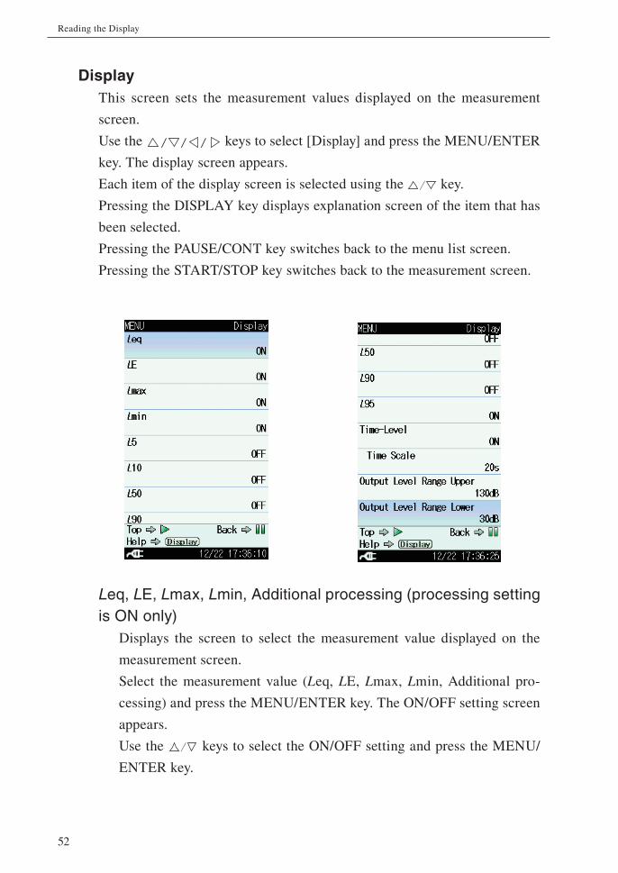
DisplayThis screen sets the measurement values displayed on the measurement
screen.
Use the keys to select [Display] and press the MENU/ENTER
key. The display screen appears.
Each item of the display screen is selected using the key.
Pressing the DISPLAY key displays explanation screen of the item that has
been selected.
Pressing the PAUSE/CONT key switches back to the menu list screen.
Pressing the START/STOP key switches back to the measurement screen.
Leq, LE, Lmax, Lmin, Additional processing (processing setting is ON only)
Displays the screen to select the measurement value displayed on the
measurement screen.
Select the measurement value (Leq, LE, Lmax, Lmin, Additional pro-
cessing) and press the MENU/ENTER key. The ON/OFF setting screen
appears.
Use the keys to select the ON/OFF setting and press the MENU/
ENTER key.

53
Reading the Display
LN1, LN2, LN3, LN4, LN5Displays the screen to select the percentile sound level displayed on the
measurement screen.
To set the L1 to L99 value for LN1 to LN5, use the keys to change
the value (only LN5 can be set the value from L0.1 to L99.9.).
Select the percentile sound level (LN1 to LN5) and press the MENU/EN-
TER key. The ON/OFF setting and value setting screen appears.
Use the keys to select the ON/OFF setting, and use the keys
to set the value (1 to 99). Then press the MENU/ENTER key.
Time-LevelDisplays the screen to select whether to display the time-level screen.
Select [Time-Level] and press the MENU/ENTER key. The ON/OFF
setting screen appears (see page 45).
Use the keys to select the ON/OFF setting and press the MENU/
ENTER key.
Time ScaleWhen [Time-Level] is set to “ON”, this item is displayed.
Displays the screen to select time-scale of time-level screen.
Select [Time Scale] and press the MENU/ENTER key. The time scale
screen appears.
Use the keys to select the time scale (20s, 1min, 2min) and press
the MENU/ENTER key.
Output Level Range UpperDisplays the screen to set the upper bound value of the bar graph and
fullscale of output voltage on the measurement screen.
Select [Output Level Range Upper] and press the MENU/ENTER key.
The upper limit of bar graph screen appears.
Use the keys to set the value (70 to 130, 10 dB step). Then press the
MENU/ENTER key.

54
Reading the Display
Output Level Range LowerDisplays the screen to set the lower bound value of the bar graph on the
measurement screen.
Select [Output Level Range Lower] and press the MENU/ENTER key.
The lower limit of bar graph screen appears.
Use the keys to set the value (20 to 80, 10 dB step). Then press the
MENU/ENTER key.
The value of lower limit cannot be set the value set by the “Output Level
Range Upper” or more.
55
Reading the Display
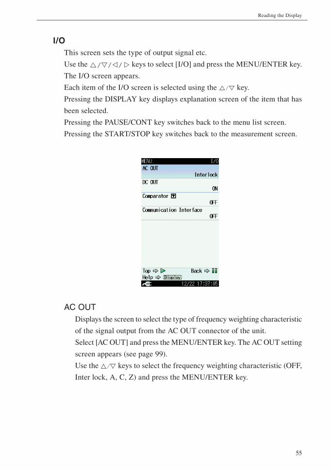
I/OThis screen sets the type of output signal etc.
Use the keys to select [I/O] and press the MENU/ENTER key.
The I/O screen appears.
Each item of the I/O screen is selected using the key.
Pressing the DISPLAY key displays explanation screen of the item that has
been selected.
Pressing the PAUSE/CONT key switches back to the menu list screen.
Pressing the START/STOP key switches back to the measurement screen.
AC OUTDisplays the screen to select the type of frequency weighting characteristic
of the signal output from the AC OUT connector of the unit.
Select [AC OUT] and press the MENU/ENTER key. The AC OUT setting
screen appears (see page 99).
Use the keys to select the frequency weighting characteristic (OFF,
Inter lock, A, C, Z) and press the MENU/ENTER key.
56
Reading the Display
DC OUTDisplays the screen to select whether to output the DC signal from the
DC OUT connector of the unit.
Select [DC OUT] and press the MENU/ENTER key. The ON/OFF setting
screen appears (see page 101).
Use the keys to select the ON/OFF setting and press the MENU/
ENTER key.
Comparator Displays the screen to set the comparator signal output (open collector
output can be used to control external equipment) from the I/O connec-
tor of the unit.
Select [Comparator] and press the MENU/ENTER key. The comparator
screen appears (see page 31).
Note
When the optional Extended Function Program NX-42EX is not installed, the comparator cannot be selected.
Communication InterfaceDisplays the screen to select a type of communication with a computer
or printer to be connected to the unit.
Select [Communication Interface] and press the MENU/ENTER key. The
communication interface screen appears.
Use the keys to select the communication type (OFF, USB, RS-232C)
and press the MENU/ENTER key.
Baud rateWhen [Communication Interface] is set to “RS-232C”, this item is dis-
played.
Displays the screen to select the baud rate value.
Select [Baud rate] and press the MENU/ENTER key. The baud rate
screen appears.
Use the keys to select the baud rate value (9600bps, 19200bps,
38400bps, 57600bps, 115200bps) and press the MENU/ENTER key.
57
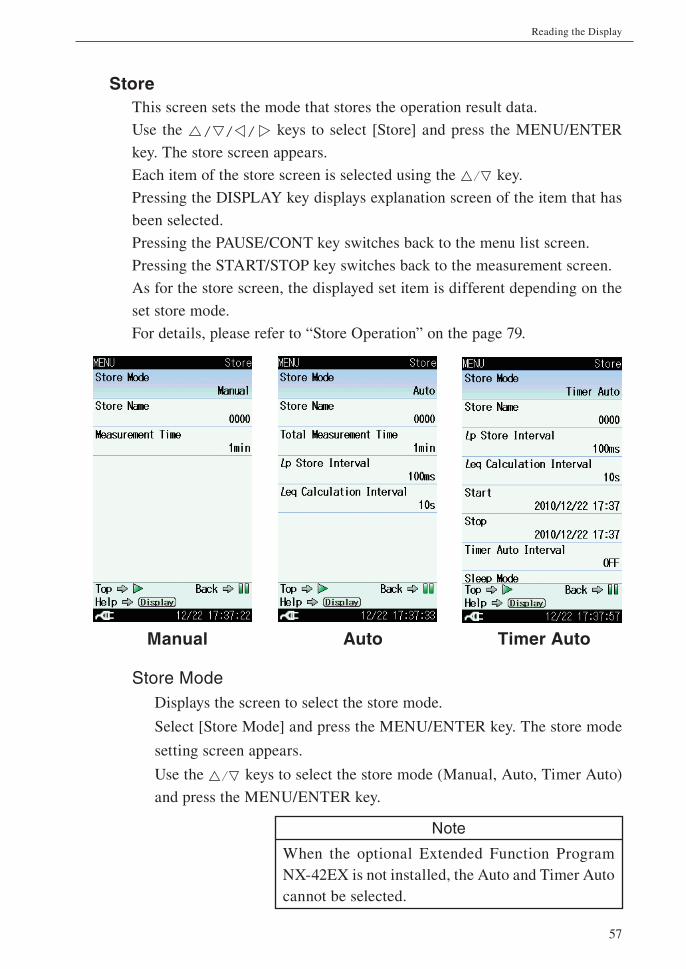
Reading the Display
StoreThis screen sets the mode that stores the operation result data.
Use the keys to select [Store] and press the MENU/ENTER
key. The store screen appears.
Each item of the store screen is selected using the key.
Pressing the DISPLAY key displays explanation screen of the item that has
been selected.
Pressing the PAUSE/CONT key switches back to the menu list screen.
Pressing the START/STOP key switches back to the measurement screen.
As for the store screen, the displayed set item is different depending on the
set store mode.
For details, please refer to “Store Operation” on the page 79.
Manual Auto Timer Auto
Store ModeDisplays the screen to select the store mode.
Select [Store Mode] and press the MENU/ENTER key. The store mode
setting screen appears.
Use the keys to select the store mode (Manual, Auto, Timer Auto)
and press the MENU/ENTER key.
Note
When the optional Extended Function Program NX-42EX is not installed, the Auto and Timer Auto cannot be selected.
58
Reading the Display
Store Name (common to each mode)Displays the screen to set the identifi cation number of the store data.
(0000 to 9999)
Select [Store Name] and press the MENU/ENTER key. The store name
screen appears.
When the SD memory card has not been inserted, the identifi cation num-
ber cannot be set.
Measurement Time (Manual mode)Displays the screen to select the measurement time in the Manual mode.
Select [Measurement Time] and press the MENU/ENTER key. The mea-
surement time screen appears.
Total Measurement Time (Auto mode)Displays the screen to select the total measurement time in the auto
mode.
Select [Total Measurement Time] and press the MENU/ENTER key. The
total measurement time screen appears.
User setting (Manual mode and Auto mode)When [Manual] is selected from [Measurement Time] of the Manual mode
or [Total Measurement Time] of the Auto mode, the user setting items
will be displayed and measurement time can be set arbitrarily.
The maximum settable time is 24 hours with the Manual mode and 1000
hours with the Auto mode.
Lp Store Interval (Auto mode and Timer Auto mode)Displays the screen to select the Lp store interval in the Auto mode or
Timer Auto mode.
Select [Lp Store Interval] and press the MENU/ENTER key. The Lp store
interval screen appears.
Leq Calculation Interval (Auto mode and Timer Auto mode)Displays the screen to select the Leq calculation interval in the Auto mode
or Timer Auto mode.
Select [Leq Calculation Interval] and press the MENU/ENTER key. The
Leq calculation interval screen appears.
59
Reading the Display
Start (Timer Auto mode)Displays the screen to set the measurement start time in the Timer Auto
mode.
Select [Start] and press the MENU/ENTER key. The start time setting
screen appears.
When the start time setting screen is displayed for the first time, current
time is indicated.
Stop (Timer Auto mode)Displays the screen to set the measurement stop time in the Timer Auto
mode.
Select [Stop] and press the MENU/ENTER key. The stop time setting
screen appears.
Timer Auto Interval (Timer Auto mode)Displays the screen to select the timer auto interval in the Timer Auto
mode.
Select [Timer Auto Interval] and press the MENU/ENTER key. The timer
auto interval screen appears.
Sleep Mode (Timer Auto mode)Displays the screen to select whether to set the sleep mode.
Select [Sleep Mode] and press the MENU/ENTER key. The ON/OFF
setting screen appears.
When sleep mode is enabled, the unit will enter a power-saving standby
condition at 60 seconds after pressing the START/STOP key and during
intervals between measurements. In this mode, power consumption is re-
duced to about 1/10. The LCD panel is off, and the indicator LED flashes
in blue once every 5 seconds. 90 seconds before the start of measurement,
the unit will wake up and go into standby until measurement begins.
To check the measurement settings in standby condition, press the LIGHT
key. The display will come on temporarily and will turn itself off again
if no further operation steps are taken. During standby, the LCD panel is
off, and the AC and DC outputs, USB connector, RS-232C, comparator
functions etc. are also disabled. If one of these functions is required, set
the sleep mode to OFF.
60
Reading the Display
MeasureThis screen sets the correction of the measurement etc.
Use the keys to select [Measure] and press the MENU/ENTER
key. The measurement setting screen appears.
Each item of the measurement setting screen is selected using the
key.
Pressing the DISPLAY key displays explanation screen of the item that has
been selected.
Pressing the PAUSE/CONT key switches back to the menu list screen.
Pressing the START/STOP key switches back to the measurement screen.
Frequency WeightingDisplays the screen to select the frequency weighting characteristics for
the main channel.
Select [Frequency Weighting] and press the MENU/ENTER key. The
frequency weighting screen appears.
Use the keys to select the frequency weighting characteristics (A, C,
Z) and press the MENU/ENTER key. The same can be performed using
the touch panel on the menu list screen.

61
Reading the Display
Time WeightingDisplays the screen to select the time weighting characteristics for the
main channel.
Select [Time Weighting] and press the MENU/ENTER key. The time
weighting screen appears.
Use the keys to select the time weighting characteristics (F[Fast],
S[Slow]) and press the MENU/ENTER key. The same can be performed
using the touch panel on the menu list screen.
Windscreen CorrectionDisplays the screen to select the type of windscreen for windscreen cor-
rection.
Select [Windscreen Correction] and press the MENU/ENTER key. The
windscreen correction screen appears (see page 15).
Diffuse Sound Field Correction (DF)Displays the screen to select whether to set the diffuse sound fi eld cor-
rection.
Select [Diffuse Sound Field Correction (DF)] and press the MENU/EN-
TER key. The ON/OFF setting screen appears (see page 16).
Delay TimeDisplays the screen to select the delayed measurement time that is an
interval starting at the point the start key is pressed.
Select [Delay Time] and press the MENU/ENTER key. The delay time
screen appears (see page 72).
Back EraseDisplays the screen to select whether to exclude the data obtained just
before a pause of measurement from the processing.
Select [Back Erase] and press the MENU/ENTER key. The back erase
screen appears (see page 73).
Sub Channel Settings Displays the screen to set the sub channel settings and the additional
processing settings.
Select [Sub Channel Settings] and press the MENU/ENTER key. The sub
channel settings screen appears (see page 28).

62
Reading the Display
Save/PrintThe measurement data or recall data displayed on the screen can be saved
or printed on the save/print screen.
Use the keys to select [Save/Print] and press the MENU/ENTER
key. The save/print screen appears.
Each item of the save/print screen is selected using the key.
Store dataStores the displayed measurement data. This is displayed when Manual
measurement (processing) data exist.
Select [Store data] and press the MENU/ENTER key.
Screenshot (BMP)Saves the displayed measurement screen to the internal memory in BMP
(bitmap) format (see page 98).
Select [Screenshot (BMP)] and press the MENU/ENTER key.
The data capacity is approximately 300 kByte per fi le.
PrintPrints the displayed measurement data to the printer connected with the
unit.
Select [Print] and press the MENU/ENTER key. (see page 113)
CancelShuts the save/print screen.
Select [Cancel] and press the MENU/ENTER key.

63
Reading the Display
OptionThis screen switches the function from the unit to each program when an
optional program is installed.
Use the keys to select [Option] and press the MENU/ENTER
key. The option screen appears.
Each item of the switch function screen is selected using the key.
Pressing the PAUSE/CONT key switches back to the menu list screen.
Pressing the START/STOP key switches back to the measurement screen.
OptionSelect a desired program name to switch the function.
Select the program name to be used and press the MENU/ENTER key.
Either NL-42 or NL-52 is displayed depending on the model used.
Program names which are not installed will not be displayed.

64
Reading the Display
RecallThis screen displays a stored data on internal memory or SD memory card.
Use the keys to select [Recall] and press the MENU/ENTER
key. The recall screen appears.
Use the keys to select a save location of data and the keys to select
a data fi le.
Pressing the PAUSE/CONT key switches back to the menu list screen.
Pressing the START/STOP key switches back to the measurement screen.
Note
It may take some time to read data and display the recall screen if the volume of stored data is large.
Save location of data
Data fi les
The save location of data can be “Internal Memory Manual”, “SD Manual”,
“SD Auto Lp” or “SD Auto Leq”. Without an SD memory card, only “Internal
Memory Manual” is available.

65
Reading the Display
Select data fi le and press the MENU/ENTER key. The fi le processing screen
appears.
Confi rm the dataDisplays the measurement data of the selected data fi le.
Select [Confi rm the data] and press the MENU/ENTER key.
Delete the dataDeletes the selected data fi le.
Select [Delete the data] and press the MENU/ENTER key. The confi rma-
tion screen appears.
Select [Yes] and press the MENU/ENTER key.

66
Reading the Display
Copy to the card (only internal memory data)Copies the selected internal memory data fi le to the inserted SD memory
card.
Select [Copy to the card] and press the MENU/ENTER key. The store
name set screen appears.
Set the store name (number of four digits) at the copy destination and
press the MENU/ENTER key.
CancelShuts the fi le processing screen.
Select [Cancel] and press the MENU/ENTER key.

67
Reading the Display
WRSelect this screen to record the waveform using optional program NX-
42WR.
If NX-42WR is not installed, it is not possible to select this screen.
For details, please refer to the instruction manual of Waveform Recording
Program NX-42WR.

68
Reading the Display
MENU list items
System (Language)Read/Save Settings [v]---------- Load Default Settings
Internal Memory---- List of setting groups on internal memory
Startup File
SD---- List of setting groups on SD memory card
Clock Settings
Backlight/LCD Settings [v]-----Backlight Auto Off
Backlight brightness
LCD Auto Off (Auto Store)
Battery Type---- Alkaline/Ni-MH
Card Format
Index
Program Information [v]--------Model, Version
Touch Panel Lock
Eco Setting
Language---- /English
DisplayLeq, LE, Lmax, Lmin, (When Additional processing is ON: LCeq, LCpeak, LZpeak, LAIeq, LAtm5),
LN1, LN2, LN3, LN4, LN5, Time-Level (When Time-Level is ON: Time Scale),
Output Level Range Upper, Output Level Range Lower
I/OAC OUT----OFF/Interlock/A/C/Z
DC OUT
Comparator [v]------------------- Comparator ON/OFF, Comparator level, Comparator band
Communication Interface----OFF/USB/RS-232C (When RS-232C is selected: Baud rate)
StoreStore Mode----Manual/Auto/Timer Auto
Manual----Store Name, Measurement Time
Auto----Store Name, Total Measurement Time, Lp Store Interval, Leq Calculation Interval
Timer Auto----Store Name, Lp Store Interval, Leq Calculation Interval, Start, Stop, Timer Auto Interval,
Sleep Mode
MeasureFrequency Weighting----A/C/Z
Time Weighting----F(Fast)/S(Slow)
Windscreen Correction----WS None/WS-10/WS-15
Diffuse Sound Field Correction (DF)
Delay Time
Back Erase
Sub Channel Settings [v]-------Sub Channel Settings ON/OFF, Frequency Weighting, Time Weighting,
Setting the Additional Processings
Save/PrintOptionRecall
Recall data list
WR (When optional NX-42WR is installed)
------: Items displayed when proceeding to next menu level
69
Measurement
When using the unit in a mode other than “sound level measurement”, all
processing functions provided by the unit (Leq, LE, Lmax, Lmin, LN) are car-
ried out simultaneously. (However, for the sub channel, only the additional
processing function set to “ON” in the menu list screen is carried out.) For
example, when equivalent continuous sound level measurement is selected,
the sound exposure level and percentile sound level are also determined.
However, the time percentage setting for the percentile sound level (5 values)
must be selected beforehand.
To display measurement values other than sound level, you need to set desired
items to ON on the [Display] screen from the menu list screen.
Also, make sure that the date and time are set correctly, as described on
page 25.
Sound level (Lp) measurement
The procedure for sound level measurement is described below.
Preparations as described in the “Preparations” chapter must be completed
fi rst.
1. Press the POWER key to turn the unit on.
After the power-on screen has been shown, the measurement screen
appears.
The measurement parameter settings that were active before the unit
was turned off will be established again. Therefore the actual display
may not always be the same.

70
Measurement
2. Press the MENU/ENTER key and select the frequency weighting
characteristic on the menu list screen. For normal sound level mea-
surements, select the “A” setting.
When Z is selected, the sound pressure level from 10 Hz to 20 kHz
is measured with fl at characteristics.
When C is selected, the sound pressure level from 31.5 Hz to 8 kHz
is measured with fl at characteristics.
The frequency weighting characteristic can be set even on the mea-
surement setting screen in the menu list screen.
To set the frequency weighting characteristics for the sub channel,
use the measurement setting screen in the menu list screen.
3. Select the time weighting characteristics on the menu list screen. For
normal sound level measurements, select the “F(Fast)” setting.
When performing measurements in compliance with IEC or another
standard, set the frequency weighting and time weighting character-
istics as required by that standard.
The time weighting characteristic can be set even on the measure-
ment setting screen in the menu list screen.
To set the time weighting characteristics for the sub channel, use the
measurement setting screen in the menu list screen.
4. Select [Display] on the menu list screen and set the upper and lower
limit of the bar graph. The upper and lower limit of the bar graph
can be set even on the measurement screen. If the “OUTPUT OVER”
indicators appear frequently, change the limit of bar graph setting.
5. The level indication shows the currently measured sound level (sound
pressure level). The reading is updated once every second.
The PAUSE/CONT key can be used to pause and resume the updat-
ing of level indication. The bar graph indication will be updated also
during pause. In the pause condition, a pause symbol ( ) appears on
the display, and the indicator LED fl ashes blue.

71
Measurement
Equivalent continuous sound level (Leq) measurement
The procedure for equivalent continuous sound level measurement is de-
scribed below.
Preparations as described in the “Preparations” chapter must be completed
fi rst.
1. Turn power to the unit on.
2. Press the MENU/ENTER key and select the frequency weighting
characteristic on the menu list screen. For normal sound level mea-
surements, select the “A” setting.
The frequency weighting characteristic can be set even on the mea-
surement setting screen in the menu list screen.
3. Select the time weighting characteristics on the menu list screen.
Normally, select the “F(Fast)” setting. (This setting does not affect
a measurement result of equivalent continuous sound level.)
The time weighting characteristic can be set even on the measure-
ment setting screen in the menu list screen.
Note
The unit performs high-speed sampling of the sound pressure waveform (20.8 µs) to determine Leq and LE. It is therefore not affected by time weighting characteristics.
4. Select [Display] on the menu list screen and set the upper and lower
limit of the bar graph. The upper and lower limit of the bar graph
can be set even on the measurement screen. If the “OUTPUT OVER”
indicators appear frequently, change the limit of bar graph setting.
5. Change to the setting that displays Leq on the measurement screen.
Use the keys to select [Display] and press the MENU/
ENTER key. The display screen appears.
6. Use the keys to select [Leq] and press the MENU/ENTER key.
The ON/OFF setting screen appears.

72
Measurement
7. Use the keys to select [ON] and press the MENU/ENTER
key.
Press the PAUSE/CONT key to return to the menu list screen.
8. For information about how to store data, refer to the section starting
on page 79.
9. Set the measurement time.
Use the keys to select [Store] and press the MENU/
ENTER key. The store screen appears.
10. Use the keys to select [Store Mode] and press the MENU/EN-
TER key. The store mode screen appears.
11. Use the keys to select [Manual] and press the MENU/ENTER
key.
12. Use the keys to select [Measurement Time] and press the
MENU/ENTER key. The measurement time screen appears.
13. Use the keys to select the measurement time (10s [second], 1min
[minute], 5min, 10min, 15min, 30min, 1h [hour], 8h, 24h, Manual)
and press the MENU/ENTER key.
When “Manual” is selected, arbitrary measurement time can be set
(At most for 24 hours).
Press the PAUSE/CONT key to return to the menu list screen.
14. If necessary, set the delayed measurement time. When START/STOP
key is pressed, measurement will start after the preset delayed mea-
surement time.
Use the keys to select [Measure] and press the MENU/
ENTER key. The measurement setting screen appears.
15. Use the keys to select [Delay Time] and press the MENU/EN-
TER key. The delay time screen appears.

73
Measurement
16. Use the keys to select the delayed measurement time (OFF, 1s
[second], 3s, 5s, 10s) and press the MENU/ENTER key.
Press the PAUSE/CONT key to return to the menu list screen.
Measurement start
Leq time
Time
START/STOP key pressed
Preset delayedmeasurement time
Time graph for delayed measurement time
17. If necessary, set the back erase time. When PAUSE/CONT key is
pressed while performing a measurement, the previous data is re-
moved for the preset back erase time.
Use the keys to select [Measure] and press the MENU/
ENTER key. The measurement setting screen appears.
18. Use the keys to select [Back Erase] and press the MENU/EN-
TER key. The back erase screen appears.
19. Use the keys to select the back erase time (OFF, 1s [second],
3s, 5s) and press the MENU/ENTER key.
20. Press the START/STOP key to return to the measurement screen.
74
Measurement
21. Press the START/STOP key to start the measurement.
At this point, previous measurement values are cleared.
While the measurement is in progress, the symbol fl ashes and the
elapsed time is displayed. In addition, the indicator LED fl ashes
red.
When the measurement time set in step 13 has elapsed, the measure-
ment is terminated automatically.
To terminate the measurement before the allocated time, press the
START/STOP key.
If signal overload or an under-range condition occurs at least once
during measurement, the indication OVER or UNDER appears,
to indicate that overload or under-range data are comprised in the
processed values.
ImportantDuring measurement, the keys function as markers (for the case the store mode is set to Auto or Timer Auto, and the Lp store interval is specifi ed). Pressing and holding the keys can add a marker to specify an interval.
Be sure to complete all settings before starting the measurement.
During measurement, the PAUSE/CONT key can be used to pause
and resume the measurement. During pause, the pause symbol ( )
is shown. (The paused interval and the back-erase interval are not
included in the measurement time.)
If the back-erase function was enabled in steps 17 to 19, using the
Time-Level screen is convenient (see page 45). Data excluded by the
back-erase function are indicated on the display as follows.

75
Measurement
22. Press the DISPLAY key to switch the display.
LAeq means that the equivalent continuous sound level is displayed.
If LAeq is not shown, check whether Leq is set to ON on the setting
screen.
If the indication OVER is shown, the processed data include an
overload condition.
If the indication UNDER is shown, the processed data include an
under-range condition.
Note
During measurement, you can use the DISPLAY key to check the equivalent continuous sound level as currently calculated. (This applies only to the numeric level display. The bar graph shows the sound level.)After the measurement is completed, changing the frequency weighting (A/C/Z), time weighting (F[Fast]/S[Slow]) or other settings hides the mea-surement value.
Time-Level screen
Data excluded
by back-erase function (ON, 5 s)
76
Measurement
Sound exposure level (LAE), Maximum sound level (Lmax), Minimum sound level (Lmin) and Percentile sound level (LN) measurement
The sound exposure level (LAE), maximum sound level (Lmax), minimum
sound level (Lmin) and percentile sound level (LN) are all measured at the
same time as the equivalent continuous sound level (Leq).
When the equivalent continuous sound level is measured with desired mea-
surement items set to ON on the [Display] screen from the menu list screen,
each measurement value will be displayed on the screen.

77
Measurement
Additional processing value measurement
When the sub channel is ON, one of the following processing functions is
available in addition to Leq, LE, Lmax, Lmin, and LN.
Equivalent continuous C-weighted sound level LCeq
C-weighted peak sound level LCpeak
Z-weighted peak sound level LZpeak
Impulse equivalent continuous sound level LAIeq
Tact-max A-weighted sound level LAtm5
Note
When the optional Extended Function Program NX-42EX is not installed, LAIeq and LAtm5 cannot be measured.
Settable measurement value of additional processingThe measurement value that can be set by the additional processing is dif-
ferent according to the sub channel settings.
The relation between settable measurement value of additional processing
and the sub channel setting is as follows.
Measurement values of additional processing
Sub channel settings Measurement value
for each settingFrequency weighting Time weighting
Leq
C F (Fast)LCeq
C S (Slow)
A I LAIeq
Lpeak
C F (Fast)LCpeak
C S (Slow)
Z F (Fast)LZpeak
Z S (Slow)
Ltm5 A F (Fast) LAtm5
Note
If the additional processing value is not set to “ON” on the display menu, measurement value are not displayed.

78
Measurement
Additional processing value setting procedure Set the sub channel according to the desired additional processing beforehand
(see page 28).
1. Press the MENU/ENTER key to bring up the menu list screen.
2. Use the keys to select [Measure] and press the MENU/
ENTER key. The measurement setting screen appears.
3. Use the keys to select [Sub Channel Settings] and press the
MENU/ENTER key. The sub channel settings screen appears.
4. Use the keys to select [Setting the Additional Processings] and
press the MENU/ENTER key. The setting the additional processings
screen appears.
5. Use the keys to select the additional processing value (Leq,
Lpeak, Ltm5) and press the MENU/ENTER key.
The measurement value that cannot be selected is not displayed.
6. Press the PAUSE/CONT key to return to the menu list screen.
7. Use the keys to select [Display] and press the MENU/
ENTER key. The display screen appears.
8. Select the additional processing value set on the [Setting the addi-
tional processings] and press the MENU/ENTER key. The ON/OFF
setting screen appears.
9. Use the keys to select [ON] and press the MENU/ENTER
key.
10. Press the START/STOP key to return to the measurement screen.
Additional processing value measurementThe additional processing value will be displayed on the screen when the
equivalent continuous sound level measurement is performed.
79
Store Operation
The NL-42/NL-52 can store measurement data (processed data such as sound
level and equivalent continuous sound level, and measurement parameters
such as frequency weighting and time weighting characteristics) in the internal
memory or on SD memory card.
This chapter describes how to store data in memory and how to recall data from
memory. There are three different modes of storing data, as listed below.
When the optional Extended Function Program NX-42EX is not installed,
only the manual mode can be operated.
Store names can not be set when no SD memory card is inserted.
ImportantUse SD memory cards provided by Rion. The performance of other cards will not be guaran-teed (see page 96).
ManualAll processed data except sound level are considered as a single data set, and
an operator stores the data set one-by-one manually.
When an operator performs store operation after a measurement, each processed
value and measurement condition will be stored with the time value.
If no SD memory card is inserted, the data will be stored in the internal
memory of the unit. If an SD memory card is inserted, the data will auto-
matically be stored on the card.
Internal memory capacity: max. 1000 data sets
SD memory card capacity: max. 1000 data sets per store name, max. 100
store names

80
Store Operation
Auto (only when the NX-42EX is installed)The processing result which is obtained using the selected sound level and speci-
fi ed interval by the sampling interval setting will be recorded continuously.
Lp storeThe sound level of up to 1,000 hours can be stored continuously and
automatically.
This function becomes available when an SD memory card is inserted.
This is useful when recording the sound level waveform.
The sampling interval can be selected from 100 ms (milliseconds), 200
ms, 1 s (second), LAeq,1sec (Leq per second).
Leq storeAll processed data except sound level are considered as a single data set, and
up to 100,000 data sets can be stored continuously and automatically.
This function becomes available when an SD memory card is inserted.
This is suitable for a measurement with a specifi ed long period of time.
The processing interval can be selected from 10 s (seconds), 1 min (min-
ute), 5 min, 10 min, 30 min, 1 h (hour), 8 h, 24 h and manually selected
time (up to 24 hours).

81
Store Operation
Timer Auto (only when the NX-42EX is installed)Executes Auto store using the set start time and recurrence interval of trig-
ger event.
ImportantNever turn off power to the unit or remove the SD memory card while a store operation is in progress. Otherwise internal data can be de-stroyed.
When an SD memory card is inserted in the memory card slot of the unit, use of the internal memory for store is not possible.
Note
A processing start time is used for a time stamp of measurement and processed data. For example, when performing one-minute processing with Leq store, the time stamp 00:01:02 indicates that the data is obtained for one minute from 00:01:02.
It is recommended to copy data stored in the internal memory to SD memory card, to prevent data loss in case of backup battery failure or other problems.
Notes for using the data management software AS-60• Since AS-60 cannot read Manual store data, perform measurement
with Auto or Timer Auto store to handle measurement data using
AS-60.
• When Lp store is executed with a sampling interval of 200 ms or 1 s
on NL-42/52, AS-60 calculates the time takt-max Lp of measurement
data as Lmax, and takt-min Lp as Lmin. To obtain the accurate values
of Lmax and Lmin, execute Lp store with a sampling interval of 100 ms.
In this case, Lmax and Lmin are measured with Lp at every sampling
interval.

82
Store Operation
Manual mode operation
Memory storeWhen an operator performs store operation on the confi rmation screen dis-
played after processing fi nishes, each processed data will be stored.
If no SD memory card is inserted, the data will be stored in the internal
memory of the unit. If an SD memory card is inserted, the data will auto-
matically be stored on the card.
The procedure is as follows.
1. Press the POWER key to turn the unit on.
2. Press the MENU/ENTER key to bring up the menu list screen.
3. Use the keys to select [Store] and press the MENU/
ENTER key. The store screen appears.
4. Use the keys to select [Store Mode] and press the MENU/EN-
TER key. The store mode settings screen appears.
5. Use the keys to select [Manual] and press the MENU/ENTER
key. When the optional Extended Function Program NX-42EX is not
installed, only the [Manual] can be selected.
Store screen when Manual mode is selected
83
Store Operation
6. Specify the store name (number of four digits: when SD memory
card is inserted).
6-1. Use the keys to select [Store Name] and press the MENU/
ENTER key. The store name screen appears.
6-2. Use the keys to select the fi rst two digits, and use the
keys to set the value.
6-3. Use the keys to select the fi nal two digits, and use the
keys to set the value. Then press the MENU/ENTER key.
7. Set the measurement time.
7-1. Use the keys to select [Measurement Time] and press the
MENU/ENTER key. The measurement time screen appears.
7-2. Use the keys to select the measurement time (10s, 1min,
5min, 10min, 15min, 30min, 1h, 8h, 24h, Manual) and press the
MENU/ENTER key.
7-3. When “Manual” is selected, [User setting] is displayed on the
store screen. Press the MENU/ENTER key.
7-4. The measurement time setting screen appears. Set arbitrary mea-
surement time (At most for 24 hours).
8. Press the START/STOP key to return to the measurement screen.
9. Specify the store address.
The currently selected address is shown on the screen. If the address
is shown in red, it already contains data. Take care not to overwrite
data that you want to keep.
The keys can be used to specify the address in the range from
0001 to 1000. Any data already present in the selected address will
be overwritten (erased and replaced by the new data). For informa-
tion on how to check existing data, see the section “Recalling Stored
Data” on page 85.

84
Store Operation
10. Start a measurement. When it fi nishes, a confi rmation screen will
be displayed. Select “Store data” and press the MENU/ENTER key
to store the processing results.
The store process takes about 1 second. When it is completed, the
address is incremented by one step. The stored data includes the
following information: date and time when processing was started,
measurement time, frequency weighting, time weighting (dynamic
characteristics), conditions and processing results, overload and un-
der-range information, other information.
The T-L (time-level graph) display screen is not stored.
ImportantAny measurement data present in the currently displayed address will be overwritten. If the address is shown in red, it contains data. Take care not to accidentally overwrite data.
Note
When the number of address for storing data is 1000, it will not be incremented and it fl ashes on the display.If you change the address with the or key in this condition, the fl ashing will stop, and data can be stored in the newly selected address.
85
Store Operation
Recalling stored dataThe procedure for recalling data stored in memory using Manual mode is
described below.
1. Press the MENU/ENTER key to bring up the menu list screen.
2. Use the keys to select [Recall] and press the MENU/
ENTER key. The fi le selection screen appears.
3. Use the keys to select the data you want to recall and press the
MENU/ENTER key.
4. Use the keys to select [Confi rm the data] and press the MENU/
ENTER key. The data stored in memory are displayed.
Deleting stored dataThe procedure for deleting data stored in memory using Manual mode is
described below.
Note
Data are deleted in store name units. It is not possible to selectively delete data for a specifi c address.
1. Press the MENU/ENTER key to bring up the menu list screen.
2. Use the keys to select [Recall] and press the MENU/
ENTER key. The fi le selection screen appears.
3. Use the keys to select the data you want to delete and press the
MENU/ENTER key.
4. Use the keys to select [Delete the data] and press the MENU/
ENTER key.
5. The confi rmation screen appears. Select [Yes] and press the MENU/
ENTER key. The selected data are deleted.

86
Store Operation
Auto mode operation
Memory storeThe optional Extended Function Program NX-42EX should be installed.
An SD memory card should be inserted.
With the Auto mode, Lp store and Leq store are executed simultaneously
(separate operation also possible).
The procedure for storing data using Auto mode is as follows.
Confi rm the SD memory card has been inserted in the card slot.
1. Press the POWER key to turn the unit on.
2. Press the MENU/ENTER key to bring up the menu list screen.
3. Use the keys to select [Store] and press the MENU/
ENTER key. The store screen appears.
4. Use the keys to select [Store Mode] and press the MENU/EN-
TER key. The store mode settings screen appears.
5. Use the keys to select [Auto] and press the MENU/ENTER
key.
Store screen when Auto mode is selected
87
Store Operation
6. Specify the store name.
6-1. Use the keys to select [Store name] and press the MENU/
ENTER key. The store name screen appears.
6-2. Use the keys to select the fi rst two digits, and use the
keys to set the value.
6-3. Use the keys to select the fi nal two digits, and use the
keys to set the value. Then press the MENU/ENTER key.
7. Set the total measurement time.
7-1. Use the keys to select [Total Measurement Time] and press
the MENU/ENTER key. The total measurement time screen ap-
pears.
7-2. Use the keys to select the total measurement time (10s, 1min,
5min, 10min, 15min, 30min, 1h, 8h, 24h, Manual) and press the
MENU/ENTER key.
7-3. When “Manual” is selected, [User setting] is displayed on the
store screen. Press the MENU/ENTER key.
7-4. The total measurement time setting screen appears. Set arbitrary
total measurement time (At most for 1,000 hours).
8. Set the Lp store interval.
8-1. Use the keys to select [Lp Store Interval] and press the
MENU/ENTER key. The Lp store interval screen appears.
8-2. Use the keys to select the Lp store interval (OFF, 100ms,
200ms, 1s, [Leq, 1s]) and press the MENU/ENTER key.
If the Lp store interval set to OFF, Lp is not stored.
9. Set the Leq calculation interval.
9-1. Use the keys to select [Leq Calculation Interval] and press
the MENU/ENTER key. The Leq calculation interval screen ap-
pears.
9-2. Use the keys to select the Leq calculation interval (OFF, 10s,
1min, 10min, 15min, 30min, 1h, 8h, 24h, Manual) and press the
MENU/ENTER key.

88
Store Operation
9-3. When “Manual” is selected, [User setting] is displayed on the
store screen. Press the MENU/ENTER key.
9-4. The Leq calculation interval setting screen appears. Set arbitrary
interval (At most for 24 hours).
If the Leq calculation interval set to OFF, Leq is not stored.
Note
Both Lp store interval and Leq calculation interval can not be set to OFF.
10. Press the START/STOP key to return to the measurement screen.
11. Press the START/STOP key to start measurement. The measurement
value will be stored automatically at every interval set for Lp store
interval and Leq calculation interval.
When it is completed, the address is incremented by one step.
Measurement will stop when the end of the total measurement time
is reached.
To stop the process earlier, press the START/STOP key.
Note
Relationship between elapsed measurement time and number of data
When using Auto mode and 100-ms sampling, 10 data sets are stored per second. Therefore, when 10 seconds of measurement time have elapsed, the number of stored data is 100 (10 when using 1-second sampling).
During Auto mode, the pause function cannot be used.
During Auto mode, the address indication is based on elapsed measurement time.

89
Store Operation
Marker
When the store mode is set to Auto or Timer Auto, and the Lp store interval
is specifi ed, a marker can be added to the data.
1. Select [Store] from the menu list screen and set the store mode to
Auto or Timer Auto.
Also set the required measurement parameters such as Lp store in-
terval.
2. Press the START/STOP key to set the unit to the measurement con-
dition.
3. The (marker 1) and (marker 2) keys now function as markers.
Pressing a key will insert the corresponding marker into the screen.
4. Wait until the preset measurement time has ended, or stop the mea-
surement with the START/STOP key.
5. Select the [Recall] on the menu list screen and press the MENU/EN-
TER key.
6. Select data fi le and press the MENU/ENTER key. The fi le processing
screen appears.
7. Select [Confi rm the data] and press the MENU/ENTER key. The
recall data is displayed.
8. Press the DISPLAY key to switch the display. A time-level screen
appears showing the marker information.
Marker 1 (red)
Marker 2 (blue)
Time-Level screen

90
Store Operation
Recalling stored dataThe procedure for recalling data stored in memory using Auto mode is de-
scribed below.
1. Press the MENU/ENTER key to bring up the menu list screen.
2. Use the keys to select [Recall] and press the MENU/
ENTER key. The fi le selection screen appears.
3. Use the keys to select the data you want to recall and press the
MENU/ENTER key.
4. Use the keys to select [Confi rm the data] and press the MENU/
ENTER key. The data stored in memory are displayed.
Note
The estimated sizes of store data are shown below.
Lp 100 ms for one hour: file size is approx. 3 MByte
Leq 10 min for 24 hours: file size is approx. 20 kByte
Deleting stored dataThe procedure for deleting data stored in memory using Auto mode is de-
scribed below.
1. Press the MENU/ENTER key to bring up the menu list screen.
2. Use the keys to select [Recall] and press the MENU/
ENTER key. The fi le selection screen appears.
3. Use the keys to select the data you want to delete and press the
MENU/ENTER key.
4. Use the keys to select [Delete the data] and press the MENU/
ENTER key.
5. The confi rmation screen appears. Select [Yes] and press the MENU/
ENTER key. The selected data are deleted.

91
Store Operation
Timer Auto mode operation
Memory storeThe optional Extended Function Program NX-42EX should be installed.
An SD memory card should be inserted.
With the Timer Auto mode, Lp store and Leq store are executed simultane-
ously (separate operation also possible).
The procedure for storing data using Timer Auto mode is as follows.
Confi rm the SD memory card has been inserted in the card slot.
1. Press the POWER key to turn the unit on.
2. Press the MENU/ENTER key to bring up the menu list screen.
3. Use the keys to select [Store] and press the MENU/
ENTER key. The store screen appears.
4. Use the keys to select [Store Mode] and press the MENU/EN-
TER key. The store mode settings screen appears.
5. Use the keys to select [Timer Auto] and press the MENU/EN-
TER key.
Store screen when Timer Auto mode is selected

92
Store Operation
6. Specify the store name.
6-1. Use the keys to select [Store Name] and press the MENU/
ENTER key. The store name screen appears.
6-2. Use the keys to select the fi rst two digits, and use the
keys to set the value.
6-3. Use the keys to select the fi nal two digits, and use the
keys to set the value. Then press the MENU/ENTER key.
7. Set the Lp store interval.
7-1. Use the keys to select [Lp Store Interval] and press the
MENU/ENTER key. The Lp store interval screen appears.
7-2. Use the keys to select the Lp store interval (OFF, 100ms,
200ms, 1s, [Leq, 1s]) and press the MENU/ENTER key.
If the Lp store interval set to OFF, Lp is not stored.
8. Set the Leq calculation interval.
8-1. Use the keys to select [Leq Calculation Interval] and press
the MENU/ENTER key. The Leq calculation interval screen ap-
pears.
8-2. Use the keys to select the Leq calculation interval (OFF, 10s,
1min, 10min, 15min, 30min, 1h, 8h, 24h, Manual) and press the
MENU/ENTER key.
8-3. When “Manual” is selected, [User setting] is displayed on the
store screen. Press the MENU/ENTER key.
8-4. The Leq calculation interval setting screen appears. Set arbitrary
interval (At most for 24 hours).
If the Leq calculation interval set to OFF, Leq is not stored.
Note
Both Lp store interval and Leq calculation interval can not be set to OFF.
93
Store Operation
9. Set the start time. The measurement is started at the preset start
time.
9-1. Use the keys to select [Start] and press the MENU/ENTER
key. The start time setting screen appears. When the start time
setting screen is displayed for the fi rst time, current time is indi-
cated.
9-2. Use the keys to select the setting parameter (year, month,
day, hour, minute), and use the keys to set the value.
9-3. Repeat the step 9-2. When all the settings are completed, press
the MENU/ENTER key.
10. Set the stop time. The measurement is stopped at the preset stop
time.
10-1. Use the keys to select [Stop] and press the MENU/ENTER
key. The stop time setting screen appears.
10-2. Use the keys to select the setting parameter (year, month,
day, hour, minute), and use the keys to set the value.
10-3. Repeat the step 10-2. When all the settings are completed, press
the MENU/ENTER key.
11. Set the timer auto interval. The “timer auto interval” is the time
between measurements.
11-1. Use the keys to select [Timer Auto Interval] and press the
MENU/ENTER key. The timer auto interval screen appears.
11-2. Use the keys to select the timer auto interval (OFF, 5min,
10min, 15min, 30min, 1h, 8h, 24h) and press the MENU/ENTER
key.
12. Set the sleep mode (see page 59).
12-1. Use the keys to select [Sleep Mode] and press the MENU/
ENTER key. The ON/OFF setting screen appears.
12-2. When you use the sleep mode, select [ON] and press the MENU/
ENTER key.

94
Store Operation
13. Press the START/STOP key. Measurement will start at the preset
start time. The measurement value will be stored automatically at
every interval set for Lp store interval and Leq calculation interval.
When it is completed, the address is incremented by one step.
Measurement will stop at the preset stop time.
To stop the process earlier, press the START/STOP key.
Note
Relationship between elapsed measurement time and number of dataWhen using Timer Auto mode and 100-ms sampling, 10 data sets are stored per second. Therefore, when 10 seconds of measurement time have elapsed, the number of stored data is 100 (10 when using 1-sec-ond sampling).
During Timer Auto mode, the pause function can-not be used.
During Timer Auto mode, the address indication is based on elapsed measurement time.
MarkerSame procedure as for Auto mode (see page 89).
Recalling stored dataSame procedure as for Auto mode (see page 90).
Deleting stored dataSame procedure as for Auto mode (see page 90).

95
Store Operation
Data size information
The maximum number of data sets that can be stored under one store name
is 1000.
About the store data format
Data stored on the SD memory card are in CSV format. Various fi les and
subdirectories are created on the card.
The store name specifi ed on the menu screen is created as a 4-digit number
under the subdirectory name.
The fi le of one per one address is made.

96
Store Operation
About SD memory cards
The memory cards that can be used in this unit are SD memory cards. Be
sure to use optional SD memory cards provided by Rion. SD memory cards
even from the same manufacturer and of the same type exhibit certain varia-
tions in specifi cations which may cause problems. For this reason, be sure to
use only the SD memory cards provided by Rion. The performance of other
cards will not be guaranteed.
An SD memory card inserted in the unit will be recognized as a removable
disk by the computer when connected via USB, without having to install a
USB driver.
To make the connection, use a generic USB cable (standard A male to mini
B male connector). When not using the communication function, set the
Communication Interface to OFF from the [I/O] screen. When USB com-
munication is enabled, a message requesting installation of a USB driver for
USB communication will appear when the unit is connected to a computer.
Note
When using spreadsheet software or other programs on a computer to retrieve data from SD memory cards, some programs may not be able to read the original fi le names from the card. In such a case, rename the fi le using the extension “txt” (for example “AU1_0001.txt”). For software that identifi es fi les by the fi le name extension, set the software up for reading text fi les.
If measurement data in the SD memory card is moved to a computer and then moved back to NL-42/52, the measurement date (time stamp) may be different from the actual date.

97
Store Operation
Data recovery
If an unexpected power failure occurs, the data may be damaged. In such
a case, turn the unit on without removing the SD memory card since the
unit is equipped with a data recovery function. However, please note that
the recovery of all data is not guaranteed. Formatting on a computer cannot
recover the data.
Example:
For the case of Lp 100 ms, the data of approximately up to the last 10
minutes can be recovered.
For the case of Leq 10 s, the data of approximately up to the last one
hour can be recovered.
However, note that the data may not be recovered depending on the
setting.
Formatting an SD memory card
Note
When an SD memory card is formatted (initialized), all data present on the card will be lost.
In the following cases, you should format the SD memory card:
• Before using the SD memory card in the NL-42/NL-52 for the fi rst
time
• If the NL-42/NL-52 does not seem to recognize an inserted SD
memory card
• When wishing to delete all data from the SD memory card
To format an SD memory card, proceed as follows.
1. Select [Card Format] on the [SYSTEM (Language)] screen and press
the MENU/ENTER key.
2. The confi rmation screen appears. Press the MENU/ENTER key.
Note
When formatting the SD memory card in a computer, select FAT or FAT32 as fi le system.

98
Store Operation
Screen hard copy
When you press the key of keys while holding down the
DISPLAY key, the “Screenshot was saved to the card” message is displayed
and the current screen contents will be saved as a bitmap fi le on the SD
memory card.
Store target folder: \Screenshot\
File name: Time at which the fi le was stored
File name extension: .BMP
Data capacity: Approximately 300 kByte per fi le

99
Input/Output Connectors
AC OUT connector
Set the frequency weighting characteristic of the signal output from the AC
OUT connector of the unit.
1. Press the MENU/ENTER key to bring up the menu list screen.
2. Use the keys to select [I/O] and press the MENU/EN-
TER key. The I/O screen appears.
3. Use the keys to select [AC OUT] and press the MENU/ENTER
key. The AC OUT setting screen appears.
4. Use the keys to select the frequency weighting characteristic
(OFF, Interlock, A, C, Z) and press the MENU/ENTER key.
When “Interlock” is selected, the main channel signal is output as
AC signal weighted by the frequency set at a measurement.
When “A”, “C” or “Z” is selected, the main channel signal is output
as AC signal weighted by the selected frequency.
Output voltage: 1 Vrms ±50 mVrms
(at Output Level Range Upper)
Example:
When the output level range upper is set to
120 dB, 1 Vrms ± 50 mVrms is output at an
input of 120 dB.
Output impedance: Approx. 600 Ω
Load impedance: 10 kΩ or more
Suitable cable: Output code CC-24 (BNC - mini plug cable)
The performance of other cables will not be
guaranteed.
If the “AC OUT” is set to OFF, the signal is not output.
ImportantUsing this feature will reduce battery life by
about 25 percent.

100
Input/Output Connectors
The relationship between the display value shown by the unit and
the output voltage is indicated below.
When the unit is set to the calibration mode, the output signal (output
level range upper 120 dB - 6 dB = 114 dB, 1000 Hz sinusoidal wave)
is 0.5 Vrms.
Out
putv
olta
ge(V
rms)
10
1
0.1
0.01
0.001
100
10
-90 -80 -70 -60 -50 -40 -30 -20 -10 FS +10
Scale (dB)FS: Full-scale value
Ideal characteristics of the display value and the output voltage
Group Delay The unit incorporates an A/D converter which converts the microphone input
signal into digital format for processing by a DSP chip. The result is then
returned to analog format by a D/A converter and output as an AC signal.
Due to this process, the output signal has a constant delay (group delay)
with regard to the microphone input signal. The delay time is about 700 µs
in waveform recording, and about 1.3 ms in AC OUTPUT.

101
Input/Output Connectors
DC OUT connector
Set the frequency weighting characteristic of the signal output from the DC
OUT connector of the unit.
1. Press the MENU/ENTER key to bring up the menu list screen.
2. Use the keys to select [I/O] and press the MENU/EN-
TER key. The menu list screen appears.
3. Use the keys to select [DC OUT] and press the MENU/ENTER
key. The ON/OFF setting screen appears.
4. Use the keys to select [ON] and press the MENU/ENTER
key.
The main channel signal is output to the DC OUT connector located
at the bottom of the unit as a signal passing through the frequency
weighting, rms detection and logarithmic compression processes. The
signal is a level-converted DC signal having the frequency weighting
and time weighting characteristics set by the unit.
Output voltage: 2.5 V, 25 mV/dB
(at Output Level Range Upper)
Example:
When the output level range upper is set to
120 dB, 2.5 V ± 25 mV is output at an input
of 120 dB.
Output impedance: Approx. 50 Ω
Load impedance: 10 kΩ or more
Suitable cable: Output code CC-24 (BNC - mini plug cable)
The performance of other cables will not be
guaranteed.
If the “DC OUT” is set to OFF, the signal is not output.
ImportantUsing this feature will reduce battery life by
about 20 percent.
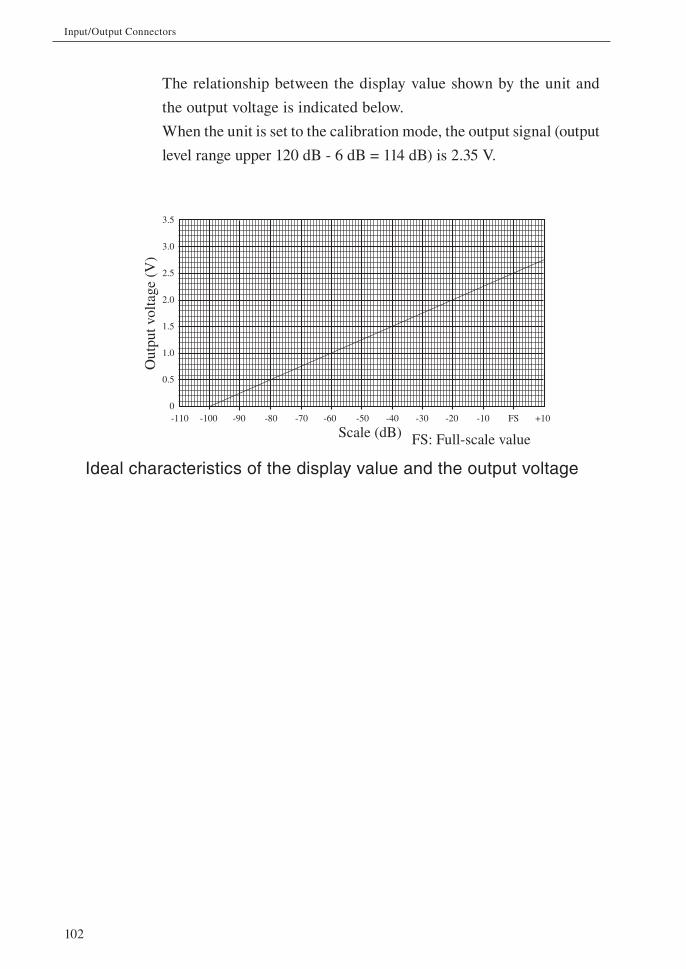
102
Input/Output Connectors
Out
putv
olta
ge(V
)
Scale (dB) FS: Full-scale value
3.5
3.0
2.5
2.0
1.5
1.0
0.5
0-110 -100 -90 -80 -70 -60 -50 -40 -30 -20 -10 FS +10
The relationship between the display value shown by the unit and
the output voltage is indicated below.
When the unit is set to the calibration mode, the output signal (output
level range upper 120 dB - 6 dB = 114 dB) is 2.35 V.
Ideal characteristics of the display value and the output voltage

103
Input/Output Connectors
I/O connector
The I/O connector is located at the bottom of the unit and used for RS-232C
communication or comparator output.
To use this connector for RS-232C communication and connect to a printer,
see page 21. For comparator output, see page 32.
Note
The RS-232C communication and the comparator output cannot be used at the same time.
Comparator output
Comparator outputapprox.480
Tr
Time
Signal output continues for 1 secondafter level falls below threshold
1 s
Open-collector
Maximum applied voltage: 24 V DC
Maximum drive current: 60 mA DC
Peak power output: 300 mW
Comparatorlevel
Comparator signal
Internal circuitof the unit
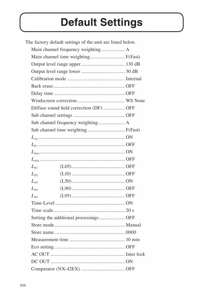
104
Default Settings
The factory default settings of the unit are listed below.
Main channel frequency weighting .................. A
Main channel time weighting ........................... F(Fast)
Output level range upper .................................. 130 dB
Output level range lower .................................. 30 dB
Calibration mode ............................................. Internal
Back erase ........................................................ OFF
Delay time ....................................................... OFF
Windscreen correction ..................................... WS None
Diffuse sound fi eld correction (DF) ................. OFF
Sub channel settings ........................................ OFF
Sub channel frequency weighting ..................... A
Sub channel time weighting ............................. F(Fast)
Leq .................................................................... ON
LE ..................................................................... OFF
Lmax .................................................................. ON
Lmin .................................................................. OFF
LN1 (L05) ......................................... OFF
LN2 (L10) ......................................... OFF
LN3 (L50) ......................................... ON
LN4 (L90) ......................................... OFF
LN5 (L95) ......................................... OFF
Time-Level ...................................................... ON
Time scale ........................................................ 20 s
Setting the additional processings .................... OFF
Store mode ....................................................... Manual
Store name ....................................................... 0000
Measurement time ........................................... 10 min
Eco setting ....................................................... OFF
AC OUT .......................................................... Inter lock
DC OUT .......................................................... ON
Comparator (NX-42EX) .................................. OFF

105
Default Settings
Communication interface ................................. OFF
Baud rate .......................................................... 9600 bps
Backlight auto off ............................................ 30 s
Backlight brightness ........................................ 2
LCD auto off at auto store ................................ OFF
Index ................................................................ 1
Battery type ..................................................... Alkaline
Touch panel lock .............................................. OFF
When you turn power to the unit on while holding down the START/STOP key,
the unit will be initialized to the above settings. When wishing to set the unit
to the factory default values, select [menu] [system – Read/Save Setting]
[Load Default Settings] and then press the MENU/ENTER key (see page 107).
The time, language and store data are not initialized.

106
Setup Files
Resume function
When power to the unit is turned on, the measurement screen appears. The
settings active at this point are the same as were selected before the unit was
last turned off (resume function).
Note
When the unit is started while a start up fi le exists in the internal memory, the start up fi le load function (see the following description) will be executed fi rst.
Loading a start up fi le at startup
When the unit is turned on while a start up fi le exists in the internal memory,
a screen asking whether or not to start the unit with the start up fi le is dis-
played (start up fi le load function).
Selecting [Yes] at the screen will load the start up fi le.
Selecting [No] at the screen will cause the resume function to re-establish
the same settings as before the last time the unit was turned off.
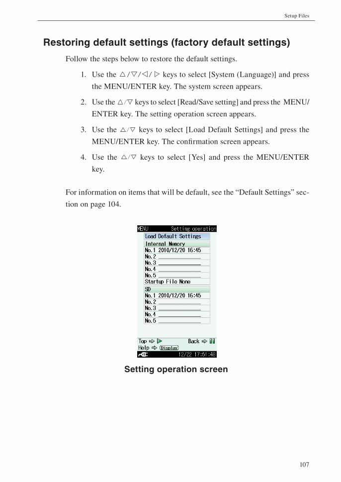
107
Setup Files
Restoring default settings (factory default settings)
Follow the steps below to restore the default settings.
1. Use the keys to select [System (Language)] and press
the MENU/ENTER key. The system screen appears.
2. Use the keys to select [Read/Save setting] and press the MENU/
ENTER key. The setting operation screen appears.
3. Use the keys to select [Load Default Settings] and press the
MENU/ENTER key. The confi rmation screen appears.
4. Use the keys to select [Yes] and press the MENU/ENTER
key.
For information on items that will be default, see the “Default Settings” sec-
tion on page 104.
Setting operation screen

108
Setup Files
Using setup fi les
Setup fi les enable the following functions.
• Establish settings quickly and precisely by loading from a fi le prepared
beforehand and stored on internal memory or SD memory card
• Return settings that were accidentally changed to the previous condition
by loading from a fi le stored on internal memory or SD memory card
Setup fi les can be saved up to fi ve in the internal memory of the unit and up
to fi ve in an SD memory card.
Saving the current settings
1. Use the keys to select [System (Language)] and press
the MENU/ENTER key. The system screen appears.
2. Use the keys to select [Read/Save setting] and press the MENU/
ENTER key. The setting operation screen appears.
3. Use the keys to select the desired number and press the MENU/
ENTER key. The setting fi le processing screen appears.
4. Use the keys to select [Save the setting] and press the MENU/
ENTER key. The confi rmation screen appears.
5. Use the keys to select [Yes] and press the MENU/ENTER key.
The current settings is saved in the selected number.
Note
The recall screen settings are not saved. Only the settings of the immediately preceding measurement screen will be saved.

109
Setup Files
Loading a setup fi le
Note
When you load settings from a fi le, the current set-tings will be overwritten. If necessary, you should save the current settings before loading a new set
of settings.
1. Use the keys to select [System (Language)] and press
the MENU/ENTER key. The system screen appears.
2. Use the keys to select [Read/Save setting] and press the MENU/
ENTER key. The setting operation screen appears.
3. Use the keys to select the desired number and press the MENU/
ENTER key. The setting fi le processing screen appears.
4. Use the keys to select [Load the setting] and press the MENU/
ENTER key. The confi rmation screen appears.
5. Use the keys to select [Yes] and press the MENU/ENTER key.
The fi le contents of the selected number will be refl ected to the set-
ting of the unit.
Deleting a setup fi le
1. Use the keys to select [System (Language)] and press
the MENU/ENTER key. The system screen appears.
2. Use the keys to select [Read/Save setting] and press the MENU/
ENTER key. The setting operation screen appears.
3. Use the keys to select the desired number and press the MENU/
ENTER key. The setting fi le processing screen appears.
4. Use the keys to select [Delete] and press the MENU/ENTER
key. The confi rmation screen appears.
5. Use the keys to select [Yes] and press the MENU/ENTER key.
The fi le of selected number is deleted.
110
Setup Files
Copying a setup fi le
1. Use the keys to select [System (Language)] and press
the MENU/ENTER key. The system screen appears.
2. Use the keys to select [Read/Save setting] and press the MENU/
ENTER key. The setting operation screen appears.
3. Use the keys to select the desired number and press the MENU/
ENTER key. The setting fi le processing screen appears.
4. Use the keys to select [Copy] and press the MENU/ENTER
key.
5. Select a destination on the screen using the keys and then press
the MENU/ENTER key. The confi rmation screen appears.
6. Use the keys to select [Yes] and press the MENU/ENTER key.
The fi le of selected number is copied.

111
Setup Files
Setting a start up fi le
When a setting is saved in a start up fi le, the unit can be started using the
setting.
1. Set the unit to the intended condition, so that measurement parameters
and other settings are as desired.
2. Use the keys to select [System (Language)] and press
the MENU/ENTER key. The system screen appears.
3. Use the keys to select [Read/Save setting] and press the MENU/
ENTER key. The setting operation screen appears.
4. Use the keys to select [Startup File None] and press the MENU/
ENTER key. The setting fi le processing screen appears.
Note
When a start up fi le has already been saved, select [Startup File Data is available]
5. Use the keys to select [Save the setting] and press the MENU/
ENTER key.
When “The setting was saved” is displayed, it means that the saving
process has been completed.
Note
When selecting [Startup File Data is available] to overwrite the data, select [Yes] on the confi rmation screen.
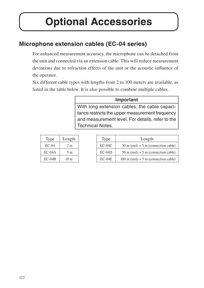
112
Optional Accessories
Microphone extension cables (EC-04 series)
For enhanced measurement accuracy, the microphone can be detached from
the unit and connected via an extension cable. This will reduce measurement
deviations due to refraction effects of the unit or the acoustic infl uence of
the operator.
Six different cable types with lengths from 2 to 100 meters are available, as
listed in the table below. It is also possible to combine multiple cables.
ImportantWith long extension cables, the cable capaci-tance restricts the upper measurement frequency and measurement level. For details, refer to the Technical Notes.
Type Length Type Length
EC-04 2 m EC-04C 30 m (reel) + 5 m (connection cable)
EC-04A 5 m EC-04D 50 m (reel) + 5 m (connection cable)
EC-04B 10 m EC-04E 100 m (reel) + 5 m (connection cable)

113
Optional Accessories
Printer DPU-414
Data stored in the memory of the unit and on SD memory card can be printed
out on a printer. You can also produce hard copy of measurement screens.
(The printer, printer paper, and printer cable are options.)
To print measurement data, turn the unit and the printer on and set the printer
to the online state. The steps described in the chapter “Preparations” (page
9) should be completed.
For details about printer operation, refer to the documentation supplied with
the printer.
Printing a measurement screenThe steps for printing hard copy of a measurement screen are described
below.
1. Press the MENU/ENTER key to bring up the menu list screen.
2. Use the keys to select [Save/Print] and press the MENU/
ENTER key. The save/print screen appears.
3. Use the keys to select [Print] and press the MENU/ENTER
key. The screen is printed.
To cancel the process, select [Cancel] and press the MENU/ENTER
key.

114
Optional Accessories
Printing stored dataThe steps for printing hard copy of a stored data are described below.
1. Press the MENU/ENTER key to bring up the menu list screen.
2. Use the keys to select [Recall] and press the MENU/
ENTER key. The recall screen appears.
3. Use the keys to select the desired data and press the
MENU/ENTER key. The data processing screen appears.
4. Use the keys to select [Confi rm the
data] and press the MENU/ENTER key.
The stored data screen appears.
5. When the stored data screen is displayed,
pressing the MENU/ENTER key brings
up the menu list screen for stored data.

115
Optional Accessories
6. Use the keys to select [Save/Print] and press the MENU/
ENTER key. The save/print screen appears.
7. Use the keys to select [Range Setting Print] and press the
MENU/ENTER key. The range setting print screen appears.
8. Set the [Start Address] and [End Address] and then select [Print
Execution] and press the ENTER key. The data within the area
specifi ed by the entered addresses will be printed
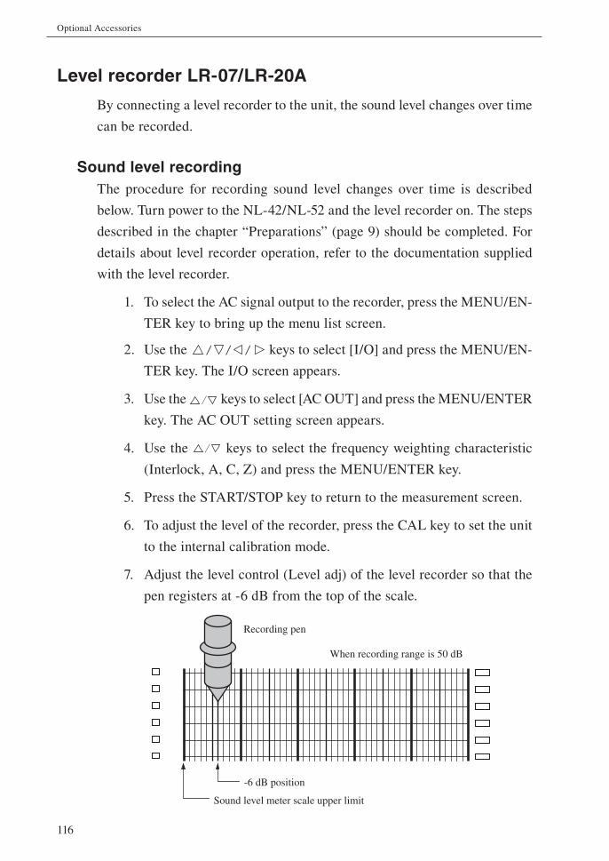
116
Optional Accessories
Level recorder LR-07/LR-20A
By connecting a level recorder to the unit, the sound level changes over time
can be recorded.
Sound level recordingThe procedure for recording sound level changes over time is described
below. Turn power to the NL-42/NL-52 and the level recorder on. The steps
described in the chapter “Preparations” (page 9) should be completed. For
details about level recorder operation, refer to the documentation supplied
with the level recorder.
1. To select the AC signal output to the recorder, press the MENU/EN-
TER key to bring up the menu list screen.
2. Use the keys to select [I/O] and press the MENU/EN-
TER key. The I/O screen appears.
3. Use the keys to select [AC OUT] and press the MENU/ENTER
key. The AC OUT setting screen appears.
4. Use the keys to select the frequency weighting characteristic
(Interlock, A, C, Z) and press the MENU/ENTER key.
5. Press the START/STOP key to return to the measurement screen.
6. To adjust the level of the recorder, press the CAL key to set the unit
to the internal calibration mode.
7. Adjust the level control (Level adj) of the level recorder so that the
pen registers at -6 dB from the top of the scale.
Sound level meter scale upper limit
-6 dB position
Recording pen
When recording range is 50 dB

117
Optional Accessories
8. Press the CAL key once more to return the NL-42/NL-52 to the
measurement mode.
9. Set the time weighting characteristic at the level recorder.
10. Set the [Output Level Range Upper] and [Output Level Range Lower]
on the [Display] screen.
The [Output Level Range Upper] setting of the NL-42/NL-52 becomes
the scale upper limit of the level recorder.

118
Optional Accessories
Program options
The unit can make use of a range of program options.
For details on usage, refer to the documentation supplied with the respective
program.

119
Specifi cations
Applicable standards
NL-42 IEC 61672-1:2002 Class 2
ANSI S1.4-1983 Type 2
ANSI S1.4-1985 Type 2
ANSI S1.43-1997 Type 2
JIS C 1509-1:2005 Class 2
NL-52 IEC 61672-1:2002 Class 1
ANSI S1.4-1983 Type 1
ANSI S1.4-1985 Type 1
ANSI S1.43-1997 Type 1
JIS C 1509-1:2005 Class 1
NL-42/NL-52 CE marking, WEEE Directive, Chinese RoHS
Measurement function Simultaneous measurement of all items, using selected
time weighting and frequency weighting
Processing Sound level Lp
Equivalent continuous sound level Leq
Sound exposure level LE
Maximum sound level Lmax
Minimum sound level Lmin
Percentile sound level LN (1 to 99, 1-incre-
ment steps, max.
5 values, calcu-
lated from Lp or
Leq,1sec)

120
Specifi cations
Additional processing
One of the following measurements can also be selected
for simultaneous processing with main processing.
Equivalent continuous C-weighted sound level
LCeq
C-weighted peak sound level LCpeak
Z-weighted peak sound level LZpeak
Impulse equivalent continuous sound level
LAIeq
Tact-max A-weighted sound level LAtm5
The frequency response of additional processing is
associated with that of sub channel. Therefore, either
LCeq or LCpeak (LZpeak) can be selected when the sub
channel has C-weighting (Z-weighting).
Processing period
The processing period can be selected from 10 sec, 1
min, 5 min, 10 min, 15 min, 30 min, 1 h, 8 h, 24 h and
manually selected arbitrary time.
Arbitrary period of time up to 24 h can be set manu-
ally.
For LN, 10 seconds or longer measurement time will
be displayed.
Microphone
NL-42 NL-52
Model: UC-52 UC-59
Sensitivity: -33 dB -27 dB
Preamplifi er
NL-42 NL-52
Model: NH-24 NH-25

121
Specifi cations
Measurement range A-weighting: 25 dB to 130 dB
C-weighting: 33 dB to 130 dB
Z-weighting: 38 dB to 130 dB
C-weighted peak sound level: 55 dB to 141 dB
Z-weighting peak sound level: 60 dB to 141 dB
Inherent Noise NL-42 NL-52
A-weighting: 19 dB or less 17 dB or less
C-weighting: 27 dB or less 25 dB or less
Z-weighting: 32 dB or less 30 dB or less
Total range 25 dB to 138 dB (A weighting, 1 kHz)
Linear operating range
All-pass (A-weighting) 113 dB
Measurement frequency range
20 Hz to 8 kHz (NL-42)
20 Hz to 20 kHz (NL-52)
Reference frequency 1 kHz
Reference sound pressure level
94 dB
Frequency weighting A, C, Z
Time weighting F (Fast), S (Slow)
Bar graph display range
Max. 110 dB (20 to 130 dB)
Bar graph range switch
Upper and lower limits of the bar graph can be set in
increments of 10 dB.
Display full scale Upper limit of bar graph display
RMS detection circuit
Digital processing method
Sampling interval Lp, Leq, LE, Lmax, Lmin, Lpeak: 20.8 µs
(Sampling frequency: 48 kHz)
LN: 100 ms

122
Specifi cations
Calibration
Electrical calibration with signal from built-in oscillator
Calibration frequency: 1 kHz
Calibration sound pressure level: 94 dB
Acoustic calibration using sound calibrator NC-74
Calibration frequency: 1 kHz
Calibration sound pressure level: 94 dB (NL-52)
93.9 dB (NL-42)
Correction functions
Windscreen correction
Reduces infl uence of mounted windscreen on frequency
response characteristics.
Turning on/off the correction function is done from
the menu screen.
* The unit complies with IEC 61672-1 and JIS C 1509-1
with windscreen mounted.
Diffuse sound fi eld correction
Corrects frequency response to meet the standard (ANSI
S1.4) in diffuse sound fi eld.
Turning on/off the correction function is done from
the menu screen.
Delay time Sets a delay in starting measurement from the point of
pressing the Start key.
Setting range: The delay time is selected from OFF,
1, 3, 5 or 10 sec and set to it.
Previous data removal function (Back-erase function)
When measurement is paused with the Pause key, the
data of some seconds from the point of pressing the
Pause key are excluded from processing.
Setting range: The time is selected from OFF, 1, 3
or 5 sec and set to it.

123
Specifi cations
Display Backlit semitransparent color TFT LCD display
WQVGA
(400 × 240 dots)
* LCD is equipped with the touch panel (capacitance
type) control function.
Bar graph update frequency
100 ms
Numeric display update frequency
1 s
Manual store Measurement result and measurement start time are
stored manually on an address to address basis.
Data store capacity
Up to 1000 data sets in the internal memory
* External memory depends on the card capacity (only
the performance of Rion genuine cards is guaran-
teed).
Data recall Allows viewing of store data.
Setup memory Up to fi ve setup confi gurations can be saved in the
internal memory for later recalls.
The unit can be started using the setting fi le stored in
the internal memory beforehand.
Output
DC output Outputs DC signals with the frequency weighting se-
lected for processing.
DC output: 2.5 V, 25 mV/dB at display full-
scale point
Output impedance: approx. 50 Ω
Load impedance: 10 kΩ minimum
AC output Outputs AC signals with the frequency weighting se-
lected for processing.
Output voltage: 1 Vrms (rms) at display full-scale
point
Output impedance: approx. 600 Ω
Load impedance: 10 kΩ minimum
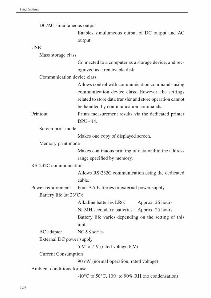
124
Specifications
DC/AC simultaneous output
Enables simultaneous output of DC output and AC
output.
USB
Mass storage class
Connected to a computer as a storage device, and rec-
ognized as a removable disk.
Communication device class
Allows control with communication commands using
communication device class. However, the settings
related to store data transfer and store operation cannot
be handled by communication commands.
Printout Prints measurement results via the dedicated printer
DPU-414.
Screen print mode
Makes one copy of displayed screen.
Memory print mode
Makes continuous printing of data within the address
range specified by memory.
RS-232C communication
Allows RS-232C communication using the dedicated
cable.
Power requirements Four AA batteries or external power supply
Battery life (at 23°C):
Alkaline batteries LR6: Approx. 26 hours
Ni-MH secondary batteries: Approx. 25 hours
Battery life varies depending on the setting of this
unit.
AC adapter NC-98 series
External DC power supply
5 V to 7 V (rated voltage 6 V)
Current Consumption
90 mV (normal operation, rated voltage)
Ambient conditions for use
-10°C to 50°C, 10% to 90% RH (no condensation)

125
Specifications
Water and dust resistant performance
IP Rating IP 54 (except microphone unit)
Protection against harmful dust and water splashing
from any direction.
Dimensions Approx. 250 × 76 × 33 mm
Weight Approx. 400 g
Supplied accessories
Storage case NL-42-025 1
Windscreen WS-10 1
Windscreen fall prevention rubber 1
Hand strap VM-63-017 1
Size AA alkaline batteries LR6 4
Instruction manuals (CD-ROM)
(Instruction Manual, Serial Interface Manual, Technical Notes)
1
Description for IEC 61672-1 1

126
Specifi cations
Optional accessories
SD Card 512 MB SD-512M
SD Card 2 GB SD-2G (2 GByte)
AC adapter (100 V to 240 V) NC-98 series
Battery pack BP-21
Microphone extension cable EC-04 series
BNC - Pin output code CC-24
Comparator output cable CC-42C
Printer DPU-414
Printer cable CC-42P
RS-232C serial I/O cable CC-42R
USB cable (A - mini B)
Sound calibrator NC-74
Windscreen for outdoor WS-15
Sound level meter tripod ST-80
Data recorder DA-20/DA-40
Level recorder LR-07/LR-20A
Data management software for environmental measurement
AS-60
Waveform analysis software CAT WAVE
Program option
Extended Function Program NX-42EX
Waveform Recording Program NX-42WR

127
Specifications
Unit: mm
Dimensional Drawings
33
Bottom view
76250
Front view Side view Rear view

No. 55530 11-03