nm100 series page system installation read and save these
TRANSCRIPT

model Nm100WH
Page �
cautioN
WarNiNg
to reduce tHe risk of fire, electric sHock, or iNjury to persoNs, observe tHe folloWiNg:
1. Readall instructionscarefullybefore installingorusingtheNM100System.
2. TheNM100mustbeinstalledbyaqualifieddealerorinstaller,andmustconformtoalllocalbuildingandelectricalcodes.
3. Forcontinuedprotectionagainstriskoffirereplacethefuseinthepowerswitchmoduleonlywiththesametype3Amp,250Voltfuse.
4. AdheretoallwarningsontheNM100andintheseinstructions.Followalloperatingandinstallationinstructions.
Nm100 seriessystem iNstallatioN
read aNd save tHese iNstructioNs
tHese iNstallatioN iNstructioNs are for use by qualified persoNNel oNly. to reduce tHe risk of electric sHock, do Not perform aNy serviciNg otHer tHaN tHat coNtaiNed iN tHe operatiNg iNstructioNs uNless you are qualified to do so.
• Do not attempt to service the NM100 yourself as openingor removingcoversmayexposeyou todangerousvoltageor other hazards. Refer all servicing to qualified servicepersonnel.
The lightning flash with arrowhead symbol within anequilateral triangle is intended to alert the user to thepresence of uninsulated “dangerous voltage” within theproduct’senclosure thatmaybeofsufficientmagnitude toconstituteariskofshocktopersons.
The exclamation point within an equilateral triangle isintended to alert the user to the presence of importantoperating and maintenance (servicing) instructions in theliteratureaccompanyingtheproduct.
• Locatethesystemawayfromheatsourcessuchasradiators,heatregisters,stoves,orotherheatproducingproducts.
• Do not locate the NM100 master or remote stations in anoutsidewall.
• DonotexposetheNM100tomoisture.Doingsocancreatefireorshockhazardsandvoidthewarranty.
• Donotplace theNM100masteror remotestations inanywallcavitywithanyotherelectricalwiringinthecavity.
• InstalltheNM100systemafterapplicationofthewallcoveringmaterial.
• Do not expose the outdoor remote station speakers tosignificantwatercontact.Theoutdoorremotespeakersareweatherproof but not waterproof. Continuous direct waterexposurewillcausesystemproblems.
• Do not connect a remote or door station wire if you areunsureofitsterminatingpoint.Connectingadoorstationtoaremotestationmayresultinsystemdamage.
• Doensurethatallrough-ininstructionshavebeenfollowedbeforepowerisappliedtotheNM100system.
• Donotsplicecables.Splicesareunreliableanddefeatthesignalisolationpropertiesofthecable.
• Donotattachdevicesunauthorizedforusewiththissystem.Authorizeddevicesinclude:
Audiocomponentsconnectedviaalinelevelinput
NC3006-discplayer
• Ifextracableshavebeenrun for futurespeakeradditions,caremustbetakentoensurethesecablesarenotconnectedtotheNM100masterunit.Un-terminatedcables(nostation)connected to the NM100 master may cause electricalfeedbackthatwilldamagethemasterstation.
• Do not over-tighten the screws for the remote stations ormasterastheplasticfacepanelsmaycrackorstripout.
• Use only NuTone certified replacement parts and havetheminstalledbyaNuTonedealerorinstaller.Unauthorizedsubstitutions can result in fire, electric shock, or otherhazards.
• Upon completion of any service or product repair, havethedealerorinstallerconductasafetychecktoensurethesystemisinproperoperatingcondition.
• UseonlyadampclothtocleantheNM100masterandremotestations.Donotuseliquidcleanersoraerosolcleaners.
cautioN: WiriNg• Aqualifiedelectricianmustruna120VAClinetotheNM100
retrofittransformers.
• Individualwirerunsshouldnotexceedmorethan350FEETofwirefromanysingleremotestationtotheNM100masteror1000totalfeetfortheentiresystem.
• Label all wiring runs. Connecting the wires to the NM100master,remotestationordoorstationsincorrectlymayresultinsystemdamage.
• Run a single cable from the master unit location to eachremotestationanddoorstationina“homerun”fashion.Donotloopcablefromoneremotestationtoanother.
• Donotstaplecables.Staplescauseshorts.
• Donotsplicecables.Splicesareunreliableanddefeatthesignalisolationpropertiesofthecables.
• Do not run electrical wires through the rough-ins. If youencounter120VACwiresrunningthrougharough-induringa retrofit youmusthaveaqualifiedelectrician rerun thosewiresaroundtherough-in.
model Nm100WH
Page �• Keepcablesatleast18inchesfromfluorescentlightfixtures,
dimmer controls, and all other wiring. This includes ACwiring,securitycable,cordlessphoneunits,andothercontrolwires.Thesecancausea“hum”or“buzzing”sound.
• Keep cables away from objects such as heating and airconditioningducts,metalconstructionplates,andanythingelsewithsharpedgesthatcandamagethecables.
cautioN: remote statioN rougH-iNCareful consideration should be used when determining thelocationoftheremotestationsandmaster.Sincethisisaretrofitsystemyouwillnotbeabletocontrolthelocationoftheexistingsystem.Butpleasefollowtheguidelinesbelowifyouinstallanynewlocations:
• Donotinstallremotestationsinreturnairducts.
• Do not install remote stations in exterior walls. Insulationmaterials will change speaker range and efficiency.Temperaturechangesinthewallwillreducespeakerlife.
• Do not install remote stations in saunas. They will notwithstandtheextremeheatandmoisture.
• Donotinstallremotestationsinstudcavitieswithotherwiringorappliances.
• Do not install remote stations within 18” of dimmers,fluorescent light fixtures, security wiring, cordless phoneunits,andothercontrolwiring.
• Donotinstallremotestationswithin10feetofotherremotestationsortheNM100masterunit.Thiswillcauseacousticfeedback.
• Do not install remote stations in stud cavities with otherremotestationsor theNM100masterunit.Thiswill causeacousticfeedback.
• DonotinstallremotestationsfacingotherremotestationsortheNM100masterunit.Thiswillcauseacousticfeedback.
• Domakesureallrough-insarelevelandorientedasshownintheseinstructions.
iNstallatioNDesigned to update older intercom systems, theNM100 is awhole-house music communications system that uses yourexistingintercom3or4conductorsystemwire.Itisdesignedtoprovideyearsofenjoymentandservicetothehomeowner.
Toensurethatthehomeownerreceivesthehigh-qualitymusicandvoicereproductionthatthesystemisdesignedtodeliver,itisimportantthateachstepoftheinstallationbedonecarefully.In theevent youneed troubleshooting installation assistance,pleasecallourtechnicalstaffat1-888-336-6151.
Prior to installing the NM100 system, read and observe theImportantSafetyInstructions.
TheNM100retrofitinstallationiscompletedusingthefollowingsteps:
• Developthejobestimate
• Removaloftheoldintercomsystem
• InstalltheNWH300orNWH300Crough-in
• Replace the remote stations (Note: do not remove theexistingremotestationrough-ins)
• InstalltheoptionalNC300player
• Install the NM100 master and make all remote stationconnections
• Testthesystem
ThefollowingtoolsarerequiredfortheNM100installation.Theuseoftheseorothertoolsisdependentontheexistingintercomsysteminstallation:
• #2Phillipsscrewdriver
• Wirestripper/cutter
• Tapemeasure
• Level
• TinSnips
• DigitalMultimeter(dmm)
• Small(orprecisionsize)Philips/Flatheadscrewdriver
• Powerdrillwith1”auger
• SmallCrowbar
• LargeFlatheadscrewdriver
• Rubbermallet
• Extensioncord
• Woodchisel
• Drywallsaw
Youmaynotneedtouseallthesetoolsoneachinstallbuthavingthemhandywillmaketheoverallinstallationprocesseasier.
develop tHe job estimate
It is critical that youdetermine the complexity of each retrofitinstallation prior to developing the job estimate. It is hard topredictall theuniquesituationsyouwillencounter inthefield.For this reason NuTone recommends you visit each retrofitsitepriortodevelopingajobestimateandorderingequipment.Duringthisonsitevisititisrecommendedthatyoucompletetheitemslistedbelow:
• Determine the model number and manufacturer of theexistingintercomsystem.
• Countthenumberofremotestationsanddoorstations.
• Determine if thedoorstationsandoutdoorremotestationsaresurfaceorflushmount.
• Removethemasterfromthewalltoseeifanynon-standardinstallationsituationsmightexist,including:
-Electricalrunningthroughtherough-in.
-Telephonewiresrunningthroughtherough-in.
- Stud spacing that varies from a standard 16” on centerspacing
-Thetypeofwireusedforindoorremote,doorandoutdoorremotestationruns(NuTone,M&Sorothersuchastelephonewire). If you encounter non-standard wire contact ourTechnicalSupportteamat1-888-336-6151forassistance.
-Aremotetransformer
-Aremotedoorchime

model Nm100WH
Page �
Theanswerstotheaboveinformationwillhelpyouscope,priceandinstalltheretrofitsystem.
removiNg tHe old system
Prior to removing the existing intercom system make sure allpoweristurnedoffattheintercomlocation.Removethescrewsfrom the intercom master and while removing the intercom,make sure to carefully label each wire with its correspondingroomlocation.Disconnectalltheremotestationanddoorstationwiresfromthemaster.Thencarefullyremovetheexistingwallhousingandtransformers.
If the existing system was not working prior to replacement,checkeachwire runbetween the remotestationsandmasterforshortsandwiringintegrity.Ifoneoftheseremotestationtomasterwirerunshasashort,re-runthatwirepriortoinstallingtheNM100. When replacingNuTone 3wire cable runs, useNuToneIWA3cable.WhenreplacingNuToneorM&S4wirecableruns,useNuToneNW4Scable.
Note: if you encounter 120VAC running through the existingrough-in,haveaqualifiedelectricianreroutethe120VACaroundtherough-in.
Ifyouencounteraremotetransformer,anadditionalelectricalrunmayhavetobemadebyaqualifiedelectriciantopowerthemasterstationand/oroptionalCDplayer.Alsochecktomakesurethattheareaaroundthehousingisclearofanyadditional120VACrunsorotherobstructions.
iNstalliNg tHe rougH-iN
The NWH300 and NWH300C rough-ins are designed for 16”oncenterstuds.Inretrofitapplicationsyoumayencounterstudspacingthatvariesfromthisstandard.UsetheNWH300rough-inwhenyouarereplacinganexistingsystemwithanintercomonlysystem.TheNWH300Crough-in isused forcombinationsystems only that use the NM100 master and the optionalNC3006-discCDplayer.
LocatetheNWH300ortheNWH300Crough-ins.Therough-inmustbepositionedsothatthetransformersareonthebottomoftherough-inasshowninthefigurebelow.
If you are replacing the existing master only system with acombination NM100 master and NC300 CD changer you willhave to cut the rough-in opening larger to accommodate thelarger rough-in. Prior to making the cutout check the studcavity for obstructions or items in the wall that may preventthe transformers from fitting in the wall. The NWH300 andNWH300Ctransformersdropinfromthebottomoftherough-in.Pleaserefertothenextfigureforrough-inplacement.
Connecttheexisting,dedicated120VAC/60Hzlinewithgroundconnection from the power panel to the rough-in as shownbelow.TheNM100requiresadedicatedpowersourcetoassurenointerferencefromotherequipmentcausedbyloopedpowercircuits.Thegroundisnecessaryforproperradioreception.
Placetransformerenclosurefromtheinsideofthewallhousinginto the transformer enclosure opening at the bottom of therough-inasshownbelow.Donotrunthe120VACthroughthe
model Nm100WH
Page �
replaciNg tHe room statioNs
Theremoteanddoorstationsusetheexistingwireandstationrough-inmountingframesorboxes.Toreplacethestation,firstremovetheoldstation.Leavetheexistingremoteordoorstationrough-insinplace.
Afterremovingtheremotestationverifytheintegrityofthewirerun.TheninstallthemountingplatefromtheNF300RWHframe.Aligntheplateonthewalleitherverticallyorhorizontallysothatthescrewholeslineupwiththoseontherough-inorbox.Usealeveltomakesuretheplateislevel.Thereareseveralscrewhole locationson themountingplateso itcanattach tomanyrough-indesigns.Mounttheplatetothewallusingthescrewsprovided.
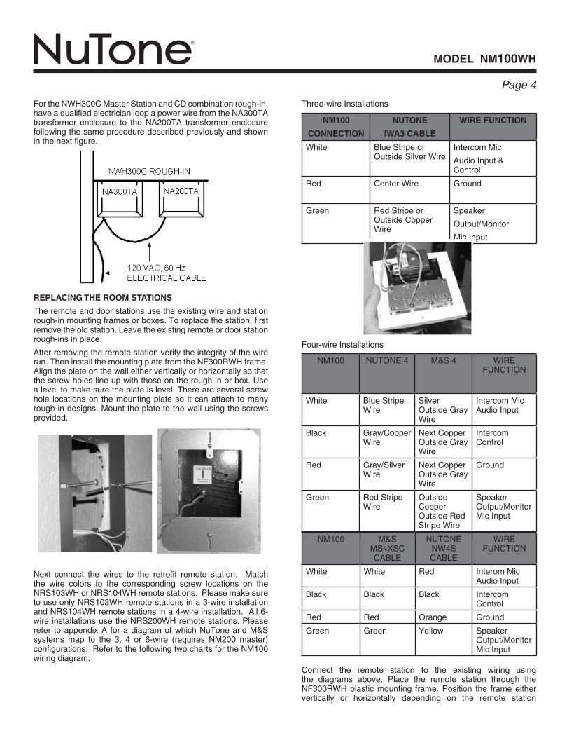
Nm100
coNNectioN
NutoNe
iWa3 cable
Wire fuNctioN
White BlueStripeorOutsideSilverWire
IntercomMic
AudioInput&Control
Red CenterWire Ground
Green RedStripeorOutsideCopperWire
Speaker
Output/Monitor
MicInput
Four-wireInstallations
Connect the remote station to the existing wiring usingthe diagrams above. Place the remote station through theNF300RWHplasticmounting frame.Position the frameeithervertically or horizontally depending on the remote station
Three-wireInstallations
Next connect the wires to the retrofit remote station. Matchthe wire colors to the corresponding screw locations on theNRS103WHorNRS104WHremotestations.PleasemakesuretouseonlyNRS103WHremotestationsina3-wireinstallationandNRS104WHremotestationsina4-wireinstallation.All6-wire installationsusetheNRS200WHremotestations.Pleaserefer toappendixA foradiagramofwhichNuToneandM&Ssystemsmap to the 3, 4 or 6-wire (requires NM200master)configurations.RefertothefollowingtwochartsfortheNM100wiringdiagram:
FortheNWH300CMasterStationandCDcombinationrough-in,haveaqualifiedelectricianloopapowerwirefromtheNA300TAtransformer enclosure to the NA200TA transformer enclosurefollowingthesameproceduredescribedpreviouslyandshowninthenextfigure.
NM100 NUTONE4 M&S4 WIREFUNCTION
White BlueStripeWire
SilverOutsideGrayWire
IntercomMicAudioInput
Black Gray/CopperWire
NextCopperOutsideGrayWire
IntercomControl
Red Gray/SilverWire
NextCopperOutsideGrayWire
Ground
Green RedStripeWire
OutsideCopperOutsideRedStripeWire
SpeakerOutput/MonitorMicInput
NM100 M&SMS4XSCCABLE
NUTONENW4SCABLE
WIREFUNCTION
White White Red InteromMicAudioInput
Black Black Black IntercomControl
Red Red Orange Ground
Green Green Yellow SpeakerOutput/MonitorMicInput

model Nm100WH
Page �
iNstalliNg tHe Nc300 cd cHaNger
ConnecttheaudiocablestotheaudiojacksoftheNC300playerasshowninthefigurebelow.Afterconnectingtheaudiocablesandmaincable,connectthepowercordfromtheNA200TAtransformertothepowerconnectorontheNC300CDchanger.PleaserefertotheinstallationmanualpackedwiththeNC300CDchanger.
EnsuringthatnothingisbetweentheCDplayerandthebackoftherough-in(includingcables),placetheNC300playerintotheloweropeningoftheframesincludingtheNF200CorNF100Cframes.Usethescrewsprovidedtosecuretheunitinplace.
replaced. Place the remote station into the rough-in ring andaligntheframewiththeremotestation.Usethescrewsprovidedwiththeremotestationtoscrewtheremotestationandframeintoplace.Theholesintheremotestationalignwiththeholesinthemountingplate.Theremotestationkeepstheplasticframeinplaceonthewall.
Note that the plastic frames are paintable. Please prime theplastic first and then apply standard room paint. The whiteplasticmayrequiretwocoatsofpainttogetfullcoverage.Itisrecommended thatyoupaint the frameprior tomounting it tothewall.
important: please label all cables at both ends. incorrectly connecting cables to the master, remote stations or door stations could result in system damage.
outdoor remote statioNs
Do not remove the existing outdoor remote station rough-in.TheNuTone retrofitsystem isdesigned tofit into theexistingenclosure.Itisimportanttonotethattheoutdoorremotestationsareweatherresistantnotwaterproof.Thesestationsshouldnotbelocatedinanareathatisindirectlineofwaterfromsprinklers,rainorotherdevicessuchaspowerwashers.
PleaseusetheNF300PWHframeinoutdoorandhighsunareas.TheNF300PWHplasticisdesignedtowithstandsunandresistfading.Ifapatiorequiresasurfacemountapplication,usetheNRKS200PWH.Thisisasurfacemountboxandcoverthatwillsupport theNPS200WH,NPS103WHorNPS104WHoutdoorremotestations.
To install an outdoor remote station follow the instructionspresentedearlierforindoorremotestations.
door statioNs
Remove the old door station but do not remove the rough-inbox or surface mount box. When replacing a NuTone doorstation you must use the NF300DWH mounting frame. TheM&SdoorstationsetsintheNF300DWHframeandthescrewsattach to the existing rough-in. Connect the door station withthecorrespondingcolorwires.Screw thedoorstationordoorstationwithNF300DWHframeintotherough-inbox.
exterNal music source
TheNM100retrofitsystemsupportstheuseofexternalmusicsources.Youcanuseanexistingconnectionorrunanewwiretosupportlocalsourceconnection.Toinstallanewlocalsourcefollowthestepsdetailedinthefollowingparagraphs.
ChoosealocationfortheIA30WHaudiowallplatethatwillbeeasilyaccessibletothesourcesthataretobeconnectedtothesystem(closetothereceiver,TVorDVDplayerforexample).Note: the external source wire run to the NM100 must notexceed50feet.
At this location, attach a single gang box included in theIR30Krough-intoawallstudatacenterheightofnormalwalloutlets.Usea lowvoltageplaster ring inexistingconstructioninstallations.
Makesurethesinglegangboxextendspastthewallstudandinto the roomso itwill be flushwith the sheetrockwhen it isapplied.RuntheRedandBlackshieldedaudiocables(includedintheIR30K)fromthemasterunitlocationtotheIA30WHaudiowallplatelocation.Connectthecables.
iNstalliNg tHe cHime module
InstalltheNA3003CorNA3008Coptionalchimemoduleintherough-inbypressingthechimemoduleoverthe4plasticstandoffsattachedtotherough-inasshowninthefollowingfigure.Refertotheinstructionsshippedwiththechimemodule.

model Nm100WH
Page �
Placethejumpersyoujustdisconnectedinthe4-wirepositionshowninthenextfigure.
Suspendthemasterunitfromtherough-inbyloopingthesupportwireassembly(thickgreenwire)overthehookatthetopoftherough-in.Becarefulnottodamagethewallsurface.
Pluginthemodularchimeplugtothe4pinconnectorlabeledasCHIMEontheNM100masterunitasshowninthenextfigure.
If theNM100systemhasmore than9 remotestations,someremote selector switches will control two remote stations.ConnecteachGreenwire(exceptpatio/outdoorremoteGreen)toasinglegreenterminalonthemaster.EachnumberedGreenterminalcorrespondstoaremotestationselectorswitch.Note:Nomore than2Greenwirescanbeconnected toanyGreenterminal and not to exceed 15 speakers for the 4-wire or 13speakers for the 3-wire system. This limitation does includeremotecontrolsandvolumecontrolsbutnotdoorstations.ThestationlocationcanbemarkedontheinsideofthedooraccesspanelontheleftsideoftheNM100master.
Connect thegreenwire(s) from theoutdoor remote station(s)tothePatiogreenterminal.ConnecttheoutdoorremoteBlackwire(s)tothepatioBlackterminal.Note:Onlytwooutdoorremotestationscanbeconnectedto thepatio terminals.Connect theRedwirewiththeotherRedwirestotheRedterminal.ConnecttheWhitewirewiththeotherWhitewirestotheWhiteterminal.Refertothefigureshownbelowforwireplacement.
Connect the red and black wires of the door station cables(NW4S) to the red and black door station terminals on theNM100master as shown in thenext figure. Whenusing theNW4Sshieldedwire,insulatethebarewiresusingsomeofthejacketmaterialtopreventshortingtothecircuitboard.Connectthiswire to terminal labeledshield. ConnectallorangewiresfromthedoorstationstothecommonterminalontheNA3003CorNA3008Cchimemodule.Connecteachyellowwiretoanotesleectionterminal.(Donotconnectmorethanoneyellowwirepernoteterminal).
iNstalliNg tHe Nm100
TheNM100shipsconfiguredfora3-wireretrofitsystem.Ifyouarereplacinga4-wiresystemyoumustchangethejumpersetupontheNM100master.Thejumperchangemustbecompletedbeforeanycablesareconnected.Tochangethe jumpers justpullthemofftheexistingconnectionsshowninthenextfigure.

model Nm100WH
Page �
3. Connectabarejumperwire(a22gaugespeakerwireworkswell)betweentheS3andS4terminals.
Follow the steps below to attach a separate AM/FM antennasystem with 300 Ohm FM twin lead and orange AM antennawire:
1. Connect the FM twin leads to terminal S1 and S2 on theboard
2. ConnecttheAMantenna(orangewire)toterminalS4
3. TerminalS3isnotusedinthisconfiguration
Followthestepsbelowtoconnectasingleorangewireantennasystem:
1. Connect the orange wire to either S1 or S2. Note do notconnectthewiretobothS1andS2doingthiswillshortouttheFMantennasignal.
2. Connectabarejumperwire(a22gaugespeakerwireworkswell)betweentheS3andS4terminals.
door release optioNs
ThedoorreleaseoptionisadrycontactclosureprovidedbytheNM100master.Thisdrycontact israted24Volt/2Amps.Thesampleapplicationsbelowrepresentsomeusesofthisoption.However, only one application can be used in any NM100systematatime.
door or gate release mecHaNism
Runasinglelineof18gaugesolidcopper,twistedpairapprovedlowvoltagecablefromtheNWH300orNWH300Crough-intothedoorreleasemechanism.Connectthetwowiresfromthe18gaugesolidcoppercabletothetwowireterminalsofthedoorreleasemechanism.
Connect the optional NC300 player RCA cables and controlwire. Seeadditional instructionspackedwith theNC300CD
Runanothersingle lineof18gaugesolidcopper, twistedpairapproved low voltage cable from the NWH300 or NWH300Crough-in location toagangboxnext toa120VAC receptaclewheretheremotedoor/gatereleasepowertransformerwillbepluggedin.Labelandsecurecablesattherough-in.
changer.
coNNectiNg tHe aNteNNa
Separatetheintercomcablesfromtheantennaleads,ifgroupedtogether the intercom cables can shield the antenna leadsresultinginpoorradioreception.Keeptheantennaleadsawayfrom metal ductwork and aluminum backed insulation. Thesecanalsoshieldtheantennaleads.
Thenumberandstyleofantennaleadswillvarybasedontheintercomsystembeingreplaced.TheNM100systemisdesignedtousetheexistingantenna.Seenextfigure.
FollowthestepsbelowtoattachaNuTone300OhmtwinleadantennatotheNM100.
Iftheantennahasaplugontheend,cuttheplugoff
1. Stripthe2wireends
2. ConnectthewireendstoterminalS1andS2ontheantennaboard

model Nm100WH
Page �
appeNdix a - NutoNe systems
*Refertoframesbelow:
• NF100MWH – Replacing a master only system with anNM100master
• NF100CWH – Replacing a combination system with anNM100masterandNC300CDplayer
• NF200CWH – Replacing a master only system with anNM100masterandNC300CDplayer(requiresholeinwalltobemadelarger)
• NF300RWH – Used on all indoor remote stationreplacements
•NF300PWH–Usedonalloutdoororhighsunareaflushmountremotestationreplacements
• NRKS200PWH – Used on all outdoor surface mountremotestationreplacements
• NF300DWH – Used on older NuTone door stationreplacements,notrequiredforM&Sreplacements
Afterallconnectionshavebeenmade,inserttheNM100powerplug intoNA300TA transformerandsecure themaster to therough-inusingthe2screwsprovided.IfusingtheNF200CWH,NF100CWHorNF100MWHframewithaNC300player,installthemasterunitovertheframe.Donotovertightenthescrewsastheplasticmaydistortorcrack.Installthespeakerpanelonthemasterasshown.
Pleasebecarefultoonlyapplypressureonthespeakerpanelat the corners and not in the middle. Check all functions byfollowing the guidelines in the Owners Manual shipped withthemasterunit. Ifanydifficultiesareencountered,recheckallconnections.Ifafterreviewingtheseinstructionsyouareunableto resolve any problems, contact technical support at 1-888-336-6151.
testiNg
ThedoorreleaseswitchcontactsareveryversatileandcanbeusedwithmanyAC/DCdoororswitchcontacts.Besuretousethewireandpowersupplyortransformerspecifiedbythedoororgatereleaseproductbeingused.
paNic iNterface WitH security system
Run a line of 18 gauge solid copper, twisted pair approvedlow voltage cable from the NWH300 or NWH300C rough-inlocationtothesecuritycontrolpanel.Setupthesecuritypaneltoreceiveanormallyopendrycontactforpanicoperation.(Refertoprogrammingproceduresaccompanyingthesecuritypanel).LabelandsecurecablesattheNWH300orNWH300Crough-in.HaveacertifiedsecurityinstallerhooktheNM100uptothealarmsystem.
model Nm100WH
Page �
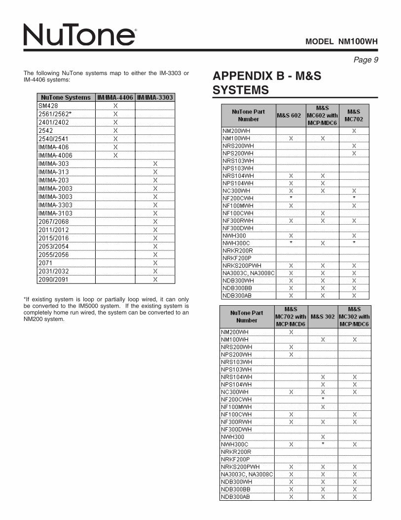
appeNdix b - m&s systems
*If existing system is loop or partially loop wired, it can onlybeconverted to the IM5000system. If theexistingsystem iscompletelyhomerunwired,thesystemcanbeconvertedtoanNM200system.
The following NuTone systems map to either the IM-3303 orIM-4406systems:

model Nm100WH
Page �0

model Nm100WH
Page ��
Two Year Limited WarrantyWARRANTY OWNER: Broan-NuTone warrants to the original consumer purchaser of its products that such products will be free from defects in materials or workmanship for a period of two (2) years from the date of original purchase. THERE ARE NO OTHER WARRANTIES, EXPRESS OR IMPLIED, INCLUDING, BUT NOT LIMITED TO, IMPLIED WARRANTIES OF MERCHANTABILITY OR FITNESS FOR A PARTICULAR PURPOSE. During this two year period, Broan-NuTone will, at its option, repair or replace, without charge, any product or part which is found to be defective under normal use and service. THIS WARRANTY DOES NOT EXTEND TO FLUORESCENT LAMP STARTERS OR TUBES, FILTERS, DUCT, ROOF CAPS, WALL CAPS AND OTHER ACCESSORIES FOR DUCTING. This warranty does not cover (a) normal maintenance and service or (b) any products or parts which have been subject to misuse, negligence, accident, improper maintenance or repair (other than by Broan-NuTone), faulty installation or installation contrary to recommended installation instructions.The duration of any implied warranty is limited to the two year period as specified for the express warranty. Some states do not allow limitation on how long an implied warranty lasts, so the above limitation may not apply to you.BROAN-NUTONE’S OBLIGATION TO REPAIR OR REPLACE, AT BROAN-NUTONE’S OPTION, SHALL BE THE PURCHASER’S SOLE AND EXCLUSIVE REMEDY UNDER THIS WARRANTY. BROAN-NUTONE SHALL NOT BE LIABLE FOR INCIDENTAL, CONSEQUENTIAL OR SPECIAL DAMAGES ARISING OUT OF OR IN CONNECTION WITH PRODUCT USE OR PERFORMANCE. Some states do not allow the exclusion or limitation of incidental or consequential damages, so the above limitation or exclusion may not apply to you. This war-ranty gives you specific legal rights, and you may also have other rights, which vary from state to state. This warranty supersedes all prior warranties.WARRANTY SERVICE: To qualify for warranty service, you must (a) notify Broan-NuTone at the address or telephone number below, (b) give the model number and part identi-fication and (c) describe the nature of any defect in the product or part. At the time of requesting warranty service, you must present evidence of the original purchase date. Date of Installation Builder or InstallerModel No. and Product Description
IF YOU NEED ASSISTANCE OR SERVICE - CONTACT:Broan-NuTone LLC Hartford, Wisconsin www.nutone.com 888-336-3948
Broan-NuTone Canada Mississauga, Ontario www.nutone.ca 877-896-1119 Rev. 08/2007
Garantie limitée de deux ansGARANTIE DU PROPRIÉTAIRE: Broan-NuTone garantie à l’acheteur original de ses produits que ces derniers seront exmpts de tout défaut de matériaux et de fabrication pour une période de deux (2) ans à compter de la date d’acha. AUCUNE AUTRE GARANTIE, IMPLICITE OU EXPRESSE, N’EST DONNÉE, Y COMPRIS, MAIS SANS S’Y LIMITER, GARANTIE DE MARCHANDIBILITÉ OU D’ADAPTATION À UN USAGE PARTICULIER.Pendant cette période de deux ans, Broan-NuTone procédera au remplacement ou à la réparation sans aucuns frais, mais à sa propre discrétion, de tout produit ou pièce jugé défectueux dans le cadre d’une utilisation normale. CETTE GARANATIE NE VISE PAS LES DISPOSITIFS D’AMORCAGE NI LES TUBES DES LUMINAIRES FLUORESCENTS. Cette garantie ne couvre pas (a) l’entretien et le service courants ni (b) les produits et les pièces ayant fait l’objet du’n usage abusif, de négligence, d’un accident, d’un entretien ou d’une réparation non appropriée (par du personnel non autorisé par Broan-NuTone) d’une mauvaise installation ou d’une installation non conforme aux directives d’installation fournies.La durée de toute garantie implicite est limitée à la période de deux ans précisée pour la garantie expresse. Certains états ne reconnaissent pas les restrictions relatives à la durée des garanties implicites; il se pourrait donc que cette restriction ne s’applique pas dans votre cas.LE REMPLACEMENT OU LA RÉPARATION PAR BROAN-NUTONE, À SA PROPRE DISCRÉTION, DE TOUT PRODUIT OU PIÈCE DÉFECTUEUX CONSTITUE LE SEUL REMÈDE DE L’ACHETEUR EN VERTU DE CETTE GARANTIE. BROAN-NUTONE NE PEUT ÊTRE TENUE RESPONSABLE DES DOMMAGES INDIRECTS, CONSÉCUTIFS OU SPÉCIAUX ATTRIBUABLES À UTILISATION OU AU RENDEMENT DU PRODUIT. Certains états ne reconnaissent pas les restrictions ni les exclusions relatives aux dommages indirects, consécutifs ou spéciaux; il se pourrait donc que cette restriction ne s’applique pas dans votre cas. La présente garantie vous accorde des droits spécifiques, mais vous pourriez aussi avoir d’autres droits en fonction de l’état dans lequel vous résidez. Cette garantie remplace toute autre garantie donnée précédement.SERVICE SOUS GRANTIE: Pour être admissible au service sous garantie, vous devez (a) aviser Broan-NuTone, à l’adresse ou au numéro de téléphone ci-dessous, (b) fournir le numéro du modèle et la description de la pièce et (c) décrire la nature défaut de la pièce ou du produit. Au moment de la demande de service sous garantie, vous devez fournir une preuve de la date d’achat originale.Date d’installationEntrepeneur ou installateurN° de modèle et description du produit
POUR OBTENIR DE L’ASSITANCE OU DU SERVICE - CONTACTEZ:Broan-NuTone LLC Hartford, Wisconsin www.nutone.com 888-336-3948
Broan-NuTone Canada Mississauga, Ontario www.nutone.ca 877-896-1119 Rev. 08/2007
Garantia limitada de dos añosGARANTÍA DEL PROPIETARIO: Broan-NuTone garantiza al comprador consumidor original de sus productos, por el período de dos (2) años desde la fecha original de compra, que tales productos están libres de defectos en material y mano de obra. NO HAY OTRAS GRANTÍAS, EXPRESADOS O SOBREENTENDIDAS, INCLUYENDO, PERO NO LIMITADAS A, GRANTÍAS NO EXPRESADAS DE MERCHNTIBILIDAD O ADAPTABLES A UN PROPÓSITO EN PARTICULAR. Durante este período de dos años, Broan-NuTone reparará o reemplazará a su opción y sin costo, cualquier producto o parte que se encuentre defectuoso bajo condiciones normales de uso y servicio. ESTA GARANTÍA NO CUBRE A LOS ARRANCADORES PARA LÁMPARAS FLUORESCENTES O A LOS TUBOS FLUORESCENTES, FILTROS, DUCTOS, TAPAS DE TECHO, TAPAS DE PARED Y OTROS ACCESORIOS PARA CANALIZACIÓN. Esta granatía no cubre (a) Mantenimiento y servicios normales (b) Productos o partes sujetos al mal uso, negligencia, accidente, mantenimiento inadecuado o reparaciones (port otros ajenos a Broan-NuTone), instalación defectusoa o a una instalación contraria a las instrucciones de instalación recomendadas.La duración de cualquier garantia no expresada está limitada a un periodo de dos años según se especifica en la garantia expresada. Algunos estados no permiten limitación en cuanto a la duración de una grantia no expresada, por lo que la limitación arriba indicada puede que no se apliqué a Ud.LA OBLIGACIÓN DE BROAN-NUTONE DE REPARAR O REEMPLAZAR A SU OPCIÓN, SERÁ EL ÚNICO Y EXCLUSIVO RECURSO QUE TENDRÁ EL COMPRADOR BAJO ESTA GARANTÍA. BROAN-NUTONE NO SERÁ RESPONSABLE POR DAÑOS INCIDENTALES, CONSECUENTES O ESPECIALES QUE RESULTEN A CONSECUENCIA O SEAN INDEPENDIENTE DEL USO O DESEMPEÑO DEL PRODUCTO. Algunos estados no permiten la exclusión o limitación de daños incidentals o consecuentes, de modo que la limitación o exclusión arriba indicada pueda que no se aplique a Ud. Esta garantia le proporciona derechos legales especificos, y Ud.puede tener otros derechos, los cuales varían de estado a estado. Esta garantias reemplaza a todas las garantías anteriores..SERVICO DE GARANTÍA: Para tener derecho al servicio de garantía, Ud. debe (a) Notificar a Broan-NuTone a la dirección o el número de teléfono abajo, (b) indicar el número de modelo y la identifación de la party y (c) describir la naturaleza de cualquier defecto en la producto o parte. Al momento de solicitor el servicio por la garantía, Ud. debe presentar la evidencia de la fecha original de compra.Fecha de la instalaciónConstructor o instaladorNúmero de modelo y descripción del producto
SI NECESITA ASISTENCIA O SERIVIVIO - CONTACTO:Broan-NuTone LLC Hartford, Wisconsin www.nutone.com 888-336-3948
Broan-NuTone Canada Mississauga, Ontario www.nutone.ca 877-896-1119 Rev. 08/2007