nnp1-ms-md-006-a1 - namngiep1.com obayashi corporation ... 5.1 survey work 16 ... 5.2.4 installation...
TRANSCRIPT


NAM NGIEP 1 HYDROPOWER PROJECT DWP and SS-ESMMP for Construction of River Diversion Structure Works at Inlet and Outlet
NNP1-MS-MD-006-A1
OBAYASHI CORPORATION Page 1 Revision: A1 November 2014
CONTENT
Page
REVISION STATUS 3
PART 1 : DETAILED WORKS PROGRAME
1 GENERAL 5
1.1 Outlet Portal of Tunnel Structure Works 5
1.2 Inlet Portal of Tunnel Structure Works 8
2 REFERENCE 11
3 MATERIALS 12
4 EQUIPMENT AND MANPOWER 12
4.1 Equipment and Tool 12
4.2 Nominated Subcontractor and Manpower Distribution 13
4.3 Temporary Facilities 14
5 CONSTRUCTION PROCEDURE 15
5.1 Survey Work 16
5.2 Structure Works for Inlet and Outlet of Diversion Tunnel 16
5.2.1 Leveling Surface and Compaction 16
5.2.2 Leveling Concrete 16
5.2.3 Rebar and Formwork Fabrication 16
5.2.4 Installation Rebar and Formwork for Bottom Slab 17
5.2.5 Casting concrete for Bottom Slab 18
5.2.6 Installation Rebar and Formwork for Wall 18
5.2.7 Casting concrete for Wall 20
5.2.8 Installation Rebar and Formwork for Top Slab 20
5.2.9 Casting Concrete for Top Slab 20
5.2.10 Drainage 20
6 SAFETY CONTROL 21
7 QUALITY ASSURANCE 22

NAM NGIEP 1 HYDROPOWER PROJECT DWP and SS-ESMMP for Construction of River Diversion Structure Works at Inlet and Outlet
NNP1-MS-MD-006-A1
OBAYASHI CORPORATION Page 2 Revision: A1 November 2014
PART 2 : SITE SPECIFIC ENVIRONMENT & SOCIAL MANAGEMENT & MONITORING PLAN ( SS – ESMMP)
8 ENVIRONMENTAL& SOCIAL MANAGEMENT& MONITORING PLAN 24
8.1 Introduction 24
8.2 Environmental and Social Pre-Construction Description 24
8.2.1 Land Use 24
8.2.2 Significant Biological Features 25
8.2.3 Proximity to Villages, Cultural Sites 25
8.3 Sub-Plan Detail for Inlet& Outlet Structure – Environment 29
8.4 Sub-Plan Detail for Inlet& Outlet Structure – Social 31
8.5 Chance Find Procedures 33
9 APPENDIX 34
9.1 Organization of Diversion Tunnel Inlet & Outlet
9.2 Construction Schedule of Diversion Tunnel Inlet & Outlet
9.3 Emergency Action Plan
9.4 Working Drawings for Inlet & Outlet Structure Works
9.5 Resources for Inlet & Outlet for Structure Works
9.6 Temporary Facility Layout for River Diversion Tunnel Inlet & Outlet
9.7 Construction Sequence of Inlet & Outlet Structure Works
9.8 Inspection and Test Plans (ITP)
9.9 Sub-plans for ESMMP-CP
9.10 Environmental Management Activity Table

NAM NGIEP 1 HYDROPOWER PROJECT DWP and SS-ESMMP for Construction of River Diversion Structure Works at Inlet and Outlet
NNP1-MS-MD-006-A1
OBAYASHI CORPORATION Page 3 Revision: A1 November 2014
REVISION STATUS
Rev. No. Description Issue Date Remarks
A1
1st Submission for Owner Review
12/November/2014
NAM NGIEP 1 HYDROPOWER PROJECT DWP and SS-ESMMP for Construction of River Diversion Structure Works at Inlet and Outlet
NNP1-MS-MD-006-A1
OBAYASHI CORPORATION Page 4 Revision: A1 November 2014
PART 1
DETAILED WORKS PROGRAME
(DWP)
NAM NGIEP 1 HYDROPOWER PROJECT DWP and SS-ESMMP for Construction of River Diversion Structure Works at Inlet and Outlet
NNP1-MS-MD-006-A1
OBAYASHI CORPORATION Page 5 Revision: A1 November 2014
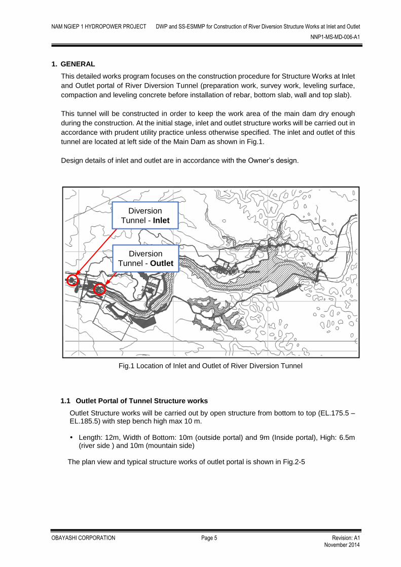
1. GENERAL
This detailed works program focuses on the construction procedure for Structure Works at Inlet
and Outlet portal of River Diversion Tunnel (preparation work, survey work, leveling surface,
compaction and leveling concrete before installation of rebar, bottom slab, wall and top slab).
This tunnel will be constructed in order to keep the work area of the main dam dry enough
during the construction. At the initial stage, inlet and outlet structure works will be carried out in
accordance with prudent utility practice unless otherwise specified. The inlet and outlet of this
tunnel are located at left side of the Main Dam as shown in Fig.1.
Design details of inlet and outlet are in accordance with the Owner’s design.
Fig.1 Location of Inlet and Outlet of River Diversion Tunnel
1.1 Outlet Portal of Tunnel Structure works
Outlet Structure works will be carried out by open structure from bottom to top (EL.175.5 – EL.185.5) with step bench high max 10 m.
Length: 12m, Width of Bottom: 10m (outside portal) and 9m (Inside portal), High: 6.5m
(river side ) and 10m (mountain side)
The plan view and typical structure works of outlet portal is shown in Fig.2-5
Diversion
Tunnel - Outlet
Diversion
Tunnel - Inlet

NAM NGIEP 1 HYDROPOWER PROJECT DWP and SS-ESMMP for Construction of River Diversion Structure Works at Inlet and Outlet
NNP1-MS-MD-006-A1
OBAYASHI CORPORATION Page 6 Revision: A1 November 2014
Fig.2 Plan view of Diversion Tunnel Outlet
Fig.3 Typical Bar Arrangement Drawing of Diversion Tunnel Outlet

NAM NGIEP 1 HYDROPOWER PROJECT DWP and SS-ESMMP for Construction of River Diversion Structure Works at Inlet and Outlet
NNP1-MS-MD-006-A1
OBAYASHI CORPORATION Page 7 Revision: A1 November 2014
Fig.4 Typical cross section at Diversion Tunnel Outlet Structure
Fig.5 Typical longitudinal section at Diversion Tunnel Outlet Structure

NAM NGIEP 1 HYDROPOWER PROJECT DWP and SS-ESMMP for Construction of River Diversion Structure Works at Inlet and Outlet
NNP1-MS-MD-006-A1
OBAYASHI CORPORATION Page 8 Revision: A1 November 2014
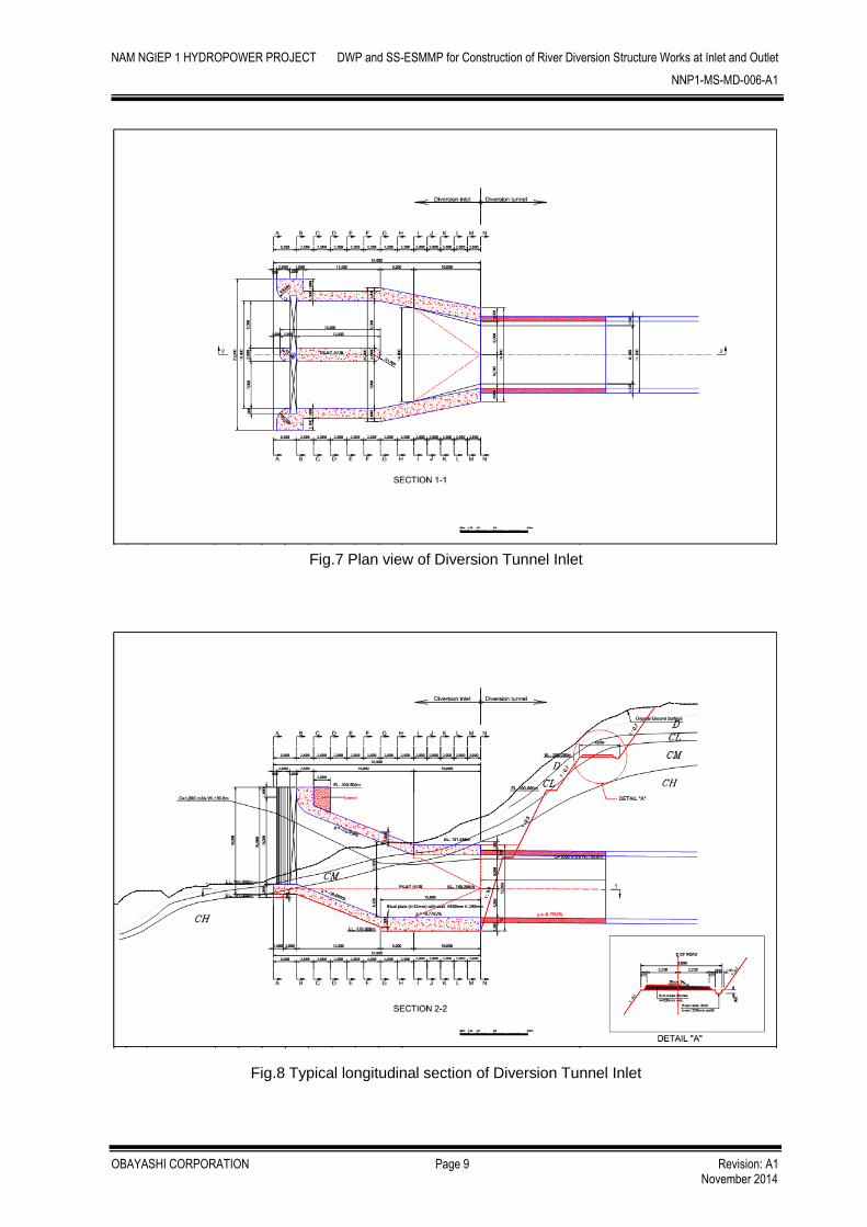
1.2 Inlet Portal of Tunnel for Structure works
Inlet Structure works will be carried out by open structure from bottom to top slab (EL.179.0 ~ EL.200.5) with step bench high max 10 m.
Length: 31m, Width: 22.6m (outside portal) and 14m (inside portal), High: 16.5m Inlet Axis is at the center of Inlet portal, Length:15m, Width: 2m and High:16.5m
The plan view and typical cross section of Inlet portal is shown in Fig.6-9
Fig.6 Detail plan view of Diversion Tunnel Inlet
NAM NGIEP 1 HYDROPOWER PROJECT DWP and SS-ESMMP for Construction of River Diversion Structure Works at Inlet and Outlet
NNP1-MS-MD-006-A1
OBAYASHI CORPORATION Page 9 Revision: A1 November 2014
Fig.7 Plan view of Diversion Tunnel Inlet
Fig.8 Typical longitudinal section of Diversion Tunnel Inlet

NAM NGIEP 1 HYDROPOWER PROJECT DWP and SS-ESMMP for Construction of River Diversion Structure Works at Inlet and Outlet
NNP1-MS-MD-006-A1
OBAYASHI CORPORATION Page 10 Revision: A1 November 2014
Fig.9 Typical cross section at Diversion Tunnel Inlet

NAM NGIEP 1 HYDROPOWER PROJECT DWP and SS-ESMMP for Construction of River Diversion Structure Works at Inlet and Outlet
NNP1-MS-MD-006-A1
OBAYASHI CORPORATION Page 11 Revision: A1 November 2014
The major quantities for Inlet and Outlet structure works at River Diversion Tunnel are shown in Table 1. These quantities should be conferred with the Owner separately because of change of the existing ground and geology condition.
Table 1. Major Quantities for Inlet and Outlet Structure works at River Diversion Tunnel
No. Description Quantity Unit Remark
Outlet
1 Lean Concrete 0.1m thick 14 MPa 12 m3
2 Concrete Bottom Slab 0.5m thick 21 MPa 62 m3
3 Concrete Wall 0.5m thick 21 MPa 104 m3
4 Rebar SD40 5 Tons (ф12)
Inlet
1 Lean Concrete 0.1 m thick 14 MPa 66 m3
2 Concrete Bottom Slab 1.5m & 2.0m thick 24 MPa 1,023 m3
3 Concrete Wall 1.5m & 2.0m thick 24 MPa 1,607 m3
4 Concrete Top Slab 1.5m thick 24 MPa 834 m3
5 Rebar SD40 354 Tons (ф16,20,25)
Note) the above quantities are estimation based on the design drawing and might be
changed subject to actual geological condition.
In environmental view, the key features of Structure works at Inlet and Outlet of River Diversion
Tunnel are summarized as below.
The construction area of Inlet and Outlet are located at the left bank side and there are
no village around there. Therefore the influence on neighborhood inhabitants by this
construction is very small.
The land along Inlet and Outlet is almost government land before commencement of this
construction.
There is no creek and small river with water flow in the dry season at Inlet and Outlet area.
2. REFERENCE
Referenced Specifications:
- River Diversion : GR 2.3.1, TS 1.2
- Earthwork : TS 2.2, 2.3, 8.2
- Drainage : TS 9.3
- Revetment : TS 3.3, 3.4, 3.5, 3.9
- Concrete : TS 6

NAM NGIEP 1 HYDROPOWER PROJECT DWP and SS-ESMMP for Construction of River Diversion Structure Works at Inlet and Outlet
NNP1-MS-MD-006-A1
OBAYASHI CORPORATION Page 12 Revision: A1 November 2014
3. MATERIAL Table 2. Material to be used
No. Description Class / Type Use for
1 Concrete for Inlet & Outlet 21 MPa &24 MPa Concrete Structure of Inlet and Outlet Portal 2 Rebar SD40
4. EQUIPMENT AND MANPOWER
4.1 Equipment and Tool
Table 3. Major Equipment List
No. Equipment / Tool Capacity Nos Purpose
1 Excavator 0.7 m3 1 Excavation, Loading
2 Bulldozer 21 ton 1 Spreading Material
3 Compactor Roller 10 ton 1 Compaction Soil
4 Motor Grader 12 ton 1 Spreading Material
5 Mobile Concrete Pump Truck 30 m3/h 2 Concrete Placing
6 Concrete Mixer Truck 5 m3 5 Transportation Concrete
7 Mobile Crane Truck 25 ton,35 ton 2 Erection Formwork, Rebar
8 Unit Truck with Crane 5 ton 1 Material Transportation etc.
9 Service Truck 2-4 tons 2 Material Transportation etc.
10 Air Compressor 375 cfm 1 Cleaning Surface
11 Generator 600 kVA 1 Supply Electric Power
12 Concrete Vibrator 4 To Compact Concrete
13 Submersible Pump 2” - 6” 4 Cleaning, Dewatering
14 Welding Machine 4 Assembly Formworks
15 Cutter machine 2 Cutting Rebar
16 Bar Bender machine 1 Bending Rebar
17 Scaffolding 500 kg 1,200 Supporting Formwork
Resource schedule for Inlet and Outlet is shown in Appendix 9.5

NAM NGIEP 1 HYDROPOWER PROJECT DWP and SS-ESMMP for Construction of River Diversion Structure Works at Inlet and Outlet
NNP1-MS-MD-006-A1
OBAYASHI CORPORATION Page 13 Revision: A1 November 2014
4.2 Nominated Subcontractor and Manpower distribution
Nominated Subcontractor: RIGHT TUNNELLING CO., LTD. In general, the subcontractor will be nominated, concerning not only price/rate but also following items, fully described below.
1) Technical competence
2) Financially stable
3) Administrative competence
4) Past project experience and reference
5) Ability to meet schedule
6) Quality and skill of work
7) Capacity(equipment, staff, worker) and organization
8) Ability to meet safety and environment requirements.
And then, the evaluation for subcontractor will be done and recorded.
Manpower distribution for this work is planned as below.
Table 4. Manpower Distribution for Inlet and Outlet excavation works
No. Manpower Planned
Number Duty
1 Engineer 1 Site management
2 Engineer 2 Site engineering
3 Foreman 6 Work management
4 Equipment operator 5 Excavator, Roller, Bulldozer
5 Driver 11 Pump car, Crane Truck, Unit Truck…
6 Skill Workers 12 Rebar works, Form works, Concreting
7 Common worker 48 Assistant to skilled worker
8 Security guard 4 Security Site Materials
9 Mechanic 1 Maintenance of equipment
10 Electrician 1 Electrical equipment maintenance
11 Chief Surveyor 1 Survey chief
12 Assistant Surveyor 4 Survey assistant
Total 96

NAM NGIEP 1 HYDROPOWER PROJECT DWP and SS-ESMMP for Construction of River Diversion Structure Works at Inlet and Outlet
NNP1-MS-MD-006-A1
OBAYASHI CORPORATION Page 14 Revision: A1 November 2014
4.3 Temporary Facilities
Table 5.Major Temporary Facilities
No. Facilities Location
1 Contractor’s Camp STA.4+900 (P1)
2 Worker’s Camp No.2
(Sub Contractor’s Office) STA.6+120 (P1)
3 Temporary Facility of River Diversion Inlet
4 Disposal Area (No.2) Left Bank
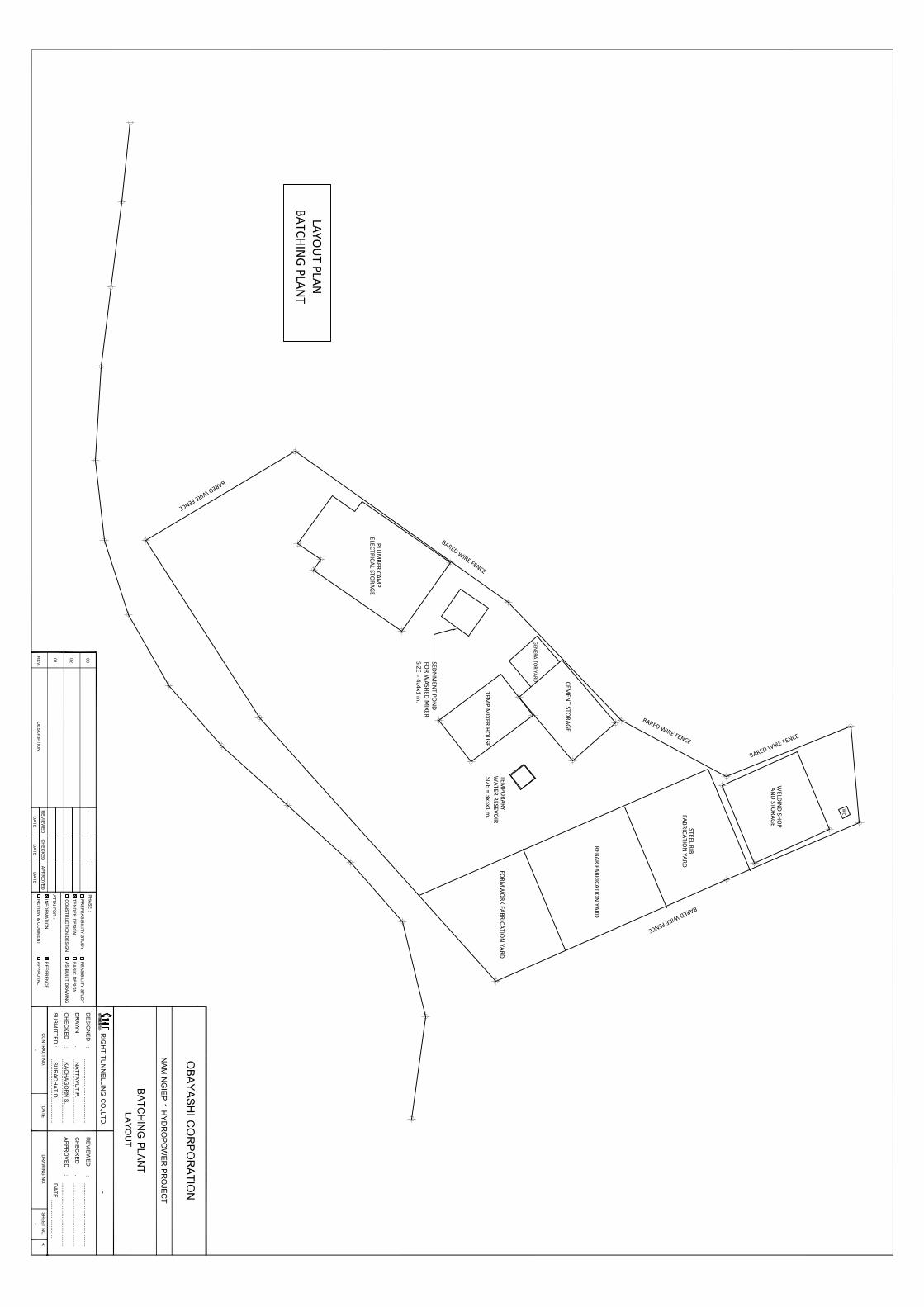
The layout plan of Temporary Facility for River Diversion Structure is shown in Appendix 9.6
Fig.10 Major Temporary Facilities Map
Disposal Area No.2
Worker’s Camp No.2
Contractor’s Camp
Inlet
Outlet

NAM NGIEP 1 HYDROPOWER PROJECT DWP and SS-ESMMP for Construction of River Diversion Structure Works at Inlet and Outlet
NNP1-MS-MD-006-A1
OBAYASHI CORPORATION Page 15 Revision: A1 November 2014
5. CONSTRUCTION PROCEDURES
Typical construction procedure for Inlet and Outlet Structure works at River Diversion Tunnel is
shown in Fig. 11. The detail of construction sequence is shown in Appendix 9.7
Fig.11 Construction Procedure for Inlet and Outlet Structure works

NAM NGIEP 1 HYDROPOWER PROJECT DWP and SS-ESMMP for Construction of River Diversion Structure Works at Inlet and Outlet
NNP1-MS-MD-006-A1
OBAYASHI CORPORATION Page 16 Revision: A1 November 2014
5.1 Survey Work
Firstly temporary benchmarks for elevation and coordinate are established around
work area. Refer to section no. 5.1 in the Detailed Work Program for Inlet and Outlet
River Diversion Excavation Works, NNP1-MS-MD-001.
After inspection by the Owner on the leveling and compaction works will be started.
The position of installation rebar so be marked by survey.
Survey instruments shall be calibrated in accordance with the section 5.3.3 testing
equipment and facilities of the latest Quality Assurance Program (Document No.
NNP1-PRG-DrQAP-A3) enclosed with Contractor letter NNP1-PCL-00086, dated 16th
January 2014.
5.2 Structure Works for Inlet and Outlet of Diversion Tunnel
5.2.1 Surface Clearing
Before structure works, the surface should be cleaned and leveled. Clearing shall
consist of the removal and disposal of everything above surface level, that include
broken stone, trees, stumps, logs, bush, undergrowth, grass, crops and loose
vegetable matter.
5.2.2 Leveling Concrete
After cleaning, the leveling concrete that is class 14Mpa shall be provided to level the
surface.
Excavator using for pouring concrete shall be set up on the working platform. Concrete
shall be transported to site by mixer truck then discharge to the Hoe of Excavator.
Concrete shall be put on blinding stone and/or wreckage of rock by excavator and
levelling by manpower. After placing concrete, surface shall be finished by using a
trowel. In some cases, the Excavator can’t set up on the working platform, the concrete
pump shall be used to pour concrete.
5.2.3 Rebar and Formwork Fabrication
Fabrication Yard:
Rebar workshops and rebar storage yard will be established at temporary batching
plant area at disposal area no.2 (Appendix 9.6)
All reinforcement shall be stock piled by its own kind and keep elevated from the
ground with proper covering to insure that the rebar shall be free from any means of
getting wet to avoid rust.
Rebar Fabrication:
Rebar shall be fabricated as approved working drawing at rebar workshops with the
use of bending and cutting machines. After completion of fabrication for each piece, it
shall be carefully kept in the dry and stable condition at stockyard, which is more 20cm
higher than ground surface and no water flooded areas and covered by plastic sheet
to protect rain weather.
NAM NGIEP 1 HYDROPOWER PROJECT DWP and SS-ESMMP for Construction of River Diversion Structure Works at Inlet and Outlet
NNP1-MS-MD-006-A1
OBAYASHI CORPORATION Page 17 Revision: A1 November 2014
The rebar should be deformed bar with diameter of 12, 16, 20 and 25mm as shown in
working drawing. The JIS G3112-1987 standard is its Specification of SD40 grade as
Yield Point from 390Mpa to 510Mpa and Tensile Strength in 560Mpa Min.
Formwork Fabrication:
Formwork shall be fabricated at fabrication yard and conformed to designed drawing.
At some irregular position such as corner, rubber form shall be used to fill-in the gap
between two panel forms. All forms shall be cleaned free from dust, grease or other
matter and shall be applied form-oil before installation. And before casting concrete,
surface of formwork shall be cleaned again by water to prevent dust from surface of
concrete after casting. In order to run off water outside formwork, bottom formwork will
be arranged a cleaning window.
5.2.4 Installation of Rebar and Formwork for Bottom Slab
Inlet
Inlet bottom slab shall be divided into 3 blocks. Sequencing of areas where
construction would be started from the lower to higher portion (Appendix 9.7).
Layout of rebar skeleton shall be marked clearly at the surface of the lean concrete.
Rebar should be set up to reach exact position considering the appropriate concrete
covering.
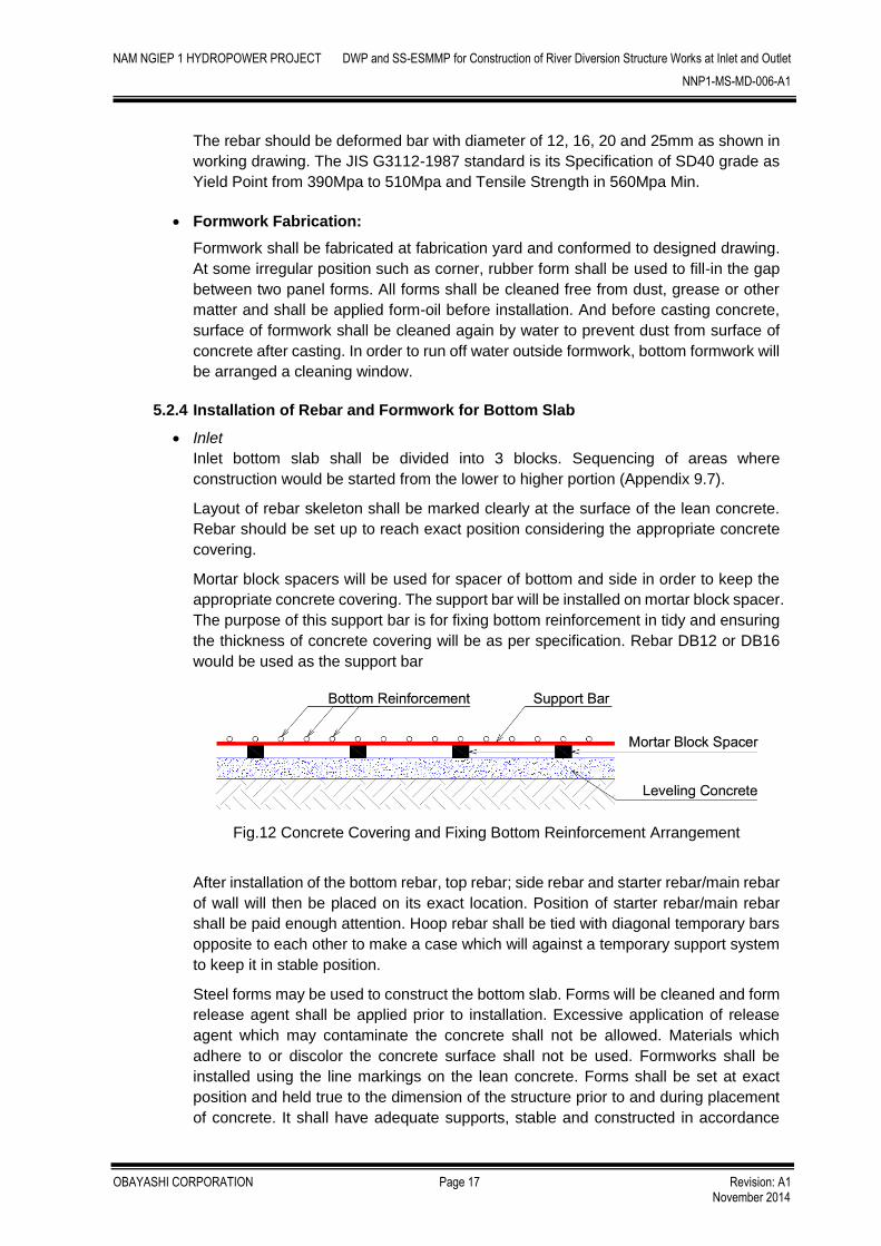
Mortar block spacers will be used for spacer of bottom and side in order to keep the
appropriate concrete covering. The support bar will be installed on mortar block spacer.
The purpose of this support bar is for fixing bottom reinforcement in tidy and ensuring
the thickness of concrete covering will be as per specification. Rebar DB12 or DB16
would be used as the support bar
Fig.12 Concrete Covering and Fixing Bottom Reinforcement Arrangement
After installation of the bottom rebar, top rebar; side rebar and starter rebar/main rebar
of wall will then be placed on its exact location. Position of starter rebar/main rebar
shall be paid enough attention. Hoop rebar shall be tied with diagonal temporary bars
opposite to each other to make a case which will against a temporary support system
to keep it in stable position.
Steel forms may be used to construct the bottom slab. Forms will be cleaned and form
release agent shall be applied prior to installation. Excessive application of release
agent which may contaminate the concrete shall not be allowed. Materials which
adhere to or discolor the concrete surface shall not be used. Formworks shall be
installed using the line markings on the lean concrete. Forms shall be set at exact
position and held true to the dimension of the structure prior to and during placement
of concrete. It shall have adequate supports, stable and constructed in accordance

NAM NGIEP 1 HYDROPOWER PROJECT DWP and SS-ESMMP for Construction of River Diversion Structure Works at Inlet and Outlet
NNP1-MS-MD-006-A1
OBAYASHI CORPORATION Page 18 Revision: A1 November 2014
with the construction drawings. Access openings may be provided for cleaning out
extraneous materials immediately before concrete placement.
Dimensions, alignment and elevation of top concrete shall be checked and must be
within the allowable tolerance described in inspection and test plan at quality control
item.
Metal ties or anchorages within the form shall be so constructed as to install and
remove the formwork without causing damage. Forms shall not be removed until the
concrete has attained sufficient strength to prevent damage to the concrete surface
preferably after 24 hours. Prior to re-use, forms shall be inspected for damaged and if
so must be repaired.
Outlet
Outlet bottom slab shall be constructed as a unity. Rebar and formwork will be installed
as per description in Inlet.
5.2.5 Casting Concrete for Bottom Slab
Before concreting, it should be carried out installation of the embedded material, the
temporary item for casting concrete such as the spacer, the concrete pump pipe
system if use pump truck. The formwork surface should be cleaned before concreting
by high pressure water.
After inspection of the Owner, the concreting can be commenced. Concrete will be
supplied by CVC plant.
Concrete shall be poured by the concrete pump (boom length type) or truck mixer.
Each concrete layer after pouring, vibrator will be used to consolidate the concrete.
When vibrating later concrete layer, the vibrator head shall penetrate at least 15 cm.
depth into previous layer.
Concrete surface level will be made by leveling instrument and finished by wooden
trowel.
Concrete for bottom slab at Inlet is class C24 and Outlet is class C21.
The concreting should be in the early of morning. In the raining case, placed concrete
will be cover by canvas, water shall flow from higher to lower position and not join into
concrete.
The concreting must be recorded the necessary information (temperature, slump,
quantity…) and report to the Owner.
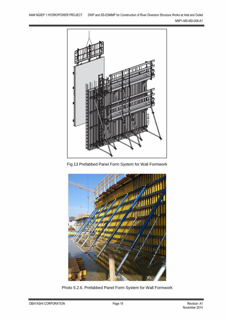
5.2.6 Installation of Scaffolding, Rebar and Formwork for Wall
This item shall be constructed same to method that is described in 5.2.4 – Installation
of rebar and formwork for bottom slab.
The detailed drawing and structural calculation of wall formwork will be proposed to
Owner separately prior to commencement of work.
NAM NGIEP 1 HYDROPOWER PROJECT DWP and SS-ESMMP for Construction of River Diversion Structure Works at Inlet and Outlet
NNP1-MS-MD-006-A1
OBAYASHI CORPORATION Page 19 Revision: A1 November 2014
Fig.13 Prefabbed Panel Form System for Wall Formwork
Photo 5.2.6. Prefabbed Panel Form System for Wall Formwork
NAM NGIEP 1 HYDROPOWER PROJECT DWP and SS-ESMMP for Construction of River Diversion Structure Works at Inlet and Outlet
NNP1-MS-MD-006-A1
OBAYASHI CORPORATION Page 20 Revision: A1 November 2014
5.2.7 Casting Concrete for Wall
This item shall be constructed same to method that is described in 5.2.5 – Casting
concrete for bottom slab.
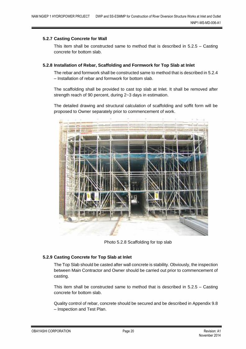
5.2.8 Installation of Rebar, Scaffolding and Formwork for Top Slab at Inlet
The rebar and formwork shall be constructed same to method that is described in 5.2.4
– Installation of rebar and formwork for bottom slab.
The scaffolding shall be provided to cast top slab at Inlet. It shall be removed after
strength reach of 90 percent, during 2~3 days in estimation.
The detailed drawing and structural calculation of scaffolding and soffit form will be
proposed to Owner separately prior to commencement of work.
Photo 5.2.8 Scaffolding for top slab
5.2.9 Casting Concrete for Top Slab at Inlet
The Top Slab should be casted after wall concrete is stability. Obviously, the inspection
between Main Contractor and Owner should be carried out prior to commencement of
casting.
This item shall be constructed same to method that is described in 5.2.5 – Casting
concrete for bottom slab.
Quality control of rebar, concrete should be secured and be described in Appendix 9.8
– Inspection and Test Plan.

NAM NGIEP 1 HYDROPOWER PROJECT DWP and SS-ESMMP for Construction of River Diversion Structure Works at Inlet and Outlet
NNP1-MS-MD-006-A1
OBAYASHI CORPORATION Page 21 Revision: A1 November 2014
5.2.10 Drainage
Structure works at Inlet and Outlet portal of River Diversion Tunnel will be carried out
in dry season according to the construction schedule (Appendix 9.2), and additionally
considering the following conditions, sedimentation pond and open ditch will not be
installed for these works.
- At Inlet portal, the level of subgrade at riverside is higher than the river water
level that will allow dry condition works.
- At Outlet portal, temporary flood protection dike will be constructed that will
allow dry condition works.
- At Inlet and Outlet portal, there is no inflow of mountain runoff.
In case of turbid water flowing, temporary sedimentation pond with submersible pump
shall be installed to protect and prevent turbid water from flowing out of the
construction area.
The location of temporary sedimentation pond will be changed according to the
structure situation. Prepared submersible pumps will be 2” ~ 6” size. These pumps
will be used according to the turbid water flowing.
6. SAFETY CONTROL
Safety control for site works shall be followed to the latest Safety and Security Program
(Document No. NNP1-PRG-SSP-A3) enclosed with Contractor’s letter NNP1-PCL-00044,
dated 10th December 2013.
Daily working cycle on this site is shown in below.
Fig. 21 Daily Working Cycle
Pre-working MeetingWorking and Safety Schedule for Today
Pre-working CheckSite and Facilities Condition
Working
Clearing after WorkingSite and Facilities
Daily MeetingWorking and Safety Schedule for Tomorrow
AM
PMWorking
NAM NGIEP 1 HYDROPOWER PROJECT DWP and SS-ESMMP for Construction of River Diversion Structure Works at Inlet and Outlet
NNP1-MS-MD-006-A1
OBAYASHI CORPORATION Page 22 Revision: A1 November 2014
Especially for Inlet and Outlet Structure works area, the following issues shall be concerned.
1) Striking heavy equipment and crane accident
For all staffs and worker, the safety training shall be carried out.
Warning sign boards will be arranged.
Don’t approach the working radius of heavy equipment.
In case that the worker needs to approach the equipment, he shall request the
operator to stop operation and confirm the stopping.
Watch man shall be arranged.
Never enter under lifting work.
2) Falling from high place
Use safety belt on high place (H >2m).
Daily check for Scaffold shall be done.
Before commencement work, safety training will be carried out to relevant staffs and workers.
And the emergency action plan is attached in Appendix 9.3
7. QUALITY ASSURANCE
Quality Assurance shall be followed to the Quality Assurance Program (Document No. NNP1-
PRG-DrQAP-A3) in the NNP1-PCL-00086, dated 16th January 2014.
Material testing during construction will be performed by on-site laboratory as specified in
specifications. And the proposed Inspection and Test Plans (ITP) are as shown in the Appendix
9.8
The dimensions of As-built will be measured and As-built drawings will be developed for
submission to the Owner.
The inspection and test on site shall be informed of the Owner before the implementation.
NAM NGIEP 1 HYDROPOWER PROJECT DWP and SS-ESMMP for Construction of River Diversion Structure Works at Inlet and Outlet
NNP1-MS-MD-006-A1
OBAYASHI CORPORATION Page 23 Revision: A1 November 2014
PART 2
SITE SPECIFIC ENVIROMENTAL AND SOCIAL
MANAGEMENT AND MONITORING PLAN
(SS-ESMMP)

NAM NGIEP 1 HYDROPOWER PROJECT DWP and SS-ESMMP for Construction of River Diversion Structure Works at Inlet and Outlet
NNP1-MS-MD-006-A1
OBAYASHI CORPORATION Page 24 Revision: A1 November 2014
8. ENVIRONMENTAL& SOCIAL MANAGEMENT& MONITORING
8.1 Introduction
This Site Specific Plan has been prepared to highlight environmental and social conditions
prior to the beginning of each construction activity and will be used as a tool to ensure the
particular activity follows the correct management and mitigation procedures. Sub-Plans will
be used to detail mitigation methods for each of the activities associated with the construction
or excavation works.
This plan details foundation and structural works for inlet and outlet portals of the river
diversion tunnel. The diversion tunnel will be used to divert water away from the main dam
area and allow dry conditions for construction works. The inlet and outlet are located on the
left side of the main dam. Main structure works will consist of using rock bolts, steel re-
enforcements and shotcrete, with the same technique used for upper slope stabilization.
Table 8.1 below shows the referential linkages of documents regarding environmental
matters in the NNP1 Project. The Owners (NNP1) documents use references and
information from the Concession Agreement. This SS ESMMP (Contractor) uses references
and information from Owners EIA/ESMMP and Owners ESMMP-CP.
Table 8.1 List of Main Documents and Approving Authority
Item Hierarchy of Documents Approving Authority
1 Concession Agreement GOL
2 NNP1 EIA/EMMP GOL
3 ESMMP-CP GOL
4 Contractors EMP NNP1
5 SS ESMMP NNP1
The Contractor documents are; Contractors EMP (Item 4) and SS ESMMP (Item5) which
have used applicable information extracted from the Owners documents which are
Concession Agreement (Item 1), NNP1 EIA/EMMP (Item 2) and ESMMP-CP (Item 3).
All obligations of the contractor are stated in the Civil Works Contract (CWC) which includes
Schedule 9 (Concession Agreement Pass Through Obligations) and is the only governing
document for the Contractor.
8.2 Environmental and Social Pre-Construction Description
8.2.1 Land Use
No permanent land use directly occurs in the construction area, with the terrain too
steep and rocky for any kind of agricultural development.
The construction area is along the left bank of Nam Ngiep River, which is within a deep
valley. The width of the river spans approximately 70m during the rainy season and
30m during the dry season. Water flow can be very fast during the wet season,
appropriate safety measures need to be taken when working within this area, and
these will be detailed further in the Sub-Plans.

NAM NGIEP 1 HYDROPOWER PROJECT DWP and SS-ESMMP for Construction of River Diversion Structure Works at Inlet and Outlet
NNP1-MS-MD-006-A1
OBAYASHI CORPORATION Page 25 Revision: A1 November 2014
8.2.2 Significant Biological Features
A targeted primate survey was undertaken in November 2013 and mentions two
species (by vocalization) of gibbons present in the project area, however their habitats
are located uphill areas outside of the inundation and Inlet/Outlet zone.
8.2.3 Proximity to Villages, Cultural Sites
The closest Village is Ban Hatsaykham, over 4km to the east of inlet/outlet construction
sites. There will be no direct impact to villages from construction activities apart from
potential traffic and dust hazards from machinery and trucks passing through
residential areas. There will be no impacts expected to temples or cemeteries.
Table 8.2 below is a pre-construction checklist to identify any major environmental
impacts that may occur during construction works. After completion of the checklist the
sub-plans can be selected accordingly.
Table 8.2 Environmental Assessment Checklist – For Pre Construction
Site Location Inlet (T4 STA.0+200) and Outlet (P2 STA.1+540)
GPS Coordination Inlet: E 344138.89, N 2062403.42 Outlet: E 344741.98, N 2062261.40
Photo See attached
Date 4th October 2014
Estimated Area 9,286m2
Prepared By Santi Sayakoummane
Checked By Keiji Sasaki
Site Description Inlet and Outlet structural works including slope stabilization and construction of temporary facilities.
Project Setting Yes No Description
Will the site require UXO clearance? X UXO clearance for the inlet and outlet construction sites has been conducted by NNP1
Is there surface water located in close proximity to the site?
X The site sits directly on the left bank for the Nam Ngiep
Is there a village or community located in close proximity to the site?
X Closest village is Ban Hatsaykham, approx. 4km east of site
Is the site located in a vegetated area?
X Vegetation has been previously cleared during earthworks stage
Is the site located in agricultural land? X Site is directly on the Nam Ngiep
Are there any Physical Cultural Resources (PCR) sites in the area?
X No confirmed PCR on site
Is there an existing access road to the site?
X The inlet portal is located at access road T4 STA.0+200 the outlet is location along P2 STA.1+540
Can the site be viewed from public viewpoints?
X From Nam Ngiep

NAM NGIEP 1 HYDROPOWER PROJECT DWP and SS-ESMMP for Construction of River Diversion Structure Works at Inlet and Outlet
NNP1-MS-MD-006-A1
OBAYASHI CORPORATION Page 26 Revision: A1 November 2014
Is the site located within an existing Construction Area?
X Alongside newly constructed access roads, T4 and T13
Will the site development require the construction of a sub-camp, office and storage? (if yes, provide a list)
X Worker Camp No.2 will be used for the Sub-Contractors worker camp. Location shown in Section 4.3, Figure.10 Part 1 of the DWP
Other Comments: Slope stabilization will take place to ensure
Environmental Impacts Likelihood (Yes/No)
Mitigation measure to be Implemented
Will the site development result in increased dust generation at near-by villages?
No No villages within vicinity of site
Will the site development result in increased noise generation at near-by villages?
No No villages within vicinity of site
Will the site development result in surface water turbidity?
Yes
The working level of the inlet will be above the water level. At the outlet a flood protection dike will be constructed to reduce sediment and water entering the construction site.
Will site development result in changes to drainage patterns?
Yes
All excavation/construction works will be conducted during the dry season and above water level. However a flood protection dyke will be constructed only at the outlet portal, as this will undergo construction regardless of season
Will the site result in erosion? Yes Shotcrete and conventional concrete will be used for bank stability and erosion control as soon as area has been cleared and excavated
Will vegetation clearing be required? No Vegetation cleared during earthworks stage. No extra clearing will be expected
Will the site be setting up hazardous component? (i.e. storage, workshop)
Yes A temporary cement batching plant will be constructed off site and transported by mixer to and from sites
Will the site generate waste? Yes
Steel re-enforcements and used cement will be gathered on site and disposed of separately
Site closure plan:
Once the inlet and outlet support structures are complete excavation of main diversion tunnel can begin.

NAM NGIEP 1 HYDROPOWER PROJECT DWP and SS-ESMMP for Construction of River Diversion Structure Works at Inlet and Outlet
NNP1-MS-MD-006-A1
OBAYASHI CORPORATION Page 27 Revision: A1 November 2014
Photo 8.1. shows slope stabilization process above the inlet portal, with steel mesh and
shotecrete being applied. This work is required before inlet structural works can begin
Photo 8.2. Shotcrete being applied to sections above the inlet portal to increase slope
stability.

NAM NGIEP 1 HYDROPOWER PROJECT DWP and SS-ESMMP for Construction of River Diversion Structure Works at Inlet and Outlet
NNP1-MS-MD-006-A1
OBAYASHI CORPORATION Page 28 Revision: A1 November 2014
Photo 8.3. Holes being drilled for rock bolts which are insterted after shotcrete has been
applied.
Table 8.3 identifies the relevant list of sub plans required for the structure works of the inlet and
outlet portals. The sub plans were selected after a review of the following:
Detailed Works Program (DWP)
Pre-Construction assessment (as per 8.2 Environmental Checklist)
NNP1 EIA and ESMMPs
Table 8.3 Relevant sub plans for inlet and outlet structure works.
Sub-Plan Item Environmental Social
SP01 Erosion and Sediment Control X
SP02 Water Availability and Pollution Control X -
SP03 Emission and Dust Control X
SP04 Noise and Vibration - -
SP05 Waste Management X -
SP06 Hazardous Material Management X
SP07 Vegetation Clearing - -
SP08 Landscaping and Re-vegetation - -
SP09 Protected Area management - -
SP10 Biodiversity Management - -
SP11 Spoil Disposal - -
SP12 Quarry and Construction Layout - -
SP13 Unexploded Ordinance (UXO) Survey and Disposal - X
SP14 Construction of Work Camps - -

NAM NGIEP 1 HYDROPOWER PROJECT DWP and SS-ESMMP for Construction of River Diversion Structure Works at Inlet and Outlet
NNP1-MS-MD-006-A1
OBAYASHI CORPORATION Page 29 Revision: A1 November 2014
SP15 Traffic and Access X
SP16 Training Awareness X
SP17 Project Personal Health Program X
SP18 Public Safety X
SP19 Damage to Property and Facilities - -
SP20 Emergency Preparedness X
SP21 Cultural Resource X
Detailed descriptions are found in the relevant sections relating to Environmental or Social
Management and Monitoring Plans. See Contractors EMMP-CP Appendix 2.1 “Sub-Plan for
Civil Works”
A detailed Environmental Management Activity Schedule for inlet and outlet structure works
can be referred to in Appendix 9.10
8.3 Sub-Plan Detail for Inlet& Outlet Excavation – Environment
SP01 Erosion and Sediment Control
Structure works at inlet and outlet portals will be carried out during the dry season,
refer to the construction schedule (Appendix 9.2).
At the inlet portal the level of subgrade along the riverside will be higher than the
water level, allowing dry working conditions.
The outlet portal working area will be kept dry by existing ground before completion
of temporary flood protection dike.
The flood protection dyke will be used to keep the outlet construction area dry during
the wet season.
The excavated slope area of inlet and outlet portal will be protected by steel re-
enforcements and shotcrete with rock bolts, as soon as they are excavated and
cleaned of any loose materials as seen in Photo 8.2. and Photo 8.3. (Environmental
checklist).
Bunds from excavated material will be constructed around construction areas to
reduce rock and soil entering Nam Ngiep. Bunding also acts as a safety measure to
protect excavator operators. Bund designs can be referred to in Appendix 9.6.
SP02 Water Availability and Pollution Control
Open ditches will be constructed as part of access roads T4 and T13, these will
reduce run-off from upper slopes entering construction sites.
Due to the small working area, the cement batching plant for shotcrete production will
be temporarily constructed at Disposal Area No.1. The cement mix will then be
transported to site as needed; site layout is included in Appendix 9.6. All cement
transport trucks will be washed at the batching plant.
All structural work will be carried out during the dry season.
Discharge of any cement filled water into Nam Ngiep or any other water ways is
prohibited.
Temporary toilet facilities and common room will be constructed at both inlet and
outlet sites as shown in Appendix 9.6. All worker will be instructed to use these toilets.
NAM NGIEP 1 HYDROPOWER PROJECT DWP and SS-ESMMP for Construction of River Diversion Structure Works at Inlet and Outlet
NNP1-MS-MD-006-A1
OBAYASHI CORPORATION Page 30 Revision: A1 November 2014
SP03 Emission and Dust Control
Water spraying vehicle will be provided in active construction sites and along access
roads as needed.
Village roads will also be sprayed in the case of heavy transportation vehicles passing
through, with a minimum of twice daily during the dry season.
Correct PPE must be worn, especially when working with rock drilling machinery.
SP05 Waste Management
On site, waste from lunch and common areas must be collected and later transported
back to worker camps.
Section 4.3 in Part 1 of the DWP illustrates Temporary Facilities; Disposal Area No.2
and Workers Camp No.2, where all on site waste should be transported to.
General construction waste, such a steel reinforcements, will be stockpiled on site
and then transferred to Worker Camp No.2.
Worker camps will separate all waste into recycle and general waste.
Disposal of un-used cement or shotcrete on site or waterways is prohibited. All
waste material must be transported back to batching plant or disposal areas.
SP06 Hazardous Material Management
Most fuels for machinery will be stored at worker camp sites in specially designed
areas, with mobile fuel trucks used for refueling of machinery.
If temporary generators or fuel tanks are to be stored on site they must be; away from
waterways, placed on a raised impervious flooring, have a safety bund constructed,
and adequate roofing. Designs and location will be reviewed by OC.
All cement will be prepared at the temporary batch plant, the ready mix will be
transported into construction areas for use.
Refer to Appendix 9.6 for batching plant layout and hazardous storage facilities.
Storage area for cement will require raised or bunded flooring and suitable roofing.

NAM NGIEP 1 HYDROPOWER PROJECT DWP and SS-ESMMP for Construction of River Diversion Structure Works at Inlet and Outlet
NNP1-MS-MD-006-A1
OBAYASHI CORPORATION Page 31 Revision: A1 November 2014
8.4 Sub-Plan Detail for Inlet& Outlet Structure – Social
SP13 Unexploded Ordinance (UXO) Survey and Disposal
UXO clearance has been carried out within the inlet and outlet construction areas by
NNP1 before the beginning of any construction activities.
SP15 Traffic and access
Cement trucks used for shotcrete will utilize access road T4 and T13. These trucks
will be restricted to 25km/h.
Night shift is expected for structure works.
Regularly monitoring of traffic conditions will be conducted as part of the weekly
Environmental, Health and Safety inspection, with main focus being driving speeds
around the Project site.
SP16 Training and Awareness
All new employees will be required to complete Induction Training from OC/NNP1
prior to commencing any work on site.
In this training, the Contractor will highlight site rule/regulation and safety &
environmental issues.
A register of induction training will be maintained and can be provided to NNP1 on
request.
Monthly safety mass meetings will be conducted with all employees, and will cover
all relevant health and safety issues on site.
Daily tool box meetings will also be conducted to bring further awareness to
environmental health and safety issues.
SP17 Project Personnel Health Program
Regarding the content of Section 6 in Part 1 of the DWP in this document a tool box
meeting will also be carried out weekly and before commencement of any new works.
Health Awareness Training will be carried out for all personnel in the monthly mass
meeting.
The register for each item above can be provided to NNP1 on request.
First aid kits will be prepared on site accordingly, these include; Individually wrapped
sterile adhesive dressing, Crepe bandage (5.0 cm), Crepe bandage (7.5 cm),
Absorbent Gauze (packet of 10 pcs), Adhesive plaster roll (1.25 cm width), Triangular
bandages, Scissors, Safety Pins, Disposable gloves (pairs) One-way valve
transparent mask or 2-way mouthpiece, Sterile water or saline in 100 ml disposable
container (only where tap water is not available).
First aid kits will be located at the common rooms at both inlet and outlet sites, see
Appendix 9.6.
Section 6 Safety Control of the DWP, highlights main issues during construction of
Inlet and Outlet areas.

NAM NGIEP 1 HYDROPOWER PROJECT DWP and SS-ESMMP for Construction of River Diversion Structure Works at Inlet and Outlet
NNP1-MS-MD-006-A1
OBAYASHI CORPORATION Page 32 Revision: A1 November 2014
SP18 Public Safety
Traffic signage will be installed at sensitive locations around the construction area.
Watchmen will supervise construction activities and assist in directing passing traffic.
The area will already be closed to the public, however for safety of workers, signs and
barriers will be installed around high risk areas, such as along access roads around
the construction areas.
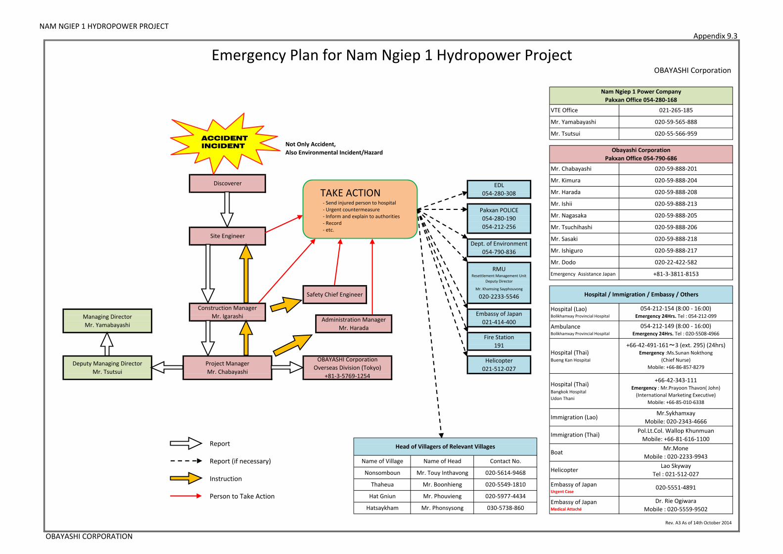
SP20 Emergency Preparedness
Referring to the emergency action plan in Appendix 9.3, the emergency response
procedures, emergency contact numbers and communication and reporting
procedures will be clearly displayed and each staff always carry it.
First aid kits will be prepared at each site accordingly.
Hazardous materials will be stored in the permitted area only and according to the
instruction by the authorities.
When working at heights, the correct PPE such as safety harnesses and hard hats
must be worn. The conditions of safety equipment must be checked every day.
The area under the high working area shall have limited entry.
Due to the location of the works being so close to the Nam Ngiep River, heavy rainfall
can cause rapid increase in water levels.
The safety control plan against flood and evacuation procedure is as follows:
1) Monitoring for safety control plan against flood shall be based on the following
measures described below:
- Weather forecast from the Local Bureau of meteorology
- Analysis of water discharge based on survey monitoring data
- Visual monitoring of water level gauge by watchman along Inlet/Outlet
site
2) When there is a forecast of heavy rain, watchman shall observe elevation of water
level carefully.
3) Warning shall be given when the water level rises rapidly, (Re-Regulation Dam
describes an increase of 1.5m per hour)
4) Watchman shall follow the reporting procedure of the Emergency Action Plan in
Appendix 9.3. Evacuation shall be carried out immediately and shall follow the
required time (8 hours). Evacuation procedure for safety control plan is described
as follows:
(i) After confirmation alert, the safety officer shall provide signal voice (whistle
and/or siren) as commencement for immediate evacuation of all
construction materials (includes excavated soil, rock), equipment and tools,
and workers to higher ground.
(ii) After the removal of all materials, equipment and tools, attendance of
workers shall be checked and confirmed after the evacuation.
(iii) The Safety officer will do a final check of whole area to ensure the
evacuation process is completed.

NAM NGIEP 1 HYDROPOWER PROJECT DWP and SS-ESMMP for Construction of River Diversion Structure Works at Inlet and Outlet
NNP1-MS-MD-006-A1
OBAYASHI CORPORATION Page 33 Revision: A1 November 2014
During structural works workers will be required to work at heights and also confined
spaces.
Correct PPE such as safety harnesses and scaffolding shall be used when applying
shotcrete at large heights. If an area is considered too dangerous for workers
machines will be used.
Scaffolding will be checked by safety staff before it is allowed to be used for work.
The appropriate risk assessment of each particular activity shall be carried out and if
deemed too high of risk, necessary measures will be taken to ensure the safety of
workers.
An emergency drill can be conducted as part of the emergency action plan, in the lead
up to the wet season.
The safety control on site will be changed, revised and added every time in accordance
with occurrence of a dangerous situation and/or with the Owner’s comments.
SP21 Cultural Resource
If the Contractor is to find any new physical or cultural resources during construction, the
Contractor shall stop the works and inform the Owner immediately and follow the Chance
Find Procedures outlined below.
The Environmental mitigation plan will be changed, revised and added in accordance
with the occurrence of adverse impact to the surrounding environment and social
environment and the Owner’s comments.
8.5 Chance Find Procedures
Objectives of Chance Find Procedures are to; (a) minimize impacts to resources from all
NNP1 related activities and (b) to ensure that any artifacts uncovered are appropriately
recorded, documented and reported to the appropriate line agencies.
If any fossil or cultural item of significance is found the Contractor will promptly give notice
to the owner. This follows the guidelines stated in the Civil Works Contract “CWC” Clause
4.25 regarding Fossil and Artifacts.
Chance find procedures as described in Contractors EMMP-CP Sub-plan Appendix 2.1 Sub-
Plan for Civil Works, “21:Cultural Resources” The following steps will be implemented in the
event that previously unidentified artifacts are identified:
i. The Contractor shall immediately cease operations in areas where
artifacts/archaeological finds are unearthed and immediately inform NNP1 Site
Manager.
ii. The Owner will consult the Head of Village and Culture and Tourism
Administration Office to obtain advice regarding the next steps.
iii. The Contractor to recommence work only after the Culture and Tourism Office has
provided official notification accordingly.

NAM NGIEP 1 HYDROPOWER PROJECT DWP and SS-ESMMP for Construction of River Diversion Structure Works at Inlet and Outlet
NNP1-MS-MD-006-A1
OBAYASHI CORPORATION Page 34 Revision: A1 November 2014
9. Appendix
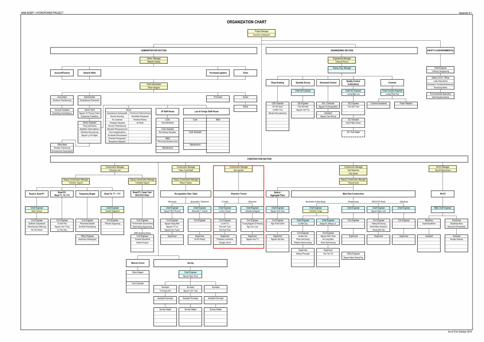
9.1 Organization of Diversion Tunnel Inlet & Outlet
9.2 Construction Schedule of Diversion Tunnel Inlet & Outlet
9.3 Emergency Action Plan
9.4 Working Drawings Inlet & Outlet Structure
9.5 Resources of Diversion Tunnel Inlet & Outlet
9.6 Temporary Facility Layout of Diversion Tunnel Inlet & Outlet
9.7 Construction Sequence of Inlet & Outlet Structure
9.8 Inspection and Test Plans (ITP)
9.9 Sub-plans for ESMMP-CP
9.10 Environmental Management Active Table
NAM NGIEP 1 HYDROPOWER PROJECT DWP & SS-ESMMP for Construction of River Diversion Structure Works at Inlet and Outlet
NNP1-MS-MD-006-A1
OBAYASHI CORPORATION Revision: A1 November 2014
APPENDIX 9.1
Organization of Diversion Tunnel Inlet & Outlet
NAM NGIEP 1 HYDROPOWER PROJECT Appendix 9.1
As of 31st October 2014
Supervisor
Alexander T. Audian
Supervisor
Akio Igarashi
Chief Engineer
Toshihiko Tange
Civil Engineer Civil Engineer
Kittiphas Moonmueang
Office Engineer
Temporary Brigde
Civil Engineer
Phanmaha Ekalath
Salurmseng Sayjoumoua
Civil Engineer
(OBC Building Works)
Supervisor
Civil Engineer
Re-regulation Dam / Dyke
Surveyer
Supervisor
(Grouting)
Civil Engineer
(Excavation / Diversion) (Tunnel) (Structure) (Excavation & Dam Body) (Powerhouse)
Supervisor
Ho Phi Hoang
Hoang Dinh Noi
(RCC/CVC Plant)
ORGANIZATION CHART
Project Manager
Kazuhiko Chabayashi
Issara Burakhorn
M & E Manager
Main Dam Construction M & E
Chief Engineer M&E Chief Engineer
Ryuichi Miyanohara
Chief Engineer Chief Engineer
ENGINEERING SECTION SAFETY & ENVIRONMENTAL
Environmental Specialist
Road A, Road P1
Civil Engineer
Chief Engineer
Supervisor Supervisor
Road P2,
Road T1, T2, T13
Truong Nguyen Di Khuong
Do Van Khanh
Civil Engineer
Vo Anh Pha
Nguyen Van Trung
Le Tien Hoa
Keita Tamura
Civil Engineer
Saikham Vanpaseuth
Khammeung Chittavong
Diversion Tunnel
Hoang Hai Duong
Supervisor
Boualay Thamavong
Khonesavanh Keophaserth
Assistant
Material Control
Sakda Pongsuk
Fuel Controler
Tinnawit Sriputthirat
Civil Engineer
Kham Nammavong
Assistant
Hua Tan Tai
Survey
Supervisor
Mechanic Erectrician
Construction Manager
Keiji Sasaki
Maintenance
Construction Manager
Le Duc Chuyen
Civil Engineer
Chief EngineerChief Engineer
(Structure)
Nguyen Binh Phuong
Nguyen Hong Minh
Civil Engineer
Deputy Construction Manager
Hiroyuki Iyota
Chief Engineer Chief Engineer
Nguyen Anh Quoc
Chief Engineer
Nguyen Ngoc Liem
Store Keeper
Survey Helper Survey Helper
Deputy Construction Manager
Assistant Surveyer Assistant Surveyer
Nguyen Duc Tuyen
Nguyen Tri Tuc
Surveyer Surveyer
Chief Engineer
Nguyen Ngoc Duan
To Hoang Anh Nguyen Van Tung
Bui Xuan Thai
Thinkonenapha Sybounhueang
Chief Engineer
Assistant Surveyer
Survey Helper
Deputy Construction Manager
Tomohiro Taguchi
Civil Engineer Civil Engineer Civil Engineer
Songpol Janoh
Yoshitake Higuchi
Ananhxay Insiziengmai Konglor Sotouky
Shopheap NounNgo Thanh Danh Vu Minh Duc Sergio M. Adducul Jr.Le Anh Tu
Dante Bello Anastacio Bounlone Phomphakdy
Phaimany Lounthone Nguyen Huu Tri Nguyen Gia Hieu Pham Hai Duong Ho Cong Minh
Supervisor Ha Bac Son Nguyen Minh Thien
Tran Anh Tuan Ngo Van LuanSombath Khamtayang
Cook
Cook Assistant
Bounpheng Xayyasan
Deputy Construction Manager
Mitsuo Fukatsu
Admin Assistant
Yeng Leenhiavue
Jedsada Sanggred
CONSTRUCTION SECTION
Phomma Phongoudon
Bounphone Sipaserth
Construction Manager
Tran Anh Tuan
Moneta Khounphachan
Le Minh Truc
Tran Anh Kiet
QC Assistant
Nguyen Thi Hoang Minh
Nguyen Cam Nhung
Assistant
Nguyen Viet Thu
Huynh Ngoc Quyen
Souaxiong Briatu
Boutsakorn Somphanthabansouk
Luong Ngoc Loc Luong Pham Duy
QC EngineerQS Engineer
Chief Contract EngineerChief QC EngineerChief QS Engineer
Public RelationContract assistanatDoc. Controller
Santi Sayakoummane
Loley Xayouthone
Safety & Envi. Officer
Chief Engineer
Vanhxay Sengsavang
ADMINISTRATION SECTION
Admin. Manager
Makoto Harada
Chief Admistrator
Shion Ishiguro
ClinicPurchase/LogisticsAccount/Finance General Affair
Takayuki Kimura
Engineering Manager
Shop Drawing
Deputy Eng. Manager
ContractQuality Control
(Laboratory)Document ControlQuantity Survey
Accountant DoctorPurchaser
Souksamone Souliyamath Chimdavong Thepkhamheuang
Maid
Lao & Foreign Staff House
Nurse
Cook
Somboun Chanthavong
Administrator
Soudsakhone Phomarinh
Admin Clerk
Nguyen Tri Phuong ThanhKhamfong Chanthabouly
Suthasinee Thaebthao
DriverJP Staff House
Sounthala HinpaseuthDavone Sisuvong
Air Lorwansai
Ho Van Quoc
Cook Assistant
Maid
Phouvong Sanyanouvong
Account Assistant
Ningthida Vilamongkhoun
Office Maid
Thongxay Xayyasan
Khamdy Khamsy
Air Kham Veow Boulikhan
CAD Operator
Khamhou Bounyavong
Nguyen Ly Kim Ngan
QC Test Helper
Maintenance
Road P1, Camp Yard
RCC/CVC Plant
Bounom Thammavong
Manothai Phaxaysisounon
Vinut Vongphouthone
Soudsada Khounphanya
Takeo TsuchihashiTakanobu Ishii
Phaivan Xayyavong
Chief Engineer
Hisashi Nagasima
Road T4, T7 ~ T11
Construction Manager
Civil Engineer Chief Engineer
Quarry /
Aggregate Plant
Office Engineer
Nguyen Ngoc Quang Huy
Wittaya Phuangin
Seiji Nagasaka

NAM NGIEP 1 HYDROPOWER PROJECT DWP & SS-ESMMP for Construction of River Diversion Structure Works at Inlet and Outlet
NNP1-MS-MD-006-A1
OBAYASHI CORPORATION Revision: A1 November 2014
APPENDIX 9.2
Construction Schedule of Diversion Tunnel
Inlet & Outlet

Schedule of River Diversion Structure Works at Inlet and Outlet Appendix 9.2
No. Description
1 Relating Tunnel Work
2 Inlet Structure
3 Outlet Structure
Clearing and Demobilization
Survey, Leveling and Compaction Existing Ground
Leveling Concrete
Bottom Slab
Wall Mountain Side
Wall River Side
2015 NOV
5 10 15 20 25 30
2015 OCT
5 10 15 20 25 30
2015 SEP
5 10 15 20 25 30
2015 AUG
5 10 15 20 25 30
2015 JUL
5 10 15 20 25 30
2015 JUN
5 10 15 20 25 30
2015 MAY
5 10 15 20 25 30
Clearing and Demobilization
2015 JAN 2015 FEB 2015 MAR 2015 APR
5 10 15 20 25 30
Top Slab Part I
Top Slab Part II
Top Slab Part III
Dismantle Top Slab Supporting Part I
Dismantle Top Slab Supporting Part II, III
Bottom Slab Part III
20
Wall Part I
Wall Part II
Scaffolding and Supporting for Top Slab
Arch Shape Side Wall Top Portion
Steel Sliding Formwork disassembling
Survey, Leveling and Compaction Existing Ground
Leveling Concrete
Bottom Slab Part I
Bottom Slab Part II
25
Underground excavation DIII Benching
Demobilize to Outlet
Tunnel Invert Concrete
Steel Sliding Formwork Assembling
Tunnel Arch Lining Concrete
20 25 30
Tunnel Entrance (Inlet Side)
Underground excavation DIII Top heading
25 30 5 10 1530 5 10 15 205 10 15

NAM NGIEP 1 HYDROPOWER PROJECT DWP & SS-ESMMP for Construction of River Diversion Structure Works at Inlet and Outlet
NNP1-MS-MD-006-A1
OBAYASHI CORPORATION Revision: A1 November 2014
APPENDIX 9.3
Emergency Action Plan
NAM NGIEP 1 HYDROPOWER PROJECTAppendix 9.3
Rev. A3 As of 14th October 2014
OBAYASHI CORPORATION
Dr. Rie Ogiwara
Mobile : 020-5559-9502
Administration Manager
Mr. Harada
Construction Manager
Mr. Igarashi
Embassy of JapanMedical Attaché
Mr.Sykhamxay
Mobile: 020-2343-4666
Pol.Lt.Col. Wallop Khunmuan
Mobile: +66-81-616-1100
Report (if necessary)
Instruction
054-212-154 (8:00 - 16:00)Emergency 24Hrs. Tel : 054-212-099
+66-42-491-161~3 (ext. 295) (24hrs)Emergency :Ms.Sunan Nokthong
(Chief Nurse)
Mobile: +66-86-857-8279
Hospital (Thai)Bueng Kan Hospital
AmbulanceBolikhamxay Provincial Hospital
054-212-149 (8:00 - 16:00)Emergency 24Hrs. Tel : 020-5508-4966
Report Head of Villagers of Relevant Villages
Pakxan POLICE
054-280-190
054-212-256
Safety Chief Engineer
030-5738-860
EDL
054-280-308
Embassy of JapanUrgent Case
Embassy of Japan
021-414-400
Dept. of Environment
054-790-836
Immigration (Lao)
Immigration (Thai)
Boat
Mr. Ishii
Mr. Nagasaka
Hospital (Thai)Bangkok Hospital
Udon Thani
Mr. Dodo
Mr. Phonsysong
Mr. Phouvieng
Deputy Managing Director
Mr. Tsutsui
+81-3-3811-8153Emergency Assistance Japan
Mr. Sasaki
Mr. Ishiguro 020-59-888-217
Project Manager
Mr. Chabayashi
OBAYASHI Corporation
Overseas Division (Tokyo)
+81-3-5769-1254
Hospital (Lao)Bolikhamxay Provincial HospitalManaging Director
Mr. Yamabayashi
Hospital / Immigration / Embassy / Others
RMUResettlement Management Unit
Deputy Director
Mr. Khamsing Sayphouvong
020-2233-5546
+66-42-343-111Emergency : Mr.Prayoon Thavon( John)
(International Marketing Executive)
Mobile: +66-85-010-6338
020-22-422-582
020-59-888-218
Helicopter
021-512-027
020-59-888-205
020-59-565-888
Mr. Tsutsui 020-55-566-959
020-59-888-204
020-59-888-213
Mr. Harada 020-59-888-208
020-59-888-201
020-59-888-206Mr. Tsuchihashi
Hatsaykham
Emergency Plan for Nam Ngiep 1 Hydropower Project
Not Only Accident,
Also Environmental Incident/Hazard
Discoverer
Site Engineer
Fire Station
191
Nam Ngiep 1 Power Company
Pakxan Office 054-280-168
Obayashi Corporation
Pakxan Office 054-790-686
OBAYASHI Corporation
Mr. Chabayashi
Mr. Kimura
VTE Office 021-265-185
Mr. Yamabayashi
Person to Take Action
HelicopterLao Skyway
Tel : 021-512-027
Name of Head
Mr. Touy Inthavong
Mr. Boonhieng 020-5551-4891
Mr.Mone
Mobile : 020-2233-9943Contact No.
020-5614-9468
020-5549-1810
020-5977-4434Hat Gniun
Thaheua
Nonsomboun
Name of Village
ACCIDENT
INCIDENT
TAKE ACTION- Send injured person to hospital- Urgent countermeasure- Inform and explain to authorities- Record- etc.

NAM NGIEP 1 HYDROPOWER PROJECT DWP & SS-ESMMP for Construction of River Diversion Structure Works at Inlet and Outlet
NNP1-MS-MD-006-A1
OBAYASHI CORPORATION Revision: A1 November 2014
APPENDIX 9.4
Working Drawings
for Inlet & Outlet Structure Works
- Working drawings have been submitted separately.
NAM NGIEP 1 HYDROPOWER PROJECT DWP & SS-ESMMP for Construction of River Diversion Structure Works at Inlet and Outlet
NNP1-MS-MD-006-A1
OBAYASHI CORPORATION Revision: A1 November 2014
APPENDIX 9.5
Resource for Inlet & Outlet Structure Works

NAM NGIEP 1 HYDROPOWER PROJECT Detailed Works Program for Construction of River Diversion Structure Works at Inlet and Outlet
Appendix 9.5
9.5 Resources
1 2 3 4 5 6 7 8 9 10 11 12
1 Inlet Diversion Tunnel 1. Excavator (0.7 m3) 1 1 1 1 1
2. Bulldozer (21 ton) 1
3. Compactor Roller (10 ton) 1
4. Motor Grader (12 ton) 1
5. Mobile Concrete Pump Truck (30 m3/h) 2 2 2 2 2
6. Concrete Mixer Truck (5m3) 5 5 5 5 5
7. Mobile Crane Truck (25 ton, 35 ton) 2 2 2 2 2
8. Unit Truck with Crane (5 ton) 1 1 1 1 1
9. Service Truck (2-4 tons) 2 2 2 2 2
10. Air Compressor (375 cfm) 1 1 1 1 1
11. Generator (600 kVA) 1 1 1 1 1
12. Concrete Vibrator 4 4 4 4 4
13. Submersible Pump (2” - 6”) 4 4 4 4 4
14. Welding Machine 4 4 4 4 4
15. Cutter machine 2 2 2 2 2
16. Bar Bender machine 1 1 1 1 1
17. Scaffolding 600 1200 1200
OBAYASHI CORPORATION Revision : A1
No. Location Resource
Working Month
Remark2015
NAM NGIEP 1 HYDROPOWER PROJECT Detailed Works Program for Construction of Inlet and Outlet Structure Works
Appendix 9.5
1 2 3 4 5 6 7 8 9 10 11 12
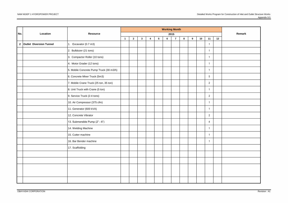
2 Outlet Diversion Tunnel 1. Excavator (0.7 m3) 1
2. Bulldozer (21 tons) 1
3. Compactor Roller (10 tons) 1
4. Motor Grader (12 tons) 1
5. Mobile Concrete Pump Truck (30 m3/h) 1
6. Concrete Mixer Truck (5m3) 5
7. Mobile Crane Truck (25 ton, 35 ton) 2
8. Unit Truck with Crane (5 ton) 1
9. Service Truck (2-4 tons) 2
10. Air Compressor (375 cfm) 1
11. Generator (600 kVA) 1
12. Concrete Vibrator 2
13. Submersible Pump (2” - 6”) 4
14. Welding Machine 1
15. Cutter machine 1
16. Bar Bender machine 1
17. Scaffolding
OBAYASHI CORPORATION Revision : A1
RemarkNo. Location Resource
Working Month
2015
NAM NGIEP 1 HYDROPOWER PROJECT DWP & SS-ESMMP for Construction of River Diversion Structure Works at Inlet and Outlet
NNP1-MS-MD-006-A1
OBAYASHI CORPORATION Revision: A1 November 2014
APPENDIX 9.6
Temporary Facility Layout for River Diversion
Tunnel Inlet & Outlet

D-1
8
6,0
0
6,00
5,35
5,3
5
RestArea
Toilet
Generator
Air CompMobile
Equipment
Mobile Crane
Concrete Mixer Truck
Moblie Concrete Pump
Unit Truck with Crane
Service Truck
Oiler Truck
Excavator
REVISION
No.
DESCRIPTION
DATE
CON
TRACTOR:
DRAWIN
G NO
.SCALE:
TITLEN
AM N
GIEP 1 POW
ER COM
PANY
OW
NER:
OBAYASHI CO
RPORATIO
NREV
NAM
NGIEP 1 HYDRO
POW
ER PROJECT
DESIGNED
DRAWN
CHECKED
ISSUED
TITLEN
AME
DATE
1/500
LAYOU
T PLAN TEM
PORARY FACILITY AT IN
LET
WELDIN
D SHOP
AND STO
RAGE
CEMEN
T STORAGE
TEMPO
RARY
BARED WIRE FENCE
BARED WIRE FENCE
BARED WIRE FENCE
BARED WIRE FENCE
BARED WIRE FENCE
WC
STEEL RIBFABRICATIO
N YARD
TEMP M
IXER HOU
SE
GEN
ERA TOR YARD
PLUM
BER CAMP
ELECTRICAL STORAGE
WATER RESEVO
IRSIZE = 3x3x1 m
.
SEDNM
ENT PO
ND
FOR W
ASHED M
IXERSIZE = 4x4x1 m
.
LAYOU
T PLANBATCHIN
G PLANT
REBAR FABRICATION
YARD
FORM
WO
RK FABRICATION
YARD
LAYOUTBATCHING PLANT
RIGHT TUNNELLING CO.,LTD.REVIEWED :
NAM NGIEP 1 HYDROPOWER PROJECT
-
CHECKED :APPROVED :
DATE
DESIGNED :DRAWN :CHECKED :
NATTAVUT P.KACHAGORN S.
DRAWING NO.REV.
.................................................................................................................................
.........................
DATEAPPROVED
CHECKEDDATE
REVIEWEDDATE
REV.
01 02 03
-DESCRIPTION
SUBMITTED :SURACHAT D.
OBAYASHI CORPORATION
SHEET NO.-
DATECONTRACT NO.
PREFEASIBILITY STUDYFEASIBILITY STUDYBASIC DESIGN
TENDER DESIGNCONSTRUCTION DESIGN
AS-BUILT DRAWING
INFORMATIONREFERENCE
REVIEW & COMMENTAPPROVAL
PHASE :
ATTN FOR :
............................................................................................................................................................................
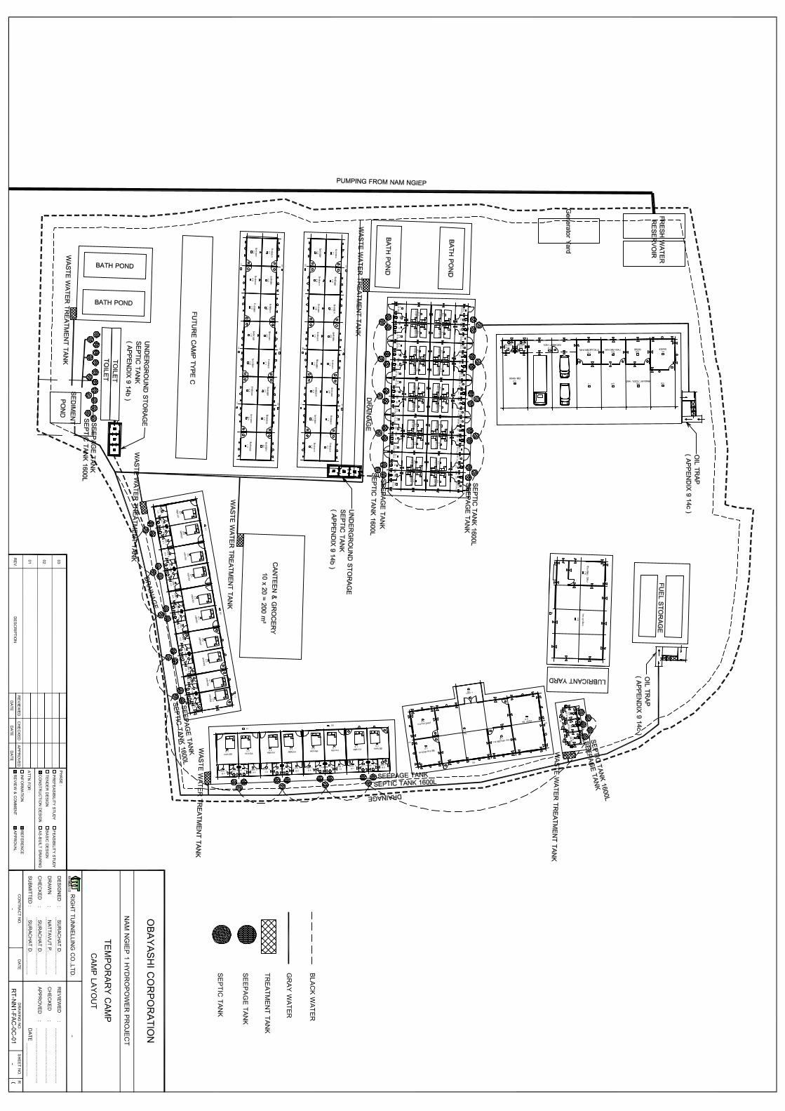
BLACK WATER
GRAY W
ATER
SEEPAGE TANK
SEPTIC TANK
TREATMENT TANK
CAMP LAYO
UTTEM
PORARY CAM
P
RT-NN1-FAC-0C-01
RIGHT TUNNELLING
CO.,LTD.
REVIEWED :
NAM NG
IEP 1 HYDROPO
WER PROJECT
-
CHECKED :
APPROVED :
DATE
DESIGNED :
DRAWN :
CHECKED :
SURACHAT D.
NATTAVUT P.
SURACHAT D.
DRAWING
NO.REV.00
...........................................
...........................................
...........................................
.........................
DATEAPPRO
VEDCHECKED
DATEREVIEW
EDDATE
REV.
01 02 03
-DESCRIPTION
SUBMITTED :
SURACHAT D.
OBAYASHI CO
RPORATIO
N
SHEET NO.-
DATECO
NTRACT NO.
PREFEASIBILITY STUDYFEASIBILITY STUDYBASIC DESIGN
TENDER DESIGNCO
NSTRUCTION DESIGN
AS-BUILT DRAWING
INFORM
ATIONREFERENCE
REVIEW & COM
MENT
APPROVAL
PHASE :
ATTN FOR :
...........................................
...........................................
...........................................
...........................................

NAM NGIEP 1 HYDROPOWER PROJECT DWP & SS-ESMMP for Construction of River Diversion Structure Works at Inlet and Outlet
NNP1-MS-MD-006-A1
OBAYASHI CORPORATION Revision: A1 November 2014
APPENDIX 9.7
Construction Sequence of Inlet & Outlet
Structure Works

1 : 0.3
1 : 0.3
1 : 0.5
1 : 0.5
EL
.18
1.0
00
EL
.18
5.3
55
4355 5000
EL
.19
0.3
55
EL
.17
9.0
00
EL
.19
1.8
55
2000 1500
EL
. 17
9.0
00m
EL
. 18
6.0
00m
Div
ers
ion
tun
nel
Div
ers
ion
inle
t
EL
. 18
4.0
00m
EL
.18
5.3
55
INL
ET
AX
IS
1 : 0.5
1 : 0.3
150
00
Se
qu
en
ce
of In
let S
tructu
re C
onstru
ctio
n
EL
.18
1.0
00
DIII T
ype
Excavatio
n
Sh
otc
rete
t=2
50
Ste
p 1
Mo
biliz
atio
n
Afte
r op
en
exca
va
tion
an
d s
lop
e p
rote
ctio
n,
un
de
rgro
un
d e
xca
va
tion
typ
e D
III (~S
ta 1
5.0
0) a
t inle
t
co
mp
lete
d. T
he
inle
t stru
ctu
re w
ork
s o
f div
ers
ion
tun
ne
l
will b
e m
ob
ilize
d a
nd
co
mm
en
ce
me
nt w
ork
.
7000
7000
EL
.18
1.1
16
EL
.19
0.3
55
EL
.19
1.8
55
EL
.20
0.5
00
Ste
el S
up
po
rt
H-2
00
Fo
rep
olin
g
DB
25
L=
30
00
Sh
otc
rete
t=2
50
Fo
rep
olin
g
DB
25
L=
30
00
Ro
ck B
olt
DB
25
L=
40
00
Inle
t Stru
ctu
re
Inle
t Stru
ctu
re
Orig
ina
l Gro
un
d S
urfa
ce
Se
ctio
n

1 : 0.5
EL
.17
8.9
00
EL
.18
4.4
00
g =
-39.0
69%
EL
.18
3.9
00
EL
.18
6.0
00
151
00
143
00
1700
INL
ET
AX
ISE
L.1
85.3
55
Orig
ina
l Gro
un
d S
urfa
ce
Le
ve
ling
an
d c
om
pa
ctio
n
exis
ting
gro
un
dE
L.1
81.0
00
Div
ers
ion
tun
nel
Div
ers
ion
inle
t
Se
qu
en
ce
of In
let S
tructu
re C
onstru
ctio
n
1 : 0.3
1 : 0.3
2000
Vary
Vary
2000
EL
.18
5.3
55 V
ary
EL
.17
8.9
00
INL
ET
AX
IS
Botto
m o
f Levelin
g C
oncre
te
Exca
va
tion
, leve
ling
an
d c
om
pa
ctio
n th
e e
xis
ting
gro
un
d u
ntil re
ach
to b
otto
m o
f leve
ling
co
ncrte
leve
l (Le
ve
ling
co
ncre
te is
10
0 m
m th
ick u
nd
er
the
ba
se
sla
b)
Ste
p 2
Le
ve
ling
an
d
Co
mp
actio
n
Exis
ting
Gro
un
d
Se
ctio
n
Se
qu
en
ce
of In
let S
tructu
re C
onstru
ctio
n
1 : 0.5
EL
.17
9.0
00
EL
.18
4.5
00
g =
-39.0
69%
EL
.18
4.0
00
EL
.18
6.0
00
150
00
145
00
1500
INL
ET
AX
ISE
L.1
85.3
55
Orig
ina
l Gro
un
d S
urfa
ce
Le
ve
ling
co
ncre
te
Div
ers
ion
tun
nel
Div
ers
ion
inle
t
1 : 0.3
1 : 0.3
2000
Vary
2000
Vary
EL
.17
9.0
00
EL
.18
5.3
55
INL
ET
AX
IS
Top
Levelin
g C
oncre
te
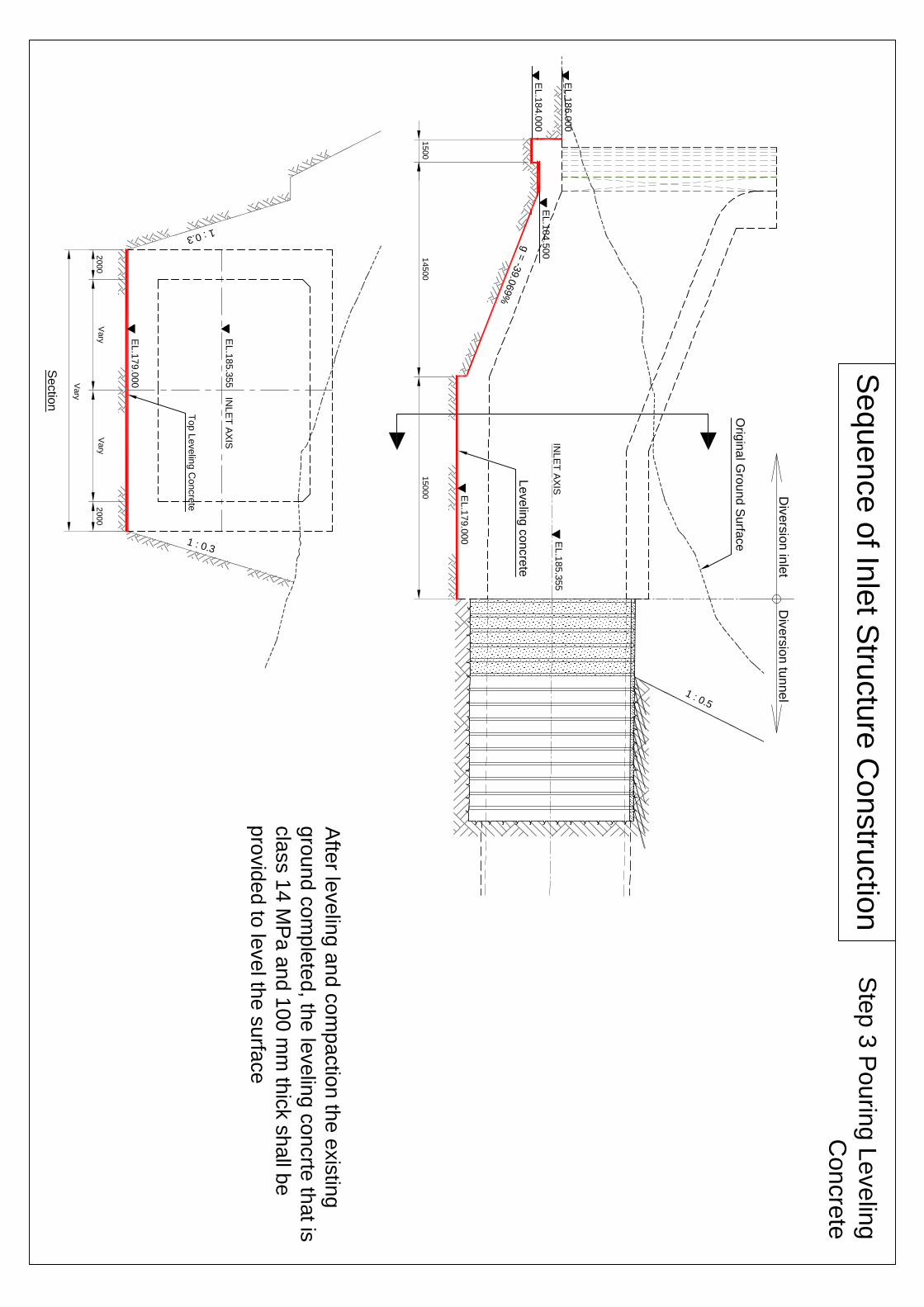
Afte
r leve
ling
an
d c
om
pa
ctio
n th
e e
xis
ting
gro
un
d c
om
ple
ted
, the
leve
ling
co
ncrte
tha
t is
cla
ss 1
4 M
Pa
an
d 1
00
mm
thic
k s
ha
ll be
pro
vid
ed
to le
ve
l the
su
rface
Ste
p 3
Po
urin
g L
eve
ling
Co
ncre
te
Vary
Se
ctio
n
1 : 0.5
EL
.18
1.1
16
EL
.18
4.0
00
150
00
125
00
1500
INL
ET
AX
ISE
L.1
85.3
55
Orig
ina
l Gro
un
d S
urfa
ce
EL
.18
1.0
00
g =
-0.7
662%
g =
-39.0
69%
EL
.18
6.0
00
1
2
3
EL
.17
9.0
00
2000
Bo
ttom
sla
b
co
ncre
ting
Div
ers
ion
tun
nel
Div
ers
ion
inle
t
1 : 0.3
1 : 0.3
Se
ctio
n
2000
2000
Vary
EL
.17
9.0
00
EL
.18
5.3
55
INL
ET
AX
IS
Vary
EL.1
81.0
00
~ 1
81
.116
Vary
Vary
Se
qu
en
ce
of In
let S
tructu
re C
onstru
ctio
nS
tep
4 B
otto
m S
lab
Co
nstru
ctio
n
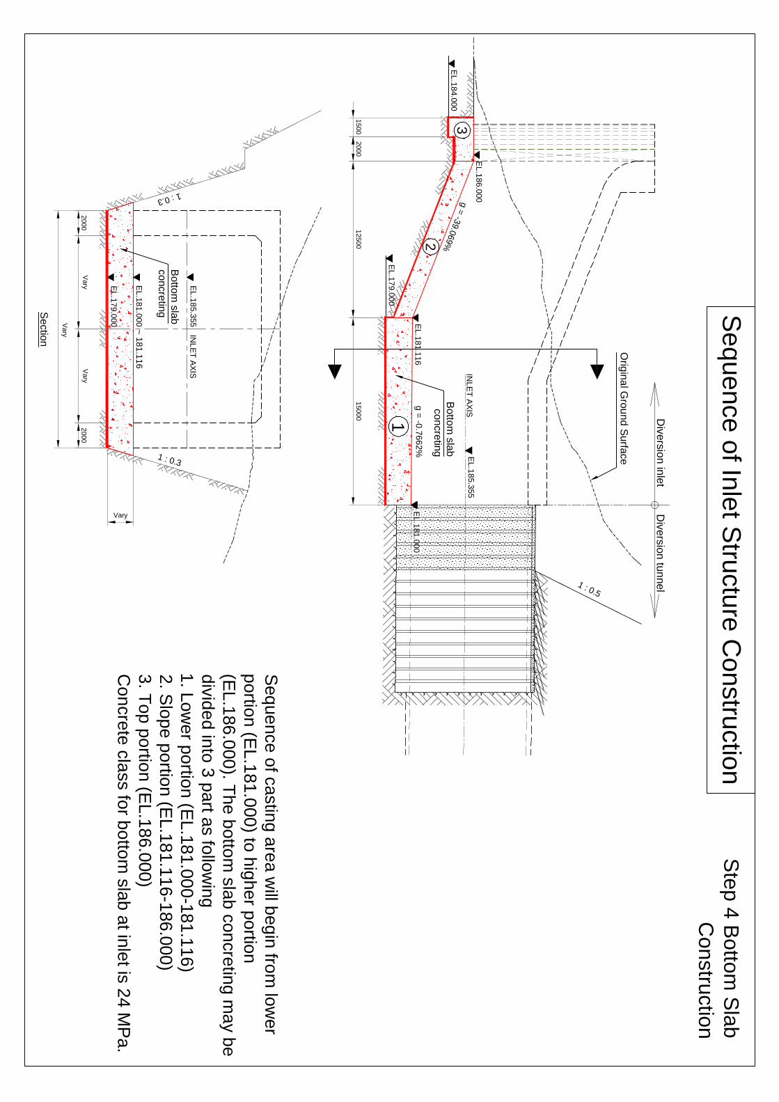
Se
qu
en
ce
of c
astin
g a
rea
will b
eg
in fro
m lo
we
r
po
rtion
(EL
.18
1.0
00
) to h
igh
er p
ortio
n
(EL
.18
6.0
00
). Th
e b
otto
m s
lab
co
ncre
ting
ma
y b
e
div
ide
d in
to 3
pa
rt as fo
llow
ing
1. L
ow
er p
ortio
n (E
L.1
81
.00
0-1
81
.11
6)
2. S
lop
e p
ortio
n (E
L.1
81
.11
6-1
86
.00
0)
3. T
op
po
rtion
(EL
.18
6.0
00
)
Co
ncre
te c
lass fo
r bo
ttom
sla
b a
t inle
t is 2
4 M
Pa
.
Bo
ttom
sla
b
co
ncre
ting
1 : 0.5
g =
-39.0
69%
EL
.18
6.0
00
150
00
145
00
1500
EL
.18
1.0
00
EL
.18
1.1
16
EL
.19
0.3
55
EL
.19
1.8
55
C.J
.
C.J
.
C.J
.
@ ~3.0 m per one lift
100
00
5000
Wa
ll co
ncre
ting
EL
.19
2.3
08
Se
qu
en
ce
of In
let S
tructu
re C
onstru
ctio
n
Div
ers
ion
tun
nel
Div
ers
ion
inle
t
1 : 0.3
1 : 0.3
2388
EL
.17
9.0
00
EL.1
81.0
00
~ 1
81
.116
2388
Vary
Vary
EL
.18
5.3
55
INL
ET
AX
IS
C.J
.
C.J
.
C.J
.
Vary
@ ~3.5 m per one lift
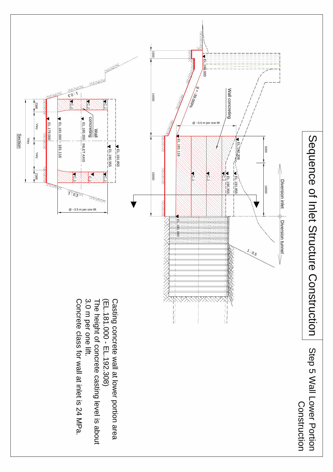
Wa
ll
co
ncre
ting
Ste
p 5
Wa
ll Lo
we
r Po
rtion
Co
nstru
ctio
n
Ca
stin
g c
on
cre
te w
all a
t low
er p
ortio
n a
rea
(EL
.18
1.0
00
- EL
.19
2.3
08
)
Th
e h
eig
ht o
f co
ncre
te c
astin
g le
ve
l is a
bo
ut
3.0
m p
er o
ne
lift.
Co
ncre
te c
lass fo
r wa
ll at in
let is
24
MP
a.
C.J
.
C.J
.
Se
ctio
n
EL
.19
0.3
55
EL
.19
1.8
55
C.J
.

Se
qu
en
ce
of In
let S
tructu
re C
onstru
ctio
n
1 : 0.5
EL
.18
6.0
00
150
00
125
00
3000
Orig
ina
l Gro
un
d S
urfa
ce
EL
.18
1.0
00
EL
.18
1.1
16
EL
.19
0.3
55
EL
.19
1.8
55
EL
.19
2.3
08
EL
.19
6.4
14
@ ~ 3.0 m per one lift
C.J
.
C.J
.
C.J
.
C.J
.
C.J
.
Wa
ll co
ncre
ting
Th
is p
art o
f wa
ll will b
e c
aste
d
tog
eth
er w
ith to
p s
lab
Div
ers
ion
tun
nel
Div
ers
ion
inle
t
1 : 0.3
1 : 0.3
1 : 0.3
1500
1500
190
00
7000
7000
2000
@ ~3.5 m per one lift
To
p S
lab
Cha
mfe
r
500
x5
00
mm
Wa
ll
co
ncre
ting
Wa
ll
co
ncre
ting
Ste
p 6
Wa
ll Hig
he
r Po
rtion
Co
nstru
ctio
n
Ca
stin
g c
on
cre
te w
all a
t hig
he
r po
rtion
are
a
(EL
.18
1.1
16
- EL
.19
6.4
14
)
Th
e h
eig
ht o
f co
ncre
te c
astin
g le
ve
l is a
bo
ut
3.0
m p
er o
ne
lift.
Co
ncre
te c
lass fo
r wa
ll at in
let is
24
MP
a.
Se
ctio
n
C.J
.
C.J
.
C.J
.
C.J
.C
.J.
C.J
.
C.J
.
C.J
.
C.J
.C
.J.
C.J
.
C.J
.
C.J
.
C.J
.C
.J.

1 : 0.5
EL
.18
4.0
00
EL
.18
6.0
00
Orig
ina
l Gro
un
d S
urfa
ce
EL
.18
1.0
00
INL
ET
AX
ISE
L.1
85.3
55
100
00
Exte
nd
arc
h s
ha
pe
top
po
rtion
of s
ide
wa
ll
Div
ers
ion
tun
nel
Div
ers
ion
inle
t
1 : 0.3
1 : 0.3
2000
EL
.17
9.0
00
EL.1
81.0
00
~ 1
81
.116
2000
Vary
Vary
EL
.18
5.3
55
INL
ET
AX
IS
1000
2000
3000
4000
5000
500
Exte
nd
arc
h s
ha
pe
top
po
rtion
of s
ide
wa
ll
Se
qu
en
ce
of In
let S
tructu
re C
onstru
ctio
nS
tep
7 E
xte
nd
the
Arc
h S
ha
pe
To
p P
ortio
n o
f Sid
e W
all
1 In
sta
ll sca
ffold
ing
an
d s
up
po
rting
for s
offit fo
rm
2 C
hip
pin
g c
on
cre
te s
urfa
ce
for c
on
stru
ctio
n jo
int
3 In
sta
ll arc
h s
ha
pe
form
wo
rk a
cco
rdin
g to
su
rve
y
alig
nm
en
t
4 P
ou
ring
co
ncre
te u
ntil re
ach
to s
pe
cifie
d le
ve
l
EL
.19
6.4
14
Vary
Se
ctio
n

1 : 0.5
EL
.18
4.0
00
EL
.18
6.0
00
EL
.18
1.0
00
INL
ET
AX
ISE
L.1
85.3
55
1
2
3
EL
.19
1.8
55
EL
.20
0.5
00
3000
2500
150
00
100
00
EL
.18
1.1
16
g =
-39.0
69%
g =
-0.7
662%
g =
-39.0
69%
EL
.19
7.7
15
EL
.19
6.4
14
To
p s
lab
co
ncre
ting
Div
ers
ion
tun
nel
Div
ers
ion
inle
t
Se
qu
en
ce
of In
let S
tructu
re C
onstru
ctio
n
1 : 0.3
1 : 0.3
1 : 0.3
1500
1500
190
00
7000
7000
2000
Vary
Cha
mfe
r
500
x5
00
mm
Vary Vary
Ste
p 8
To
p S
lab
Co
nstru
ctio
n
Se
ctio
n
4086
Orig
ina
l Gro
un
d S
urfa
ce
To
p s
lab
co
ncre
ting
Se
qu
en
ce
of c
astin
g a
rea
will b
eg
in fro
m lo
we
r
po
rtion
(EL
.19
1.8
55
) to h
igh
er p
ortio
n
(EL
.20
0.5
00
). Th
e to
p s
lab
co
ncre
ting
ma
y b
e
div
ide
d in
to 3
pa
rt as fo
llow
ing
1. L
ow
er p
ortio
n (E
L.1
91
.85
5)
2. S
lop
e p
ortio
n (E
L.1
91
.85
5-1
97
.71
5)
3. T
op
po
rtion
(EL
.19
7.7
15
-20
0.5
00
)
Co
ncre
te c
lass fo
r top
sla
b a
t inle
t is 2
4 M
Pa
.

1 : 0.5
EL
.18
4.0
00
EL
.18
6.0
00
EL
.18
1.0
00
INL
ET
AX
ISE
L.1
85.3
55
EL
.19
1.8
55
EL
.20
0.5
00
3000
2500
150
00
EL
.18
1.1
16
100
00
g =
-39.0
69%
g =
-39.0
69%
g =
-0.7
662%
100
00
EL
.19
7.7
15
Div
ers
ion
tun
nel
Div
ers
ion
inle
t
1 : 0.3
1 : 0.3
2000
EL
.17
9.0
00
EL.1
81.0
00
~ 1
81
.116
2000
Vary
Vary
EL
.18
5.3
55
INL
ET
AX
IS
Vary
Se
ctio
n
EL
.19
1.8
55
Vary 4355 5000 1500
EL
.19
0.3
55
Se
qu
en
ce
of In
let S
tructu
re C
onstru
ctio
nS
tep
9 D
em
ob
iliza
tion
Dis
ma
ntle
all fo
rmw
ork
, cle
an
ing
an
d
de
mo
biliz
atio
n

Se
qu
en
ce
of O
utle
t Stru
ctu
re C
onstru
ctio
n
1 : 1
EL
.17
6.0
00
EL
.18
0.3
55
EL
.18
5.5
00
Div
ers
ion
tun
nel
Div
ers
ion
outle
t
120
00
EL
.18
2.0
00
Tun
ne
l Axis
4355 5000
Co
ncre
te W
all 5
00
mm
Th
ick.
6500
10000
Afte
r co
mp
letio
n o
f arc
h lin
ing
co
ncre
te
of tu
nn
el a
nd
dis
asse
mb
ly th
e s
tee
l
slid
ing
form
wo
rk c
om
ple
ted
as w
ell.
Th
e o
utle
t stru
ctu
re w
ork
of d
ive
rsio
n
tun
ne
l will b
e m
ob
ilize
d a
nd
co
mm
en
ce
me
nt w
ork
Arc
h L
inin
g C
on
cre
te
Inve
rt Co
ncre
te
Ste
p 1
Mo
biliz
atio
n
Co
ncre
te S
lab
50
0m
m T
hic
k.
Orig
ina
l Gro
un
d S
urfa
ce
EL
.17
6.0
00
Orig
ina
l Gro
un
d S
urfa
ce
EL
.18
2.0
00
EL
.18
2.0
00
100
00
6500
Se
ctio
n
10000
Co
ncre
te W
all 5
00
mm
Th
ick.
Co
ncre
te W
all 5
00
mm
Th
ick
EL
.18
0.3
55
EL
.17
5.5
00
Top
Levelin
g C
oncre
te
Co
ncre
te S
lab
50
0m
m T
hic
k.
Tun
ne
l Axis
Inve
rt Co
ncre
te

Se
qu
en
ce
of O
utle
t Stru
ctu
re C
onstru
ctio
nS
tep
2 L
eve
ling
Co
ncre
te
for B
otto
m S
lab
1 : 1
EL
.17
6.0
00
EL
.18
0.3
55
EL
.18
5.5
00
Div
ers
ion
tun
nel
Div
ers
ion
outle
t
120
00
Orig
ina
l Gro
un
d S
urfa
ce
EL
.17
6.0
00
Orig
ina
l Gro
un
d S
urfa
ce
EL
.18
2.0
00
EL
.18
2.0
00
100
00
6500
Se
ctio
n
EL
.18
2.0
00
Tun
ne
l Axis
4355 5000
10000
Co
ncre
te W
all 5
00
mm
Th
ick.
Co
ncre
te W
all 5
00
mm
Th
ick
EL
.18
0.3
55
Le
ve
ling
, Co
mp
actio
n a
nd
Po
ur
Le
ve
ling
Co
ncre
t 10
0m
m T
hic
k
Co
ncre
te W
all 5
00
mm
Th
ick.
Le
ve
ling
, Co
mp
actio
n a
nd
Po
ur
Le
ve
ling
Co
ncre
t 10
0m
m T
hic
k
EL
.17
5.5
00
Top
Levelin
g C
oncre
te
6500
10000
Exca
va
tion
, leve
ling
an
d c
om
pa
ctio
n
the
exis
ting
gro
un
d u
ntil re
ach
to
bo
ttom
of le
ve
ling
co
ncrte
leve
l
(Le
ve
ling
co
ncre
te is
10
0 m
m th
ick
un
de
r the
bo
ttom
sla
b)

Se
qu
en
ce
of O
utle
t Stru
ctu
re C
onstru
ctio
n
1 : 1
EL
.17
6.0
00
EL
.18
0.3
55
EL
.18
5.5
00
Div
ers
ion
tun
nel
Div
ers
ion
outle
t
120
00
Orig
ina
l Gro
un
d S
urfa
ce
EL
.17
6.0
00
Orig
ina
l Gro
un
d S
urfa
ce
EL
.18
2.0
00
EL
.18
2.0
00
100
00
6500
Se
ctio
n
EL
.18
2.0
00
Tun
ne
l Axis
4355 5000
10000
Co
ncre
te W
all 5
00
mm
Th
ick.
Co
ncre
te W
all 5
00
mm
Th
ick
EL
.18
0.3
55
Co
ncre
te W
all 5
00
mm
Th
ick.
EL
.17
5.5
00
Top
Levelin
g C
oncre
te
6500
10000
Ste
p 3
Bo
ttom
Sla
b
Co
nstru
ctio
n
Sla
b 5
00
mm
Th
ick C
on
cre
ting
Sla
b 5
00
mm
Th
ick C
on
cre
ting
Co
nstru
ct c
on
cre
te s
lab
50
0m
m th
ick.
Th
e c
on
cre
te c
lass fo
r sla
b is
21
MP
a
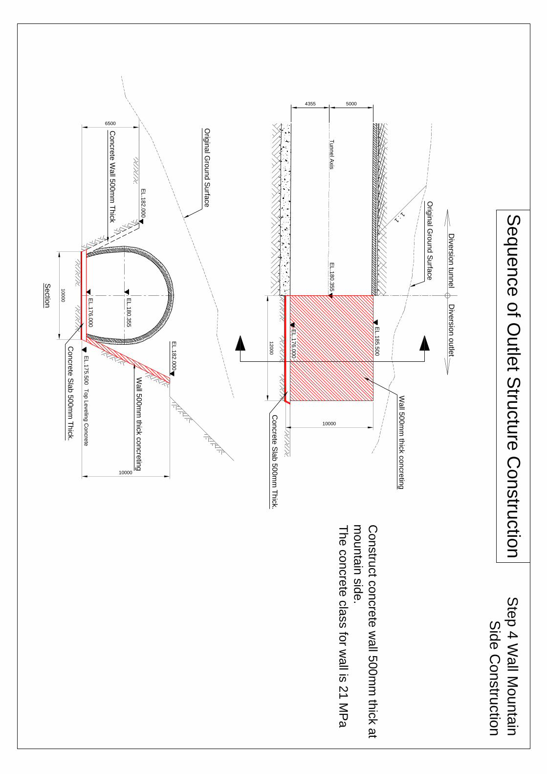
Se
qu
en
ce
of O
utle
t Stru
ctu
re C
onstru
ctio
n
1 : 1
EL
.17
6.0
00
EL
.18
0.3
55
EL
.18
5.5
00
Div
ers
ion
tun
nel
Div
ers
ion
outle
t
120
00
Orig
ina
l Gro
un
d S
urfa
ce
EL
.17
6.0
00
Orig
ina
l Gro
un
d S
urfa
ce
EL
.18
2.0
00
EL
.18
2.0
00
100
00
6500
Se
ctio
n
Tun
ne
l Axis
4355 5000
10000
Wa
ll 50
0m
m th
ick c
on
cre
ting
Co
ncre
te W
all 5
00
mm
Th
ick
EL
.18
0.3
55
Wa
ll 50
0m
m th
ick c
on
cre
ting
EL
.17
5.5
00
Top
Levelin
g C
oncre
te
10000
Ste
p 4
Wa
ll Mo
un
tain
Sid
e C
on
stru
ctio
n
Co
nstru
ct c
on
cre
te w
all 5
00
mm
thic
k a
t
mo
un
tain
sid
e.
Th
e c
on
cre
te c
lass fo
r wa
ll is 2
1 M
Pa
Co
ncre
te S
lab
50
0m
m T
hic
k.
Co
ncre
te S
lab
50
0m
m T
hic
k.

Se
qu
en
ce
of O
utle
t Stru
ctu
re C
onstru
ctio
n
1 : 1
EL
.17
6.0
00
EL
.18
0.3
55
EL
.18
5.5
00
Div
ers
ion
tun
nel
Div
ers
ion
outle
t
120
00
Orig
ina
l Gro
un
d S
urfa
ce
EL
.17
6.0
00
Orig
ina
l Gro
un
d S
urfa
ce
EL
.18
2.0
00
EL
.18
2.0
00
100
00
6500
Se
ctio
n
Tun
ne
l Axis
4355 5000
10000
Co
ncre
te W
all 5
00
mm
Th
ick.
Wa
ll 50
0m
m th
ick c
on
cre
ting
EL
.18
0.3
55
Wa
ll 50
0m
m th
ick c
on
cre
ting
EL
.17
5.5
00
Top
Levelin
g C
oncre
te
10000
Ste
p 5
Wa
ll Riv
er S
ide
Co
nstru
ctio
n
Co
nstru
ct c
on
cre
te w
all 5
00
mm
thic
k a
t
rive
r sid
e.
Th
e c
on
cre
te c
lass fo
r wa
ll is 2
1 M
Pa
Co
ncre
te S
lab
50
0m
m T
hic
k.
Co
ncre
te S
lab
50
0m
m T
hic
k.
6500
Co
ncre
te W
all 5
00
mm
Th
ick.

Se
qu
en
ce
of O
utle
t Stru
ctu
re C
onstru
ctio
n
1 : 1
EL
.17
6.0
00
EL
.18
0.3
55
EL
.18
5.5
00
Div
ers
ion
tun
nel
Div
ers
ion
outle
t
120
00
Orig
ina
l Gro
un
d S
urfa
ce
EL
.17
6.0
00
Orig
ina
l Gro
un
d S
urfa
ce
EL
.18
2.0
00
EL
.18
2.0
00
100
00
6500
Se
ctio
n
Tun
ne
l Axis
4355 5000
10000
Co
ncre
te W
all 5
00
mm
Th
ick.
Co
ncre
te W
all 5
00
mm
Th
ick
EL
.18
0.3
55
EL
.17
5.5
00
Top
Levelin
g C
oncre
te
10000
Co
ncre
te S
lab
50
0m
m T
hic
k.
Co
ncre
te S
lab
50
0m
m T
hic
k.
6500
Ste
p 6
De
mo
biliz
atio
n
Cle
arin
g a
ll ma
teria
ls, c
lea
nin
g a
nd
de
mo
biliz
e
Co
ncre
te W
all 5
00
mm
Th
ick.

NAM NGIEP 1 HYDROPOWER PROJECT DWP & SS-ESMMP for Construction of River Diversion Structure Works at Inlet and Outlet
NNP1-MS-MD-006-A1
OBAYASHI CORPORATION Revision: A1 November 2014
APPENDIX 9.8
Inspection and Test Plans (ITP)
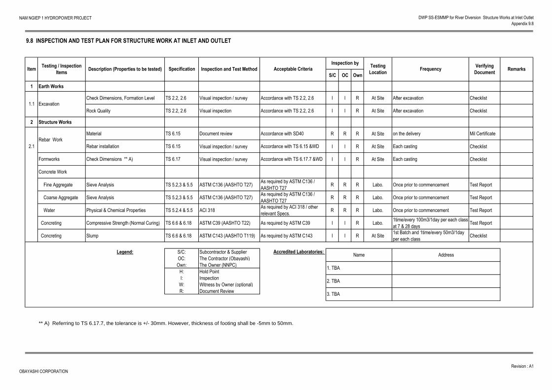
NAM NGIEP 1 HYDROPOWER PROJECT DWP SS-ESMMP for River Diversion Structure Works at Inlet Outlet
Appendix 9.8
S/C OC Own
1 Earth Works
Check Dimensions, Formation Level TS 2.2, 2.6 Visual inspection / survey Accordance with TS 2.2, 2.6 I I R At Site After excavation Checklist
Rock Quality TS 2.2, 2.6 Visual inspection Accordance with TS 2.2, 2.6 I I R At Site After excavation Checklist
2 Structure Works
Material TS 6.15 Document review Accordance with SD40 R R R At Site on the delivery Mil Certificate
2.1 Rebar installation TS 6.15 Visual inspection / survey Accordance with TS 6.15 &WD I I R At Site Each casting Checklist
Formworks Check Dimensions ** A) TS 6.17 Visual inspection / survey Accordance with TS 6.17.7 &WD I I R At Site Each casting Checklist
Concrete Work
Fine Aggregate Sieve Analysis TS 5.2,3 & 5.5 ASTM C136 (AASHTO T27)As required by ASTM C136 /
AASHTO T27R R R Labo. Once prior to commencement Test Report
Coarse Aggregate Sieve Analysis TS 5.2,3 & 5.5 ASTM C136 (AASHTO T27)As required by ASTM C136 /
AASHTO T27R R R Labo. Once prior to commencement Test Report
Water Physical & Chemical Properties TS 5.2.4 & 5.5 ACI 318As required by ACI 318 / other
relevant Specs.R R R Labo. Once prior to commencement Test Report
Concreting Compressive Strength (Normal Curing) TS 6.6 & 6.18 ASTM C39 (AASHTO T22) As required by ASTM C39 I I R Labo.1time/every 100m3/1day per each class
at 7 & 28 daysTest Report
Concreting Slump TS 6.6 & 6.18 ASTM C143 (AASHTO T119) As required by ASTM C143 I I R At Site1st Batch and 1time/every 50m3/1day
per each classChecklist
Legend: S/C: Subcontractor & Supplier Accredited Laboratories:
OC: The Contractor (Obayashi)
Own: The Owner (NNPC)
H: Hold Point
I: Inspection
W: Witness by Owner (optional)
R: Document Review
** A) Referring to TS 6.17.7, the tolerance is +/- 30mm. However, thickness of footing shall be -5mm to 50mm.
Rebar Work
Description (Properties to be tested) Specification Inspection and Test MethodVerifying
DocumentFrequency
9.8 INSPECTION AND TEST PLAN FOR STRUCTURE WORK AT INLET AND OUTLET
ItemTesting / Inspection
ItemsRemarks
Inspection byAcceptable Criteria
Testing
Location
2. TBA
1.1 Excavation
3. TBA
Name Address
1. TBA
OBAYASHI CORPORATIONRevision : A1

NAM NGIEP 1 HYDROPOWER PROJECT DWP & SS-ESMMP for Construction of River Diversion Structure Works at Inlet and Outlet
NNP1-MS-MD-006-A1
OBAYASHI CORPORATION Revision: A1 November 2014
APPENDIX 9.9
Sub-plans for ESMMP-CP

ERM-SIAM NAM NGIEP 1 HYDROPOWER PROJECT
ESMMP-CP NOVEMBER, 2014
Appendix 9.9 SUB-PLANS for ESMMP-CP of Nam Ngiep 1 Hydropower Project Sub-plans are proposed as guidelines for environmental implementation during construction
phase and for minimizing the environmental impact of the Project. These 21 sub-plans include:
SP01: Erosion and sediment control
SP02: Water Availability and Pollution Control
SP03: Emission and dust control
SP04: Noise and Vibration
SP05: Waste management
SP06: Hazardous Material Management
SP07: Vegetation clearing
SP08: Landscaping and re-vegetation
SP09: Protected Area Management
SP10: Biodiversity Management
SP11: Spoil Disposal
SP12: Quarry and construction layout
SP13: Unexploded ordnance (UXO) survey and disposal
SP14: Construction of work camps
SP15: Traffic and access
SP16: Training and Awareness
SP17: Project personnel health program
SP18: Public Safety
SP19: Damage to Properties and Facilities
SP20: Emergency Preparedness
SP21: Cultural Resources

NAM NGIEP 1 HYDROPOWER PROJECT DWP & SS-ESMMP for Construction of River Diversion Structure Works at Inlet and Outlet
NNP1-MS-MD-006-A1
OBAYASHI CORPORATION Revision: A1 November 2014
APPENDIX 9.10
Environmental Management Activity Table
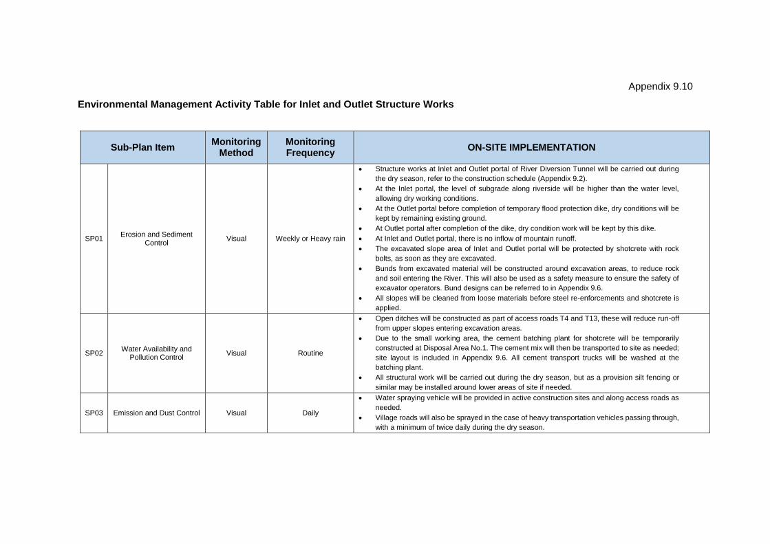
Appendix 9.10
Environmental Management Activity Table for Inlet and Outlet Structure Works
Sub-Plan Item Monitoring
Method Monitoring Frequency
ON-SITE IMPLEMENTATION
SP01 Erosion and Sediment
Control Visual Weekly or Heavy rain
Structure works at Inlet and Outlet portal of River Diversion Tunnel will be carried out during
the dry season, refer to the construction schedule (Appendix 9.2).
At the Inlet portal, the level of subgrade along riverside will be higher than the water level,
allowing dry working conditions.
At the Outlet portal before completion of temporary flood protection dike, dry conditions will be
kept by remaining existing ground.
At Outlet portal after completion of the dike, dry condition work will be kept by this dike.
At Inlet and Outlet portal, there is no inflow of mountain runoff.
The excavated slope area of Inlet and Outlet portal will be protected by shotcrete with rock
bolts, as soon as they are excavated.
Bunds from excavated material will be constructed around excavation areas, to reduce rock
and soil entering the River. This will also be used as a safety measure to ensure the safety of
excavator operators. Bund designs can be referred to in Appendix 9.6.
All slopes will be cleaned from loose materials before steel re-enforcements and shotcrete is
applied.
SP02 Water Availability and
Pollution Control Visual Routine
Open ditches will be constructed as part of access roads T4 and T13, these will reduce run-off
from upper slopes entering excavation areas.
Due to the small working area, the cement batching plant for shotcrete will be temporarily
constructed at Disposal Area No.1. The cement mix will then be transported to site as needed;
site layout is included in Appendix 9.6. All cement transport trucks will be washed at the
batching plant.
All structural work will be carried out during the dry season, but as a provision silt fencing or
similar may be installed around lower areas of site if needed.
SP03 Emission and Dust Control Visual Daily
Water spraying vehicle will be provided in active construction sites and along access roads as
needed.
Village roads will also be sprayed in the case of heavy transportation vehicles passing through,
with a minimum of twice daily during the dry season.
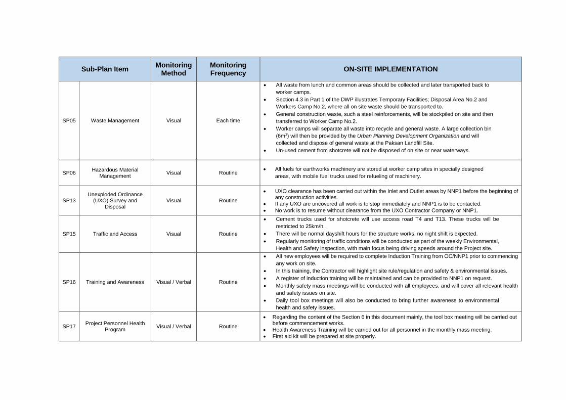
Sub-Plan Item Monitoring
Method Monitoring Frequency
ON-SITE IMPLEMENTATION
SP05 Waste Management Visual Each time
All waste from lunch and common areas should be collected and later transported back to
worker camps.
Section 4.3 in Part 1 of the DWP illustrates Temporary Facilities; Disposal Area No.2 and
Workers Camp No.2, where all on site waste should be transported to.
General construction waste, such a steel reinforcements, will be stockpiled on site and then
transferred to Worker Camp No.2.
Worker camps will separate all waste into recycle and general waste. A large collection bin
(6m3) will then be provided by the Urban Planning Development Organization and will
collected and dispose of general waste at the Paksan Landfill Site. Un-used cement from shotcrete will not be disposed of on site or near waterways.
SP06 Hazardous Material
Management Visual Routine
All fuels for earthworks machinery are stored at worker camp sites in specially designed
areas, with mobile fuel trucks used for refueling of machinery.
SP13 Unexploded Ordinance
(UXO) Survey and Disposal
Visual Routine
UXO clearance has been carried out within the Inlet and Outlet areas by NNP1 before the beginning of any construction activities.
If any UXO are uncovered all work is to stop immediately and NNP1 is to be contacted.
No work is to resume without clearance from the UXO Contractor Company or NNP1.
SP15 Traffic and Access Visual Routine
Cement trucks used for shotcrete will use access road T4 and T13. These trucks will be
restricted to 25km/h.
There will be normal dayshift hours for the structure works, no night shift is expected.
Regularly monitoring of traffic conditions will be conducted as part of the weekly Environmental,
Health and Safety inspection, with main focus being driving speeds around the Project site.
SP16 Training and Awareness Visual / Verbal Routine
All new employees will be required to complete Induction Training from OC/NNP1 prior to commencing
any work on site.
In this training, the Contractor will highlight site rule/regulation and safety & environmental issues.
A register of induction training will be maintained and can be provided to NNP1 on request.
Monthly safety mass meetings will be conducted with all employees, and will cover all relevant health
and safety issues on site.
Daily tool box meetings will also be conducted to bring further awareness to environmental
health and safety issues.
SP17 Project Personnel Health
Program Visual / Verbal Routine
Regarding the content of the Section 6 in this document mainly, the tool box meeting will be carried out before commencement works.
Health Awareness Training will be carried out for all personnel in the monthly mass meeting.
First aid kit will be prepared at site properly.
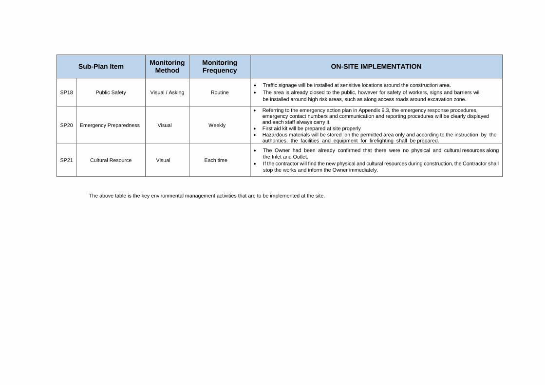
Sub-Plan Item Monitoring
Method Monitoring Frequency
ON-SITE IMPLEMENTATION
SP18 Public Safety Visual / Asking Routine
Traffic signage will be installed at sensitive locations around the construction area.
The area is already closed to the public, however for safety of workers, signs and barriers will
be installed around high risk areas, such as along access roads around excavation zone.
SP20 Emergency Preparedness Visual Weekly
Referring to the emergency action plan in Appendix 9.3, the emergency response procedures, emergency contact numbers and communication and reporting procedures will be clearly displayed and each staff always carry it.
First aid kit will be prepared at site properly
Hazardous materials will be stored on the permitted area only and according to the instruction by the authorities, the facilities and equipment for firefighting shall be prepared.
SP21 Cultural Resource Visual Each time
The Owner had been already confirmed that there were no physical and cultural resources along
the Inlet and Outlet.
If the contractor will find the new physical and cultural resources during construction, the Contractor shall
stop the works and inform the Owner immediately.
The above table is the key environmental management activities that are to be implemented at the site.