no. 51500268 liquisys m cpm 223 / 253 transmitter for ph...
TRANSCRIPT

BA 194C/07/en/07.02No. 51500268Software version 2.50 or later
Liquisys MCPM 223 / 253Transmitter for pH and Redox
Endress HauserThe Power of Know How
Quality made byEndress+Hauser
ISO 9001
ENDRESS+HAUSERLIQUISYS S
ENDRESS+HAUSERLIQUISYS S
Operating Instructions
slp
8.0
deen
220
802

Need information on the instrument?
Please read the following chapters:
Safety
General information
You wish to install the instrument.
The required steps are described in this chapter:
Installation
You wish to operate or reconfigure the instrument.
The operating concept is explained in these chapters:
Operation
Instrument configuration
Interfaces
Need help with problems or maintenance? Please refer
to these chapters:
Diagnosis Maintenance
Appendix
Technical dataAccessories
Index
%Ω°C
PM253E00.CHP
Table of contents
1 General information . . . . . . . . . . . . . . . . . . . . . . . . . . . . . . . . . . . . . . . . . . . . . . . . . . . 21.1 Symbols used . . . . . . . . . . . . . . . . . . . . . . . . . . . . . . . . . . . . . . . . . . . . . . . . . . . . . . . . . . . . . 2
1.2 Storage and transport . . . . . . . . . . . . . . . . . . . . . . . . . . . . . . . . . . . . . . . . . . . . . . . . . . . . . . . 2
1.3 Unpacking . . . . . . . . . . . . . . . . . . . . . . . . . . . . . . . . . . . . . . . . . . . . . . . . . . . . . . . . . . . . . . . . 2
1.4 Dismantling, packaging and disposal . . . . . . . . . . . . . . . . . . . . . . . . . . . . . . . . . . . . . . . . . . . 2
1.5 Product structure . . . . . . . . . . . . . . . . . . . . . . . . . . . . . . . . . . . . . . . . . . . . . . . . . . . . . . . . . . . 3
2 Safety . . . . . . . . . . . . . . . . . . . . . . . . . . . . . . . . . . . . . . . . . . . . . . . . . . . . . . . . . . . . . . . 42.1 Intended application . . . . . . . . . . . . . . . . . . . . . . . . . . . . . . . . . . . . . . . . . . . . . . . . . . . . . . . . 4
2.2 General safety instructions . . . . . . . . . . . . . . . . . . . . . . . . . . . . . . . . . . . . . . . . . . . . . . . . . . . 4
2.3 Installation, start-up, operation . . . . . . . . . . . . . . . . . . . . . . . . . . . . . . . . . . . . . . . . . . . . . . . . 4
2.4 Monitoring and safety features . . . . . . . . . . . . . . . . . . . . . . . . . . . . . . . . . . . . . . . . . . . . . . . . 5
2.5 Immunity to interference . . . . . . . . . . . . . . . . . . . . . . . . . . . . . . . . . . . . . . . . . . . . . . . . . . . . . 5
2.6 Declaration of conformity . . . . . . . . . . . . . . . . . . . . . . . . . . . . . . . . . . . . . . . . . . . . . . . . . . . . . 5
3 Installation. . . . . . . . . . . . . . . . . . . . . . . . . . . . . . . . . . . . . . . . . . . . . . . . . . . . . . . . . . . 63.1 Measuring system . . . . . . . . . . . . . . . . . . . . . . . . . . . . . . . . . . . . . . . . . . . . . . . . . . . . . . . . . . 6
3.2 Dimensions . . . . . . . . . . . . . . . . . . . . . . . . . . . . . . . . . . . . . . . . . . . . . . . . . . . . . . . . . . . . . . . 7
3.3 Mounting . . . . . . . . . . . . . . . . . . . . . . . . . . . . . . . . . . . . . . . . . . . . . . . . . . . . . . . . . . . . . . . . . 8
3.4 Electrical connection . . . . . . . . . . . . . . . . . . . . . . . . . . . . . . . . . . . . . . . . . . . . . . . . . . . . . . . 12
3.5 Electrode installation and measuring cable connection . . . . . . . . . . . . . . . . . . . . . . . . . . . . 14
4 Operation . . . . . . . . . . . . . . . . . . . . . . . . . . . . . . . . . . . . . . . . . . . . . . . . . . . . . . . . . . . 174.1 Operator interface . . . . . . . . . . . . . . . . . . . . . . . . . . . . . . . . . . . . . . . . . . . . . . . . . . . . . . . . . 17
4.2 Display . . . . . . . . . . . . . . . . . . . . . . . . . . . . . . . . . . . . . . . . . . . . . . . . . . . . . . . . . . . . . . . . . . 17
4.3 Keys . . . . . . . . . . . . . . . . . . . . . . . . . . . . . . . . . . . . . . . . . . . . . . . . . . . . . . . . . . . . . . . . . . . . 18
4.4 Auto / manual mode of operation. . . . . . . . . . . . . . . . . . . . . . . . . . . . . . . . . . . . . . . . . . . . . . 19
4.5 Operating concept. . . . . . . . . . . . . . . . . . . . . . . . . . . . . . . . . . . . . . . . . . . . . . . . . . . . . . . . . 20
5 Instrument configuration . . . . . . . . . . . . . . . . . . . . . . . . . . . . . . . . . . . . . . . . . . . . . 235.1 Start-up . . . . . . . . . . . . . . . . . . . . . . . . . . . . . . . . . . . . . . . . . . . . . . . . . . . . . . . . . . . . . . . . . 25
5.2 System configuration . . . . . . . . . . . . . . . . . . . . . . . . . . . . . . . . . . . . . . . . . . . . . . . . . . . . . . . 25
5.3 Current input . . . . . . . . . . . . . . . . . . . . . . . . . . . . . . . . . . . . . . . . . . . . . . . . . . . . . . . . . . . . . 27
5.4 Current outputs . . . . . . . . . . . . . . . . . . . . . . . . . . . . . . . . . . . . . . . . . . . . . . . . . . . . . . . . . . . 30
5.5 Monitoring functions. . . . . . . . . . . . . . . . . . . . . . . . . . . . . . . . . . . . . . . . . . . . . . . . . . . . . . . . 33
5.6 Relay contact configuration . . . . . . . . . . . . . . . . . . . . . . . . . . . . . . . . . . . . . . . . . . . . . . . . . . 38
5.7 Service . . . . . . . . . . . . . . . . . . . . . . . . . . . . . . . . . . . . . . . . . . . . . . . . . . . . . . . . . . . . . . . . . . 50
5.8 E+H Service . . . . . . . . . . . . . . . . . . . . . . . . . . . . . . . . . . . . . . . . . . . . . . . . . . . . . . . . . . . . . . 52
5.9 Interfaces . . . . . . . . . . . . . . . . . . . . . . . . . . . . . . . . . . . . . . . . . . . . . . . . . . . . . . . . . . . . . . . . 52
5.10 Calibration . . . . . . . . . . . . . . . . . . . . . . . . . . . . . . . . . . . . . . . . . . . . . . . . . . . . . . . . . . . . . . . 53
5.11 Offset . . . . . . . . . . . . . . . . . . . . . . . . . . . . . . . . . . . . . . . . . . . . . . . . . . . . . . . . . . . . . . . . . . . 58
6 Interfaces . . . . . . . . . . . . . . . . . . . . . . . . . . . . . . . . . . . . . . . . . . . . . . . . . . . . . . . . . . 59
7 Maintenance and troubleshooting. . . . . . . . . . . . . . . . . . . . . . . . . . . . . . . . . . . . . . 607.1 Troubleshooting common problems . . . . . . . . . . . . . . . . . . . . . . . . . . . . . . . . . . . . . . . . . . . 60
7.2 Troubleshooting using the error messages . . . . . . . . . . . . . . . . . . . . . . . . . . . . . . . . . . . . . . 63
8 Diagnosis and corrective maintenance. . . . . . . . . . . . . . . . . . . . . . . . . . . . . . . . . . 668.1 Diagnosis . . . . . . . . . . . . . . . . . . . . . . . . . . . . . . . . . . . . . . . . . . . . . . . . . . . . . . . . . . . . . . . . 66
8.2 Corrective maintenance of Liquisys M CPM 223. . . . . . . . . . . . . . . . . . . . . . . . . . . . . . . . . . 68
8.3 Corrective maintenance Liquisys M CPM 253. . . . . . . . . . . . . . . . . . . . . . . . . . . . . . . . . . . . 71
8.4 Spare parts orders . . . . . . . . . . . . . . . . . . . . . . . . . . . . . . . . . . . . . . . . . . . . . . . . . . . . . . . . . 74
8.5 Service equipment “Optoscope” with “Scopeware” . . . . . . . . . . . . . . . . . . . . . . . . . . . . . . . 74
8.6 Corrective maintenance of measuring system . . . . . . . . . . . . . . . . . . . . . . . . . . . . . . . . . . . 75
9 Accessories . . . . . . . . . . . . . . . . . . . . . . . . . . . . . . . . . . . . . . . . . . . . . . . . . . . . . . . . . 77
10 Technical data . . . . . . . . . . . . . . . . . . . . . . . . . . . . . . . . . . . . . . . . . . . . . . . . . . . . . . 79
11 Appendix . . . . . . . . . . . . . . . . . . . . . . . . . . . . . . . . . . . . . . . . . . . . . . . . . . . . . . . . . . . 82
12 Index . . . . . . . . . . . . . . . . . . . . . . . . . . . . . . . . . . . . . . . . . . . . . . . . . . . . . . . . . . . . . . . 86
Liquisys M CPM 223 / 253 Table of contents
Endress+Hauser 1

1 General information
1.1 Symbols used
Warning:
This symbol alerts to hazards whichcould cause serious injuries as wellas damage to the equipment ifignored.
Caution:
This symbol alerts to possible faultswhich could arise from incorrectoperation. They could causedamage to the equiment if ignored.
Note:
This symbol indicates importantitems of information.
Double insulation
Equipment protected by doubleinsulation.
Alarm relay
Input
Output
1.2 Storage and transport
The packaging material used to store ortransport the transmitter must provide shockprotection. Optimal protection is provided bythe original packaging materials.
Conformance with the ambient conditions(see Technical data) must be assured.
1.3 Unpacking
Verify that the packaging and the contentsare undamaged! Inform the post office orfreight carrier of any damage.Damaged merchandise must be retained untilthe matter has been settled.
Check that the delivery is complete andagrees with the shipping documents and yourorder (refer to nameplate for type andversion).
Keep the original packaging materials forfuture storage or shipping of the instrument.
If you have any questions, consult yoursupplier or the Endress+Hauser sales agencyin your area (see back cover of theseoperation instructions for addresses).
The delivery includes:
• Transmitter CPM 223 or CPM 253• Operating instructions BA 194C/07/en• Field instrument:
- 1 plug-in screw terminal- 1x cable gland Pg 7- 1x cable gland 16 reduced- 2x cable glands Pg 13.5- 1x NPT adapter set(optional for CSA versions)
• Panel-mounted instrument:- 1 set of plug-in screw terminals- 2 fastening clips- 1 BNC connector (solder-free measuring
cable connection)
1.4 Dismantling, packaging and disposal
Package the assembly properly for reuse at alater point in time. Optimal protection is
provided by the original packaging materials.Observe local regulations for disposal.
General information Liquisys M CPM 223 / 253
2 Endress+Hauser

1.5 Product structure
You can identify the instrument version by the order code on the nameplate.Sub “codes” are the release codes for Software upgrade shown for ChemoClean (left ofdiagonal line) or Plus package (right of diagonal line).
,l
Additional functions of the Plus package (IS / PS version)• Current output table, fields O23x• Monitoring for sensor and process,
function group P
• Neutralisation controller, fields R 26x• Automatic start of cleaning function Field F8
131085-4D
ENDRESS+HAUSERLIQUISYS M
order codeserial no. /codes
pH / RedoxCPM 253-PS1515276944pH 0 … 14 +/-1500 mV-50 … 150°C0/4 … 20 mA230 VAC 50/60 Hz 7.5 VA
-10 … +55°CIP 65
0/4 … 20 mA
- 8732
prot. class ambient temp.
output 1 output 2mains
meas. rangetemperature
Made in GermanyD-70839 Gerlingen
3472
253-TYP.CDR
131085-4D
ENDRESS+HAUSERLIQUISYS M
order codeserial no. /codes
pH / RedoxCPM 223-PR0110276945pH 0 … 14 +/-1500 mV-50 … 150°C0/4 … 20 mA230 VAC 50/60 Hz 7.5 VA
-10 … +55°CIP 54/ IP 30
0/4 … 20 mA
- 87323472
prot. class ambient temp.
output 1 output 2mains
meas. rangetemperature
Made in GermanyD-70839 Gerlingen
223-TYP.CDR Fig. 1.1
left:Nameplate CPM 253
right:Nameplate CPM 223
Liquisys M CPM 223 / 253
VersionIS pH/redox measurement with IsFET or glass electrodePR pH/redox measurement with glass electrodePS pH/redox measurement with glass electrode, with additional functions
(Plus package)
Power supply0 Power supply 230 V AC1 Power supply 115 V AC2 Power supply 230 V AC, CSA Gen. Purp.3 Power supply 115 V AC, CSA Gen. Purp.5 Power supply 100 AC7 Power supply 24 AC, CSA Gen. Purp.8 Power supply 24 V AC/DC
Measurement output0 1 output signal: pH / redox1 2 output signals: pH / redox and temp. / pH or redox / set value3 1 output signal: PROFIBUS-PA4 1 output signal: PROFIBUS-DP5 1 output signal: pH / redox with HART
®
6 2 output signals: pH / redox, HART®
and temperature
Contacts05 No additional contacts10 2 contacts (limit values / PID / timer)15 4 contacts (limit values / PID / timer / ChemoClean)16 4 contacts (limit values / PID / timer)20 2 contacts with current input (limits / PID / timer)25 4 contacts with cleaning, current input
(limit / PID / ChemoClean)26 4 contacts with timer, current input
(limits / PID / timer)
CPM223-complete order code
CPM253-
PM253E01.CHP
Liquisys M CPM 223 / 253 General information
Endress+Hauser 3

2 Safety
2.1 Intended application
The CPM 223/253 transmitter is a field-testedand reliable transmitter used to determine thepH or redox (ORP) value.
The CPM 223/253 is particularly suitable foruse in the following areas of application:
• Chemical industry• Pharmaceutical industry• Foodstuff industry• Drinking water processing• Condensate processing• Municipal sewage treatment plants• Water conditioning• Electroplating
2.2 General safety instructions
This device has been manufactured for safeoperation according to the state of the art inengineering and conforms to the applicableregulations and European standards (seeTechnical data). It has been designedaccording to EN 61010-1 and has left themanufacturer’s works in perfect condition.
However, if used improperly or for purposesother than the intended purpose, it may bedangerous, e.g. due to incorrect connection.
Warning:
• Operating this instrument in anyway other than as described inthese instructions maycompromise the safety andfunction of the measuring systemand is therefore impermissible.
• The notes and warnings in theseinstallation and operatinginstructions must be strictlyadhered to.
2.3 Installation, start-up, operation
Warning:
• This device may only be installed,connected electrically,commissioned, operated andserviced by properly trainedpersonnel authorized by thesystem operator.
• Technical personnel must befamiliar with these operatinginstructions and must adhere tothe instructions described therein.
• Make sure that the power supplyratings match the data specifiedon the nameplate before youconnect the instrument to a powersource.
• A clearly identified mainsdisconnecting device must beinstalled close to the instrument.
• Live components can be touchedthrough the vent slots in thehousing and the openings on therear of the housing. Do not inserttools, wires, etc., in these slots(CPM 223 only).
• Check that all connections havebeen properly made beforepowering up the system!
• Damaged equipment that may bedangerous must not be operatedand should be clearly identified asbeing defective.
• Any troubleshooting of themeasuring system is to beperformed exclusively byauthorized, trained personnel.
• If faults cannot be remedied, theinstrument must be removed fromservice and secured to preventaccidental start-up.
• Repairs not described in theseoperating instructions may only beperformed at the manufacturer’sworks or by the Endress+HauserService Organization.
Safety Liquisys M CPM 223 / 253
4 Endress+Hauser

2.4 Monitoring and safety features
Safety features
The transmitter is protected against externalinfluences and damage by the followingdesign measures:
• Rugged housing• Degree of protection provided by
enclosure: IP 65 (CPM 253)• UV resistance
Monitoring features
In the event of a system error or power failure,an alarm condition is signalled via a fault-signalling contact.
2.5 Immunity to interference
This instrument has been tested according tothe applicable European standards forindustrial applications with regard to electro-magnetic compatibility. It is protected againstelectromagnetic interference by the followingdesign measures:
• Cable screen• Interference suppressor filter• Interference suppression capacitors
Warning:
The specified immunity tointerference only applies for devicesconnected as outlined in theseoperating instructions.
2.6 Declaration of conformity
The CPM 223/253 transmitter has beendeveloped and manufactured in accordancewith currently valid European standards anddirectives.E+H certifies the compliance with the
standards by using the4 sign.
PM253E02.CHP
Liquisys M CPM 223 / 253 Safety
Endress+Hauser 5
3 Installation
The following procedure should be followed for a complete measuring system installation:
• Installation or attachment of transmitter(see chapter 3.3)
• Selection and connection of cable andelectrode (see chapters 3.4, 3.5 and 9)
• Installation is followed by start-up (seechapter 5)
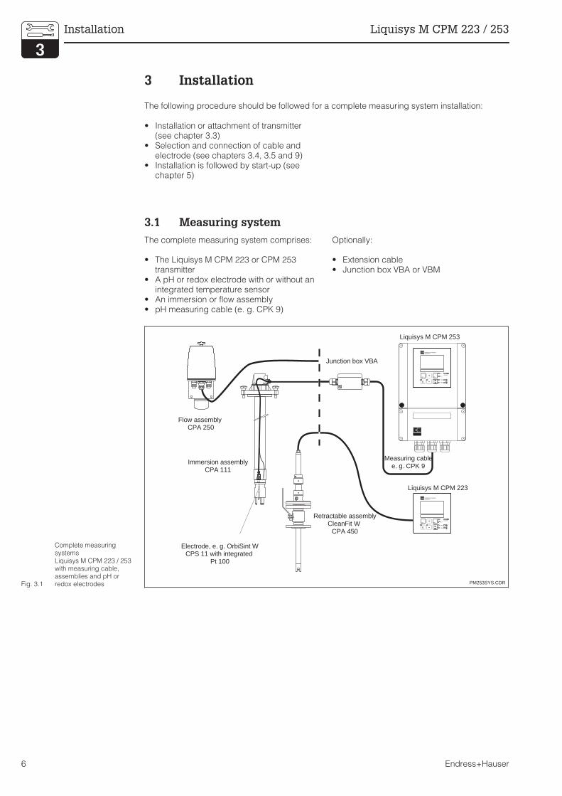
3.1 Measuring system
The complete measuring system comprises:
• The Liquisys M CPM 223 or CPM 253transmitter
• A pH or redox electrode with or without anintegrated temperature sensor
• An immersion or flow assembly• pH measuring cable (e. g. CPK 9)
Optionally:
• Extension cable• Junction box VBA or VBM
ENDRESS+HAUSERLIQUISYS
CAL REL
REL1
REL1
ALARMREL2
REL2E
ENDRESS+HAUSERLIQUISYS
CAL REL
REL1
REL1
ALARMREL2
REL2E
PM253SYS.CDR
Immersion assemblyCPA 111
Flow assemblyCPA 250
Electrode, e. g. OrbiSint WCPS 11 with integrated
Pt 100
Retractable assemblyCleanFit W
CPA 450
Junction box VBA
Liquisys M CPM 253
Measuring cablee. g. CPK 9
Liquisys M CPM 223
Fig. 3.1
Complete measuringsystemsLiquisys M CPM 223 / 253with measuring cable,assemblies and pH orredox electrodes
Installation Liquisys M CPM 223 / 253
6 Endress+Hauser

3.2 Dimensions
Note:
There is a hole in the punching forPg 16 cable entry. It serves as apressure balance during air freightdispatching. Make sure that there isno moisture penetrating into thehousing before cable installation.After cable installation, the housingis completely tight.
ENDRESS+HAUSERLIQUISYS
CAL REL
REL1
REL1
ALARMREL2
REL2E
FELD1.CDR
11
17024
7
115
∅6
157
15470
70
Pg 13.5
Pg 7
Pg 16
Fig. 3.2Dimensions of Liquisys MCPM 253
FELD2.CDR
1
2
3
4
Fig. 3.3
Inside of housing ofLiquisys M CPM 253:1 Removable
electronics box2 Partition plate3 Terminal blocks4 Fuse
PM253E03.CHP
Liquisys M CPM 223 / 253 Installation
Endress+Hauser 7
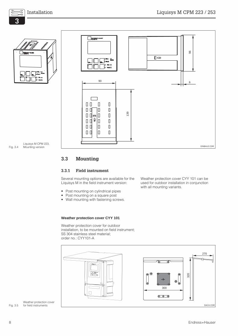
3.3 Mounting
3.3.1 Field instrument
Several mounting options are available for theLiquisys M in the field instrument version:
• Post mounting on cylindrical pipes• Post mounting on a square post• Wall mounting with fastening screws.
Weather protection cover CYY 101 can beused for outdoor installation in conjunctionwith all mounting variants.
Weather protection cover CYY 101
Weather protection cover for outdoorinstallation, to be mounted on field instrument;SS 304 stainless steel material;order no.: CYY101-A
EINBAU2.CDR
96
6
139
90
Fig. 3.4Liquisys M CPM 223,Mounting version
DACH.CDR
300
270
320
Fig. 3.5Weather protection coverfor field instruments
Installation Liquisys M CPM 223 / 253
8 Endress+Hauser

Post mounting kit
Mounting kit for installation of field housing on
horizontal and vertical pipes (max. ∅ 60 mm);material: stainless steel SS 304 (AISI 304);order no. 50086842
Universal mounting post CYY 102
Square tube for mounting of measuringtransmitters; SS 304 material;order no.: CYY102-A
MONT5.CDR
60
90
70
∅ 6
70
70
90
M6
∅8
90
60 x 60
1495
150
120
∅ max. 60
Fig. 3.6
left:Mounting kitfor post mounting oncylindrical pipes
right:Square mounting post
PM253E03.CHP
Liquisys M CPM 223 / 253 Installation
Endress+Hauser 9

3.3.2 Mounting examples
MONT10.CDRFig. 3.7
Pipe mounting ofLiquisys M field instrument
MONT2.CDRFig. 3.8
Liquisys M field instrument
left:Wall mounting
right:Mounting with universalpost and weatherprotection cover
Installation Liquisys M CPM 223 / 253
10 Endress+Hauser
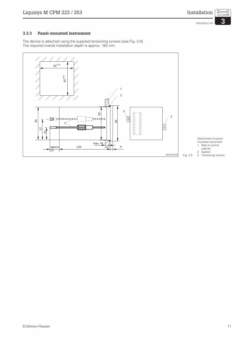
3.3.3 Panel-mounted instrument
The device is attached using the supplied tensioning screws (see Fig. 3.9).The required overall installation depth is approx. 165 mm.
MONT9.CDR
92+0.592
+0,
5
90
57
33
approx.25
max. 45
96
92
1
2
3
139 6
3
3
Fig. 3.9
Attachment of panel-mounted instrument1 Wall of control
cabinet2 Gasket3 Tensioning screws
PM253E03.CHP
Liquisys M CPM 223 / 253 Installation
Endress+Hauser 11

3.4 Electrical connection
Connection diagram
The connection diagram depicted in Fig. 3.10 shows the connections of an instrumentequipped with all the options. The connection of the various electrodes with the measuringcables is shown in more detail in the subsequent figures.
Note:
• The instrument has protectionclass II and is generally operatedwithout protective earthconnection.
• Mains supply voltage fluctuationsshould not exceed ten percent ofthe nominal supply voltage.
• 24V AC/DC models must besupplied from an energy limiting
SELV source in accordance withdir. IEC 1010.1 Annex H.
• Ground the sensor screen in orderto ensure functional safety andmeasuring stability of themeasuring system.Glass electrodes: Terminal “S”.IsFET: PE ground terminal. Theground terminal is located on thecover frame of the panel-mountedinstrument CPM 223 and in theconnection compartment in thefield instrument CPM 253.
pH/SRC
Ref.
11
12
13
47
48
49
57
58
59
51
52
53
54
55
56
PA/PM
15 V85
86
S
10-50 V
81
93
82
94
10-50 V
L+
L-
L1
N
23 +
24 -
mA
∼ =
41
42
43
pH
mA31
32
mA33
34
Aux. voltageoutput
Digitalinput 2(Chemoclean)
Digitalinput 1(Hold)
Signal output 2temperature
Signal output 1pH / redox
Temperature
Electrode Alarm(current-freecontactposition)
Relay 1(current-freecontactposition
Relay 2(current-freecontactposition)
Relay 3(current-freecontactposition)
Relay 4(current-freecontactposition)
Mains
GN
WH
YE
ANPH01.CDR
Ground glass electrodes
Ground IsFET
Current input4...20 mA
Fig. 3.10
Electrical connection ofLiquisys M CPM 223/253with full wiring
Installation Liquisys M CPM 223 / 253
12 Endress+Hauser
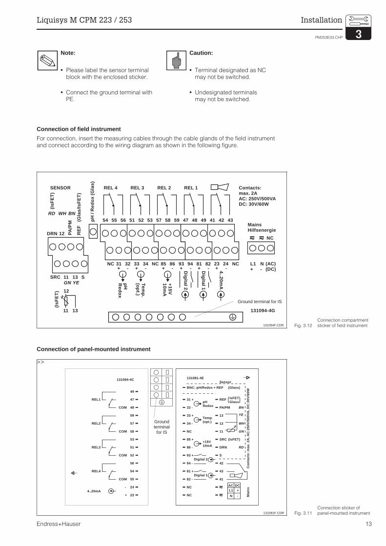
Note:
• Please label the sensor terminalblock with the enclosed sticker.
• Connect the ground terminal withPE.
Caution:
• Terminal designated as NCmay not be switched.
• Undesignated terminalsmay not be switched.
Connection of field instrument
For connection, insert the measuring cables through the cable glands of the field instrumentand connect according to the wiring diagram as shown in the following figure.
Connection of panel-mounted instrument
>>
pH /
Red
ox (
Gla
s)
42
+++++ -----
434154 55 56
NC
SRC
DRN
31
11
12
32
13
PA
/PM
3433
S
RE
F(G
las/
IsF
ET
)
(IsF
ET
)(I
sFE
T)
NC 938685 94 81 82 NC
51 52 53 57 58 59 47 48 49
pHRedox
Temp.
(opt.)
+15V
10mA
YE
WHRD
GN
BN
REL 4SENSOR REL 3 REL 2 REL 1
NC
MainsHilfsenergie
131094-4G
Digital 2
Digital 1
11 13
12
L1+
N-
(AC)(DC)
Contacts:max. 2AAC: 250V/500VADC: 30V/60W
+ -23 24
4..20mA
131094F.CDR
Ground terminal for IS
Fig. 3.12Connection compartmentsticker of field instrument
BNC: pH/Redox + REF
31 +
Sensor
32 -
33 +
34 -
85 +
86 -
93 +
94 - 42
81 + 43
82 - 41
pHRedox
Temp.(opt.)
+15V10mA
Digital 2
Digital 1
NC
NC
NC
131081-4E
S
REF
PA/PM
12
13
11
YE
WH
GN
RD
BN
SRC (IsFET)
(Glass)
IsFETGlass( )
DRN
Mai
nsC
onta
cts:
max
. 2A
, AC
:250
V/5
00V
A, D
C:3
0V/6
0W
L1 +AC DC
N -
REL1
REL2
REL3
REL4
4..20mA24
23
49
COM
COM
COM
COM
-
+
59
54
55
56
52
51
53
58
57
48
47
131084-4C
131081F.CDR
Groundterminal
for IS
Fig. 3.11Connection sticker ofpanel-mounted instrument
PM253E03.CHP
Liquisys M CPM 223 / 253 Installation
Endress+Hauser 13

3.5 Electrode installation and measuring cable connection
Measuring cable connection
The terminal block is located in a separateconnection compartment which is accessibleby opening the plastic cover. Remove thepre-pressed knock-outs for cable entry.
The pH and redox electrodes are connectedusing special terminated and shielded multi-core cables. The measuring cable can beextended with junction box VBA or VBM.Termination instructions are supplied with themeasuring cables.
Note:
• Protect connectors, cable endsand terminals against moisture toprevent inaccurate measurement!
• For futher information on cablesand junction boxes refer to chap.9 Accessories.
Structure and termination of the measuring cable
Measuring cable requirementsSensor type Cable Extension
Electrode without temperature sensor CPK 1 VBA / VBM box + CYK 71 cable
Electrode with temperature sensor Pt 100 andTOP 68 plug-in head
CPK 9 VBA / VBM box + CYK 71 cable
IsFET electrode with temperature sensorPt 100 / Pt 1000 and TOP 68 plug-in head
CPK 12 VBA / VBM box + CYK 12 cable
pH single electrode with reference electrodeand separate temperature sensor
CPK 2 VBA / VBM box+ PMK cable
CPK1_12e.EPSFig. 3.13Construction of specialmeasuring cable
Installation Liquisys M CPM 223 / 253
14 Endress+Hauser
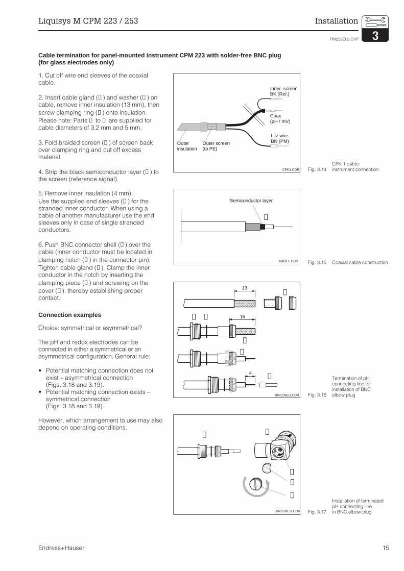
Cable termination for panel-mounted instrument CPM 223 with solder-free BNC plug(for glass electrodes only)
1. Cut off wire end sleeves of the coaxialcable.
2. Insert cable gland (➀ ) and washer (➁ ) oncable, remove inner insulation (13 mm), then
screw clamping ring (➂ ) onto insulation.
Please note: Parts ➀ to ➂ are supplied forcable diameters of 3.2 mm and 5 mm.
3. Fold braided screen (➃ ) of screen backover clamping ring and cut off excessmaterial.
4. Strip the black semiconductor layer (➉ ) tothe screen (reference signal).
5. Remove inner insulation (4 mm).
Use the supplied end sleeves (⑨ ) for thestranded inner conductor. When using acable of another manufacturer use the endsleeves only in case of single strandedconductors.
6. Push BNC connector shell (➄ ) over thecable (inner conductor must be located in
clamping notch (➅ ) in the connector pin).
Tighten cable gland (➀ ). Clamp the innerconductor in the notch by inserting the
clamping piece (➆ ) and screwing on the
cover (➇ ), thereby establishing propercontact.
Connection examples
Choice: symmetrical or asymmetrical?
The pH and redox electrodes can beconnected in either a symmetrical or anasymmetrical configuration. General rule:
• Potential matching connection does notexist – asymmetrical connection(Figs. 3.18 and 3.19).
• Potential matching connection exists –symmetrical connection(Figs. 3.18 and 3.19).
However, which arrangement to use may alsodepend on operating conditions.
CPK1.CDR
Outerinsulation
Outer screen(to PE)
Inner screenBK (Ref.)
Coax(pH / mV)
Litz wireBN (PM)
Fig. 3.14CPK 1 cable:instrument connection
Semiconductor layer
KABEL.CDR
➉
Fig. 3.15 Coaxial cable construction
13
16
4
➁➀
➂
➃
BNC1NEU.CDR
➈
➉
Fig. 3.16
Termination of pHconnecting line forinstallation of BNCelbow plug
⑤➀
➆
➅
➇
BNC2NEU.CDR Fig. 3.17
Installation of terminatedpH connecting linein BNC elbow plug
PM253E03.CHP
Liquisys M CPM 223 / 253 Installation
Endress+Hauser 15

Note:
• The instrument is pre-configuredfor symmetrical measurement.Change the configuration in fieldA2 for asymmetrical measurement(see chapter 5.2.1).
• The conductor for the potentialmatching pin must be connectedto the “PA/PM” terminal of theinstrument for symmetricalmeasurement.
• If the software setting“asymmetrical” is chosen for asymmetrical connection, this willreduce the service life of thereference electrode.
• The instrument is approved forprotection class II and is generallyconnected without protective earth.
• Cable termination is only requiredfor CPM 223.
PH-AN01E.CDRFig. 3.18
pH electrode connectionto Liquisys MCPM 223 / 253
left:Connection of CPS 11with CPK 9
right:Connection of CPS 401with CPK12
RE-AN01E.CDRFig. 3.19
Redox electrodeconnection to Liquisys MCPM 223 / 253
left:Asymmetrical (without PM)
right:Symmetrical (with PM)
Installation Liquisys M CPM 223 / 253
16 Endress+Hauser

4 Operation
4.1 Operator interface
4.2 Display
LED indicators
Liquid crystal display
705pH
R262
Setpoint
ENDRESS+HAUSERLIQUISYS M
DISPLAY1.CDR
Liquid crystal displayfor display of measuredvalues and onfigurationdata
4 main control keys forcalibration and instrumentconfiguration
Key for switchingbetween automatic /manual operation
LED indicators forlimit contactor relay(switching state)
LED indicator foralarm function
Display of activecontact and key forrelay switching inmanual mode
Field for user labelling
Fig. 4.1Operating elementsLiquisys M
Indication of current operating mode “Auto” (green LED) or “Manual” (yellow LED)
Indication for relay controlled “Manual” mode (red LED)
Indicates the state of relays 1 and 2LED green:measured value within permissible limits, relay is inactiveLED red: measured value outside permissible limits, relay is active
Alarm indication e.g. for continuous limit violation, temperature sensor failure or system error(see error list in chapter 7)
05
Setpoint
pH
R262
DISPLAY3.CDR
Measuringmode indicator(normaloperation)
Calibration modeindicator
Setup modeindicator(configuration)
Errorindicator
In measuring mode:Secondary measured value.In setup / calibr. modee.g. setting value
In measuring mode:Main measured value.In setup / calibr. modee.g. parameter
Function coding display
Rel 3/4 stateindicators:
inactive active
“Hold“ mode indicator(current outputs reflectlast status)
For instrument withcommunication:Indicator to receivemessages.Constantly visible inBurst mode (with HART)
Electrode symbol
Temperatureoffset
Manualtemperaturecompensation
Automatictemperaturecompensation
Fig. 4.2 Liquid crystal display
PM253ED4.CHP
Liquisys M CPM 223 / 253 Operation
Endress+Hauser 17

4.3 Keys
CAL keyWhen the CAL key is pressed, the instrument prompts for the calibrationaccess code:
Code 22 for calibration
Code 0 or any code for calibration data checking.Press the CAL key to acknowledge the calibration data or to proceedwithin the calibration menu.
ENTER keyThe ENTER key has serveral functions:
Opens the Setup menu in measuring mode
Stores (acknowledges) data entered in Setup mode
Moving on within the function groups.
PLUS key and MINUS keyThe PLUS and MINUS keys have the following functions:
Selection of function groups
Setting of parameters and numeric values
Relay operation in manual mode (see Ch. 4.4).
Pressing the PLUS key allows you to switch between the current inputin % and mA.
Repeatedly pressing the PLUS key displays the following settings insequence as secondary measured values:1. Temperature display in °F2. Hide temperature display3. Measured value display in mV4. Current input signal in %5. Current input signal in mA6. Back to basic setting
Repeatedly pressing the MINUS key outputs errors:1. The current errors are displayed one after the other (max. 10)2. After all the errors are displayed, the standard display is unhidden.In function group F, you can define an alarm for each error codeseparately.
REL keyThe REL key toggles between the relay and manual cleaning start inmanual mode. In automatic mode you can output the correspondingswitch-on points (limit contactor) ot set points (PID controller) whenpressing the REL key. Pressing the PLUS key allows you to display thesettings of the following relay. Press the REL key to return to measuringmode (automatic return after 30s).
AUTO keyThe AUTO key is used to toggle between the automatic and manualmodes of operation.
Escape functionPress the PLUS and MINUS keys simultaneously to return to the mainmenu. Press the PLUS and MINUS keys again to return to measuringmode.
Locking the keypadPressing the PLUS and ENTER keys simultaneously for minimum 3slocks the keypad against unintentional entries. However, all settings canstill be read. The code prompt displays the code 9999.
Unlocking the keypadPressing the CAL and MINUS keys simultaneously for minimum 3sunlocks the keypad. The code prompt displays the code 0:
Operation Liquisys M CPM 223 / 253
18 Endress+Hauser

4.4 Auto / manual mode of operation
Note:
• Enable the manual mode byentering access code “22”.
• The operating modes remains ineffect even after a power failure.
• The manual mode takesprecedence over any otherautomatic function (hold).
• Hardware locking in the manualmode is not possible.
• The manual settings remain ineffect until they are actively reset.
• Error code E102 is signalled in themanual mode.
Auto modeIn this mode of operation, the relays are controlled by the transmitter.
REL keyIn manual mode, the REL key is used to select one of the relays or thecleaning function present in the instrument.
Switching to manual modeThe instrument is switched to the manual mode for relay setting bypressing the following keys:
Press AUTO key.
Enter code 22. Confirm with ENTER key.
Select relay or function. Press the REL key to toggle between the relays.The display shows the selected relay and the switching status (ON /OFF) in the second line. In manual mode, the measuring value iscontinuously displayed(e.g. for monitoring during dosage).
Set the relays. Switch on with PLUS, switch off with MINUS. The relaystate remains in effect until it is actively reset.
Press AUTO key for returning to the measuring mode.All relais are controlled by the transmitter again.
PM253ED4.CHP
Liquisys M CPM 223 / 253 Operation
Endress+Hauser 19
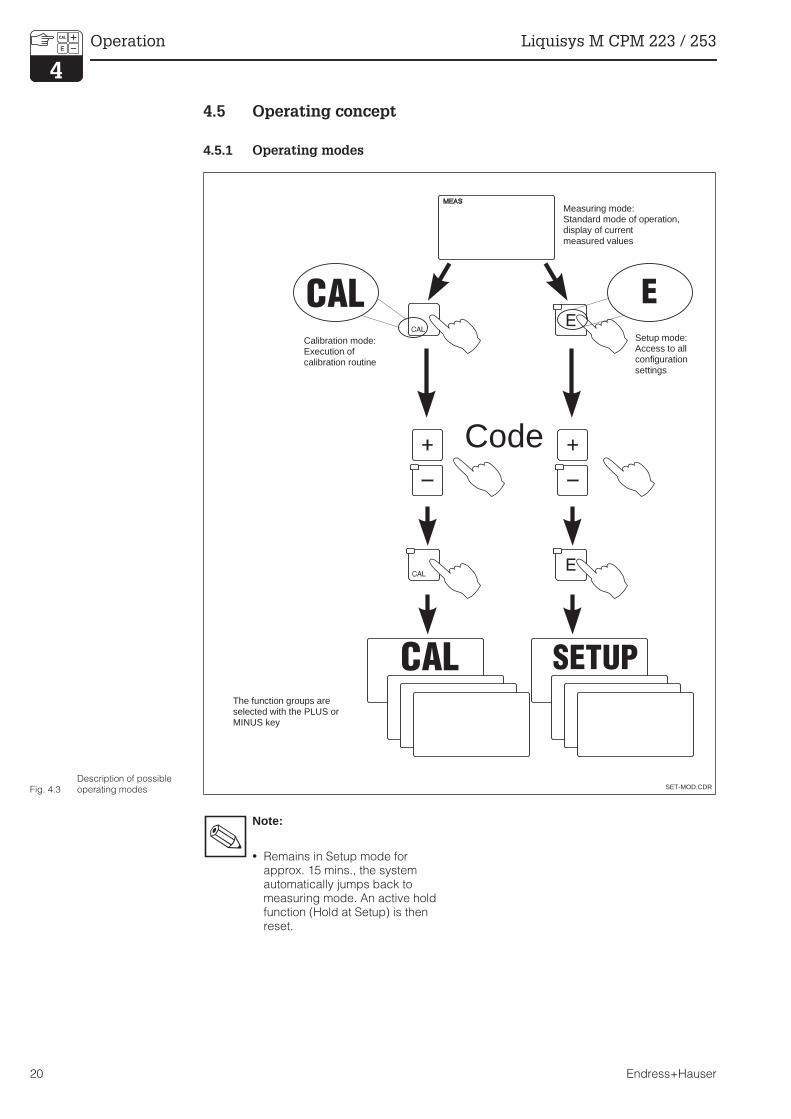
4.5 Operating concept
4.5.1 Operating modes
Note:
• Remains in Setup mode forapprox. 15 mins., the systemautomatically jumps back tomeasuring mode. An active holdfunction (Hold at Setup) is thenreset.
Code
SET-MOD.CDR
Setup mode:Access to allconfigurationsettings
Measuring mode:Standard mode of operation,display of currentmeasured values
The function groups areselected with the PLUS orMINUS key
Calibration mode:Execution ofcalibration routine
Fig. 4.3Description of possibleoperating modes
Operation Liquisys M CPM 223 / 253
20 Endress+Hauser

4.5.2 Access codes
All instrument access codes are fixed, i.e. they cannot be modified. When the instrumentrequests the access codes, it recognises the difference between codes (cf. Fig. 5.3):
• CAL key + Code 22: Access to Calibrationand Offset menus.
• ENTER + Code keys 22: Access to theConfiguration menus, allowing configurati-on and user-specific settings.
• PLUS + ENTER + Code keys 9999:Locks the keypad.
• CAL + MINUS + Code keys 0:Unlocks the keypad.
• CAL or ENTER + Code keys: access toRead mode, i.e. all settings can be readbut not changed.
4.5.3 Menu structure
The configuration and calibration functionsare arranged in a menu structure by functiongroups.
The function groups are selected in the setupmode with the PLUS and MINUS keys. TheENTER key is used to move from one functionto the next within a function group.The PLUS and MINUS keys are used foroption selection and editing. Selections mustbe confirmed by pressing the ENTER key.This also moves the cursor to the nextfunction.Pressing the PLUS and MINUS keys at thesame time terminates programming (return tomain menu).
Note:
• If a change is made but notconfirmed by pressing the ENTERkey, the previous setting isretained.
• See the appendix of theseoperating instructions for anoverview of the Liquisys Mmenu structure.
EE E E
-
BEDSCHE.CDR
Functions(parameter selection, value entry)
Function groupsMove forward and backward with
the PLUS and MINUS keys
Move from one function to thenext with the ENTER key
Fig. 4.4
Schematic representationof Liquisys M menustructure
PM253ED4.CHP
Liquisys M CPM 223 / 253 Operation
Endress+Hauser 21

4.5.4 Hold function: “freezing” of outputsfreezes” the outputs
The current output is “frozen” in the setup mode and during calibration, i.e. the last currentvalue is constantly output. The display shows the “HOLD” message. In case of steady control(4... 20 mA) on current output 2, it is set to 0/4 mA during Hold.
Note:
• Hold settings can be found inchapter 5.5, function S2.
• During automatic operation, allcontacts will go to their normalpositions.
• An active hold has priority over allother automatic functions.
• With every hold, the I componentof the controller is set to zero.
• A possibly accumulated alarmdelay is reset to “0".
• The hold function can also beactivated externally via the holdinput (see wiring diagram inFig. 3.10; digital input 1).
• The manual hold (field S3) remainsactive even after a power failure.
Operation Liquisys M CPM 223 / 253
22 Endress+Hauser
5 Instrument configuration
After power-up the instrument performs aself-test and then enters to measuring mode.
Now it can be configured and calibrated forthe first time. The values set by the user arekept even in the event of a power failure.
The following function groups are available onthe Liquisys M (the function groups that areonly available in the Plus package are markedaccordingly in the functional descriptions):
Setup mode
SETUP 1 (A) see chap. 5.2.1
SETUP 2 (B) see chap. 5.2.2
CURRENT INPUT (Z)see chap. 5.3
CURRENT OUTPUT (O)see chap. 5.4
ALARM (F) see chap. 5.5.1
CHECK (P) see chap. 5.5.2
RELAY (R) see chap. 5.6 SERVICE (S) see chap. 5.7 E+H SERVICE (E) see chap. 5.8 INTERFACE (I) see chap. 5.9
Calibration and Offset mode
CALIBRATION (C) see chap. 5.10.1 NUMERIC (N) see chap. 5.10.2 OFFSET (V) see chap. 5.11
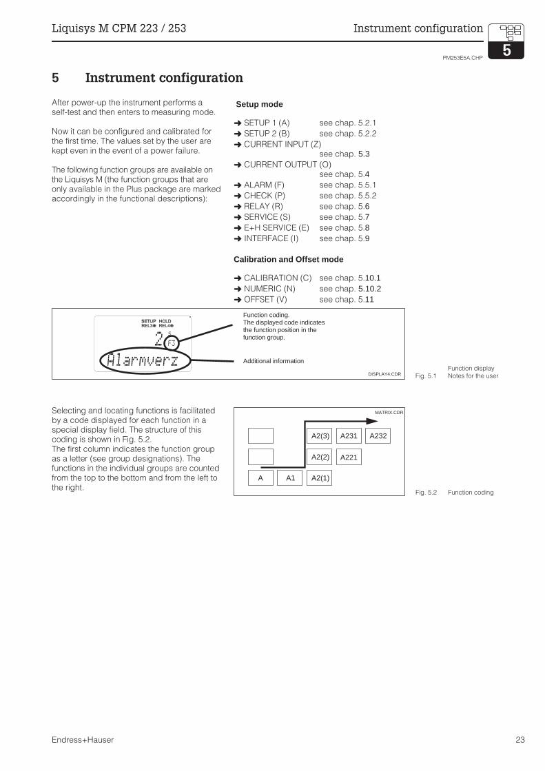
Selecting and locating functions is facilitatedby a code displayed for each function in aspecial display field. The structure of thiscoding is shown in Fig. 5.2.The first column indicates the function groupas a letter (see group designations). Thefunctions in the individual groups are countedfrom the top to the bottom and from the left tothe right.
2s
F3
AlarmverzDISPLAY4.CDR
Function coding.The displayed code indicatesthe function position in thefunction group.
Additional information
Fig. 5.1Function displayNotes for the user
A A1 A2(1)
A2(2)
A2(3) A231
A221
A232
MATRIX.CDR
Fig. 5.2 Function coding
PM253E5A.CHP
Liquisys M CPM 223 / 253 Instrument configuration
Endress+Hauser 23

Factory settings
When the instrument is switched on for the first time, the factory settings are in effect. Thefollowing table provides an overview of all major settings. Please refer to the description of theindividual functions in chapter 5 for all other factory settings (the factory settings are printed in
bold face).
Alarm contact
Normal operating state:
• Instrument in operation• No error message available
(Alarm LED off)
→ Relay picked up
→ Contact 42/43 closed
Alarm state:
• Error message available (Alarm LED red)or
• Instrument defective or voltage-free(Alarm LED off)
→ Relay dropped out
→ Contact 41/42 closed
Function Factory setting
Mode of measurement pH or Redox absolute, Temperature in °C
Type of temperature compensation linear with reference temperature 25.0 °C
Temperature compensation automatic (ATC on)
Limit value for controller 1 pH 16 (redox: –1500 mV or 0 %)
Limit value for controller 2 pH 16 (redox: +1500 mV or 100 %)
Hold active during configuration and calibration
Contact 1 / 3 pH limit contactor, function off
Contact 2 / 4 pH limit contactor, function off
Current outputs 1 and 2* 4 ... 20 mA
Current output 1: measured valuefor 4 mA signal current
pH 2
Current output 1: measured valuefor 20 mA signal current
pH 12
Current output 2: temperaturevalue for 4 mA signal current *
0.0 °C
Current output 2: temperaturevalue for 20 mA signal current*
100.0 °C
* equipped accordingly
RELAY2.CDR
Normal operating state Alarm state
41
42
43
41
42
43
Fig. 5.3Recommended fail-safecircuit for an alarm contact
Instrument configuration Liquisys M CPM 223 / 253
24 Endress+Hauser

5.1 Start-up
After switching the instruement on, make the following settings to the specified function groups:
• Function group SERVICE (S)S1: Select language and exit functiongroup.
• Function group SETUP 1 (A)Adjust all the parameters in this group, seechapter 5.2.1.
• Function group SETUP 2 (B)Make all settings in this group, seechapter 5.2.2.
Other configuration options are explained inthe chapters to follow for each menu.
5.2 System configuration
The system is configured using the function groups SETUP 1 and SETUP 2. The measurementtype and electrode are selected here, and the settings for the temperature measurement aremade. All the parameters in these two function groups are to be configured to avoid measuringerrors or failure to measure at all.
5.2.1 Setup 1 (pH / Redox)
For access to the SETUP menu, please enter Code 22.
Coding Field Selection or rangeFactory setting (bold)
Display Info
AFunction groupSETUP 1
Initial display in function groupSETUP 1.
A1Operating modeselection
pHORP ( = Redox) mVORP ( = Redox) %
Any change in operating modecauses an automatic reset ofbasic settings.
A2 Select display unitpHmV%
A3Select connectionmode
sym = symmetricalasym = asymmetrical
See chapter 3.
A4Enter measuredvalue damping
11 ... 60
Measured value damping causesaveraging over the specifiednumber of individual measuredvalues and is used e. g. tostabilise the display and thesignal output. There is nodamping if “1" is entered.
Factory settings are printed in bold face;base version does not include functions in italic.
A
SETUP 1
pH A1
Oper.Mode
pH A2
Unit
sym A3
wiring
1A3
Damping
PM253E5A.CHP
Liquisys M CPM 223 / 253 Instrument configuration
Endress+Hauser 25
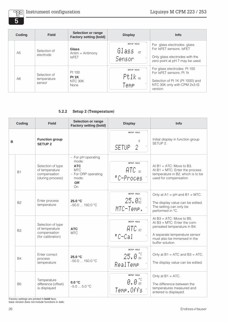
5.2.2 Setup 2 (Temperature)
Coding Field Selection or rangeFactory setting (bold)
Display Info
BFunction groupSETUP 2
Initial display in function groupSETUP 2.
B1
Selection of typeof temperaturecompensation(during process)
– For pH operatingmode:
ATCMTC
– For ORP operatingmode:
OffOn
At B1 = ATC: Move to B3.At B1 = MTC: Enter the processtemperature in B2, which is to beused for compensation.
B2Enter processtemperature
25.0 °C–50.0 ... 150.0 °C
Only at A1 = pH and B1 = MTC.
The display value can be edited.The setting can only beperformed in °C.
B3
Selection of typeof temperaturecompensation(for calibration)
ATCMTC
At B3 = ATC: Move to B5.At B3 = MTC: Enter the com-pensated temperature in B4.
A separate temperature sensormust also be immersed in thebuffer solution.
B4Enter correctprocesstemperature
25.0 °C–50.0 ... 150.0 °C
Only at B1 = ATC and B3 = ATC.
The display value can be edited.
B5Temperaturedifference (offset)is displayed
0.0 °C–5.0 ... 5.0 °C
Only at B1 = ATC.
The difference between thetemperatures measured andentered is displayed.
B
SETUP 2
ATC B1
°C-Proces
25.0B2°C
MTC-Temp.
ATC B3
°C-Cal
25.0°C
B4
RealTemp
0.0°C
B5
Temp.Offs
Coding Field Selection or rangeFactory setting (bold)
Display Info
A5Selection ofelectrode
GlassAntim = AntimonyIsFET
For glass electrodes: glassFor IsFET sensors: IsFET
Only glass electrodes with thezero point at pH 7 may be used.
A6Selection oftemperaturesensor
Pt 100
Pt 1KNTC 30KNone
For glass electrodes: Pt 100For IsFET sensors: Pt 1k
Selection of Pt 1K (Pt 1000) andNTC 30K only with CPM 2x3-ISversion.
Factory settings are printed in bold face;base version does not include functions in italic.
Glass A5
Sensor
Pt1k A6
Temp
Instrument configuration Liquisys M CPM 223 / 253
26 Endress+Hauser

5.3 Current input
This function group offers two independent application solutions, provided that the currentoutput of an external measured quantity, e.g. flow meter, is connected to the 4 … 20 mA inputof Liquisys M CPM 223 / 253. The following assignments then apply:
5.3.1 Monitoring the flow rate in the main stream
This arrangement is highly practical when the sample stream flowing through the flow assembly(e.g. CPA 250) is totally independent of the flow rate in the main stream. This permits thesignalling of an alarm state in the main stream (flow rate too low or totally stopped) and trigger adosing switch-off, even if the measuring water stream is retained due to the installationconfiguration.
Flow in
main stream
Flow alarm
Flow below
switch-off limit Z4
or flow failure
Flow
restored
Alarm relay
Relay contacts
of PID controller
ON
OFF
OFF
OFF
ON
ON
see field Z2 see field Z3
Fig. 5.4
Alarm signalling anddosing switch-off by themain stream
Flow inmain stream
Current signalin mA
Current inputsignal in %
Lower range limitcurrent input
Lower setting valueflow meter
4 0
Upper range limitcurrent input
Upper setting valueflow meter
20 100
PM253E5A.CHP
Liquisys M CPM 223 / 253 Instrument configuration
Endress+Hauser 27

5.3.2 Feedforward control to PID controller
In processes with very short response times it may be practical to apply the flow rate to thecontroller, if the flow rate fluctuates, in order to optimise the control process.
Feedforward control is a multiplying function as depicted in the below figure (factory setting asexample):
ENDRESS+HAUSERLIQUISYS M
CAL REL
REL1
REL1
ALARMREL2
REL2E
mg/l
25.0 °C
0.42
F
4 ... 20 mA
Acid Lye
Static mixer
CPA 250 with
CPS 11
Liquisys M CPM 253
Injection points
Measuring water
extraction point Flow meter
Fig. 5.5
Arrangement example forfeedforward control of theflow rate in the main streamto the PID controller(s)
1
0 20 40 60 80 100Z7
Gain
Kinflu
Current input
signal [%]
1.5
0.5
Fig. 5.6Multiplying feedforwardcontrol
Instrument configuration Liquisys M CPM 223 / 253
28 Endress+Hauser

Coding Field Selection or rangeFactory setting (bold)
Display Info
ZFunction groupCURRENT INPUT
Initial display infunction group
CURRENT INPUT.
Z1
Select flow ratemonitoring of mainstream (withcontrollerswitch-off)
OffInput
Only switch on when flow meteris connected in main stream.
When Z1 = Off, fields Z2 to Z5 donot exist.
Z2
Enter delay forcontrollerswitch-off bycurrent input
0 s0 ... 2000 s
Short-term flow rate undershotscan be suppressed by delay andwill not cause controllerswitch-off.
Z3
Enter delay forcontrollerswitch-on bycurrent input
0 s0 ... 2000 s
With acid / lye monitoring, adelay up until reception of arepresentative measured value ispreferred after a long flow ratefailure.
Z4Enter switch-offthreshold forcurrent input
50%0 ... 100%
0 … 100% corresponds to4 … 20 mA at current input. Notethe measured value allocation tothe current output of the flowmeter.
Z5Select orientationstop for currentinput
LowHigh
If the value entered in Z4 isexceeded low or high, thecontroller switches off.
Z6
Selectfeedforwardcontrol for PIDcontroller
Offlin = linear
When Z6 = Off, Z7 does not exist.
Basic = Feedforward control onlyaffects the basic load(alternatively dosage inproportion to quantity, if commonPID control is not possible, e.g.due to sensor defect)
Z7
Enter value forfeedforwardcontrol at whichmodulation gain= 1
50%0 ... 100%
When the value is set, thecontroller manipulated value withfeedforward control on isidentical to feedforward controloff.
Z
CUR.INPUT
Z2
s
Off Delay
0
Z3
s
On Delay
0
Z4
%
A.Thresh
50
Z5
Stop Dir
Low
Z6
PID influ
Off
Z7
%
Kinflu=1
50
Z1
Cont.stop
Off
PM253E5A.CHP
Liquisys M CPM 223 / 253 Instrument configuration
Endress+Hauser 29

5.4 Current outputs
The function group CURRENT OUTPUT is used to configure the individual outputs. Either alinear (O3 (1)) or, in conjunction with the plus package, a user-defined current outputcharacteristic (O3 (3)) can be entered.Furthermore, a current output value can be simulated to check the current outputs(O3 ( 2)).The controller set value in field R 237 / R 266 can be output via current output 2, if available.
The distance ∆ signal per mA between two table value pairs must exceed:
• pH: 0.03• Redox: 5 mV• Temperature: 0.25 °C
First enter the current output configuration you require in the following blank table. Ensure the
required minimum distance by calculating the resulting signal distance per mA . Then enter theresult in the instrument.
10
8
12
6
0 4 8 12 16 20
pH
Current [mA]∆ current
Fig. 5.7User-defined current outputcharacteristic
Current output 1 Current output 2
Value pairpH / mV /% / °C[ ]
Current[mA]
Distanceper mA
pH / mV /% / °C[ ]
Current[mA]
Distanceper mA
1
2
3
4
5
6
7
8
9
10
Instrument configuration Liquisys M CPM 223 / 253
30 Endress+Hauser

Coding Field Selection or rangeFactory setting (bold)
Display Info
OFunction groupCURRENTOUTPUT
Initial display in function groupCURRENT OUTPUT.
O1Selection ofcurrent output
Out1Out2
A different characteristic can beselected for each output.
O2
Selection ofmeasuringquantity for 2ndcurrent output
°CmVContr
Selection of Curr (= currentoutput 2) in field R237 / R266 isonly possible, if field O2 = Contris selected.
O3 (1)Enter or outputlinearcharacteristic
lin = linear (1)sim = Simulation (2)Tab = Table (3)
The characteristic can have apositive or negative slope at themeasured value output.
At set value output (O2 = Contr),the increasing currentcorresponds to an increasing setvalue.
O311Selection ofcurrent range
4–20 mA0–20 mA
O312
0/4 mA value;entercorresponding pH(redox) ortemperature value
pH 2.00pH –2.00 ... 16.00
–1500 mV–1500 ... 1500 mV
0.0 %0.0 ... 100.0 %
0.0 °C–20.0 ... 150.0 °C
Enter the measured valuecorresponding the the minimumcurrent value (0/4 mA) at thetransmitter output. (Spreadingsee Technical data.)
O313
20 mA value;entercorresponding pH(redox) ortemperature value
pH 12.00pH –2.00 ... 16.00
1500 mV–1500 ... 1500 mV
100.0 %0.0 ... 100.0 %
100.0 °C–20.0 ... 150.0 °C
Enter the measured valuecorresponding to the maximumcurrent value (20 mA) at thetransmitter output. (Spreadingsee Technical data.)
Factory settings are printed in bold face;base version does not include functions in italic.
O
OUTPUT
Out1O1
Sel.Out
O2
Sel. Out2
°C
lin O3
Sel.Type
4-20 O311
Sel.Range
2.00pH
O312
0/4 mA
12.00pH
O313
20 mA
PM253E5A.CHP
Liquisys M CPM 223 / 253 Instrument configuration
Endress+Hauser 31
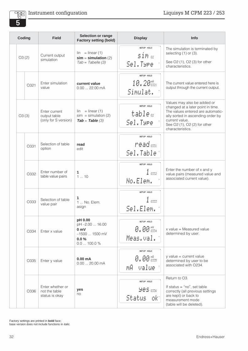
Coding Field Selection or rangeFactory setting (bold)
Display Info
O3 (2)Current outputsimulation
lin = linear (1)
sim = simulation (2)Tab = Tabelle (3)
The simulation is terminated byselecting (1) or (3).
See O2 (1), O2 (3) for othercharacteristics.
O321Enter simulationvalue
current value0.00 ... 22.00 mA
The current value entered here isoutput through the current output.
O3 (3)Enter currentoutput table(only for S version)
lin = linear (1)sim = simulation (2)
Tab = Table (3)
Values may also be added orchanged at a later point in time.The values entered are automatic-ally sorted in ascending order bycurrent value.See O2 (1), O2 (2) for othercharacteristics.
O331Selection of tableoption
readedit
O332Enter number oftable value pairs
11 ... 10
Enter the number of x and yvalue pairs (measured value andassociated current value).
O333Selection of tablevalue pair
11 ... No. Elem.asign
O334 Enter x value
pH 0.00pH –2.00 ... 16.00
0 mV–1500 ... 1500 mV
0.0 %0.0 ... 100.0 %
x value = Measured valuedetermined by user.
O335 Enter y value0.00 mA0.00 ... 20.00 mA
y value = current valuedetermined by user to beassociated with O234.
O336Enter whether ornot the tablestatus is okay
yesno
Return to O3.
If status = “no”, set tablecorrectly (all previous settingsare kept) or back tomeasurement mode(table will be deleted).
Factory settings are printed in bold face;base version does not include functions in italic.
sim O2
Sel.Type
10.20O321mA
Simulat.
O2
Sel.Type
table
O331
Sel.Table
read
O332
No.Elem.
1
O333
Sel.Elem.
1
O334
Meas.val.
0.00pH
O335
mA value
0.00mA
O336
Status ok
yes
Instrument configuration Liquisys M CPM 223 / 253
32 Endress+Hauser
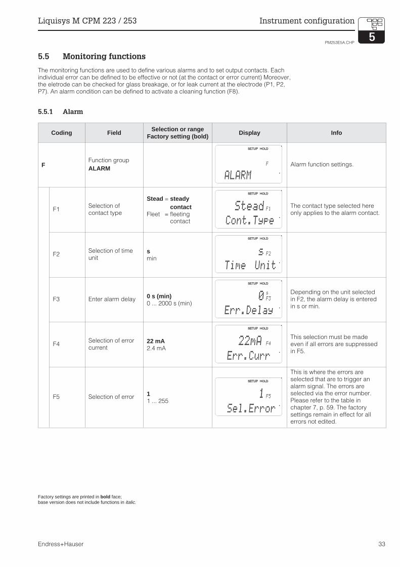
5.5 Monitoring functions
The monitoring functions are used to define various alarms and to set output contacts. Eachindividual error can be defined to be effective or not (at the contact or error current) Moreover,the eletrode can be checked for glass breakage, or for leak current at the electrode (P1, P2,P7). An alarm condition can be defined to activate a cleaning function (F8).
5.5.1 Alarm
Coding Field Selection or rangeFactory setting (bold)
Display Info
FFunction group
ALARMAlarm function settings.
F1Selection ofcontact type
Stead = steadycontact
Fleet = fleetingcontact
The contact type selected hereonly applies to the alarm contact.
F2Selection of timeunit
smin
F3 Enter alarm delay0 s (min)0 ... 2000 s (min)
Depending on the unit selectedin F2, the alarm delay is enteredin s or min.
F4Selection of errorcurrent
22 mA2.4 mA
This selection must be madeeven if all errors are suppressedin F5.
F5 Selection of error11 ... 255
This is where the errors areselected that are to trigger analarm signal. The errors areselected via the error number.Please refer to the table inchapter 7, p. 59. The factorysettings remain in effect for allerrors not edited.
Factory settings are printed in bold face;base version does not include functions in italic.
F
ALARM
F1
Cont.Type
Stead
F2
Time Unit
s
F3
Err.Delay
0s
22mA F4
Err.Curr
F5
Sel.Error
1
PM253E5A.CHP
Liquisys M CPM 223 / 253 Instrument configuration
Endress+Hauser 33
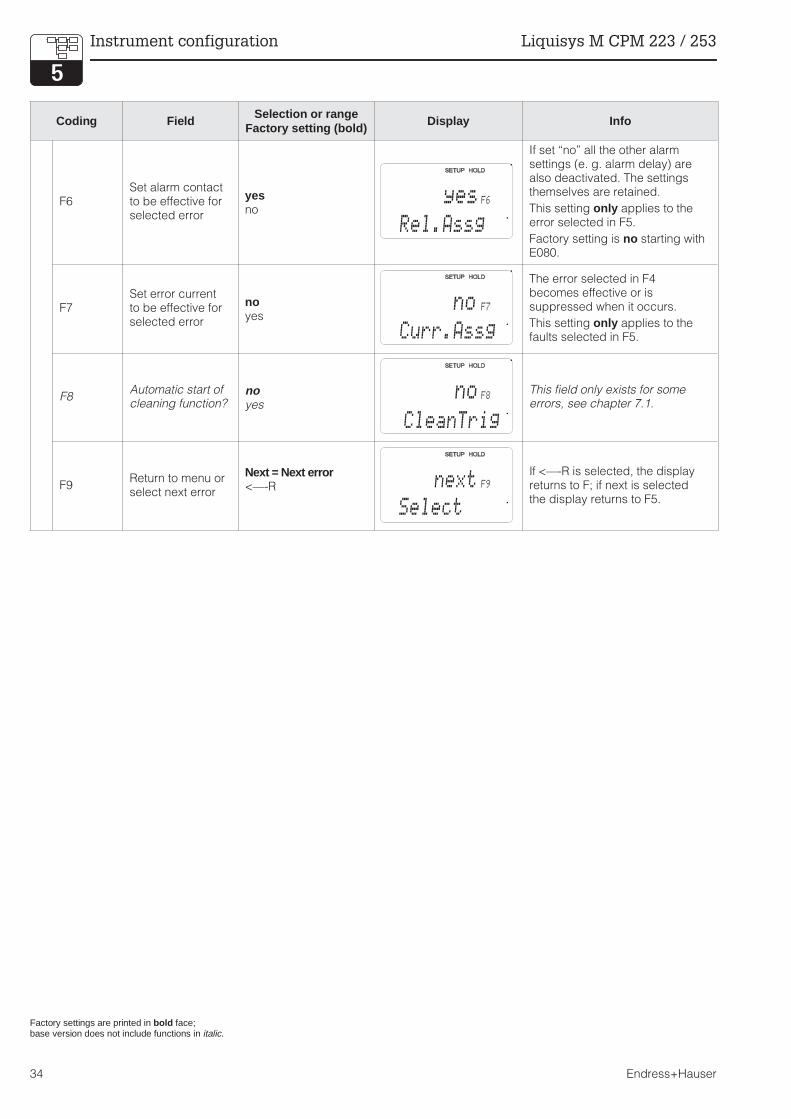
Coding Field Selection or rangeFactory setting (bold)
Display Info
F6Set alarm contactto be effective forselected error
yesno
If set “no” all the other alarmsettings (e. g. alarm delay) arealso deactivated. The settingsthemselves are retained.
This setting only applies to theerror selected in F5.
Factory setting is no starting withE080.
F7Set error currentto be effective forselected error
noyes
The error selected in F4becomes effective or issuppressed when it occurs.
This setting only applies to thefaults selected in F5.
F8Automatic start ofcleaning function?
noyes
This field only exists for someerrors, see chapter 7.1.
F9Return to menu orselect next error
Next = Next error<—-R
If <—-R is selected, the displayreturns to F; if next is selectedthe display returns to F5.
Factory settings are printed in bold face;base version does not include functions in italic.
yes F6
Rel.Assg
no F7
Curr.Assg
no F8
CleanTrig
F9
Select
next
Instrument configuration Liquisys M CPM 223 / 253
34 Endress+Hauser

5.5.2 Check
The function group CHECK is only accessible for instruments equipped with the Plus packet.Two different monitoring functions can be selected for the measurement in the function groupCHECK:
SCS electrode monitoring
The sensor check system monitors the pH and reference electrode for inaccurate measurementand total failure.
The SCS detects:
– Breakage of electrode glass– Fine short circuits in the pH measuring
circuit, e.g. moisture or dirtbridges inclamping points
– Soiling or blocking of reference electrode– Leakage current on IsFET sensor
Three methods are used:
– Monitoring of pH electrode for highresistance (an alarm is signalled when theimpendance drops below a minimum value
of 500 kΩ). This function cannot beselected when using an antimony or IsFETelectrode (A4).
– Monitoring of reference electrodeimpedance (an alarm is signalled when thedefined threshold is exceeded). Thisfunction can only be selected with asymmetrical connection.
– Monitoring of leakage current with IsFETsonsors (pre-alert E168 at ILeak>200 nA,error E008 at ILeak>400 nA).
Caution:
• Do not remove the electrode fromthe process without Hold. Sincethe SCS is measured againstPMC, no contact between theinner conductor and PMC wouldtrigger an alarm.
PCS alarm (Process Check System)
Function AC is used to examine the measuring signal for deviations. If the measuring signal isconstant for a specific period of time (several measured values), an alarm is issued. This typeof behaviour may be caused by soiling, blocking, etc.
Function CC monitors the relay activity. Due to freely selectable monitoring periods for the limitfunctions, a relay failure will be recognised and an alarm will be triggered.
Note:
• Reference electrode monitoring isonly possible in conjunction withthe symmetrical connection (withPMC).
• A current PCS alarm is auto-matically deleted as soon as thesensor signal changes.
• Due to its semiconductorcomponent, the IsFET sensor islight-sensitive and reacts withmeasured value fluctuations. Forthis reason, avoid direct solarradiation during calibration andoperation. Normal ambient lightdoes not affect the measurement.
22 mA
SCS.CDR Fig. 5.8 SCS alarm
Constant measuring signal= alarm is triggered
LIVE.CDR
t
Fig. 5.9 PCS alarm (live-check)
PM253E5A.CHP
Liquisys M CPM 223 / 253 Instrument configuration
Endress+Hauser 35
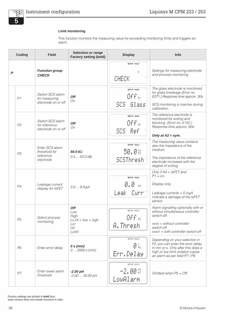
Limit monitoring
This function monitors the measuring value for exceeding monitoring limits and triggers analarm.
Coding FieldSelection or range
Factory setting (bold)Display Info
PFunction groupCHECK
Settings for measuring electrodeand process monitoring
P1Switch SCS alarmfor measuringelectrode on or off
OffOn
The glass electrode is monitoredfor glass breakage (Error no.E071.) Response time approx. 30s.
SCS monitoring is inactive duringcalibration.
P2Switch SCS alarmfor referenceelectrode on or off
OffOn
The reference electrode ismonitored for soiling andblocking. (Error no. E152.)Response time approx. 60s.
Only at A2 = sym.
P3
Enter SCS alarmthreshold forreferenceelectrode
50.0 kΩ0.5 ... 50.0 kΩ
The measuring value containsalso the impedance of themedium.
The impedance of the referenceelectrode increases with thedegree of soiling.
P4Leakage currentdisplay for IsFET 0.0 ... 9.9 µA
Only if A4 = IsFET andP1 = on.
Display only.
Leakage currents > 0.4 µAindicate a damage of the IsFETsensor.
P5Select processmonitoring
OffLowHighLo Hi = low + highLo!Hi!LoHi!
Alarm signalling optionally with orwithout simultaneous controllerswitch-off.
xxxx = without controllerswitch-offxxxx! = with controller switch-off
P6 Enter error delay 0 s (min)0 ... 2000 s (min)
Depending on your selection inF2, you can enter the error delayin min or s. Only after this does ahigh or low limit violation causean alarm as per field P7 / P8.
P7Enter lower alarmthreshold
-2.00 pH-2.00 ... 16.00 pH
Omitted when P5 = Off.
Factory settings are printed in bold face;base version does not include functions in italic.
P
CHECK
Off P1
SCS Glass
Off P2
SCS Ref
P3
k@
SCSThresh
50.0
0.0 P4
Leak Curr
P5
A.Thresh
Off
P6
s
Err.Delay
0
P7
pH
LowAlarm
-2.00
Instrument configuration Liquisys M CPM 223 / 253
36 Endress+Hauser

Coding Field Selection or rangeFactory setting (bold)
Display Info
P8Enter upper alarmthreshold
16.00 pH-2.00 ... 16.00 pH
Omitted when P5 = Off.
P9Select processmonitoring(PCS alarm)
OffACCCAC+CCAC!CC!ACCC!
AC = Sensor alternation check,CC = Controller check.
Alarm signalling optionally with orwithout simultaneous controllerswitch-off.xxxxx = without controllerswitch-off,xxxx! = with controller switch-off.
P10
Enter maximumpermissibleperiod for loweralarm threshold
60 min0 ... 2000 min
Only when P9 = CC or AC+CC.
P11
Enter maximumpermissibleperiod for upperalarm threshold
120 min0 ... 2000 min
Only when P9 = CC or AC+CC.
P12Enter alarmthreshold(for P10 / P11)
1.00 pH-2.00 ... 16.00 pH
Selected value is an absolutevalue. This function is mainlyused for batch process andsingle-sided limit switches.
Factory settings are printed in bold face;base version does not include functions in italic.
P8
pH
HighAlarm
16.00
P9
ProcMonit
Off
P10
min
Tmax Low
60
P11
min
Tmax High
120
P12
pH
Setpoint
1.0
PM253E5A.CHP
Liquisys M CPM 223 / 253 Instrument configuration
Endress+Hauser 37

5.6 Relay contact configuration
The function group RELAYS is only accessible for instruments equipped with the Plus packet.
The relay contacts described below can be selected and configured as required (max. four
contacts depending on options installed):
• Limit contactor for pH / redox value: R2 (1)• Limit contactor for temperature value: R2 (2)• P(ID) controller: R2 (3)• Timer for cleaning function: R2 (4)• ChemoClean function: R2 (5) (for Plus package)• Neutralisation controller: R2 (6) (for Plus package)
5.6.1 Limit contactor for pH/redox measured value and temperature
The relay contacts in the Liquisys M can be
assigned different functions.
Switch-on and switch-off points and pickup
and dropout delays can be defined for the
limit contactor. Moreover, an alarm threshold
can be set to issue an error message and to
start a cleaning function.
These functions may be used for pH/redox
and temperature measurement.
Please refer to Fig. 5.10 for a graphic
representation of the contact states of any
relay or alarm contact.
When the measured value increases (max.
function), the relay contact is closed at time t2when the switch-on point has been exceeded
(t1) and the pickup delay (t2 – t1) has expired.
When the alarm threshold (t3) is reached and
the alarm delay (t4 – t3) also has expired, the
alarm contact is switched.
When the measured value decreases, the
alarm contact is reset when the measured
value drops below the alarm threshold (t5).
The relay contact is also reset (t7, after the
dropout delay t7 - t6 ).
When the pickup and dropout delays are set
to 0 s, the switch-on and switch-off points are
identical to the contact switching points.
Settings analogous to the max function can
also be made for a min function.
t1
t1
t2
t2
t3
t3
t4
t4
t5
t5
t6
t6
t7
t7
t
t
Alarm threshold
Alarm threshold
Switch-on point
Switch-off point
Switch-off point
Switch-on point
Measured valueSwitch-on point > switch-off point: maximum function
Switch-on point < switch-off point: minimum function
Contact ON
Contact ON
Alarm ON
Alarm ON
Alarm OFF
Alarm OFF
Contact OFF
Contact OFF
GRENZ-E.CDRFig. 5.10
Depiction of alarm and
limit functions
Instrument configuration Liquisys M CPM 223 / 253
38 Endress+Hauser

5.6.2 P(ID) controller
The Liquisys M supports the definition of various controller functions. On the basis of the PID
controller, P, PI, PD and PID controllers can be implemented. The best control response is
obtained using the controller best suited to the application in question.Depending on the
selection in field R 237 / R 266, the set value can be output via relay or current output 2.
• P controller: Used for simple linear control purposes with small system deviations. Wheremajor changes are to be controlled, overshooting may occur. A control offset is to beexpected.
• PI controller: Used for processes where overshooting is to be avoided and permanentoffsets are not allowed.
• PD controller: Used for processes that require quick response and where peaks are to becorrected.
• PID controller: Used for processes for which the type of control provided by a P, PI or PDcontroller is inadequate.
Setting options of PID controller
There are three setting options for a PID controller:
• Control gain Kp (P impact)• Integral action time Tn (I impact)• Derivative action time Tv (D impact)
Start-up
If there are no empirical values available for setting the control parameters, use values that
provide the greatest possible stability of the control loop. To optimise the control loop further:
• Increase the control gain Kp until the control variable just starts to overswing.• Decrease Kp again slightly and shorten the integral action time Tn to achieve the shortest
possible correction time without overswing.• In order to shorten the response time of the controller, you also have to set the derivative
action time Tv.
PM253E5B.CHP
Liquisys M CPM 223 / 253 Instrument configuration
Endress+Hauser 39

Control and fine-optimisation of set parameters using a recorder
Actuating signal outputs (R237 ... R2310)
The control contact in question outputs a switched signal. The intensity of this signal is
proportional to the controller’s control output. A distinction is made according to the type of
signal output:
• Pulse length modulationThe greater the calculated control outputthe longer the contact in question remainspicked up. The period can be adjustedbetween 0.5 and 99 s. Pulse length-modulated outputs are used to controlsolenoid valves.
• Pulse frequency modulationThe greater the calculated control output,the higher the switching frequency of thecontact. The maximum switchingfrequency 1/T can be adjusted between 60and 180 min–1. The ON period tON isconstant. Pulse frequency-modulatedoutputs are used to control solenoidoperationed metering pumps.
REGEL02.CDR
Actualvalue
Actual
Actualvalue
Actual
Actual
Tn too smallTn too large
Kp too smallKp too large
Optimal setting
Time
Time
Time
Time
TimeFig. 5.11
Optimisation of settings
Tn and Kp
IMPULS.CDR
tON
tOFF
On
Off
Period length T Time [s]
Contact Contact
tON
T1 T2 Time
On
Off
Fig. 5.12
Signal of a pulse
length-modulated (left)
and a pulse frequency-
modulated (right)
regulating contact
Instrument configuration Liquisys M CPM 223 / 253
40 Endress+Hauser
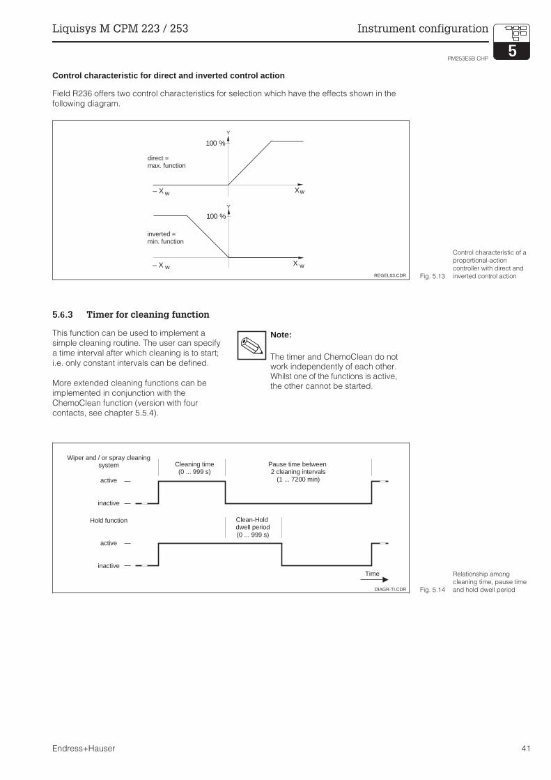
Control characteristic for direct and inverted control action
Field R236 offers two control characteristics for selection which have the effects shown in the
following diagram.
5.6.3 Timer for cleaning function
This function can be used to implement a
simple cleaning routine. The user can specify
a time interval after which cleaning is to start;
i.e. only constant intervals can be defined.
More extended cleaning functions can be
implemented in conjunction with the
ChemoClean function (version with four
contacts, see chapter 5.5.4).
Note:
The timer and ChemoClean do notwork independently of each other.Whilst one of the functions is active,the other cannot be started.
X
X
– X
– X
w
w
w
w
100 %
100 %
Y
Y
direct =max. function
inverted =min. function
REGEL03.CDR Fig. 5.13
Control characteristic of a
proportional-action
controller with direct and
inverted control action
Wiper and / or spray cleaningsystem
active
inactive
Hold function
active
inactive
Cleaning time(0 ... 999 s)
Pause time between2 cleaning intervals
(1 ... 7200 min)
Clean-Holddwell period(0 ... 999 s)
Time
DIAGR-TI.CDR Fig. 5.14
Relationship among
cleaning time, pause time
and hold dwell period
PM253E5B.CHP
Liquisys M CPM 223 / 253 Instrument configuration
Endress+Hauser 41

5.6.4 ChemoClean function
Just like the timer function, ChemoClean can
also be used to start a cleaning cycle.
However, ChemoClean supports different
cleaning and rinse intervals.
Thus, irregular cleaning with different repeat
cycles is possible, and cleaning times with
post-rinse times can be individually defined.
Note:
• Use relays 3 (water) and4 (cleaner) for the ChemoCleanfunction.
• Abortion of the cleaning process isalways followed by a post-rinsetime.
• When “Economy” is selected,cleaning is performed with wateronly.
5.5.5 Neutralisation controller
Note:
Use relays 1 and 2 for theneutralisation control.
Neutralisation control means that the pH value
of a medium is held constant by adding acid
or alkali as required. This task requires two
separate actuating signals – one for acid and
one for alkali.
The neutralisation controller is a controller
with two relay contacts specifically tailored to
this application. A P(ID) controller is available
to handle this task.
The controller gain Kp for acid and alkali can
be separately adjusted. Integral action time Tn
and derivative action time Tv apply to both
controllers (compared to chap. 5.5.2, p. 39).
The “neutral zone” is located between the set-
point 1 and setpoint 2. In the case of a control-
ler without an integral component (P, PD),
there is no alkali or acid dosing ink the “neu-
tral zone” (Y = 0, see Fig. 5.16). In the case of
a controller with an integral component (PI,
PID), there is constant alkali/acid dosing (Ynew
= Yold). The behaviour of the I component
within the “neutral zone” depends on the
process type (Inline / Batch).
The “neutral zone” can be shifted in the X
direction as desired via the set points 1 and 2.
Hold
Water
Cleaner
CHEMO.CDR
t0 t1 t2 t3 t4 t5
t1 cleaning startt2 – t1 pre-rinse timet3 – t2 cleaning timet4 – t3 post-rinse timet5 – t4 hold dwell period
Fig. 5.15 Cleaning cycle sequence
NEUTRA.CDRY [%]
Regulating contact 1for alkali
Regulating contact 2for acid
neutralzone
X
100
50
0Set pointSetpoint 1 Setpoint 2
Fig. 5.16
Characteristic of a
proportionalneutralisation
controller
Instrument configuration Liquisys M CPM 223 / 253
42 Endress+Hauser

Coding Field Selection or rangeFactory setting (bold)
Display Info
RFunction groupRELAIS
Relay contacts can be selectedand adjusted.
R1Selection ofcontact to beconfigured
Rel1Rel2Rel3Rel4
Rel3 (water) and Rel4 (cleaner)are only available on instrumentequipped accordingly. IfChemoClean selected as thecleaning type, Rel4 is notavailable.
R2 (1)
Configuration oflimit contactor forpH / redoxmeasurement
LC PV = pH/redoxlimit contactor (1)LC °C = limitcontactor T (2)PID-controller (3)Timer (4)Clean = ChemoClean (5)Neutra controller (6)
PV = Process valueIf Rel4 is selected in Field R1clean = ChemoClean can not beselected.Confirmation with ENTERswitches off a different, alreadyswitched-on function and itssettings are reset to the default.
R211Switch function ofR2 (1) off or on
offon
All settings are retained.
R212Enter switch-onpoint of thecontact
pH 16.00pH –2.00 ... 16.00
1500 mV–1500 ... 1500 mV
100.0 %0.0 ... 100.0 %
Never set switch-on point andswitch-off point to the same value.(Only the operating modeselected in A1 appears.)
R213Enter switch-offpoint of thecontact
pH 16.00pH –2.00 ... 16.00
1500 mV–1500 ... 1500 mV
100.0 %0.0 ... 100.0 %
The switch-off point entry selectsa max contact (switch-off point< switch-on point) or a mincontact (switch-off point> switch-on point), therebyimplementing an always requiredhysteresis function (see Fig.5.10).
R214 Enter pickup delay0 s0 ... 2000 s
R215Enter dropoutdelay
0 s0 ... 2000 s
Factory settings are printed in bold face;base version does not include functions in italic.
R
RELAY
Rel1 R1
Sel.Relay
LC PV R2
Sel.Type
off R211
Function
16.00pH
R212
On value
16.00pH
R213
Off value
0s
R214
On Delay
0s
R215
Off Delay
PM253E5B.CHP
Liquisys M CPM 223 / 253 Instrument configuration
Endress+Hauser 43
Coding Field Selection or rangeFactory setting (bold)
Display Info
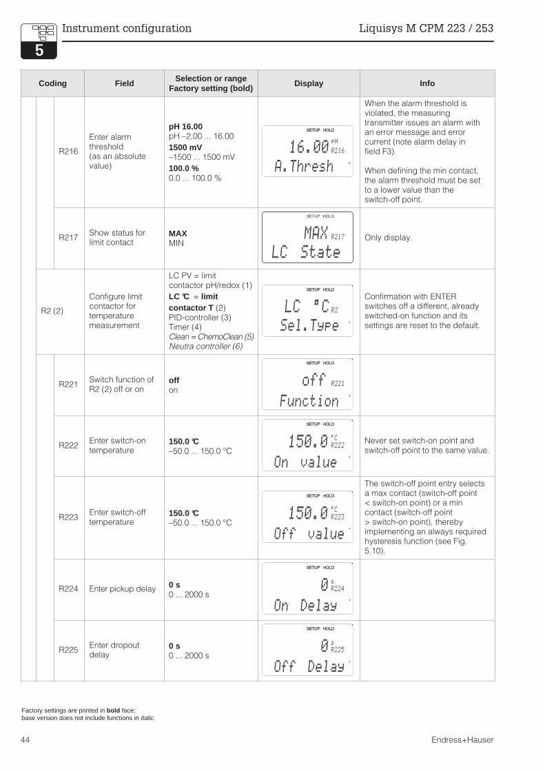
R216
Enter alarmthreshold(as an absolutevalue)
pH 16.00pH –2,00 ... 16.00
1500 mV–1500 ... 1500 mV
100.0 %0.0 ... 100.0 %
When the alarm threshold isviolated, the measuringtransmitter issues an alarm withan error message and errorcurrent (note alarm delay infield F3).
When defining the min contact,the alarm threshold must be setto a lower value than theswitch-off point.
R217Show status forlimit contact
MAXMIN
Only display.
R2 (2)
Configure limitcontactor fortemperaturemeasurement
LC PV = limitcontactor pH/redox (1)
LC °C = limitcontactor T (2)PID-controller (3)Timer (4)Clean = ChemoClean (5)Neutra controller (6)
Confirmation with ENTERswitches off a different, alreadyswitched-on function and itssettings are reset to the default.
R221Switch function ofR2 (2) off or on
offon
R222Enter switch-ontemperature
150.0 °C–50.0 ... 150.0 °C
Never set switch-on point andswitch-off point to the same value.
R223Enter switch-offtemperature
150.0 °C–50.0 ... 150.0 °C
The switch-off point entry selectsa max contact (switch-off point< switch-on point) or a mincontact (switch-off point> switch-on point), therebyimplementing an always requiredhysteresis function (see Fig.5.10).
R224 Enter pickup delay0 s0 ... 2000 s
R225Enter dropoutdelay
0 s0 ... 2000 s
Factory settings are printed in bold face;base version does not include functions in italic.
16.00pH
R216
A.Thresh
R217
LC State
MAX
LC °C R2
Sel.Type
off R221
Function
150.0 R222
°C
On value
150.0 R223
°C
Off value
0 R224
s
On Delay
0 R225
s
Off Delay
Instrument configuration Liquisys M CPM 223 / 253
44 Endress+Hauser

Coding Field Selection or rangeFactory setting (bold)
Display Info
R226
Enter alarmthreshold(as an absolutevalue)
150.0 °C–50.0 ... 150.0 °C
When the alarm threshold isviolated, the measuringtransmitter issues an alarm withan error message and errorcurrent (note alarm delay infield F3).
When defining the min contact,the alarm threshold must be setto a lower value than theswitch-off point.
R227Show status forlimit contact
MAXMIN
Only display.
R2 (3)ConfigureP(ID) controller
LC PV = limitcontactor pH/redox (1)LC °C = limitcontactor T (2)
PID controller (3)Timer (4)Clean = ChemoClean (5)Neutr =Neutra controller (6)
Confirmation with ENTERswitches off a different, alreadyswitched-on function and itssettings are reset to the default.
R231Switch functionR2 (3) off or on
OffOnBasicPID+B
On = PID controlBasic = only basic load dosagePID+B = PID control with basicload dosage
R232 Enter set point
pH 16.00pH –2.00 ... 16.00
1500 mV–1500 ... 1500 mV
0.0 %0.0 ... 100.0 %
The set point is the value to bemaintained by the control. Thisvalue is to be re-established bythe control in the event of anydeviation (up or down).
R233Enter control gainKp
1.000.01 ... 20.00
See chapt. 5.5.2
R234
Enter integralaction time Tn
(0.0 = no Icomponent)
0.0 min0.0 ... 999.9 min
See chap. 5.5.2At every hold the I component isset to zero.Hold can be deactivated in S2,but not for ChemoClean andtimer!
R235
Enter derivativeaction time Tv
(0.0 = no Dcomponent)
0.0 min0.0 ... 999.9 min
See chap. 5.5.2
Factory settings are printed in bold face;base version does not include functions in italic.
150.0 R226°C
A.Thresh
R227
LC State
MAX
PID R2
Sel.Type
off R231
Function
16.00pH
R232
Setpoint
1.00 R233
Kp
0.0 R234
Time Tn
min
0.0 R235
Time TV
min
PM253E5B.CHP
Liquisys M CPM 223 / 253 Instrument configuration
Endress+Hauser 45

Coding Field Selection or rangeFactory setting (bold)
Display Info
R236Selection ofcharacteristiccontroller
dir = directinv = inverted
Setting may or may not berequired depending on controldeviation (up or down deviation,see chap. 5.5.4).
R237Selection of pulselength or pulsefrequency
len = pulse lengthfreq = pulse frequencycurr = current output 2
Pulse length e. g. for solenoidvalve, pulse frequency e. g. forsolenoid-operated meteringpumps, see chap. 5.5.2, S. 40.
Selection of current output 2 is onlypossible, if O2 = Contr is selected
R238 Enter pulse interval10.0 s0.5 ... 999.9 s
This field only appears if pulselength is selected in R237. Whenpulse frequency is selected,R238 is skipped and inputcontinues in R239.
R239Enter maximumpulse frequencyof actuator
120 min –1
60 ... 180 min–1
This field only appears if pulsefrequency is selected in R237.When pulse length is selected,R239 is skipped, and inputcontinues in R2310.
R2310 Enter minimumON time tON
0.3 s0.1 ... 5.0 s
This field only appears if pulselength is selected in R237.
R2311Enter basic load
0%0 ... 40%
Selecting the basic load, youchoose the desired dosagequantity.100% basic load corresponds to:steadily on at R237 = onFmax at R237 = freq20 mA at R237 = curr
R2312Enter process type
BatchInlne
Batch = discontinuous processInlne = continuous process
Selecting “Batch”, there is nofurther dosage within the settingrange. The I component is beingdecreased.Selecting “Inline”, there is aconstant dosage within thesetting range. The I component iseffective.
Factory settings are printed in bold face;base version does not include functions in italic.
dir R236
Direction
len R237
Oper.Mode
10.0 R238
PulsePer.
s
120 R239
Max.PFreq
1/min
0.3 R2310
Min.PTime
s
R2311
%
BasicLoad
0
R2312
%
Proc.Type
Batch
Instrument configuration Liquisys M CPM 223 / 253
46 Endress+Hauser

Coding Field Selection or rangeFactory setting (bold)
Display Info
R2 (4)Configurecleaning function(timer)
LC PV = Limitcontactor pH/redox (1)LC °C = Limitcontactor T (2)PID-controller (3)
Timer (4)Clean = ChemoClean (5)Neutra controller (6)
Cleaning is performed using onlyone cleaning agent (usuallywater); see Fig. 5.14.Confirmation with ENTERswitches off a different, alreadyswitched-on function and itssettings are reset to the default.
R241Switch function ofR2 (4) off or on
offon
R242Enter rinse /cleaning time
30 s0 ... 999 s
The hold and relay settings areactivated for the period of timespecified here.
R243 Enter pause time360 min1 ... 7200 min
The pause time is the timebetween two cleaning cycles(see chap. 5.5.3, S. 41).
R244Enter minimumpause time
120 min1 ... R243 min
The minimum pause timeprevents continuous cleaningwhen the cleaning trigger ispresent.
R2 (5)
Configurecleaning withChemoClean(on version withfour contacts andappropriateassignment ofcontacts 3 and 4)
LC PV = Limitcontactor pH/redox (1)LC °C = Limitcontactor T (2)PID controller (3)Timer (4)
Clean =
ChemoClean (5)Neutra controller (6)
See chap. 5.5.4, p.37.Confirmation with ENTERswitches off a different, alreadyswitched-on function and itssettings are reset to the default.
R251Switch function ofR2 (5) off or on
offon
R252Selection of startpulse
int = internal(timer-contr.)
ext = external(digital input 2)
i+ext = intern. + extern.i+stp = internal,
suppressedby external
The “int” cycle is triggered by theend of the pause time (R257).There is no real-time clock.External suppression is requiredfor irregular time intervals (e.g.weekends).
Factory settings are printed in bold face;base version does not include functions in italic.
Timer R2
Sel.Type
off R241
Function
30 R242
RinseTime
s
360 R243
PauseTime
min
120 R244
Min.Pause
min
Clean R2
Sel.Type
off R251
Function
int R252
CleanTrig
PM253E5B.CHP
Liquisys M CPM 223 / 253 Instrument configuration
Endress+Hauser 47

Coding Field Selection or rangeFactory setting (bold)
Display Info
R253Enter pre-rinsetime
20 s0 ... 999 s
Water is used for rinsing.
R254Enter cleaningtime
10 s0 ... 999 s
Cleaning agent and water areused for cleaning
R255 Enter rinse time20 s0 ... 999 s
Water is used for rinsing.
R256Enter number ofrepeat cycles
00 ... 5
R253 ... R255 is repeated.
R257 Enter pause time360 min1 ... 7200 min
The pause time is the timebetween two cleaning cycles(see Chap. 5.5.3, S. 41).
R258Enter minimumpause time
120 min1 ... R357 min
The minimum pause timeprevents continuous cleaningwhen the cleaning trigger ispresent.
R259
Enter number ofcleaning cycleswithout cleaningagent (economyfunction)
00 ... 9
Cleaning with cleaner can befollowed by up to 9 cleaningcycles that use only water untilthe next cleaning cycle withcleaner is performed.
R2 (6)Configureneutralisationcontroller
LC PV = limit contactorpH/redox (1)LC °C = limitcontactor T (2)PID controller (3)Timer (4)Clean = ChemoClean (5)
Neutra controller (6)
Only if A1 = pH.If the neutralisation controller isselected for Rel1, only the neutracontroller option is offered forRel2.Confirmation with ENTERswitches off a different, alreadyswitched-on function and itssettings are reset to the default.
R261Switch function ofR2 (6) off or on
offon
Factory settings are printed in bold face;base version does not include functions in italic.
R253
PreRinse
20s
10 R254
s
CleanTime
20 R255
s
PostRinse
0 R256
Rep.Rate
360 R257
PauseTime
min
120 R258
Min.Pause
min
0 R259
EconomyCl
Neutr R2
Sel.Type
off R261
Function
Instrument configuration Liquisys M CPM 223 / 253
48 Endress+Hauser

Coding Field Selection or rangeFactory setting (bold)
Display Info
R262Enter setpoint 1(or 2)
pH 6.00pH –2.00 ... 16.00
Assignment of relay 1 and relay 2for neutra controller:Rel 1 = Setpoint 1Rel 2 = Setpoint 2
R263Enter control gainKp1 (or Kp2)
1.000.10 ... 20.00
Assignment of relay 1 and relay 2for neutra controller:Rel 1 = Kp 1Rel 2 = Kp 2
R264Enter integralaction time Tn
(0.0 = no I comp.)
0.0 min0.0 ... 999.9 min
R265Enter derivateaction time Tv
(0.0 = no D comp.)
0.0 min0.0 ... 999.9 min
R266Selection of pulselength or pulsefrequency
len = pulse lengthfreq = pulse frequencycurr = current output 2
Pulse length e. g. for solenoidvalve, pulse frequency e. g. forsolenoid-operated meteringpumps, see chap. 5.5.2, S. 40.
Selection of current output 2 is onlypossible, if O2 = Contr is selected
R267 Enter pulse interval10.0 s0.5 ... 999.9 s
This field only appears if pulselength is selected in R266. Whenpulse frequency is selected,R267 is skipped and inputcontinues in R268.
R268Enter maximumpulse frequencyof actuator
120 min –1
60 ... 180 min–1
This field only appears if pulselength is selected in R266. Whenpulse frequency is selected,R268 is skipped and inputcontinues in R269.
R269Enter minimumON time tON
0.3 s0.1 ... 5.0 s
R2610Enter process type
BatchInlne
Batch = discontinuous processInlne = continuous process
Selecting “Batch”, there is nofurther dosage within the settingrange. The I component is beingdecreased.Selecting “Inline”, there is aconstant dosage within thesetting range. The I component iseffective.
Factory settings are printed in bold face;base version does not include functions in italic.
6.00 R262
pH
Setpoint1
1.00 R263
Kp Rel1
0.0 R264
min
Tn Rel1
0.0 R265
min
TV Rel1
len R266
Oper.Mode
10.0 R267
Puls Per.
s
120 R268
Max.PFreq
1/min
0.3 R269
Min.PTime
s
R2312
%
Proc.Type
Batch
PM253E5B.CHP
Liquisys M CPM 223 / 253 Instrument configuration
Endress+Hauser 49

5.7 Service
Coding Field Selection or rangeFactory setting (bold)
Display Info
SFunction group
SERVICE
S1Selection oflanguage
ENG = EnglishGER = DeutschFRA = FrancaisITA = ItalianoNEL = NederlandsESP = Espanol
This field must be set onceduring start-up. Then you canexit S1 and continue.
S2 Hold configuration
S+C = during setupand calibrating
CAL = duringcalibrating
Setup = duringconfiguring
none = no hold
S = setup,C = calibration.
S3 Manual holdoffon
Setting retains even after a powerfailure.
S4Enter hold dwellperiod
10 s0 ... 999 s
S5
Enter softwareupgrade releasecode (Pluspackage)
00000000 ... 9999
Entering an incorrect codereturns you to the measurementmenu. The number is edited withthe PLUS or MINUS key andconfirmed with the ENTER key.“1" is displayed if the code isactive.
S6
Enter softwareupgraderelease codeChemoClean
00000000 ... 9999
Entering an incorrect codereturns you to the measurementmenu. The number is edited withthe PLUS or MINUS key andconfirmed with the ENTER key.“1" is displayed if the code isactive.
S7Order code isdisplayed
The order code is changedautomatically to reflect anupgrade.
S8Serial number isdisplayed
Factory settings are printed in bold face;base version does not include functions in italic.
S
SERVICE
ENG S1
Language
S+C S2
Auto HOLD
aus S3
Man. HOLD
10 S4
Cont.Time
s
0000 S5
PlusCode
0000 S6
CleanCode
order S7
PR0005
SerNo S8
12345678
Instrument configuration Liquisys M CPM 223 / 253
50 Endress+Hauser

Coding Field Selection or rangeFactory setting (bold)
Display Info
S9
Reset ofinstrument(restore defaultvalues)
noSens = sensor dataFacty= factory
settings
Facty= All data (except A1 and S1)are erased and reset tothe factory settings!
Sens = Last calibration willbe erased and reset to thedefaults.
S10Performinstrument test
nodispl = display test
S11Reference voltageis displayed
current value in mV
Is used for checking thereference potential. Values>50 mV indicate galvanic voltagein the medium. Values >1000 mVmay falsify the measuring value.
S12Select ACfrequency
50 Hz60 Hz
Select 60 Hz only if the voltagefrequency of the measuring pointis 60 Hz and the measuring valuechanges or produces sporadicalSCS errors.
Factory settings are printed in bold face;base version does not include functions in italic.
no S9
S.Default
no S10
Test
25 S11
mV
uncomp Ref
50 S12
Hz
AC Freq
PM253E5B.CHP
Liquisys M CPM 223 / 253 Instrument configuration
Endress+Hauser 51

5.8 E+H Service
5.9 Interfaces
Coding Field Selection or rangeFactory setting (bold)
Display Info
EFunction groupE+H SERVICE
E1Selection ofmodule
Contr = controller (1)Trans = transmitter (2)Main = power unit (3)Rel = relay (4)
E111E121E131E141
Software versionis displayed
Cannot be edited.If E1 = Contr: Instrument softwareIf E1 = Trans, Main, Rel: Modulefirmware
E112E122E132E142
Hardware versionis displayed
Cannot be edited.
E113E123E133E143
Serial number isdisplayed
Cannot be edited.
E114E124E134E144
Module name isdisplayed
Cannot be edited.
Coding FieldSelection or range
Factory settingDisplay Info
IFunction groupINTERFACE
I1 Enter address
Address
HART: 0 ... 15or
PROFIBUS: 1 ... 126
Only for communication.
E
E+H SERV
Contr E1
Select
xx.xx E111
SW-Vers.
xx.xx E112
HW-Vers.
SerNo E113
12345678
LSG E114
Modul-ID
I
INTERFACE
126 I1
Address
Instrument configuration Liquisys M CPM 223 / 253
52 Endress+Hauser

5.10 Calibration
This function group is used to calibrate the
transmitter. Two types of calibration are
possible:
• Calibration by means of measurement intwo calibration solutions with a known pHvalue.
• Calibration by entering daa for slope andzero point
• For redox measurement by entering themV value or two different % values.
Note:
• If the calibration procedure isaborted by pressing the PLUS andMINUS keys at the same time(return to C19, C25 or C36) or ifthe calibration is faulty, then theprevious calibration data isreinstated. A calibration error isindicated by the “ERR” messageand flashing of the sensor symbolon the display.Repeat the calibration!
• The instrument is automaticallyswitched to hold during calibration(factory setting).
• An offset entered by the user isautomatically cancelled when thecalibration is accepted.
• If the slope or zero point is outsidethe ranges defined in C16 andC17, error 32 is activated for slopeor error 33 for zero. The electrodeshould be then checked andreplaced if necessary.
Coding Field Selection or rangeFactory setting
Display Info
I2 Tag description Only for communication.I2
@@@@@@@@
Tag
PM253E5B.CHP
Liquisys M CPM 223 / 253 Instrument configuration
Endress+Hauser 53
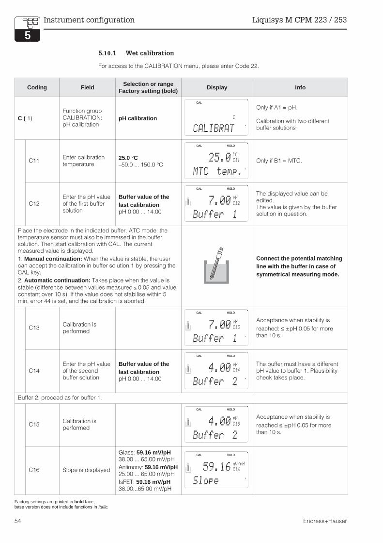
5.10.1 Wet calibration
For access to the CALIBRATION menu, please enter Code 22.
Coding Field Selection or rangeFactory setting (bold)
Display Info
C ( 1)
Function groupCALIBRATION:pH calibration
pH calibration
Only if A1 = pH.
Calibration with two differentbuffer solutions
C11Enter calibrationtemperature
25.0 °C–50.0 ... 150.0 °C
Only if B1 = MTC.
C12Enter the pH valueof the first buffersolution
Buffer value of thelast calibrationpH 0.00 ... 14.00
The displayed value can beedited.The value is given by the buffersolution in question.
Place the electrode in the indicated buffer. ATC mode: thetemperature sensor must also be immersed in the buffersolution. Then start calibration with CAL. The currentmeasured value is displayed.
1. Manual continuation: When the value is stable, the usercan accept the calibration in buffer solution 1 by pressing theCAL key.
2. Automatic continuation: Takes place when the value is
stable (difference between values measured ≤ 0.05 and valueconstant over 10 s). If the value does not stabilise within 5min, error 44 is set, and the calibration is aborted.
Connect the potential matchingline with the buffer in case ofsymmetrical measuring mode.
C13Calibration isperformed
Acceptance when stability is
reached: ≤ ±pH 0.05 for morethan 10 s.
C14Enter the pH valueof the secondbuffer solution
Buffer value of thelast calibrationpH 0.00 ... 14.00
The buffer must have a differentpH value to buffer 1. Plausibilitycheck takes place.
Buffer 2: proceed as for buffer 1.
C15Calibration isperformed
Acceptance when stability is
reached ≤ ±pH 0.05 for morethan 10 s.
C16 Slope is displayed
Glass: 59.16 mV/pH38.00 ... 65.00 mV/pH
Antimony: 59.16 mV/pH25.00 ... 65.00 mV/pH
IsFET: 59.16 mV/pH38.00...65.00 mV/pH
Factory settings are printed in bold face;base version does not include functions in italic.
C
CALIBRAT
25.0 C11
MTC temp.
°C
7.00 C12
Buffer 1
pH
7.00 C13
Buffer 1
pH
4.00 C14
Buffer 2
pH
4.00 C15
Buffer 2
pH
59.16 C16
Slope
mV/pH
Instrument configuration Liquisys M CPM 223 / 253
54 Endress+Hauser
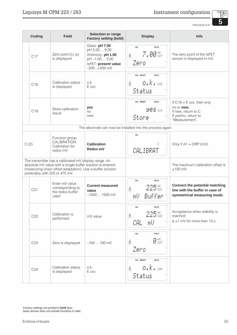
Coding Field Selection or rangeFactory setting (bold)
Display Info
C17Zero point (U_is)is displayed
Glass: pH 7.00pH 5.00 ... 9.00
Antimony: pH 1.00pH –1.00 ... 3.00
IsFET: present value–500...+500 mV
The zero point of the IsFETsensor is displayed in mV.
C18Calibration statusis displayed
o.k.E xxx
C19Store calibrationresult
yesnonew
If C18 = E xxx, then only
no or new.If new, return to C.If yes/no, return to“Measurement”.
The electrode can now be installed into the process again.
C (2)
Function groupCALIBRATION:Calibration forredox mV
CalibrationRedox mV
Only if A1 = ORP (mV).
The transmitter has a calibrated mV display range. Anabsolute mV value with a single buffer solution is entered(measuring chain offset adaptation). Use a buffer solutionpreferably with 225 or 475 mV.
The maximum calibration offset is±100 mV.
C21
Enter mV valuecorresponding tothe redox bufferused
Current measuredvalue–1500 ... 1500 mV
Connect the potential matchingline with the buffer in case ofsymmetrical measuring mode.
C22Calibration isperformed
mV value
Acceptance when stability isreached
≤ ±1 mV for more than 10 s.
C23 Zero is displayed –100 ... 100 mV
C24Calibration statusis displayed
o.k.E xxx
Factory settings are printed in bold face;base version does not include functions in italic.
7.00 C17
Zero
pH
o.k. C18
Status
yes C19
Store
C
CALIBRAT
225 C21
mV Buffer
mV
225 C22
CAL mV
mV
0 C23
Zero
mV
o.k. C24
Status
PM253E5B.CHP
Liquisys M CPM 223 / 253 Instrument configuration
Endress+Hauser 55

Coding Field Selection or rangeFactory setting (bold)
Display Info
C25Store calibrationresult?
yesnonew
If C24 = E xxx, then only
no or new.If new, return to C.If yes/no, return to“Measurement”.
The electrode can now be installed into the process again.
C (3)
Function groupCALIBRATION:Calibration forredox %
CalibrationRedox %
Only at A1 = ORP (%).
For calibration, a medium sample is drawn and place in twobuckets. The contents of the first bucket are detoxicated. Thecontents of the second bucket remains unchanged. A relativevalue of 80 % is enterd for the “toxic” sample. The “non-toxic”sample is used for a relative value 20 %.
Default values:0 % = –1000 mV100 % = +1000 mV
C31Determine 80%value of the“toxic” sample
80%0 ... 100%
Start the calibration with the“toxic” sample by pressing theCAL key. The value is accepted,as soon as it is stable or isconfirmed with the CAL key (seepH calibration).
C32Calibration isperformed
mV value is displayed
Acceptance when stability is
reached: ≤ ±pH 0.05 for morethan 10 s.
C33Determine 20 %value of “non-toxic” sample
80%0 ... 100%
The procedure started in C31 isrepeated with the “non-toxic”sample to calibrate value 2.
C34Calibration isperformed
mV value is displayed
Acceptance when stability is
reached: ≤ ±pH 0.05 for morethan 10 s.
C35Calibration statusis displayed
o.k.E xxx
C36Store calibrationresult
yesnonew
If C35 = E xxx, then only
no or new.If new, return to C.If yes/no, return to“Measurement”.
The electrode can now be installed into the process again.
Factory settings are printed in bold face;base version does not include functions in italic.
yes C25
Store
C
CALIBRAT
80 C31
Sample 1
%
200 C32
CAL 80%
mV
20 C33
Sample 2
%
50 C34
CAL 20%
mV
o.k. C35
Status
yes C36
Store
Instrument configuration Liquisys M CPM 223 / 253
56 Endress+Hauser

5.10.2 Numeric calibration
With the numeric calibration you can enter or correct slope and zero point manually.
Coding Field Selection or rangeFactory setting (bold)
Display Info
NFunktionsgruppeNUMERICCALIBRATION
N1Enter referencetemperature
25 °C-50.0 ... 150.0 °C
N2 Enter slope
Glass 59.18 mV/pH38.00 ... 65.00 mV/pH
Antimony 59.18 mV/pH25.00 ... 65.00 mV/pH
IsFET 59.18 mV/pH38.00 ... 65.00 mV/pH
If A5 = IsFET: Enter slope from
quality certificate
N3 Enter zero point
Glass 7.00 pH5.00 ... 9.00 pH
Antimony 1.00 pH-1.00 ... 3.00 pH
IsFET 0 mV-500 ... + 500 mV
If A5 = IsFET: Enter voltage UIS
from quality certificate
N4Calibration statusis displayed
o.k.E-
N
NUMERIC
25°C N1
T°C Ref
59.18 N2
mv/pH
Slope
7.00 N3
pH
Zero
o.k. N4
pH
Status
Factory settings are printed in bold face;base version does not include functions in italic.
PM253E5B.CHP
Liquisys M CPM 223 / 253 Instrument configuration
Endress+Hauser 57

5.11 Offset
The settings in the OFFSET function group can be used to calibrate the measurement to a reference
measurement. This requires a linear shift of all values measured, i.e. the adjustment is determined
for one measured value, and all others are calculated using the same offset.
Note:
The offset is automatically reset tozero after calibration.
OFFSET.CDR
Mea
sure
dva
lue
Time t
Current measured value
Calibrated value
Fig. 5.17 Offset
Coding Field Selection or rangeFactory setting (bold)
Display Info
VFunction groupOFFSETfor pH or redox
Either pH or redox appearsdepending on the operatingmode in A1.
V1Enter desiredvalue
Current measuredvaluepH –2.00 ... 16.00–1500 ... 1500 mV0.0 ... 100.0 %
Display can be edited.
V2Current offset isdisplayed
pH 0.00pH –2.00 ... 2.00
0 mV–120 ... 120 mV
0.0 %–50.0 ... 50.0 %
V3Calibration statusis displayed
o.k.E xxx
V4Store calibrationresult
yesnonew
If V3 = E xxx, then only
no or new.If new, return to V.If yes/no, return to“Measurement”.
Factory settings are printed in bold face;base version does not includde functions in italic.
V
OFFSET
V1
pH
Real PV
0.00
V2
pH
PV Offset
0.00
o.k. V3
Status
yes V4
Store
Instrument configuration Liquisys M CPM 223 / 253
58 Endress+Hauser

6 Interfaces
For instruments equipped with a communication interface, please refer to separate operatinginstructions BA 208C/07/en (HART
®) or BA 209C/07/en (PROFIBUS
®).
PM253E06.CHP
Liquisys M CPM 223 / 253 Interfaces
Endress+Hauser 59

7 Maintenance and troubleshooting
Maintenance:
• Maintenance means that all measures which will guarantee the safety of operation andreliability of the entire measuring system are taken in due time.
Maintenance of CPM 223 / 253 includes:• Calibration (see chapter 5.9)• Cleaning of assembly and sensor• Checking of cables and connections
Troubleshooting:
Determination and elimination of the cause of the problem in the case of an operating fault.Troubleshooting refers to measures that can be performed without intervention in the instrument(for instrument defects, see chapter 8, Corrective maintenance).
Troubleshooting of the CPM 223/253 and the measuring system is performed with the aid of thetroubleshooting table in chapter 7.1.
Warning:
• Please be aware of effects workperformed on the instrument mighthave on the process controlsystem or the process itself.
• When removing the sensor duringmaintenance or calibration, pleaseconsider potential hazards due topressure, high temperatures andcontamination.
Note:
• Please contact your E+H supportoffice if you have any queries. Youcan also send your queries to theE+H Service Organisation via theInternet.
www.endress.com
7.1 Troubleshooting common problems
Error Possible cause Remedy Equipment need, spare parts
Device cannot be
operated, value 9999
– Operation locked Press simultaneously the CAL and
MINUS keys
See chap. 4.3
Measuring chain not
adjustable
– Reference system poisened Test with new Sensor pH/mV sensor
– Diaphragma clogged Clean or grind down diaphragma HCl 3 %, use file (only file in one
direction)
– Measuring line open Short-circuit pH input on
instrument ⇒ display pH 7
– Sensor asymmetry voltage too
high
Clean diaphragma test with other
sensor
HCl 3 %, use file (only file in one
direction)
– Potential matching (PA/PM)
Liquisys ⇔ wrong medium
asymm.: no PA or PA conn. to PE
symm.: PA connection mandatory
See chap. 3.5
No or creeping change
of display
– Sensor soiled Clean sensor See chap. 8.6.2
– Sensor ageing Replace sensor new sensor
– Sensor defective (ref. electrode) Replace sensor new Sensor
– No internal buffer Check KCl supply
(0.8 bar above medium pressure!)
KCl (CPY 4-x)
Measuring chain slope /
slope too low
– No high-resistance connection
(moisture, dirt)
Check cables, connectors and
junction boxes
pH simulator,
Insulation see chap. 8.6.5
– Instrument input defective Check instrument directly pH simulator
– Sensor ageing Replace sensor pH sensor
Measuring chain slope
not adjustable / no slope
– Hair crack in glass membrane Replace sensor pH sensor
– No high-resistance connection
(moisture, dirt)
Check cables, connectors and
junction boxes
pH simulator,
insulation see chap. 8.6.5
Maintenance and troubleshooting Liquisys M CPM 223 / 253
60 Endress+Hauser

Error Possible cause Remedy Equipment need, spare parts
Fixed, incorrect
measure value
– Sensor not immersed or
protective cap not removed
Check installation, remove
protective cap
– Air cushion in assembly Check assembly and installation
– Short to ground on/in instrument Test measurement in insulated
container, poss. with buffer solution
Plastic container, buffer solutions
– Hair crack in glass membrane Replace sensor pH sensor
– Impermissible instrument
operating state (no response to
key actuation)
Switch instrument off and back on EMV problem: check grounding
and line routing if problem persists
Incorrect temperature
value
– Incorrect sensor connection Verify connections using
connection diagram
Connection diagram chap. 3.4
– Measuring cable defective Check cable Ohmmeter
– Incorrect sensor type Select sensor type on instrument
(field B1)
Glass electrode: Pt 100
IsFET: Pt 1000
Incorrect pH value in
process
– No / incorrect temperature
compensation
ATC: activate function
MTC: set process temperature
– Conductivity of medium too low Choose pH sensor with salt
reservoir or liquid KCI
e.g. Orbisint CPS 11-xASxxxx
e.g. Ceraliquid CPS 41
– Flow rate too high Reduce flow rate or measure in a
bypass
– Potential in medium Try grounding with/at PA pin
(PA/PE connection)
Problem mainly occurs with plastic
lines
– Sensor soiled or coated Clean sensor (see chap. 8.6.2) Heavily soiled media: use spray
cleaning
Measured value
fluctuates
– Measuring cable interference Connect cable screen acc. to
connection diagram
See chap. 3.5
– Signal output line interference Check line routing, try separate
line routing
Signal output and meas. input lines
– Interference potential in medium Use symmetric measurement (with
PMC)
Try grounding medium via PA/PE
connection
– No potential matching (PA/PM)
with symmetrical input
Connect PA pin in assembly to
PA/PM on instrument
Controller or timer
cannot be activated
– No relay module installed Install LSR1-2 or LSR1-4 module See chap. 8.2 and 8.3
Controller / limit contact
does not work
– Controller switched off Activate controller See chap. 5.5 or fields R2xx
– Controller in “Manual / Off” mode Choose “Auto” or “Manual On”
mode
Keyboard, REL key
– Pickup delay setting too long Disable or shorten pickup delay See fields R2xx
– “Hold” function active “Autom. hold” during calibration,
“hold”-input activated;
“hold” via keyboard active
See fields S2 to S4
Controller / limit contact
works continuously
– Controller in “Manual / On” mode Set controller to “Manual / Off” or
“Auto”
Keyboard, REL and AUTO keys
– Dropout delay setting to long Shorten dropout delay See fields R2xx
– Control loop interruption Check measured value, current
output or relay contacts, actuators,
chemical supply
No pH/mV current
output signal
– Line open or short-circuit Disconnect line and measure
directly in instrument
mA meter 0–20 mA DC
– Output defective See chap. 8.1
Fixed current output
signal
– Currenct simulation active Switch-off simulation See field O2
– Processor system out of sync Switch instrument off and back on EMV problem: Check installation if
problem persists
Incorrect current output
signal
– Incorrect current assignment Check current assignment:
0–20 mA or 4–20 mA?
Field O211
– Total load in current loop
excessive (> 500 Ω)
Disconnect output and measure
directly on instrument
mA meter for 0–20 mA DC
Current output table not
accepted
– Value interval too small Use sensible intervals
PM253E07.CHP
Liquisys M CPM 223 / 253 Maintenance and troubleshooting
Endress+Hauser 61

Error Possible cause Remedy Equipment need, spare parts
No temperature output
signal
– Instrument only has one current
output
Refer to nameplate for variant,
change LSCH-x1 module if nec.
LSCH-x2 module,
see chap. 8.2.4 and 8.3.4
– Instrument with Profibus PA PA instrument has no current output!
Chemoclean function
not available
– No relay module (LSR1-x) or only
LSR1-2 installed
Install LSR1-4 module.
Chemoclean is enabled via release
code supplied by E+H with
Chemoclean upgrade
LSR1-4 module,
see chap. 8.2.4 and 8.3.4
Plus ackage functions
not available
– Plus package not enabled
(enable with code that depends
on serial number and is received
from E+H with order of Plus
package)
– Plus package upgrade:
code received from E+H ⇒ enter
– Following replacement of
defective LSCH/LSCP module:
first enter instrument serial
number (see nameplate)
manually, then enter code
Detailed description
see chap. 8.3.5
No HART or PROFIBUS
communication
– Several devices on the same
address
Check addresses and reset if
necessary
No HART®-
communication
– No central HART module Verify by looking at nameplate:
HART = -xxx5xx und -xxx6xx
Upgrade to LSCH-H1 / -H2 module
– No or wrong DD
(device description)
For further information, see
additional Operating Instructions
BA 208C, “HART® – Field
communication with Liquisys M
CxM 223 / 253”
– HART interface missing
– Instrument not registered with
HART server
– Load < 230 Ω– HART receiver (e.g. FXA 191) not
connected via load
– Incorrect device address
(addr. = 0 for single operation,
addr. > 0 for multidrop operation)
– Line capacitance too high
– Line interference
No PROFIBUS®-
communication
– No central PA module Verify by looking at nameplate:
PROFIBUS-PA = -xxx3xx
Upgrade to LSCP module
– Wrong SW version (without PA)
For further information, see
additional Operating Instructions
BA 209C, “PROFIBUS-PA/-DP –
Field communication with
Liquisys M CxM 223 / 253”
Notes on project planning for
PROFIBUS ® can be found inTechnical Information TI 260F,detailed information oninstrumentation and accessories inthe operating instructions BA 198F.
– Commuwin (CW) II:
CW II version and instrument
SW version incompatible
– No or wrong DD/DLL
– Incorrect baud rate setting for
segment coupler in DPV-1 server
– Incorrect station (master)
address or duplicate address
– Incorrect station (slaves) address
– Bus line not terminated
– Line problems
(too long, cross section too
small, not shielded, screen not
grounded, wires not twisted)
– Bus voltage too low (bus supply
voltage typ. 24 V DC for non-Ex,
13,5 V DC for Ex)
Voltage at instrument PA connector
must be at least 9 V.
Maintenance and troubleshooting Liquisys M CPM 223 / 253
62 Endress+Hauser

7.2 Troubleshooting using the error messages
Display and select error messages by pressing the MINUS key.
Errorno.
Display MeasuresContakt Error current
Automatic startof cleaning
Fact User Fact User Fact User
E001 EEPROM memory error Switch instrument off and back on,
return instrument to your local
Endress+Hauser sales agency for repair
or replace instrument.
Load software compatible with hardware.
Load measuring parameter specific
instrument software.
yes no — —*
E002
Instrument not calibrated,
calibration data invalid,
no user data invalid
(EEPROM error.
Instrument software not
suitable for hardware
(controller).
yes no — —*
E003 Download errorInvalid configuration. Repeat download,
check optoscope.
yes no no
E004
Instrument software
version not compatible
with module hardware
version
Load software compatible with hardware.
Load measuring parameter specific
instrument software.
yes no no
E007Transmitter malfunction
Software not compatible
with hardware (transmitter)
yes no — —*
E008
SCS alarm:
glass electrode: glass
breakage
IsFET: Leakage current
> 400nA
Check glass electrode for glass breakage
and hairline cracks; examine electrode
plug-in head for moisture and dry if
necessary; check medium temperature.
Replace IsFET.
yes no no
E010Temperature sensor
defective, not connected
of short-circuited
Check temperature sensor and
connection; if necessary, check
instrument and measuring cable with
temperature simulation.
Check correct selection in field A5.
yes no no
E030SCS reference electrode
error
Inspect reference code for soiling and
damage; clean reference electrode; check
medium temperature.
yes no no
E032Slope range exceeded or
below range
Repeat calibration and renew buffer
solution; replace electrode if necessary,
and check instrument and measuring
cable with simulator.
yes no — —*
E033pH value zero too low or
too high
yes no — —*
E034Redox offset range
exceeded or below range
yes no — —*
E041Calculation of calibration
parameters aborted
Repeat calibration and renew buffer
solution; replace electrode if necessary,
and check instrument and measuring
cable with simulator.
yes no — —*
E042Distance of calibration
value for buffer pH2 from
zero (pH7) too short
Slope calibration requires a buffer solution
with a difference of at least ∆pH = 2 from
the electrode zero point.
yes no — —*
E043Distance between
calibration values for pH1
and pH2 too short
Use buffer solutions that are at least ∆pH
= 2 apart.
yes no — —*
PM253E07.CHP
Liquisys M CPM 223 / 253 Maintenance and troubleshooting
Endress+Hauser 63

.
Errorno.
Display MeasuresContakt Error current
Automatic startof cleaning
Fact User Fact User Fact User
E044Stability requirement for
calibration not fulfilled
Repeat calibration and renew buffer
solution; replace electrode if necessary,
and check instrument and measuring
cable with simulator.
yes no — —*
E045 Calibration aborted
Repeat calibration and renew buffer
solution; replace electrode if necessary,
and check instrument and measuring
cable with simulator.
yes no — —*
E055Below main parameter
measuring range
Check measurement and connections;
check instrument and measuring cable
with simulator if necessary.
yes no no
E057Main parameter
measuring range
exceeded
Check measurement and connections;
check instrument and measuring cable
with simulator if necessary.
yes no no
E059Below temperature
measuring range
yes no no
E061Temperature measuring
range exceeded
yes no no
E063Below current output
range 1
Check configuration in “current output”
menu; check measurement and
connections; check instrument and
measuring cable with simulator if
necessary.
yes no no
E064Current output range 1
exceeded
yes no no
E065Below current output
range 2
yes no no
E066Current output range 2
exceeded
yes no no
E067Set point exceeded
controller 1
Check configuration. yes no no
E068Set point exceeded
controller 2
yes no no
E069Set point exceeded
controller 3
yes no no
E070Set point exceeded
controller 4
yes no no
E080Current output 1 range
too small
Expand range in “current output” menu. no no — —*
E081Current output 2 range
too small
Expand range in “current output” menu. no no — —*
E100 Current simulation active no no — —*
E101 Service function yesSwitch service function off or switch
instrument off and back on
no no — —*
E102 Manual mode active no no — —*
E106 Download yes Wait for download to end. no no — —*
E116 Download error Repeat download. no no — —*
E152 PCS alarm Check sensor and connection. no no no
When this error is present, the cleaning function cannot be started.
(Field F8 does not exist for this error.)
Maintenance and troubleshooting Liquisys M CPM 223 / 253
64 Endress+Hauser

Errorno.
Display MeasuresContakt Error current
Automatic startof cleaning
Fact User Fact User Fact User
E154Below lower alarm
threshold for period
exceeding alarm delay
If necessary perform manual reference
measurement. Repair sensor and
recalibrate.
yes no no
E155Above upper alarm
threshold for period
exceeding alarm delay
yes no no
E156
Actual value undershoots
alarm threshold for longer
than the set permissible
maximum period
yes no no
E157
Actual value exceeds
alarm threshold for longer
than the set permissible
maximum period
yes no no
E162 Dosage stopCheck settings in CURRENT INPUT or
CHECK function group.
yes no no
E164Dynamic range of pH
convertor exceeded
Check cable and sensor. yes no -
E165Dynamic range of
reference convertor
exceeded
Check cable and sensor. yes no -
E168Warning: IsFET leakage
current > 200 nA
Check IsFET for abrasion and tightness,
replace soon.
no no no
E171Flow in main stream loo
low or zero
Restore flow. yes no no
E172Switch-off limit for current
iput exceeded
Check process variables at sending
measuring instrument.
yes no no
E173 Current input < 4 mA
Check process variables at sending
measuring instrument.
Change range assignment if required.
yes no no
E174 Current input > 20 mA
Check process variables at sending
measuring instrument.
Change range assignment if required.
yes no no
PM253E07.CHP
Liquisys M CPM 223 / 253 Maintenance and troubleshooting
Endress+Hauser 65

8 Diagnosis and corrective maintenance
Diagnosis• Diagnosis refers to the identification of instrument malfunctions and defects.
Corrective maintenance:• replacement of parts diagnosed to be defective;• testing of instrument and measuring system function;• restoration of complete functionality.
Diagnosis based on the error table below and depending on difficulty and measuring
equipment at hand is to be performed by:
• trained operator personnel• operator’s electricians• company responsible for system installation/operation• E+H Service.Please refer to the tables in chap. 8.2 and 8.3 for identification of spare parts required.
Warning:
• Disconnect the instrument from thepower source before opening itup. Work under tension may onlybe performed by trainedelectricians.
• Switched contacts may besupplied from external circuits.These circuits must also bede-energized before work on theterminals is performed.
Caution: ESD!
• Electronic components aresensitive to electrostaticdischarges. Personal protectivemeasures, such as discharge viaPE or permanent grounding using awrist strap, are to be taken.
• For your own safety, use onlyoriginal spare parts. Original partswill guarantee functionality,accuracy and reliability afterrepairs.
8.1 Diagnosis
The table below will help you diagnose problems and specifies the spare parts required. Please
refer to chap. 8.2.3 and 8.3.3 for information on the exact designations of the spare parts and
their installation.
Error Possible cause Tests and / or remedial measures Equipment, spare parts, personnel
Display dark, no LEDs
active
– No mains voltage Check if mains voltage is available Electrician / e.g. multimeter
– Wrong supply voltage / voltage
too low
Compare mains voltage and rating
on nameplate
Operator (utility company
specification or multimeter)
– Connection fault Terminal not tightened;
insulation clamped in terminal;
wrong terminal used
Electrician
– Instrument fuse defective Replace fuse,
first compare mains voltage and
rating on nameplate
Electrician /
see drawings in chap. 8.2.1 and
8.3.1 for corrected fuse
– Power supply unit defective Replace power supply unit,
using correct variant
On-site diagnosis by E+H Service
(test module required)
– Controller defective Replace controller,
using correct variant
On-site diagnosis by E+H Service
(test module required)
– CPM 253: ribbon cable
Pos. 310 loose or defetive
Check ribbon cable,
replace if necessary
See spare parts for CPM 253
Display dark, but LED(s)
active
Controller defective
(Module: LSCH/LSCP)
Replace controller On-site diagnosis by E+H Service
(test module required)
Diagnosis and corrective maintenance Liquisys M CPM 223 / 253
66 Endress+Hauser

Error Possible cause Tests and / or remedial measures Equipment, spare parts, personnel
Display shows
measured values but
– value does not change
and / or
– instrument cannot be
operated
– Instrument or module not
properly installed in instrument
CPM 223: Reinstall module
CPM 253: Reinstall display module
Refer to assembly drawings in
chapters 8.2.1 and 8.3.1
– Impermissible operating system
state
Switch instrument off and back on Possible EMC problem: if problem
persists, call E+H Service to have
installation checked
Instrument gets hot – Incorrect voltage / too high Compare mains voltage and rating
of nameplate
– Power supply unit defective Replace power supply unit Can only be diagnosed by E+H
Service
Incorrect meas. pH /
mV and / or
temperature value
– Transmitter module defective
(module: MKP1), please perform
tests and take measures
according to chap. 7.1
Test measuring inputs:
– Connectc pH, Ref and PA
directly on instrument with wire
jumpers
= display pH 7
– Connect 100 Ω resistance to
terminals 11 / 12 + 13
= display 0 °C
If test fails: replace module (using
correct variant), refer to exploded
views in chap. 8.2.1 and 8.3.1
Current output,
incorrect current
– Not calibrated correctly Test with built-in current simulation,
connecting mA meter directly to
current output
If simulation value is incorrect:
recalibration at factory or new
LSCxx module required.
If simulation value is correct:
check current loop for load and
shunts.
– Load excessive
– Shunt / short-circuit to frame in
current loop
– Incorrect mode of operation Check whether 0–20 mA or 4–20
mA has been selected
No current output signal – Current output stage defective
(module: LSCH/LSCP)
Test with built-in current simulation,
connecting mA meter directly to
current output
If test fails:
Replace controller
(using correct variant)
Additional relays do not
work
– CPM 253: ribbon cable
Pos. 320 loose or defective
Make sure ribbon cable is properly
connected, replace cable if nec.
See Spare parts COM 253 F
Only 2 additional relays
can be used
– Relay module LSR1-2 with 2
relays installed
Convert to LSR1-4 with 4 relays Operator or E+H Service
Enhanced functions
(S package) not
available
– No or incorrect release code
used
If upgraded: verify that correct
serial number has been used to
order S package
Handled by E+H Sales
– Incorrect serial number of
instrument stored in LSCH/LSCP)
module
Check whether serial number on
nameplate matches serial number
of LSCH/LSCP (field S8).
Serial number of instrument is
required to enable S package.
Enhanced functions
(S package and / or
Chemoclean) are not
available after
replacement of
LSCH-/LSCP module
– Serial number entered for
replacement module LSCH or
LSCP at factory is 0000.
S package or Chemoclean has
not been enabled with release
codes.
For LSCH / LSCP with SNR 0000
an instrument serial number can
be entered once in fields E114 to
E116.
Next step is to enter release codes
for S package and/or Chemoclean.
A detailed description can be
found in chap. 8.3.5.
No HART or PROFIBUS
interface function
– Wrong controller HART: LSCH-H1 or -H2
PROFIBUS-PA/-DP: LSCP-PA/-DP
module, see field E112
Replace controller;
operator or E+H Service
– Wrong software SW version see field E111
– Bus problem Remove some instruments and
repeat testing
Contact E+H Service for support
PM253E08.CHP
Liquisys M CPM 223 / 253 Diagnosis and corrective maintenance
Endress+Hauser 67

8.2 Corrective maintenance of Liquisys M CPM 223
8.2.1 Exploded view
Pos. 10
Netzteil 100 – 230 VAC
230 V
100 V
115 V
SicherungPos. 30 / Steckbrücke
Netzspannungs-
wahl
Fuse
Item 10
Power supply unit 100 – 230 V AC
Item 30 / jumper
Mains voltage
selection
Pos. 422a
Terminal for signal
Inputs/outputs (outboard)
Pos. 422b
Terminal for Pt 100,
Alarm relay, power supply (inboard)
Pos. 235
BNC socket with screening plate
Pos. 230
pH transmitter MKP1
Pos. 400
Special
screw
Pos. 340
End frame
Pos. 435
BNC plug
223EXPHE.CDR
Pos. 10 / 20
Power supply unit LSGA / LSGD
End frame
latchesPos. 320
Back panel
Pos. 310
Side panel for
equipment
without relay
module
Pos. 40 – 80
Controller LSCH / LSCP
Pos. 330
Housing
assembly
coupling
Pos. 430
Push-on
terminal strip for
LSR1-x module
Pos. 290 / 300
Optional relay
module LSR1-x
Module rotated
180° for
representation.
Diagnosis and corrective maintenance Liquisys M CPM 223 / 253
68 Endress+Hauser

8.2.2 Disassembly of CPM 223
• Consider potential effects on processwhen removing the instrument from service!
• First pull off the terminal block(Pos. 422 b) on the rear side of the device,to make the device voltage-free.
• First pull off the terminal blocks(Pos. 422 a and if necessary 430) on therear side of the device, to make the devicevoltage-free.
• Press the latches of the end frame (Pos.340) inwards and pull off the frame towardsthe rear.
• Loosen the special screw (Pos. 400) byturning it counterclockwise.
• Remove the complete electronics blockfrom the housing. The modules areplugged together mechanically and can beeasily separated:- Simply pull processor/display module
forwards- Pull flaps on the back panel gently
outwards, the lateral modules can thenbe removed.
• Dismantling the pH/mV Transmitter(Pos. 230):– Bend the screen plate upward
– Pull off the stranded wire (plug-in
connection; pH input from BNC socket),
then pull off the module towards the top.
8.2.3 Assembly of CPM 223
• Reverse the dismantling sequence forassembly.
• Hand-tighten the special screw withoutusing a tool.
• Incorrect assembly is not possible!A module block which has been pluggedtogether incorrectly cannot be inserted intothe housing.
PM253E08.CHP
Liquisys M CPM 223 / 253 Diagnosis and corrective maintenance
Endress+Hauser 69
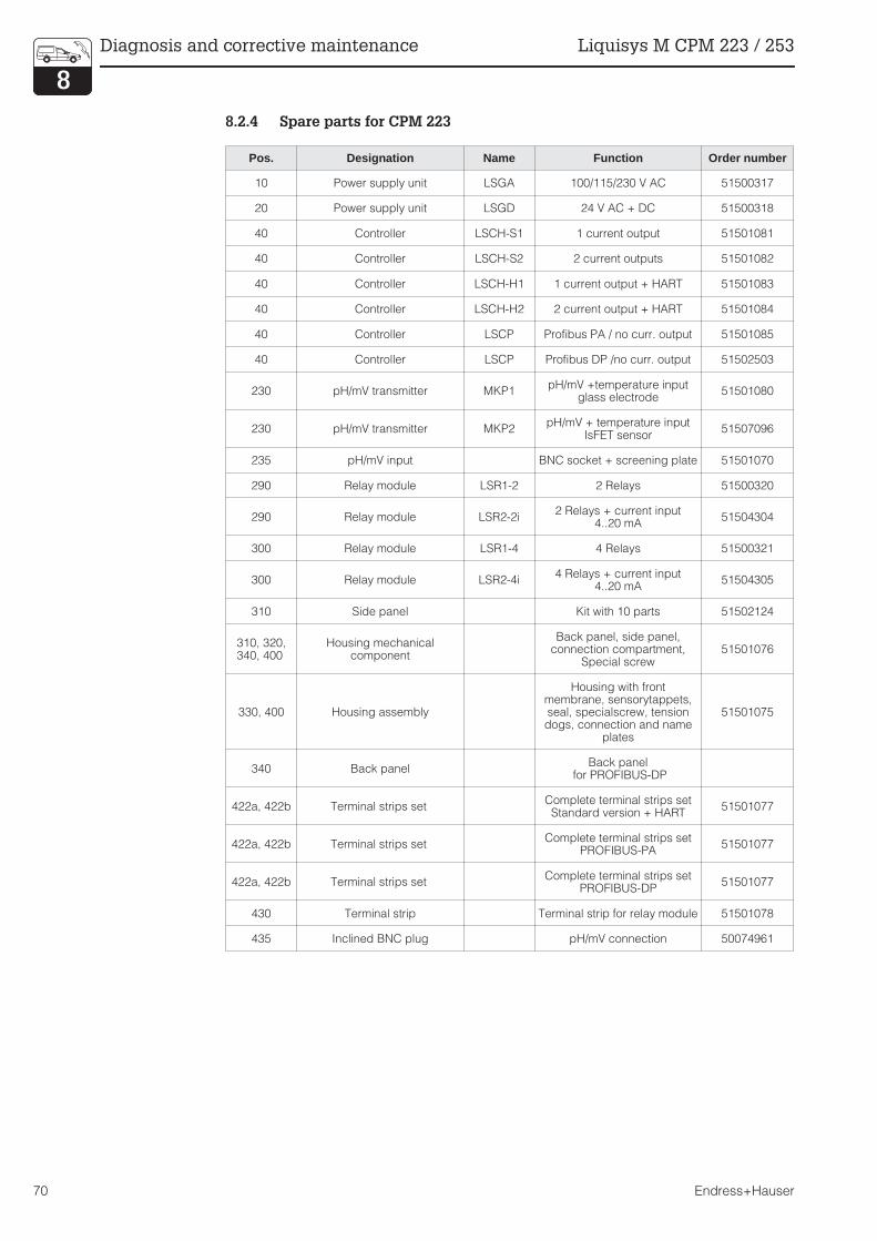
8.2.4 Spare parts for CPM 223
Pos. Designation Name Function Order number
10 Power supply unit LSGA 100/115/230 V AC 51500317
20 Power supply unit LSGD 24 V AC + DC 51500318
40 Controller LSCH-S1 1 current output 51501081
40 Controller LSCH-S2 2 current outputs 51501082
40 Controller LSCH-H1 1 current output + HART 51501083
40 Controller LSCH-H2 2 current output + HART 51501084
40 Controller LSCP Profibus PA / no curr. output 51501085
40 Controller LSCP Profibus DP /no curr. output 51502503
230 pH/mV transmitter MKP1pH/mV +temperature input
glass electrode51501080
230 pH/mV transmitter MKP2pH/mV + temperature input
IsFET sensor51507096
235 pH/mV input BNC socket + screening plate 51501070
290 Relay module LSR1-2 2 Relays 51500320
290 Relay module LSR2-2i2 Relays + current input
4..20 mA51504304
300 Relay module LSR1-4 4 Relays 51500321
300 Relay module LSR2-4i4 Relays + current input
4..20 mA51504305
310 Side panel Kit with 10 parts 51502124
310, 320,340, 400
Housing mechanicalcomponent
Back panel, side panel,connection compartment,
Special screw51501076
330, 400 Housing assembly
Housing with frontmembrane, sensorytappets,seal, specialscrew, tensiondogs, connection and name
plates
51501075
340 Back panelBack panel
for PROFIBUS-DP
422a, 422b Terminal strips setComplete terminal strips setStandard version + HART
51501077
422a, 422b Terminal strips setComplete terminal strips set
PROFIBUS-PA51501077
422a, 422b Terminal strips setComplete terminal strips set
PROFIBUS-DP51501077
430 Terminal strip Terminal strip for relay module 51501078
435 Inclined BNC plug pH/mV connection 50074961
Diagnosis and corrective maintenance Liquisys M CPM 223 / 253
70 Endress+Hauser
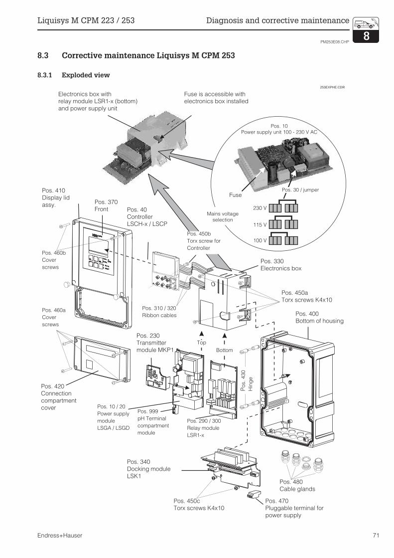
8.3 Corrective maintenance Liquisys M CPM 253
8.3.1 Exploded view
100 V
Pos. 10
Netzteil 100 – 230 V AC
230 V
115 V
SicherungPos. 30 / Steckbrücke
Netzspannungs-
wahl
Pos. 30 / jumper
Pos. 10
Power supply unit 100 - 230 V AC
Fuse
Mains voltage
selection
253EXPHE.CDR
Electronics box with
relay module LSR1-x (bottom)
and power supply unit
Fuse is accessible with
electronics box installed
Pos. 410
Display lid
assy.
Pos. 460b
Cover
screws
Pos. 460a
Cover
screws
Pos. 420
Connection
compartment
cover
Pos. 40
Controller
LSCH-x / LSCP
Pos. 370
Front
Pos. 310 / 320
Ribbon cables
Pos. 230
Transmitter
module MKP1
Pos. 10 / 20
Power supply
module
LSGA / LSGD
Pos. 999
pH Terminal
compartment
module
Pos. 340
Docking module
LSK1
Pos. 290 / 300
Relay module
LSR1-x
Pos. 450c
Torx screws K4x10
Pos. 480
Cable glands
Pos. 470
Pluggable terminal for
power supply
Pos. 330
Electronics box
Pos. 450b
Torx screw for
Controller
Top
Bottom
Pos.
430
Hin
ge
Pos. 450a
Torx screws K4x10
Pos. 400
Bottom of housing
PM253E08.CHP
Liquisys M CPM 223 / 253 Diagnosis and corrective maintenance
Endress+Hauser 71

8.3.2 Disassembly of CPM 253
• Open and remove the connectioncompartment cover (Pos. 420).
• Pull out the mains terminal (Pos. 470) tomake the device voltage-free.
• Open the display cover (Pos. 410) andloosen the ribbon cable (Pos. 310 / 320) onthe side of the electronics box (Pos. 330).
• Dismantling the controller (Pos. 40):Loosen screw (Pos. 450b) in the display lid.
• Removal of electronics box (Pos. 330):Loosen screws (Pos. 450a) in the bottom ofthe housing 2 revolutions, then slide entirebox backward and remove towards the top.
Make absolutely sure that the module locks
do not open!
Bend the module latches outward and
remove the module(s).
• Dismantling the docking module (Pos. 340):Loosen screws (Pos. 450c) in the bottom ofthe housing and remove entire moduletowards the top.
• Dismantling the pH/mV Transmitter(Pos. 230):– Bend the screen plate upward
– Pull off the stranded wire (plug-in
connection; pH input from BNC socket),
then pull off the module towards the top.
8.3.3 Assembly of CPM 253
• Insert the module(s) in the electronics boxguide rails carefully and latch into thelateral lugs in the box.
• Incorrect assembly is not possible!Modules incorrectly inserted into theelectronics box can not be put into
operation because the ribbon cables can
not be plugged in if this is the case.
• Make sure that the cover gaskets are intactsince they are required to guaranteeprotection class IP 65.
Diagnosis and corrective maintenance Liquisys M CPM 223 / 253
72 Endress+Hauser

8.3.4 Spare parts for CPM 253
Pos. Designation Name Function Order number
10 Power supply unit LSGA 100/115/230 V AC 51500317
20 Power supply unit LSGD 24 V AC + DC 51500318
40 Controller LSCH-S1 1 current output 51501081
40 Controller LSCH-S2 2 current outputs 51501082
40 Controller LSCH-H1 1 current output + HART 51501083
40 Controller LSCH-H2 2 current output + HART 51501084
40 Controller LSCP Profibus PA/no current output 51501085
40 Controller LSCP Profibus DP /no current output 51502503
230 pH/mV transmitter MKP1pH/mV +temperature input
glass electrode51501080
230 pH/mV transmitter MKP2pH/mV + temperature input
IsFET sensor51507096
230 pH/mV transmitter MKP1 pH/mV + temperature input 51501080
290 Relay module LSR2-2 2 Relays 51500320
290 Relay module LSR2-2i2 Relays + current input
4..20 mA51504304
300 Relay module LSR2-4 4 Relays 51500321
300 Relay module LSR2-4i4 Relays + current input
4..20 mA51504305
310, 320 Ribbon cables 2 ribbon cables 51501074
330, 340,450
Internal housing partsDocking assembly, empty
electronics box, small parts51501073
370, 410,420, 430,
460Housing cover
Display cover, connectioncompartment cover, Frontmembrane, hinges, cover
screws, small parts
51501068
400, 480 Lower housing section Lower section screw union
430 Hinges 2 pairs of hinges 51501069
470 Terminal strip Terminal strip for power supply 51501079
999 pH/mV terminal asembly 1 pH/mV terminal+screen plate 51501071
PM253E08.CHP
Liquisys M CPM 223 / 253 Diagnosis and corrective maintenance
Endress+Hauser 73

8.3.5 Special case: replacement of central module
Note:
• After controller replacement all theeditable data are reset to thefactory settings.
• The serial number can only be
entered – and only once – in thecase of a new module from thefactory with serial number 0000!Make sure that your entry iscorrect before confirming withENTER!Entry of an incorrect code willprevent the enhanced functionsfrom being enabled. An incorrectserial number can only becorrected at the factory.
Proceed as described below after central
module replacement:
• If possible, record the user settings of theinstrument, e.g.:– Calibration data
– pH / mV and temperature current
assignments
– Relay function selections
– Limit / controller settings
– Cleaning settings
– Monitoring functions
– Interface parameters
• Dismantle the device as described inChap. 8.2.2 or 8.3.2 .
• Refer to the part no. of the central moduleto determine whether the new module hasthe same part no. as the old one.
• Reassemble the device with the newmodule, as described in chap. 8.2.3 or8.3.3.
• Put the device into operation again andcheck the fundamental function (e.g.measured value and temperature display,operability via keyboard).
• Enter the instrument serial number:– Read the serial number (“user-no.”) of the
device from the nameplate.
– Enter this number in the fields E115 (year,
one-digit), E116 (month, one-digit),
E117 (sequence number, four-digit).
– Field E118 displays the complete number
for verification; acknowledge with ENTER
or abort and re-enter.
• Check if the S packet has been activated(e. g. by calling up the function groupCHECK / P code) or the Chemocleanfunction.
• Restore the user settings of the instrument.
8.4 Spare parts orders
Spare parts are to be ordered from your local
E+H Sales Agency. The address is on the
back cover of these operating instructions.
Use the order numbers listed in Chapters
8.2.4 and 8.3.4
To be on the safe side, you should alwaysspecify the following data with spare parts
orders:
– Instrument order code (order code)
– Serial number (user-no.)
– Software version where available
Refer to the nameplate for the order code and
serial number.
The software version is displayed in field
E111 when the instrument processor system
is functional.
8.5 Service equipment “Optoscope” with “Scopeware”
The Optoscope together with the
“Scopeware” software offers the following
possibilities, without having to remove or
open the Liquisys M and without galvanic
connection to the device:
• Documentation of the instrument settings inconjunction with Commuwin II
• Software update by the service technician• Upload/download a hex dump to duplicate
configurations.
The optoscope serves as an interface
between the Liquisys M and PC / laptop. The
information exchange takes place via the
optical interface on the Liquisys M and via an
RS 232 interface on the PC / laptop.
Handling and operation are described in the
optoscope operating instructions. The
user-friendly Windows software required for
the PC or laptop is supplied with the
optoscope.
The optoscope is supplied in a sturdy case
with all the accessories required.
Order number of optoscope: 51500650
Diagnosis and corrective maintenance Liquisys M CPM 223 / 253
74 Endress+Hauser

8.6 Corrective maintenance of measuring system
8.6.1 pH/redox transmitter
Cleaning the front panel
To clean the front panel, only use standard
cleaning agents.
The front panel is resistant to the following
cleaning agents (acc. to test methode
DIN 42 115):
• Isopropanol• Thinned acids (3 %)• Thinned alkalis (5 %)• Ester• Hydrocarbons• Ketone• Household cleaners
Caution!
Do not use any concentrated mineralacids or alkalis, benzyl-alcohol,methylene chloride or high-pressurewater vapour at over 100 °C.
8.6.2 pH/mV electrodes
Clean soilings on the glass electrodes as
follows:
• Clean oily and greasy coatingsClean with detergent (fat solvent,e.g. alcohol, acetone, poss. detergent).
Warning:
Hands, eyes and clothes are to beprotected when using the cleaningagents described below.
• Limestone deposits or metal hydroxidecoatingsLoosen coatings with diluted hydrochloridacid (3 %), then rinse thoroughly.
• Coatings containing sulphide (from fluegas desulphurising plants or sewagetreatment plants)Use mixture of hydrochlorid acid (0.5 %)and thiourea (8 %), then rinse thoroughly.
• Coatings containing protein (food industry)Use mixture of hydrochlorid acid (0.5 %)and pepsin (1 %), then rinse thoroughly.
Blocked diaphragms can under certain
circumstances be mechanically cleaned
(does not apply for teflon diaphragms and
open ring junction electrodes):
• Use a small key file• File in one direction only
Air bubbles in the electrode• Air bubbles may indicate an assembly
problem; check installation position• The range from 15° to 165° from the
horizontal is permissible• Horizontal installation or installation with the
plug-in head pointing down is not allowed
Redox electrodesCareful mechanical cleaning of coated metal
pins or surfaces is possible.
8.6.3 Assembly
Please refer to the operating instructions for
the assembly in question for maintenance and
troubleshooting instructions. The operating
instructions also include instructions for
assembly and dismantling, sensor and gasket
replacement as well as information on
resistance, spare parts and accessories.
8.6.4 Liquid KCl supply
• KCI must flow without bubbles.Unpressurised version: cotton threadpresent?
• For counterpressure: pressure in KClreservoir must exceed medium pressureby at least 0.8 bar.
• KCl consumption should be low butnoticeable. Approx. 1 ... 10 ml per day istypical.
• Refill opening of sensors with KCI refillopening on glass shaft must be open.
> 15° > 15°
PM253E08.CHP
Liquisys M CPM 223 / 253 Diagnosis and corrective maintenance
Endress+Hauser 75
8.6.5 Connecting lines and junction boxes
Check cables and connections for moisture.
Moisture reduces the sensor slope. If the
display can not be called up or is fixed on
pH 7, please check the following components:
• Sensor head• Sensor plug• pH measuring cable• Junction box if present• Extension cable
Note:
The sensor head and junction boxcan be cleaned and dried with ahair-drier.
Caution:
If moisture is found on themeasuring cable, the cableabsolutely must be replaced.
A shunt in the cable of > 20 MΩ cannot be
measured with normal multimeters, but is very
detrimental to pH measurement. Reliable
testing is possible with a commercially
available insulation resistance meter:
• Disconnect the pH measuring cable fromthe sensor and instrument.
• If a junction box is used, the incoming andoutgoing pH cables should be checkedseparately.
• Preferably test the cable with a test voltageof 1000 V DC (but least with 500 V DC) test.
• Insulation resistance of an intact cable is> 100 GΩ.
• Defective (moist) cables will causeflashover.Cable replacement is mandatory!
Diagnosis and corrective maintenance Liquisys M CPM 223 / 253
76 Endress+Hauser
9 Accessories
Mounting accessories
• Weather protection cover CYY 101For mounting on field housing,for outdoor installation.Dimensions (H × W × D):320 × 300 × 270 mmMaterial: Stainless steel SS 304Order no.: CYY 101-A
• Universal upright post CYY 102Square tube for mounting offield housing.Dimensions (H × W × D):1495 × 60 × 60 mmMaterial: Stainless steel SS 304Order no.: CYY 102-A
Electrodes
• OrbiSint W CPS 11/12/13pH / redox combination electrodewith PTFE diaphragms, with gel filling,applicable for up to 6 bar.Technical Information TI 028C/07/enOrder no.: 50054649
• OrbiTex W CPS 21pH combination electrodewith open ring junction, with gel filling,applicable for up to 6 bar.Technical Information TI 029C/07/deOrder no.: 50054650
• CeraTex W CPS 31pH combination electrodewith ceramic diaphragms, with electrolytefilling, applicable for up to 0.6 bar.Technical Information TI 030C/07/deOrder no.: 50054651
• CeraLiquid P CPS 41/42/43pH combination electrodewith ceramic diaphragms, electrolyteconnection via threaded hose coupling,applicable for up to 8 bar.Technical Information TI 049C/07/deOrder no.: 50059346
• CeraGel P CPS 71/72Sterilisable pH/redox electrode with doublechamber reference and integrated bridgeelectrolyte.Technical Information TI 245C/07/deOrder no.: 51505837
• TopHit H CPS 401IsFET sensor for glass-free pHmeasurement from PEEK. With long-termstable contamination-resistant referencesystem.Technical Information TI 283C/07/deOrder no.: 51506685
Connection accessories
Technical information about all cable types:TI 118C/07/enOrder no.: 50068526
• CPK1Measuring cable with auxiliary core and
additional outer screen, in PVC sheath,
∅ 7.2 mm; extension with cable CYK 71
• CPK 2Coaxial measuring cable with six auxiliarycores and additional outer screen, in PVC
sheath, ∅ 12 mm; extension with cablePMK
• CPK 9Coaxial measuring cable with four auxiliarycores and additional outer screen, in PVC
sheath, ∅ 7.2 mm; with waterproof TOP 68plug-in head, IP68 ingress protection,extension with cable CYK 71
• CPK 12Coaxial measuring cable with four auxiliarycores and additional outer screen, in PVC
sheath, ∅ 7.2 mm; for IsFET sensors, withwaterproof TOP68 plug-in head, IP 68ingress protection, extension with cableCYK 71
• Junction box VBMJunction box for extension of cableconnection between electrode andinstrument. Pg 13.5 cable entries.Material: cast aluminium;Ingress protection: IP 65.Order no.: 50003987
• Junction box VBAJunction box for extension of cableconnection between electrode andinstrument. Pg 13.5 cable entries.Material: cast aluminium;Ingress protection: IP 65Order no.: 50005276
PM253E09.CHP
Liquisys M CPM 223 / 253 Accessories
Endress+Hauser 77

Assemblies
• DipFit W CPA 111Immersion assembly for pH andredox electrodes with bayonet system,applicable for up to 4 bar.Technical Information TI 112C/07/deOrder no.: 50066450
• CleanFit W CPA 450Manual change assembly for pH andredox electrodes, applicable for up to4 bar.Technical information TI 183C/07/enOrder no.: 50090677
• CleanFit P CPA 471Process retractable assembly for pH andredox electrodes, for manual or pneumaticoperation, applicable for up to 6 bar.Stainless steel material.Technical information TI 217C/07/enOrder no.: 51502596
• CleanFit P CPA 472Process retractable assembly for pH andredox electrodes, for manual or pneumaticoperation, applicable for up to 6 bar.Plastic material.Technical information TI 223C/07/enOrder no.: 51502645
• FlowFit CPA 250Flow assembly for pH andredox electrodes, applicable for up to 6 barTechnical information TI 041C/07/enOrder no.: 50036058
Buffer solutions
• CPY 1 High precision buffer solutionfor pH calibrationpH 2.0 / 11.0Content: 100 ml
• CPY 2 Technical buffer solutionfor pH calibrationpH 4.0 / 7.0 / 9.2 / 10.00Content: 100 / 1000 / 5000 ml
• CPY 3for redox calibration+220 mV (pH 7,0)+ 468 mV (pH 0,0)Content: 100 / 5000 ml
• CPY 4KCl electrolyte solutionfor liquid filled electrodes3 mol (-10 °C ... 100 °C)1.5 mol (-30 °C ... 100 °C)Content: 100 / 1000 ml
Instrument upgrade
(Order only possible with serial number ofrelevant device)
• Plus packageOrder no.: 51500385
• ChemoCleanOrder no.: 51500963
• Two-relay card (standard version)Order no.: 51500320
• Two-relay card (CSA version)Order no.: 51511446
• Four-relay card (standard version)Order no.: 51500321
• Four-relay card (CSA version)Order no.: 51511447
• Two-relay card with current input(standard version / CSA version)Order no.: 51504304
• Four-relay card with current input(standard version / CSA version)Order no.: 51504305
Accessories Liquisys M CPM 223 / 253
78 Endress+Hauser

10 Technical data
General specifications Manufacturer Endress+Hauser
Product designation Liquisys M CPM 223
Liquisys M CPM 253
Input Measured variables pH, redox, temperature
pH measurement
Measuring range pH –2 ... 16
Display range pH –2 ... 16
with indication of measuring range violation
pH offset range ±pH 2
Slope Glass: 38.00 ... 65.00 mV/pH (nominal 59.16 mV/pH)
Antimon: 25.00 ... 65.00 mV/pH (nominal 59.16 mV/pH)
IsFET: 38.00 ... 65.00 mV/pH (nominal 59.16 mV/pH)
Zero point Glass: pH 5.00 ... 9.00 (nominal pH 7.00)
Antimon: pH –1.00 ... 3.00 (nominal pH 1.00)
IsFET: –500 ... +500 mV
Terminal cross-section 2.5 mm2
Required conductor cross-section CPM 223
CPM 253
0.75 mm2 / AWG 18
1.50 mm2 / AWG 14
Maximum cable length to pH electrode 50 m
pH signal input
Input resistance for nominal operating conditions > 1 × 10¹² Ω
Redox measurement
Display and measuring range –1500 ... +1500 mV / 0 ... 100 %
Redox offset range ±120 mV / ±50 %
Terminal cross-section 2.5 mm2
Required conductor cross-section CPM 223
CPM 253
0.75 mm2 / AWG 18
1.50 mm2 / AWG 14
Maximum cable length to pH electrode 50 m
Redox signal input
Input resistance for nominal operating conditions > 1 × 10¹² Ω
Temperature measurement
Temperature sensor Pt 100, Pt 1000, NTC 30K
Measuring range Pt 100, Pt 1000
NTC 30K
–50 ... +150 °C
–20 ... +100 °C
Temperature offset range ±5 °C
Digital inputs 1 and 2
Voltage 10 ... 50 V
Current consumption max. 10 mA
Current input
Current range 4 ... 20 mA, galvanically separated
Load 260 Ω at 20 mA (voltage drop 5.2 V)
%Ω°C
PM253E10.CHP
Liquisys M CPM 223 / 253 Technical data
Endress+Hauser 79
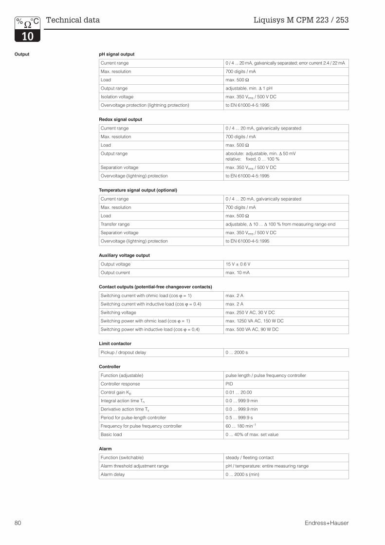
Output pH signal output
Current range 0 / 4 ... 20 mA, galvanically separated; error current 2.4 / 22 mA
Max. resolution 700 digits / mA
Load max. 500 Ω
Output range adjustable, min. ∆ 1 pH
Isolation voltage max. 350 Vrms / 500 V DC
Overvoltage protection (lightning protection) to EN 61000-4-5:1995
Redox signal output
Current range 0 / 4 ... 20 mA, galvanically separated
Max. resolution 700 digits / mA
Load max. 500 Ω
Output range absolute: adjustable, min. ∆ 50 mV
relative: fixed, 0 ... 100 %
Separation voltage max. 350 Vrms / 500 V DC
Overvoltage (lightning) protection to EN 61000-4-5:1995
Temperature signal output (optional)
Current range 0 / 4 ... 20 mA, galvanically separated
Max. resolution 700 digits / mA
Load max. 500 Ω
Transfer range adjustable, ∆ 10 ... ∆ 100 % from measuring range end
Separation voltage max. 350 Vrms / 500 V DC
Overvoltage (lightning) protection to EN 61000-4-5:1995
Auxiliary voltage output
Output voltage 15 V ± 0.6 V
Output current max. 10 mA
Contact outputs (potential-free changeover contacts)
Switching current with ohmic load (cos ϕ = 1) max. 2 A
Switching current with inductive load (cos ϕ = 0.4) max. 2 A
Switching voltage max. 250 V AC, 30 V DC
Switching power with ohmic load (cos ϕ = 1) max. 1250 VA AC, 150 W DC
Switching power with inductive load (cos ϕ = 0,4) max. 500 VA AC, 90 W DC
Limit contactor
Pickup / dropout delay 0 ... 2000 s
Controller
Function (adjustable) pulse length / pulse frequency controller
Controller response PID
Control gain Kp 0.01 ... 20.00
Integral action time Tn 0.0 ... 999.9 min
Derivative action time Tv 0.0 ... 999.9 min
Period for pulse-length controller 0.5 ... 999.9 s
Frequency for pulse frequency controller 60 ... 180 min–1
Basic load 0 ... 40% of max. set value
Alarm
Function (switchable) steady / fleeting contact
Alarm threshold adjustment range pH / temperature: entire measuring range
Alarm delay 0 ... 2000 s (min)
%Ω°C Technical data Liquisys M CPM 223 / 253
80 Endress+Hauser
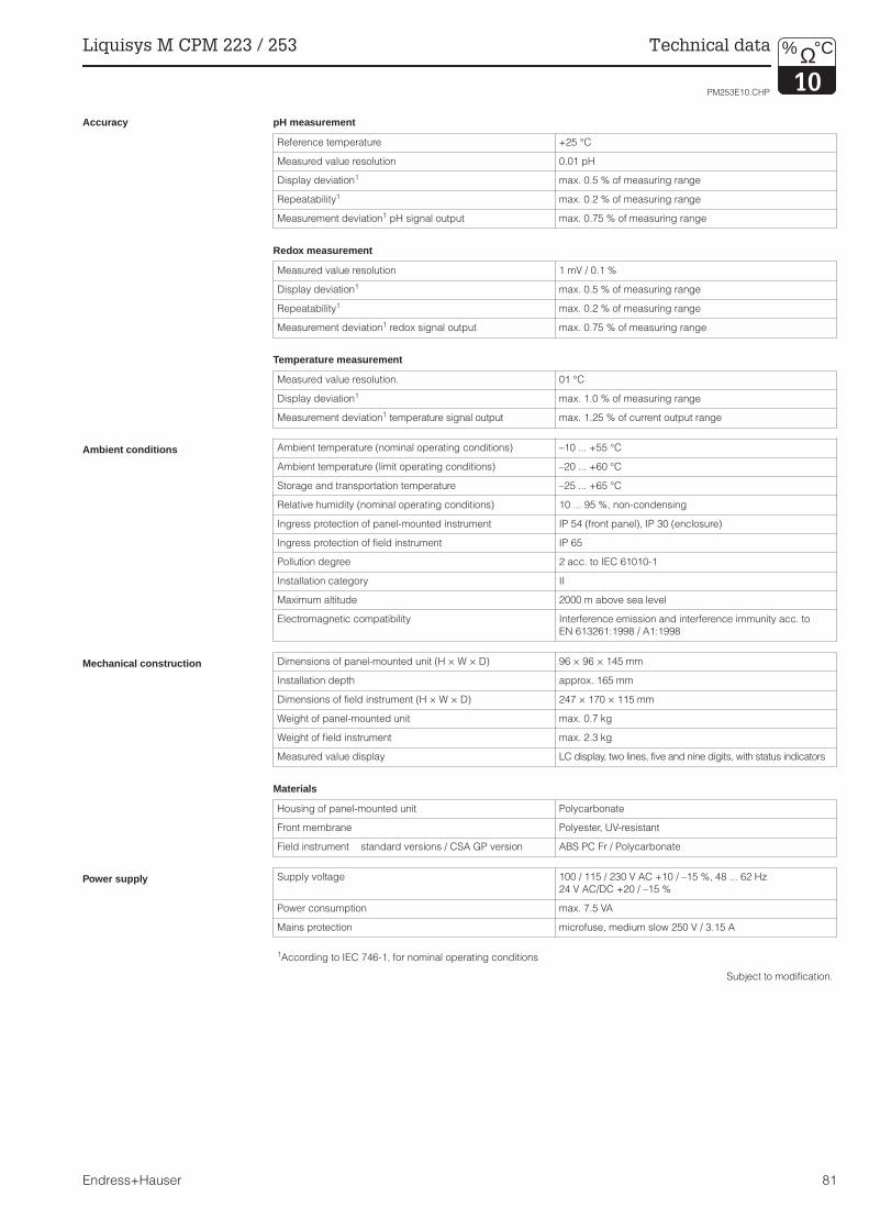
Accuracy pH measurement
Reference temperature +25 °C
Measured value resolution 0.01 pH
Display deviation1 max. 0.5 % of measuring range
Repeatability1 max. 0.2 % of measuring range
Measurement deviation1 pH signal output max. 0.75 % of measuring range
Redox measurement
Measured value resolution 1 mV / 0.1 %
Display deviation1 max. 0.5 % of measuring range
Repeatability1 max. 0.2 % of measuring range
Measurement deviation1 redox signal output max. 0.75 % of measuring range
Temperature measurement
Measured value resolution. 01 °C
Display deviation1 max. 1.0 % of measuring range
Measurement deviation1 temperature signal output max. 1.25 % of current output range
Ambient conditions Ambient temperature (nominal operating conditions) –10 ... +55 °C
Ambient temperature (limit operating conditions) –20 ... +60 °C
Storage and transportation temperature –25 ... +65 °C
Relative humidity (nominal operating conditions) 10 ... 95 %, non-condensing
Ingress protection of panel-mounted instrument IP 54 (front panel), IP 30 (enclosure)
Ingress protection of field instrument IP 65
Pollution degree 2 acc. to IEC 61010-1
Installation category II
Maximum altitude 2000 m above sea level
Electromagnetic compatibility Interference emission and interference immunity acc. to
EN 613261:1998 / A1:1998
Mechanical construction Dimensions of panel-mounted unit (H × W × D) 96 × 96 × 145 mm
Installation depth approx. 165 mm
Dimensions of field instrument (H × W × D) 247 × 170 × 115 mm
Weight of panel-mounted unit max. 0.7 kg
Weight of field instrument max. 2.3 kg
Measured value display LC display, two lines, five and nine digits, with status indicators
Materials
Housing of panel-mounted unit Polycarbonate
Front membrane Polyester, UV-resistant
Field instrument standard versions / CSA GP version ABS PC Fr / Polycarbonate
Power supply Supply voltage 100 / 115 / 230 V AC +10 / –15 %, 48 ... 62 Hz
24 V AC/DC +20 / –15 %
Power consumption max. 7.5 VA
Mains protection microfuse, medium slow 250 V / 3.15 A
1According to IEC 746-1, for nominal operating conditions
Subject to modification.
%Ω°C
PM253E10.CHP
Liquisys M CPM 223 / 253 Technical data
Endress+Hauser 81
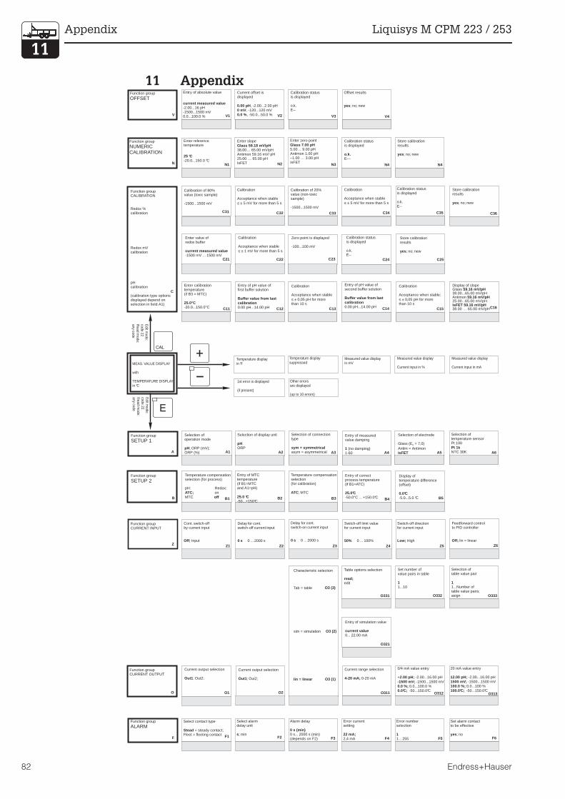
11 Appendix
V
Z
N
V2
N2
V3
N3
V4
N4 N4
V1
N1
C
C13 C15C11 C12 C14 C16
C25C23 C24C22
C32 C34 C36C35C31 C33
C21
A A1 A2 A3 A4 A5 A6
B B1 B2 B3 B4 B5
F F1 F2 F3 F4 F5 F6
O O1 O2
O3 (3)
O3 (2)
O3 (1)
O311 O312 O313
O321
O331 O332 O333
Z1 Z2 Z3 Z4 Z5 Z6Z
Current offset isdisplayed
, -2.00...2.00 pH, -120...120 mV, -50.0...50.0 %
0.00 pH0 mV0.0 %
Function group
OFFSET
Function group
NUMERICCALIBRATION
Calibration statusis displayed
o.k.E--
Offset results
; no; newyes
Entry of absolute value
-2.00...16 pH-1500...1500 mV0.0...100.0 %
current measured value
Enter slope
38.00… 65.00 mV/pHAntimon 59.16 mV/ pH25.00 … 65.00 pHIsFET
Glass 59.18 mV/pHEnter zero point
5.00… 9.00 pHAntimon 1.00 pH–1.00 … 3.00 pHIsFET
Glass 7.00 pHCalibration statusis displayed
E---o.k.
Store calibrationresults
; no; newyes
Enter referencetemperature
25 °C-20.0...150.0 °C
Function groupCALIBRATION
Redox %calibration
Redox mVcalibration
pHcalibration
(calibration type optionsdisplayed depend onselection in field A1)
Calibration
Acceptance when stable0,05 pH for more
than 10 s≤ ±
Calibration
Acceptance when stable:0,05 pH for more
than 10 s≤ ±
Enter calibrationtemperature(if B3 = MTC)
-20.0...150.0 C25.0 C°
°
Entry of pH value offirst buffer solution
0.00 pH...14.00 pH
Buffer value from lastcalibration
Entry of pH value ofsecond buffer solution
0.00 pH...14.00 pH
Buffer value from lastcalibration
Store calibrationresults
; no; newyes
Zero point is displayed
-100...100 mV
Calibration statusis displayed
o.k.E--
Calibration
Acceptance when stable1 mV for more than 5 s≤ ±
Calibration
Acceptance when stable5 mV for more than 5 s≤ ±
Calibration
Acceptance when stable5 mV for more than 5 s≤ ±
Calibration statusis displayed
o.k.E--
Calibration of 80%value (toxic sample)
-1500...1500 mV
Calibration of 20%value (non-toxicsample)
-1500...1500 mV
Enter value ofredox buffer
-1500 mV ... 1500 mVcurrent measured value
Display of slopeGlass38.00...65.00 mV/pHAntimon25.00...65.00 mV/pH
38.00 … 65.00 mV/pH
59.16 mV/pH
59.16 mV/pH
IsFET 59.16 mV/pH
Store calibrationresults
; no; newyes
MEAS. VALUE DISPLAY
with
TEMPERATURE DISPLAYin °C
Measured value displayin mV
Temperature displaysuppressed
Temperature displayin °F
Other errorsare displayed
(up to 10 errors)
1st error is displayed
(if present)
Editm
ode:code 22R
eadm
ode:any
code
Editm
ode:code 22R
eadm
ode:any
code
Measured value display
Current input in %
Measured value display
Current input in mA
Function group
SETUP 1Selection ofoperation mode
; ORP (mV);ORP (%)pH
Selection of connectiontype
asym = asymmetricalsym = symmetrical
Selection of display unit
ORPpH
Entry of measuredvalue damping
(no damping)1-601
Selection of electrode
Glass (E = 7,0)Antim = Antimon
0
IsFET
Selection oftemperature sensorPt 100
NTC 30KPt 1k
Function group
SETUP 2Temperature compensationselection (for process)
pH: Redox:on
MTCATC;
off
Entry of MTCtemperature(if B1=MTCand A1=pH)
-50...+15025.0 °C
°C
Temperature compensationselection(for calibration)
; MTCATC
Entry of correctprocess temperature(if B1=ATC)
25.0°C-50.0°C ... +150.0°C
Display oftemperature difference(offset)
0.0°C-5.0...5.0 °C
Cont. switch-offby current input
InputOff;
Switch-off directionfor current input
HighLow;
Feedforward controlto PID controller
lin = linearOff;
Delay for cont.switch-off current input
0 ... 2000 s0 s
Delay for cont.switch-on current input
0 ... 2000 s0 s
Switch-off limit valuefor current input
0 ... 100%50%
Function groupCURRENT INPUT
Function groupCURRENT OUTPUT
Current output selection
; Out2;Out1
Current output selection
; Out2;Out1
Characteristic selection
Tab = table
sim = simulation
lin = linear
Current range selection
0-20 mA4-20 mA;
0/4 mA value entry
+ -2.00...16.00 pH-1500...1500 mV
0.0...100.0 %
2.00 pH;-1500 mV;0.0 %;0.0°C; -50...150.0°C
20 mA value entry
-2.00...16.00 pH-1500...1500 mV
0.0...100 %
12.00 pH;1500 mV;100.0 %;100.0°C; -50...150.0°C
Entry of simulation value
0... 22.00 mAcurrent value
Table options selection
editread;
Set number ofvalue pairs in table
1...101
Seleciton oftable value pair
1...Number oftable value pairs;asign
1
Function groupALARM
Select contact type
= steady contact;Fleet = fleeting contactStead
Select alarmdelay unit
; mins
Alarm delay
0 s... 2000 s (min)(depends on F2)
0 s (min)
Error currentsetting
2,4 mA22 mA;
Error numberselection
1... 2551
Set alarm contactto be effective
; noyes
Appendix Liquisys M CPM 223 / 253
82 Endress+Hauser

C19C17 C18
F8F7 F9
O335 O336O334
Z7
Feedforward control =1at
0 … 100%50%
Store calibrationresults
; no; newyes
Zero point is displayedGlass5.00...9.00 pHAntimon-1.00...3.00 pHIsFET–500...+500 mV
7.00 pH
1.00 pH
current value
Calibration statusis displayed
o.k.E--
Field for customer settings
Automatic start ofcleaning function
; yes(not always displayed,see error messages)
no
Activate error currentfor previously seterror
yesno;
Select “next error”or return to menu
;R
next = next error←
Entry of y value(current value)
0.00...20.00 mA0.00 mA
Table status ok
; noyes
Entry of x value(measured value)
-2.00...16.00 pH-1500...1500 mV0.0...100.0 %
0.00 pH;0 mV;0.0 %;
PM253E11.CHP
Liquisys M CPM 223 / 253 Appendix
Endress+Hauser 83
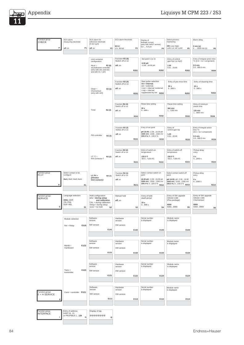
R
Function groupRELAY
Select contact to beconfigurd
Rel2; Rel3; Rel4;Rel1;
R1
R2 (6)
R2 (5)
R2 (4)
R2 (3)
R2 (2)
R2 (1)
FunctionSwitch off or on
; on
R2 (2)
off
R221
Entry of switch-ontemperature
150.0 °C-50.0...+150.0°C
R222
Entry of switch-offtemperature
150.0 °C-50.0...+150.0°C
Pickup delayentry
0...2000 s0 s
R224R223
FunctionSwitch off or on
; on
R2 (3)
off
R231
Entry of set point
-2.00...16.00 pH-1500...1500 mV
0...100.0 %
pH 16.00;1500 mV;100.0 %;
R232
Entry ofcontrol gain Kp
0.01...20.001.00
R233
Entry of integral actiontime Tn(0.0 = no I component)
0.0...999.9 min0.0 min
R234
FunctionSwitch off or on
; on
R2 (4)
off
R241
Rinse time setting
0...999 s30 s
R242
Pause time setting
1...7200 min360 min
Entry of minimumpause time
1...3600 min120 min
R243 R244
FunctionSwitch off or on
; on
R2 (1)
off
R211
Select contact switch-onpoint
; -2.00...16.00 pH; -1500...1500 mV
; 0...100.0 %
16.00 pH1500 mV100.0 %
R212
Select contact switch-offpoint
pH -2.00...16.00-1500...1500 mV
0...100.0 %
pH 16.00;1500 mV;100.0 %; R213
Pickup delayentry
0...2000 s0 s
R214
Entry of integral action timeTn (0.0 = no I component)
0.0...999.9 min0.0 min
R264
FunctionSwitch off or on
on
R2 (6)
off;
R261 R262 R263
Set point 1 (or 2)
-2.00...16.00 pH6.00 pH
Entry of controlgain Kp1 (or Kp2)
0.01...20.001.00
FunctionSwitch off or on
; on
R2 (5)
off
R251
Entry of pre-rinse time
0...999 s30 s
R253
Entry of cleaning time
0...999 s10 s
R254
Start pulse selection;
ext = external;i+ext = internal +external;i+stp = internal,suppressed by ext
int = internal
R252
Limit contactorconfiguration
Neutr =neutralisation controller(only with rel1 and rel2and with A1 = pH)
Clean =Chemoclean(only with rel3)
Timer
PID controller
LC °C =limit contactor T
LC PV =pH/redoxlimit contactor
Function groupSERVICE
S
Language selection
GERITA; FRAESP; NEL
ENG;
S1
Hold configuration=
CAL = during calibrationSetup = during setupnone = no hold
s+c during setupand calibration
S2
Softwareversion
SW version
E111
Hardwareversion
HW version
E112
Serial numberis displayed
E113 E114
Softwareversion
SW version
E121
Hardwareversion
HW version
E122
Serial numberis displayed
E123 E124
Softwareversion
SW version
E131
Hardwareversion
HW version
E132
Serial numberis displayed
E133 E134
Softwareversion
SW version
E141
Hardwareversion
HW version
E142
Serial numberis displayed
Module nameis displayed
Module nameis displayed
Module nameis displayed
Module nameis displayed
E143 E144
Entry of holddwell period
0...999 s10 s
S4
Manual hold
onoff;
S3
Entry of SW upgraderelease code(Plus package)
0000...99990000
S5
Entry of SW upgraderelease codeChemoclean
0000...99990000
S6
Function groupINTERFACE
I
Function groupE + H SERVICE
E
Entry of addressHART: ...15or PROFIBUS 1...
0126
Module selection
Rel = Relay
MainB =mainboard
Trans =transmitter
Contr = controller
I1
E1(4)
E1(3)
E1(2)
E1(1)
Function group
CHECK
P
SCS alarmmeasuring electrode
; onoff P1
SCS alarm forreference electrode(if A2=sym)
; onoff P2
Display ofleakage current(only with IsFET sensor)0,0 … 9,9 Aµ
P4
SCS alarm threshold
1.5...50 k50 kΩ
Ω P3
Alarm delay
0 … 2000 min (s)0 min (s)
P6
Select processmonitoring
Low; High;LoHi; Lo!; Hi!; LoHi!Off;
P5
Display of tag
@@@@@@@@I2
Appendix Liquisys M CPM 223 / 253
84 Endress+Hauser

Dropout delayentry
0...2000 s0 s
R225
Entry of alarm threshold(as an absolute value)
150.0 °C-20.0...+150.0 °C
R226
Entry of derivative actiontime Tv(0.0 = no D component)
0.0...999.9 min0.0 min
R235
Selection of controlcharacteristic
inv = inverted;dir = direct;
R236
Selection
freq = pulse frequencyIen = pulse length
R237
Entry of min. ON timet
0.1...5.0 s
on
0.3 s
R2310
Entry of max.pulse frequency
60...180 1/min120 1/min
R239
Entry ofpulse interval
0.5...999.9 s10.0 s
R238
Dropout delayentry
0...2000 s0 s
R215
Entry of alarm threshold(as an absolute value)
; -2.00...16.00 pH; -1500...1500 mV
; 0...100.0 %
16.00 pH1500 mV100.0 % R216
Entry of derivative actiontime Tv(0.0 = no D component)
0.0...999.9 min0.0 min
R265
Entry of min. ON timet
0.1...5.0 s
on
0.3 s
R269
Entry of max.pulse frequency
60...180 1/min120 1/min
R268
Selection
freq = pulse frequencylen = pulse length
R266
Entry ofpulse interval
0.5...999.9 s10.0 s
R267
Entry of post-rinse time
0...999 s20 s
R255
Number of repeat cycles
0...50
R256
Set interval betweentwo cleaning cycles(pause time)
1...7200 min360 min
R257
Number of cleaningcycles withoutcleaning agent
0...90
R259
Entry of minimumpause time
1...R357 min120 min
R258
Order numberis displayed
Reference voltageis displayed
S7 S11
Serial numberis displayed
SelectAC frequency
S8 S12
Perform instrument test
; displayno
S10
Reset intrument(restore default values)
Sens = sensor data;Facty = factory settings
no;
S9
P7 P8 P10P9 P12P11
Set lower
alarm threshold
pH -2 ... 16pH -2.00
Set upperalarm threshold
pH -2 ... 16pH 16.00
Select processmonitoring
AC; CC; AC CCAC!; CC!; ACCC!Off;
Set max. perm. periodfor lower limit exceeded
0 ... 2000 min60 min
Set max. perm. periodfor upper limit exceeded
0 ... 2000 min120 min
Set monitoringvalue
pH -2 ... 16pH 1.00
Enter basic load
0 … 40%0%
Enter process type
InlneBatch
Enter process type
InlneBatch
R2311 R2312
R2610
PM253E11.CHP
Liquisys M CPM 223 / 253 Appendix
Endress+Hauser 85
12 Index
!0 . . . . . . . . . . . . . . . . . . . . . . . . . . . . . . . 18, 2122 . . . . . . . . . . . . . . . . . . . . . . . . . . . . . . . . . 219999 . . . . . . . . . . . . . . . . . . . . . . . . . . . . 18, 21
AA-Function group . . . . . . . . . . . . . . . . . . . . . 25Access codes . . . . . . . . . . . . . . . . . . . . . . . . 21Accessories . . . . . . . . . . . . . . . . . . . . . . 77, 78Actuating signal outputs . . . . . . . . . . . . . . . . 40ALARM (P) . . . . . . . . . . . . . . . . . . . . . . . . . . 33Alarm contact . . . . . . . . . . . . . . . . . . 24, 33, 34Alarm delay. . . . . . . . . . . . . . . . . . . . . . . . . . 33Alarm threshold. . . . . . . . . . . . . . . . . . . . 44, 45Assemblies . . . . . . . . . . . . . . . . . . . . . . . . . . 78Assembly of CPM 223 . . . . . . . . . . . . . . . . . 69Assembly of CPM 253 . . . . . . . . . . . . . . . . . 72Asymmetrical . . . . . . . . . . . . . . . . . . . . . . . . 15AUTO key . . . . . . . . . . . . . . . . . . . . . . . . . . . 18
BB-Function group . . . . . . . . . . . . . . . . . . . . . 26Basic load . . . . . . . . . . . . . . . . . . . . . . . . . . . 46
CC-Function group . . . . . . . . . . . . . . . 54, 55, 56Calibration. . . . . . . . . . . . . . . . . . . . . . . . 53, 54CALIBRATION (C) . . . . . . . . . . . . . . . . . . . . 23Calibration mode . . . . . . . . . . . . . . . . . . 20, 23Characteristic controller . . . . . . . . . . . . . . . . 46CHECK (P) . . . . . . . . . . . . . . . . . . . . . . . . . . 36Chemoclean function . . . . . . . . . . . . . . . 38, 42Cleaning . . . . . . . . . . . . . . . . . . . . . . . . . . . . 66Cleaning function . . . . . . . . . . . . . . . . . . . . . 47Cleaning time . . . . . . . . . . . . . . . . . . . . . 42, 48Code 0 . . . . . . . . . . . . . . . . . . . . . . . . . . . . . 18Code 22 . . . . . . . . . . . . . . . . . . . . . . . . . . . . 21Code 9999 . . . . . . . . . . . . . . . . . . . . . . . . . . 18Coding . . . . . . . . . . . . . . . . . . . . . . . . . . . . . 23Complete Installation . . . . . . . . . . . . . . . . . . . 6Complete measuring system . . . . . . . . . . . . . 6Connection diagram . . . . . . . . . . . . . . . . . . . 12Connection examples. . . . . . . . . . . . . . . . . . 15Connections of field instrument . . . . . . . . . . 13Contact selection . . . . . . . . . . . . . . . . . . . . . 33Control characteristic . . . . . . . . . . . . . . . . . . 41CPK 1, CPK 2, CPK 7 . . . . . . . . . . . . . . . . . . 14Current input . . . . . . . . . . . . . . . . . . . . . . . . . 27CURRENT INPUT (Z) . . . . . . . . . . . . . . . . . . 29CURRENT OUTPUT (O) . . . . . . . . . . . . . 23, 31Current output table . . . . . . . . . . . . . . . . . . . 32Current outputs . . . . . . . . . . . . . . . . . . . . . . . 30
DDamage. . . . . . . . . . . . . . . . . . . . . . . . . . . . . 2Declaration of conformity . . . . . . . . . . . . . . . 5Definition of terms . . . . . . . . . . . . . . . . . . . . 66Derivative action time . . . . . . . . . . . . . . . . . 45Diagnosis. . . . . . . . . . . . . . . . . . . . . . . . . 66-76Dimensions . . . . . . . . . . . . . . . . . . . . . . . . . . 7Disassembly of CPM 223 . . . . . . . . . . . . . . 69Disassembly of CPM 253 . . . . . . . . . . . . . . 72Display. . . . . . . . . . . . . . . . . . . . . . . . . . . . . 17Disposal. . . . . . . . . . . . . . . . . . . . . . . . . . . . . 2Dropout delay . . . . . . . . . . . . . . . . . . . . 43, 44
EE+H Service. . . . . . . . . . . . . . . . . . . . . . . . . 52E-Function group. . . . . . . . . . . . . . . . . . . . . 52Electrical connection . . . . . . . . . . . . . . . . . . 12Electrode installation . . . . . . . . . . . . . . . . . . 14Electrodes . . . . . . . . . . . . . . . . . . . . . . . . . . 77Electronics box . . . . . . . . . . . . . . . . . . . . . . . 7Entry of hold dwell period . . . . . . . . . . . . . . 50Error codes . . . . . . . . . . . . . . . . . . . . . . . . . 63Error current. . . . . . . . . . . . . . . . . . . . . . 33, 34
FF-Function group . . . . . . . . . . . . . . . . . . 33, 34Factory settings . . . . . . . . . . . . . . . . . . . . . . 24Freezing of outputs . . . . . . . . . . . . . . . . . . . 22Function coding. . . . . . . . . . . . . . . . . . . . . . 23Function group . . . . . . . . . . . . . . . . . . . . . . 21
GGeneral . . . . . . . . . . . . . . . . . . . . . . . . . . . 2, 3General safety notes . . . . . . . . . . . . . . . . . . . 4
HHardware version . . . . . . . . . . . . . . . . . . . . 52HART . . . . . . . . . . . . . . . . . . . . . . . . . . . . . . 52Hazards . . . . . . . . . . . . . . . . . . . . . . . . . . . . . 2Hold configuration . . . . . . . . . . . . . . . . . . . . 50Hold dwell period . . . . . . . . . . . . . . . . . . . . 42Hold function . . . . . . . . . . . . . . . . . . . . . . . . 22
II-Function group . . . . . . . . . . . . . . . . . . . . . 52Immunity to interference . . . . . . . . . . . . . . . . 5Installation . . . . . . . . . . . . . . . . . . . . . . . 4, 6-16Instrument configuration . . . . . . . . . . . . . 23-37Instrument upgrade. . . . . . . . . . . . . . . . . . . 78Integral action time . . . . . . . . . . . . . . . . . . . 45Intended application . . . . . . . . . . . . . . . . . . . 4INTERFACE (I) . . . . . . . . . . . . . . . . . . . . . . . 52Interfaces. . . . . . . . . . . . . . . . . . . . . . . . . . . 59
KKey functions. . . . . . . . . . . . . . . . . . . . . . . . 18Kp . . . . . . . . . . . . . . . . . . . . . . . . . . . . . . . . 45
Index Liquisys M CPM 223 / 253
86 Endress+Hauser

LLED indicator . . . . . . . . . . . . . . . . . . . . . . . . 17Limit contactor . . . . . . . . . . . . . . . . . . . . 38, 43Limit contactor for conductivity measuredvalue. . . . . . . . . . . . . . . . . . . . . . . . . . . . . . . 38Limit contactor for temperature . . . . . . . 38, 44Liquid crystal display . . . . . . . . . . . . . . . . . . 17Locking the keypad . . . . . . . . . . . . . . . . 18, 21
MMaintenance and troubleshooting. . . . . 60-65Maintenance of CPM 223 . . . . . . . . . . . . . . 68Maintenance of CPM 253 . . . . . . . . . . . . . . 71Maintenance of measuring system . . . . . . . 75Manual Hold. . . . . . . . . . . . . . . . . . . . . . . . . 50Measuring cable . . . . . . . . . . . . . . . . . . . . . 14Measuring cable connection . . . . . . . . . 14, 16Measuring mode . . . . . . . . . . . . . . . . . . . . . 23Measuring system . . . . . . . . . . . . . . . . . . . . . 6Menu structure . . . . . . . . . . . . . . . . . . . . . . . 21Mimimum pause time. . . . . . . . . . . . . . . . . . 48Minimum pause time . . . . . . . . . . . . . . . . . . 47MINUS key . . . . . . . . . . . . . . . . . . . . . . . . . . 18Module name . . . . . . . . . . . . . . . . . . . . . . . . 52Monitoring features . . . . . . . . . . . . . . . . . . . . 5Mounting . . . . . . . . . . . . . . . . . . . . . . . . . . . . 8Mounting examples . . . . . . . . . . . . . . . . . . . 10Mounting of field instrument . . . . . . . . . . . . . 8
NN-Function group . . . . . . . . . . . . . . . . . . . . . 57Neutralisation controller . . . . . . . . . . . . . 42, 48Numeric calibration . . . . . . . . . . . . . . . . . . . 57NUMERIC CALIBRATION (N) . . . . . . . . . . . 57
OO-Function group. . . . . . . . . . . . . . . . . . 31, 32Offset . . . . . . . . . . . . . . . . . . . . . . . . . . . . . . 58Offset mode . . . . . . . . . . . . . . . . . . . . . . . . . 23ON time . . . . . . . . . . . . . . . . . . . . . . . . . 46, 49Operating concept. . . . . . . . . . . . . . . . . . . . 20Operating modes . . . . . . . . . . . . . . . . . . . . . 20Operation . . . . . . . . . . . . . . . . . . . . . . 4, 17-22Operator interface . . . . . . . . . . . . . . . . . . . . 17Optoscope . . . . . . . . . . . . . . . . . . . . . . . . . . 74Order number . . . . . . . . . . . . . . . . . . . . . . . 50
PP controller . . . . . . . . . . . . . . . . . . . . . . . . . 39P(ID) controller . . . . . . . . . . . . . . . . . . . 38, 39P-Function group. . . . . . . . . . . . . . . . . . . . . 36Packaging . . . . . . . . . . . . . . . . . . . . . . . . . . . 2Panel-mounted instrument . . . . . . . . . . . . . 11Partition plate. . . . . . . . . . . . . . . . . . . . . . . . . 7Pause time. . . . . . . . . . . . . . . . . . . . . . . 47, 48PCS alarm . . . . . . . . . . . . . . . . . . . . . . . . . . 35PD controller . . . . . . . . . . . . . . . . . . . . . . . . 39PI controller . . . . . . . . . . . . . . . . . . . . . . . . . 39Pickup delay . . . . . . . . . . . . . . . . . . . . . 43, 44PID controller. . . . . . . . . . . . . . . . . . . . . 39, 45PLUS key . . . . . . . . . . . . . . . . . . . . . . . . . . . 18Post mounting kit . . . . . . . . . . . . . . . . . . . . . . 9Post mounting on a square post . . . . . . . . . . 8Post mounting on cylindrical pipes. . . . . . . . 8Post-rinse time. . . . . . . . . . . . . . . . . . . . . . . 42Potential matching connection . . . . . . . . . . 15Pre-rinse time . . . . . . . . . . . . . . . . . . . . 42, 48Product structure. . . . . . . . . . . . . . . . . . . . . . 3PROFIBUS . . . . . . . . . . . . . . . . . . . . . . . . . . 52Pulse frequency. . . . . . . . . . . . . . . . . . . 46, 49Pulse frequency modulation . . . . . . . . . . . . 40Pulse length. . . . . . . . . . . . . . . . . . . . . . 46, 49Pulse length modulation . . . . . . . . . . . . . . . 40
QQuestions . . . . . . . . . . . . . . . . . . . . . . . . . . . 2
RR-Function group. . . . . . . . . . . . . . . . . . . 43-49REL key . . . . . . . . . . . . . . . . . . . . . . . . . . . . 18RELAY (R) . . . . . . . . . . . . . . . . . . . . . . . 23, 43Relay contact configuration . . . . . . . . . . . . 38Repeat cycles . . . . . . . . . . . . . . . . . . . . . . . 48Replacement of processor module. . . . . . . 74Rinse time . . . . . . . . . . . . . . . . . . . . . . . 47, 48
PM253E12.CHP
Liquisys M CPM 223 / 253 Index
Endress+Hauser 87

SS-Function group . . . . . . . . . . . . . . . . . . . . . 50Safety . . . . . . . . . . . . . . . . . . . . . . . . . . . . . 4, 5Safety features . . . . . . . . . . . . . . . . . . . . . . . . 5safety notes. . . . . . . . . . . . . . . . . . . . . . . . . . . 4Scope of delivery . . . . . . . . . . . . . . . . . . . . . . 2Scopeware . . . . . . . . . . . . . . . . . . . . . . . . . . 74SCS electrode monitoring. . . . . . . . . . . . . . . 35Selection of error. . . . . . . . . . . . . . . . . . . . . . 33Selection of language . . . . . . . . . . . . . . . . . . 50Self-test . . . . . . . . . . . . . . . . . . . . . . . . . . . . . 23Serial number . . . . . . . . . . . . . . . . . . . . . . . . 52Service . . . . . . . . . . . . . . . . . . . . . . . . . . . . . 66SERVICE (S) . . . . . . . . . . . . . . . . . . . . . . 25, 50SETUP 1 (A) . . . . . . . . . . . . . . . . . . . . . . . . . 25SETUP 2 (B) . . . . . . . . . . . . . . . . . . . . . . . . . 25Setup mode. . . . . . . . . . . . . . . . . . . . . . . . . . 23Setup-Modus . . . . . . . . . . . . . . . . . . . . . . . . 20Shipping documents. . . . . . . . . . . . . . . . . . . . 2Simulation . . . . . . . . . . . . . . . . . . . . . . . . . . . 32Software version instrument . . . . . . . . . . . . . 52Spare parts . . . . . . . . . . . . . . . . . . . . . . . . . . 66Spare parts for CPM 223 . . . . . . . . . . . . . . . 70Spare parts for CPM 253 . . . . . . . . . . . . . . . 73Spare parts orders . . . . . . . . . . . . . . . . . . . . 74Start pulse . . . . . . . . . . . . . . . . . . . . . . . . . . . 47Start-up . . . . . . . . . . . . . . . . . . . . . . . . . . . . . . 4Start-up menu . . . . . . . . . . . . . . . . . . . . . . . . 25Storage . . . . . . . . . . . . . . . . . . . . . . . . . . . . . . 2Structure of coding . . . . . . . . . . . . . . . . . . . . 23Structure of measuring cables . . . . . . . . . . . 14SW upgrade . . . . . . . . . . . . . . . . . . . . . . . . . 50Switch-off point of contact . . . . . . . . . . . . . . 43Switch-off temperature . . . . . . . . . . . . . . . . . 44Switch-on point of contact . . . . . . . . . . . . . . 43Switch-on temperature . . . . . . . . . . . . . . . . . 44Symbols . . . . . . . . . . . . . . . . . . . . . . . . . . . . . 2Symbols used . . . . . . . . . . . . . . . . . . . . . . . . . 2Symmetrical . . . . . . . . . . . . . . . . . . . . . . . . . 15System configuration . . . . . . . . . . . . . . . . . . 25
TTechnical data . . . . . . . . . . . . . . . . . . . . 79-81Terminal blocks. . . . . . . . . . . . . . . . . . . . . . . . 7Termination of measuring cables . . . . . . . . . 14Timer for cleaning function . . . . . . . . . . . 38, 41Tn . . . . . . . . . . . . . . . . . . . . . . . . . . . . . . . . . 45Transport. . . . . . . . . . . . . . . . . . . . . . . . . . . . . 2Troubleshooting common problems . . . . . . 60Tv . . . . . . . . . . . . . . . . . . . . . . . . . . . . . . . . . 45
UUniversal mounting post CYY 102 . . . . . . . . . 9Unlocking the keypad. . . . . . . . . . . . . . . 18, 21Unpacking. . . . . . . . . . . . . . . . . . . . . . . . . . . . 2Upright post CYY 102 . . . . . . . . . . . . . . . . . . 77
VV-Function group . . . . . . . . . . . . . . . . . . . . . 58VBA junction box . . . . . . . . . . . . . . . . . . 14, 77VBM junction box . . . . . . . . . . . . . . . . . . 14, 77
WWall mounting . . . . . . . . . . . . . . . . . . . . . . . . 8Weather protection cover CYY 101. . . . . 8, 77
ZZ-Function group. . . . . . . . . . . . . . . . . . . . . 29
Index Liquisys M CPM 223 / 253
88 Endress+Hauser

More information about services and repairs:
www.services.endress.com
Declaration of contamination
Dear customer,
Because of legal determinations and for the safety of our employes and operating equipment we need this
“Declaration of contamination” with your signature before your order can be handled. Please put the completely
filled in declaration to the instrument and to the shipping documents in any case. Add also safety sheets and/or
specific handling instructions if necessary.
type of instrument / sensor: __________________________________ serial number: _______________________
medium / concentration: __________________________________ temperature: ______ pressure: _______
cleaned with: __________________________________ conductivity: ______ viscosity: _______
radioactive
explosive
caustic
poisonous
harmful of
health
biological
hazardous
inflammable
safe
Please mark the appropriate warning hints.
company: ______________________________ contact person: _________________________
______________________________ _________________________
______________________________ department: _________________________
address: ______________________________ phone number: _________________________
______________________________ Fax/E-Mail: _________________________
______________________________ your order no.: _________________________
I hereby certify that the returned equipment has been cleaned and decontaminated acc. to good industrial prac-
tices and is in compliance with all regulations. This equipment poses no health or safety risks due to contamination.
_______________________________ ___________________________________(Date) (company stamp and legally binding signature)
SAFE

Europe
Austria Endress+Hauser Ges.m.b.H.WienTel. ++43 (1) 880 56-0, Fax (1) 880 56-35
BelarusBelorgsintezMinskTel. ++3 75 (172) 263166, Fax (1 72) 26 3111
Belgium / Luxembourg Endress+Hauser S.A./N.V.BrusselsTel. ++32 (2) 248 0600, Fax (2) 248 05 53
BulgariaINTERTECH-AUTOMATIONSofiaTel. ++3 59 (2) 66 4869, Fax (2) 963 13 89
Croatia Endress+Hauser GmbH+Co.ZagrebTel. ++3 85 (1) 6 6377 85, Fax (1) 6 637823
CyprusI+G Electrical Services Co. Ltd.NicosiaTel. ++3 57 (2) 48 4788, Fax (2) 484690
Czech Republic Endress+Hauser GmbH+Co.PrahaTel. ++4 20 (26) 6 784200, Fax (26) 678 4179
Denmark Endress+Hauser A/SSøborgTel. ++45 (70) 131132, Fax (70) 1321 33
EstoniaElvi-AquaTartuTel. ++3 72 (7) 42 2726, Fax (7) 422727
Finland Endress+Hauser OyEspooTel. ++3 58 (9) 8 5961 55, Fax (9) 8 596055
France Endress+HauserHuningueTel. ++33 (3) 8969 67 68, Fax (3) 89 6948 02
Germany Endress+Hauser Metechnik GmbH+Co.Weil am RheinTel. ++49 (7621) 9 75 01, Fax (7621) 97 5555
Great Britain Endress+Hauser Ltd.ManchesterTel. ++44 (1 61) 2 865000,Fax (161) 998 18 41
GreeceI & G Building Services Automation S.A.AthensTel. ++30 (1) 924 1500, Fax (1) 922 17 14
HungaryMile Ipari-ElektroBudapestTel. ++36 (1) 261 5535, Fax (1) 261 55 35
IcelandVatnshreinsun HFReykjavikTel. ++3 54 (5) 61 9616, Fax (5) 619617
IrelandFlomeaco Company Ltd.KildareTel. ++3 53 (45) 86 86 15, Fax (45) 86 8182
Italy Endress+Hauser Italia S.p.A.Cernusco s/N MilanoTel. ++39 (02) 921064 21,Fax (02) 92 10 7153
LatviaRaita Ltd.RigaTel. ++3 71 (7) 31 2897, Fax (7) 312894
LithuaniaAgava Ltd.KaunasTel. ++3 70 (7) 20 2410, Fax (7) 207414
Netherlands Endress+Hauser B.V.NaardenTel. ++31 (35) 695 86 11, Fax (35) 6 9588 25
Norway Endress+Hauser A/STranbyTel. ++47 (32) 85 9850, Fax (32) 859851
Poland Endress+Hauser Polska Sp. z o.o.WarszawyTel. ++48 (22) 72010 90, Fax (22) 7 201085
PortugalTecnisis - Tecnica de Sistemas IndustriaisLinda-a-VelhaTel. ++3 51 (1) 4 172637, Fax (1) 4 18 5278
RomaniaRomconseng SRLBucharestTel. ++40 (1) 410 16 34, Fax (1) 41016 34
Russia Endress+Hauser Moscow OfficeMoscowTel.++709 (5) 15875 71, Fax (5) 1 5898 64
Slovak RepublicTranscom Technik s.r.o.BratislavaTel. ++4 21 (74) 4 88 8684, Fax (74) 488 71 12
Slovenia Endress+Hauser D.O.O.LjubljanaTel. ++3 86 (61) 1 59 2217, Fax (61) 159 22 98
Spain Endress+Hauser S.A.BarcelonaTel. ++34 (93) 48033 66, Fax (93) 4 733839
Sweden Endress+Hauser ABSollentunaTel. ++46 (8) 555116 00, Fax (8) 55 511600
Switzerland Endress+Hauser AGReinach/BL 1Tel. ++41 (61) 71575 75, Fax (61) 7 111650
TurkeyIntek Endstriyel lc ve Kontrol SistemleriIstanbulTel. ++90 (212) 2 75 1355,Fax (2 12) 26627 75
UkraineIndustria UkraïnaKievTel. ++3 80 (44) 2 68 81, Fax (44) 2 6908
YugoslaviaMeris d.o.o.BeogradTel. ++3 81 (11) 4 44 6164, Fax (11) 444 19 66
Africa
EgyptAnasiaHeliopolis/CairoTel. ++20 (2) 41 7900, Fax (2) 41 7900
MoroccoOussama S.A.CasablancaTel. ++2 12 (2) 24 13 38, Fax (2) 40 2657
NigeriaJ F Technical Invest. Nig. Ltd.LagosTel. ++2 34 (1) 62 23 4546, Fax (1) 6223 45 48
South Africa Endress+Hauser Pty. Ltd.SandtonTel. ++27 (11) 44413 86, Fax (11) 4 441977
TunisiaControle, Maintenance et RegulationTunisTel. ++2 16 (1) 79 30 77, Fax (1) 78 8595
America
Argentina Endress+Hauser Argentina S.A.Buenos AiresTel. ++54 (1) 145 22 7970,Fax (1) 1 452279 09
BoliviaTritec S.R.L.CochabambaTel. ++5 91 (42) 5 69 93, Fax (42) 5 0981
Brazil Samson Endress+Hauser Ltda.Sao PauloTel. ++55 (11) 5 031 3455,Fax (11) 50 3130 67
Canada Endress+Hauser Ltd.Burlington, OntarioTel. ++1 (905) 6 81 9292,Fax (9 05) 6 8194 44
ChileDIN Instrumentos Ltda.SantiagoTel. ++56 (2) 20501 00, Fax (2) 2 2581 39
ColombiaColsein Ltd.Bogota D.C.
Tel. ++57 (1) 23676 59, Fax (1) 6 1078 68
Costa RicaEURO-TEC S.A.San JoseTel. ++5 06 (2) 9615 42, Fax (2 ) 9615 42
EcuadorInsetec Cia. Ltda.QuitoTel. ++5 93 (2) 2691 48, Fax (02) 46 18 33
GuatemalaACISA Automatizacion Y Control Industrial S.A.Ciudad de Guatemala, C.A.Tel. ++5 02 (3) 3459 85, Fax (2) 32 7431
Mexico Endress+Hauser I.I.Mexico CityTel. ++52 (5) 56 8965, Fax (5) 5684 18
ParaguayIncoel S.R.L.AsuncionTel. ++5 95 (21) 2139 89, Fax (21) 2265 83
UruguayCircular S.A.MontevideoTel. ++5 98 (2) 9257 85, Fax (2) 92 9151
USA Endress+Hauser Inc.Greenwood, IndianaTel. ++1 (317) 5 35 7138,Fax (3 17) 5 3584 89
VenezuelaH. Z. Instrumentos C.A.CaracasTel. ++58 (2) 94409 66, Fax (2) 9 4445 54
Asia
China Endress+Hauser Shanghai
Instrumentation Co. Ltd.ShanghaiTel. ++86 (21) 54 902300,Fax (21) 5490 23 03
Endress+Hauser Beijing OfficeBeijingTel. ++86 (10) 68 344058,Fax (10) 6834 40 68
Endress+Hauser (H.K.) Ltd.Hong KongTel. ++8 52 (2) 5 28 3120, Fax (2) 865 4171
India Endress+Hauser India Branch OfficeMumbaiTel. ++91 (22) 8 5214 58, Fax (22) 8 52 1927
IndonesiaPT Grama BazitaJakartaTel. ++62 (21) 7 9750 83, Fax (21) 7 97 5089
Japan Sakura Endress Co., Ltd.TokyoTel. ++81 (422) 5406 11, Fax (4 22) 55 0275
Malaysia Endress+Hauser (M) Sdn. Bhd.Petaling Jaya, Selangor Darul EhsanTel. ++60 (3) 73348 48, Fax (3) 7 3388 00
PakistanSpeedy AutomationKarachiTel. ++92 (21) 7 7229 53, Fax (21) 7 73 6884
Papua New GuineaSBS Electrical Pty LimitedPort MoresbyTel. ++675 (3) 2511 88, Fax (3) 25 95 56
PhilippinesBrenton Industries Inc.Makati Metro ManilaTel. ++63 (2) 6 3880 41, Fax (2) 6 388042
Singapore Endress+Hauser (S.E.A.) Pte., Ltd.SingaporeTel.++65 (5) 668222, Fax (2) 6668 48
South Korea Endress+Hauser (Korea) Co., Ltd.SeoulTel. ++82 (2) 6 5872 00, Fax (2) 6 592838
TaiwanKingjarl CorporationTaipei R.O.C.Tel. ++886 (2) 27 18 3938, Fax (2) 2713 41 90
Thailand Endress+Hauser Ltd.BangkokTel. ++66 (2) 9 9678 11 20, Fax (2) 99678 10
VietnamTan Viet Bao Co. Ltd.Ho Chi Minh CityTel. ++84 (8) 8 3352 25, Fax (8) 8 335227
IranTelephone Technical Services Co. Ltd.TehranTel. ++98 (21) 8 746750, Fax (21) 873 7295
IsraelInstrumetrics Industrial Control Ltd.Tel-AvivTel. ++972 (3) 648 0205, Fax (3) 647 19 92
JordanA.P. Parpas Engineering S.A.AmmanTel. ++962 (6) 464 3246, Fax (6) 464 57 07
Kingdom of Saudi ArabiaAnasiaJeddahTel. ++966 (2) 671 0014, Fax (2) 672 59 29
KuwaitKuwait Maritime & Mercantile Co. K.S.C.SafatTel.++9 65 (2) 44 14 81, Fax (2) 44 1486
LebanonNabil IbrahimJbeilTel. ++961 (3) 2540 52, Fax (9) 54 80 38
Sultanate of OmanMustafa & Jawad Science & Industry Co.L.L.C.RuwiTel. ++968 (60) 2009, Fax (60) 70 66
United Arab EmiratesDescon Trading EST.DubaiTel. ++971 (4) 6536 51, Fax (4) 65 32 64
YemenYemen Company for Ghee and Soap IndustryTaizTel. ++976 (4) 2306 64, Fax (4) 21 23 38
Australia + New Zealand
AustraliaALSTOM Australia Ltd.SydneyTel. ++61 (2) 97 224777, Fax (2) 9722 4888
New ZealandEMC Industrial InstrumentationAucklandTel. ++64 (9) 4 1551 10, Fax (9) 4 155115
All other countries
Endress+Hauser GmbH+Co.Instruments International
D-Weil am RheinGermanyTel. ++49 (76 21) 97502, Fax (7 621) 9753 45
BA 194C/07/en/07.02
Printed in Germany / CV5 / DT
Members of the Endress+Hauser group
Endress HauserThe Power of Know How51500268