no. 604 --- full-scale wind-t'kel a.xd flight...
TRANSCRIPT

_ . _.r --. -
_-_
No. 604 ---
FULL-SCALE WIND-T'kEL A.XD FLIGHT TESTS OF A FAIRCHZLD 22.. _. _
AIRPLAXE SQUIPPSD WSTE EXTERllAL-AIRFOiL *LAPS . ' --- -
Sy Warren 13. Reed and Villfam C. Clay Langley Memorial Aeronauttcal Laboratory ._ .- : --- :. . ..*
Weshfngton July 3.937

3 1176 01346 2099 .._ E.z.-ez
,
L NATIONAL ADVISORY COMMITTEE FOR AERONAUTICS
I
m TECHNICAL NOTE NO. 604
FULL-SCALE WIND-TUNNEL AND FLIGHT TESTS OF A FAIRCHILD 22
AIRPLANE EQUIPPED WITH EXTERNAL-AIRFOIL FLAPS
By Warren D. Reed and William C. Clay
SUMMARY
.
Wind-tunnel and flight tests have been made of a Fairchild 22 airplane equipped with a wing having sqternal- air'foil flaps that also perform the function of ailerons. Lift, drag, and pitching-moment coefffcients of the air- plane with several flap settfngs ad the rolling- and
a yawing-moment coefffcients with the flaps deflected as 4 ailerons were measured in the full-scale tunnel with the
hsrfzontal tail surfaces and propeller removed. The ef- . feet of the flaps on the low speed and on the take-off and landing characteristics, the effectiveness of flaps when used as ailerons, and the forces required to operate them as ailerons were determined in flight.
. . w
\ .c
The wind-tunnel tests showed that the flaps increased the maximum lift coefficient of the airplane from 1.51 - with the flap in the minimum drag position to 2.32 with 2. L r the flap deflected 30'. In the flight tests the minimum <-.-- speed decreased from 46.8.miles per hour with the flaps Up to 41.3 mfles per hour with the flaps deflected. The re- '. -. qufred take-off run to attain a height of 50 feet w&s re- cluced from 820 to 750 feet and the landing run from a height of 50 feet was reduced from 930 to 480 feet. The flaps for this installation gave lateral control that was not entirely satisfactory; Their rolling acffon was gOad but the adverse yaw resulting from their use was greater
s . than is considered desirable, and the sti'ck forces required to operate them increased too rapidly with speed. .
. _ INTRODUCTION
At the request of the Bureau of Aeronautics, Navy De- partment, the N.A.C.A. is conducting a series of tests of different types of flapped wings on a Fairchild 22 airplane4
.-

2 R.A.C.A. Technical Note NO. 604
The tests consist of the measurem'ent in the full-scale wind tunnel of the primary aerodytiamio characteristics of the airplane with each type of flap and the determination in flight of the take-off, landing, and other characteris- tics not readily obtained in the wind tunnel. Results from tests of a Fowler wing and a wing equipped with a Zap flap are given in references 1 and 2, respectively. The present paper deals with results of the tests of externaf- airfoil flaps that combined the functions of ailerons and flaps.
AIRPLANE AND WING
The Fairchild 22 airplane used in the investigation i's a small, externally brat-ed, parasol monoplane. It is normally equipped with a rectangular wing with rounded tips having a span of 32 feet 10 inches, a chord of' 5 f-eet 6 inch-es, and an H-22 airfoil section. The area of-the wing is 171 square feet--ad its weight is approximately 200 pounds. The 1ateTal control is provided by means of conventional ailerons of 12-inch chord extending across practically the entire trailing ed-ge of the wing.
The special wing (designed fo.r these tests) is equipped with external-airfoil flaps (figs. 1, 2, 3, and table I), has the same over-all plan form and total area as the standard wing, and weighs 65 pounds more. It was installed on the airplane with an angle of wing setting of
3.2O so that with the flap in the Irup" position (-3.2') the fuselage would be at the same attitude at--mro wing lift as when equipped with the standard wing. The main wing has a chord of 83.3 percent of the over-all chord, is of N.A.C.A. 23015 section, and has-an area of 146 square feet. The external-airfoil flaps,.whi& are mounted be- hind and below the trailing edge of the main wing, as shown in figure 2, comprise the remaining 16.7 percent of the over-all chord (20 percent of the main wing chord) and extend over the complete span except for a 3-foot cut-t in the center section. These flaps, which are of the Clark Y airfoil section, have an area of 26 square feet.
Apart from a crank mechanism' that deflects both the flaps together to increase the lift, an additional linkage controlled by the stick provides movement of the two sec- tions as ailerons. The position.of the.flap hinge axis (fig. 2) limits the total downward flap deflection to 40' from the main wing chord. At this angle the gap between
. _.
. .
t

l
l
I
.
N.A.C.A. Technical Note No. 604 3 .
the flap and the wing is closed; thus, the maxfmum usable deflection of the external airfoils as flaps is 40' less the doTvnnard deflection required for afleron controlr
In order to reduce the yawing moments and not >o re-- strict the aileron control for large angles of the flaps, the aileron linkage was first adjusted to give extreme differenttal movement. tvfth this arrangement, full move- ment of the stick provided an aflerbn deflection of 7' down and 23O up from neutral, deflection of 33'.
which allowed a maximum flap Preliminary tests showed, however,
that at high flap angles this differcnti,al linkage r.esult- ed in an unstable control force, which caused the stick t-o overbalance and to assume either an extreme right or left posftion. An analysis of the problem indicated that the overbalance resulted from the unequal mechanical advantages associated with differential operation between the two ai- lerons, in combination with the relatively high hinge mo- ments at large flap angles resulting from the tendency of the surfaces to float u2tvard. As it was not desired to emloloy a spring device.to regulate the control reactions, stable cond&tions mere obtainod by readjusting the linkage to give the nilorons practically no differential. (See fig. 4.) This lfnkage permitted'full movement (220') of the aileron control at a flap angle of but 20' and was em= played for all the wand-tunnel tests of aileron control. For the flight tests the aileron movement was reduced to *loo and the maximum flip'movement aas increased to 27.4'.
--:-I ._ +x= Recent mind-tunnel tests (reference 3) indicate: that:
the stick forces could be improved if a 23012 airfoil sec- tion were used in slate of the Clark Y section. With ei- -- ther airfoil section, though, adverse yaw -of an objection-.. able magnitude rpoult$ probably be encountered at large flap angles. .- - -----
WIlJD TUXNEL - -z. -*a-.- ._
Tests. - --.
All full-scale mind-tunn.81 tests (see reference 4 for a descriptfon of the tunnel) mere made with the horizont.al tail surfaces and propeller removed. Tests mere made to determine the following: -- - ._.__
(1) The optimum setting of the flap for .rn$i-d%& dliag; .-.. --_= t.

4 N.A.C;A. Technical Nets No; 604
(2) The aerodynamic characteristics for five flap angles, including those for minimum drag and maximum pas; sible deflection, over an angle-of-attack range from -12 to 23O. \
(3) The effect of the slot between the oxternal- airfoil flaps and the wing. (At two flap angles the gap W'E.6 COVered with tap8.)
.
(4) The effectivanoss of the flaps as ailerons at several nnglos of attaok for*oach of'three flap doflec- tions.
(5) The Scala effect on tho minimum drag cocfffcfanf of the airplane with the flaps set at the minimum drag an- glo* (Tha speed range covered was from 30 to 120 miles per hour.)
The tests, except for scale offect, were made at an air speed of about 58 milei p&r hopr.
iZesults and Diacussfon
The results'are presented in terms of absolute coef- ficients based on the over-all wing area and have been corrected for wind-tunnel effects,
The optimum angle of the flapa for the minimum drag condition was found in previous.wind-tunnel tests to be -,3.2' with the wing chord. This angular setting was checked in 'the full-scale wind tunnel and was not oritical, as a cQange.in the angle to ~8.2~ increased the minimun drag of the airplane only 1.5 percent.
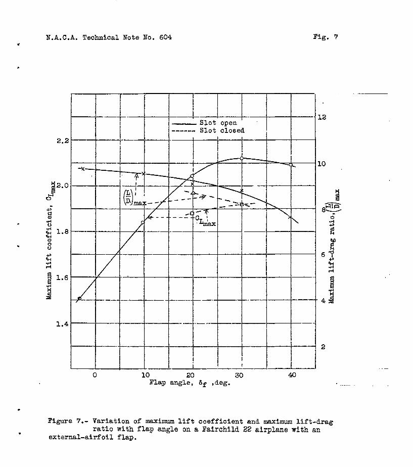
The characteristics of .the external-airfoil flaps are shown in figure 6. With increase in flap direction the angle of zero lift occurs at a larger negative angle, the slope of the lift curve remains essentially the same, and the angle for maximum lift is practically constant. Fig- ure 6 shows that the, slot between the main wing and flap appreciably increases the slope of the lift curve, the maximum lift coefficient, and the maximum ratio of lift to drag.
The nraximum lift coofficiont (fig. 7) increases with 'flap daflaction from 1.51 with the flap up to 2.12 with a
flap angle of 30°. The coeffioienf at larger flap angle8

H.A.C.A. Technical Note No. 604 5
is less, owing to a gradual closing of the'slot as is in- dicated from the curves of figures 6 and 7,
-- Figure 8 shows the scale effect on the minimum drag
coefficient. The coefficient decreases normally wfth in- creasing Reynolds Humber.
A comparfson of the rolling-moment coefficients (fig. 9) shows very little change in rolling moment with either flap angle or angle of attack. The adverse yawing moments become greater as the angle-of attack or flap angle is in- creased except &t the high angle of attack, 15.2 , where the flap angle has little effect on the yawing~mqments.
Performance Computations * - . The effect of the external-airfoil flaps on the per-
formance of the Fairchild 22 airplane was computsd frbm the data obtained in the full-scale tunnel'in order to re- duce tho amount .of flight testing required. 'It should bo appreciated that comparisons made on the basis of these computations show the manner in which tho perfo'rmanco is affected but do not represent the true performance of the airplane because, in particular, the tail surfacesTiere not in place when the tunnel tests wer.e made and,the horse- pomer-available curve used was only approximate. 1
Gliding performance.- The r,esults of the computations for gliding flight are presented in figure 10. The prin- cipal items of interest regarding the performKnee shoti by the fdgure are given in the following table. The tabi% also contains data for the airplane fitted mi.f;h ati N.A.C.A. CYH wing, which has been used as the basis for comparison with wings of the series previously tested. Under l'Equal diSpOSabl8 load,lI allomance has bean mXde for .the increased weight of the tving with the external-airfoil flaps.
- Powor-on performance,- Results of cdmputations of the
power-on performance are presented in figure ii. The com- plete power-requfred curves-for different defleCtibn8 of the flap are based on mind-tunnel data obtained at an air speed of 58 miles per hour. Because of the scale effect on the aerodynamic characteristics, a portion of the pOm8r+ required curve for the flap-up'(-3.2') condition at test speeds corresponding to maximum flight speed is.also given.
-

O.?C, external- airfoil
flap
-i--- l Ylnimm speed
Weight--
-.-J-----
Flap down (29.8O)
1m.p.h.)
41.1
I I I.A.C.A. CYaequal l,M>D 50.6 . . . . gross weight /
I ,
* L
inimum lidlzg angle (deg.)
5.9
5.4
5.4
i
Gliding angle at minlmnm speed
---f--- 7.5 9.9
I I I
i 7.4 . . .
1
7.4 . . .
I .
-- iIorfsonta1 distance
Itraveled during lObfoot descent
it.ximum I Minbml lap -3.2' flap 29.8'
(ft.1 o-t.1
968 /
573
1,058 ’ I-
770
----f-- 1,058
j 770
. .
l .

N.A.G.A. Technical Note No. 604 7
The principal performance characteristics shown by the figure and comparative data for the airplane fitted with tho N.A.C.A. CYH wing are given in the following table.
Wing
0.2oc, external- airfoil flap
N.A.C.A. CYH equal gross weight
N.A.C.A. CYH equal disposable load
Weight
1,600
1,600
1,535
Maximum :ate of climb
:ft. per min.)
535
594
624
-I--
Maximum angle of climb
(deg. >
5.5
5.8
6.4
--
-
1
(
I-
--- Eigh speed Icorrected for scale effect] (m.p.h.)
109,6
110,6
110.7
The preceding tables show the effect of the external- airfoil flap on the performance of the airplane'mdmay be briefly summarized as follows: The gliding performance is improved by use of the flaps; the climb is decreased, pri- marily because of the greater wing weight; the high speed is 1 mile per hour less than with the CYH wing.
FLIGHT
Teats
The flight tests were made to determine the effect of the flaps on the low Speed and on the take-off and landing characteristics. Flight measurements were also ma-de. to determine the effectiveness of the flaps when used as ai- lerons and tho stick forces required to operate them. Tho test procaduro, except whore noted in the text, was the

8 N-.A.C.A. Tochn .cal Note No: 604
same as that used in previous tests of--t-his series (roford cnces, 1 and 2).
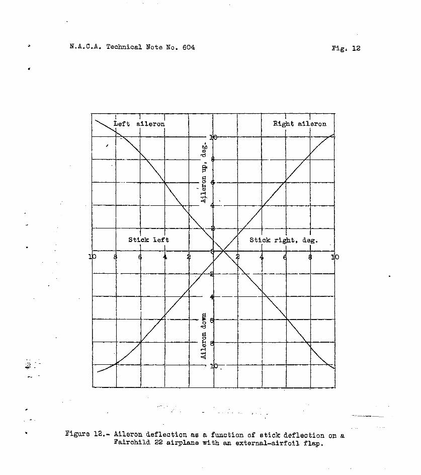
For the flight tests a $10' angular displacement of the oxtornal airfoils was found'to bo sufficfont for lat- eral contrbl, thus permitting a maximum flap dofloction of 27.4' from thc'main wing chord. The dofloction of tho fir,? c, when used for lateral control, is plotted against stick position in figure 12.
Besults and Discussion
hJaximum lut coefficients.- Inasmuch as the wind- -- tunnel tests mere made of the airplane with the horizontal tail surfaces removed, measurements of the maximum lift coefficients were made in flight, The results of these measurements are given in the following table., lcr com- parison the lift coefficients obtained from the tunnel tests ire also given.
---a--- ----
Flight:
Power off
Power on
Full-scale tunnel:
i?o horizontal tail
Tail correction applied
--em " ..------
In accordance'nfth Cho
- Flag
deflection
(deg. >
-3;2 46.8 1.60 27.4 41.3 2.06
-.3,2 41.3 2.06 27.4 35.2 2.84
-3.2 27.4
-2.2 27.4
-- .
1.47 2.02
previous tests of this rceries, t%e lift coefficients obtained in flight are somewhat higher than those obtained in the full-scale nind tunnel. With the flap up the maximum lift coefficient obtained in
v min'
(m.p.h.1
CL nax n
.
1.51 2.12

N.A.C.A. Technfcal Note MO. 604 9 r
flight exceeds that obtained in the tunnel by 8.8 percent. With the flap down the lift coefficient in flight is 2.0 percent higher than in the tunnel. An fnvestigation being conducted at the present time indicates that the discrepancy is due partly to the fact that fn flight the maxfmum lift coefficients were obtained by slowly increasing the angle of attack; Thereas in the tunnel, measurements mere made with the wing stationary. --* .
characteristics.- Take-off Figure 13 shows the effect of flap position on the ground run and on the distance re- quired to attain a height of 50 feet in a take-off. The values geven for the take-off distances apply to still-air conditions, in which the afrplane leaves the ground at 5 miles ger hour in excess of the full-throttle stalling -~ - speed for the given flap setting and in which this speed is maintained constant throughout the climb.
The method used in previous take-off tests was revised to-,sone extent for the present tests in order to improve the nrecfsion of the results. One of the chief difficult ties previously experienced was that comparative take-off runs are difficult to obtain because it is practically fm- possible for the pilot to make a take-off at exactly the spec4fied speed in each run and to hold that speed during the initial climb. Both of these items are impprtant, the
% air spood at the instant of take-off being particularly so because.it critically affects the ground run and also in- fluences the distance required to cl&m> to an altitude of 50 feet. The prfncipal change in procedure was that, in the present investigation, the ground run corresponding to a given take-off speed was determined from data obtained in a series of tests separate from those in which the air runs were measured. A description of the procedure for the take- off tests follons.
In the determination of the ground run the airplane was held by the brakes until steady full-throttle engine speed was obtained. The brakes mere then released and the tall mas raised as soon as possible. The fuselage was held horizontal until the.airplane had reached a speed I.0 to 15 miles per hour above the full-throttle stalling speed for the given flap setting. Tho motion of tho air- plane during tho run was recorded with a phototheodolite and, from the records, curves of speed against ground run Nero detorminoa. These results were corrected to fero wind. Check runs gave consistent results. The ground runs co+ responding to s;?ceds 5 mfles per hour in excees of the
. .

10 N.A.C.A. Technical Note No. 604
full-throttle stalling speed f-or any given flap setting were taken directly from these curves*
The air runs mere 'made in a manner similar to that of previous investigations. The separation of the air runs from the ground runs elfminated the need for considering the ground surface from which the take-offs mere made, a practiasl advantage that was due to the fact that the con- crete ramp used for the ground runs is available only for limited seriods of timer A-large number of runs were made so that it was possible to select only those in which the take-off speed was that specified and in tvhich the varfa- tion of speed during the climb mas small.
The results of-the measurements as given on figure 13 show that the flaps were effecttve only in reducing the ground run. The minimum ground run was 285 feet Of = 2'7.4') as compared mith 355 feet mfth the flap upa Thts decrease of 85 feet in the ground run represented a de- crease of 8.5 percent in the total run required to attain a height of 50 feat.
Landingsharacteristias.- ---I- Figure 14 shows the effect of the externaldairf-oil flaps on the distance required to lad from a height of 50 feet in still air and also on the ground run required after landing when a normal amount of braking is, appplied. The fla?s reduced the air run from 600 to 250 f=et., or approximately 60 percent. Even with the flaps up, homeirer, the air run was about 20 percent less than with the standard wing, With the flaps down, the air run ras about the same as those obtained with this airplane equipped with the previously tested flapped mings. The groun.d run was reduced from 335 feet to 280 feet, or 15 percent, owing primarily to the decrease .in landing speed from 48 to 43 miles per hour. The,flaps, therefore, are responsible for & decrease 1n the total landing run from 927 to 480 feet, or 48 percent.
Lateral-control characteristics.- The results of the ---- 1-p tests to determine the lateral-control characteristics of the external-airfoil flaps when they. were deflect-ed as ai- lerons are presented i,n figures 15 and 16. Maximum angu- lar velocity and acceleration are plotted against aileron deflection for the two extreme flap positions (fig. 151, and show that the rolling action sue to the external- airfoil flap increases uniformly with aileron displacement. , In figure LG th,e maximum angular velocity and acceleration e in roll obtained with abrupt full-right displacement of "

.
B.A.C.A. Technical Note Ho. 604 . 11
the control stick are plotted as functions of afr speed. The maximum rate of roll ,?nd the maximum acceleration in roll obtained with tho flap either up or down are consid- erably greater than with the standard ailerons for this airglnne (roferonce 5).
It will be observed from figure 16 that at any given speed the maximum rate of roll is less with the flap down than it is with the flap up, whereas the maximum angular acceleration is larger with the flap down. A possible ex- planation of this apparent inconsistency is the effect of the adverse or negative yaw with the flap down. In figure 17, which shows rates of roll and yaw against time for the two extreme flap positfoas, the difference in txe tiaarac- ter of the yawing action can be noted. (Magnitudes are not strictly comparable owing to the difference in speed.) With the flap up the yawing velocity is slightly positive at first and does not become negative until after the at- tainment of maximum rolling velocity. With the flap down, however, the yawing velocity is negative from the start and is of an appreciable magnitude before t-he attainment of maximum rate of roll. It seems possible that the rolling moment due to this negative yawing velocity may be of auf- ficfent magnitude to account for the apparent discrepancy between the relative magnitudes of angular velocities and accelerations for the two flap positions.
Another characteristic of the functioning of the con- trols shown by figure 17 is that the rolling motion starts almost immediately after the controls are deflected :or, in . other words, these ailerons have no appreciable lag.
The yawing action as observed by the pilot was adverse for all flap positions. With the flaps up, it was small and not objectionable. As the flaps were deflected, how- ever, the adverse yaw increased and was considered to be of objectionable magnitude"vith the flaps full down. The stick forces required to operate the axtornal-airfoil flaps as ailerons were considered by the pilots to be too hfgh for an airplane of this size. Tho forces for full aileron deflection were shown by measurement to be 12 and 20 pounds with the flaps up at 60 and 90 miles per hour, respeetive- lY* With the flax, down at speeds of 50 and 70 miles per hour, stick forces for full deflection were 11 and 15 powas.
These stick forces could have been reduced by increas- ing the stick travel but they would still be undesirable

3.2 . .
N.A.C.A. Technical Hoto No. 604
in that-they increase more rapidly tvith speed than do tho stick forces for normal ailerons,
CONCLUSPONS
I. The aerodynamic characteristics of the external- airfoil flap differ from those of split or plain f-laps principally in that the maximum lift is attained with less deflection of the flap (SO') and, in general, the L/D ratio is greater for a given lift increment.
24 The maximum'value of the lfft coefficient obtafned from the wind-tunnel tests is 1.51 with ,the flap in tLe minimum-drag position and 2.12 with th-e flap‘ deflected 30’. .
.
3. Prom flight tests it was found that the use of flaps decreased the minimum speed from 46.8 to 41.3 miles per hour, reduced the take-off run required to attain a height of 50 feet from 820 to 750 feet, and reduced the landing run from a height of 50 feet from 930 to 480 feet.
4. ' For a given aileron deflection there is very lit- tie change in rolling moment with either flap angle or
.
angle of attack, and the rolling action found in flight ma5 saCisfacCo.ry. 4
5. The 1256 of external-airf-oil flaps as ailerons is -* considered unsatisfactory because the stick forces required to operate them a5 ailerons increase too rapidly with speed and because the tidverse ya&vith..the flaps down is too large..
Langley Memorial Aeronautical Laboratory, Xationnl Advisory Committee for Aeronautics,
Langley Field, VQ., July 8, 1937.

X.A.C.A. Technical Note Bo. 604 \
13
REFERENCES
1. Dearborn, 0. H., and SoulB, H. A.: Full-Scale Wind- Tunnel and Flight Tests of a Fairchild 22 Airplane Equipped with a Fowler Flap. T.N. No. 578, N.A.C.A. 1936. .-
2. Dearborn, C. H., and Soul&, H. A.: Full-Scale Wind- Tunnel and Flight Tests of a Fafrchfld 22 Airplane Equipped with a Zap Flap and Zap Ailerons. T.N. No. 596, B.A.C.A., 1937. - :-
3. Platt, Robert C., and Abbott, Ira He: Aerodynamic Characteristics of H.A.C.A. 23012 and 23021 Air- foils with 20-Percent-Chord External-Rfrfoil Flaps of N,A.C.A. 23012 Section. T.R. No. 573;N.A+%~., 1936r
4. DeFrance, Smith J.: The N.R.C.A. Full-Scale Wind Tun- nel. T.R. No. 459, N.A.C.A., 1933.k
5. Soul&, H. A., and XcAvoy, W, H.: Flight Investigad tion. of Lateral Control Devices for Use with Full- Span Flaps. 'P.R. Bo. 517, B.A.C.A., 1935,

14 N.A.C;A. Technical Note 80~ 604 .
TABLE I .
FAIRCHILD 22 AIRPLUTE WIT-EE EXTERNAL-AIRFOIL FLAP
I (Flight Condition) ' '
Wing:
Area (mini + flaps) . . . , . . . ., ll(rl sq. ft, Span (II) . . . . . . . , , . . . . 32 ft. 10 In. - Chord (cm) . . . . . . . . . . . . 5 ft. 6 in. Aspect-ratio Airfoil section'
, . . , . . . . . ...6.31
Angle of wing settin; .*.'.'. . . . . N.A.C.A. 23015
. ,.. 3.2' Dihedral . . . . . . . *. -. :'. . . 0
Flap:
Area . . . . . . . . . . . . Span (a-foot cut-iui *Lt- tinter).. .
26 s& ft. 31 ft. 4 in.
Chord (cf) . . . c . : . . . . . . 11 in. Airfoil section . . . Flap deflection ril.it;v;! io'wing
Clark Y
chord . ..a .,. . : . . . . . . Up -3.20
Aileron deflection for all flap . Down 27.4'
positions . . . . . . . . . . . up loo Down 10'
Stabilizer:
Area. . . . . . . , . . . . . , . 27 sq. ft. Span . 10 ft. DeflecEi~n'(~eiati~e'to Chiuit'a;ii) Up 4.1'
Down 2.5'
Elevator:
Area . . . . 10.4 sq. ft. Deflectioi irilit;vi io'tir;st axis) Up 28'
Down 27' Distance from leading edge of wing
to elevator hinge . . . . . , . . 15 ft. 9 in.
Fin : Aroa , . . . . . , . . . . . . . . , 4.1 sq. ft.
.
.

N.A.C.A. Technical Not.0 80. 604 15
TABLE I (Cont.)
Rudder:
Area . . . . . . . . . . . . . . . . 6.0 sq. %t. Deflection . . . . . . . . . . . . Eight 20
Left 20'
Weight data:
Weight . . . , . . . . . . . . . . 1,525 to 1,575 lb. cmga position: back of leading
edge of wing 1 ft. 25 in. or 22 percent cw .
below thrust axis 0 ft. 5/8 in,
Engine: &cylinder inverted air-cooled Cirrus.
Bated horseporrer . . . . . . . . . 95 at 2,100 r.p.m. .- 1

N.A.C.A. Teohnkal Mte lo.604 Y -lO'O"- 7
Bigs.l,2
Figure l.- Three-view drswing of
Fairchild airplaae eqyipped with an exter~-airfoil
flap.
-w 0273 +) + b 1.82"(0.165 cf)
I.A.O.A. 23015
Figure a.- Saational view of wing ehowing loostion of external-airfoil flap
-

Bienre a.- Fairchild 22 airplane with erternd-airfoil flap.

l N.A.C.A. Technical Note Bo. 604 Pig. 4
10
-20
-
-
,-
-10 0 10 20 Right aileron, Beg- .
Figure 4.- Aileron deflection relative to flap setting for three settings of the flap. .

.4
17-f -1 --
.e .z
0 - 0 I’
I
Ii I v I I I I &W -.a ' Tss
A! Ra.
-
.
I I I I I I I I I I 1 , -la -u 4 0 4 a -- ia l6 a0
ugle of haOr of thrust rxls. cq , deg.

I
.U.A. Techaid Xots Ito.- I.A
I
_-
rigure 6.- Effeot of olooing rlot between wing M flap on the aerodyaado hlrohlld Sa slrplme eith aa rrternal-aLrfoll flap
cbrrrotrrlatlor of 8
N.A.C.A. Technical Note No. 604 w
Fig. 7
2.2
J 2.0
D --I - . zb=-L .‘I- --k-l--l
0 10 20 30 40 Flap angle, 6f ,deg.
10
Figure 7.- Variation of maximum lift coefficient and maximum lift-drag ratio with flap angle on a Fairchild 22 airplane with an
external-airfoil flap.

3 Bey?lolds Mumber ~ I I I I 5X10⁶
3 110 Test air 6peed. m.p.h. 2
Fi@=e 8.- Scale effect cut the minimum drag coefficient of a Fairchild 22 airplane with an external-airfoil? flap. 6f = -3.20. m

1.A.O.A. Teohnioal Hots PO.534 II
F1g.S (a) i
L
l
-’
*
I. I\ I I I I \
7.10
6 ; .oa g
Flgurr Q(a).- The sffeot of the flap used ar ailrroam on the rolling- and yati -1YF.
moment oo~ffiolant8 of Ptirahud aa rirpbno ulth an rxtrrorl-rlrfoil flap. aT'

S.A.O.A. Tsc~oal Hote Ho.604 Fig.9 b)
.
I 4
l
.
.
f
-.04
. -.oe
-.oe
-.lO
d j .02 % "0 5 :: 0 c) % P
I? 502 f pl!
Figure S(b).- The effect of the flap used 3s rilorons on the rolli -. of a Fairchild 2a airplane with an sxtemal-airfoil 3
- and yavlq- m~er.f cjeificientr np. OLT- 7.?O
-7 .-

SAOA. Technics1 Hate 110.804 mfg.9 (c)
/ .
.
7 + -.08 I
(Stiak rinht) -Anxle between rilerome. da=.- Qure B(o) .- The effeot of the flap used a~ rilerons on the rolling- srd yaning+ownt corfflolenta
of a Palrohild aa airplanr tith an rrtrrnal4rfoll flap. dr = - lB.@ 'L-J
4 *.
.

Horizontal velocity, m.p.h. 60 70 80 90 100
Velocity along flight path,n.p.h.- “CFliae-p&h angle
Figure lO.- Velocity diagram of a Bairchild 22 airplane with an external-airfoil flap.
\

I , I
. 1 0 c
30
a
-..- - w effact.
il!zE- 4 50 60 70 80 90 100 I.10
Air speed, m.p.h. Fignre Il.- Horsepower curve8 of a Fairchild 22 airplane with an external-airfoil flap.
I I I I
-Data from tunnel tests at 58 m.p.h.
- ---Corrected for scale
Y ii- .
E
_.
-. . _
+ _
co .
,
.
N.A.C.A. Technical Note No. 604 Pig, 12
, I I I I I Left aileron Right aileron
.
.-- --
r
Figure. 12.- Aileron deflection as a function of stick deflection on a birchild 22 airplane with an external-airfoil flap.

N.A.C.A. Technical Note No. 604 Fig. 13

c . . t
0 100 300 400 600 700 800 900 l.CJW Borieontd distance, ft. 4
Figure 14.- Landing curve8 of a Bairchild 22 airplane with an external-airfoil flap. k .

1.0
.2
0
I I Ii.1 I Maximum deflection--Id 1
I d/=4--- ---- I
1’
I’I 4 8 12 16 20
Angle between ailerons, deg.
20
. . . .
16
0 0 kl # .
Figure 15(a).- Variatiomof control characteristics with aileron deflection of a Fairchild 22 airplane with an external-airfoil flap. i?lap ~~(-3.2~); test air speed, 69 m.p.h. s
x

L I ,
4 8 12 16 20 Angle between ailerons, deg.
8 16
0 0
Figure 15(b) .- Variation of control charact.eristI.ca with aileron deflection of a Fairchild 22 4 airplane with an external-airfoil flap. Ilap aom(27.4O); test air speed, 57.5 it .
. 1

. L . I I
* 4 .
1 ! I I - - Fiap down (27.4'>
I i .I -- I
.B
j .
” 70 80 90 100 110 120 II.30 140
Air speed., ft. per sec. e
Figure 16.- Variation of rate of roll and angular acceleration in roll with air speed of a Bairchild 9 22 airplane with an externaLairfoil flap.
iit

‘N.A.C.A. Technical Wota Xo. 604 Pig. 17
i
---t-t+* I I \I 1
--.-
1 I . I ’
. -. I
I 0 -0 c