no part builder required: creating custom parts for...
TRANSCRIPT

No Part Builder Required: Creating Custom Parts for
Pressure Networks in Autodesk® AutoCAD® Civil 3D®
Brian J. Hailey, P.E. – CAD-1
CI1472-L
Sure, Autodesk AutoCAD Civil 3D software comes with a lot of parts for utility modeling, but what if you have a unique situation or your municipality uses a specific part that doesn't ship with the product? Civil 3D comes with tools to assist you in quickly creating that new part and getting back to design instead of spending hours and hours just trying to figure out what a work plane is in Part Builder and what you do with it.
Learning Objectives At the end of this class, you will be able to:
• Explain the file structure of the pressure network catalog
• Create the necessary drawing files for importing into the catalog
• Create a new pressure network catalog and import parts into it
• Create a pressure network parts list using the newly created catalog
About the Speaker
Having graduated from Colorado State University with a Bachelors of Science in Civil Engineering, Brian
worked as a design engineer for 8 years in a couple of general civil engineering firms. Focusing primarily
on the land development side of things he became a Licensed Professional Engineer in the State of
Colorado. Currently, Brian is a Technical Specialist with CAD-1 where he assists engineering companies
(as well as governmental agencies) with implementing Autodesk software (e.g. AutoCAD Civil 3D). Brian
has taught at Autodesk University 6 times, once receiving the award for "Best Unconference" and won
the overall AUGI Top DAUG competition at AU2011.
No Part Builder Required: Creating Custom Parts for Pressure Networks in Autodesk® AutoCAD® Civil 3D®
2
Introduction
Autodesk AutoCAD Civil 3D comes with several pressure part catalogs and each one has
several parts in them but often times what’s provided out of the box won’t work for a particular
situation. At times like this, a current part that’s close can be used or a new part can be created.
If you’ve ever used the Part Builder tools that come with Civil 3D you know that they are not
very user friendly and can be somewhat picky at times. The new Pressure Networks that were
introduced in Civil 3D 2013 have a much easier and user friendly way of creating pressure
parts.
One thing to note about the tools and commands that will be presented here, technically, they
are undocumented commands. This means they are not in the help files that come with Civil 3D.
Instructions for using these tools can be found at "C:\Program Files\Autodesk\Autodesk
AutoCAD Civil 3D 2014\Sample\Civil 3D API\Part Publishing
Wizard\PartPublishingWizardUsersGuide.docx" (assuming Civil 3D is installed in the default
location). This guide is a good way to get started but it doesn’t go into details on the settings or
some best practices that will be covered in this class.
Explain the File Structure of the Pressure Network Catalog
Prior to working with a new catalog, the drawing must have the catalog that contains the parts
set as the current catalog. If there are several users that will be accessing the catalog it’s
recommended to place the catalog on the server where everyone can access it. This way, if a
change needs to be made, simply changing the one catalog changes it for all users.
File Structure
The pressure network catalog uses multiple files. The primary file is a .sqlite file (ex.
“Imperial_AWWA_Mechanical.sqlite”). Each catalog also has a folder of supporting files. The
folder has the exact same name as the .sqlite file but without the extension (ex.
“Imperial_AWWA_Mechanical”).
Set the Catalog
To set the catalog you must first be in the drawing where the parts will be used. The catalog
location is stored in the drawing (and can be set differently for different drawings). If the catalog
can’t be found you will receive this message when setting a parts list that references the missing

No Part Builder Required: Creating Custom Parts for Pressure Networks in Autodesk® AutoCAD® Civil 3D®
3
catalog:
In the drawing that will be using the catalog, expand out the Create Design panel on the Home
tab of the ribbon and choose, “Set Pressure Network Catalog”.

No Part Builder Required: Creating Custom Parts for Pressure Networks in Autodesk® AutoCAD® Civil 3D®
4
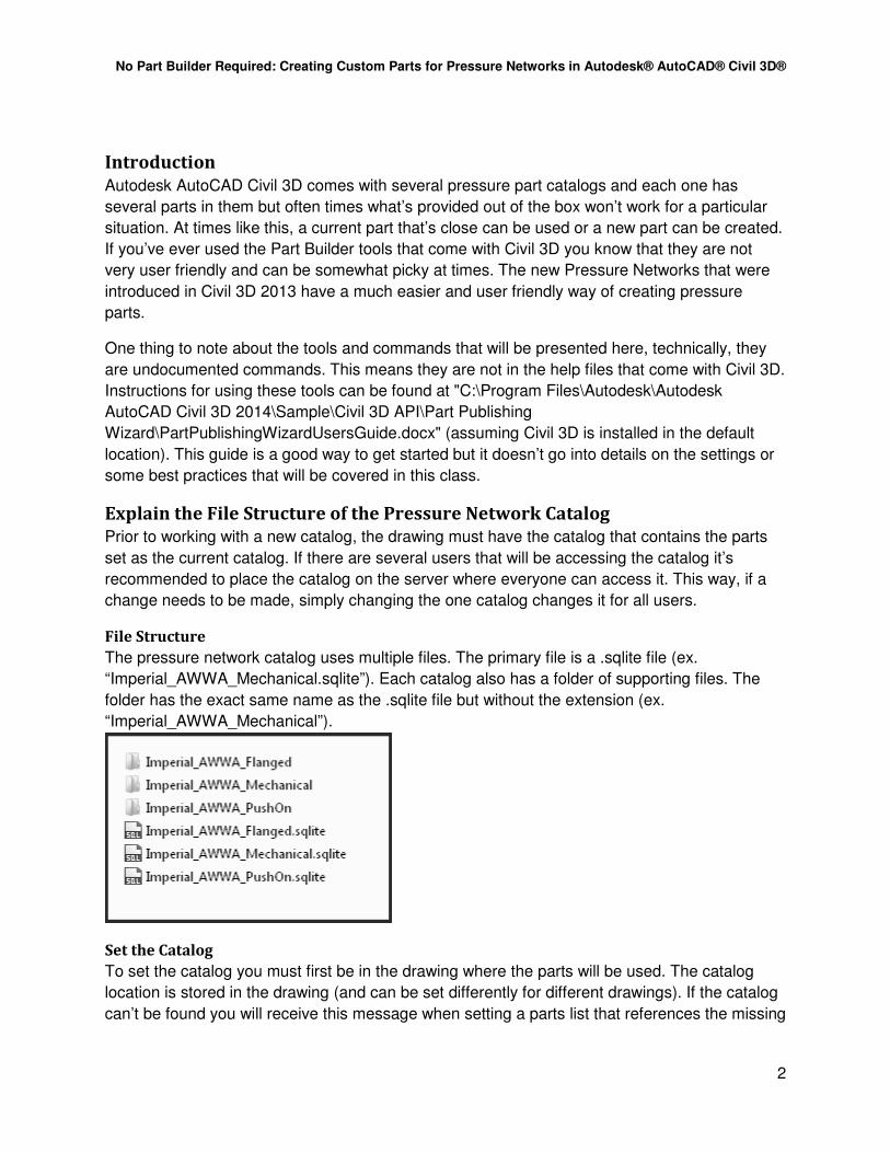
In the “Set Pressure Network Catalog” dialog box, use the folder icon to browse to the location
of the catalog. This should be the folder the .sqlite file is in and not the supporting folder for the
catalog.
Exercise
1. Create a New Drawing
• From the Application Menu (big blue “A” in the top left of the Civil 3D application) select
the New command.
• Browse to the folder containing the dataset ("C:\Datasets\Wednesday\CI1472-L\") and
choose the template “No Part Builder Needed.dwt”.
2. Set the Catalog
• On the Home tab of the ribbon, expand out the Create Design panel and choose the Set
Pressure Network Catalog command.
• In the Set Pressure Network Catalog dialog box, select the folder icon to browse to the
location of the catalog.
• Browse to the location of the class catalog file: " C:\Datasets\Wednesday\CI1472-L\"
No Part Builder Required: Creating Custom Parts for Pressure Networks in Autodesk® AutoCAD® Civil 3D®
5
• From the Catalog database file: drop-down, choose
“Imperial_AWWA_Mechanical.sqlite”.
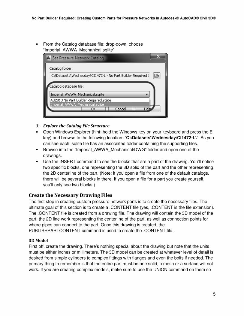
3. Explore the Catalog File Structure
• Open Windows Explorer (hint: hold the Windows key on your keyboard and press the E
key) and browse to the following location: “C:\Datasets\Wednesday\CI1472-L\”. As you
can see each .sqlite file has an associated folder containing the supporting files.
• Browse into the “Imperial_AWWA_Mechanical\DWG” folder and open one of the
drawings.
• Use the INSERT command to see the blocks that are a part of the drawing. You’ll notice
two specific blocks, one representing the 3D solid of the part and the other representing
the 2D centerline of the part. (Note: If you open a file from one of the default catalogs,
there will be several blocks in there. If you open a file for a part you create yourself,
you’ll only see two blocks.)
Create the Necessary Drawing Files
The first step in creating custom pressure network parts is to create the necessary files. The
ultimate goal of this section is to create a .CONTENT file (yes, .CONTENT is the file extension).
The .CONTENT file is created from a drawing file. The drawing will contain the 3D model of the
part, the 2D line work representing the centerline of the part, as well as connection points for
where pipes can connect to the part. Once this drawing is created, the
PUBLISHPARTCONTENT command is used to create the .CONTENT file.
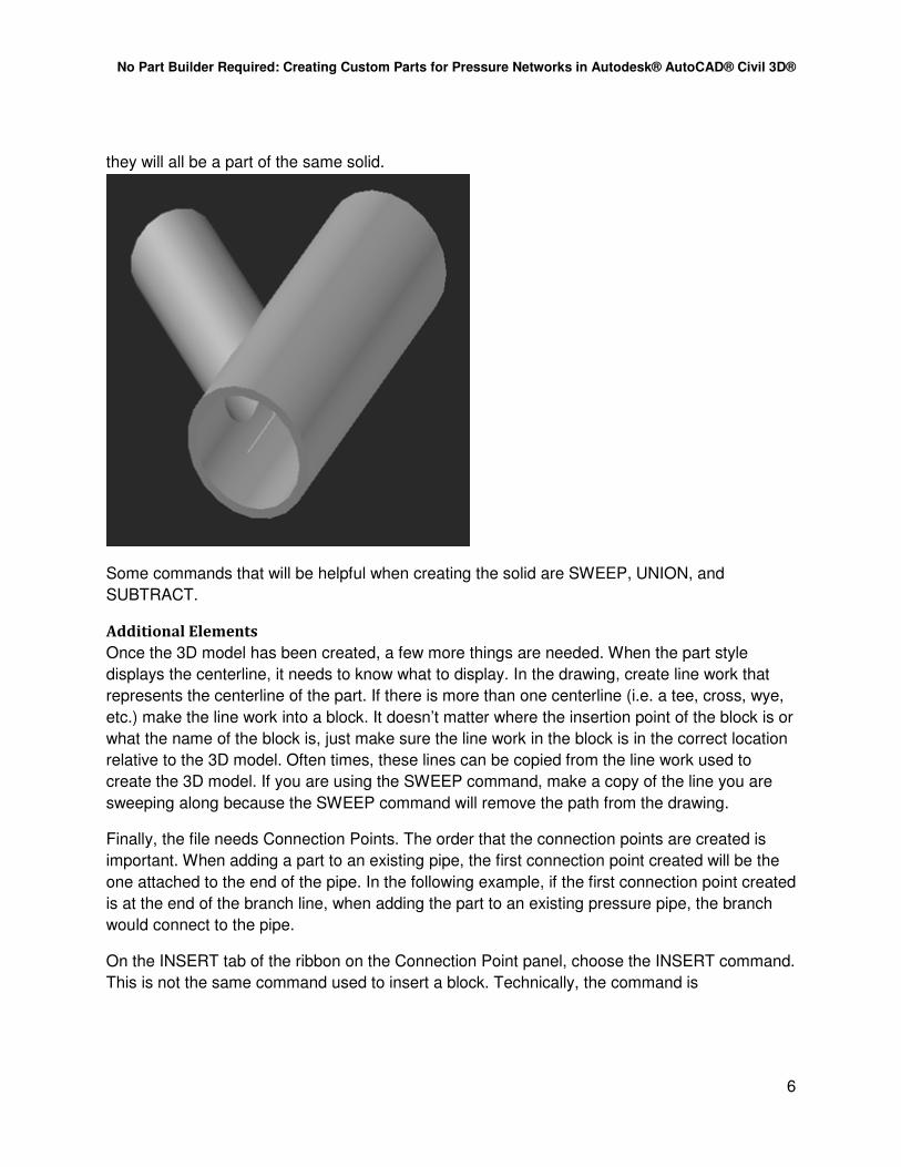
3D Model
First off, create the drawing. There’s nothing special about the drawing but note that the units
must be either inches or millimeters. The 3D model can be created at whatever level of detail is
desired from simple cylinders to complex fittings with flanges and even the bolts if needed. The
primary thing to remember is that the entire part must be one solid, a mesh or a surface will not
work. If you are creating complex models, make sure to use the UNION command on them so
No Part Builder Required: Creating Custom Parts for Pressure Networks in Autodesk® AutoCAD® Civil 3D®
6
they will all be a part of the same solid.
Some commands that will be helpful when creating the solid are SWEEP, UNION, and
SUBTRACT.
Additional Elements
Once the 3D model has been created, a few more things are needed. When the part style
displays the centerline, it needs to know what to display. In the drawing, create line work that
represents the centerline of the part. If there is more than one centerline (i.e. a tee, cross, wye,
etc.) make the line work into a block. It doesn’t matter where the insertion point of the block is or
what the name of the block is, just make sure the line work in the block is in the correct location
relative to the 3D model. Often times, these lines can be copied from the line work used to
create the 3D model. If you are using the SWEEP command, make a copy of the line you are
sweeping along because the SWEEP command will remove the path from the drawing.
Finally, the file needs Connection Points. The order that the connection points are created is
important. When adding a part to an existing pipe, the first connection point created will be the
one attached to the end of the pipe. In the following example, if the first connection point created
is at the end of the branch line, when adding the part to an existing pressure pipe, the branch
would connect to the pipe.
On the INSERT tab of the ribbon on the Connection Point panel, choose the INSERT command.
This is not the same command used to insert a block. Technically, the command is

No Part Builder Required: Creating Custom Parts for Pressure Networks in Autodesk® AutoCAD® Civil 3D®
7
AUTODESKCONNECTIONPOINT but the button on the ribbon simply shows INSERT.
There are really only two things that are necessary when inserting the connection point, the
location of the connection and the direction from which the pipe will be connecting to the part.
Once the command is run, it will ask you for the object to add the connection to (select the 3D
solid), where to insert the connection point (often times that will be the end of the lines used to
represent the centerline of the part) and then the direction of the connection. When specifying
the direction, simply pick two points in the drawing that are in the direction of the connection
(again, often times the centerline line work can be used to assist with this). Finally, Civil 3D will
ask if you would like to add engineering data to the fitting. As best I can tell, this is not currently
being used in this process. Perhaps some other program uses the same type of entity but no
matter which option is chosen, the command ends.
Once done, make sure the 3D arrow of the connection point is pointing in the correct direction.
When creating parts, the allowable deflection will be determined based on the direction of the
connection point.
Publish Part
Now that the required drawing with all the required components is created, it’s time to create the
.CONTENT file. Prior to publishing the part, make sure your drawing area is square. This is

No Part Builder Required: Creating Custom Parts for Pressure Networks in Autodesk® AutoCAD® Civil 3D®
8
important because the drawing area will be made into an image and if that image isn’t square it
will be distorted to fit a square and your part image will look odd.
An easy way to make your drawing area square is to start a new drawing, draw a circle (it
doesn’t matter what size), and zoom extents. Resize the AutoCAD window until the circle is
touching the top, bottom, left and right simultaneously.
Once that is done, close the drawing with the circle and go back to the drawing with the part. To
create a consistent look to the parts, set an isometric view using the View Cube.
The actual command to create the .CONTENT file is an undocumented command in Civil 3D. At
the command line, type PUBLISHPARTCONTENT. Watch the command line, it will show
exactly what to do:
• Select the 3D solid representing the part.
• Select the linework representing the centerline of the part (the solid will temporarily be
hidden).
• Specify the units of the model (again, the drawing must have been done in inches or
millimeters).
• Specify the part type.
Once this is all done, the drawing will be zoomed extents, the visualization style will be changed
to Shades of Grey, an image will be created of the solid, and a dialog box asking for the name
and location of the .CONTENT file will be displayed. Save the .CONTENT file and the process is
done. If desired, save the drawing file (it’s recommended but not required).
No Part Builder Required: Creating Custom Parts for Pressure Networks in Autodesk® AutoCAD® Civil 3D®
9
Exercise
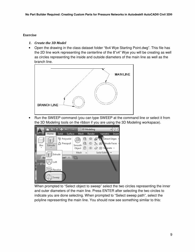
1. Create the 3D Model
• Open the drawing in the class dataset folder “8x4 Wye Starting Point.dwg”. This file has
the 2D line work representing the centerline of the 8”x4” Wye you will be creating as well
as circles representing the inside and outside diameters of the main line as well as the
branch line.
• Run the SWEEP command (you can type SWEEP at the command line or select it from
the 3D Modeling tools on the ribbon if you are using the 3D Modeling workspace).
When prompted to “Select object to sweep” select the two circles representing the inner
and outer diameters of the main line. Press ENTER after selecting the two circles to
indicate you are done selecting. When prompted to “Select sweep path”, select the
polyline representing the main line. You should now see something similar to this:

No Part Builder Required: Creating Custom Parts for Pressure Networks in Autodesk® AutoCAD® Civil 3D®
10
As you can see, the circles and lines used in the command are erased from the drawing.
This is why (as you might have noticed) there were two copies of the lines.
• Repeat the process for the branch line:
• Switch into a 3D view. You can either hold down the Shift key and the middle mouse
button or use the View Cube.

No Part Builder Required: Creating Custom Parts for Pressure Networks in Autodesk® AutoCAD® Civil 3D®
11
There are currently four cylinders in the file, one representing the outside diameter of the
main line, the inside diameter of the mainline, the outside of the branch and the inside of
the branch.
• Without having anything selected, run the SUBTRACT command. When prompted to
“Select objects:” select the two cylinders representing the outside diameters and press
enter. When prompted to “Select solids, surface, and regions to subtract..” select the two
inner cylinders and press enter. When done, you should see something similar to this:
NOTE: Use the SUBTRACT command on both the main line and branch lines at the
same time. If you don’t, the branch line will extend into the main line. Also note, if you
have a hard time selecting the inner cylinders, turn your selection highlighting on and/or
turn on selection cycling.
• To ensure the solids are all one piece, use the UNION command. Select the entire
model to join everything together. (Note: In this example, everything was already one
solid as a result of the subtract command but that is not always the case.)
2. Add the Connection Points
• Continue working in the same drawing as before.
• Switch to a South East Isometric view (you can use the View Cube, Shift+Middle Mouse,
or the in-canvas viewport controls).

No Part Builder Required: Creating Custom Parts for Pressure Networks in Autodesk® AutoCAD® Civil 3D®
12
This view is used because this end will be the first one to have a connection point added
to it.
• On the Insert tab of the ribbon (make sure the Civil 3D workspace is current), select the
INSERT command on the Connection Point panel.
• When prompted for the object to add the connection point to, select the 3D Solid.
• For the insertion point of the connection, snap to either the end of the line or the center
of the end of the 3D model (they should be at the same location).
• When prompted to pick the 1st point for the direction, select the opposite end of the line.
• When prompted to pick the 2nd point for the direction, select the end of the line at the
insertion of the connection point.
• The order to pick the points is shown in the image below:
• When prompted to add engineering data, select either Y or N (at this point, it doesn’t
seem to have any different effect either way you choose).

No Part Builder Required: Creating Custom Parts for Pressure Networks in Autodesk® AutoCAD® Civil 3D®
13
• Repeat the process for the other end of the main line and then the end of the branch
line. When completed, the drawing should look similar to this:
3. Make the Drawing Area Square
• Create a new drawing using the default template that ships with Civil 3D (use the QNEW
command).
• Make sure Civil 3D is not maximized (you’ll need to adjust the size of the application).
• Draw a circle (it doesn’t matter the size of the circle) and then Zoom Extents.
• Adjust the limits of Civil 3D so the drawing area is square. The circle should touch the
top, bottom, left, and right sides of the drawing area.
• Close the file with the circle in it.
4. Publish the Part
• Open “8x4 Wye with Connectors.dwg” from the class folder. (Note: This file is a bit more
detailed then the model created in the last couple exercises.)
• On the View Cube, click the South West corner to set an isometric view.
• Run the command PUBLISHPARTCONTENT.
• Select the solid representing the part.
• Select the block representing the centerline of the part.
• Choose the unit Inches for the Measuring Unit.
• Specify the part type as “Wye”.
• Save the .CONTENT file to the class location and give it the name “8x4 Wye with
Connectors.CONTENT”. (Note: If you get a message, “Error during Publish:
eWasErased”, the process still seems to work just fine.)
Create a New Pressure network Catalog and Import Parts
As mentioned before, the catalog is a .sqlite file with an associated folder containing .dwg files
and image files. Simply copying a catalog using Windows Explorer seems to work (if the catalog
No Part Builder Required: Creating Custom Parts for Pressure Networks in Autodesk® AutoCAD® Civil 3D®
14
needs to be renamed, rename the .sqlite file as well as the support file the same) but I haven’t
done much testing at all with it so verify the results prior to committing to a copied catalog.
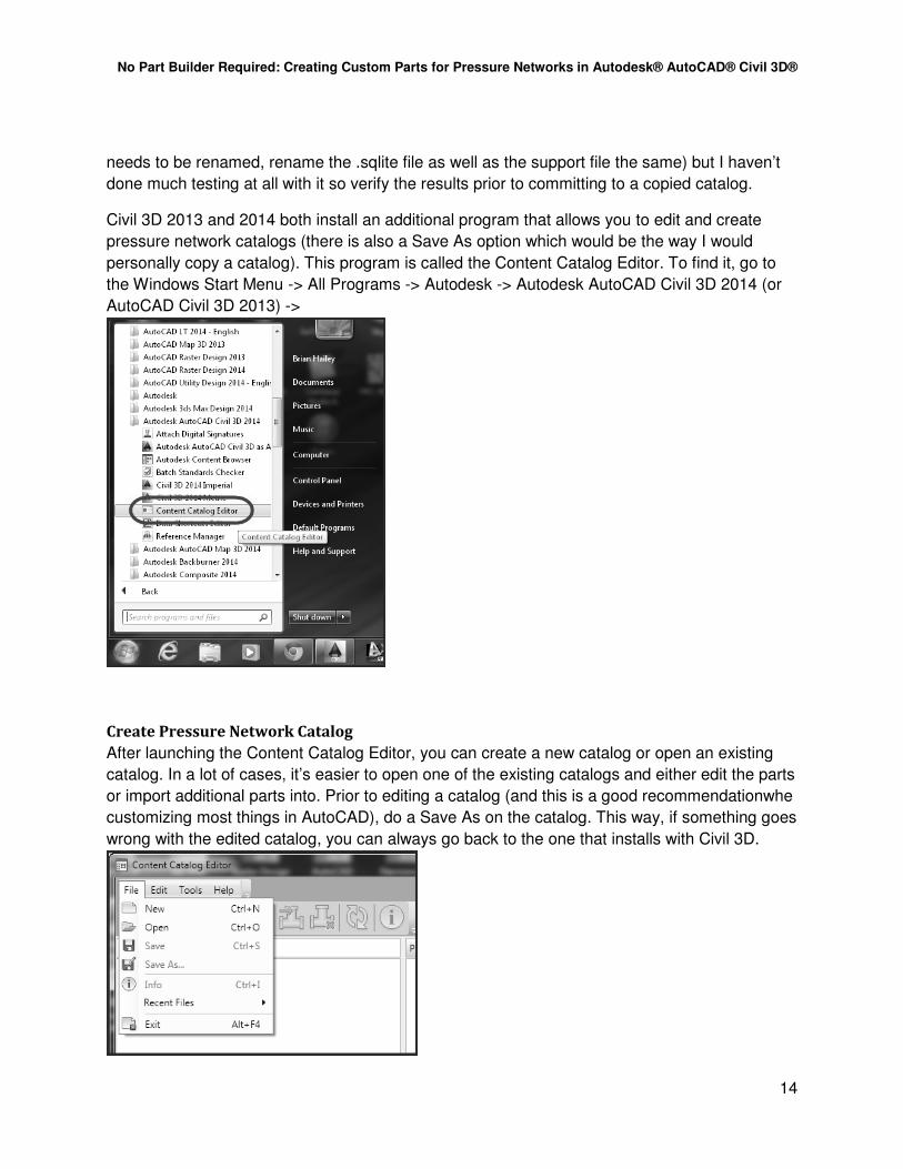
Civil 3D 2013 and 2014 both install an additional program that allows you to edit and create
pressure network catalogs (there is also a Save As option which would be the way I would
personally copy a catalog). This program is called the Content Catalog Editor. To find it, go to
the Windows Start Menu -> All Programs -> Autodesk -> Autodesk AutoCAD Civil 3D 2014 (or
AutoCAD Civil 3D 2013) ->
Create Pressure Network Catalog
After launching the Content Catalog Editor, you can create a new catalog or open an existing
catalog. In a lot of cases, it’s easier to open one of the existing catalogs and either edit the parts
or import additional parts into. Prior to editing a catalog (and this is a good recommendationwhe
customizing most things in AutoCAD), do a Save As on the catalog. This way, if something goes
wrong with the edited catalog, you can always go back to the one that installs with Civil 3D.

No Part Builder Required: Creating Custom Parts for Pressure Networks in Autodesk® AutoCAD® Civil 3D®
15
Import Parts
Once you have the catalog that you will be editing open (new one or an existing one), we will
import new parts into it. There are two methods of importing parts into the catalog, with and
without a .CONTENT file. To create a new pipe, import the part without the .CONTENT file. To
create a fitting or appurtenance, import the part with the .CONTENT file.
Import Pipe – Without .CONTENT File
To add a pipe to the catalog, use the option to import the part without. Open the catalog that the
new pipe will be added to in the Content Catalog Editors. On the toolbar, choose Import Part
In the Import Part dialog box, choose the option “Without .CONTENT file”
On the Part Type section, set the Industry to “Water”, the Part Type to “pipe” and specify a Part
Family Name. The Part Family Name is used to help organize the parts in the catalog. As far as
I can tell, it is not used within Civil 3D when specifying the parts for the parts list, or when adding

No Part Builder Required: Creating Custom Parts for Pressure Networks in Autodesk® AutoCAD® Civil 3D®
16
the parts to the model.
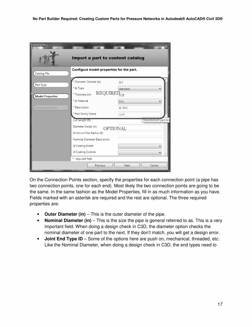
On the Model Properties section, fill out as much as you can (you don’t need to fill it out
completely). Any fields that are marked with an asterisk are required. The required fields and a
brief explanation of what they are and where they are used follows:
• Diameter Outside (in) – The outside diameter of the pipe. This is used to display the
outside of the pipe in the model.
• Id Type – This is how the inner diameter is related to the outer diameter. I’m not exactly
sure how this is used in the model. I typically use Standard for this value.
• Thickness (in) – This is the wall thickness of the pipe. It is used to determine the inner
diameter of the pipe.
• Id Material – The material of the pipe. This is used to organize your catalog.
• Description – This is a simple description of the pipe. It is used as the name of the part
when added to the parts list.
• Part Family Name – This is the same as what was entered in the Part Type portion of
the import command. It cannot be changed in this dialog.
The rest of the settings are optional but several of them will be used as the default settings
when adding the part to the parts list. They are as follows:
• Cut Length (ft) – How long is each section of pipe? This is used when having a pipe
follow a surface.
• Minimum Flex Radius (ft) – When curving a pipe by deflecting at the joints, what is the
minimum radius that you can place the pipe?
No Part Builder Required: Creating Custom Parts for Pressure Networks in Autodesk® AutoCAD® Civil 3D®
17
On the Connection Points section, specify the properties for each connection point (a pipe has
two connection points, one for each end). Most likely the two connection points are going to be
the same. In the same fashion as the Model Properties, fill in as much information as you have.
Fields marked with an asterisk are required and the rest are optional. The three required
properties are:
• Outer Diameter (in) – This is the outer diameter of the pipe.
• Nominal Diameter (in) – This is the size the pipe is general referred to as. This is a very
important field. When doing a design check in C3D, the diameter option checks the
nominal diameter of one part to the next. If they don’t match, you will get a design error.
• Joint End Type ID – Some of the options here are push on, mechanical, threaded, etc.
Like the Nominal Diameter, when doing a design check in C3D, the end types need to
No Part Builder Required: Creating Custom Parts for Pressure Networks in Autodesk® AutoCAD® Civil 3D®
18
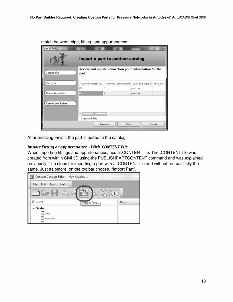
match between pipe, fitting, and appurtenance.
After pressing Finish, the part is added to the catalog.
Import Fitting or Appurtenance – With .CONTENT File
When importing fittings and appurtenances, use a .CONTENT file. The .CONTENT file was
created from within Civil 3D using the PUBLISHPARTCONTENT command and was explained
previously. The steps for importing a part with a .CONTENT file and without are basically the
same. Just as before, on the toolbar choose, “Import Part”.
No Part Builder Required: Creating Custom Parts for Pressure Networks in Autodesk® AutoCAD® Civil 3D®
19
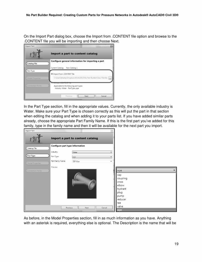
On the Import Part dialog box, choose the Import from .CONTENT file option and browse to the
.CONTENT file you will be importing and then choose Next.
In the Part Type section, fill in the appropriate values. Currently, the only available industry is
Water. Make sure your Part Type is chosen correctly as this will put the part in that section
when editing the catalog and when adding it to your parts list. If you have added similar parts
already, choose the appropriate Part Family Name. If this is the first part you’ve added for this
family, type in the family name and then it will be available for the next part you import.
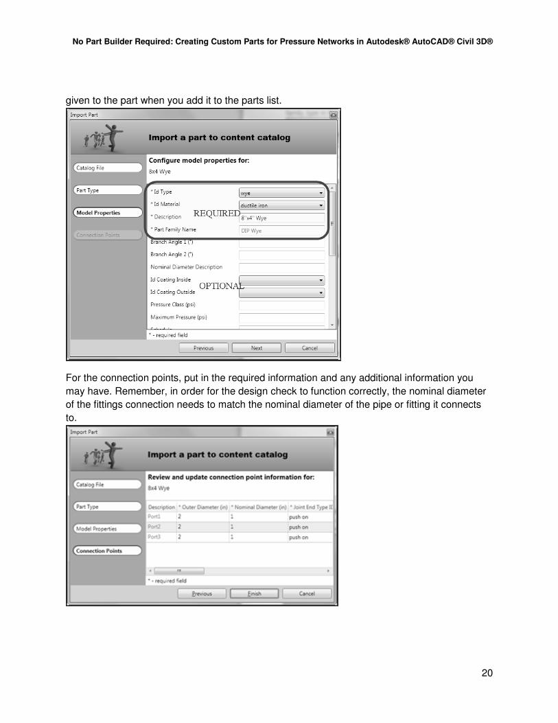
As before, in the Model Properties section, fill in as much information as you have. Anything
with an asterisk is required, everything else is optional. The Description is the name that will be
No Part Builder Required: Creating Custom Parts for Pressure Networks in Autodesk® AutoCAD® Civil 3D®
20
given to the part when you add it to the parts list.
For the connection points, put in the required information and any additional information you
may have. Remember, in order for the design check to function correctly, the nominal diameter
of the fittings connection needs to match the nominal diameter of the pipe or fitting it connects
to.
No Part Builder Required: Creating Custom Parts for Pressure Networks in Autodesk® AutoCAD® Civil 3D®
21
Exercise
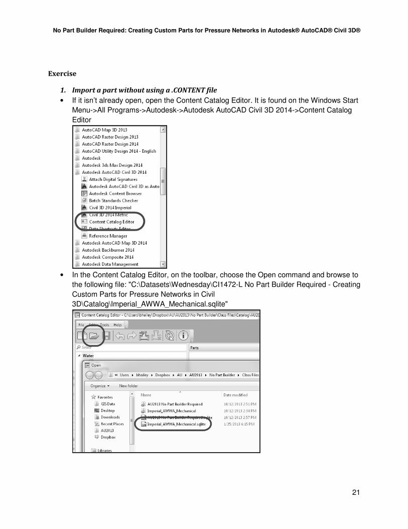
1. Import a part without using a .CONTENT file
• If it isn’t already open, open the Content Catalog Editor. It is found on the Windows Start
Menu->All Programs->Autodesk->Autodesk AutoCAD Civil 3D 2014->Content Catalog
Editor
• In the Content Catalog Editor, on the toolbar, choose the Open command and browse to
the following file: "C:\Datasets\Wednesday\CI1472-L No Part Builder Required - Creating
Custom Parts for Pressure Networks in Civil
3D\Catalog\Imperial_AWWA_Mechanical.sqlite"

No Part Builder Required: Creating Custom Parts for Pressure Networks in Autodesk® AutoCAD® Civil 3D®
22
• Once the catalog has been opened, choose Import Part from the toolbar.
• In the Import Part dialog box in the Catalog File section, choose “Without .CONTENT
file” and then click Next.
• In the Part Type section, choose “Water” for the Industry, “pipe” for the Part Type, type in
“PVC C900” for the Part Family Name, and then click Next. (Note: You may have to go
back and edit the Part Family Name to get all caps for “PVC”.)
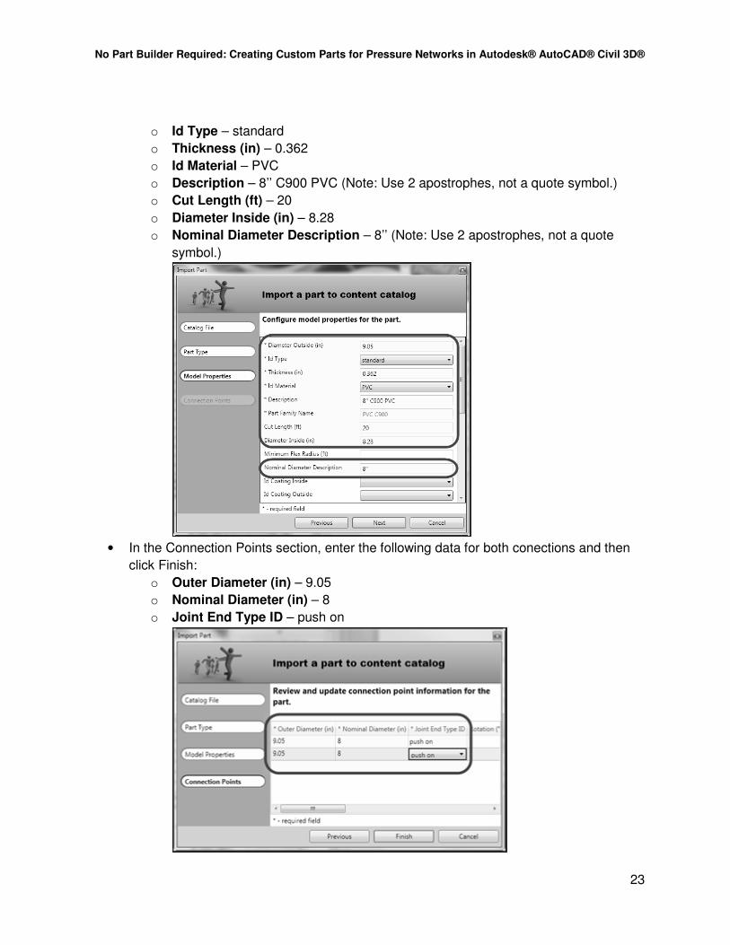
• In the Model Properties section, enter the following data and then click Next:
o Diameter Outside (in) – 9.05
No Part Builder Required: Creating Custom Parts for Pressure Networks in Autodesk® AutoCAD® Civil 3D®
23
o Id Type – standard
o Thickness (in) – 0.362
o Id Material – PVC
o Description – 8’’ C900 PVC (Note: Use 2 apostrophes, not a quote symbol.)
o Cut Length (ft) – 20
o Diameter Inside (in) – 8.28
o Nominal Diameter Description – 8’’ (Note: Use 2 apostrophes, not a quote
symbol.)
• In the Connection Points section, enter the following data for both conections and then
click Finish:
o Outer Diameter (in) – 9.05
o Nominal Diameter (in) – 8
o Joint End Type ID – push on

No Part Builder Required: Creating Custom Parts for Pressure Networks in Autodesk® AutoCAD® Civil 3D®
24
• In the Content Catalog Editor, review the part that was just imported.
2. Import a part using a .CONTENT file
• In the Content Catalog Editor, click Import Part on the toolbar.
• In the Import Part dialog box, choose “Import from .CONTENT file” and then click the
ellipsis (button with three periods…). Browse to the following .CONTENT file:
"C:\Datasets\Wednesday\CI1472-L No Part Builder Required - Creating Custom Parts

No Part Builder Required: Creating Custom Parts for Pressure Networks in Autodesk® AutoCAD® Civil 3D®
25
for Pressure Networks in Civil 3D\8x4 Wye.CONTENT" and then click Next.
• In the Part Type section, set the following values and then click Next:
o Industry – Water
o Part Type – wye
o Part Family Name – DIP Wye

No Part Builder Required: Creating Custom Parts for Pressure Networks in Autodesk® AutoCAD® Civil 3D®
26
• In the Model Properties section, set the following values and then click Next:
o Id Type – wye
o Id Material – ductile iron
o Description – 8’’x4’’ Wye (Note: Use 2 apostrophes and not a quote symbol.)
o Nominal Diameter Description – 8’’x4’’ Wye (Note: Use 2 apostrophes and not
a quote symbol.)
• In the Connection Points section, enter the following data and then hit Finish. The first
two connection points are along the main 8” line and the third connection point is for the
4” branch.
o Outer Diameter (in) – 9.05, 9.05, 4.80
o Nominal Diameter (in) – 8, 8, 4
o Joint End Type ID – mechanical, mechanical, mechanical

No Part Builder Required: Creating Custom Parts for Pressure Networks in Autodesk® AutoCAD® Civil 3D®
27
• In the Content Catalog Editor, review the part that was added to the catalog and its
properties.
• Save the catalog by pressing the Save button on the ribbon.
No Part Builder Required: Creating Custom Parts for Pressure Networks in Autodesk® AutoCAD® Civil 3D®
28
Create a Pressure Network Parts List
In order to use the parts that are added to the catalog, they must first be added to a parts list in
the drawing they will be used. Typically, they will be added to the template so that whenever a
drawing is created from the template the parts list is ready to be used. Different parts lists can
be created for different applications such as water vs. gas or even Ductile Iron water vs. PVC
water.
Create Parts List
Prior to creating the parts list, ensure the drawing is using the catalog that contains the parts
needed for the parts list. To set the catalog see page 2 for instructions.
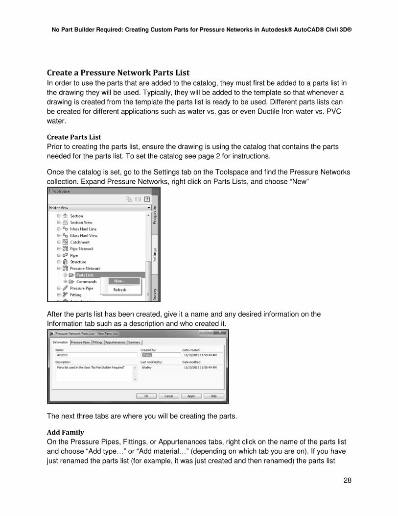
Once the catalog is set, go to the Settings tab on the Toolspace and find the Pressure Networks
collection. Expand Pressure Networks, right click on Parts Lists, and choose “New”
After the parts list has been created, give it a name and any desired information on the
Information tab such as a description and who created it.
The next three tabs are where you will be creating the parts.
Add Family
On the Pressure Pipes, Fittings, or Appurtenances tabs, right click on the name of the parts list
and choose “Add type…” or “Add material…” (depending on which tab you are on). If you have
just renamed the parts list (for example, it was just created and then renamed) the parts list
No Part Builder Required: Creating Custom Parts for Pressure Networks in Autodesk® AutoCAD® Civil 3D®
29
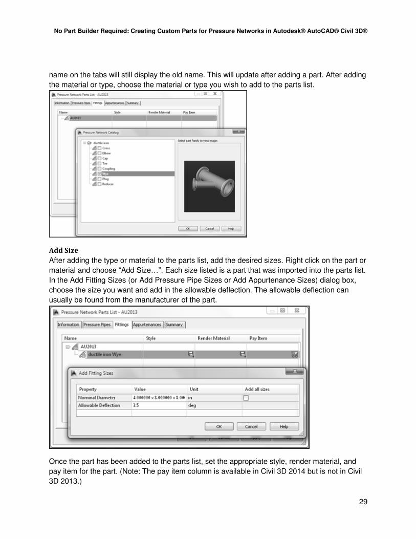
name on the tabs will still display the old name. This will update after adding a part. After adding
the material or type, choose the material or type you wish to add to the parts list.
Add Size
After adding the type or material to the parts list, add the desired sizes. Right click on the part or
material and choose “Add Size…”. Each size listed is a part that was imported into the parts list.
In the Add Fitting Sizes (or Add Pressure Pipe Sizes or Add Appurtenance Sizes) dialog box,
choose the size you want and add in the allowable deflection. The allowable deflection can
usually be found from the manufacturer of the part.
Once the part has been added to the parts list, set the appropriate style, render material, and
pay item for the part. (Note: The pay item column is available in Civil 3D 2014 but is not in Civil
3D 2013.)

No Part Builder Required: Creating Custom Parts for Pressure Networks in Autodesk® AutoCAD® Civil 3D®
30
Exercise
1. Create the File and Set the Catalog
• In Civil 3D, close any files you may have open.
• On the Application Menu (the big blue “A” in the top left of the application window),
select New (or press ctrl+N)
• Use the default imperial template, “_AutoCAD Civil 3D (Imperial) NCS.dwt” for the new
drawing.
2. Set the Pressure Network Catalog
• On the Home tab of the Ribbon, expand out the Create Design panel and choose, “Set
Pressure Network Catalog.
• In the Set Pressure Network Catalog dialog box, click the ellipsis (the button with the
three periods…) for the “Catalog folder…” and browse to the following folder:
"C:\Datasets\Wednesday\CI1472-L No Part Builder Required - Creating Custom Parts

No Part Builder Required: Creating Custom Parts for Pressure Networks in Autodesk® AutoCAD® Civil 3D®
31
for Pressure Networks in Civil 3D\Catalog". Under the “Catalog database file:” choose
the catalog – “AU2013 No Part Builder Required.sqlite” and press OK.
3. Create the Parts List
• On the Settings tab of the Toolspace in Civil 3D expand out Pressure Network. Right
click on Parts List and select “New…”.
No Part Builder Required: Creating Custom Parts for Pressure Networks in Autodesk® AutoCAD® Civil 3D®
32
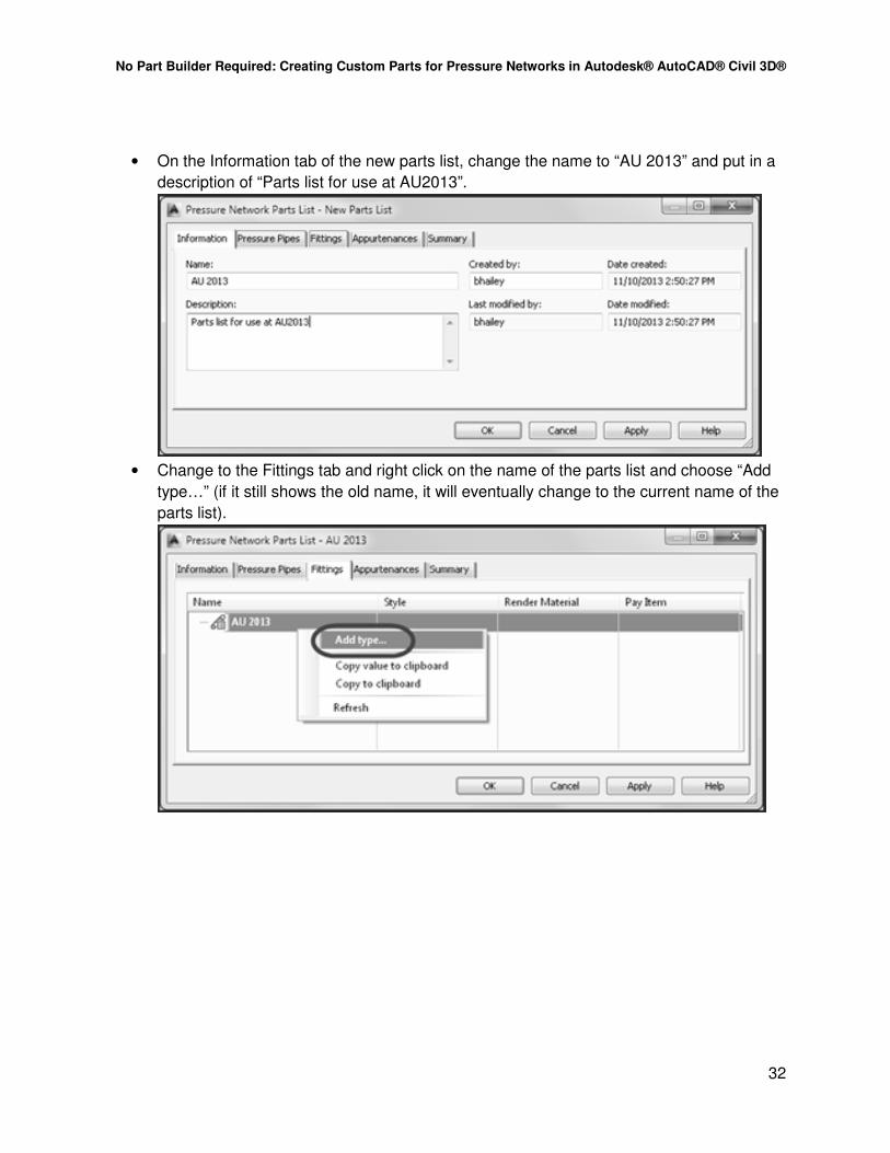
• On the Information tab of the new parts list, change the name to “AU 2013” and put in a
description of “Parts list for use at AU2013”.
• Change to the Fittings tab and right click on the name of the parts list and choose “Add
type…” (if it still shows the old name, it will eventually change to the current name of the
parts list).

No Part Builder Required: Creating Custom Parts for Pressure Networks in Autodesk® AutoCAD® Civil 3D®
33
• In the Pressure Network Catalog dialog box, toggle on Wye and click OK.
• Back on the Fittings tab of the Pressure Network Parts List – AU 2013, expand out the
parts list name “AU 2013”, right click on “ductile iron Wye”, and select “Add size…”.
No Part Builder Required: Creating Custom Parts for Pressure Networks in Autodesk® AutoCAD® Civil 3D®
34
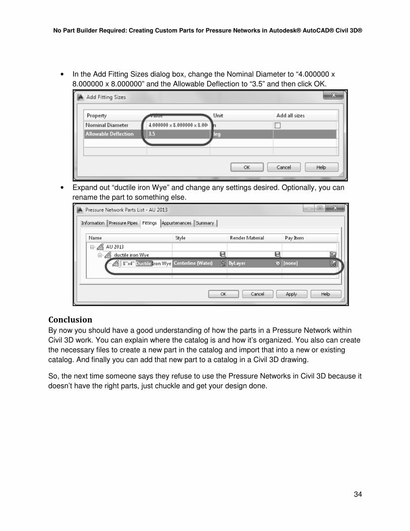
• In the Add Fitting Sizes dialog box, change the Nominal Diameter to “4.000000 x
8.000000 x 8.000000” and the Allowable Deflection to “3.5” and then click OK.
• Expand out “ductile iron Wye” and change any settings desired. Optionally, you can
rename the part to something else.
Conclusion
By now you should have a good understanding of how the parts in a Pressure Network within
Civil 3D work. You can explain where the catalog is and how it’s organized. You also can create
the necessary files to create a new part in the catalog and import that into a new or existing
catalog. And finally you can add that new part to a catalog in a Civil 3D drawing.
So, the next time someone says they refuse to use the Pressure Networks in Civil 3D because it
doesn’t have the right parts, just chuckle and get your design done.