noise - california energy commission 5.7: noise 5.7-2 is061411043744sac/420246/112110005 . tecopa/sr...
TRANSCRIPT

SECTION 5.7: NOISE
IS061411043744SAC/420246/112110005 5.7-1
5.7 Noise 5.7.1 Introduction The Hidden Hills Solar Electric Generating System (HHSEGS) will be located on privately owned land in Inyo County, California, adjacent to the Nevada border. It will comprise two solar fields and associated facilities: the northern solar plant (Solar Plant 1) and the southern solar plant (Solar Plant 2). Each solar plant will generate 270 megawatts (MW) gross (250 MW net), for a total net output of 500 MW. Solar Plant 1 will occupy approximately 1,483 acres (or 2.3 square miles), and Solar Plant 2 will occupy approximately 1,510 acres (or 2.4 square miles). A 103-acre common area will be established on the southeastern corner of the site to accommodate an administration, warehouse, and maintenance complex, and an onsite switchyard. A temporary construction laydown and parking area on the west side of the site will occupy approximately 180 acres.
Each solar plant will use heliostats—elevated mirrors guided by a tracking system mounted on a pylon—to focus the sun’s rays on a solar receiver steam generator (SRSG) atop a tower near the center of each solar field. The solar power tower technology for the HHSEGS project design incorporates an important technology advancement, the 750-foot-tall solar power tower. One principle advantage of the HHSEGS solar power tower design is that it results in more efficient land use and greater power generation. The new, higher, 750-foot solar power tower allows the heliostat rows to be placed closer together, with the mirrors at a steeper angle. This substantially reduces mirror shading and allows more heliostats to be placed per acre. More megawatts can be generated per acre and the design is more efficient overall.
In each solar plant, one Rankine-cycle steam turbine will receive steam from the SRSG (or solar boiler) to generate electricity. The solar field and power generation equipment will start each morning after sunrise and, unless augmented, will shut down when insolation drops below the level required to keep the turbine online. Each solar plant will include a natural-gas-fired auxiliary boiler, used to augment the solar operation when solar energy diminishes or during transient cloudy conditions, as well as a startup boiler, used during the morning startup cycle, and a nighttime preservation boiler, used to maintain system temperatures overnight. On an annual basis heat input from natural gas will be limited by fuel use and other conditions to less than 10 percent of the heat input from the sun.
To save water in the site’s desert environment, each solar plant will use a dry-cooling condenser. Cooling will be provided by air-cooled condensers, supplemented by a partial dry-cooling system for auxiliary equipment cooling. Raw water will be drawn daily from onsite wells located in each power block and at the administration complex. Groundwater will be treated in an onsite treatment system for use as boiler make-up water and to wash the heliostats.
Two distinct transmission options are being considered because of a unique situation concerning Valley Electric Association (VEA). Under the first option, the project would interconnect via a 230-kilovolt (kV) transmission line to a new VEA-owned substation (Tap Substation) at the intersection of Tecopa Road1
1 The road is also called Tecopa Highway and Old Spanish Trail Highway. The names are generally used interchangeably.
and Nevada State Route (SR) 160 (the

SECTION 5.7: NOISE
5.7-2 IS061411043744SAC/420246/112110005
Tecopa/SR 160 Option). The other option is a 500-kV transmission line that interconnects to the electric grid at the Eldorado Substation (the Eldorado Option), in Boulder City, Nevada.
A 12- to 16-inch-diameter natural gas pipeline will be required for the project. It will exit the HHSEGS site at the California-Nevada border and travel on the Nevada side southeast along the state line, then northeast along Tecopa Road until it crosses under SR 160. From this location a 36-inch line will turn southeast and continue approximately 26 miles, following the proposed Eldorado Option transmission line corridor, to intersect with the Kern River Gas Transmission (KRGT) pipeline. A tap station will be constructed at that point to connect it to the KRGT line. The total length of the natural gas pipeline will be approximately 35.3 miles.
The transmission and natural gas pipeline alignments will be located in Nevada, primarily on federal land managed by the U.S. Bureau of Land Management (BLM), except for small segments of the transmission line (both options) in the vicinity of the Eldorado Substation, which is located within the city limits of Boulder City, Nevada. A detailed environmental impact analysis of the transmission and natural gas pipeline alignments will be prepared by BLM.
This section is organized as follows: Section 5.7.2 describes the noise laws, ordinances, regulations, and standards (LORS) that may apply to the project. A summary of the fundamentals of acoustics that provide a baseline for noise study is provided in Section 5.7.3. A discussion of existing noise levels in the project area (affected environment) is included in Section 5.7.4. The environmental analysis to determine potential impacts and potential cumulative impacts to noise due to construction and operation of the project are provided in Sections 5.7.5 and 5.7.6, respectively. Mitigation measures proposed for the project are provided in Section 5.7.7. Agencies and agency contacts are included in Section 5.7.8 and applicable permits and permit schedules are listed in Section 5.7.9. The references cited in the preparation of this section are listed in Section 5.7.10
5.7.2 Laws, Ordinances, Regulations, and Standards The following LORS will apply to noise generated by the project. They are summarized in Table 5.7-1.
5.7.2.1 Federal LORS 5.7.2.1.1 U.S. Environmental Protection Agency Guidelines, which are advisory and not mandatory, are available from the U.S. Environmental Protection Agency (EPA, 1974) to assist state and local government entities in development of state and local LORS for noise.
5.7.2.1.2 Occupational Safety and Health Act Onsite noise levels are regulated, in a sense, through the Occupational Safety and Health Act of 1970 (OSHA). The noise exposure level of workers is regulated at 90 decibels, A-weighted (dBA), over an 8-hour work shift to protect hearing (29 Code of Federal Regulations 1910.95). Onsite noise levels will generally be in the 70- to 85-dBA range. Areas above 85 dBA will be posted as high noise level areas and hearing protection will be required. HHSEGS will implement a hearing conservation program for applicable employees and maintain 8-hour exposure levels below 90 dBA.

SECTION 5.7: NOISE
IS061411043744SAC/420246/112110005 5.7-3
TABLE 5.7-1 Laws, Ordinances, Regulations, and Standards Applicable to Noise
LORS Requirements/ Applicability Administering Agency
AFC Section Explaining
Conformance
Federal
EPA Guidelines for state and local governments.
EPA Section 5.7.2.1.1.
OSHA Exposure of workers over 8-hour shift limited to 90 dBA.
OSHA Sections 5.7.2.1.2, 5.7.5.2.1, and 5.7.5.3.1. Also see Section 5.16, Worker Safety
State
Cal-OSHA 8 CCR Article 105 Sections 095 et seq.
Exposure of workers over 8-hour shift limited to 90 dBA.
Cal-OSHA Sections 5.7.2.2.1, 5.7.5.2.1, and 5.7.5.3.1. Also see Section 5.16, Worker Safety
Calif. Vehicle Code Sections 23130 and 23130.5
Regulates vehicle noise limits on California highways.
Caltrans, California Highway Patrol and the County Sheriff’s Office
Delivery trucks and other vehicles will meet Code requirements.
Local
California Government Code Section 65302
Requires local government to prepare plans that contain noise provisions.
Inyo County Section 5.7.2.3.
Inyo County General Plan
The County General Plan establishes acceptable levels for noise based on land use.
Inyo County Sections 5.7.2.3 and 5.7.5.3.4.
Inyo County Code The County Code does not establish specific numeric limits that are applicable to the operation of the project. Rather it requires the County Planning Commission to establish an appropriate noise limit.
Inyo County Sections 5.7.2.3 and 5.7.5.3.4.
5.7.2.2 State LORS 5.7.2.2.1 California Occupational Safety and Health Administration The California Department of Industrial Relations, Division of Occupational Safety and Health enforces California Occupational Safety and Health Administration (Cal-OSHA) regulations, which are the same as the federal OSHA regulations described previously. The regulations are contained in Title 8 of the California Code of Regulations (CCR), General Industrial Safety Orders, Article 105, Control of Noise Exposure, Sections 5095, et seq.

SECTION 5.7: NOISE
5.7-4 IS061411043744SAC/420246/112110005
5.7.2.2.2 California Vehicle Code Noise limits for highway vehicles are regulated under the California Vehicle Code, Sections 23130 and 23130.5. The limits are enforceable on the highways by the California Highway Patrol and the County Sheriff’s Office.
5.7.2.3 Local LORS The California State Planning Law (California Government Code Section 65302) requires that all cities, counties, and entities (such as multi-city port authorities) prepare and adopt a General Plan to guide community change. Because the project is located within unincorporated Inyo County, the County would have jurisdiction over the project with regards to noise regulations if not for the Commission’s exclusive jurisdiction over thermal power plants 50 MWs or greater.
5.7.2.3.1 Inyo County The Inyo County 2001 General Plan Public Safety Element addresses noise and establishes goals, policies and implementation measures that regulate noise occurring within the County’s jurisdiction. Table 5.7-2 summarizes the noise levels used by the County for evaluating land use compatibility. For residences, schools and churches, the Noise Element established a Normally Acceptable Day-Night Noise Level (Ldn) of 60 dBA and a Conditionally Acceptable Ldn of 70 dBA. The Normally Acceptable Ldn of 60 dBA equates to an Equivalent Noise Level (Leq) of 60 dBA during the day and 50 dBA during the night or 54 dBA continuously throughout the day and night. The Conditionally Acceptable Ldn of 70 dBA equates to an Leq of 70 dBA during the day and 60 dBA during the night or 64 dBA continuously throughout the day and night.
In the event that acceptable outdoor noise levels cannot be achieved by appropriate mitigation measures, the General Plan notes that indoor noise levels for residential uses shall be designed to not exceed 45 dBA Ldn.
The General Plan also requires that construction activities occurring within 500 feet of existing noise sensitive uses be limited to the hours of 7:00 a.m. to 7:00 p.m. Monday through Saturday. Construction activities on Sunday or federal holidays for projects subject to Inyo County’s jurisdiction require a special permit from the County.
While the County has not established a separate noise ordinance, Title 21, Chapter 21.20.20, (Development Standards for Renewable Energy Development) of the Inyo County Code states that the County Board of Supervisors shall incorporate into development agreements and the planning commission shall impose noise standards that are deemed appropriate.

SECTION 5.7: NOISE
IS061411043744SAC/420246/112110005 5.7-5
TABLE 5.7-2 Maximum Allowable Ambient Noise Exposure by Land Use (Inyo County Noise Standards)
Land Use Type Noise Level (Ldn)
0-55 56-60 61-65 66-70 71-75 75-80 >81 Residential
Hotels, Motels
Schools, Libraries, Churches, Hospitals, Extended Care Facilities
Auditoriums, Concert Halls, Amphitheaters
Sports Arenas, Outdoor Spectator Sports
Playgrounds, Neighborhood Parks
Golf Courses, Riding Stables, Water Recreation, Cemeteries
Office Buildings, Business Commercial and Professional
Mining, Industrial, Manufacturing, Utilities, Agriculture
Normally Acceptable. Specified land use is satisfactory, based on the assumption that any buildings involved are of normal, conventional construction, without any special noise insulation requirements.
Conditionally Acceptable. New construction or development should be undertaken only after a detailed analysis of the noise reduction requirements is made and needed insulation features have been included in the design.
Unacceptable. New construction or development should not be undertaken.
If existing noise standards are currently exceeded, a proposed project shall not incrementally increase noise levels by more than 3 dBA.
Source: Inyo County General Plan. Website: http://www.inyoplanning.org/general_plan/index.htm. Accessed March 25, 2011.
5.7.3 Fundamentals of Acoustics Acoustics is the study of sound, and noise is defined as unwanted sound. Airborne sound is a rapid fluctuation or oscillation of air pressure above and below atmospheric pressure creating a sound wave. Acoustical terms used in this subsection are summarized in Table 5.7-3.

SECTION 5.7: NOISE
5.7-6 IS061411043744SAC/420246/112110005
TABLE 5.7-3 Definitions of Acoustical Terms
Term Definition
Ambient Noise Level The composite of noise from all sources near and far. The normal or existing level of environmental noise or sound at a given location. The ambient level is typically defined by the Leq level.
Background Noise Level The underlying ever-present lower level noise that remains in the absence of intrusive or intermittent sounds. Distant sources, such as traffic, typically makeup the background. The background level is generally defined by the L90 percentile noise level.
Intrusive Noise that intrudes over and above the existing ambient noise at a given location. The relative intrusiveness of a sound depends upon its amplitude, duration, frequency, time of occurrence, tonal content, the prevailing ambient noise level as well as the sensitivity of the receiver. The intrusive level is generally defined by the L10 percentile noise level.
Decibel (dB) A unit describing the amplitude of sound, equal to 20 times the logarithm to the base 10 of the ratio of the pressure of the sound measured to the reference pressure, which is 20 micropascals (20 micronewtons per square meter).
A-Weighted Sound Level (dBA) The sound level in decibels as measured on a sound level meter using the A-weighted filter network. The A-weighted filter de-emphasizes the very low and very high frequency components of the sound in a manner similar to the frequency response of the human ear and correlates well with subjective reactions to noise. All sound levels in this report are A-weighted.
Equivalent Noise Level (Leq) The average A-weighted noise level, on an equal energy basis, during the measurement period.
Percentile Noise Level (Ln) The noise level exceeded during n percent of the measurement period, where n is a number between 0 and 100 (e.g., L90)
Day-Night Noise Level (Ldn or DNL)
The average A-weighted noise level during a 24-hour day, obtained after addition of 10 decibels from 10:00 p.m. to 7:00 a.m.
The most common metric is the overall A-weighted sound level measurement that has been adopted by regulatory bodies worldwide. The A-weighting network measures sound in a similar fashion to how a person perceives or hears sound, thus achieving very good correlation in terms of how to evaluate acceptable and unacceptable sound levels.
A-weighted sound levels are typically measured or presented as equivalent sound pressure level (Leq), which is defined as the average noise level, on an equal energy basis for a stated period of time and is commonly used to measure steady state sound or noise that is usually dominant. Statistical methods are used to capture the dynamics of a changing acoustical environment. Statistical measurements are typically denoted by Lxx, where xx represents the percentile of time the sound level is exceeded. The L90 is a measurement that represents the noise level that is exceeded during 90 percent of the measurement period. Similarly, the L10 represents the noise level exceeded for 10 percent of the measurement period.

SECTION 5.7: NOISE
IS061411043744SAC/420246/112110005 5.7-7
Some metrics used in determining the impact of environmental noise consider the differences in response that people have to daytime and nighttime noise levels. During the nighttime, exterior background noises are generally lower than the daytime levels. However, most household noise also decreases at night and exterior noise becomes more noticeable. Furthermore, most people sleep at night and are sensitive to intrusive noises. To account for human sensitivity to nighttime noise levels, the Day-Night Sound Level (Ldn or DNL) was developed. Ldn is a noise index that accounts for the greater annoyance of noise during the nighttime hours.
Ldn values are calculated by averaging hourly Leq sound levels for a 24-hour period, and apply a weighting factor to nighttime Leq values. The weighting factor, which reflects the increased sensitivity to noise during nighttime hours, is added to each hourly Leq sound level before the 24-hour Ldn is calculated. For the purposes of assessing noise, the 24-hour day is divided into two time periods, with the following weightings:
• Daytime: 7 a.m. to 10 p.m. (15 hours) Weighting factor of 0 decibels (dB) • Nighttime: 10 p.m. to 7 a.m. (9 hours) Weighting factor of 10 dB
The two time periods are then averaged to compute the overall Ldn value. For a continuous noise source, the Ldn value is easily computed by adding 6.4 dB to the overall 24-hour noise level (Leq). For example, if the expected continuous noise level from the power plant were 60.0 dBA, the resulting Ldn from the plant would be 66.4 dBA.
The effects of noise on people can be listed in three general categories:
• Subjective effects of annoyance, nuisance, dissatisfaction • Interference with activities such as speech, sleep, learning • Physiological effects such as startling and hearing loss
In most cases, environmental noise may produce effects in the first two categories only. However, workers in industrial plants may experience noise effects in the last category. No completely satisfactory way exists to measure the subjective effects of noise, or to measure the corresponding reactions of annoyance and dissatisfaction. This lack of a common standard is primarily due to the wide variation in individual thresholds of annoyance and habituation to noise. Thus, an important way of determining a person’s subjective reaction to a new noise is by comparing it to the existing or “ambient” environment to which that person has adapted. In general, the more the level or the tonal (frequency) variations of a noise exceed the previously existing ambient noise level or tonal quality, the less acceptable the new noise will be, as judged by the exposed individual.
Table 5.7-4 shows the relative A-weighted noise levels of common sounds measured in the environment and in industry for various sound levels.

SECTION 5.7: NOISE
5.7-8 IS061411043744SAC/420246/112110005
TABLE 5.7-4 Typical Sound Levels Measured in the Environment and Industry
Noise Source at a Given Distance
A-Weighted Sound Level in Decibels
Noise Environments
Subjective Impression
Shotgun (at shooter’s ear) 140 Carrier flight deck Painfully loud
Civil defense siren (100 feet) 130
Jet takeoff (200 feet) 120 Threshold of pain
Loud rock music 110 Rock music concert
Pile driver (50 feet) 100 Very loud
Ambulance siren (100 feet) 90 Boiler room
Pneumatic drill (50 feet) 80 Noisy restaurant
Busy traffic; hair dryer 70 Moderately loud
Normal conversation (5 feet) 60 Data processing center
Light traffic (100 feet); rainfall 50 Private business office
Bird calls (distant) 40 Average living room library Quiet
Soft whisper (5 feet); rustling leaves 30 Quiet bedroom
20 Recording studio
Normal breathing 10 Threshold of hearing
Source: Beranek, 1998.
5.7.4 Affected Environment The project site is located on privately owned land along the California-Nevada border, approximately 18 miles south of Pahrump, Nevada, and approximately 45 miles west of Las Vegas, Nevada. The area is sparsely populated, with a few scattered residences south and east of the HHSEGS site. The nearest residence to the HHSEGS property boundary is approximately 300 feet west of the fenceline (see Figure 5.9-1). The nearest residence to any power block equipment is approximately 3,500 feet south of the Solar Plant 2 power block and about 950 feet south of the project’s southern boundary.
The St. Therese Mission, a commercial facility, has broken ground on 17.5 acres approximately 0.5 mile from the HHSEGS boundary. It will consist of a chapel, columbarium, garden, restaurant, visitor’s center, playground, restrooms, and an onsite caretaker home.
The Front Sight Firearms Training Institute is located approximately 1.7 miles northeast of the project boundary in Nevada. The Front Sight Firearms Training Institute offers classes during both the day and nighttime hours, utilizing Uzi submachine guns, M16 rifles, and other weapons.
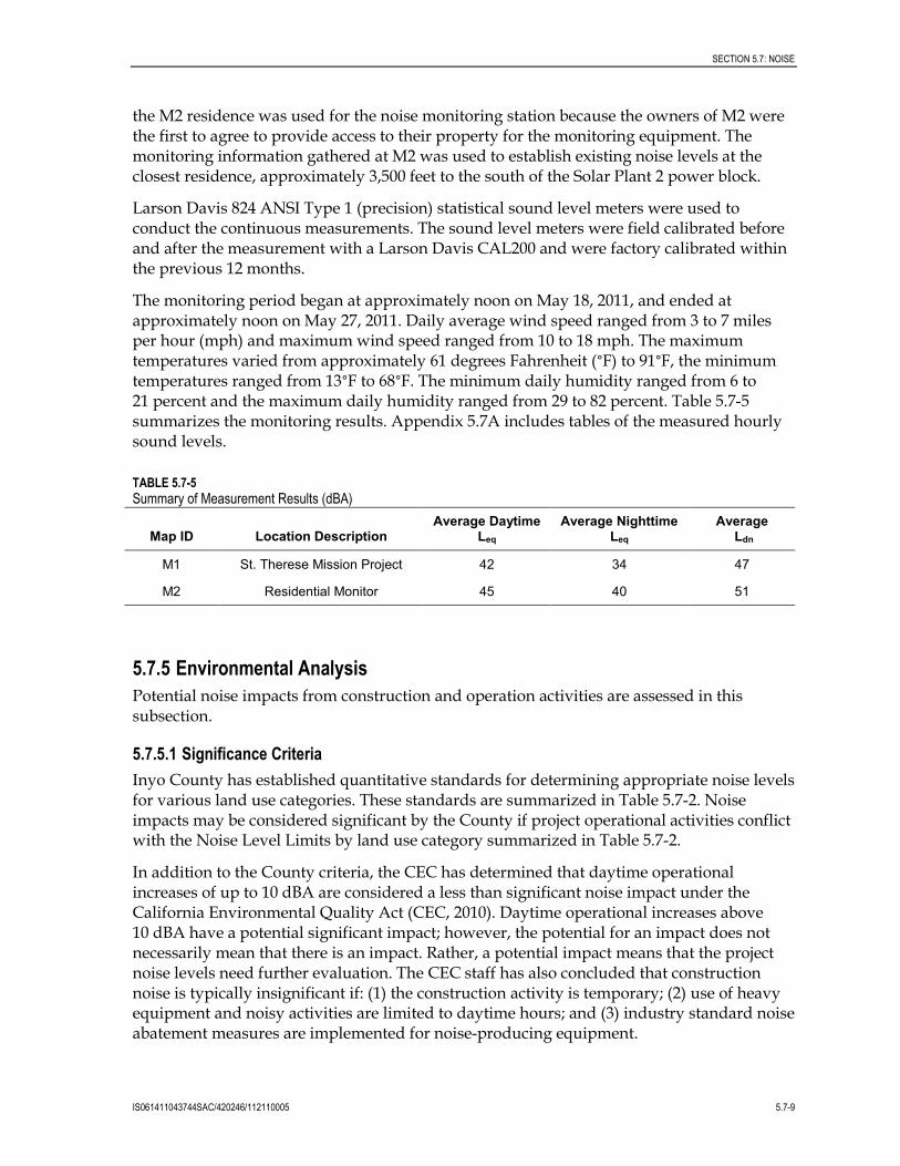
5.7.4.1 Ambient Noise Survey HHSEGS conducted continuous ambient noise monitoring at two monitoring locations (Figure 5.7-1) to determine the level of existing noise within the vicinity of the project. Specifically, HHSEGS monitored ambient noise from locations M1, the St. Therese Mission, and M2, a residence located south of the project. M2 is not the closest residence; however,
SECTION 5.7: NOISE
IS061411043744SAC/420246/112110005 5.7-9
the M2 residence was used for the noise monitoring station because the owners of M2 were the first to agree to provide access to their property for the monitoring equipment. The monitoring information gathered at M2 was used to establish existing noise levels at the closest residence, approximately 3,500 feet to the south of the Solar Plant 2 power block.
Larson Davis 824 ANSI Type 1 (precision) statistical sound level meters were used to conduct the continuous measurements. The sound level meters were field calibrated before and after the measurement with a Larson Davis CAL200 and were factory calibrated within the previous 12 months.
The monitoring period began at approximately noon on May 18, 2011, and ended at approximately noon on May 27, 2011. Daily average wind speed ranged from 3 to 7 miles per hour (mph) and maximum wind speed ranged from 10 to 18 mph. The maximum temperatures varied from approximately 61 degrees Fahrenheit (°F) to 91°F, the minimum temperatures ranged from 13°F to 68°F. The minimum daily humidity ranged from 6 to 21 percent and the maximum daily humidity ranged from 29 to 82 percent. Table 5.7-5 summarizes the monitoring results. Appendix 5.7A includes tables of the measured hourly sound levels.
TABLE 5.7-5 Summary of Measurement Results (dBA)
Map ID Location Description Average Daytime
Leq Average Nighttime
Leq Average
Ldn
M1 St. Therese Mission Project 42 34 47
M2 Residential Monitor 45 40 51
5.7.5 Environmental Analysis Potential noise impacts from construction and operation activities are assessed in this subsection.
5.7.5.1 Significance Criteria Inyo County has established quantitative standards for determining appropriate noise levels for various land use categories. These standards are summarized in Table 5.7-2. Noise impacts may be considered significant by the County if project operational activities conflict with the Noise Level Limits by land use category summarized in Table 5.7-2.
In addition to the County criteria, the CEC has determined that daytime operational increases of up to 10 dBA are considered a less than significant noise impact under the California Environmental Quality Act (CEC, 2010). Daytime operational increases above 10 dBA have a potential significant impact; however, the potential for an impact does not necessarily mean that there is an impact. Rather, a potential impact means that the project noise levels need further evaluation. The CEC staff has also concluded that construction noise is typically insignificant if: (1) the construction activity is temporary; (2) use of heavy equipment and noisy activities are limited to daytime hours; and (3) industry standard noise abatement measures are implemented for noise-producing equipment.
SECTION 5.7: NOISE
5.7-10 IS061411043744SAC/420246/112110005
5.7.5.2 Construction Impacts This subsection addresses the various components of construction noise and vibration.
5.7.5.2.1 Worker Exposure to Noise Worker exposure levels during construction of the HHSEGS will vary depending on the phase of the project and the proximity of the workers to the noise-generating activities. Hearing protection will be available for workers and visitors to use as needed throughout the duration of the construction period. A Hearing Protection Plan, which complies with Cal-OSHA requirements, will be incorporated into the project Health and Safety Plan.
5.7.5.2.2 Plant Construction Noise Construction of HHSEGS is expected to be similar to other power plants in terms of equipment used and other types of activities. The noise level will vary during the construction period, depending on the construction phase. Construction of power plants can generally be divided into five phases that use different types of construction equipment. The five phases are: (1) demolition, site preparation, and excavation; (2) concrete pouring; (3) steel erection; (4) mechanical; and (5) clean-up (Miller et al., 1978).
Both the EPA Office of Noise Abatement and Control and the Empire State Electric Energy Research Company have extensively studied noise from individual pieces of construction equipment as well as from construction sites of power plants and other types of facilities (EPA, 1971; Barnes et al., 1976). Because specific information on types, quantities, and operating schedules of construction equipment is not available at this point in project development, information from these documents for similarly sized industrial projects will be used. Use of this data, which is between 21 and 26 years old, is conservative because the evolution of construction equipment has been toward quieter designs to protect operators from exposure to high noise levels.
The loudest equipment types generally operating at a site during each phase of construction are presented in Table 5.7-6. The composite average or equivalent site noise level, representing noise from all equipment, is also presented in the table for each phase.
TABLE 5.7-6 Construction Equipment and Composite Site Noise Levels
Construction Phase
Loudest Construction Equipment
Equipment Noise Level (dBA) at
50 feet
Composite Site Noise Level
(dBA) at 50 feet
Composite Site Noise Level
(dBA) at 1 mile
Demolition, Site Clearing, and Excavation
Dump truck Backhoe
91 85 89 49
Concrete Pouring Truck Concrete mixer
91 85 78 38
Steel Erection Derrick crane Jack hammer
88 88 87 47
Mechanical Derrick crane Pneumatic tools
88 86 87 47
Cleanup Rock drill Truck
98 91 89 49
Source: EPA, 1971; Barnes et al., 1976.

SECTION 5.7: NOISE
IS061411043744SAC/420246/112110005 5.7-11
Table 5.7-7 presents noise levels from common construction equipment at various distances. These results are conservative because the only attenuating mechanism considered was divergence of the sound waves in open air. At a distance of 1 mile, atmospheric and other attenuation would result in at least another 7 dBA reduction.
TABLE 5.7-7 Noise Levels from Common Construction Equipment at Various Distances
Construction Equipment
Typical Sound Pressure Level (dBA)
50 feet 1,500 feet 3,000 feet 1 mile
Pile drivers (20,000-32,000 ft-lb/blow) 104 74 68 64
Dozer (250-700 hp) 88 58 52 48
Front end loader (6-15 cu. yds.) 88 58 52 48
Trucks (200-400 hp) 86 56 50 46
Grader (13 to 16 ft. blade) 85 55 49 45
Shovels (2-5 cu. yds.) 84 54 48 44
Portable generators (50-200 kW) 84 54 48 44
Derrick crane (11-20 tons) 83 53 47 43
Mobile crane (11-20 tons) 83 53 47 43
Concrete pumps (30-150 cu. yds.) 81 51 45 41
Tractor (3/4 to 2 cu. yds.) 80 50 44 40
Unquieted paving breaker 80 50 44 40
Quieted paving breaker 73 43 37 33
Note: At a distance of 1 mile, atmospheric and other attenuation would result in at least another 7 dBA reduction.
Noise generated during the testing and commissioning phase of the project is not expected to be substantially different from that produced during normal full-load operation. Starts and abrupt stops are more frequent during this period, but on the whole they are usually short-lived.
5.7.5.2.3 Construction Vibration Construction vibrations can be divided into three classes, based on the wave form and its source:
Wave form: Impact Example source: impact pile driver or blasting
Wave form: Steady state Example source: vibratory pile driver
Wave form: Pseudo steady state Example source: double acting pile hammer
Because a final geotechnical report has not been prepared, pile driving is currently anticipated and, if required, will be limited to daytime work hours.

SECTION 5.7: NOISE
5.7-12 IS061411043744SAC/420246/112110005
5.7.5.3 Operational Impacts 5.7.5.3.1 Worker Exposure to Operational Noise Nearly all components will be specified not to exceed near-field maximum noise levels of 90 dBA at 3 feet (or 85 dBA at 3 feet where available as a vendor standard). Because no permanent or semi-permanent workstations are located near any piece of noisy plant equipment, no worker’s time-weighted average exposure to noise should approach the level allowable under OSHA guidelines. Nevertheless, signs requiring the use of hearing protection devices will be posted in all areas where noise levels commonly exceed 85 dBA, such as inside acoustical enclosures. Outdoor levels throughout the plant will typically range from 90 dBA near certain equipment to roughly 65 dBA in areas more distant from any major noise source.
5.7.5.3.2 Plant Operation Noise Levels A noise model of the HHSEGS facility has been developed using source input levels derived from field measurements of similar equipment made at other existing plants, data supplied by manufacturers, or information found in the technical literature. The noise levels have been calculated at the closest residence and the St. Therese Mission site. The noise levels presented represent the anticipated steady-state level from the facility with all equipment operating, a condition that will occur only during daytime hours.
Standard acoustical engineering methods were used in the noise analysis. The noise model, CADNA/A by DataKustik GmbH of Munich, Germany is a very sophisticated noise model and enables full modeling of very complex industrial plants. The sound propagation factors used in the model have been adopted from ISO 9613-2 Acoustics—Sound Attenuation During Propagation Outdoors and VDI 2714 Outdoor Sound Propagation. The model divides the HHSEGS into a list of individual point and area noise sources representing each piece of equipment that produces a significant amount of noise. The sound power levels representing the standard performance of each of these components are assigned based either on field measurements of similar equipment made at other existing plants, data supplied by manufacturers, or information found in the technical literature. Using these standard power levels as a basis, the model calculates the sound pressure level that would occur at each receptor from each source after losses from distance, air absorption, blockages, and other factors are considered. The sum of all these individual levels is the total plant level at the modeling point.
The sound power levels, by octave band, used in the model are summarized in Table 5.7-8. As is typical at this stage of a project, this data is preliminary and detailed vendor specifications will ultimately be developed to ensure the project complies with the conditions of certification.

SECTION 5.7: NOISE
IS061411043744SAC/420246/112110005 5.7-13
TABLE 5.7-8 Sound Power Levels Used to Model HHSEGS, dBA
Plant Component Sound Power Level
dBA
Transformers 106
Steam Turbine Generator 111
Boiler Feed Water Pumps 109
Auxiliary Boiler 117
Air Cooled Condenser 112
Operational noise from the HHSEGS is predicted not to exceed 54 dBA at the closest residence or 52 dBA at the St. Therese Mission. Such levels comply with the County’s general plan requirements as discussed in Section 5.7.2.3.1.
5.7.5.3.3 Nighttime Noise Given the solar nature of this project, activity at night will be limited to primarily maintenance related activities such as mirror washing. Mirror washing activities are expected to be similar in sound level to a heavy truck. Mirror washing will move around the project area returning to a particular group of mirrors approximately every 2 weeks.
5.7.5.3.4 Tonal Noise While certain sources within a power plant such as transformers, pump motors, and fan gearboxes have been known to sometimes produce significant tones, at the receptor locations modeled for HHSEGS, no significant tones are anticipated. It is the Applicant’s intention to anticipate the potential for audible tones in the design and specification of the plant’s equipment and take necessary steps to prevent sources from emitting tones that might be disturbing at the nearest receptors.
5.7.5.3.5 Ground and Airborne Vibration An unexpected and unanticipated imbalance in the power plant equipment could contribute to ground vibration levels in the vicinity of the equipment. The equipment is, however, well balanced and designed to produce very low vibration levels throughout the life of the project. Furthermore, vibration-monitoring systems installed in the equipment are designed to ensure that the equipment remains balanced. If an imbalance occurs, the event would be detected and the equipment would automatically shut down.
5.7.5.3.6 Transmission Line and Switchyard Noise Levels One of the electrical effects of high-voltage transmission lines is corona. Corona is the ionization of the air that occurs at the surface of the energized conductor and suspension hardware due to very high electric field strength at the surface of the metal during certain conditions. Corona may result in radio and television reception interference, audible noise, light, and production of ozone. Corona is generally a principle concern with transmission lines of 345 kV and higher. Given the lack of receptors and that power will only be transmitted during daytime hours when ambient noise levels are typically highest and humidity lowest, corona noise is not anticipated to be significant.
SECTION 5.7: NOISE
5.7-14 IS061411043744SAC/420246/112110005
5.7.6 Cumulative Effects A cumulative effect refers to a proposed project’s incremental effect together with other closely related past, present, and reasonably foreseeable future projects whose impacts may compound or increase the incremental effect of the proposed project (Public Resources Code § 21083; 14 CCR §§ 15064(h), 15065(c), 15130, and 15355). Cumulative projects are described in Section 5.6.7 and include the Pahrump Valley General Aviation Airport, St. Therese Mission (a commercial enterprise), and the Element Power Solar Project. Standard engineering practices are expected to reduce the potential for impacts due to noise that could result from implementation of these projects in conjunction with HHSEGS.
The St. Therese Mission is the only proposed project near the HHSEGS site to potentially result in a cumulative noise effect. The facility developer estimates that as many as 1,200 visitors per month could visit the facility. The noise generated from such visitors would be predominately associated with vehicular travel. Other features associated with the St. Therese Mission project are not anticipated to be significant sources of noise. Therefore, it is unlikely that HHSEGS would have impacts that would combine with other closely related past, present, and reasonably foreseeable future projects to create a significant cumulative impact.
5.7.7 Mitigation Measures HHSEGS anticipates implementing the following mitigation measures.
5.7.7.1 Noise Mitigation Measure #1 The project owner will establish a telephone number for use by the public to report any significant undesirable noise conditions associated with the construction and operation of the project. If the telephone is not staffed 24 hours per day, the project owner will include an automatic answering feature, with date and time stamp recording, to answer calls when the phone is unattended. This telephone number will be posted at the project site during construction in a manner visible to passersby. This telephone number will be maintained until the project has been operational for at least 1 year.
5.7.7.2 Noise Mitigation Measure #2 Throughout the construction and operation of the project, the project owner will document, investigate, evaluate, and attempt to resolve all legitimate project-related noise complaints.
The project owner or authorized agent will:
• Use the Noise Complaint Resolution Form typically suggested by CEC or functionally equivalent procedure to document and respond to each noise complaint
• Attempt to contact the person(s) making the noise complaint within 24 hours
• Conduct an investigation to attempt to determine the source of noise related to the complaint
• If the noise complaint is legitimate, take all feasible measures to reduce the noise at its source
SECTION 5.7: NOISE
IS061411043744SAC/420246/112110005 5.7-15
5.7.7.3 Noise Mitigation Measure #3 Noisy construction activities occurring within 500 feet of a noise sensitive use will be restricted to 7:00 a.m. to 7:00 p.m., Monday through Saturday.
Project-related haul trucks will be operated in accordance with posted speed limits, and truck engine exhaust brake use will be limited to emergencies.
5.7.8 Involved Agencies and Agency Contacts TABLE 5.7-9 Agency Contacts for Noise
Issue Agency Contact
County Development Code and General Plan Requirements
Inyo County Planning Department Tanda Gretz Senior Planner Ph: (760) 878-0263 Fax: (760) 878-0382 Email: [email protected]
5.7.9 Permits Required and Permit Schedule No permits are required for noise; therefore, there is no permit schedule.
5.7.10 References Barnes, J.D., L.N. Miller, and E.W. Wood. 1976. Prediction of noise from power plant construction. Bolt Beranek and Newman, Inc. Cambridge, MA. Prepared for the Empire State Electric Energy Research Corporation, Schenectady, NY.
Beranek, L.L. 1998. Noise and Vibration Control. Institute of Noise Control Engineering. McGraw Hill.
California Energy Commission. 2010. Calico Solar Power Project Commission Decision, CEC-800-2010-012-CMF. Sacramento, California.
County of Inyo. 2001. General Plan. http://www.inyoplanning.org/general_plan/index.htm.
County of Inyo. 2010. Zoning Ordinance Title 21. June 2, 2011. http://www inyoplanning.org/documents/RenewableEnergyOrdinance-Final.pdf
International Organization for Standardization. 1996. Acoustics—Attenuation of Sound During Propagation Outdoors, Part 2: General Method of Calculation.ISO 9613-2, Geneva, Switzerland. Miller, Laymon N., et al.1984.Electric Power Plant Environmental Noise Guide, 2nd Edition, Edison Electric Institute, New York.
Miller, L.N., E.W. Wood, R.M. Hoover, A.R. Thompson, and S.L. Thompson, and S. L. Paterson. 1978. Electric Power Plant Environmental Noise Guide, Vol. 1. Bolt, Beranek& Newman, Inc. Cambridge, MA. Prepared for the Edison Electric Institute, New York, NY.

SECTION 5.7: NOISE
5.7-16 IS061411043744SAC/420246/112110005
U.S. Environmental Protection Agency (EPA). 1971. Noise from Construction Equipment and Operations, US Building Equipment, and Home Appliances. Prepared by Bolt, Beranek& Newman, Inc. for EPA Office of Noise Abatement and Control, Washington, DC.
U.S. Environmental Protection Agency (EPA). 1974. Information on Levels of Environmental Noise Requisite to Protect Public Health and Welfare with an Adequate Margin of Safety, EPA-550/9-74-004, EPA. U.S. Environmental Protection Agency (March 1974).
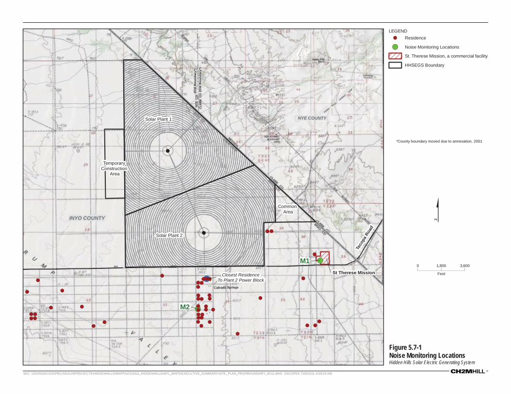
Figure 5.7-1Noise Monitoring LocationsHidden Hills Solar Electric Generating System
*County boundary moved due to annexation, 2001
!(
!(
!(
!(
!
!(
!(
!(
!(!(!(!(
!(
!(
!(!(
!(!(!(!(!(!(
!(
!(!(!( !(
!(!(
!(
!( !(!( !(
!(!(!(!(!(!(
!(
!(
!( !(!(
!(
!(
!(!(
INYO COUNTY
Teco
pa R
oad
Closest ResidenceTo Plant 2 Power Block
(Old
Bou
ndar
y*)
(Old
Bou
ndar
y*)
NYE COUNTY
Solar Plant 2
Solar Plant 1
Common Area
Temporary Construction
Area
M2
M1St Therese Mission
0 3,6001,800
Feet
LEGEND!( Residence
!( Noise Monitoring Locations
St. Therese Mission, a commercial facility
HHSEGS Boundary
$
SAC \\ZION\SACGIS\PROJ\SOLARPROJECTS\HIDDENHILLS\MAPFILES\2011_HIDDENHILLS\AFC_MAPS\EXECUTIVE_SUMMARY\SITE_PLAN_PROPBOUNDARY_8X11.MXD SSCOPES 7/28/2011 9:09:03 AM