noise reduction and heat-dissipating of … · noise reduction and heat-dissipating of...
TRANSCRIPT

1
NOISE REDUCTION AND HEAT-DISSIPATING OF REFRIG-ERATORS BY USING PERFORATED ACOUSTIC MET-AMATERIALS
Wei Wang, Xiaole Wang and Zhenyu Huang
Shanghai Jiao Tong University, School of Electronic Information and Electrical Engineering, Shanghai,
200240, People’s Republic of China
email: [email protected]
Qiang Fan
Haier Advanced Innovation Centre, Qingdao, Shandong, 266101, People’s Republic of China
A novel perforated-membrane-type acoustic metamaterial (PAM) was developed recently which
possesses orifices in each unit cell. The PAM was found of high sound insulation levels due to
the counterbalancing effects of sound waves in the far-field at certain frequencies. Meanwhile,
the orifices allow the airflow pass through freely and hence can well maintain the heat transmis-
sion between the two sides of PAM. In the present paper, a PAM-panel sample was designed and
fabricated, whose high-sound-insulation performance frequency range was particularly selected
to match with the high-sound-level frequencies of a refrigerator compressor. The sound transmis-
sion loss (STL) of the PAM panel was first simulated by FE modelling and then measured in the
sound impedance tube. Excellent agreements between the two sets of results were observed. Fi-
nally, an experimental application of the PAM-panel sample to the refrigerator was made for the
purpose of compressor noise control. An overall 5 dB reduction of the noise level was achieved
by replacing the original grid panel with the PAM panel.
Keywords: perforated-membrane-type acoustic metamaterial (PAM), finite element methods,
sound transmission loss, refrigerator compressor noise, noise control
1. Introduction
The main noise source of refrigerators is the compressor which usually emits noise at the low-
middle frequencies, e.g., 100 Hz up to 1000 Hz. The ideal noise control approach is to use thick and
heavy panels to enclose the compressor noise in an air-proof chamber [1]. However, this approach
cannot ensure the heat dissipating of the compressor effectively, and consequently normal operation
of the compressor may be affected. An alternative conventional way is to adopt perforated plates to
enclose the refrigerator by sacrificing some insulation effects of the low-middle frequency noise.
Therefore, it is very much desirable to have some special-formed panels which can be used to both
insulate the low-middle frequency noise and maintain the heat dissipation.
Previously in [2], G.C. Ma and P. Sheng et al. have demonstrated the noise insulation properties
of a panel structure made of membrane-type acoustic metamaterials (MAMs). The panel was formed
by four identical units of MAMs around a large orifice, through which the air can flow. The corre-
sponding sound transmission loss (STL) was found very large at the working frequencies with a nar-
row bandwidth, and hence the panel structure was considered as a bandstop filter with a narrow band-
width in low frequencies. The narrow frequency band, however, has largely limited the applications
of MAMs. Later in [3], S. J. Cho et al. proposed a two-dimensional heat-exhaust and soundproof
meta-structure, which was composed of periodic funnel-shaped units in a square lattice, and each unit
ICSV24, London, 23-27 July 2017
2 ICSV24, London, 23-27 July 2017
cell can operate as a Helmholtz resonator. In order to apply to the household appliances, the authors
in [4] also proposed honeycomb-shaped meta-structure for minimizing noise radiation and flowing
cooling air. Although the meta-structures can insulate the noise of narrow bandwidth, the structure is
too complex to manufacture. Recently in [5], we introduced a new, constrained-membrane-type
acoustic metamaterial (CAM) for low frequency sound insulation. The effective bandwidth of the
CAM tends to be the broadest at low frequencies compared with two other conventional MAMs with
the same static area density.
Inspired by the structure of the CAM, we further developed the perforated-membrane-type acous-
tic metamaterial (PAM) plate that possesses orifices in each unit cell. In the present paper, it has
shown that the PAM can achieve the good performances of both sound-insulation and heat-dissipation
while remain the advantages of simple structure and stable operation.
2. Brief Descriptions of PAM Structures
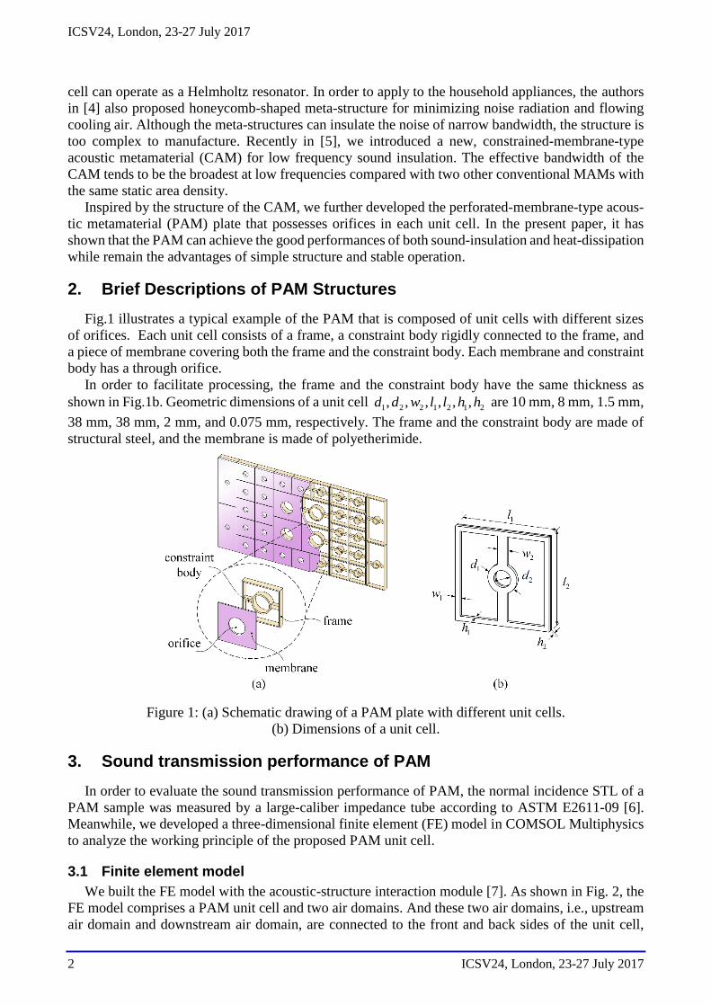
Fig.1 illustrates a typical example of the PAM that is composed of unit cells with different sizes
of orifices. Each unit cell consists of a frame, a constraint body rigidly connected to the frame, and
a piece of membrane covering both the frame and the constraint body. Each membrane and constraint
body has a through orifice.
In order to facilitate processing, the frame and the constraint body have the same thickness as
shown in Fig.1b. Geometric dimensions of a unit cell 1 2 2 1 2 1 2, , , , , ,d d w l l h h are 10 mm, 8 mm, 1.5 mm,
38 mm, 38 mm, 2 mm, and 0.075 mm, respectively. The frame and the constraint body are made of
structural steel, and the membrane is made of polyetherimide.
Figure 1: (a) Schematic drawing of a PAM plate with different unit cells.
(b) Dimensions of a unit cell.
3. Sound transmission performance of PAM
In order to evaluate the sound transmission performance of PAM, the normal incidence STL of a
PAM sample was measured by a large-caliber impedance tube according to ASTM E2611-09 [6].
Meanwhile, we developed a three-dimensional finite element (FE) model in COMSOL Multiphysics
to analyze the working principle of the proposed PAM unit cell.
3.1 Finite element model
We built the FE model with the acoustic-structure interaction module [7]. As shown in Fig. 2, the
FE model comprises a PAM unit cell and two air domains. And these two air domains, i.e., upstream
air domain and downstream air domain, are connected to the front and back sides of the unit cell,

ICSV24, London, 23-27 July 2017
ICSV24, London, 23-27 July 2017 3
respectively. In order to represent acoustic properties of an entire PAM plate, as well as to simplify
the computing complexity, the Floquet periodic boundary conditions are applied to the lateral faces
of the unit cell and the related air domains [8]. Both the air domains are terminated by perfectly
absorbing boundaries to avoid multi-reflections of sound waves. The FE model includes 293,751
elements and the element type employed for both the unit cell and the air domains is the tetrahedral.
The unit cell is excited by a harmonic plane wave with the amplitude of 1 Pa from the upstream air
domain.
The normal incidence STL can be calculated as:
10 I TSTL 20log P P= (1)
where PI and PT are amplitudes of the incident pressure and the transmitted pressure, respectively.
Figure 2: Schematic drawing of the FE model for simulating the normal incidence STL.
3.2 Experimental setup
Fig. 3a shows the photograph of the transmission tube, which mounts the PAM sample with rubber
rings for sealant. Two couples of 1/4 in. microphones (Type 4187, Bruel & Kjaer) in the incident and
transmission tube were separated by 100 mm to ensure the effective results with the frequency band
of 70-890 Hz.
Figure 3: (a) Experimental setup for measuring acoustic parameters using four-microphone.
(b) A normal view of the PAM sample.
3.3 Effective insulation properties
In order to analyze acoustic characteristics of the PAM, the sound transmission loss, the amplitude
of reflection and acoustic impedance of PAM were investigated both experimentally and numerically.
In the numerical simulations, the damping effects from the membrane material, the adhesive, and the
sealant are collectively represented by setting the loss factor of the membrane material of 0.05. In
ICSV24, London, 23-27 July 2017
4 ICSV24, London, 23-27 July 2017
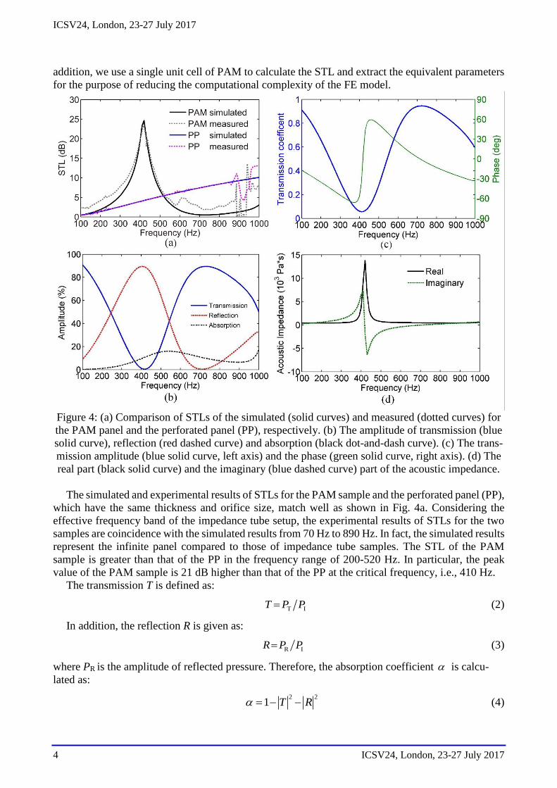
addition, we use a single unit cell of PAM to calculate the STL and extract the equivalent parameters
for the purpose of reducing the computational complexity of the FE model.
Figure 4: (a) Comparison of STLs of the simulated (solid curves) and measured (dotted curves) for
the PAM panel and the perforated panel (PP), respectively. (b) The amplitude of transmission (blue
solid curve), reflection (red dashed curve) and absorption (black dot-and-dash curve). (c) The trans-
mission amplitude (blue solid curve, left axis) and the phase (green solid curve, right axis). (d) The
real part (black solid curve) and the imaginary (blue dashed curve) part of the acoustic impedance.
The simulated and experimental results of STLs for the PAM sample and the perforated panel (PP),
which have the same thickness and orifice size, match well as shown in Fig. 4a. Considering the
effective frequency band of the impedance tube setup, the experimental results of STLs for the two
samples are coincidence with the simulated results from 70 Hz to 890 Hz. In fact, the simulated results
represent the infinite panel compared to those of impedance tube samples. The STL of the PAM
sample is greater than that of the PP in the frequency range of 200-520 Hz. In particular, the peak
value of the PAM sample is 21 dB higher than that of the PP at the critical frequency, i.e., 410 Hz.
The transmission T is defined as:
T IT P P (2)
In addition, the reflection R is given as:
R IR P P (3)
where PR is the amplitude of reflected pressure. Therefore, the absorption coefficient is calcu-
lated as:
2 21 T R (4)

ICSV24, London, 23-27 July 2017
ICSV24, London, 23-27 July 2017 5
The amplitudes of transmission, reflection and absorption are shown in Fig. 4b [9]. A transmission
dip and the corresponding reflection peak can be found at the critical frequency, which indicates that
most energy reflected by the unit cell of PAM. Fig. 4c shows the relationship between the amplitude
and phase of transmission. Moreover, at this frequency the phases switch from -90ºto 90ºdegrees.
Fig. 4d demonstrates the real part and the imaginary part of the acoustic impedance. The real parts of
the acoustic impedance are positive values in concerned band frequencies, i.e., 100-1000 Hz. The
imaginary part of the acoustic impedance becomes negative at the critical frequency due to the out-
of-phase motion of the unit cell with respect to the incident sound wave.
Figure 5: Velocity field distribution of the unit cell of PAM (a) and the PP (b) at the critical frequency.
(In the above figures, a plane wave is emitted from the left, represented by the large black arrows.
The white arrows show the direction of the air velocity. The rainbow color represents SPL of the
sample).
Fig. 5a presents the air velocity field nearby the unit cell of PAM when it works at the critical
frequency. We can see the out-of-phase motion between transmitted sound waves and incident waves
due to the vibration of the membrane. This motion results in high transmission loss at this frequency.
However, due to the in phase motion between transmitted sound waves and incident waves of the unit
cell of PP, the minimal SPL in the downstream domain is 86.9 dB which is 23.8 dB higher than that
of PAM. The SPL difference between PAM and the PP at the critical frequency is consistent with the
STL result illustrated in Fig. 4a.
4. Application of PAM to the refrigerator
The main noise source of the refrigerator is due to the compressor operation. In Fig. 6a, the com-
pressor is installed in a chamber at the bottom of the refrigerator. A grid panel was adopted to cover
the outlet face of the chamber to keep heat dissipating as shown in Fig. 6b. In order to insulate the
compressor noise, a PAM panel, which is fabricated based on the unit cell of PAM, is adopted to
substitute the grid panel. A microphone (BSWA, MA231) was positioned at the measurement point
where it is 20 cm from the central point of the panel, as shown in Fig.6a.

ICSV24, London, 23-27 July 2017
6 ICSV24, London, 23-27 July 2017
Figure 6: (a) Experimental setup for measuring sound radiation from a refrigerator.
(b) The original grid panel for the sound insulation of the compressor.
(c) The PAM panel for the sound insulation of the specific frequency.
(a) (b)
Figure 7: (a) Transient variation during on or off operation of the compressor.
(b) Comparisons of the SPL measured at the measurement point equipped with no panel (blue bar),
the original grid panel (red bar) and the PAM panel (black bar), respectively.
The SPL measured at the measurement point varies with respect to the time during on or off of the
compressor as shown in Fig. 7a. We chose the measured data from 1800 s to 3800 s for noise spectrum
analysis when the compressor operated end the steady-state condition. Fig. 7b shows the measured
SPLs at the measurement point of the refrigerator equipped with no panel, the original grid panel and
the PAM panel, respectively. The overall noise level was reduced by 5 dB by replacing the grid panel
with the PAM panel, especially 16 dB lower at the one-third octave frequency band of 400 Hz, which
includes the STL peak of the PAM panel.
In order to analyze the heat dissipation performance of the PAM panel, a thermal couple was
positioned at the surface of the compressor in the chamber. The temperature near the compressor
showed that only 2 ℃ increment could be found by replacing the original grid panel with the PAM
panel after 2 hours operation.
5. Conclusions
In the present paper, the sound-insulation and heat-dissipation advantages of PAM panels were
demonstrated numerically and experimentally. These were then further verified for actual application
to the refrigerator. The PAM is composed of unit cells with large size of orifices resulting in sound

ICSV24, London, 23-27 July 2017
ICSV24, London, 23-27 July 2017 7
energy dissipation at a specific frequency band, and meanwhile the orifices allow heat dissipation.
An FE model was developed to analyze the acoustic characteristics of PAM. The results of simula-
tions and experiments in the impedance tube show that PAM can greatly reflect sound energy at
special frequencies. The PAM panel was applied to the refrigerator for reduction of the compressor
noise. The overall noise level was reduced by 5 dB by replacing the original grid panel with the PAM
panel, especially 16 dB down at the noise peak frequency, with a small cost of 2 ℃ increment on the
compressor.
REFERENCES
1 Fahy, F. J., Sound and structural vibration: radiation, transmission and response. Academic press (2012).
2 Ma, G., Yang, M., Yang, Z., and Sheng, P. Low-frequency narrow-band acoustic filter with large orifice,
Applied Physics Letters, 103(1), 851-R, (2013).
3 Cho, S. J., Kim, B. S., Min, D. K., and Park, J. H. Tunable two-dimensional acoustic meta-structure com-
posed of funnel-shaped unit cells with multi-band negative acoustic property, Journal of Applied Physics,
118(16), 163103, (2015).
4 Cho, S. J., Kim, B. S., Min, D. K., Cho, Y. S., and Park, J. H. Honeycomb-shaped meta-structure for
minimizing noise radiation and resistance to cooling fluid flow of home appliances, Composite Structures,
155, 1-7, (2016).
5 Wang, X. L., Zhao, H., Luo, X. D., and Huang, Z. Y. Membrane-constrained acoustic metamaterials for
low frequency sound insulation, Applied Physics Letters, 108(4), 041905, (2016).
6 ASTM E2611-09: Standard Test Method for Measurement of Normal Incidence Sound Transmission of
Acoustical Materials Based on the Transfer Matrix Method (American Society for Testing and Materials,
New York), (2009).
7 Acoustic Module User's Guide of COMSOL Multiphysics 5.2a.
8 Wang, Y. F., Wang, Y. S., and Laude, V. Wave propagation in two-dimensional viscoelastic metamate-
rials, Physical Review B, 92(10), 104110, (2015).
9 Yang, M., Meng, C., Fu, C., Li, Y., Yang, Z., and Sheng, P. Subwavelength total acoustic absorption with
degenerate resonators, Applied Physics Letters, 107(10), 104104, (2015).