non binding operating and maintenance · operating and maintenance instructions progressive cavity...
TRANSCRIPT
Operating and Maintenance Instructions Progressive Cavity Pump Range
BT Non binding Operating and Maintenance Instructions seepex operating and maintenance instructions are individually compiled for each pump. These operating instructions are non binding and give only an overview. Binding operating instructions can be requested using the email address [email protected]. For this purpose, please also indicate the relevant pump comm. number.
This operating and maintenance instruction includes important safety information and instructions for installation, commissioning, operating and maintenance of the seepex machinery. It is essential therefore, that the responsible specialist refers to it before starting any work on the machinery as well as prior to commissioning. Futhermore, this instruction must always be available on site.

Operating and Maintenance Instructions Progressive Cavity Pump index item document denomination 1.0.0 OM.GEN.01e General 2.0.0 OM.SAF.01e Safety
OM.SAF.02e Safety 3.0.0 OM.TRA.01e Transport and Intermediate Storage 4.0.0 OM.DES.01e Description of the seepex pump and Accessories 5.0.0 OM.INS.01e Assembly and Installation 6.0.0 OM.COM.01e Commissioning/De-commissioning 7.0.0 Service and Maintenance
OM.MAI.04e BT 05-24 to 300-6L 7.1.0 Pin Joint Assembly
OM.PJT.04e BT 05-24 to 300-6L 7.2.0 OM.HBD.01e Holding Band Re-assembly 8.0.0 OM.REC.01e Breakdown, reasons, remedies 9.0.0 OM.ACC.01e Auxiliary seepex documentation
Sectional drawing and parts list 9.3.0 065-001B1 sectional drawing gland packing 9.4.0 SL.065.001 Part List 9.3.0 065-002B1 sectional drawing shaft sealing neutral 9.4.0 SL.065.002 Part List 9.5.0 Shaft Sealing
OM.SEA.Ae Gland packing Code A OM.SEA.01e Gland packing OM.SEA.02e Single acting Mechanical Seal 9.6.0 Wearing Parts and Gaskets
OM.WPS.04e BT 05-24 to 300-6L OM.SPT.01e Tools 10.0.0 OM.MDS.01e Manufacturer's documents from sub-supplier 99.0.0 OM.ADR.01e seepex Subsidiaries

Operating Instructions seepex Machine General
Dokument document Ausgabe issue Blatt sheet
OM.GEN.01e A / 10.12.94 1 (2)
1. General 1.1 Application These operating instructions contain basic infor-mation on the installation, commissioning and maintenance of seepex machines. Compliance with the work steps described in the individual sections is essential. 1.2 Details of the seepex machines 1.2.1 Operating Instructions The Commission Number (comm. no) assigns the operating instructions to a particular seepex machine. The operating instructions are produced in relation to a specific job/commission and are valid only for the machine whose comm. no. is identical with that indicated on the cover sheet and possessing the associated data sheet, Point 9. 1.2.2 Manufacturer The machines were manufactured by seepex. 1.2.3 Range, Size, Version of the machines are stated in the appended data sheet, Point 9. 1.2.4 Machine Comm. No. and Year of Construction are stated on the type plate at the machine. 1.2.5 Release Date of the Operating Instructions is stated on the cover sheet of the operating instructions. 1.2.6 Modifications, Notes of Modification If modifications to the machines are carried out in agreement with seepex, a new set of operating instructions will be provided, or the existing operating instructions will be supplemented by an additional sheet together with a new cover sheet. The date of modification and modification index will be noted on the new cover sheet.
1.2.7 EEC Machine Directive 1.2.7.1 Manufacturer's Declaration seepex Manufacturer's Declaration as required by the EEC Machine Directive 89/392/EEC, Appendix II B: The seepex machines delivered in accordance with our design are intended to be fitted in one machine or assembled together with other machines to form one machine/plant. The commissioning of the machine is forbidden until such a time as has been established that the entire machine/plant satisfies the requirements of the EEC Directive for Machines as amended 91/368/EEC and 93/44/EEC. Particular attention must be paid to the safety requirements specified in EN809 (s and Equipment for Fluids) as well as the information in these operating instructions. 1.2.7.2 Declaration of Conformity seepex machines possessing no safety accessories do not fulfill the requirements of the EEC Machine Directive 89/392/EEC as amended 91/368/EEC and 93/44/EEC. For this reason, no Declaration of Conformity as required by the EEC Machine Directive 89/392/EEC, Appendix IIA can be issued before appropriate safety devices have been installed/mounted on the machine and/or plant with due regard to the information given in these operating instructions. The following harmonized standards are particularly applicable: EN 809, EN292T1, EN292T2 Applicable national standards and specifications must be taken into consideration. Following assessment of the conformity of the machine/plant with the EEC Machine Directive, customers may on their own initiative place on the full machine/plant the EEC symbol 'CE' as defined in Identification Directive 93/68/EEC.
CAUTION This documentation must be kept available for at least 10 years.
Operating Instructions seepex Machine General
Dokument document Ausgabe issue Blatt sheet
OM.GEN.01e A / 10.12.94 2 (2)
1.2.8 Copyright and Industrial Property Rights These operating instructions are copyrighted. The reproduction, in particular by photocopying, of these instructions is not permitted (§§ 54, 54 UrhG) and constitutes a criminal offence (§ 106 UrhG). Proceedings will be instituted if the copyright is violated. 1.2.9 Specifications Required for Inquiries and Orders The following information must be included when inquiring about replacement parts or placing orders: - comm. no. - / machine type This information is given on the type plate mounted the machine. 1.2.10 Technical Data Sheet see Point 9. 1.2.11 Performance Data, Load Index, Power Consumption are indicated in the associated data sheet, Point 9. 1.2.12 Sound Pressure Level The sound pressure level and/or noise characteris-tics of the seepex machines are ascertained in accordance with DIN 45635. The measuring guidelines are largely identical with the international standards ISO 3740-1980 and ISO 3744-1981. 1.2.13 Operating Range Employment of the machine is not permissible for purposes other than those stated in the data sheet, see Point 9. seepex cannot accept liability for damage arising through failure to comply with this operating range. 1.3 Supplementary Information 1.3.1 Accessories, Optional Extras Please refer to the data sheet, Point 9.
1.3.2 Company Address, Service Addresses see Point 11

Operating Instructions seepex Machine Safety
Dokument document Ausgabe issue Blatt sheet
OM.SAF.01e B / 21.04.99 1 (2)
2. Safety These operating instructions contain basic require-ments to be observed during the installation, opera-tion and maintenance of the machine. Therefore, the instructions must be read by the mechanical fitter and by the technical personnel/operator responsible for the machine prior to assembly and commissioning, and kept available at the operating site of the machine/plant at all times. Compliance is required not only with the general safety instructions given in this section but also with the detailed instructions, e.g. for private usage, given under the other main headings in these operating instructions. 2.1 Labeling of Advice in the Operating Instructions In these operating instructions safety advice whose non-observance could lead to danger for life or limb is labeled with the following general hazard symbol:
safety symbol acc. to ISO 3864 - B.3.1 Warnings regarding electric power are labeled with:
safety symbol acc. to ISO 3864 - B.3.6 Safety instructions whose non-observance could jeopardize the machine and its functions are labeled by the word
CAUTION Always comply with instructions mounted directly on the machine, e.g. - rotational direction arrow - fluid connection indicators and ensure that the information remains legible.
2.2 Personnel Qualifications and Training Personnel charged with operation, maintenance, inspection and assembly must be in possession of the appropriate qualifications for the tasks. The company operating the machine must define exact areas of responsibility, accountabilities and personnel supervision schemes. Personnel lacking the required skills and knowledge must receive training and instruction. If necessary, the opera-ting company may commission the manufacturer/ supplier to conduct these training courses. Further-more, the operating company must ensure that the personnel fully understand the contents of the operating instructions. 2.3 Dangers Resulting from Failure to Observe Safety Instructions Failure to comply with the safety instructions may lead to hazards to life and limb as well as dangers for the environment and the machine. Non-obser-vance of safety instructions can invalidate the right of claim to damages. The following are just some examples of possible dangers resulting from failure to comply with the safety instructions: - Failure of important machine/plant functions - Failure of prescribed methods of service and
maintenance - Danger to life and limb due to electrical, mechanical
and chemical influences - Danger to the environment due to the leakage
of hazardous substances 2.4 Safety-conscious Working Always comply with the safety instructions listed in this document, the existing national accident prevention regulations and any company-internal work, operating and safety rules.

Operating Instructions seepex Machine Safety
Dokument document Ausgabe issue Blatt sheet
OM.SAF.01e B / 21.04.99 2 (2)
2.5 Safety Instructions for the Operating Company/Machine Operator - Any potentially hazardous hot or cold machine parts
must be provided with protection against accidental contact at the customer´s premises.
- Protective guards for moving parts (e.g. coupling)
must never be removed while the machine is in operation.
- Leakages (e.g. in the shaft seal) of hazardous
conveying liquids (e.g. explosive, toxic, hot) must be drained in such a way that no danger arises for persons or for the environment. Always observe the relevant statutory requirements.
- The risk of exposure to electrical power must be
eliminated (for details, see the VDE regulations, for example, or those of the local power supply company).
2.6 Safety Instructions for Maintenance, Inspection and Assembly Work The operator must ensure that all maintenance, inspection and assembly tasks are carried out by authorized and qualified personnel who have studied the operating instructions closely and become sufficiently familiar with the machine. As a basic rule, the machine must be brought to a standstill before work is carried out. Always comply with the de-commissioning procedure described in this document. Any machiness or assemblies conveying media that are detrimental to health must be decontaminated. Immediately following completion of work, all safety and protective devices must be replaced in position and, where applicable, re-activated. Before re-starting the machine, observe the points listed under the heading "Initial Startup". 2.7 Unauthorized Modification and Manufacture of Replacement Parts Conversions or modifications of the machine are permissible only in consultation with the manu-facturers. Original manufacturer replacement parts and manufacturer-approved accessories enhance the operational safety of the machine. The usage of unauthorized parts may lead to the nullification of the manufacturer's liability for any resultant damages.
2.8 Impermissible Modes of Operation The operational safety of the machines supplied is warranted only for employment in accordance with the intended use as defined in Section 1 - General - of these operating instructions. Never allow the threshold values specified in the data sheet to be exceeded.
s Operating Instruction Safety distances to prevent danger zones being reached by the upper limbs DIN EN 294
S
Dokument document
Blatt sheet
Ausgabe issue
OM.SAF.02e 1 (2) C / 10.06.99
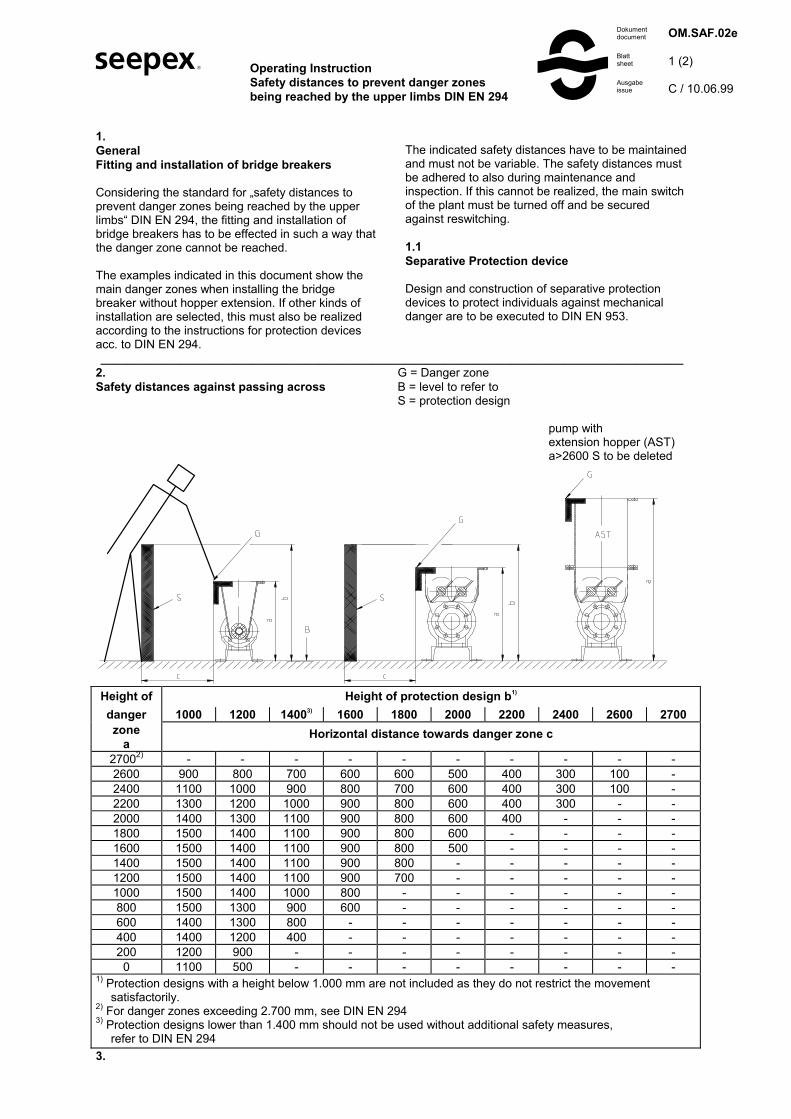
1. General Fitting and installation of bridge breakers Considering the standard for „safety distances to prevent danger zones being reached by the upper limbs“ DIN EN 294, the fitting and installation of bridge breakers has to be effected in such a way that the danger zone cannot be reached. The examples indicated in this document show the main danger zones when installing the bridge breaker without hopper extension. If other kinds of installation are selected, this must also be realized according to the instructions for protection devices acc. to DIN EN 294.
The indicated safety distances have to be maintained and must not be variable. The safety distances must be adhered to also during maintenance and inspection. If this cannot be realized, the main switch of the plant must be turned off and be secured against reswitching. 1.1 Separative Protection device Design and construction of separative protection devices to protect individuals against mechanical danger are to be executed to DIN EN 953.
________________________________________________________________________________________ 2. G = Danger zone Safety distances against passing across B = level to refer to S = protection design pump with extension hopper (AST) a>2600 S to be deleted
Height of
Height of protection design b1) danger 1000 1200 14003) 1600 1800 2000 2200 2400 2600 2700 zone
a Horizontal distance towards danger zone c
27002) - - - - - - - - - - 2600 900 800 700 600 600 500 400 300 100 - 2400 1100 1000 900 800 700 600 400 300 100 - 2200 1300 1200 1000 900 800 600 400 300 - - 2000 1400 1300 1100 900 800 600 400 - - - 1800 1500 1400 1100 900 800 600 - - - - 1600 1500 1400 1100 900 800 500 - - - - 1400 1500 1400 1100 900 800 - - - - - 1200 1500 1400 1100 900 700 - - - - - 1000 1500 1400 1000 800 - - - - - - 800 1500 1300 900 600 - - - - - - 600 1400 1300 800 - - - - - - - 400 1400 1200 400 - - - - - - - 200 1200 900 - - - - - - - - 0 1100 500 - - - - - - - -
1) Protection designs with a height below 1.000 mm are not included as they do not restrict the movement satisfactorily. 2) For danger zones exceeding 2.700 mm, see DIN EN 294 3) Protection designs lower than 1.400 mm should not be used without additional safety measures, refer to DIN EN 294 3.

s Operating Instruction Safety distances to prevent danger zones being reached by the upper limbs DIN EN 294
S
Dokument document
Blatt sheet
Ausgabe issue
OM.SAF.02e 2 (2) C / 10.06.99
Safety distances for performing work in openings or reaching through openings Danger zone (G) Danger by performing work in the area of rotating shafts. 3.1 Pump with extension hopper (AST), C inspection port (KIS) including safety switch (SHS) A safety switch (SHS) is attached to the inspection port (KIS). The plant operator has to incorporate the safety switch (SHS) in the electrical control before pump commissioning, so that the following components are disconnected and safeguarded against re-connection during opening of the inspection port (KIS): • Bridge breaker drive • Pump drive • Other drives projecting into the inside area It should only be possible to re-connect these components by the RESET key after the port has been closed. Additionally, any feed of liquids into the extension hopper should be disconnected immediately. After disconnection of the inspection port (KIS) the plant can be re-commissioned.
3.2 Pump including inspection port (RGD) C Prior to opening of the inspection port (RGD) the pump drive and the bridge breaker drive have to be disconnected and safeguarded against re-connection. After closing of the cleanout (RGD) the pump drive and the bridge breaker drive can be re-commissioned.
3.3 Pump including cover (DEK) In case that the cover (DEK) has to be opened for refilling, the pump drive has to be disconnected and be safeguarded against re-connection before. As an alternative the operator can install a safety switch to be incorporated in the electrical control. It should only be possible to re-connect the drive after having closed the cover.
C

Operating Instructions seepex Machine Transport and Intermediate Storage
Dokument document Ausgabe issue Blatt sheet
OM.TRA.01e B / 14.08.98 1 (1)
3. Transport and Intermediate Storage 3.1 Safety Precautions Employ appropriate transport means, hoists and tools when transporting and storing the machine, always observing the safety instructions. 3.2 Transport Depending on its weight, the seepex machine must be transported manually or with appropriate trans-port means. Comply with the transport instructions on the packing. 3.3 Unpacking The design of the packing is such that the equip-ment can be removed manually or, if demanded by the weight, by means of appropriate hoists. Any screw fittings between the machine and the packing must be undone. Comply with the attached information notices and symbols. 3.4 Intermediate Storage/Preservation Unless otherwise indicated in the data sheet, seepex machines are provided with preservation only for the duration of transport. If a long period of intermediate storage is foreseen before the machine is commissioned, it is necessary to pro-vide supplementary preservation. If necessary, the appropriate measures should be drawn up in consultation with seepex. Intermediate storage in extreme climatic conditions is permissible only for machine whose design is appropriate to the circumstances. If necessary, seepex must be consulted.
CAUTION Pumps of the range MAP If the period from supply and subsequent storage until the commissioning is more than 4 weeks, the hoses should be dismantled, refer to Point 7. 3.5 Protection against Environmental Influences To afford protection against environmental influences, the intermediate storage location must be dry, enclosed and free from frost.

� Operating InstructionsProgressive Cavity PumpDescription of the seepex Pump andAccessories
�Dokumentdocument
Blattsheet
Ausgabeissue
OM.DES.01e
1 (1)
A / 10.01.95
4.Description of the seepex Progressive CavityPump and Accessories
4.1General Description, Design and Mode of Operation
Like all progressive cavity pumps, seepex pumpsbelong to the rotating positive-displacement pumpfamily. The characteristic attribute of these pumps isthe special formation and arrangement of the twoconveying elements, namely the rotor and the stator.
The difference in the number of threads possessedrespectively by the rotor and stator produces achamber that opens and closes alternately in linewith the constant turning motion of the rotor, effectingthe continuous transportation of the conveyingproduct from the suction side to the pressure side.
The geometrical formation of the two conveyingelements combined with the constant contact thatexists between them result in sealing lines that effectan airtight seal between the suction and pressureside in every position of the eccentric screw, evenwhen the pump is stationary. The pump owes its highsuction capacity to thissealing between the suction and pressure sides.
4.2Mechanical Design
Please consult the sectional drawing, Point 9,for the mechanical design of the pump. The datasheet, Point 9, gives information on the design of thepump housing, stator, rotor and rotating components.
Refer to document OM. SEA. _ _, Point 9 forinformation on the design of the shaft seal.
The data sheet, Point 9, specifies details of thedesign of the drive engine. Further details aregiven in the appended manufacturer’s documents,Point 10.
4.3Accessories
Consult the data sheet in Point 9 for information.
4.4Dimensions, Weight
Consult the appended dimensional drawing,Point 9.
4.5Design Variants
Refer to the data sheet, Point 9, for the design of theseepex progressive cavity pump. Other designvariants are possible, whereby seepex must firstcheck whether a particular pump is suitable for theintended purpose.
4.6Operating Site Specifications
Operating site specifications are listed in the datasheet, Point 9. Details of the space required forinstallation, operation and maintenance are given inPoint 5.2.1.

� Operating InstructionsProgressive Cavity PumpAssembly and Installation
�Dokumentdocument
Blattsheet
Ausgabeissue
OM.INS.01e
1 (2)
A / 10.01.95
5.Assembly / Installation
5.1Mounting Tools / Hoists
No special tools are required for the assembly andinstallation of the pump.
The customer must check the dimensions and weightof the seepex progressive cavity pump to ascertainwhether the available hoisting apparatusis sufficient for the assembly and fitting of the pump.
5.2Initial Assembly
5.2.1Inspection Prior to Commencement of Assembly
5.2.1.1Location
The place of installation for the pump must con-formwith the site stated in the data sheet in Point 9. Anychange of location must be checked and approved byseepex.
5.2.1.2Space Requirements
Customers are responsible for determining thespace requirements; the following factors must betaken into consideration:
ì dimensions and weight of the machineì required transport and hoisting equipmentì possible piping layout with allowance for the space
allowing disassembly of the rotor as defined in5.2.1.3
ì freedom of movement to:operate the drive /speed regulationread speed and pressure indicatorsadjust a stator retensioning device, if fittedoperate a buffer fluid supply unit, if fitted
ì space required for lubrication / renewal oflubricants
ì disassembly of mechanical protective devices, e.g.V-belt or coupling protection
ì space required for handling the mounting tools,e.g. sufficient wall clearance
5.2.1.3Space Allowing Disassembly of Stator P
A specific space must be allowed for exchanging thestator. The required dimension "P" is indicated in theindex of these operating instructions or in theappended dimensional drawing, Point 9.
CAUTIONEnsure also that the pipe work can be dismounted atthis location too.
5.2.2Installation of the Fully Assembled Pump
• Installation in conformity with data sheetInstallation of the pump is permissible only inaccordance with the data sheet specifications andthe associated basic drawing, see Point 9. Anychange in the position must be checked andapproved by seepex.
• Tension-free mounting of pumpThis rule applies to pumps with and without drives,to versions with and without baseplate, formounting on the foundation or other bearingelements. The entire area of all bearing surfaces ofthe machine must rest on the ground. Anyunevenness must be corrected by appropriatesupports.
ì Correct seating of drivesAll drives have been aligned ready for operationand mounted by seepex. However, displace-mentsmay occur during transport or installation. For thisreason, check that the alignment and fastening ofthe drive and coupling are correct.
• Protective devicesOn completion of the assembly andinstallation work, immediately mountall safety and protective devices intheir proper locations and set them inoperation.

� Operating InstructionsProgressive Cavity PumpAssembly and Installation
�Dokumentdocument
Blattsheet
Ausgabeissue
OM.INS.01e
2 (2)
A / 10.01.95
5.2.3Protective and Controlling Equipment
Information on equipment of this nature, where fitted,is provided in the data sheet, Point 9. Consult theattached manufacturer’s specifications, Point 10, forinstructions on assembly and installation.
5.2.4Electric Connection of Electric Motorand Frequency Converter
The electric connections must beestablished in accordance with themanufacturer’s specifications,Point 10, as well as the safety speci-fications applying at the installation site.The mains voltage and frequency mustmatch the ratings indicated on the typeand rating plates.
• Switch on electric motor „direct-on-line“CAUTION
An increased starting torque is necessary dueto the clamping between the rotor and statorconveying elements. This means the electric motorsthat drive the progressive cavity pumps must alwaysbe switched on directly. As a rule, star-delta startupis not possible unless special arrangements havebeen made with seepex.
Three-phase cage motor
Delta connection Star connection
Terminalboard
low . . . high . . .. . . voltage indicated on rating plate
• Speed regulation via frequency inverterWhen progressive cavity pumps with frequency-controlled drives are started up problems may occurdue to unsuitable or wrongly set frequency inverters.For this reason we recommend the purchase of thecomplete drive, including frequency inverter, fromseepex, so that the frequency inverter can be tunedon the seepex test field along with a trial run.
Ensure that customer-supplied frequency inverterscomply with the starting torque and running powerspecified in the appended data sheet,Point 9.
CAUTIONConsult the appended document TI.FRU.01, seePoint 9, for further information on the electricconnection and the setting of frequency inverterand variable-speed motor.
5.2.5Piping
5.2.5.1Suction and Pressure Flanges
The position, nominal width and standard of thesuction and pressure flange of the progressive cavitypump are specified in the dimension drawing, Point9, and data sheet, Point 9. Always observe therotational direction and flow direction defined in Point6.2.5.
5.2.5.2Piping Dimensioning
CAUTIONThe pipe diameters on the suction and pressuresides must be dimensioned in accordance with thecustomer’s pressure-loss calculation in such a waythat the pressures specified in the data sheet, Point9, are not exceeded. The nominal width of thesuction pipe should at least match that of the pumpsuction flange.
5.2.5.3Residue-free Piping
CAUTIONPrior to starting up the pump, ensure that all pipelinesare free from foreign bodies. Installation residues(such as weld spatter, screws, steel chips etc.) willlead to damage of the seepex pump for whichguarantee claims will not be accepted.
5.2.5.4Tension-free Mounting
CAUTIONPipelines and other components requiring to beconnected with the pump must be mounted withoutstresses.
5.2.5.5Fluid Connections for Optional ExtrasConsult the data sheets, Point 9, for informationregarding the optional extras, if any, that are fitted.The technical description is given under Point 9.

Operating Instructions Progressive Cavity pump Commissioning/De-commissioning
Dokument document Ausgabe issue Blatt sheet
OM.COM.01e C / 24.10.03 1 (3)
6. Commissioning/De-commissioning 6.1 Engineering Data Details regarding all technical specifications and operating conditions are given in these operating instructions together with the data sheet, Point 9. To guarantee the correct assignment of documen-tation to pump, the commission number on the � cover sheet � and data sheet of these operating instructions must match the commission number stated on � the nameplate of the pump. 6.1.1 See Point 7.2.2 for Lubricant Chart 6.2 Preparation for Operation 6.2.1 Bearing 6.2.1.1 See Point 7.2.1.4 for pump bearing. 6.2.1.2 See manufacturer's documents, Point 10, for drive bearings. 6.2.2 Shaft Sealing See document OM.SEA.__. 6.2.3 Filling Up of Suction Side to Avoid Dry Running at Startup 6.2.3.1 General
CAUTION Before switching on the pump, fill the suction-sided pump casing with fluid so that the first rotations will lubricate the conveying elements immediately. A small quantity of fluid is sufficient for lubrication; the subsequent operation of the pump is self-priming, even if an air column up to the liquid level remains. 6.2.3.2 Pump with plastic rotor Pump with plastic rotating unit
CAUTION Important information about commissioning can be taken from the document OM.ROT.01.
6.2.4 Electric/Hydraulic Connections The connections are listed in the appended manufacturer's documents, Point 10. The risk of exposure to electrical hazards must be ruled out. Always observe the safety regulations valid at the site of installation.
6.2.5 Checking Direction of Rotation The rotational direction of the pump determines the flow direction of the conveying medium.
Flow direction
counter-clockwise
Flow direction
clockwise Prior to commissioning the rotational direction of the pump must be checked for compliance with the data sheet specification and the rotational direction arrow on the type plate of the pump. 6.3 Control and Monitoring Equipment Where applicable, please refer to the associated documents, Point 10, for information on commissioning. 6.3.1 Performance Check Any optional extras must be subjected to a performance check in conformity with the specifications by seepex or other manufacturers, see manufacturer's documents. 6.3.2 Setting Unless already performed in the factory, setting must be carried out in accordance with the appended manufacturer's specifications. Pay attention to the operating specifications in the data sheet.

Operating Instructions Progressive Cavity pump Commissioning/De-commissioning
Dokument document Ausgabe issue Blatt sheet
OM.COM.01e C / 24.10.03 2 (3)
6.4 Equipment for Protection of Persons Machines must be fitted with mechanical protective devices complying with DIN EN 809. � Moving or working parts must be
protected against accidental contact. � However, safety considerations
demand it be possible at all times to check without hindrance whether the shaft seal is fully functional. A protective guard is necessary in this area only if components are mounted on the rotating, smooth shaft.
� If pumps are operated with an open
suction flange/feed hopper, a suitable protective guard complying with DIN EN 294 must be mounted.
� Country-specific protective regu-lations
must be observed at the site of installation. Prior to activation of the pump, check the proper function of all protective equipment.
6.5 Commissioning 6.5.1 Initial Startup/Re-starting
CAUTION Every seepex progressive cavity pump is designed for the specific operating conditions documented in the data sheet. Commissioning is permissible only if the operating conditions conform with those indicated in the data sheet. Although the potential usages of the seepex pump are not confined to the specified operating conditions, any change in the original conditions must be checked and approved by seepex.
The right to make claims under the warranty agreement will be annulled if operating conditions are changed without prior approval by seepex.
6.5.2 Avoid Dry Running of Pump
CAUTION The dry running of a pump increases the friction between rotor and stator, quickly causing an unacceptably high temperature to develop on the inner surface of the stator. This overheating leads to burning of the stator material and the total failure of the pump. For this reason it is necessary to ensure that the suction-sided flow never dries up completely. If a continuous flow cannot be guaranteed for the plant, it is essential to fit the seepex dry running protection device TSE, available as an optional accessory.
6.5.3 Check Pressure at Suction and Pressure Flanges 6.5.3.1 Safeguard Pump Against Excessive Pressure at the Suction Flange The seepex pump is designed to operate with the pressure at the suction flange (suction head or inlet pressure) specified in the data sheet. Deviating pressure conditions may lead to the failure and/or destruction of the shaft seal or entire pump. For this reason the suction pressure specified in the data sheet must be guaranteed. Appropriate monitoring devices are oil-filled contact mano-meters that deactivate the pump.
6.5.3.2 Safeguard Pump Against Excessive Pressure at the Pressure Flange The seepex pump operates according to the positive displacement principle. Operation of the pump against an excessive pressure caused by closed valves, by high pressure losses in the piping or by product sedimentation will lead to the destruction of the pump, drive, pipe work and/or downstream equipment. Every progressive cavity pump must therefore be protected against overpressure. Safety valves with bypass pipes or oil-filled contact manometers that disactivate the pump are appropriate protective devices.
6.5.4 Drive Engine Consult the attached manufacturer's operating instructions, Point 10, for information on commissioning the drive engine.

Operating Instructions Progressive Cavity pump Commissioning/De-commissioning
Dokument document Ausgabe issue Blatt sheet
OM.COM.01e C / 24.10.03 3 (3)
6.5.5 Establish Clear Passage Through Pipelines
CAUTION To prevent damage to the pump the unhindered flow of liquid must be guaranteed between the points of entry to and exit from the pipeline. For this reason, open all relevant valves etc. prior to activation of the pump. 6.6 De-commissioning 6.6.1 De-activation The electric connections must be switched off and protected against accidental re-activation. Observe the safety regulations applying to the plants.
6.6.2 Stationary Pump The pump and all optional equipment must be provided with the following protection modes while at a standstill: - Frost protection - Protection against solid particle deposits - Protection against sedimentation of the medium - Corrosion protection for parts in contact with
the medium We recommend that the pipeline and pump be emptied for the duration of the plant standstill. Following evacuation, the pump should be preserved. 6.6.3 Evacuation of the Pump The pipeline must be evacuated on the suction and pressure side or shut-off directly behind the pump connections. Drain any residual liquid in the pump casing by opening/ removing the screwed sealing plugs (705) and (502), sealing rings (706) and (503).
CAUTION Coated casings or housings without screw plug have to be drained by the connection branch (SAG and DRS). Refer to the data sheet and the sectional drawing of the associated operating instruction for information on the pump design. Conveying medium residues always remain in the rotor/ stator chambers and may run out during transport or disassembly of the pump. When conveying aggressive or hazardous media, therefore, wear appropriate protective clothes during all installation work.
6.6.4 Disassembling the Pump Dismantle the pipe work by removing the flange bolts (SCH) and flange seals (DFL) or the threaded connections (G). Disassemble the pump together with the baseplate (GPU) or, as applicable, without the baseplate (GPU) following removal of the bolts (SCH) at the pump feet. Block-design pumps with direct flange-mounted drive engine are liable to become unstable during disassembly. Stability can be restored by propping up the drive engine.
6.6.5 Preservation/Storage The pump must be preserved prior to storage. Appropriate preservation measures must be agreed with seepex. Always state the pump commission number when making inquiries.
s Operating Instructions Progressive Cavity Pump Service and Maintenance
S
Dokument document
Blatt sheet
Ausgabe issue
OM.MAI.04e 1 (4) A / 13.04.95
These operating instructions are valid for range BT size 05-24, 1-6, 1-12, 2-6L to 300-6L 7. Service and Maintenance Contents 7.1 General Instructions 7.2 Service and Inspection 7.3 Dismantling 7.4 Re-assembly The sectional drawing and parts list relevant for Points 7.3 and 7.4 can be found in Point 9. 7.1 General Instructions A requirement for the reliable operation of any pump is service and maintenance in compliance with instructions. Maintenance personnel must therefore have access to these operating instruc-tions and adhere to them meticulously. seepex will accept no liability for damages arising through non-observance of these operating instructions. 7.2 Maintenance and Inspection 7.2.1 Lubrication 7.2.1.1 Rotor and Stator The rotor and stator are lubricated by the conveying medium. 7.2.1.2 Shaft Sealing Consult document OM.SEA.__ Point 9 for information on lubricating the shaft seal. 7.2.1.3 Pin Joint The pin joints are filled with special grease and lubricated for the expected duration of service. The seepex joint grease specified in the index of these operating instructions should be used exclusively for any required maintenance work.
CAUTION Usage of other grease types will lead to premature joint failure and render invalid any right to claims under guarantee.
7.2.1.4 Bearing of the Pump/Drive Engine The bearing of the rotating pump parts is effected by the drive engine. Lubrication instructions are therefore included in the appended drive engine operating instructions, Point 10. 7.2.2 Lubricant Filling Levels Details are specified in the index. 7.2.3 Drives and Optional Extras For maintenance and inspection specifications, see the appended manufacturer's documents, Point 10. 7.2.4 Supervision during Operation 7.2.4.1 Shaft Sealing See document OM.SEA.__ Point 9. 7.2.4.2 Optional Extras These must be monitored in accordance with the separate documents, Point 9/Point 10. 7.2.4.3 Drive Engines These must be monitored in accordance with the separate manufacturer's documents, Point 10. 7.2.5 Preventive Measures To avoid the expenses incurred by lengthy stop periods of the pump, seepex recommends the acquisition of a set of wearing parts and a set of gaskets. The contents are listed in the document OM.WPS.04, Point 9.
s Operating Instructions Progressive Cavity Pump Service and Maintenance
S
Dokument document
Blatt sheet
Ausgabe issue
OM.MAI.04e 2 (4) A / 13.04.95
7.3 Dismantling the seepex Progressive Cavity Pump Tools are required for dismantling and re-assembly. These tools are listed in Point 9 of the document OM.SPT.01. The stator (601) and the rotating pump parts can be exchanged in site. The rotating pump parts can be dismantled as a complete rotating unit (RTE) (Point 7.3.4) or as individual components (Point 7.3.5). Before commencing the dismantling of pump parts, safeguard the pump against tipping over or falling down by fastening it at the lantern (200).
7.3.1 Pressure Flange (700) - Dismantling Prior to dismantling see Point 7.3.2 Before dismantling the stator (601), provide it with a support (S) to prevent it from falling.
7.3.2 Stator (601) - Dismantling • Maintenance tip:
Disassembly of the stator can be made consider-ably easier by first moistening the inner surface of the stator with antiseize agent (soft or liquid soap). Before removing the pressure flange (700), pour the antiseize agent into the opening between rotor and stator on the pressure flange side. Several clockwise (see Point 6.2.5) revolutions of the rotor will then distribute the antiseize agent over the inner surface of the stator and reduce the friction between rotor and stator considerably.
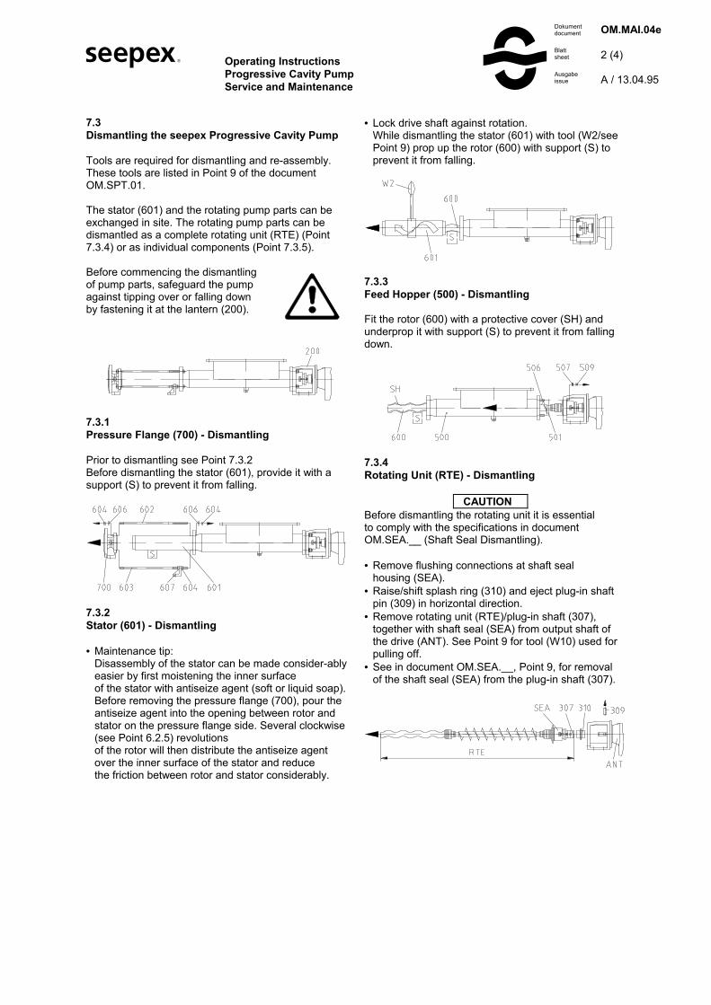
• Lock drive shaft against rotation. While dismantling the stator (601) with tool (W2/see Point 9) prop up the rotor (600) with support (S) to prevent it from falling.
7.3.3 Feed Hopper (500) - Dismantling Fit the rotor (600) with a protective cover (SH) and underprop it with support (S) to prevent it from falling down.
7.3.4 Rotating Unit (RTE) - Dismantling
CAUTION Before dismantling the rotating unit it is essential to comply with the specifications in document OM.SEA.__ (Shaft Seal Dismantling). • Remove flushing connections at shaft seal
housing (SEA). • Raise/shift splash ring (310) and eject plug-in shaft
pin (309) in horizontal direction. • Remove rotating unit (RTE)/plug-in shaft (307),
together with shaft seal (SEA) from output shaft of the drive (ANT). See Point 9 for tool (W10) used for pulling off.
• See in document OM.SEA.__, Point 9, for removal of the shaft seal (SEA) from the plug-in shaft (307).

s Operating Instructions Progressive Cavity Pump Service and Maintenance
S
Dokument document
Blatt sheet
Ausgabe issue
OM.MAI.04e 3 (4) A / 13.04.95
7.3.5 Rotating Pump Parts - Dismantling 7.3.5.1 Rotor (600), Auger feed screw (400) Detach the rotor (600) and auger feed screw (400) from the plug-in shaft (307) by dismantling the joint (G) in accordance with Point 7.3.6.
7.3.5.2 Plug-in Shaft (307) The plug-in shaft (307) is removed in the same way as the rotating unit (RTE), see Point 7.3.4.
7.3.6 Dismantling of Joint see document OM.PJT.02, Point 1. 7.3.7 Shaft Sealing See document OM.SEA.__, Point 9 for information on dismantling the shaft sealing. 7.3.8 Lantern (200)/Drive (ANT) - Dismantling
7.4 Re-assembly Before commencing the re-assembly, fasten the lantern (200) in such a way that it cannot tip over or fall down during the re-assembly of the drive and all pump components.
7.4.1 Lantern (200)/Drive (ANT) - Assembly Clean flange bearing surfaces (FLS), centering diameter and output pivot of the drive (ANT).
7.4.2 Rotating Unit (RTE) - Re-assembly The rotating unit (RTE) has been assembled in accordance with the description in document OM.PJT.02. • Mount shaft seal (SEA) on plug-in shaft (307) in the
way described in document OM.SEA __, see Point 9.
• Moisten splash ring (310) and plug-in shaft (307) with joint grease (see index for type) and slide splash ring (310) onto plug-in shaft (307), observing the fitting position of the splash ring, (see writing on the splash ring).
• Apply antiseize graphite petroleum to the output pivot of the drive (ANT) and slide on the rotating unit (RTE). Insert plug-in shaft pin (309) horizontally.
• Splash ring position (310) The collar of the splash ring should be mounted at a distance of 0.5 mm from the lantern (200).

s Operating Instructions Progressive Cavity Pump Service and Maintenance
S
Dokument document
Blatt sheet
Ausgabe issue
OM.MAI.04e 4 (4) A / 13.04.95
7.4.3 Rotating Pump Parts - Re-assembly Prepare main components: Prepare rotor (600), auger feed screw (400) and plug-in shaft (307) as described in document OM.PJT.02, Point 2. to 2.3 Joint (G) re-assembly as described in document OM.PJT.02, Point 3.
7.4.4 Feed Hopper (500), Casing Gasket (501) - Re-assembly Fit protective cover (SH) on rotor (600) and prop it up with support (S).
7.4.5 Stator (601) - Assembly / Re-assembly Maintenance tip: Disassembly of the stator can be facilitated con-siderably by first moistening the inner surface of the stator with antiseize agent (soft or liquid soap). Before removing the pressure flanges (700), pour the antiseize agent into the opening between rotor and stator on the pressure flange side. Several clockwise (see Point 6.2.5) revolutions of the rotor will then distribute the antiseize agent over the inner surface of the stator and reduce the friction between rotor and stator considerably. Lock drive (ANT) shaft against rotation. Using tool (W2/see Point 9), turn stator (601) clockwise and simultaneously push it over rotor (600), propping up stator with support (S) at the same time.
7.4.6 Pressure Flange (700) - Assembly
CAUTION Tighten tie bolts (602 and 603) in equally.

� Operating InstructionsProgressive Cavity PumpPin Joint Assembly
�Dokumentdocument
Blattsheet
Datumdate
OM.PJT.02e
1 (3)
B / 27.01.97
1.Dismantling of Joint
1.1Holding Band (406, 407) and Universal JointSleeve (405)
Cut through loop (SCL) of the holding bands (406and 407) with a metal saw.
Wear protective goggles whensqueezing out the two halves ofthe holding band loop (SCL).
Remove holding bands (406,407). Pull universal jointsleeve (405) off joint.
1.2Retaining Sleeve (401) - Dismantling
- For rotors and plug-in shafts made of hardened and unhardened materials, knock back retaining sleeve (401) with tool/chisel (WM).
- For rotors made of synthetic material, release set screw (426).
1.3Separation of Joint
Eject coupling rod pin (402). Position couplingrod (400) at the correct angle (A) and, using tool(W5/see Point 9), drive both guide bushes (403)outwards.This releases the coupling rod (400), whichcan then be extracted.
CAUTIONTo guarantee the proper function of the joints, itis advisable to renew the coupling rod pins (402),guide bushes (403) and coupling rod bushes (404)all at the same time.
1.4Coupling Rod Bushes (404) - Dismantling
CAUTIONAs a precaution against incorrect re-assembly ofcoupling rod bushes (404), we recommend theemployment of coupling rods (400) whose couplingrod bushes (404) have been pressed in by seepex.
The coupling rod bush (404) is pushed out of thecoupling rod (400) with tools (W4 and W14/see Point9).
2.Prepare main components for Re-assembly
2.1Rotor (600) - Preparation for Joint Assembly
First remove any burr, flaws or similar defects fromthe rotor, then clean it.
2.2Coupling Rod (400) - Preparation for the JointAssembly
CAUTIONAs a precaution against the incorrect re-assembly ofcoupling rod bushes (404), we recommend the em-ployment of coupling rods (400) whose bushes (404)have been pressed in by seepex.
Press in new coupling rod bushes (404 using tool(W4) and (W14/see Point 9).

� Operating InstructionsProgressive Cavity PumpPin Joint Assembly
�Dokumentdocument
Blattsheet
Datumdate
OM.PJT.02e
2 (3)
B / 27.01.97
• Position of coupling rod bush (404)
correct incorrectpressed in centrically pressed in eccentrically
result: joint fracture
Marking notches in (MK) in A-A axispermissible rotation 1,5°
correct incorrectpressed into A-A axis pressed in rotated
result: joint fracture
2.3Plug-in Shaft (307) - Preparation for JointAssembly
Remove any burr, flaws or similar defects from theplug-in shaft (307), then clean it.
3.Joint - Re-assembly
CAUTIONTo guarantee the proper function of the joints, itis advisable to renew the coupling rod pins (402),guide bushes (403) and coupling rod bushes (404)all at the same time.
• Joint head on rotor (600) and plug-in shaft (307)- Press guide bushes (403) in by only 2/3 of their
length using tool (W4/see Point 9)- Fill joint head with joint grease (098), see index for
special grease- Slip on joint sleeve (401)
• Coupling rod (400)Slide holding bands (406/407).Moisten inner surface of universal joint sleeve(405) with joint grease (see index for specialgrease) and slide it.Push coupling rod (400) into joint head.Push in coupling rod pin (402).
• Guide bush (403)Press in with tool (W5/see Point 9)
• Retaining sleeve (401)
• Securing of retaining sleeveFor drive shafts, plug-in shafts and rotors madeof unhardened materials such as St 70, AISI 304,AISI 316, Hastelloy C, secure 2 x 180° offsetindents, with tool/centre punch (WK)

� Operating InstructionsProgressive Cavity PumpPin Joint Assembly
�Dokumentdocument
Blattsheet
Datumdate
OM.PJT.02e
3 (3)
B / 27.01.97
For rotors made of hardened materials such as toolsteel (AISI D6), 1.2842, secure 2 x 180° offsetindents with tool/centre punch (WK)
- For rotors made of synthetic material, secure using set screw (426). During this process, point of set screw presses into the synthetic surface (X). Set screw (426) is medium strengh secured by screw locking device /adhesive.
• Universal joint sleeve (405)Remove air from interior of joint with tool/screwdriver (WS).
• Holding bands re-assemblyMount holding bands (406 and 407) using tool(W3/see Point 9) as described in documentOM.HBD.01e.

� Operating InstructionsProgressive Cavity PumpHolding Band Re-assembly
�Dokumentdocument
Blattsheet
Ausgabeissue
OM.HBD.01e
1 (2)
A / 23.02.95
Holding Band (HBD) - Assembly
Tools required for the re-assembly, see documentOM.STP.01, Point 9.
• Prepare holding band
Only prefabricated double-band holding bandsshould be used. The diameter (∅) and in particularthe breadth (b) of the holding band is matched to theuniversal joint sleeve.
• Test holding band
The bent holding band (HBD) must fit against theholding band loop (SCL), if necessary applypressure with the tool/pliers (WZ).
• Assembly of holding band
Insert holding band in tool (W3/ see Point 9). Holdfree end of holding band with control lever (EX),turn crank (KU) until the holding band is strainedand fitting against the holding band loop (SCL).Carefully contract holding band until it fits insidethe circular groove of the universal joint sleeve.
• Correct holding band tension (HBD)
CorrectHolding band(HBD) hasslightly con-tracted outerform of univers-al joint sleeveand is stuck inposition.
IncorrectHolding band(HBD) is tooslack and liableto slip.
IncorrectHolding band(HBD) is too tight.Universal jointsleeve will bedamaged/shearedoff.
• Folding back the holding band (HBD)
Slowly swivel mounting tool upward by 60°, at thesame time slackening the crank (KU) byapproximately one half revolution. Swivel cuttinglever (SH) forward until the pressure plate fitsagainst the holding band loop (SCL).
• Shearing off holding band (HBD) made of materialAISI 304 and AISI 316
A blow with the palm of the hand against thecutting lever (SH) causes the end of the holdingband behind the loop (SCL) to be folded back andsheared off. If the holding band on the sheared offside is slightly raised as a result, it must bestraightened carefully.
CAUTIONNever tap or hammer against the loop of theholding band (SCL), otherwise damage to theuniversal joint sleeve may occur.
• Shearing off holding band (HBD) made of HastelloyC
The high strength of this material makes it impossible to shear off the holding band (HBD) with the cutting lever (SH). Once the end of the holding band is folded back, cut off the holding band (HBD), file off projecting edges and remove burr.

� Operating InstructionsProgressive Cavity PumpHolding Band Re-assembly
�Dokumentdocument
Blattsheet
Ausgabeissue
OM.HBD.01e
2 (2)
A / 23.02.95
• Check after mounting of holding band
The holding band must run all the way round thegroove of the universal joint sleeve.
The holding band (HBD) must be bent back andsheared off at the holding band loop (SCL) in such away that the holding band (HBD) is unable to slipback through the holding band loop (SCL). If this hasnot been accomplished, then the holding band(HBD) must be replaced by a new one.
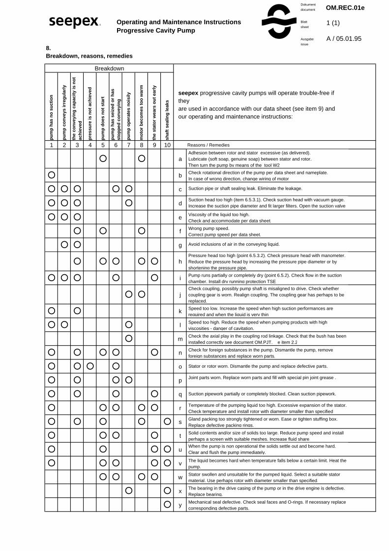
8.Breakdown, reasons, remedies
Breakdown
pu
mp
has
no
su
ctio
n
pu
mp
co
nve
ys ir
reg
ula
rly
the
con
veyi
ng
cap
acit
y is
no
t ac
hie
ved
pre
ssu
re is
no
t ac
hie
ved
pu
mp
do
es n
ot
star
t
pu
mp
has
sei
zed
or
has
st
op
ped
co
nve
yin
g
pu
mp
op
erat
es n
ois
ily
mo
tor
bec
om
es t
oo
war
m
the
stat
or
wea
rs o
ut
earl
y
shaf
t se
alin
g le
aks
1 2 3 4 5 6 7 8 9 10 Reasons / Remedies
� � a
� b
� � � � � c
� � � � d
� � � e
� � � f
� � g
� � � � � h
� � � � � i
� � j
� � k
� � � l
� m
� � � � � n
� � � � o
� � � � p
� � � � q
� � � � � r
� � � � � s
� � � � t
� � � � u
� � � � � v
� � � � w
� � x
� y
seepex progressive cavity pumps will operate trouble-free if they are used in accordance with our data sheet (see item 9) and our operating and maintenance instructions:
Check rotational direction of the pump per data sheet and nameplate. In case of wrong direction, change wiring of motor.
Suction pipe or shaft sealing leak. Eliminate the leakage.
Suction head too high (item 6.5.3.1). Check suction head with vacuum gauge. Increase the suction pipe diameter and fit larger filters. Open the suction valve
Viscosity of the liquid too high. Check and accommodate per data sheet.
Wrong pump speed.Correct pump speed per data sheet.
Avoid inclusions of air in the conveying liquid.
Pressure head too high (point 6.5.3.2). Check pressure head with manometer. Reduce the pressure head by increasing the pressure pipe diameter or by shortening the pressure pipe.
Pump runs partially or completely dry (point 6.5.2). Check flow in the suction chamber. Install dry running protection TSE.
Check coupling, possibly pump shaft is misaligned to drive. Check whether coupling gear is worn. Realign coupling. The coupling gear has perhaps to be replaced.
Speed too low. Increase the speed when high suction performances are required and when the liquid is very thin.
Speed too high. Reduce the speed when pumping products with high viscosities - danger of cavitation.
Check the axial play in the coupling rod linkage. Check that the bush has been installed correctly see document OM.PJT.__e item 2.2
Check for foreign substances in the pump. Dismantle the pump, remove foreign substances and replace worn parts.
Stator or rotor worn. Dismantle the pump and replace defective parts.
Joint parts worn. Replace worn parts and fill with special pin joint grease .
Suction pipework partially or completely blocked. Clean suction pipework.
Temperature of the pumping liquid too high. Excessive expansion of the stator. Check temperature and install rotor with diameter smaller than specified.
Gland packing too strongly tightened or worn. Ease or tighten stuffing box. Replace defective packing rings.
Solid contents and/or size of solids too large. Reduce pump speed and install perhaps a screen with suitable meshes. Increase fluid share.
When the pump is non operational the solids settle out and become hard. Clear and flush the pump immediately.
The liquid becomes hard when temperature falls below a certain limit. Heat the pump.
Stator swollen and unsuitable for the pumped liquid. Select a suitable stator material. Use perhaps rotor with diameter smaller than specified.
The bearing in the drive casing of the pump or in the drive engine is defective. Replace bearing.
Mechanical seal defective. Check seal faces and O-rings. If necessary replace corresponding defective parts.
Adhesion between rotor and stator excessive (as delivered). Lubricate (soft soap, genuine soap) between stator and rotor. Then turn the pump by means of the tool W2 .
OM.REC.01e
1 (1)
A / 05.01.95
Operating and Maintenance InstructionsProgressive Cavity Pump
Dokument
document
Blatt
sheet
Ausgabe
issue
� �

Operating Instructions seepex Machine Auxiliary documentation
Dokument document Ausgabe issue Blatt sheet
OM.ACC.01e A / 13.01.95 1 (1)
9. Auxiliary seepex documentation


Stückliste Baureihe BT Baugrössen 05-24, 1-6, 1-12,1-24, 2-6L...202-6L Schnittzeichnung Nr. 065-002 B1
Dokument document Ausgabe issue Blatt sheet
SL.065.002def B / 19.11.02 1 (1)
d e f Stückliste Baureihe BT Parts list range BT Liste des pièces série BT Baugrössen sizes tailles Schnittzeichnung Nr. sectional drawing No. plan no. Benennung denomination désignation
Stck. Pos. Stck. / Pos. Qty. / item Qté. / Poste 1 200 Laterne lantern lanterne 2 202 Halbrundkerbnägel round head grooved pins rivet 1 203 Typenschild type plate plaque signalitique 4 210 6kt-Schraube hexagon bolt vis 211 6kt-Schraube hexagon bolt vis 4 212 Federring spring washer rondelle frein 4 213 6kt-Mutter hexagon nut écrou 1 307 Steckwelle plug-in shaft arbre à broche 1 309 Steckwellenbolzen plug-in shaft pin cheville pour arbre à broche 1 310 Spritzring splash ring bague de projection 1 400 Transportschnecke auger feed screw vis transporteuse 2 401 Gelenkhülse retaining sleeve douille d'articulation 2 402 Kuppelstangenbolzen coupling rod pin axe d'articulation 4 403 Führungsbuchse guide bushing douille de guidage 2 404 Kuppelstangenbuchse coupling rod bushing chemise d'axe 2 405 Manschette universal joint sleeve manchette 2 406 Halteband holding band collier de serrage 2 407 Halteband holding band collier de serrage 1 500 Einlauftrichter feed hopper trémie d'entrée 1 501 Sauggehäusedichtung casing gasket étanchéité du carter d'aspiration 1 502 Verschlussschraube screwed plug bouchon de vidange 1 503 Dichtring sealing ring joint d'étanchéité 4 506 Stiftschraube stud bolt boulon fileté 4 507 Fächerscheibe fan type lock washer rondelle à dents chevauchantes extérieures 4 509 6kt-Mutter hexagon nut écrou 1 600 Rotor rotor rotor 1 601 Stator stator stator 2 602 Spannschraube tie bolt tirant 2 603 Spannschraube tie bolt tirant
12 604 6kt-Mutter hexagon nut écrou 12 606 Scheibe washer rondelle 1 607 Stützbock trestle pied 1 700 Druckstutzen pressure branch bride de refoulement 1 705 Verschlussschraube screwed plug bouchon de vidange 1 706 Dichtring sealing ring joint d'étanchéité 098 seepex Gelenkfett seepex joint grease seepex graisse d´articulations Typ und Füllmenge siehe Angaben im for type and filling quantity voir sommaire pour type et quantité Inhaltsverzeichnis der zur Pumpe refer to index of operating gehörenden Betriebsanleitung instruction belonging to pump
Verschleissteile und Dichtungen: Wear parts and sealings Pièces d´usure et étanchéités siehe Dokument OM.WPS.04d refer to document OM.WPS.04e voir document OM.WPS.04f Werkzeuge: Tools: Outils: Für Demontage und Wiedermontage required for disassembly and Requis pour le démontage erforderlich siehe Dokument OM.SPT.01 reassembly, refer to document OM.SPT.01 et le rémontage, voir document OM.SPT.01
versetzt gezeichnet drawn displaced plan separé Wellenabdichtung siehe shaft sealing see Dispositif d'etanchéité d'arbre Schnittzeichnung sectional drawing voir vue éclatée Gleitringdichtung mechanical seal garniture mécanique

� Shaft Sealing-DesignGland Packingseepex Code A
�Dokumentdocument
Blattsheet
Ausgabeissue
OM.SEA.Ae
1 (1)
A / 13.01.95
1.Safety for Shaft Sealings(in compliance with DIN EN 809)
Sufficient precautions must be taken to preventthe emergence into the atmosphere of any leakageconstituting a hazard due to its toxicity, explosive-nessor combustibility. The leakage must be dis-posed of ata safe location. Always pay due regard to theapplicable national standards and specifica-tions.
2.Shaft Sealing
2.1Operating Conditions
The permissible operating conditions and materialcombination are matched with the particularapplication in each case and are indicated in the datasheet of the associated pump.
2.2Design
• standard• 6 packing rings
associated operating instructions OM.SEA.01e

� Operating InstructionsShaft Sealing
�Dokumentdocument
Blattsheet
Ausgabeissue
OM.SEA.01e
1 (2)
A / 12.01.95
Gland Packing seepex Code A, C, E, F, S, V
1.Commissioning
1.1Adjusting the Gland Packing
When commissioned the factory-set gland packing isonly slightly tightened. For this reason, the packingmust be adjusted on-site to suit the prevailingoperating conditions.
1.2Gland Packing at Overpressure in SuctionChamber
50-100 drops per min. leakage is permissible atstartup until the packing material has settled (duration:c. 10-15 min.). Following the settle time, the leakagemust be reduced to 1-10 drops per min. by uniformlytightening the gland stuffing box. Leaking fluid drainsinto the drip pan, lantern and/or drive housing and carried off via a threaded drilling.
1.3Gland Packing at Partial Vacuum in SuctionChamber
With the low pre-set tightening level, the gland packingrequires c. 10-15 minutes before the packing materialsettles. After this time, tightenthe gland stuffing box uniformly until no more airis drawn in from the atmosphere.
2.Monitoring during Operation
2.1Checking for Leaks
Gland packings must be checked for leaks at regularintervals while the pump is running. In the case ofexcessive leakage (overpressure in suction chamber)or intake of air (partial vacuum in suction chamber),the gland stuffing box (302) must be tightened until thepermissible leakage rate is achieved see Point 1.2 or1.3. If the gland packing has been tightened to suchan extent that the gland stuffing box (302) fits upagainst the gland housing (300), it is neces-sary to fita new packing ring (301). If following tightening of thenew packing ring the gland stuf-fing box again fits upagainst the gland housing, then it is advisable toreplace the entire gland packing. Timely renewal of thepacking will largely rule out the incidence of shaftwear.
2.2Operating Errors and Consequences
Gland packings are intended to limit, but not pre-vent,the escape of the medium. Some leakageis necessary to reduce friction and carry off theassociated friction heat.
Correct:lubrication byliquid andantiseize agent
Incorrect:no liquidlubrication dueto excessivestuffing boxpressure;impregnation issqueezed out.
Consequence:dry running,burning of thepacking. Severeshaft wear leadingto heavy leakage.

� Operating InstructionsShaft Sealing
�Dokumentdocument
Blattsheet
Ausgabeissue
OM.SEA.01e
2 (2)
A / 12.01.95
3.Service and Maintenance
3.1Renewing Gland Packing
The tool (W1/see Point 9) should be used to removethe individual packing rings (301). Before re-fitting therings, clean the gland area and replace any damgedshafts.See Point 4.2 for instructions on re-fitting the packingrings (301).
4.Dismantling / Re-mounting
4.1Dismantling
Following the dismantling of the rotating unit (RTE) inthe manner described in OM.MAI.01 Point 7.3.5, cleanthe plug-in shaft (307) and remove any pro-jectingedges and burring that could damage the shaft sealingelements.
Remove shaft sealing (SEA) from the plug-in shaft.
4.2Re-assembly
CAUTIONAs a basic rule, only packing materials conforming tothe operating conditions as well as suitable packingdiameters and lengths should be used.
CAUTIONPlease refer to the added document OM.SEA.__e“shaft sealing design“ for details of the layout of any sealcage, grease lantern and/or thrust collar, if existent, aswell as connection possibilities in the gland housing.
Fit the packing rings (301) with cut ends offset by 90°.Using the gland stuffing box (302), insert the individualrings uniformly into the gland packing chamber (neveruse a pointed implement, otherwise damage to theshaft could result and the packing material becomedeformed).
� Operating InstructionSingle-Acting Mechanical Seal
�Dokumentdocument
Blattsheet
Ausgabeissue
OM.SEA.02e
1 (2)
A / 10.02.95
1.General
• Please take the appertaining drawing fromrespective pump data sheet.
• The mechanical seal is suitable for the operatingconditions indicated in the pump data sheet.Modifications are only admissible after the customerhas consulted with seepex. Additionally, attentionmust be paid to the manufacturer’s operatingmanual.
2.Safety
Any mode of operation impairing the operating safetyof the mechanical seal has to be avoided.
The operator is advised to consider the possibleeffects on the environment which could be caused bya defective mechanical seal and what additionalmeasures must be taken to protect the environmentand the public.
The pump must be mounted and operated in sucha way that operation with a defective mechanical sealwill not result in injury or harm to the public and thatany leakage can be safely and properly dealt with.
Mechanical seals are often used to seal hazardousmaterial (chemicals, drugs, etc.). It is essential thatrules pertaining to the handling of hazardous materialsare adhered to.
Modifications effected by the customer himself andchanges influencing the safety of the mechanical sealare not allowed.
3.Emissions
A mechanical seal is a dynamic seal and leakage isunavoidable.
ATTENTIONComponents that may contact leakage must beresistant to corrosion or be protected accordingly.
Mechanical seal leakage must be drained in a safeand proper manner.
4.Flushing or circulation of single-acting mechanicalseals
Single-acting mechanical seals contacting the con-veying liquid require no additional flushing or acirculation pipe because sufficient flushing and heatexchange occurs around the seal due to the conveyingliquid.
However, in particular cases, a direct flushing pipe canbe installed into the flushing connection on themechanical seal housing.
5.Commissioning
Regardless of the pump's operating status, the con-veying medium to be sealed must always be in liquidform at the mechanical seal. This particularly appliesto the pump's commissioning and its placing out ofservice.
6.Maintenance
When operating the pump according to the instruc-tions, no maintenance is required.
7.Disassembly / Reassembly
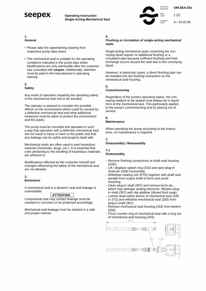
7.1Disassembly
- Remove flushing connections at shaft seal housing(SAE).
- Lift / displace splash ring (310) and eject plug-inshaft pin (309) horizontally.
- Withdraw rotating unit (RTE) together with shaft sealparallel from output shaft of drive and avoidchocking.
- Clean plug-in shaft (307) and remove burrs etc.,which may damage sealing elements. Moisten plug-in shaft (307) with slip additive (diluted fluid soap).
- Loosen axial safety device of mechanical seal (330or 372) and withdraw mechanical seal (330) fromplug-in shaft (307).
- Remove mechanical seal housing (333) from lantern(200).
- Press counter-ring of mechanical seal with o-ring outof mechanical seal housing (333).

� Operating InstructionSingle-Acting Mechanical Seal
�Dokumentdocument
Blattsheet
Ausgabeissue
OM.SEA.02e
2 (2)
A / 10.02.95
7.2Reassembly
ATTENTIONMechanical seals are precision parts of high quality.Therefore, the installation must be effected with care.Gentle handling and extreme neatness are essential.
- Clean mechanical seal housing (333)- Evenly press counter-ring with o-ring into mecha-
nical seal housing (333). To facilitate assembly, theo-ring should be moistened with a lubricant (dilutedfluid soap).
ATTENTION- Oil or grease must not be used to facilitate
assembly.- Install mechanical seal housing (333) to lantern
(200) and onsure correct position of flushingconnections.
- Remove plug-in shaft (307), burrs and roughnessand clean the unit.
- Check / adjust set dimension of mechanical seal onplug-in shaft (307). Moisten plug-in shaft (307) andelastomer parts of mechanical seal with lubricant(diluted fluid soap).
- Slip mechanical seal onto plug-in shaft (307) as faras set ring.
- Lubricate drive shaft (ANT) with antiseize graphitepetroleum.
- Moisten splash ring (310) and plug-in shaft (307)with pin joint grease, (for type, please see index) andslip splash ring (310) onto output shaft of drive. Noteinstallating position of splash ring and refer todescription on splash ring.
- Move rotating unit (RTE) through mechanical sealhousing (333) and splash ring (310) and slip splashring (310) onto output shaft of drive (ANT). Push inplug-in shaft pin (309) in horizontal position.
- Position of splash ring:Collar of splash ring shall be fitted in a distance ofabout 0.5 mm to lantern (200).

� Operating InstructionsProgressive Cavity PumpWearing Parts and Gaskets
�Dokumentdocument
Blattsheet
Ausgabeissue
OM.WPS.04e
1 (1)
B / 11.05.98
Wearing parts and gaskets
Sizes: 05-24, 1-6, 1-12, 2-6L to 300-6LRange: BT
To avoid the expenses incurred by lengthy stop periods of the pump, seepexrecommend the acquisition of a set of wearing parts and a set of gaskets.The table below shows the contents of these sets.
Item number acc. to sectionaldrawing of pump and partslist
Part designation Number
Rotor 1 600
Stator 2) 1 1 601
Universal joint sleeve 2 405
Coupling rod pin 2 402
Guide bush 2) 4 403
Auger feed screw / withcoupling rod bush 1/2 400 / 404
Coupling rod bush 2) 2 404
Casing gasket 1 501
Holding band, small 2) 2 407
Holding band, large 2) 2 406
Packing ring set 2) 1 1 301
flushing ring 1 1 311
Mechanical seal 1 330
Sealing ring 2 503, 706
Splash ring 1 310
O-ring/cleanout - -
Plug-in shaft 2) 1 307
Special joint grease 0981 cart. 300 gr (c. 315cm³) grease quan-tity per pin joint, see tech. specifications
ToolEssential for assembly, seePoint 9, document OM.SPT.01
2) see tools Point 9., document OM.SPT.01

Allgemeine normierte Werkzeuge
Standardized tools
Werkzeug Nr. tool No.
W1 W2 W5 W6 W9 W11 W13zur Montage von:
Packung Stator Gelenk Lager allgemein Mutter für Teflonmanschette
Stator
tool for mounting of:
packing stator joint bearing general nut for teflon universal joint sleeve
stator
Benennung: Packungszieher Ketten-Rohrzange + Ersatzkette
Durchschlag Bolzen Montierhebel Bandschlüssel Bandschlüssel
denomination: packing lever chain pipe wrench +replacement chain
drift pin mounting lever strap wrench strap wrench
Baugröße
size0015-24 Siehe W 13003-12/-24 PKZ XX 000 see W 13 WKZ SBD 140006-12/-24 0000 0 X35M0012-12/-24
025-12
025-24 DHS 00 02005-12 0000 0 000001-6L
05-24 PKZ XX 000 KRZ XX Z55 1-6 0000 0 X0FQ0 0250 0 000001-12 KEZ XX Z552-6L 0250 0 00000 DHS 00 050 BLZ 00 0201-24 0000 0 00000 0008 0 000002-6
2-12
5-6L
2-24
5-6 DHS 00 050 BLZ 00 0205-12 0000 0 00000 0010 0 0000010-6L/15-6LT PKZ XX 0005-24 0000 0 XOHV0 2 Stück10-6 DHS 00 100 BLZ 00 020 2 pieces10-12 0000 0 00000 0010 0 00000 MHL XX SA 610 WKZ SBD 14017-6L/30-6LT
26-6L/40-6LT KRZ XX Z550300 6 00000
10-24 KEZ XX Z5517-6 0300 6 00000 DHS 00 120 BLZ 00 02517-12 0000 0 00000 0012 0 0000035-6L/55-6LT
52-6L/75-6LT
17-24
52-12
35-6 DHS 00 160 BLZ 00 03035-12 PKZ XX 000 KRZ XX Z55 0200 0 00000 0012 0 0000070-6L/110-6LT 0000 0 XA01A 0300 8 0000035-24 KEZ XX Z5570-6 0300 8 00000 DHS 00 200 BLZ 00 03570-12 0200 0 00000 0012 0 00000130-6L
200-6L
70-18
70-24 DHS 00 240 BLZ 00 040130-6 KRZ XX Z55 0250 0 00000 0015 0 00000130-12 0301 2 00000202-6L KEZ XX Z55130-24 0301 2 00000 BLZ 00 040240-12 0015 0 00000350-6L
Die Preise sind dem Preisblatt AL.SPTde zu entnehmen / prices are listed on price sheet AL.SPTde
1) Gilt nur für Pumpen in Edelstahl Ausführung / only valid for pumps in special steel design
1)
OM.SPT.01
1 (2)
B / 13.08.96
Exzenterschneckenpumpe - WerkzeugeProgessive Cavity Pumps - Tools
Dokumentdocument
Blattsheet
Ausgabeissue

Empfohlene seepex Werkzeuge SpezialwerkzeugeAufgrund der Ausführung für bestimmte Montagen empfohlen, durch allgemeine normierte Werkzeuge für bestimmte Montagen bedingt ersetzbar. unbedingt erforderlich
Recommended seepex tools Special toolsDue to the design recommended for certain repairs, these tools partially replace the standardized tools. definitely needed for
certain repairsWerkzeug Nr. tool No. W4 W7 W8 W10 W12 W14 W15 W3zur Montage von:
Gelenk Lager Schmiernippel Steckwelle Teflon-manschette
Kuppelstangen-buchsen
Manschette Halteband
tool for mounting of:
joint bearing lubrication nipple
plug-in-shaft teflon universal joint sleeve
coupling rod bushing
universal joint sleeve
holding band
Benennung: Montagedorn Montagehülse Einschlag-hülse Demontage Werkzeug
Montage-werkzeug
Preßwerkzeug Montage-platte Montagewerkzeug
denomination: assembly mandrel
mounting sleeve drive-in sleeve dismantling tool mounting tool pressing tool mounting plate mounting tool
Baugröße
size0015-24 MTD L2 060
003-12/-24 M120 0 XXXXX MTP A7 703
006-12/-24 2) M120 0 002XX
012-12/-24
025-12
025-24 MTD L2 060 MTH M8 060 AZV B2 262 MTP A7 703
05-12 M500 0 XXXXX M500 0 XXXXX M500 0 XXXXX M500 0 002XX
1-6L
05-24
1-6
1-12
2-6L MTD L2 060 MTH M8 060 AZV B2 262 MMT M8 060 PWZ C6 060
1-24 0020 0 XXXXX 0020 0 XXXXX 0020 0 XXXXX 0020 0 XXXXX 0020 0 XXXXX
2-6
2-12
5-6L
2-24
5-6 MTD L2 060 MTH M8 060 AZV B2 262 MMT M8 060 PWZ C6 060
5-12 0050 0 XXXXX 0050 0 XXXXX 0050 0 XXXXX 0050 0 XXXXX 0050 0 XXXXX
10-6L/15-6LT
5-24
10-6 MTD L2 060 MTH M8 060 AZV B2 262 MMT M8 060 PWZ C6 060
10-12 0100 0 XXXXX 0100 0 XXXXX 0100 0 XXXXX 0100 0 XXXXX 0100 0 XXXXX
17-6L/30-6LT MHB WH A00
26-6L/40-6LT MTD L2 060 MTH M8 060 ESH N0 000 AZV B2 262 MMT M8 060 PWZ C6 060 1WHV 0 01000
0140 0 XXXXX 0140 0 XXXXX 0000 0 XXXXX 0140 0 XF5XX 0140 0 XXXXX 1400 0 XXXXX
10-24
17-6 MTD L2 060 MTH M8 060 AZV B2 262 MMT M8 060 PWZ C6 060
17-12 0170 0 XXXXX 0170 0 XXXXX 0170 0 XG0XX 0170 0 XXXXX 0170 0 XXXXX
35-6L/55-6LT
52-6L/75-6LT
17-24
52-12 MTD L2 060 MTH M8 060 MMT M8 060 PWZ C6 060
35-6 0350 0 XXXXX 0350 0 XXXXX 0350 0 XXXXX 0350 0 XXXXX
35-12
70-6L/110-6LT
35-24
70-6 MTD L2 060 MTH M8 060 PWZ C6 060
70-12 0700 0 XXXXX 0700 0 XXXXX 0700 0 XXXXX
130-6L
200-6L
70-18
70-24 MTD L2 060 MTH M8 060 PWZ C6 060
130-6 1300 0 XXXXX 1300 0 XXXXX 1300 0 XXXXX
130-12
202-6L
130-24 PWZ C6 060
240-12 2400 0 XXXXX
350-6L
Die Preise sind dem Preisblatt AL.SPTde zu entnehmen / prices are listed on price sheet AL.SPTde
2) entfällt ab Pumpen-Herstellungsdatum 01.04.93 / can be omitted as from 01.04.93 (pump manufacturing date)
OM.SPT.01
2 (2)
B / 13.08.96
Exzenterschneckenpumpe - WerkzeugeProgessive Cavity Pumps - Tools
� �Dokumentdocument
Blattsheet
Ausgabeissue

Operating Instructions seepex Machine Manufacturer’s documents
Dokument document Ausgabe issue Blatt sheet
OM.MDS.01e A / 22.02.95 1 (1)
10. Manufacturer’s documents from sub-supplier

We deliver your success
Dokument document Ausgabe issue Blatt sheet
OM.ADR.01e 27.09.04 1 (1)
Germany seepex GmbH + Co KG Postfach 10 15 64 D-46215 Bottrop Tel +49.2041.9 96-0 Fax +49.2041.9 96-400 [email protected] www.seepex.com
Germany seepex Branch Office West Scharnhölzstrasse 344 D-46240 Bottrop Tel +49.700.73 37 39 04 Fax+49.20 41.996-279 [email protected]
Germany seepex Branch Office North Lindenallee 30 D-31542 Bad Nenndorf Tel +49.700.73 37 39 02 Fax +49.57 23.94 06-23 [email protected]
Germany seepex Branch Office Rhein-Main Dr. Hermann-Künanz-Str. 14 D-63683 Ortenberg-Selters Tel +49.700.73 37 39 07 Fax+49.60 46.9 60 43 14 [email protected]
Germany seepex Branch Office South-West Schwetzinger Strasse 25 D-68519 Viernheim Tel +49.700.73 37 39 08 Fax+49.62 04.91 12 704 [email protected]
Germany seepex Branch Office South Johann-Karg-Str. 25 D-85540 Haar/München Tel +49.700.73 37 39 05 Fax+49.89.90 46 87 24 [email protected]
Germany seepex Branch Office East Zur Wetterwarte 10, Haus 104 D-01109 Dresden Tel +49.700.73 37 39 03 Fax+49.351.8 90 83 67 [email protected]
Great Britain seepex UK Ltd. 3 Armtech Row Houndstone Business Park Yeovil, Somerset BA 22 8RW Tel +44.19 35.47 23 76 Fax+44.19 35.47 98 36 [email protected]
Great Britain seepex UK Ltd., Northern Office Dane Mill Business Centre Broadhurst Lane Congleton Cheshire CW12 1LA Tel +44.12 60 27 10 01 Fax+44.12 60 27 40 04 [email protected]
Great Britain seepex UK Ltd. Midlands Office 15 Tudor Close Hollywood, Birmingham West Midlands B14 4TL Tel +44.121.6 03 11 91 Fax +44.121.6 03 21 82 [email protected]
Ireland seepex Dublin Office 61 Clonkeen Road Deansgrange Dublin Tel +353.1.2 89 43 93 Fax +353.1.2 89 44 96 [email protected]
The Netherlands seepex Branch Office Netherlands Maagdenburgstraat 22c 7421 ZC Deventer Tel +31.570.516644 Fax +31.570.516077 [email protected]
Belgium seepex Branch Office Belgium Dorp 8 B-2288 Bouwel Tel +32.14.50 14 71 Fax+32.14.50 14 61 [email protected]
Denmark seepex Nordic AS Bakkegårdsvej 411 DK-3050 Humlebæk Tel +45.49 19 22 00 Fax+45.49 19 32 00 [email protected]
Sweden seepex Nordic AS Skogsvägen 39 61634 Åby Tel +46.11 66 940 Fax +46.11 66 941 [email protected]
Austria seepex Handelsges. mbH Obermüllergasse 18 3003 Gablitz Tel. +43.2231 61085 Fax +43.2231.6 10 85-20 [email protected]
France seepex France SARL 1, Rue Pelloutier 77183 Croissy Beaubourg Tel +33.1.64 11 44 50 Fax +33.1.64 11 44 69 [email protected]
France seepex France SARL Agence Rhône Alpes 15, rue des Sports F-69210 Lentilly Tel +33.474.01 87 20 Fax+33.474 01 88 30 [email protected]
France seepex France SARL Agence Pays de Loire-Bretagne Le Clos Rellan F-35380 Treffendel Tel +33.2.99 61 88 10 Fax+33.2.99 61 88 13 [email protected]
France seepex France SARL Agence Aquitaine 28, Chemin de Facteurs F-33260 La Teste de Buch Tel +33.5.56 54 68 86 Fax +33.5.57 52 65 47 [email protected]
France seepex France SARL Agence Est 7, rue des Terres Blanches F-54300 Lunéville Tel +33.3.83 73 32 59 Fax+33.3.83 73 91 36 [email protected]
USA seepex Inc. 511 Speedway Drive Enon, Ohio 45323 Tel +1 (937) 864-71 50 Fax+1 (937) 864-71 57 [email protected]
USA seepex Inc. 1249 Tilton Park Drive Rochelle, IL 61068 Tel +1 (815) 562-63 04 Fax+1 (815) 562-83 04 [email protected]
USA seepex Inc. 135 Dennis Drive Glenshaw PA 15116-3003 Tel +1(412) 487-1144 Fax +1(412) 487-6116 [email protected]
USA seepex Inc. 12374 S.E. 93rd Court Road P.O. Box 690 Summerfield FL 34492-0690 Tel +1 (352) 245-9405 Fax +1 (352) 245-9446 [email protected]
USA seepex Inc. 40 Bel Flora Los Flores, CA 92688 Tel +1 (949) 589-60 23 Fax+1 (949) 589-64 59 [email protected]
USA seepex Inc. 7136 Sample Drive The Colony, TX 75056 Tel +1(469) 287-2042 Fax +1(469) 287-2568 [email protected]
USA seepex Inc. 2904 Southhurst Drive Huntsville, AL 35803 Tel +1(256) 650-7236 Fax +1 (256) 650-0288 [email protected]
USA seepex Inc. 1110 East, 1525 North Layton, UT 84040 Tel +1 (801) 593-1606 Fax +1 (801) 593-1608 [email protected]
Malaysia seepex (M) Sdn. Bhd. 59-1, Jalan PJU 1/37, Dataran Prima 47301 Petaling Jaya, Selangor Darul Ehsan Tel +60.3.78 80 69 51 Fax+60.3.78 80 69 59 [email protected]
China
seepex Pumps (Shanghai) Co., Ltd. No. 21, Lane 1365 Kangqiao Dong Road Shanghai, 201315 Tel +86.21.3810 8888 Fax +86.21.3810 8899 [email protected]
China
seepex Shanghai Representative Office No. 21, Lane 1365 Kangqiao Dong Road Shanghai, 201315 Tel +86.21.3810 8888 Fax +86.21.3810 8899 [email protected]
China seepex Beijing Office No. 1 (A) Gao Bei Dian Cun Chaoyang District, Beijing 100022, Mobil +86.139 1040 1659 Fax +86.10.6776 9478 [email protected]
China seepex Guangzhou Office 501 Linjanf Dadao Tianhe District Guangzhou, 510655 Mobil +86.139.2502 1208 Fax +86.20.3889 0479 [email protected]
China seepex Qingdao Office Shandong Province Tel +86.138 5329 9850 Fax +86.532 508 5358 [email protected]
Agencies:
Europe: Czech Republic Finland Greece Hungary Iceland Italy Norway
Poland Portugal Russia Switzerland Spain Turkey
America: Argentina Canada Chile Colombia Ecuador Mexico Panama Peru Puerto Rico Venezuela
Asien: Brunei India Indonesia Iran Israel Japan Korea Kuwait Pakistan Philippines Saudi Arabia Singapore Taiwan Thailand United Arab Emirates
Africa: Egypt South Africa Oceania: Australia New Zealand
Your seepex agent