non-chromate aluminum pretreatments phase ii interim ... · coatings and corrosion branch, the...
TRANSCRIPT

Non-Chromate Aluminum Pretreatments Phase II Interim Report
Project #PP0025
September 2004

NCAP Phase II Interim Report September 2004
THIS PAGE LEFT BLANK INTENTIONALLY.
ii
NCAP Phase II Interim Report September 2004
TABLE OF CONTENTS
DISCLAIMER ACRONYMS AND ABBREVIATIONS LIST OF FIGURES LIST OF TABLES ACKNOWLEDGEMENTS SUMMARY 1.0 – INTRODUCTION
1.1 – PROJECT BACKGROUND 1.2 – PHASE I OBJECTIVE/SCOPE OF WORK 1.3 – PHASE II OBJECTIVE/SCOPE OF WORK
2.0 – DEMONSTRATION/VALIDATION SELECTIONS
2.1 – TCP 2.2 – ALODINETM 5200/5700 2.3 – PRE-KOTETM 2.4 – AC-130/131TM
2.5 – PHASE II EFFORTS SUMMARY 3.0 – ONGOING ATMOSHPHERE EXPOSURE TESTING
3.1 – BACKGROUND 3.2 – COATINGS PERFORMANCE – 2 YEARS
4.0 – LEVERAGED EFFORTS
4.1 – USAF F-16, C-130 4.1.1 – BACKGROUND 4.1.2 – FIELD TESTING 4.1.3 – FIELD TEST RESULTS 4.1.4 – STATUS 4.2 – NAVAIR S-3
4.2.1 – BACKGROUND 4.2.2 – PROCESSING 4.2.3 – FIELD TEST RESULTS 4.2.4 – STATUS
iii

NCAP Phase II Interim Report September 2004
4.3 – NAVAIR F/A-18 C/D 4.3.1 – BACKGROUND 4.3.2 – PROCESSING 4.3.3 – FIELD TEST RESULTS 4.3.4 – STATUS
4.4 – NAVAIR CH-46 4.4.1 – BACKGROUND 4.4.2 – PROCESSING 4.4.3 – FIELD TEST RESULTS 4.4.4 – STATUS
4.5 – NASA SOLID ROCKET BOOSTERS 4.5.1 – BACKGROUND 4.5.2 – FIELD TESTING 4.5.3 – STATUS 4.6 – BOEING/AF 4.6.1 – BACKGROUND 4.6.2 – STATUS 5.0 – ESTCP NCAP EFFORTS
5.1 – US NAVY LANDING CRAFT, AIR CUSHIONED (LCAC) 5.1.1 – BACKGROUND 5.1.2 – FIELD TESTING 5.1.3 – FIELD TEST RESULTS 5.1.4 – STATUS
5.2 – USMC EXPEDITIONARY FIGHTING VEHICLE 5.2.1 – BACKGROUND 5.2.2 – PROTOTYPE VEHICLE TCP PERFORMANCE VALIDATION 5.2.3 – LABORATORY TESTING 5.2.4 – P1 & LAB TEST RESULTS 5.2.4.1 – LABORATORY TESTING
5.2.4.2 – INITIAL TCP PERFORMANCE ON EFV P1 COMPONENTS
5.2.5 – SDD VEHICLE HULLS AND TURRETS PROCESSING 5.2.5.1 – BACKGROUND 5.2.5.2 – INITIAL PROCESSING 5.2.5.3 – PROCESSING 5.2.5.4 – SDD VEHICLE E7 PAINT ADHESION RESULTS 5.2.6 – PROCESSING – CURRENT PROCESS 5.2.6.1 – E8 PROCESSING 5.2.6.2 – E9 PROCESSING 5.2.7 – CURRENT PROCESS – LRIP 5.2.8 – PROTOTYPE AND SDD VEHICLES FIELD TESTING
iv

NCAP Phase II Interim Report September 2004
5.2.8.1 – PERFORMANCE OF CHROMATED VS. NON- CHROMATED SYSTEMS ON USMC EFV P1 5.2.8.2 – E2 AND E7 – IN-WATER/AMPHIBIOUS TESTING 5.2.8.3 – STATUS
5.3 – US ARMY BRADLEY FIGHTING VEHICLE
5.3.1 – INTRODUCTION 5.3.2 – COMPONENT SELECTION 5.3.3 – PROCESSING 5.3.3.1 – COMPONENTS
5.3.3.2 – PANEL TESTING – UNITED DEFENSE 5.3.4 – FIELD TESTING 5.3.5 – FIELD TEST RESULTS 5.3.6 – STATUS 5.3.6.1 – STRESS CORROSION CRACKING EVALUATION
5.4 – US ARMY AVIATION
5.4.1 – BACKGROUND 5.4.2 – LABORATORY TESTING
5.4.2.1 – PULL-OFF ADHESION TEST RESULTS 5.4.2.2 – WET TAPE ADHESION RESULTS
5.4.3 – FIELD TEST SYSTEMS SELECTION 5.4.3.1 – GENERAL GUIDELINES 5.4.4 – STATUS
6.0 – IMPLEMENTATION STATUS
6.1 – MILITARY AND INDUSTRIAL PRETREATMENT SPECIFICATIONS 6.2 – ALODINETM 5200/5700 6.2.1 – NASA 6.2.2 – US ARMY TACOM 6.3 – PREKOTETM
6.4 – TCP 6.4.1 – NAVSEA 6.4.2 – USMC 6.4.3 – NAVAIR 6.5 – AC-130/131 6.5.1 – NAVAIR 6.5.2 – BOEING
7.0 – CONCLUSIONS AND RECOMMENDATIONS REFERENCES
v

NCAP Phase II Interim Report September 2004
DISCLAIMER Due to the critical nature of DoD weapons systems coating performance and because of NAVAIR’s interest and involvement in the trivalent chromium process (TCP) this report has been reviewed for technical content, accuracy, and fairness.
This report has been reviewed by the following: the Air Force Corrosion Prevention and Control Office (AFCPCO), the Army Research Laboratory (ARL) Coatings and Corrosion Branch, the Naval Air Systems Command (NAVAIR) Materials Division, the Naval Sea Systems Command (NAVSEA) Materials Division, the Office of the Program Manager Combat Systems (PMCS), the Office of the Direct Reporting Program Manager Advanced Amphibious Assault (DRPM AAA), the US Army Aviation and Missile Command (AMCOM) Environmental, Engineering, and Logistics Office (EELO), United Defense, General Dynamics Amphibious Systems, and Boeing Commercial Airplanes.
vi

NCAP Phase II Interim Report September 2004
ACRONYMS AND ABBREVIATIONS AA – Aluminum Alloy AAA – Advanced Amphibious Assault AACP – Advanced Aircraft Corrosion Protection AAV – Amphibious Assault Vehicle ACU – Assault Craft Unit AETC – Air Education and Training Command AFB – Air Force Base AFRL – Air Force Research Laboratory AFCPCO – Air Force Corrosion Prevention and Control Office AMCOM – Aviation and Missile Command APG – Aberdeen Proving Grounds ARL – Army Research Laboratory ASTM – American Society for Testing and Materials AVCRAD – Aviation Classification Repair Activity Depot AVTB – Amphibious Vehicle Test Branch BASC – Boeing Aircraft Support Center BFIST – Bradley Fire Support Team BFV – Bradley Fighting Vehicle BUNO – Bureau Number CARC – Chemical Agent Resistant Coating CCAD – Corpus Christi Army Depot CCC – Chromate Conversion Coating COMNAVSEASYSCOM – NAVSEA Commander CONSTRKFIGHTWINGLANT – Commander Atlantic Strike Fighter Wing CPC – Corrosion Preventative Compounds CTC – Coatings Technology Center CY – Calendar Year DEM/VAL – Demonstration/Validation DFT – Dry Film Thickness DI – Deionized DoD – Department of Defense DRPM – Direct Reporting Program Manager DTM – Direct to Metal DUSD-ES – Deputy Undersecretary of Defense for Environmental Security E1 – First Experimental Vehicle – USMC EFV EELO – Environmental, Engineering, & Logistics Oversight EFV – Expeditionary Fighting Vehicle EMI – Electromagnetic Interference EMT – Environmental Management Team EPA – Environmental Protection Agency
vii

NCAP Phase II Interim Report September 2004
ESOH – Environmental, Safety and Occupational Health ESTCP – Environmental Security Technology Certification Program FSE – Floor Support Engineering GDAMS – General Dynamics Amphibious Systems GDLS – General Dynamics Land Systems HazMat – Hazardous Material HSTNA – Henkel Surface Technologies North America HSU – Hydraulic Suspension Unit IARC – International Agency for Research on Cancer ICT – Inorganic Coatings Team IETM – Integrated Electronic Technical Manual JG-PP – Joint Group on Pollution Prevention JLC – Joint Logistics Commander JTP – Joint Test Protocol KM – kilometers KSC – Kennedy Space Center ksi – kilopounds per Square Inch LATP – Lima Army Tank Plant LCAC – Landing Craft Air Cushion LEX – Leading Edge Extension LRIP – Low Rate Initial Production MCB – Marine Corps Base MCAS – Marine Corps Air Station MEK – Methyl Ethyl Ketone MIL-C – Military Control Specification MIL-DTL – Military Detail Specification MIL-H – Military Hydraulic Fluid Specification MIL-P – Military Paint Specification MIL-PRF – Military Performance Specification MIL-SPEC – Military Specification MSDS – Material Safety Data Sheet NADEP – Naval Aviation Depot NAS – Naval Air Station NASA – National Aeronautics and Space Administration NAVAIR – Naval Air Systems Command NAVMSG – Navy Message NAVSEA – Naval Sea Systems Command NAWCAD – Naval Air Warfare Center Aircraft Division NCAP – Non-Chromated Aluminum Pretreatment NORIS – North Island Naval Depot NSF – Neutral Salt Fog
viii

NCAP Phase II Interim Report September 2004
NSWC – Naval Surface Warfare Center OEM – Original Equipment Manufacturer OOALC – Ogden Air Logistics Center OSHA – Occupational Safety and Health Administration P1 – First Prototype Vehicle – USMC EFV PAX – Patuxent River Naval Air Station PEO – Program Executive Office PEL – Permissible Exposure Limit PM – Program Manager PMA – Program Management Activity PMB – Plastic Media Blasting PM CS – Program Manager Army Ground Combat Systems PMI – Planned Maintenance Interval POC – Point of Contact psi – pounds per square inch QA – Quality Analysis QC – Quality Control QOT&E – Qualification Operational Test and Evaluation QPL – Qualified Products List RRAD – Red River Army Depot RH – Relative Humidity SAE-AMS – Society of Automotive Engineers - Aerospace Material Specification SCC – Stress Corrosion Cracking SDLM – Standard Depot Level Maintenance SDD – System Design and Development SPO – Systems Program Office SPT – Self Priming Topcoat SRB – Solid Rocket Booster TCP – Trivalent Chromium Pretreatment TO – Technical Order UDLP – United Defense USMC – United States Marine Corps WESTPAC – Western Pacific YPG – Yuma Proving Grounds
ix

NCAP Phase II Interim Report September 2004
LIST OF FIGURES 2.1 – US Marine Corps Expeditionary Fighting Vehicle (Formerly Advanced Amphibious Assault Vehicle) 2.2 – US Army Bradley Fighting Vehicle 2.3 – US Army H-60 Blackhawk 3.1 – KSC Corrosion Testbed Beachside Aerial View 4.1 – Application of Pre-Kote™ at Hill AFB 4.2 – Fuselage Station 496 – Transition Area 4.3 – Close-up of TCP Treatment, Dry 4.4 – Finished BUNO 160144, North Island, July 1999 4.5 – Open area Corrosion 4.6 – S-3A Viking – TCP on Aft Section – August 1999 4.7 – TCP Application on BUNO 163757, North Island, November 2000 4.8 – Iridescent Blue Color of As-Deposited TCP 4.9 – F/A-18C with TCP after Primer Application – November 2000, NORIS 4.10 – Chromate and TCP F/A-18 C’s – May 2004, MCAS Beaufort 4.11 – BUNO 163757 F/A-18C w/ TCP – NAS Lemoore, May 2004 4.12 – H-46 Components with TCP – NADEP CP, October 2000 5.1 – LCAC-26 Oily Waste Tank with TCP Test Patch 5.2 – Beachside Exposure Racks, Little Creek, VA 5.3 – Bare AA5456-H116 Coupons – 1.5+ Years Beach-Side Exposure 5.4 – TCP Applied to Air Intake Plenum Deck, LCAC-26 5.5 – Cleaning Steering Bucket 5.6 – Application of TCP 5.7 – TCP Coating after Drying 5.8 – Steering Bucket after Priming with MIL-PRF-85582NC 5.9 – Steering Bucket after Topcoat Application with MIL-C-53039 5.10 – Seal Plate after Topcoat Application with MIL-C-53039 5.11 – Seal Plate Mating Surface after Corrosion Removal 5.12 – Application of TCP Coating on Seal Plate Mating Surface 5.13 – Starboard Steering Bucket and Seal Plate after 2 Weeks in Service 5.14 – Inside of Starboard Steering Bucket after 2 Weeks in Service 5.15 – EFV E3 Spray Processing – LATP 5.16 – Minimal TCP Color Change Observed Near Inserts 5.17 – P1 – 4 Months In-Water Testing 5.18 – E7 Lower Anterior Hull 5.19 – E7 Crosshatch Scribe 5.20 – E2 Driver’s Hatch 5.21 – Delaminations on BFV Hull Components – AA7039 5.22 – Headlight Guards 5.23 – Stowage Box Doors 5.24 – Floor Plate, Bilge Pump 5.25 – Driver’s Steering Yoke 5.26 – Turret Left Floor Plate 5.27 – Flagstaff Holder and GPS Antenna Bracket
x

NCAP Phase II Interim Report September 2004
5.28 – Pretreated BFV Components Awaiting Primer Application – August 2003 5.29 – Primer Application – Left Headlight Guard – August 2003 5.30 – Interior Components after Application of Single-Coat, Sea-Foam Green Epoxy CARC – August 2003 5.31 – Re-Man Components as Received and after Grinding/Preparation of Selected Re- Work Areas 5.32 – Re-Man Parts after Pretreatment of Selected Test Areas and after Primer and Topcoat Application 5.33 – QC Panels after Primer Application 5.34 – BFV M2A3 258 – APG, MD August 2003 5.35 – BFV M2A3 031 – Ft. Benning, GA May 2004 5.36 – BFV M3A3 086Y – APG, MD 5.37 – SCC Test Specimen Schematic
xi

NCAP Phase II Interim Report September 2004
LIST OF TABLES 1.1 – Summary of Non-Chromate Conversion Coating Alternatives 2.1 – Selected Pretreatments for Dem/Val Efforts 3.1 – Average Surface Corrosion and Creepage from the Scribe (5 panels) for Aluminum Alloys Coated with MIL-PRF-23377 Primer and MIL-C-85285 Topcoat 3.2 – Average Surface Corrosion and Creepage from the Scribe (5 panels) for Aluminum Alloys Coated with MIL-PRF-85582C2 Primer and MIL-C-85285 Topcoat 3.3 – Average Surface Corrosion and Creepage from the Scribe (5 panels) for Aluminum Alloys Coated with MIL-PRF-85582NC Primer and MIL-C-85285 Topcoat 3.4 – Average Surface Corrosion and Creepage from the Scribe (5 panels) for Aluminum Alloys Coated with MIL-P-53030 Primer and MIL-C-53039 Topcoat 3.5 – Average Surface Corrosion and Creepage from the Scribe (5 panels) for Aluminum Alloys Coated with MIL-P-53022 Primer and MIL-C-53039 Topcoat 3.6 – Summary Ratings for Pretreatments and Primer Systems Exposed to 12 Months of Outdoor Exposure at KSC Beachfront Corrosion Test Site 5.1 – Beachside Exposure Testing – Begun March 2001, ACU-4 Little Creek, VA 5.2 – Coating System Test Variables 5.3 – Outline of E8 Processing 5.4 – Outline of E-9 Processing 5.5 – SDD Paint Plan 5.6 – Target Coating System for EFV LRIP 5.7 – DTM vs. Chemical Processing 5.8 – BFV Paint Systems 5.9 – Selected BFV Non-Chromate Pretreatment Field Test Components 5.10 – Selected Re-Man BFV Non-Chromate Pretreatment Field Test Components 5.11 – BFV Components Process Parameters 5.12 – Accelerated Corrosion Testing of QC Panels Treated and Painted with Field Test Components 5.13 – AMCOM – NAVAIR Panel Test Matrix October 2003 5.14 – Pull-off Adhesion Test Results AA2024-T3 5.15 – Pull-off Adhesion Test Results AA7075-T6 5.16 – Wet Tape Adhesion Test Results AA2024-T3 5.17 – Wet Tape Adhesion Test Results AA7075-T6 5.18 – Neutral Salt Fog Corrosion Results AA2024-T3 5.19 – Neutral Salt Fog Corrosion Results AA7075-T6 5.20 – Cyclic Salt Fog Corrosion Results AA2024-T3 5.21 – Cyclic Salt Fog Corrosion Results AA7075-T6 5.22 – AMCOM Coating System Demonstrations
xii

NCAP Phase II Interim Report September 2004
ACKNOWLEDGEMENTS This project has been executed under the generous support of the Environmental Security Technology Certification Program (ESTCP) and the Office of the Deputy Undersecretary of Defense for Environmental Security (DUSD-ES). The effort was led by the Naval Aviation Systems Command (NAVAIR) Materials Division Patuxent River and coordinated with Joint Group on Pollution Prevention (JG-PP). This project was initiated by Craig Matzdorf, Code 4.3.4, NAVAIR Materials Division Patuxent River. The principal investigator for this project is Bill Nickerson, Code 4.3.4, NAVAIR Materials Division, Patuxent River, MD. Leveraged efforts were supported by their respective services.
The authors of the report wish to acknowledge the leadership and support of the many Navy managers, engineers, and Fleet support personnel who contributed to this effort. Additionally, this project could not have been completed without the support and numerous contributions from DoD contractor engineers and managers.
A special thanks to NAVAIR Patuxent River, Army Research Laboratory (ARL), National Aeronautics and Space Administration (NASA) and contractor personnel at Kennedy Space Center (KSC), the Air Force Corrosion Prevention and Control Office (AFCPCO), General Dynamics, Boeing, Lockheed Martin, United Defense, and US Army Tank Command (TACOM).
Assault Craft Unit Four (ACU-4), Naval Amphibious Base, Little Creek, Virginia for their support in the evaluation of test patches on Landing Craft, Air Cushioned (LCACs); S-3B, F/A-18, and H-46 support personnel for their help in material flight-tests; principal investigators from the Navy, Army, Air Force, and Marine Corp for providing project summaries and testing results.
Special thanks to the USMC Direct Reporting Program Manager Advanced Amphibious Assault (DRPM AAA) program office for the Expeditionary Fighting Vehicle (EFV), General Dynamics Amphibious Systems engineering, and General Dynamics Land Systems Lima Army Tank Plant (LATP) for their partnership in the processing and field testing of the USMC EFV’s.
PM Ground Combat Systems (PM CS), PM CS Environmental Management Team (EMT), and United Defense CTC and United Defense York personnel for their generous assistance in the US Army Bradley Fighting Vehicle (BFV) demonstration.
PEO Army Aviation, and US Army Aviation and Missile Command (AMCOM), and ARL for continued support of the ongoing rotary wing demonstration.
xiii

NCAP Phase II Interim Report September 2004
xiv
SUMMARY Current light metal finishing procedures for industrial, automotive, aerospace, and Department of Defense (DoD) applications center around the use of hexavalent-chromium based chemistries for the enhancing corrosion resistance and paint adhesion. Aluminum finishing, in particular, utilizes chromate chemistries for anodizing, anodic sealing, and pretreatment (both for conversion coating aluminum substrates and for treating aluminum-based coatings deposited on steel). The most ubiquitous use of chromate coatings is in the conversion coating of aluminum alloys for use as-deposited or prior to organic coating application. These coatings are very thin, inexpensive to produce, extremely process flexible, and can be applied by immersion, spray and wipe techniques.
Chromate conversion coatings offer many advantages, however, the downside is that they contain hexavalent chromium, or chromate, species that are known to be carcinogenic. The occupational safety and health issues arising from risk of worker exposure to these chemicals, as well as the costs and the potential liabilities resulting from an accidental leak to the environment and waste disposal issues from normal finishing operations are making the use of chromate-based conversion coatings unattractive to the metal finishing industry.
Additionally, proposed Occupational Safety and Health Administration Permissible Exposure Limit (OSHA PEL) changes for hexavalent chromium would make the use of chromate virtually cost-prohibitive. A final ruling on the PEL is scheduled for the beginning of 2006, and under the current proposal, would drop the PEL from 100 µg/m3 (for hexavalent chromium in the form of chromic acid) to 10 µg/m3 at the highest; values as low as 0.5 or 1 µg/m3 are also being considered. This change would be especially hard for medium to small sized plating and coating contractors to comply with in a cost-effective manner.

NCAP Phase II Interim Report September 2004
1.0 – INTRODUCTION
1.1 – PROJECT BACKGROUND The Environmental Security Technology Certification Program (ESTCP) was
established as a program of the DoD in December 1993. The ESTCP is managed by the Office of the Deputy Undersecretary of Defense for Environmental Security (DUSD-ES). The ESTCP demonstrates and validates laboratory-proven technologies that target the DoD’s most urgent environmental needs. These technologies provide a return on investment through reduced environmental, safety, and occupational health (ESOH) risks; cost savings; and improved efficiency. The new technologies typically have broad application to both the DoD community and industry.
The Joint Logistics Commanders (JLC) and Headquarters National Aeronautics and Space Administration (NASA) co-chartered the Joint Group on Pollution Prevention (JG-PP) to coordinate joint service/agency activities affecting pollution prevention issues identified during system and component acquisition and sustainment processes. The primary objectives of the JG-PP are to:
• Reduce or eliminate the use of Hazardous Materials (HazMats) • Avoid duplication of effort in actions required to reduce or eliminate HazMats
through joint service cooperation and technology sharing.
JG-PP projects typically involve an original equipment manufacturer (OEM) producing multiple defense systems for more than one of the Services, as well as at least one DoD depot maintaining one or more of the defense systems. JG-PP technical representatives for each project begin by identifying a target HazMat, related process, and affected substrates or parts that may cause environmental and/or worker health concerns. Project participants then identify alternative technologies or materials for evaluation.
ESTCP selected the Non-Chromate Aluminum Pretreatment (NCAP) project, led by Naval Air Systems Command (NAVAIR) and coordinated with JG-PP, to assist in the mitigation of the significant ESOH risks that are associated with the use of chromate conversion coatings. Chromate conversion coatings contain hexavalent chromium, a known human carcinogen that is strictly regulated. The U. S. Environmental Protection Agency (EPA) limits air emissions and regulates solid waste disposal from operations using hexavalent chromium. The U. S. Occupational Safety and Health Administration (OSHA) regulates the amount of hexavalent chromium to which workers can be exposed, and has proposed reducing the Permissible Exposure Limit (PEL) for hexavalent chromium from the current 50 micrograms per cubic meter (µg/m3) to less than 1 µg/m3. Such limits, planned for implementation within the next two years, could increase costs of the pretreatment of aluminum and aluminum alloys; therefore, alternatives are being identified and evaluated. The project will achieve the goal of reducing or eliminating the use of hexavalent chromium in aluminum finishing by demonstrating and validating the performance of alternatives in accordance with the technical requirements and tests identified in the Joint Test Protocol (JTP).
The key benefit of the non-chromated pretreatment alternatives being demonstrated in this report is the elimination or absence of hexavalent chromium from
1

NCAP Phase II Interim Report September 2004
the process chemicals and as-deposited coating. Eliminating chromates from the conversion coating or pretreatment operations will drastically reduce user liability and risk in the life cycle of the platform or parts being coated. The key challenge for the alternatives will be matching the technical performance of chromate conversion coatings in a cost-effective manner.
1.2 – PHASE I OBJECTIVE AND SCOPE OF WORK The overall objective is to validate and implement multiple chromate-free
aluminum pretreatment alternatives at a broad range of user facilities. The Phase I Report, dated 24 July 2003, presents an evaluation of laboratory coupon testing of non-chromate aluminum pretreatment alternatives through accelerated tests on flat coupons. Phase I of this effort focused on the laboratory evaluation of several possible non-chromate alternative technologies. The results of the analysis were used to support field testing in Phase II on components and in-service platforms where technical performance is highly dependant on service environment and overall platform design and use.
The NCAP Phase I Report from 2003 details the adhesion and accelerated corrosion performance of these alternatives. Phase I examined the behavior of several alloy, coating, and paint system combinations. The data was generated in accordance with the NCAP JTP, dated 13 December 2000, to determine the potential effectiveness of the alternatives as replacements for chromate conversion coatings. Both documents are available on the JG-PP website, at the following link: http://www.jgpp.com/projects/projects_index.html, under the project titled Non-Chromate Aluminum Pretreatments.
Table 1.1 – taken from the NCAP Phase I report – identifies the alternative non-chromated pretreatments that were evaluated in Phase I, and provides a summary of their chemistry, applications, advantages and disadvantages. Product Chemistry
(from MSDSs)
Processing Application Methods
Classification* Advantages Disadvantages
AlodineTM 1200S
Chromic acid, complex fluorides, ferric compounds
One solution, room temperature
Immersion, spray, wipe
E, B, C Easy to use, standard
Contains hexavalent chromium
AlodineTM 5200 and AlodineTM 5700
Organometallic zirconate complex
One solution, room temperature
Immersion, spray, wipe
C Easy to use, room temperature, drop-in replacement for chromates
Minimal corrosion inhibition, impractical color change
Bi-K AklimateTM
Proprietary Single solution, room temperature
Immersion, spray, wipe
C Easy to use, room temperature solution replacement for chromates
Minimal bare corrosion resistance, clear and colorless (no color change)
2

NCAP Phase II Interim Report September 2004
AC-130/ 131TM
Organosiloxanes, zirconates
One solution, room temperature
Immersion, spray, wipe
C Easy to use, room temperature, drop-in replacement for chromates, dry in place
Minimal corrosion inhibition, dry in place, kitting and solution life, clear and colorless (no color change)
Brent OxsilanTM AL-0500
Organosilane, ethanol, fluorotitanic acid
One solution, room temperature
Immersion, spray, wipe
C Easy to use, room temperature solution replacement for chromates, dry in place
Minimal corrosion inhibition, dry in place, clear and colorless (no color change)
MacDermid ChemidizeTM 727ND
Butyl cellosolve, other proprietary
One solution, room temperature
Spray, wipe C One solution, room temperature
Minimal corrosion inhibition, clear and colorless (no color change)
NAVAIR TCP Chromium III sulfate basic, potassium hexafluoro-zirconate
One solution, room temperature, one to five minute dwell
Immersion, spray, wipe
E, B, C Easy to use, drop-in replacement for chromates; corrosion inhibition present; toxicology study completed
Contains chromium, impractical color change
Sanchem SafegardTM 7000 (with Seal #2)
Potassium permanganate, seal: polyacrylic acid, poly propylene glycol, fatty acid esters
Two solution (coating and seal), elevated temp (200 °F) cure on sealer; pretreatment is ambient
Immersion, spray, wipe
C Pleasing bronze-gold color to coating, easy to use
Minimal corrosion inhibition without sealer. Sealer requires elevated temperature cure and has poor adhesion characteristics.
Pantheon PreKoteTM
Diethylene glycol monobutyl ether, n-methyl pyrrolidone
One solution, wipe on by mechanical abrasion of substrate, room temperature
Wipe C Non-toxic coating left as a result of process
Minimal bare corrosion resistance, laborious manual application required, minimal color change
* E=electrical, B=bare, C=coated Table 1.1: Summary of Non-Chromate Conversion Coating Alternatives
In the Phase I Report, Matzdorf, et al., reported that, “Each alternative tested shows acceptable performance in some selected cases that may be satisfactory for a given user, depending on operating environment and business cases involved. The only compositions that come close to matching the technical, process, cost, and flexibility of chromates are based on trivalent chromium. Although trivalent chromium is present in
3
NCAP Phase II Interim Report September 2004
the solution and coating, toxicity studies, International Agency for Research on Cancer (IARC) regulations, and OSHA PELs suggest that the use of Trivalent Chromium Product (TCP) is acceptable, especially given its well-rounded performance. The next best product in testing was AlodineTM 5200/5700. AlodineTM 5200/5700 contains no chromium, is process flexible and can be applied like chromate conversion coatings. The remaining alternatives performed variably in the evaluation.”
1.3 – PHASE II OBJECTIVE AND SCOPE Out of the Phase I Laboratory testing, the potential alternative technologies were
down-selected for field demonstration and validation testing by the respective services and program offices based upon their unique performance and operational environment requirements. The main advantage of any alternative is the elimination of hexavalent chromium. In most cases, the alternatives are trying to match the process and technical performance of the chromate solutions and coatings.
In Phase II of the ESTCP NCAP project, along with JG-PP and other leveraged funding, the focus was on validating the feasibility of applying and maintaining, i.e. utilizing and repairing, these conversion coatings in lieu of conventional chromate-based technologies. Testing was conducted with various organic coatings systems, according to the particular service and platform requirements. This variety in field testing helps assure that potential candidates to hexavalent chromium are applicable as alternatives in their own right, without the necessity of specifying the use of only one or two possible primers/paint systems. The field test phase of this project is constructed to cover the broadest range of aluminum alloys, processing methods and conditions, and the operational environments experienced by fielded platforms across DoD.
4

NCAP Phase II Interim Report September 2004
2.0 – SELECTED DEMOSTRATION / VALIDATION
The pretreatments being tested in Phase II are shown in Table 1.2.
Pretreatment DoD Service Platform(s) Facilities
Alodine 5700
TCP - Color
US Army Ground Combat
Bradley Fighting Vehicle
Red River Army Depot
United Defense - York
Alodine 5700
TCP
US Army Aviation CH-47, H-60 Corpus Christi
Ct AVCRAD
Alodine 5700
TCP
USMC Amphibious Assault
Expeditionary Fighting Vehicle
General Dynamics – Lima
AVTB – Camp Pendleton
PreKote US Air Force F-16, C-130 Hill AFB
TCP NAVAIR CH-46, S-3, F-18 NADEP’s CP, NI
TCP NAVSEA Landing Craft, Air Cushioned
NSWC – Little Creek, VA
Table 1.2: Selected Pretreatments for Dem/Val efforts
2.1 – NAVAIR TRIVALENT CHROMIUM PRETREATMENT (TCP) TCP solutions generate pretreatment films on aluminum and aluminum alloys that
improve corrosion inhibition and paint adhesion while maintaining electrical conductivity. The solution is used in a fashion similar to conventional chromate pretreatments. It can be applied by immersion, spray, and wipe application methods with a few minutes dwell time. Since the process chemistry is based on a surface reaction, rinsing stops the reaction and yields the final coating. TCP films have a very light color ranging from purple to blue to tan, depending on the alloy.
2.2 – HENKEL SURFACE TECHNOLOGIES ALODINETM 5200 AND ALODINETM 5700
AlodineTM 5700 is the ready-to-use, or pre-mixed, version of AlodineTM 5200. The solution is used in a similar fashion to conventional chromate pretreatments. A major benefit is that it can be applied by immersion, spray, and wipe application methods with a few minutes dwell time similar to chromate conversion coatings. Coating can be applied using rinse or dried in place. Deposited coatings have a light color ranging from blue to tan depending on the alloy.
2.3 – PANTHEON CHEMICAL COMPANY PREKOTETM PreKoteTM is a non-chromated conversion coating used for metal surface
pretreatment and pre-coating prior to painting. It is designed to promote paint bonding
5

NCAP Phase II Interim Report September 2004
on aluminum, stainless steel, titanium, magnesium, and carbon steel. It is biodegradable, non-toxic, non-flammable, non-hazardous, non-corrosive, and free of phosphates and heavy metals. The solution is applied by a manual or automated scrubbing process, requiring multiple material application, scrubbing, drying, and rinsing steps. As a result, the product is not amenable to immersion or spray processing. PreKoteTM has a slightly gray tint as applied.
2.4 – ADVANCED CHEMISTRY & TECHNOLOGY INC. AC-130/131TM AC-130/131TM conversion coating is a non-chromated solution that is designed to
increase adhesion of organic coatings to aluminum, titanium, and corrosion resistant steel. The final coating solution is a product of mixing four components packaged in a “kit” that can be sized appropriately for a given application. The mixed solution has a “pot life” of 12-hours and is applied by spray, wipe, brush or dipping to leave a thin wet film on the parts. The coating is dried in place without rinsing and care must be taken to remove puddles and excess coating solution that may be retained in pockets or crevices that do not freely drain. These sol-gel coatings are clear and colorless and yield a slightly wet or glossy appearance.
2.5 – PHASE II EFFORTS SUMMARY Field testing of the TCP was underway with NAVAIR when the ESTCP project
began and the two efforts were leveraged together. In addition, Navy Sea Systems Command (NAVSEA) had begun an independent evaluation of the TCP for the Landing Craft, Air Cushioned (LCAC). As a result, the Navy supported its aircraft and LCAC demonstrations, and the Air Force (AF) took the lead on the PreKoteTM demonstration with the F-16 and C-130 platforms. As a result of these initial, leveraged efforts, field testing opportunities outside the Navy were selected for the NCAP project to more broadly cover the potential applications and operational environments. ESTCP funded the Phase II efforts for the USMC Expeditionary Fighting Vehicle (EFV), the US Army Bradley Fighting Vehicle (BFV), and the US Army Aviation and Missile Command (AMCOM) platforms. NAVAIR, Boeing, and NASA have been demonstrating the AC-131TM for pre-paint and bonding applications.
Figure 2.1: US Marine Corps Expeditionary Fighting Vehicle (formerly Advanced Amphibious Assault Vehicle)
6

NCAP Phase II Interim Report September 2004
USMC Expeditionary Fighting Vehicle
The EFV demonstration/validation effort was conducted with General Dynamics Amphibious Systems (GDAMS), General Dynamics Land Systems (GDLS), and the Direct Reporting Program Manager (DRPM AAA) personnel. The prototype and System Design and Development Phase (SDD) vehicle hull and turret space frame structures are constructed from machined and welded aluminum alloys, and subsequently spray processed at the Lima Army Tank Plant (LATP), GDLS facility. The processing and painting were performed by LATP, GDLS contractor personnel, with on-site technical and chemical support provided by NAVAIR and GDAMS engineers. Additionally, since the aluminum alloy (AA) used to manufacture the hull and turret structures for the EFV was a new, untested alloy, AA2519-T87; NAVAIR and Army Research Laboratory (ARL) conducted numerous laboratory panel tests to optimize the process chemicals, time constraints, and subsequent primer/paint coating systems for use with the EFV. Prototype and SDD vehicles have been in field evaluation for over 2 years, and are still undergoing rigorous evaluations as part of the Test & Evaluation phase of SDD, from in-water amphibious testing at the Amphibious Vehicle Test Branch (AVTB), Camp Pendleton, CA and NAVAIR, Patuxent River, MD to desert/land testing at Marine Corps Base (MCB) 29 Palms, CA. On-site vehicle inspections were conducted periodically during testing, by GDAMS, NAVAIR, and USMC personnel.
US Army Bradley Fighting Vehicle
The BFV demo with United Defense (UDLP) and the office of the Program Manager Combat Systems (PMCS) used TCP-C, a modified TCP chemistry that imparts a dark purple-blue to brown color to the as-deposited conversion coating. The selection of TCP-C over the baseline TCP was made at the request of UDLP and PMCS engineering because UDLP desired the visual quality control assurance from a practical color change. The BFV demonstrations were component-only tests, as the OEM hull processing facilities did not have a spray-processing apparatus. A list of several components was compiled by NAVAIR, PMCS, and UDLP personnel, and then three sets of components, two new sets and one re-manufactured set, were procured. The components were immersion process conversion coated, primed, and top-coated at the NAVAIR Patuxent River, MD facility. The components were then transported to the field demonstration facilities to be installed on three M2A3 or M3A3 BFV variants as either test track or fielded training vehicles at various US Army sites. ARL is tracking and evaluating the 3 BFV vehicles in field testing; and reported on the performance of the vehicles at 6-months and 1-year.
Based on panel testing data generated at ARL, Aberdeen Proving Ground (APG), MD; the Red River Army Depot (RRAD) installed and currently maintains an AlodineTM 5700 immersion bath for conversion coating of aluminum road wheels for US Army ground combat vehicle platforms. RRAD obtained an approval letter for use of AlodineTM 5700 on aluminum road wheels, and is currently applying the coating on re-work vehicles via an immersion process.
7

NCAP Phase II Interim Report September 2004
Figure 2.2: US Army Bradley Fighting Vehicle
US Army Aviation Command
AMCOM engineers generated a large laboratory test matrix in October 2003 to down-select the best conversion coatings and non-chrome primers to examine in field testing. The test panels were processed and painted at NAVAIR Patuxent River (PAX), MD. Corrosion and adhesion evaluations were conducted by ARL. The panel matrix evaluated the several combinations of non-chromate coating systems, consisting of TCP, AlodineTM 5700, and PreKoteTM on aluminum, with both water and solvent-reducible non-chrome primers. AlodineTM 1200S with high-solids, chromated epoxy primer was the control system. All coating systems were top-coated with Chemical Agent Resistant Coating (CARC) paint. Two non-chrome coating systems were identified for field testing, one with AlodineTM 5700 and the other using TCP as the conversion coating, based upon the results and recommendations of the laboratory evaluations at ARL. AMCOM personnel selected the Connecticut Aviation Classification Repair Activity Depot (AVCRAD) and Corpus Christi Army Depot (CCAD), TX as the two processing sites for this demo. Currently, six aircraft are planned for demonstration and validation efforts, with actual coating/painting operations to begin Oct.-Nov. 2004. Three aircraft will be coated at each demo site, with one airframe from each site being coated with a chromated conversion coating and MIL-PRF-23377 C2 chromated primer, as the control coating system. The platform for this demonstration will be either the CH-60 Blackhawk, the CH-47 Chinook, or some combination of the two. The Program Executive Office
8

NCAP Phase II Interim Report September 2004
(PEO) Aviation, along with the individual Program Management Activities (PMA’s) from Army Aviation will determine if more aircraft or more various platforms are required for a full field test.
Figure 2.3: US Army H-60 Blackhawk
9

NCAP Phase II Interim Report September 2004
3.0 – ONGOING MARINE ATMOSPHERE EXPOSURE TESTING 3.1 – BACKGROUND Phase I testing included outdoor, beachside exposure testing at the Corrosion Technology Testbed, Kennedy Space Center, FL. The testing is being completed by NASA and contractor personnel at the Kennedy Space Center (KSC), FL. 3”x5” aluminum coupons were pretreated with the alternative conversion coatings being examined, primed, top-coated, and shipped to KSC for testing in 2001.
The Phase I Report tabulated the performance data for the different pretreatment and primer combinations according to aluminum alloy. The rankings were from 1-year exposure data. The exposure testing was continued beyond 1 year, and 2-year ratings were taken in December 2003. As stated in the Phase I report, performance ratings are measured by ASTM D 1654 Procedure A; and any rating below “3” is considered failed and the panel removed from testing.
NASA’s test facility is located 1.5 miles south of Launch Complex 39A. Figure 3.1 shows an aerial view of the site.
Figure 3.1: KSC Corrosion Testbed Beach-side Aerial View
Test stands are located 30 meters (100 feet) from the mean high-tide line and face the water. Test coupons are installed on yellow, painted steel test stands using porcelain insulator stand-offs. The rack angle of the coupons is 30 degrees from horizontal.
An “X” incision was scribed through the coating so that the smaller angle of the “X” was 30 to 45-degrees, making sure that the coating was scribed all the way to the substrate. The scribe had a 45-degree bevel, and each line of the “X” was approximately 4-inches long. The back and edges of the coupon were primed to prevent undercutting and corrosion products from contaminating the test stands.
10

NCAP Phase II Interim Report September 2004
The coupons were evaluated for surface corrosion and creepage from the scribe at 6-month intervals. Two-year ratings based on creepage from the scribe (ASTM D 1654A) are detailed here. Remaining coatings are being evaluated until failure, and will be rated on creepage from the scribe performance at 3 years, in December 2004.
3.2 – COATING PERFORMANCE AT TWO YEARS Tables 3.1-3.5 detail corrosion performance for coating systems on each alloy
after two years. An average rating “0.0” designation means that the coating system has failed and has been removed. However, if only some of the coatings from each set of 5 failed, the average rating is calculated from the remaining coupons, and the number of failed panels is given. The 1-year ratings are given first (left) for each coating/alloy combinations, to show any degradation relative to the other conversion coatings. Pretreatment AA2024 AA7075 AA5083 AA2219 Alodine 1200S (control) 10.0 10.0 10.0 10.0 10.0 10.0 10.0 10.0 Alodine 5200/5700 10.0 10.0 9.2 8.2 10.0 10.0 10.0 10.0 Bi-K Aklimate 10.0 10.0 10.0 10.0 10.0 10.0 9.8 9.8 AC-131 10.0 10.0 10.0 10.0 10.0 10.0 9.3 9.3 Chemidize 727ND 10.0 9.8 10.0 10.0 10.0 10.0 7.6 6.4 Oxsilan Al-0500 9.6 9.6 10.0 10.0 10.0 10.0 9.8 9.8 Sanchem 7000 9.6 8.2 10.0 9.8 10.0 10.0 4.2 0.6 -4F TCP 10.0 10.0 8.0 8.0 10.0 10.0 10.0 9.0 PreKote 10.0 10.0 10.0 10.0 10.0 10.0 10.0 7.2
Table 3.1: Average Surface Corrosion and Creepage from the scribe (5 panels) for Aluminum Alloys Coated with Mil-PRF-23377C Primer and Mil-C-85285 Topcoat Pretreatment AA2024 AA7075 AA5083 AA2219 Alodine 1200S (control) 10.0 10.0 10.0 10.0 10.0 10.0 10.0 10.0 Alodine 5200/5700 10.0 10.0 8.8 8.8 10.0 10.0 10.0 10.0 Bi-K Aklimate 10.0 10.0 10.0 10.0 10.0 10.0 9.8 9.4 AC-131 10.0 10.0 10.0 10.0 10.0 10.0 10.0 10.0 Chemidize 727ND 9.8 9.8 7.6 7.6 10.0 10.0 9.0 9.0 Oxsilan Al-0500 9.6 9.6 7.6 6.6 10.0 10.0 9.4 9.2 Sanchem 7000 0.0 0.0 3.2 2.4 -2F 10.0 9.4 6.4 6.4 TCP 10.0 10.0 10.0 10.0 10.0 10.0 10.0 10.0 PreKote 10.0 10.0 10.0 10.0 10.0 10.0 9.8 9.6
Table 3.2: Average Surface Corrosion and Creepage from the scribe (5 panels) for Aluminum Alloys Coated with Mil-PRF-85582 C2 Primer and Mil-C-85285 Topcoat
11

NCAP Phase II Interim Report September 2004
Pretreatment AA2024 AA7075 AA5083 AA2219 Alodine 1200S (control) 10.0 10.0 10.0 10.0 10.0 10.0 10.0 10.0 Alodine 5200/5700 10.0 9.8 8.8 8.0 10.0 10.0 9.4 9.4 Bi-K Aklimate 0.8 0.0 1.0 0.0 10.0 9.4 0.0 0.0 AC-131 5.3 5.0 7.3 4.7 10.0 10.0 0.0 0.0 Chemidize 727ND 0.8 0.0 1.2 0.0 10.0 9.4 0.0 0.0 Oxsilan Al-0500 7.6 7.2 9.2 9.0 10.0 9.8 2.8 0.0 Sanchem 7000 0.0 0.0 5.4 0.0 9.2 8.8 0.0 0.0 TCP 10.0 10.0 9.6 9.2 10.0 10.0 9.6 9.6 PreKote 3.8 0.0 1.4 0.0 9.0 8.6 0.0 0.0
Table 3.3: Average Surface Corrosion and Creepage from the scribe (5 panels) for Aluminum Alloys Coated with Mil-PRF-85582 NC Primer and Mil-C-85285 Topcoat
Pretreatment AA2024 AA7075 AA5083 AA2219 Alodine 1200S (control) 10.0 10.0 9.8 9.8 10.0 10.0 2.4 0.0 Alodine 5200/5700 10.0 7.8 8.6 8.6 10.0 10.0 3.4 4.0-4F Bi-K Aklimate 0.8 0.0 9.4 0.0 9.8 9.4 0.0 0.0 AC-131 5.7 3.0 4.7 0.0 10.0 10.0 0.0 0.0 Chemidize 727ND 4.8 0.0 5.8 0.0 10.0 10.0 0.0 0.0 Oxsilan Al-0500 5.8 2.0-3F 9.2 1.8-4F 10.0 9.8 0.0 0.0 Sanchem 7000 9.8 0.0 0.2 0.0 10.0 9.8 0.0 0.0 TCP 10.0 10.0 10.0 10.0 10.0 10.0 3.6 1.4-4F PreKote 4.2 0.0 6.0 0.0 10.0 10.0 0.0 0.0
Table 3.4: Average Surface Corrosion and Creepage from the scribe (5 panels) for Aluminum Alloys Coated with Mil-P-53030 Primer and Mil-C-53039 Topcoat
Pretreatment AA2024 AA7075 AA5083 AA2219 Alodine 1200S (control) 10.0 10.0 9.8 9.6 10.0 9.8 0.4 0.0 Alodine 5200/5700 10.0 10.0 8.8 8.8 10.0 9.8 2.4 0.0 Bi-K Aklimate 3.2 0.0 6.4 0.0 10.0 9.6 0.0 0.0 AC-131 9.5 9.0 1.3 0.0 10.0 10.0 1.0 0.0 Chemidize 727ND 6.0 0.0 2.2 0.0 9.2 8.4 0.0 0.0 Oxsilan Al-0500 9.4 2.8-2F 7.6 1.8-4F 10.0 10.0 0.8 0.0 Sanchem 7000 7.8 2.0-4F 6.6 0.0 10.0 9.6 0.0 0.0 TCP 10.0 9.8 10.0 10.0 10.0 10.0 1.4 0.0 PreKote 3.4 0.0 2.6 0.0 10.0 9.6 0.0 0.0
Table 3.5: Average Surface Corrosion and Creepage from the scribe (5 panels) for Aluminum Alloys Coated with Mil-P-53022 Primer and Mil-C-53039 Topcoat
Summary of Alternative Performance Table 3.6 details the summary performance of each alternative pretreatment by
primer system. It also shows an average rating for each primer across all pretreatments. These ratings provide a gauge of pretreatment robustness, showing how they perform across different alloys and primers, compared to the excellent all-around performance of the hexavalent chromium control.
12

NCAP Phase II Interim Report September 2004
13
Primer Pretreatment 23377 85582 C2 85582 N 53022 53030 All Coatings
Alodine 1200S (control) 10.0 10.0 10.0 10.0 10.0 10.0 7.6 7.4 8.1 7.5 9.1 8.9 Alodine 5200 9.8 9.6 9.7 9.7 9.6 9.3 7.8 7.2 8.0 6.8 9.0 8.5 Bi-K Aklimate 10.0 9.9 10.0 9.9 3.0 2.4 4.9 2.5 5.0 2.4 6.6 5.4 Boegel 9.8 9.8 10.0 10.0 5.7 4.9 5.5 4.8 5.1 3.2 7.2 6.5 Chemidize 727ND 9.4 9.1 9.1 8.7 3.0 2.5 4.4 2.1 5.2 2.6 6.2 5.0 Oxsilan Al-0500 9.9 9.8 9.2 8.6 7.4 6.9 7.0 3.9 6.3 3.4 7.9 6.5 Sanchem 7000 8.5 7.2 4.9 4.3 3.7 3.8 6.1 2.9 5.0 2.5 5.6 4.1 TCP 9.5 9.3 10.0 10.0 9.8 9.7 7.9 7.5 8.4 7.9 9.1 8.9 X-It PreKote 10.0 9.3 10.0 9.9 3.6 2.4 4.8 2.5 5.1 3.1 6.5 5.4 Overall Alternative Average 9.7 9.3 9.2 9.0 6.2 5.8 6.1 4.5 6.2 4.4 7.5 6.6
Table 3.6: Summary Ratings for Pretreatments and Primer Systems – 24-Months of Outdoor Exposure at Kennedy Space Center Beachfront Corrosion Test Site
The AlodineTM 5200/5700 and TCP alternatives perform comparably to the AlodineTM 1200S control regardless of the primer coating. Their superior performance is strongly evident in the non-chromate primer systems where no other alternative comes close. For the chromated primers, most of the alternatives show good performance, especially PreKoteTM, Bi-K AklimateTM, and AC-131TM, all of which rate similar to the AlodineTM 5200 and TCP in the high 9’s. Only the TCP and AC-130TM matched the perfect rating of the AlodineTM 1200S, and only when used in combination with the 85582C2 primer.
Like the previous corrosion tests, the chromate-based primer systems perform equally well and are the basis of the best coating systems. The non-chromate systems, on average, rank lower than the chromate systems especially with the poorer performing alternatives. There are two notable exceptions in this test.
The performance of the 85582 N primer with AlodineTM 1200S, TCP and AlodineTM 5200/5700 differs little from their performance with the sister chromate primers. The performance of the TCP and AlodineTM 5200/5700 with the non-chromate epoxy primers, 53022 and 53030 is equivalent or better than AlodineTM 1200S with the same primers. These non-chromate systems match the performance of the sister systems with chromate primers. No other non-chromate system competes as well.

NCAP Phase II Interim Report September 2004
4.0 – LEVERAGED EFFORTS 4.1 – AF F-16/C-130 4.1.1 – BACKGROUND
A multi-year effort at Hill Air Force Base (AFB) was under taken in 2000, with the oversight of the Air Force Corrosion Prevention and Control Office (AFCPCO), to reduce or eliminate the use of chromate compounds in the paint preparation process for aircraft.
Of the four products tested, three were eliminated early through laboratory testing. The fourth candidate, PreKote, was tested extensively against the current process. PreKote performed better than chromate conversion coating in adhesion/flexibility tests and performed equally well in other testing. In addition, it was found that PreKote could eliminate the solvent wipe down as well as the acid brightener used in conventional paint preparation procedures. The use of PreKote also reduced the need to sand anodized surfaces before repainting, but the limitations are that the application process is labor intensive.
The application process used in the Qualification Operational Test and Evaluation (QOT&E) process is called the “three-step” process. Step 1: the surface of the aircraft is scrubbed with PreKote and rinsed after scrubbing. Step 2: PreKote is applied to the surface again and agitated, and allowed to completely dry on the aircraft surface. Step 3, PreKote is applied to the surface again and agitated to remove the residue from Step 2.
4.1.2 – FIELD TESTING
Operational tests have been conducted on several aircraft and are ongoing. Air Education & Training Command (AETC) used PreKote on two aircraft in 1996. In March 1997, an F-16 was scuff sanded and repainted using PreKote in the prep for paint process. In November 1997, two fully stripped F-16 aircraft had their right wings treated with PreKote while the rest of the aircraft was treated with chromate conversion coating. These aircraft are in service at Eglin and at Homestead. Test aircraft, T-38, F-16, A-10, and C-130’s, were prepared half with Alodine and half with PreKote.
AFCPCO is the responsible engineering authority for T.O. 1-1-8, “Application and Removal of Organic Coatings, Aerospace and Non-Aerospace Equipment.” In 2000, they began evaluating PreKote for possible addition to T.O. 1-1-8 as an Air Force-wide approved alternative for chromated conversion coatings (as specified in MIL-C-5541/SAE AMS-C-5541 and MIL-DTL-81706). Based on extensive laboratory testing and limited field use (on F-16s, T-37s, and T-38s), AFCPCO determined there was not enough data on PreKote’s operational performance on various AF aircraft substrates in severely corrosive environments.
For example, F-16s have anodized skin panels which increases their corrosion resistance, but many AF aircraft do not have anodized skins. Trainer aircraft typically do not experience extremely corrosive environments.
Therefore, the AF corrosion control office initiated a QOT&E of PreKote in conjunction with Ogden Air Logistics Center (OOALC), the Air Force Research Laboratory (AFRL) and the applicable operational Major Commands. The QOT&E is a
14

NCAP Phase II Interim Report September 2004
six-year, full depot maintenance cycle evaluation in actual use, as part of a full coating system, that began in 2001 on four operational aircraft – two A-10s and 2 C-130s.
4.1.3 – FIELD TEST RESULTS
Hill AFB and the owning units have examined each of the test aircraft in 2002 and 2004. The results so far are very positive and no detrimental effects from the PreKote have been discovered. The half-and-half test aircraft prepared at Hill exhibited equal or better paint adhesion on the PreKote side when compared to the Alodine side.
The AFCPCO has completed a 24-month operational evaluation of PreKote on USAF aircraft. Results at the 24-month point of the QOT&E indicated paint adhesion performance is comparable between PreKote and Alodine 1200S chromated conversion coating. There was no evidence of decreased corrosion protection on the PreKote treated areas of the test aircraft, but corrosion performance cannot be fully evaluated until the coatings are stripped at the end of the testing.
The 24-month results are sufficient to allow AFCPCO to incorporate PreKote into T.O. 1-1-8, though they will continue the QOT&E for the full six years and evaluate the test aircraft when the paint is stripped in depot. Additionally, AFCPCO is also participating in other on-going PreKote operational evaluations.
Figure 4.1: Application of PreKote at Hill AFB 4.1.4 – STATUS
As of February 2004, AFCPCO has approved PreKote as a surface treatment alternative to chromate conversion coating prior to exterior painting of USAF aircraft. The approved process is being added to T.O. 1-1-8, “Application and Removal of Organic Coatings, Aerospace and Non-Aerospace Equipment,” and includes specific process steps. The use of PreKote on AF aircraft requires System Program Office (SPO) approval, and the use of a chromated primer.
The F-16, T-37, T-38 and T-1 SPO’s have now approved the use of PreKote, and
Headquarters Air Education and Training Command (HQ AETC) has mandated its use on all AETC aircraft for which it’s approved. If a base, MAJCOM, or ALC decides to
15
NCAP Phase II Interim Report September 2004
pursue using PreKote in their paint processes on other systems, it must obtain approval from the appropriate SPOs. AFCPCO will provide existing test results upon request to assist SPOs with the engineering decision whether to approve PreKote.
However, the AFCPCO has noted some areas of consideration in the use of PreKote. Since application of PreKote is largely a manual process, the consistency of the process may be important to an overall satisfactory result. To achieve results equal to other weapon systems, they recommend adhering closely to application practices that have already been established. Also, they recommend the use of the current three-step application process, because it was used for the QOT&E. Variations of the process are being developed, but AFCPCO cannot recommend them until more testing is completed.
Note that all test results to date, current SPO approvals, and the assessment of low risk, are contingent on the use of a qualified chromated primer. When PreKote is used, corrosion inhibition comes only from the chromated primer. Past performance of non-chrome paint systems in AF use has been poor; the AFCPCO strongly recommends against the use of PreKote with non-chromated primers.
16

NCAP Phase II Interim Report September 2004
4.2 – NAVAIR S-3 4.2.1 – BACKGROUND
The US Navy’s S-3 support aircraft are currently sprayed with a chromate conversion coating during de-paint/re-paint operations while undergoing Standard Depot Level Maintenance (SDLM) at the NADEP NORIS facility.
Four aircraft were sprayed with TCP for the S-3 demonstration; the first two were treated with TCP on the aft (tail) section only. The 3rd and 4th aircraft were completely treated with TCP. 4.2.2 – PROCESSING
Two tail sections of S-3A support aircraft were spray processed with TCP, in July and August of 1999. They were then finished with TT-P-2756, a non-chromated, self-priming polyurethane topcoat.
BUNO 160144 (AV-61) was processed on July 24, 1999 at NADEP NORIS. This aircraft was attached to VS-31, Jacksonville, FL. This was the first aircraft field application of the TCP.
BUNO 160589 (AO-62) was processed on August 2, 1999 at NADEP NORIS. This aircraft was attached to VS-41, North Island, CA.
Two full S-3B support aircraft were spray processed with TCP in April and June of 2000. They were then finished with TT-P-2756, a non-chromated, self-priming polyurethane topcoat.
BUNO 159770 (AO-75) was processed on April 30, 2000 at NADEP NORIS. This aircraft was attached to the Force Support Test Squadron, Patuxent River NAS, MD.
BUNO 106158 (AO-76) was processed on June 7, 2000 at NADEP NORIS. This aircraft was attached to VS-35 North Island, CA and then to VS-38 for a Western Pacific (WESTPAC) carrier deployment.
The spray processing for these aircraft was overseen by Mr. Tim Woods, 4.3.4.2, NORIS Materials Division.
The tail section of the S-3 was selected for the initial field testing because all of the common aluminum surfaces used on this aircraft, along with the various finishes (i.e. bare, clad, anodized, etc.), are represented over the aft section. The control coating for the chromated areas of the two tail-only demonstrations was Turco AccelagoldTM. All aircraft were deoxidized using Turco 3003 TWATM. All test aircraft were processed and painted in the same manner, with the same application procedures used for chromate processing at North Island.
TCP was spray applied over the horizontal and vertical tail surfaces, and aft fuselage. North Island’s normal spray procedures were followed, whereby, the conversion coating materials were sprayed on wetted surfaces beginning at the bottom and working upward. The aircraft was rinsed with tap water at 50-70 psi following each process chemical application. A bluish iridescence was evidenced in the TCP application areas, but there was little color change relative to the chromated areas.
17

NCAP Phase II Interim Report September 2004
Figure 4.2: Fuselage Station 496-transition area
Figure 4.3: Close-up of TCP Treatment, Dry
The aircraft was then painted with the TT-P-2756 Self-Priming Topcoat (SPT), a
non-chromated, polyurethane topcoat that is used without an underlying primer.
18

NCAP Phase II Interim Report September 2004
Figure 4.4. Finished BUNO 160144, North Island, July 1999
4.2.3 – FIELD TESTING RESULTS BUNO 160589 was inspected at NORIS by Tim Woods on May 17, 2001. He
reported that the corrosion control actions performed on the tail area of that aircraft were consistent to those performed in other areas of the aircraft.
BUNO 160144 was inspected at NAS Jacksonville by Jack Benfer, NADEP JAX
Materials, on January 4, 2002. This aircraft, A/C S-3B, BUNO 160144 (700) is attached to VS-31. He reported that an interview with Maintenance Control indicated that this aircraft appeared to be performing equivalent to other S-3 aircraft within the squadron.
Man-hour and flight time data since February 2001 was presented to the inspection team. Additional data encompassing man-hours and flight time since receipt from depot would require a more thorough review of maintenance control log files and was not provided at the time of the inspection. Data presented is as follows: S-3B AC 160144 (700) [Feb 2001 to Jan 2002]
Prevention 3299.3 man-hours Treatment 1632.2 man-hours Flight Time 419.2 hours
No differentiation of corrosion was discernable between port and starboard sides. In addition, no differentiation was discernable between forward and aft sections of the fuselage areas inspected.
BUNO 160158 was inspected at NORIS by Tim Woods and Ed Mullin on December 17, 2001, after returning from a 6+ month carrier deployment. It was reported
19

NCAP Phase II Interim Report September 2004
by the maintenance personnel that this aircraft exhibited more corrosion than was normally observed. The aircraft showed signs of corrosion along some of the fastener rows, and in some surface areas away from fasteners or joints. The average thickness of the paint adjacent to an observed filiform corrosion area was 2 mils. This hits mid-range of the recommended thickness (1.7-2.3 mils) for SPT. Corrosion not necessarily adjacent to fasteners could be found in areas around the outer mold-line of the aircraft.
Figure 4.5. Open Area Corrosion
No control aircraft was available for this evaluation, as VS-38 did not have a chromated aircraft with a paint date close enough to 160158 for any correlation to be made. VS-35 had in its inventory S-3 BUNO 160567. SDLM was completed on this aircraft the week prior to 160158 being completed. BUNO 160567 (side #704) at VS-35 served as an operational control during the validation period of TCP on aircraft 160158. The fundamental difference in the finish systems of these aircraft is limited to the aluminum pretreatment; while 160158 had TCP applied, 160567 received chromate conversion coating (CCC). Both of these aircraft returned from a WESTPAC deployment within the same time period, SPT was applied to both, and both logged similar flight hours. Less active corrosion was evident on 160567, and, relative to 160158, fewer corrosion maintenance areas were evident. The paint thickness of 160567 measured closer to 3.0 mils in most areas inspected over the outer mold-line. One important difference to note is that 160158 was deployed on-board the USS Constellation, which is an oil-burning carrier, while 160567 was deployed on-board a nuclear-powered carrier.
Of the tail only aircraft, both have shown equivalent performance to the rest of the airframe over 2 years of service. Of the fully coated airframes, one has shown normal corrosion compared to similar controls. BUNO 160158 S-3B saw a full deployment in the South Pacific on the USS Constellation. This airframe showed more corrosion than comparable planes in the squadron.
A specific cause for the extra corrosion was not identified but two potential causes were identified: insufficient corrosion protection by the TCP/SPT coating system or inadequate rinsing during processing. Excessive TCP residue left during processing may cause corrosion in non-chromate coating systems. Since neither can be proven independently or acting together no conclusion can be reached other than more testing with this coating system is required before use in the field.
20

NCAP Phase II Interim Report September 2004
Figure 4.6: S-3A Viking – TCP on aft section – August 1999 4.2.4 – STATUS As a result of the mixed field performance of the TCP with SPT, additional laboratory testing was conducted with panel specimens according to ASTM G-85 SO2 acidified salt fog exposure. The initial 500-hour SO2 salt fog test done at NAVAIR on the TCP/SPT coating did not show a difference in performance between the TCP/SPT and Accelagold/SPT system that is currently used on the S-3. When the test was extended to 1000 hours, corrosion in the unscribed areas did appear on non-chromated systems but not on systems that had chromate in the pretreatment or primer. This discrepancy highlights the risk in evaluating new technologies by the minimum performance standards of the control coatings. NAVAIR does not recommend the use of TCP with the SPT, and will not pursue implementation of a non-chromate conversion coating on the S-3 platform at this time.
21

NCAP Phase II Interim Report September 2004
4.3 – NAVAIR F/A-18 C/D 4.3.1 – BACKGROUND Naval Aviation experiences the harshest possible environment for aluminum corrosion, in that most fielded strike and support aircraft are deployed shipboard on aircraft carriers. Aluminum is the main metallic substrate used in production of military airframes and aircraft skins. Current protection schemes are focused around the use of chromate materials, both for inorganic conversion coatings and secondary primer applications. Even with the current hexavalent chromium coating system, corrosion is a very large driver for operations and maintenance costs and severely impacts operational readiness. As the US Navy’s premier attack strike fighter aircraft, anything affecting the flight hours to maintenance down-time is a critical issue. For this reason, any possible alternatives must at the very least meet the performance of current, less environmentally friendly systems, even while we continue to strive for better than the current corrosion protection. 4.3.2 – PROCESSING
Two full F/A-18C fighter aircraft were spray processed with TCP10M2, a thickened version of the TCP, in November of 2000. They were then primed with MIL-PRF-85582 C1 and topcoated with MIL-P-85285 Gray.
BUNO 163757 (RF94) was processed on November 18, 2000 at NADEP NORIS. This aircraft, was assigned to COMSTRKFIGHTWINGPAC, VFA-146, at NAS Lemore, CA.
BUNO 163459 (RF96) was processed on November 21, 2000 at NADEP NORIS. This aircraft, was assigned to COMSTRKFIGHTWINGLANT, VFA-81, NAS Oceana, VA.
The spray processing for these aircraft was overseen by Mr. Tim Woods, 4.3.4.2, NORIS Materials Division.
A synopsys of his initial evaluation of BUNO 163757 processing is included below. Both aircraft were stripped, processed, and painted in the same manner, consistent with the chromate conversion coating processing.
The paint was removed using plastic media blasting (PMB). Subsequently, glass bead blasting was used to remove any corrosion products.
The aircraft was washed with Turco 5948RTM mildly alkaline cleaner, and then deoxidized with Turco 3003 TWA. During both of these cycles, white Scotch BrightTM pads were used to scrub the bare aluminum surfaces. The deoxidizer was left to dwell on the aircraft for 15 minutes.
22

NCAP Phase II Interim Report September 2004
Figure 4.7: TCP Application on BUNO 163757, North Island, November 2000
Following a thorough rinse after each of these steps the TCP was spray applied. Ten gallons was enough to sufficiently coat the metal surfaces of the aircraft twice. For both applications, the TCP was applied from the bottom of the aircraft and working upward. The TCP dwelled for 20+ minutes before rinsing at approximately 60 psi.
While the surface was still wet, black streaking was evident in some areas that were glass bead blasted the day before. Presumably aluminum clad or anodize was removed leaving a bare aluminum substrate (likely AA7075). These bare areas took on more color than areas not treated with glass bead blasting. The dark streaks persisted after the TCP was rinsed off and the surface had dried (Drying conditions: 75.3 degrees @ 25% RH).
Figure 4.8: Iridescent Blue Coloration of As-deposited TCP
The pretreatment was allowed to dry overnight. The airplane was then primed with Mil-PRF-85582, Type I, Class 1 at 0.8-1.8 mils, and top-coated with Mil-PRF-85285 polyurethane.
23
NCAP Phase II Interim Report September 2004
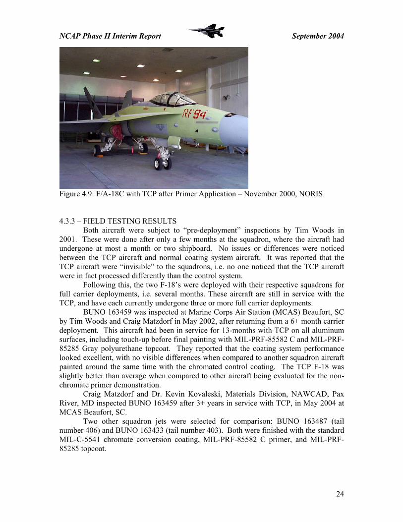
Figure 4.9: F/A-18C with TCP after Primer Application – November 2000, NORIS 4.3.3 – FIELD TESTING RESULTS Both aircraft were subject to “pre-deployment” inspections by Tim Woods in 2001. These were done after only a few months at the squadron, where the aircraft had undergone at most a month or two shipboard. No issues or differences were noticed between the TCP aircraft and normal coating system aircraft. It was reported that the TCP aircraft were “invisible” to the squadrons, i.e. no one noticed that the TCP aircraft were in fact processed differently than the control system. Following this, the two F-18’s were deployed with their respective squadrons for full carrier deployments, i.e. several months. These aircraft are still in service with the TCP, and have each currently undergone three or more full carrier deployments. BUNO 163459 was inspected at Marine Corps Air Station (MCAS) Beaufort, SC by Tim Woods and Craig Matzdorf in May 2002, after returning from a 6+ month carrier deployment. This aircraft had been in service for 13-months with TCP on all aluminum surfaces, including touch-up before final painting with MIL-PRF-85582 C and MIL-PRF-85285 Gray polyurethane topcoat. They reported that the coating system performance looked excellent, with no visible differences when compared to another squadron aircraft painted around the same time with the chromated control coating. The TCP F-18 was slightly better than average when compared to other aircraft being evaluated for the non-chromate primer demonstration. Craig Matzdorf and Dr. Kevin Kovaleski, Materials Division, NAWCAD, Pax River, MD inspected BUNO 163459 after 3+ years in service with TCP, in May 2004 at MCAS Beaufort, SC.
Two other squadron jets were selected for comparison: BUNO 163487 (tail number 406) and BUNO 163433 (tail number 403). Both were finished with the standard MIL-C-5541 chromate conversion coating, MIL-PRF-85582 C primer, and MIL-PRF-85285 topcoat.
24

NCAP Phase II Interim Report September 2004
Figure 4.10: Chromate and TCP F/A-18 C’s – May 2004, MCAS Beaufort Maintenance personnel noted that 163459 was “one of the best jets with respect to corrosion”. When asked about time or effort spent when repairing test aircraft, personnel did not feel they were paying any more or less attention to these aircraft than to others in the squadron.
TCP aircraft, while repainted for “squadron morale” and not deficiencies, exhibited excellent corrosion protection and held up quite well around fasteners. Repaint occurred over scuff-sanded finish system and did not result in the removal of the pretreatment. BUNO 163757 was inspected at NAS Lemoore, CA by Tim Woods in May 2004, after three or more full length carrier deployments. He reports that VFA-146 does an excellent job of inspecting and maintaining their planes.
The inspection showed the aircraft to be in great shape; with the overall condition with respect to corrosion being very good. The average paint thickness on this test aircraft was 5-mils, with nothing over 9-mils DFT. The squadron did not report any issues or concerns with the TCP aircraft; noting, “other jets require more diligence in maintaining the coating system.”
Figure 4.11: BUNO 163757 F/A-18C w/ TCP – NAS Lemoore, May 2004
25

NCAP Phase II Interim Report September 2004
4.3.4 – STATUS Overall, the TCP technology is performing at least as well as the standard
chromate conversion coating in this demonstration. These aircraft had at least three carrier deployments and may have had a fourth. Maintenance personnel were enthusiastic about new technologies due to their environmental and health benefits. The TCP aircraft are performing on par with the best corrosion performance of the fully chromated system. The Planned Maintenance Interval (PMI) cycle for the F/A-18 is 60-months, meaning that these aircraft will be returning to the depot for re-work in approximately two years. This will mean the TCP aircraft will have been in service for 5 years or more.
As a result of these positive field test results, and combined with the H-46 demonstrations that are discussed in Section 4.4, NAVAIR Materials is planning to authorize the use of TCP under chromated primers, with the approval letter planned to issue by the end of 2004. FY05 efforts will focus on an extensive evaluation of new, non-chromate primer systems recently qualified to MIL-PRF-23377 Class N; with field testing over TCP planned if applicable based on laboratory testing.
26

NCAP Phase II Interim Report September 2004
4.4 – NAVAIR CH-46
4.4.1 – BACKGROUND NAVAIR’s fleet of H-46 helicopters undergo depot-level rework at NADEP
Cherry Point, NC. Due to severe environmental restrictions placed on the conventional spray-on/rinse-off chemical processing methods, NADEP CP, for the past several years, has utilized a hand application wipe-on/wipe-off method for chromate conversion coating their aircraft. This procedure is used for all pre-paint surface preparation of aluminum skins for the H-46 program. The hand application method generates very little waste, thereby significantly minimizing environmental wastewater issues experienced in spray operations with hexavalent chromium.
In 2000, the Environmental Affairs Office in Cherry Point determined that the NAVAIR TCP process does not fall under the environmental and health and safety regulations that govern the hexavalent chromium processes. This is due to trivalent chromium being non-carcinogenic, unlike hexavalent chromium.
Cherry Point decided to field test the TCP on the H-46 platform, on the basis of being able to spray apply TCP. A conventional spray application conversion coating process allows for faster turn around time for aircraft undergoing Standard Depot Level Maintenance (SDLM). The current hand application method requires between 4 and 6 man-hours of labor to conversion coat one CH-46 airframe. A spray application could reduce this process time by half, which affords a significant cost savings. At FY00 labor rates, it was estimated that annual costs savings by switching to a non-hazardous spray application would be approximately $30K for the sixty aircraft processed annually on average.
4.4.2 – PROCESSING
On October 23, 2000, NADEP Cherry Point completed its first trivalent chromium conversion coating (TCP) demonstration on specific areas of an H-46 helicopter, BUNO 165454. This helicopter was scheduled to go to HMM 774 in Norfolk, VA in November, 2000.
The three areas treated were the drive shaft tunnel, forward pylon, and aft pylon and cargo door.
Figure 4.12: H-46 Components with TCP – NADEP CP, October 2000
27

NCAP Phase II Interim Report September 2004
Following a thorough cleaning, the bare metal surfaces were deoxidized using MIL-C-10578 phosphoric acid. While the surface was still wet, a total of fifteen gallons of TCP was applied using a reciprocating drum pump. Artisans sprayed the material through a fan shaped nozzle, evenly spraying the drive shaft tunnel, forward and aft pylons, and the cargo door with one coat of TCP. The TCP remained on the surface for one minute, and then a second application was sprayed onto all surfaces again. After another minute this process was repeated for a third and final time. A very faint green tint began to show following the second application. After approximately 7 minutes the aircraft was rinsed thoroughly, evaluated for any remaining residue, and rinsed once again. The pretreatment was allowed to cure overnight, and the aircraft was painted the next morning. On October 26, 2001, BUNO 154819 CH-46E was spray processed with TCP at NADEP Cherry Point. The aircraft was nearing completion of SDLM. The surface skin of the H-46 is primarily composed of clad AA2024-T3. James Whitfield, AIR 4.3.4.6 Materials, NADEP Cherry Point, NC oversaw the processing with TCP. His observations and comments on the processing are included below. The exterior surfaces of the aircraft were stripped of old paint coatings by plastic media blasting. Landing gear and other surfaces sensitive to chemical processing were masked off prior to the start of spray operations. Cleaning was accomplished using a combination of steam cleaning and by scrubbing with MIL-PRF-85570 Type II Aircraft Cleaning Compound at 20% by volume. After cleaning, the aircraft was thoroughly rinsed with clean tap water. The cleaning step required approximately 2 hours. While still wet from cleaning, the helicopter was deoxidized using MIL-C-10578 Type II Metal Cleaner and Conditioner at 20% by volume. The deoxidizer was allowed to dwell on the surface for 5-minutes before thorough rinsing with clean tap water. Surfaces were visually inspected to ensure a water-break free surface was obtained. The deoxidizing step took approximately 15 minutes and required 25 gallons of solution. While still wet, surfaces were coated using TCP solution. The TCP was spray applied from the bottom working upward to ensure complete coverage. TCP was re-applied after 5-minutes to prevent drying. Total TCP dwell time was 10 minutes. Surfaces where then thoroughly rinsed with clean tap water and allowed to dry. Ambient temperature during application was 65 0F with 50% RH. The TCP application step took approximately 15 minutes and required 35 gallons of TCP. Shop artisans indicated that the process went well and was less labor intensive than the hand application coating process used for the chromate conversion coatings. The entire cleaning, deoxidizing, and conversion coating pretreatment process took approximately 2.5 hours. They estimated that as much as 1 hour was saved on process throughput. After a 12-hour pretreatment dry time, the helicopter was primed and painted with MIL-PRF-85582 C1 water-reducible, epoxy primer and MIL-PRF-85285 TyI polyurethane topcoat. The shop artisans did note that the surface treatment color change is one of the few downsides to TCP. Conventional chromate conversion coatings provide a distinct color change on treated surfaces. TCP, however, does not provide a noticeable color change. For process consistency and quality control, a color change or other simple
28

NCAP Phase II Interim Report September 2004
means of determining surface treatment is desired. For tracking and follow-up purposes, an aircraft logbook entry was made indicating TCP surface treatment. 4.4.3 – FIELD TESTING RESULTS BUNO 154819 was fielded with HMM-264 squadron at MCAS New River, NC following final paint at Cherry Point. This aircraft was inspected by James Whitfield, NADEP CP, at HMM-264 on November 6, 2003, after 13-months in service. This aircraft had recently returned from an 8-month deployment, most of which was shipboard on the USS Iwo Jima. This deployment included tours in Iraq, the horn of Africa, Albania, and Liberia. While deployed, aircraft in this squadron were subjected to the harsh corrosive environment typical for Navy and Marine operations. The aircraft was examined to assess corrosion and coating system issues, and to compare finish system performance with other aircraft in the squadron (standard chromated coating system). Particular attention was given to fastener patterns, lap joints, butt joints, and other corrosion prone areas. The paint system was found to be in good condition with only minor touch-up indications typical of aircraft in service for 2-years. No corrosion was noted during the inspection. Squadron maintenance records indicated that there were no notable differences between corrosion or paint repairs on this aircraft and other aircraft in the squadron that were finished with standard pretreatment materials. This was confirmed by inspection of other squadron aircraft that were refinished within a few months, before or after, of the date this aircraft was painted. 4.4.4 – STATUS
The inspection results for the CH-46’s indicate that TCP is performing at least as well as standard pretreatment materials for aluminum alloys. NADEP Cherry Point has expressed the intention to implement spray processing of TCP upon issuance of the NAVAIR approval letter.
As a result of these positive field results, and combined with the F/A-18C demonstrations discussed in Section 4.3, NAVAIR Materials is planning to authorize the use of TCP under chromated primers, with the approval letter planned to issue by the end of 2004. FY05 efforts will focus on an extensive evaluation of new, non-chromate primer systems recently qualified to MIL-PRF-23377 Class N; with field testing over TCP planned if applicable based on laboratory testing.
29

NCAP Phase II Interim Report September 2004
4.5 – NASA SOLID ROCKET BOOSTERS 4.5.1 – BACKGROUND
The Space Shuttle Solid Rocket Booster (SRB) had only one set of coatings and one type of pretreatment qualified for protection of aluminum hardware. All of the materials contained chromate compounds. A project was conducted to identify and qualify alternatives for the currently qualified coating system and pretreatment.
The coatings were evaluated for corrosion protection, bond strength, compatibility with other SRB materials, batch-to-batch consistency, and thermal environments stability. Two pretreatments and two coating systems met the SRB program criteria. The recommended products are Henkel Alodine 5700, MacDermid Chemidize 727 ND, and the coating systems submitted by Hentzen and by Lord Coatings. The coating systems were tested in both a primer only and a primer/topcoat configuration. Both were found to be acceptable for flight. There are significant processing advantages for each of the materials depending on how they are used. The Hentzen coatings are chromate free and have very good processing characteristics along with good overall properties and are recommended for first implementation as an alternate. Likewise, Alodine 5700 had very robust processing parameters and is recommended for first implementation as a pretreatment alternate.
4.5.2 – FIELD TESTING
NASA began treating SRB’s with the non-chromate Alodine 5700/Hentzen primer system in 2002. The first hardware flew in the fall of 2002. 4.5.3 – STATUS
NASA implemented the Hentzen / Alodine 5700 system in June 2002. This change affected all structural aluminum (AA2219, AA6061, and AA7075) parts of the solid rocket boosters. No issues have been reported with this system.
30

NCAP Phase II Interim Report September 2004
31
4.6 – BOEING/AIR FORCE/NAVY 4.6.1 – BACKGROUND
The US Air Force and Boeing have been evaluating a Sol-gel-based conversion coating process for paint adhesion applications where chromate pretreatments are traditionally used. The surface treatment system being used is AC-131 from Advanced Chemistry and Technology in Garden Grove, CA. AC-131 is based on technology developed at Boeing as “Boe-gel” sol-gel chemistry-based conversion coating. AC-131 is intended for use as an adhesion promoter for pre-paint applications on a variety of metallic substrates.
The objective of the Advanced Aircraft Corrosion Protection (AACP) program, sponsored by the Aging Aircraft Division of the Aeronautical Enterprise Program Office, is to demonstrate and validate a coating system evolved from the AC-131/Boegel and to apply the coating system to aircraft for operational flight testing. This effort was begun in September 2002.
The project focused on two main evaluations to determine validity for field demonstration. The first significant milestone of the project was to investigate ways to make Boegel/AC-131 visibly inspectable. Several colored dyes were successfully added to the conversion coating promoting color definition. The second milestone was to validate the adhesion promoting characteristics of AC-131 on a variety of aluminum substrates and surface conditions. To accomplish this goal, the team worked to define the cleaning and deoxidizing requirements for aluminum surfaces required for good adhesion. Good adhesion was exhibited to aluminum alloys when either AC-131 or Alodine 1200S was applied, however, wet adhesion failures were observed when no conversion coating was applied. Similar adhesion performance was observed for both the AC-131 and the Alodine 1200S chromate control in wet tape and pull-off adhesion testing. The performance of coating systems with AC-131/Boegel in laboratory testing has been reported to be equivalent or sometimes better than the performance of coating systems with conventional chromate conversion coatings. 4.6.2 – STATUS
Advanced Chemistry and Technology, Inc. is currently evaluating a blue-dyed version of the AC-131 developed during the Boeing efforts to determine the adhesion performance of the colored coatings and to evaluate the effect of the dye on long term coating system performance.
The AF/Boeing plan is to field test the AC-131 versus a chromate conversion coating for prepaint operations beginning in the fall of 2004. An F-15, to be stationed at Eglin AFB, FL, and a KC-135 support aircraft, to be stationed at Hickam AFB, HI, will be painted at Warner Robbins ALC and The Boeing Aircraft Support Center (BASC), respectively, both in San Antonio, TX. Half of each aircraft will receive the conventional chromated coating, with the other half being processed with the AC-131 non-chromate sol-gel coating. The aircraft will then be primed with MIL-PRF-23377 C chromated, epoxy primer and top-coated with Advanced Performance Topcoat (APC). This effort is planned for the November 2004 timeframe.

NCAP Phase II Interim Report September 2004
5.0 – ESTCP NCAP EFFORTS 5.1 – US NAVY LANDING CRAFT, AIR CUSHIONED 5.1.1 – BACKGROUND The current pre-paint procedure for the Landing Craft, Air Cushioned (LCAC) amphibious vehicle hulls, which are composed primarily of AA5456-H116, involves abrasive blasting with garnet until a surface profile of 3 mils is achieved. Selected compartments and voids are then coated with a solvent-reducible, non-chromated epoxy primer, MIL-DTL-24441B Type III, Formula 150, to a dry film thickness (DFT) of 3-4 mils and then coated with MIL-DTL-24441B Type III, Formula 151 for a final DFT of 6-8 mils. This is done for the recently created Craft Alterations CA-369K and CA-445K, which apply coatings to selected corrosion prone voids. Hexavalent chromium chemistry was suspended by NAVSEA in August 1991 and an alternative to abrasive blasting for surface preparation is desired. Several issues have arisen with the current direct-to-metal process, one of which is adhesion loss due to undercutting and undercutting exacerbated by crevice corrosion between substrate and coating, and another being coating cracking due to craft flex and vibration. Surface preparation is a key concern, as MIL-DTL-24441B exhibits poor adhesion when the nominal surface profile is less then 3-mils. This can be achieved by grit-blasting, but not by other mechanical surface preparation methods, such as shot-peening or grit-impregnated sanders. AA5456-H116 has a tendency to polish after approximately 2 mils of profile have been achieved by mechanical methods. Additionally, both Assault Craft Unit Four (ACU-4) and ACU-5 prohibit sailors from abrasive blasting due to dust generation. This adversely affects the coatings performance of any maintenance and repair efforts conducted at the unit level. With respect to CRAFTALT installation as performed by contractors, production schedule analysis has indicated that implementation of TCP in place of the current abrasive blast process could reduce production time by 23 man-days and hangar time by 8 days. These tests were initiated and overseen by Mr. Paul Dobias, NSWC Carderock Division, Materials Process and Engineering Branch. The LCAC program began testing TCP as a potential surface preparation method, allowing a substitution for abrasive blasting as a pre-paint process. The TCP was chosen for demonstration because of the potential for realizing both a time/cost savings, as well as improved adhesion and corrosion performance when compared to a direct-to-metal process. 5.1.2 – FIELD TESTING
The US Navy LCAC program has been field-testing TCP for the last 3-4 years, in both beach-side outdoor exposure testing and vehicle applications. This work was conducted at ACU-4 in Little Creek, VA. The LCAC is a NAVSEA program, and initiated this field test using ARCOVA-supplied TCP. The exposure testing was conducted on panels composed from AA5083-H111, AA5086-H116, and AA5456-H116 (AA5456-H116 is the primary alloy used for construction of LCAC hull structures). Al alloy Surface Prep Primer Test 5456H116 5086H116 5083H111
None, Garnet-blast to 3 mil, 120-grit abrade w/ TCP
None Bare, Beachside Outdoor Exposure
5456H116 5086H116 5083H111
None, Garnet-blast to 3 mil, 120-grit abrade w/ TCP
MIL-DTL-24441B TyIII F150/151 DFT – 8-10 mil
Scribed, Painted Beachside Outdoor Exposure
32

NCAP Phase II Interim Report September 2004
Table 5.1: Beach-side Exposure Testing – begun March 2001, ACU-4 Little Creek, VA
Two test components were treated on LCAC-26 in August 2000, to examine the TCP as an adhesion promoter for surface preparation, and to evaluate TCP for surface corrosion protection. The components were painted with MIL-DTL-24441B TyIII. The first test area was the deck of the oily waste tank, which can contain MIL-H-23699 hydraulic fluid, seawater, and engine cleaning detergents. This is an area where adhesion loss is observed due to breakdown of the organic coating. Figure 5.1: LCAC-26 Oily Waste Tank with TCP Test Patch
The second test area was on the deck where there is a void observed to suffer periodic seawater penetration. The TCP for this effort was obtained from the American Research Corporation of Virginia (ARCOVA). 5.1.3 – RESULTS Beach-side testing coupons were exposed on 30 degree racks at the Little Creek, VA site for the last 4 years. Within 6 months of exposure, the scribed painted coupons with no surface preparation exhibited undercutting from the scribe. The garnet-blasted coupons developed undercutting around 3.5 years, the TCP coupons are still in testing, no undercutting is evident. Figure 5.2: Beach-side Exposure Racks, Little Creek, VA
33

NCAP Phase II Interim Report September 2004
Untreated Blasted TCP Figure 5.3: AA5456-H116 Coupons (Bare, Blasted, or TCP) coated with MIL-DTL-24441B F150/151 – 1.5+ years Beach-side Exposure In December 2002, the test coupons were evaluated for surface pitting and general corrosion. Both the garnet blasted coupons and the coupons treated with TCP performed better than those with no surface preparation, which were now bare due to all of the coating having lost adhesion. The overall evaluation was that TCP reduced the incidence of pitting corrosion comparative to other surface preparation methods. The two painted TCP components were evaluated after 4 years of service on LCAC #26; where no corrosion, undercutting, or adhesion failures were noted. This demonstrated the adhesion performance when subjected to both corrosive and vibrational/flexing environments. The field test for bare corrosion resistance was deemed inconclusive due to prior pitting damage that was not fully removed. Figure 5.4: TCP Applied to Air Intake Plenum Deck, LCAC-26 5.1.4 – STATUS NAVSEA PEO SHIPS, PMS 377 has indicated that they will authorize TCP for pretreatment of aluminum alloys of LCAC as soon as commercial products are qualified to MIL-DTL-81706B and concurrence from the Technical Warrant Holder (TWH) are obtained.
34

NCAP Phase II Interim Report September 2004
5.2 – USMC EXPEDITIONARY FIGHTING VEHICLE 5.2.1 – BACKGROUND
The Marine Corps’ current Amphibious Assault capability currently relies on the use of the legacy platform USMC Amphibious Assault Vehicle (AAV); a lightly armored aluminum troop carrier capable of transporting a full squad of Marines from an off-shore transport ship onto dry land. This platform is from a 20+ old design, and the USMC realized the need to update their capability in this critical area. The Expeditionary Fighting Vehicle (EFV) program was originally designated the AAAV – Armored Amphibious Assault Vehicle. The contractor and designer, GDAMS, has been manufacturing and testing prototype and SDD vehicles for the past few years. The SDD phase is still underway, with all ten of the planned vehicles either in testing or in the final stages of manufacture; with the planned production of one more training vehicle. For reasons of weight limit concerns, and because of improved ballistics properties; the EFV program decided to move away from the AA5083-H131 alloy used for the AAV, and chose a new alloy AA2519-T87. While the ballistics and strength/weight ratio improved with the use of this alloy, the problem of corrosion was greatly magnified. AA2519 is a high copper alloy very susceptible to pitting and exfoliation corrosion. Due to the use of a corrosion-prone alloy, in conjunction with the extremely harsh operating environment experienced by the EFV; the corrosion control coatings and materials must be as robust at possible. At the outset of this new acquisition program, the PM made the executive decision to comply with the strictures of an environmentally “green” program. Included in this is the full prohibition of the use of hexavalent chromium containing coatings. The OEM is GDLS; and the EFV’s are being produced at the Lima Army Tank Plant (LATP) facility, in Lima, OH. The LATP site is where the US Army’s M1A2 Abrams battle tank is manufactured. Originally, the EFV prototype vehicles were prepared and coated using a grit-blast/wash primer process that had shown good performance characteristics on high-strength and armor steel alloys (like the Abrams). During initial field and in-water testing with P1, the first prototype vehicle, serious problems arose with the coating system and its corrosion performance. These corrosion and adhesion issues needed to be addressed for the unique performance and operational requirements of AA2519-T87. The corrosion coating system issues that needed to be addressed were serious coating/substrate adhesion loss on the P1 hull, turret, and other components, as well as rapid exfoliation corrosion of the aluminum substrate. The initial coating procedure was wash with a standard alkaline steel cleaner, abrasive blast with alumina to a 1.5-2.0 mil surface profile, wash prime with a water-reducible non-chrome primer, prime with a solvent-reducible, epoxy CARC, and finally topcoat with a water-reducible, polyurethane CARC. It was suggested that the program look into a chemical process and conversion coat surface preparation in lieu of the mechanical surface preparation/wash primer process. 5.2.2 – P1 - TCP PERFORMANCE VALIDATION General Dynamics and the EFV Program requested that the Inorganic Coatings Team (ICT) refurbish deflectors, part number AV1060625, commonly called “steering buckets” and two seal plates, numbers AV106015-1P (port side) and AV106015-1A (starboard side) from EFV P1.
35

NCAP Phase II Interim Report September 2004
Two deflectors were refurbished and an evaluation was done to validate the performance of NAVAIR’s TCP using a standard “wet” surface preparation process. These parts were grit blasted with alumina on August 14, 2001 to remove the paint system and corrosion products. Later that morning the four components were processed in the Inorganic Coatings Lab, Patuxent River, MD using the following process:
1. Cleaned using a warm mildly-alkaline, non-silicated, non-etching aluminum cleaner. (Turco 4215 NC LTTM – 120 F) Solution was scrubbed lightly onto the components with Scotch-Brite pads. Figure 5.5 shows the cleaning of a steering bucket.
2. Rinsed thoroughly with warm tap water followed by deionized (DI) water. 3. While still wet, Turco 3003 TWA cleaner/deoxidizer was hand-applied with Scotch-Brite
pads, scrubbing gently to ensure contact of the chemical with all surfaces. 4. Allowed 3003 TWA to dwell on the substrate for 15 minutes. 5. Rinsed thoroughly with cold tap water followed by DI water. 6. While still wet, spray-applied TCP10P solution using a two-liter, hand-pumped solution
sprayer. Figure 5.6 shows the application of TCP. 7. Allowed TCP to dwell on the surface for 5 minutes, keeping the surface wet. This
required the additional misting of the surface twice due to the low humidity and high airflow in the lab.
8. Rinsed thoroughly with cold tap water followed by DI water. 9. Allowed components to air-dry for one hour. Figure 5.7 shows a component with a dried
TCP film.
Figure 5.5: Cleaning Steering Bucket
36

NCAP Phase II Interim Report September 2004
Figure 5.6: Application of TCP
Figure 5.7: TCP Coating after Drying
37

NCAP Phase II Interim Report September 2004
Later in the afternoon of August 14, 2001, the components were painted using MIL-PRF-85582-NC Type II primer from PRC-DeSoto in the Organic Coatings Paint Lab in Building 2188. This primer is flat black in color. On the morning of August 15, 2001, the components were painted with a MIL-C-53039 gray CARC topcoat from Hentzen. Components were allowed to cure until late in the afternoon when they were picked up by a member of the GDAMS team and taken back to the test building. It is important to note that the tight schedule for reworking the components led to only a 6-hour cure for the topcoat. Ideally, the topcoat would be allowed to cure for 24 hours before handling and exposure to a corrosive environment. Painted components are detailed in Figures 5.8, 5.9, and 5.10. All four components were reinstalled on the P1 that evening and painted black for aesthetic purposes.
Figure 5.8: Steering Bucket after Priming with MIL-PRF-85582 NC
Figure 5.9: Steering Bucket after Topcoat Application with MIL-C-53039
38

NCAP Phase II Interim Report September 2004
Figure 5.10: Seal Plate after Topcoat Application with MIL-C-53039 While the components were being painted on the afternoon of August 14, members of the Inorganic Coatings Team (ICT) applied a TCP coating to the mating surfaces of the seal plates on the port and starboard sides where corrosion and adhesion damage had occurred. In addition, the P1 team requested that TCP coating be applied to the port and starboard water jet thrust plates. These areas were cleaned and mechanically prepped by the P1 team. Immediately after being wiped clean with an alcohol wipe, the surfaces were treated with TCP. The TCP was wiped onto the surfaces using a clean cotton rag and allowed to dwell for 10 minutes. Repeat applications of TCP were made after approximately three to seven minutes. No TCP solution ran onto adjoining surfaces. After the dwell, un-reacted solution was wiped from the treated surfaces using a second clean rag saturated with clean DI water. The surfaces were then allowed to air-dry with help from a large fan. That evening, the P1 crew primed these surfaces using MIL-PRF-85582 NC material applied from Sem-penTM touch-up paint applicators. Figures 5.11 and 5.12 depict the TCP touch-up process.
39

NCAP Phase II Interim Report September 2004
Figure 5.10: Seal Plate Mating Surface after Corrosion Removal
Figure 5.11: Application of TCP Coating on Seal Plate Mating Surface 5.2.3 – LABORATORY TESTING Concurrently with the limited initial field testing on the P1, a large laboratory panel test matrix was started at PAX to determine the optimum surface preparation and pre-paint coating system for processing of later prototype and SDD vehicles at LATP. This matrix looked at the possible process combinations resulting from using grit-blasted and as-machined surfaces, with and without an alkaline chemical cleaner, and with and without a chemical deoxidation step. Two wash primers at specified thicknesses were evaluated by dry/wet tape adhesion and neutral salt fog (ASTM B117) compared to two non-chromate chemical conversion coating alternatives and a chromate control. All coating permutations were subsequently coated with either MIL-PRF-85582 N or MIL-P-53022, with MIL-PRF-85582C1 as the chromated control primer. 40

NCAP Phase II Interim Report September 2004
Mechanical Surface Prep
Dwell Alkaline Clean Chemical Deoxidize
Pretreatment or Wash Primer Primer Test
Grit Blast 2 hours or 24 hours
None, Turco 4215, or MEK solvent wipe
none or Turco 3003/SmutGo
Aqua Zen (1.0, 2.5, & 4.0 mils)
85582 NC or 53022
Dry, 1,4,7 Day Wet Adhesion or ASTM B117 NSF
Grit Blast 2 hours or 24 hours
None, Turco 4215, or MEK solvent wipe
none or Turco 3003/SmutGo
Kem Aqua (1.0, 2.5, & 4.0 mils)
85582 NC or 53022
Dry, 1,4,7 Day Wet Adhesion or ASTM B117 NSF
Grit Blast 2 hours or 24 hours
None, Turco 4215, or MEK solvent wipe
none or Turco 3003/SmutGo
Slikote (1.0, 2.5, & 4.0 mils)
85582 NC or 53022
Dry, 1,4,7 Day Wet Adhesion or ASTM B117 NSF
As-Machined N/A None, Turco 4215, or MEK solvent wipe
none or Turco 3003/SmutGo
Aqua Zen (1.0, 2.5, & 4.0 mils)
85582 NC or 53022
Dry, 1,4,7 Day Wet Adhesion or ASTM B117 NSF
As-Machined N/A None, Turco 4215, or MEK solvent wipe
none or Turco 3003/SmutGo
Kem Aqua (1.0, 2.5, & 4.0 mils)
85582 NC or 53022
Dry, 1,4,7 Day Wet Adhesion or ASTM B117 NSF
As-Machined N/A None, Turco 4215, or MEK solvent wipe
none or Turco 3003/SmutGo
Slikote (1.0, 2.5, & 4.0 mils)
85582 NC or 53022
Dry, 1,4,7 Day Wet Adhesion or ASTM B117 NSF
Grit Blast 2 hours or 24 hours
None, Turco 4215, or MEK solvent wipe
none or Turco 3003/SmutGo Alodine 5200 85582 NC
or 53022
Dry, 1,4,7 Day Wet Adhesion or ASTM B117 NSF
As-Machined N/A None, Turco 4215, or MEK solvent wipe
none or Turco 3003/SmutGo Alodine 5200 85582 NC
or 53022
Dry, 1,4,7 Day Wet Adhesion or ASTM B117 NSF
Grit Blast 2 hours or 24 hours
None, Turco 4215, or MEK solvent wipe
none or Turco 3003/SmutGo TCP 85582 NC
or 53022
Dry, 1,4,7 Day Wet Adhesion or ASTM B117 NSF
As-Machined N/A None, Turco 4215, or MEK solvent wipe
none or Turco 3003/SmutGo TCP 85582 NC
or 53022
Dry, 1,4,7 Day Wet Adhesion or ASTM B117 NSF
Grit Blast 2 hours or 24 hours
None, Turco 4215, or MEK solvent wipe
none or Turco 3003/SmutGo
Turco Accelagold (chromate control)
85582 NC or 53022
Dry, 1,4,7 Day Wet Adhesion or ASTM B117 NSF
As-Machined N/A None, Turco 4215, or MEK solvent wipe
none or Turco 3003/SmutGo
Turco Accelagold (chromate control)
85582 NC or 53022
Dry, 1,4,7 Day Wet Adhesion or ASTM B117 NSF
Grit Blast N/A Turco 4215 Turco 3003/SmutGo
Accelagold, TCP, Alodine 5200
85582 C1 Dry, 1,4,7 Day Wet Adhesion or ASTM B117 NSF
Table 5.2: Coating System Test Variables
41

NCAP Phase II Interim Report September 2004
The last coating system variable was the control, a fully chromated coating system – using a chromate control primer, MIL-PRF-85582C1 evaluated over the chromate control, as well as a chromated primer control over non-chromate pretreatments Alodine 5200 and TCP. The process protocols are outlined below. 1. Alkaline Cleaner – Turco 4215 NC LT, 15-minute immersion at 120 0F 2. Deoxidizer – Turco 3003 TWA 25% by volume, 15-minute contact by spray application at ambient temperature with a Scotch-Brite scrub 3. Desmutter – Turco Smut-Go NC, 30 to 60-second contact by spray application at ambient temperature 4. Primer – Mil-PRF-85582 C and N & Mil-P-53022 were applied at a DFT of 0.9-1.5 mils 5. Topcoat – MIL-DTL-64159 Type II CARC 383 Green for ASTM B117 Neutral Salt Fog 6. Process – Coupons were rinsed thoroughly between each step with ambient DI water 7. Coupons were not allowed to dry out between process steps. This mitigates re-oxidation or contamination of the surface 8. Pretreated surfaces were allowed to dry overnight before primer applications or per technical process instruction for the wash primer products 9. Coupons were top-coated 24 to 48-hours after primer application 10. Grit-Blast with alumina (aluminum oxide) to a 1.0-1.5-mil surface profile 11. Wash Primers were applied at wet film thicknesses of 1.0, 2.5, and 4.0-mils – corresponds to a DFT of 1.0, 1.5, and 2.0-mils 5.2.4 – P1 AND LABORATORY TESTING RESULTS 5.2.4.1 – LABORATORY TESTING The chemical conversion coatings, Alodine 1200S, TCP, and Alodine 5700 outperformed the wash primers in corrosion and adhesion testing, regardless of primer. Both of the non-chromate conversion coatings averaged better than a “4A” rating in dry and wet adhesion testing by ASTM D 3359, regardless of surface preparation method or subsequent primer coating. Based on the delamination and blistering issues noticed with the wash primer coating system on the P1, NAVAIR made the recommendation that for this aluminum alloy and operational environment, the EFV program should use a chemical conversion coating as the preferred surface preparation process. In the laboratory testing, no difference was observed in the corrosion and adhesion performance of the conversion coatings when applied over an as-machined surface compared to a grit-blasted surface. The EFV program decided to pursue a chemical clean and deoxidation process, which is less costly and less time/labor intensive than an abrasive blast process. The performance of the wet processed TCP/MIL-PRF-85582 NC coating system merited additional investigation and validation of the process and coating system for potential implementation by GD for the EFV program. Early performance feedback led to discussions of potentially using a wet process for new hulls as well as evaluating TCP in other EFV applications including the track cover door, sprocket carriers, idler wheels and hull touch-up. 5.2.4.2 – PERFORMANCE OF INITIAL COMPONENTS WITH TCP ON EFV P1 NAVAIR personnel visually inspected the performance of the new coatings after one, two, four and six week intervals. Feedback was also garnered from the P1 crew. At each interval there was no evidence of corrosion, paint blistering or other coating problems. Figures 5.13 and 5.14 show the starboard steering bucket and seal plate on EFV P1 after 2 weeks in service on the platform. The performance of the pretreated components on the P1 was
42
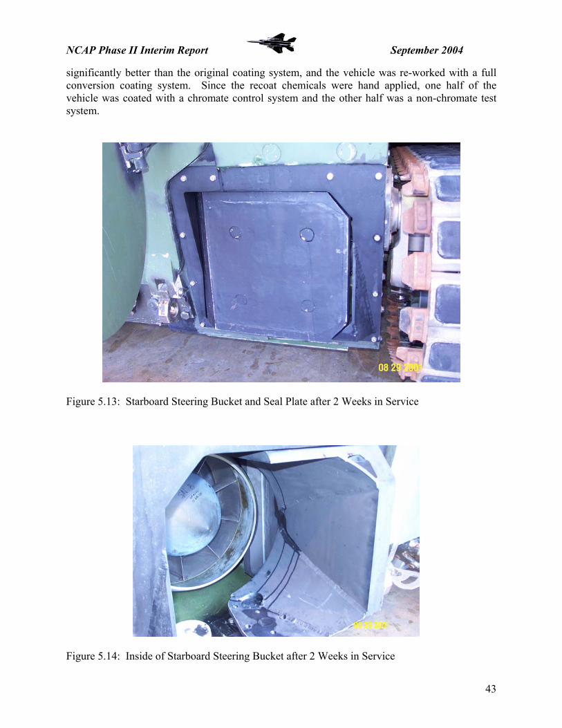
NCAP Phase II Interim Report September 2004
significantly better than the original coating system, and the vehicle was re-worked with a full conversion coating system. Since the recoat chemicals were hand applied, one half of the vehicle was coated with a chromate control system and the other half was a non-chromate test system.
Figure 5.13: Starboard Steering Bucket and Seal Plate after 2 Weeks in Service
Figure 5.14: Inside of Starboard Steering Bucket after 2 Weeks in Service
43

NCAP Phase II Interim Report September 2004
5.2.5 – SDD VEHICLE HULL AND TURRET PROCESSING 5.2.5.1 – BACKGROUND
The SDD phase of this new acquisition program began in 2000, with the production and processing of E1 at LATP. Ten vehicles were planned for the SDD phase, nine “E” variants – standard model squad amphibious vehicle, and 1 “C” variant – a commander’s vehicle, lacking the 25mm gun on the turret but with an upgraded communications and electronics package. Based on the outcome of the early laboratory testing and the initial field test data on the P1 components, Alodine 5700 and TCP were selected as the non-chromate conversion coating alternatives. One SDD vehicle was planned for a fully chromated coating system. 5.2.5.2 – INITIAL PROCESSING Craig Matzdorf from NAVAIR was present at LATP for the processing of the first SDD EFV – E1. GDAMS and Henkel Surface Technologies (HSTNA) – maker of the AlodineTM product line and main chemical supplier for LATP – were also present for on-site technical support. The E1 process used an alkaline cleaner already stocked at LATP for cleaning of painted steel surfaces, and an aerospace standard phosphoric acid deoxidizer with a mild, nitric-acid desmutter for surface preparation. The E1 vehicle was sprayed with Alodine 5700 using 2-gallon plastic garden sprayers. Several spray processing recommendations were made by NAVAIR and HSTNA, and these changes were incorporated into the process for the next vehicle. 5.2.5.3 – PROCESSING
When initial prototype and SDD manufacture began for this program, LATP did not have any experience with aluminum finishing. The original prototype vehicles were mechanically prepared and wash primed with the same process as that employed for steel substrates. Additionally, the use of a newly designed aluminum alloy, AA2519-T87, meant that there was a large learning curve to overcome in the pretreatment of these vehicles. The first few vehicles in SDD exhibited cohesive adhesion failures occurring at the primer metal interface. This indicated a possible problem with the conversion coating process. The original chemical process needed improvements in chemical selection, application temperatures, and greater attention to detail in chemical dwell times and rinsing parameters. The first issue, resolved after the processing of E1, was the use of the 2-step deoxidation/de-smutting process originally suggested by NAVAIR. While this process worked well in the laboratory tests, it was found to be too time and labor intensive for a manual spray process application. By the time the chemicals were finished being applied, the first area would be dry, allowing for the deposition of chemical contaminants and/or re-oxidation of the aluminum substrate. Laboratory testing was conducted at NAVAIR to look at milder, slower acting single-step deoxidizers that would not cause extensive smutting of the surface, even at longer dwell times. RidolineTM 4450, a citric/dilute hydro-acetic acid mix was selected as the giving the best clean, oxide free surface without smutting. E2 was processed using the Ridoline 4450. The next issue was the use of the K-56TM cleaner, where it was observed that even after several cleanings, the aluminum did not exhibit a uniformly water-break free surface. A water-break free surface indicates the high-surface tension of the metal when it is free of organic contaminants such as machining oils, dirt, and fingerprints. HSTNA suggested the use of a cleaner, AerowashTM, specifically designed for cleaning aluminum alloys. The transition was
44

NCAP Phase II Interim Report September 2004
made to the use of Aerowash before E4; however, it was noted that the Aerowash’s cleaning capability was greatly diminished when not used at an elevated temperature.
Figure 5.15: EFV E3 Spray Processsing – LATP For quality control, several adhesion tests were conducted for each vehicle, in accordance with ASTM D 3359 Procedure B, to ascertain the consistency of the processing and the quality of the conversion coating. Adhesion issues were seen up to SDD vehicle E4, as the process parameters were gradually optimized. It was noted that the third SDD vehicle, C1, had the best overall adhesion (though still not in keeping with performance levels suggested by laboratory testing). This vehicle experienced the shortest dwell times and most consistent rinsing of the early demonstrations. This suggested that with proper process control and optimization, high performance could be achieved with the selected non-chromate pretreatments. Between E4 and E7, several significant changes were made to the process chemicals and controls. E6 was the chromate control vehicle, and no adhesion or processing issues were experienced. E7 was processed with the non-chromate system, TCP and MIL-P-53022. 5.2.5.4 – E7 PAINT ADHESION RESULTS There were no adhesion issues observed with E7. The processing dwell times were exactly within the optimum range and the TCP solution was diluted to 30% by volume instead of the usual 50% by volume. This may have lowered the solution activity, making the conversion coating reaction less restrictive on dwell time.
45

NCAP Phase II Interim Report September 2004
5.2.6 – PROCESSING – CURRENT PROCESS 5.2.6.1 – E8 Processing for the E-08 began on 15 March 2004. Table 5.3 outlines the pretreatment steps for the EFV E8 including alkaline cleaning, deoxidizing and application of TCP. A four-man crew was used. All adhesion test results were ratings of 4A or better.
Time Notes 0845 Rinsed pumps, hoses and vacuum tubes. Filled rinse barrel. Retrieved a degrease
can on top of the vehicle. K-56 wash only at de-burr station. Very little filings. Spray cleaned with hot Aerowash™.
0853 Begin Aerowash™. 0909 Finish Aerowash™. Good foamy coverage. 0930 Finish rinse. Stress high volume, low pressure for rinsing vehicles. 0935 Vacuum out water. Three new drain holes on this vehicle resulted in less water
being trapped after rinsing. Will do a double rinse after deoxidizing – first quick rinse to dilute the chemical and a second longer rinse to focus better on coverage and inserts.
0945 Break. 0950 Chips and shavings appear to have collected at the two rear central floor panels.
Vacuumed prior to deoxidizing. 1015 Begin deoxidization using Ridoline 4450™. Start from bottom of vehicle and work
up. 1029 Begin first rinse. 1032 Begin second rinse focusing on inserts. 1050 Vacuum out all water. 1102 Begin TCP application. Start from the bottom and work up the vehicle. Apply on
outside of vehicle, then inside of vehicle and finally a quick second coat on the outside.
1125 Begin Rinse. 1145 Final DI water rinse.
Table 5.3: Outline of E8 Processing
46

NCAP Phase II Interim Report September 2004
5.2.6.2 – E9 Time Notes
0834 Started Aerowash. Began in front, then below hull, up the sides to the top and then inside.
1005 Completed Aerowash. Total Aerowash time – 45 minutes 1010 Rinsing started. 1035 Rinsing finished. Nice water break-free surface. 1040 Excess water vacuumed out of hull from areas where it had collected. Set-up
Ridoline 4450 spray wands and pump hoses. Two 2.5 gal/min. pumps were to be used.
1048 Vacuuming complete. 1216 Began spraying Ridoline 4450. 4450 application approximately 25 minutes. 1241 Began rinse. Rinse overlapped approximately one minute more of 4450 application. 1302 Finished rinsing. Total rinse time ~ 20 minutes. 1309 Begin TCP-cc2 spray. 1331 Completed TCP-cc2 application. 1332 Began fire hose rinse. 1347 Finished fire hose rinse. 1349 Began DI water rinse. 1404 Finished DI water rinse.
Table 5.4: Outline of E9 Processing This was the first vehicle to receive a spray application of TCP-color. TCP-color is a pH-
stabilized formulation of the TCP used on the previous vehicles. TCP-color also incorporates additional chemistry that enables a color change upon the treated areas for an easier visual confirmation of the application. Previous laboratory studies showed a dark purple/brown color on treated areas when using an immersion application process. High-pressure spray application could not be suitably tested within the laboratory environment prior to use on the vehicle. After TCP-color application, a visible color change was not observed. A darker brown/gray coloring was visible in areas where TCP streaked/ran off from inserts. See Figure 5.16. This same coloring could also be seen where TCP pooled in pocketed areas of the vehicle. An overall very slight smoky appearance could be seen on the vehicle. The iridescent appearance from the non-color change TCP was more evident than the observed color change from the TCP-C application. The dark colored streaking and well areas were examined the following morning and a powdery coating was not present in those areas. Regardless of film coloration, no adhesion failures were seen with this vehicle.
47
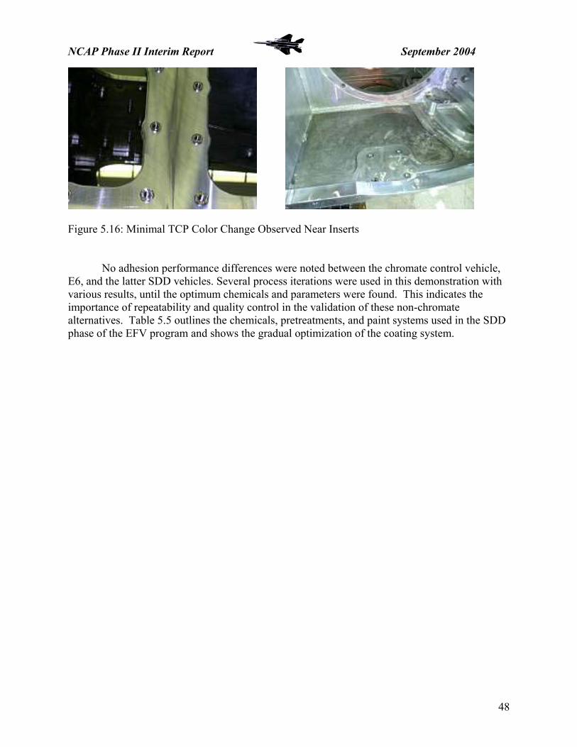
NCAP Phase II Interim Report September 2004
Figure 5.16: Minimal TCP Color Change Observed Near Inserts
No adhesion performance differences were noted between the chromate control vehicle, E6, and the latter SDD vehicles. Several process iterations were used in this demonstration with various results, until the optimum chemicals and parameters were found. This indicates the importance of repeatability and quality control in the validation of these non-chromate alternatives. Table 5.5 outlines the chemicals, pretreatments, and paint systems used in the SDD phase of the EFV program and shows the gradual optimization of the coating system.
48

NCAP Phase II Interim Report September 2004
Paint Plan as of 02/03/03
SDD Vehicle Cleaner Deox Pretreatment Primer Exterior Top Coat Interior Top Coat Build Order
E1
K-56 Turco 3000/Turco
Smut-go Alodine 5700 MIL-PRF-85582 - NC MIL-PRF- 64159 TyII
CARC MIL-PRF-22750 1
E2 K-56 Ridoline 4450 Alodine 5700 MIL-PRF-85582 - NC MIL-PRF- 64159 TyII
CARC MIL-PRF-22750 2
C1 K-56 Ridoline 4450 NAVAIR - TCP MIL-P-53022 MIL-PRF- 64159 TyII
CARC MIL-PRF-22750 3
E3 Aerowash Ridoline 4450 NAVAIR - TCP MIL-PRF-85582 - NC MIL-PRF- 64159 TyII
CARC MIL-PRF-22750 4
E4 Aerowash Ridoline 4450 Alodine 5700 MIL-P-53022 MIL-PRF- 64159 TyII
CARC MIL-PRF-22750 5
E5
Aerowash Ridoline 4450 NAVAIR - TCP MIL-P-53022 MIL-PRF- 64159 TyII
CARC MIL-PRF-22750 6
E6 Aerowash Ridoline 4450Alodine 1200S -
Hex Cr MIL-P-23377 - C MIL-PRF- 64159 TyII
CARC MIL-PRF-22750 7
E7 Aerowash Ridoline 4450 NAVAIR - TCP MIL-P-53022 MIL-PRF- 64159 TyII
CARC MIL-PRF-22750 8
E8 Aerowash Ridoline 4450 NAVAIR - TCP MIL-P-53022 MIL-PRF- 64159 TyII
CARC MIL-PRF-22750 9
E9 Aerowash Ridoline 4450 NAVAIR - TCP MIL-P-53022 MIL-PRF- 64159 TyII
CARC MIL-PRF-22750 10
Alodine 5700 and TCP are Non-hexavalent chromium conversion coatings MIL-P-53022, and MIL-PRF-85582 N are Non-hexavalent chromium primers. E6 is a fully chromated system - this is the control vehicle Table 5.5: SDD PAINT PLAN
49

NCAP Phase II Interim Report September 2004
5.2.7 – CURRENT PROCESS – LRIP The chemical process will be as finalized in the SDD phase: standard aluminum process, spray clean – 100+ 0F, mildly-alkaline, non-etching, non-silicated cleaner; spray deoxidize – ambient, non-smutting citric/acetic acid solution; spray conversion coating – ambient TCP or Alodine 5700. The current manual spray process – 3-4 man team, 6 hours start to finish is planned to be replaced in Low Rate Initial Production (LRIP) with an automated, car-wash style spray processing line for clean, prep, and conversion coating application. Alkaline Cleaner Aerowash 10% vol. 100 F Deoxidizer Ridoline 4450 10-15 minute dwell Pretreatment TCP 30-50% vol. 10-15 minute dwell Primer MIL-P-53022 CARC white Topcoat (Interior) MIL-C-22750 seafoam green Topcoat (Exterior) MIL-DTL-64159 TyII CARC 383 Green or Tan Table 5.5: Target coating system for EFV LRIP 5.2.8 – PROTOTYPE AND SDD VEHICLES FIELD TESTS 5.2.8.1 – P1 - PERFORMANCE OF CHROMATED AND NON-CHROMATED SYSTEMS ON USMC-EFV P1 P1 and P3 were stripped and repainted by a third-party, industrial painter using chemical conversion coating as the surface preparation before field testing, because of the corrosion and paint adhesion issues experienced with the prototype vehicles. Both vehicles had a fully chromated test coating on the starboard side that was compared to a non-chromated coating system, using TCP as the pretreatment, on the port side.
Before the P1 vehicle was fielded at the USMC Amphibious Vehicle Test Branch (AVTB) at Camp Pendleton, the paint system was scribed through in an “X” pattern at several locations on the hull. The main scribe location was forward on the lower side-wall of each vehicle. This area is subject to scrapes and dings during land movement, and is fully submerged when the vehicle is in the water. The initial inspection of P1 was conducted at 4 months, at AVTB. Preliminary results indicated that the non-chromate system was keeping pace with the chromated products. The next inspection was conducted at roughly 1 year of testing, in August 2003.
50

NCAP Phase II Interim Report September 2004
P1 Non-chromate vs. chromate Testing Results
Non-Chromate Chromate
Figure 5.17: P1 – 4 Months In-Water Testing 51

NCAP Phase II Interim Report September 2004
Craig Matzdorf, NAVAIR, visited the AVTB on the morning of August 6, 2003 and observed corrosion issues on the forward scribed areas on each side of the P3 hull. A field observation was conducted and photos were taken of interior and exterior examples of corrosion. The forward scribed area on each side of the hull of the USMC-EFV P1 was observed. The chromated coating showed no corrosion whatsoever, with the scribes remaining bright and shiny. The non-chromated coating showed some white corrosion product in the scribe and one or two small corrosion pits. No undercutting or damage was noted away from the scribes. The other general areas that were visible showed no difference in performance on either side. Of note is that the vehicle was parked facing north and the port side (with the non-chromate system) was very wet under the flaps. The starboard side (with the chromate system) was dry. This may be due to the washing schedule and how much sun the EFV gets after rinsing. If the port side is typically wet longer, the corrosion potential is far higher than for the starboard side. This must be taken into account when comparing the coating systems. It was suggested that AVTB personnel be questioned regarding the rinsing protocol and whether the port side does typically stay wet longer, before or after rinsing. It was noted that the steering buckets and brackets around them on both sides were different than previously and had large unpainted areas that were beginning to surface corrode and pit. It was recommended that these surfaces be cleaned of corrosion, treated with TCP, primed and top-coated as soon as possible to prevent further degradation.
Figure 5.18: P1 Inspection – C. Matzdorf at AVTB, Camp Pendleton – August 2003
52

NCAP Phase II Interim Report September 2004
P1 was inspected by Bill Nickerson of NAVAIR and Kevin Clark of GDAMS at the GDAMS Woodbridge, VA facility on February 19, 2004. Again, similar surface corrosion and paint adhesion performance was observed between the fully chromated and fully non-chromate coating systems.
One area of concern was noted in the performance difference with respect to galvanic corrosion. The non-chromate system exhibited significantly more corrosion around dissimilar metal interfaces than did the chromated coating system. It was noted that the non-chromate system was MIL-PRF-85582 N primer, a water-reducible non-chrome epoxy primer; while the chromated side was MIL-PRF-23377 C2 primer, a solvent-reducible chromated epoxy primer.
Subsequent laboratory testing confirmed that the large discrepancy in galvanic protection was a property of the primer system. The MIL-P-53022 solvent-reducible non-chrome epoxy primer performed very similarly to the MIL-23377 C2 primer; leading to the conclusion that a solvent-based primer, regardless of chromate content, was preferable for galvanic corrosion protection due to increased barrier protection against moisture ingress compared to water-based primers for use on the EFV platform. 5.2.8.2 – E2 AND E7 – IN WATER TESTING, AVTB, CAMP PENDLETON, CA EFV SDD Vehicles E2 and E7 were inspected by Bill Nickerson, NAVAIR, and Kevin Clark, GDAMS, along with Subra Bettadapur, DRPM AAA, at AVTB, Camp Pendleton on May 24, 2004. These vehicles have been undergoing in-water testing and evaluation at the Amphibious Vehicle Test Branch, Camp Pendleton, CA for almost 2 years. Both of these vehicles were spray processed at the LATP facility with a non-chromate alternative conversion coating, and painted with a non-chromate primer and CARC topcoat. E2 was processed as follows:
1. Clean with K-56 alkaline cleaner 2. Deoxidize with Ridoline 4450 3. Pretreat with Alodine 5700 4. Prime with MIL-PRF-85582 N 5. Topcoat with MIL-DTL-64159 TyII
E7 was processed as follows:
1. Clean with Aerowash 2. Deoxidize with Ridoline 4450 3. Pretreat with TCP 4. Prime with MIL-P-53022 5. Topcoat with MIL-DTL-64159 TyII
It was observed that both vehicles had areas of paint loss due to scraping and gouging
caused by rocks and debris around track areas, and on the lower anterior-hull from abrasion during water-to-land movements. Figure 5.19 shows severe scraping damage on the lower anterior-hull of E7 – no additional undercutting from the damaged areas is evident.
53

NCAP Phase II Interim Report September 2004
Figure 5.20: E7 Lower Anterior Hull Figure 5.21 shows a cross-hatch scribe area on E7 from the initial QC paint adhesion inspection at LATP – no undercutting or peeling of the paint system from the scribe was observed. No corrosion product was evident in the scribed area.
Figure 5.21: E7 Cross-hatch Scribe
54

NCAP Phase II Interim Report September 2004
E2 exhibited significantly more corrosion, additional undercutting, paint adhesion problems from damaged areas than did E7. Figure 5.22 shows paint chipping on E2’s top, port side, in front of the driver’s hatch. This area sees a high volume of traffic, but similar damage was not evident on the E7.
Figure 5.22: E2 Driver’s Hatch It is important to note that E2 was processed much earlier in the SDD cycle than was E7, and some paint adhesion issues in QC testing after processing were noted even before field testing. E7 had perfect paint adhesion test results after processing. The biggest factor was the processing differences, as E2 was still cleaned using the K-56 product, which is not designed for aluminum substrates. After the processing of E2, it was agreed by consensus that a water-break-free surface must be achieved before continuing with the chemical processing. The field tests bear out the absolute criticality of applying the chemical conversion coating with the proper process controls and parameters. Once the proper chemicals and process checks were in place, such as wetting the surface after cleaning to ensure water-break free surface and good attention to chemical dwell times during processing, no paint adhesion issues have been reported. E7, E8, and E9 vehicles all passed the QC paint adhesion inspection at LATP and the non-chromate coating system is performing very well on E7 in field testing.
5.2.8.3 – STATUS
The EFV program is scheduled to begin LRIP in early FY06. TCP has been selected as the pretreatment for the processing of the hulls and turrets. Both TCP and Alodine 5200/5700 have been approved for use on components by GDAMS and their vendors. The USMC AVTB is currently using Alodine 5700 pre-saturated wipes for coating system maintenance and repair touch-up applications on the SDD vehicles fielded there.
55

NCAP Phase II Interim Report September 2004
5.3 –US ARMY BRADLEY FIGHTING VEHICLE 5.3.1 – INTRODUCTION
The US Army’s M2 Bradley Fighting Vehicle entered production by United Defense in 1980. Originally, this program utilized a chromate conversion coating applied by immersion process to enhance corrosion resistance and paint adhesion on aluminum hull, turret, and armor components.
The United Defense facility possesses an automated hoist and immersion system, whereby an entire hull can be lifted and dipped through the 32,000-gallon process tank line in 2.5 – 3 hours. The process line utilized Chemetall-OakiteTM brand chemicals, and consisted of a mildly alkaline non-silicated cleaner, a hot phosphoric acid etch, a ferric sulfate/nitric acid based de-smut, and finally the chromate conversion coating. Each step in the process was followed by a halo-spray, clear water rinse. This line is not currently in use.
UDLP-York, the OEM, is still upgrading and retrofitting BFV’s to the new M2A3, M3A3 variations. In depot maintenance and rework efforts, it was noticed that the aluminum armor alloy, AA7039, evidenced severe intrametallic delamination probably caused by environmentally assisted stress corrosion cracking (SCC). The decision was made to move to a manual surface prep method, as it was thought that the immersion process trapped moisture in small cracks and tight areas on the vehicles, thereby accelerating the delamination. The PM CS Environmental Management Team (EMT) has suggested an evaluation SCC of AA7039 with the current process versus an immersion process using both chromate control and TCP to ascertain the differences, if any, in SCC resultant from chemical immersion or manual surface preparation methods.
Figure 5.23: Delaminations on BFV Hull Components – AA7039
56

NCAP Phase II Interim Report September 2004
The current repair procedure for SCC damaged parts on re-man BFV’s is as follows: abrasive media blast, weld repair visible surface cracking, leave existing delaminations as is, perform weld and machining modifications, steam clean/pressure wash, bake/dry hulls at 180-200 0F, abrasive blast, prime, and topcoat.
The manual surface preparation, direct-to-metal (DTM), involved grit-blasting the hulls and turrets to a 1.5-3.0 mil surface profile to enhance paint adhesion. The DTM process increases the corrosion performance through adding surface area with the roughened profile thereby increasing adhesion of primer/paint systems to the substrate; however, the mechanical surface modification offers no active corrosion inhibition beyond that supplied by the primer inhibitors. Mechanical bonding helps protect from undercutting at damaged areas, but offers no protection from surface corrosion where paint is removed at damaged areas. Additionally, the same delamination SCC issues have been observed with AA7039 as were observed with the original chemically processed vehicles.
The current DTM process affords reduced corrosion protection versus a chemically conversion coated surface and has not been seen to eliminate or reduce the SCC of the armor components. A chemical coating process also gives the extra benefit of being a faster, and much less labor-intensive process. This allows for uniform surface preparation, even in corners, bolt-holes, and other areas inaccessible to grit-blasting. The DTM process is also more costly and time-consuming than the chemical process – which cleans, etches, and prepares the surface at the same time. The chemical process could save roughly 4-hours of labor costs per vehicle. Direct-to-Metal Chemical Processing Abrasive blast – Paint removal Abrasive blast Weld repair cracks Weld repair cracks Perform weld and machining modifications Perform weld and machining modifications X Steam clean/pressure wash X Bake hulls prior to paint at 180-200F X Abrasive blast – Surface Prep → Immersion application of MIL-C-5541
TCP Prime Prime Topcoat Topcoat Table 5.7: DTM vs. chemical processing
UDLP would like to re-instate the old conversion coating process, but a return to
the chromate-based chemistry is now prohibited by environmental and health & safety regulations. The BFV program office, along with the OEM, is seeking a viable, non-chromate aluminum pretreatment for implementation on re-manufactured Bradley Fighting Vehicles. Being able to return to a chemical surface preparation method will yield a performance increase and a cost savings to the program. An added bonus to the OEM would be to conserve an uncommon resource in having a high volume process line capable of treating entire hull structures by immersion. As a result, the BFV was added to the NCAP project as a high-value demonstration platform; with a very high likelihood of implementing a non-chromate pretreatment.
57

NCAP Phase II Interim Report September 2004
5.3.2 – COMPONENT SELECTION
PM Combat Systems (PMCS) and NAVAIR generated a list of selection criteria for the demonstration/validation components. A group of ten BFV parts were selected for NCAP Phase II testing. NAVAIR’s TCP conversion coating was selected by the PMCS Environmental Management Team (EMT) as the demonstration technology for these field evaluations.
The test components met the following criteria: Common to M2A3, M3A3, and M3A3 BFIST vehicles Material: AA5083 or AA5086 Pretreatment: DTM (no conversion coating) or with MIL-C-5541 Class 1a or 3 Modular - easily removed and replaced (bolt-on) Not a safety critical item Sized to fit within a 2 cubic foot space
To ensure the greatest possible range of performance evaluation, the parts were selected to expose the alternative pretreatment to a wide stress environment; including sun/weathering, abrasion, flexing, non-skid, electrical bonding, cemented cushion/seal material, heat, water. Both interior and exterior parts were selected, allowing for evaluation of the pretreatment with both coatings systems in use on BFV’s. Table 5.8 lists the primer/paint systems for interior and exterior applications. COMPONENT CURRENT
PRETREATMENT PRIMER TOPCOAT
Exterior None MIL-P-53022 Solvent Reducible, Epoxy CARC, White
MIL-C-53039A Solvent-based, 1K, Moisture-cured, 1.5lbs VOC, Polyurethane CARC, 686 Green or 686 Tan*
Interior None or Class 1A chromate
MIL-P-22750 Solvent Reducible, Single-coat, Epoxy CARC, Sea-foam Green
*Note: for this field evaluation, all exterior parts were top-coated with 686 Tan
Table 5.8: BFV Paint Systems
The ten components selected are listed in Table 5.9 by part number and description. For this demonstration, all exterior components are currently DTM processed.
58

NCAP Phase II Interim Report September 2004
* Cushion/gasket material cemented to part after painting
Interior None Hull interior, inside power plant compartment
Bracket, Mounting, vehicle motion sensor
12469917 10.
Exterior None Turret exterior - atop bustle Antenna Bracket 12976354 9.
Exterior None Turret exterior - atop primary sight “dog house”
Holder, Flagstaff 12307255 8.
Interior Class 1A MIL-SPEC-5541
Turret interior - basket floor
Plate, Floor, Left Hand ** 12307324 7.
Interior None Hull interior - driver’s station
Steering Wheel (yoke) 12307386 6.
Exterior None Hull exterior - on left rear Door Assembly, Stowage Box, Left Side * ****
12297915 5.
Exterior None Hull exterior - on right rearDoor, Stowage Box, Right * ****
12297676 4.
Interior Class 1A MIL-SPEC-5541
Hull interior - driver’s station
Floor Plate, Bilge Pump * 12297423 3.
Exterior None Hull exterior - front glacis Guard, headlight left 12369239 2.
Exterior None Hull exterior - front glacis Guard, headlight right 12369237 1.
CARC PAINT
SURFACE TREATMENT
LOCATION DESCRIPTION PART NO.
NO.
** Nonskid applied to part before painting. *** Requires insert p/n 12307422 **** Stowage box and door used for re-man parts to avoid fit-up problems Due to time and availability constraints the re-man component set did not contain Part No.s 3, 9, or 10 Table 5.9: Selected BFV Non-chromate Pretreatment Field Test Components
59

NCAP Phase II Interim Report September 2004
Figure 5.24: Headlight Guards
Left Guard
Right Guard
60

NCAP Phase II Interim Report September 2004
Figure 5.25: Stowage Box Doors
Right Door
Left Door
61

NCAP Phase II Interim Report September 2004
Figure 5.26: Floor Plate, Bilge Pump
Driver’s Steering Yoke
Figure 5.27: Driver’s Steering Yoke
Figure 5.28: Turret Left Floor Plate
Figure 5.29: Flagstaff Holder (Top R)
and GPS Antenna Bracket (Lower R)
62

NCAP Phase II Interim Report September 2004
5.3.3 – PROCESSING
5.3.3.1 – COMPONENTS
Two sets of new components were procured and shipped to Patuxent River, MD in August 2003. One of the identified components in the sets was not treated at that time, as the component was plated steel that had been chromated by the vendor before procurement by the program office. This component, Part No. 12469917, Bracket, Mounting, Vehicle Motion Sensor, was subsequently dropped from the test matrix, and was not evaluated during field testing.
NAVAIR pretreated the components by an immersion process, using the same chemical products as used in the processing line at the York, PA facility. Heather McNabnay, Environmental Coordinator, PM Ground Combat Systems, and Tom Braswell, Floor Support Engineering, UDLP-York were on hand to observe and assist in the pretreatment. Table 5.10 outlines the pretreatment process.
PRODUCT NAME CHEMICAL DESCRIPTION
PROCESS TEMPERATURE
IMMERSION TIME
Oakite NST 10% Mild alkaline, non-etching, non-silicated cleaner
120-130 F 6 minutes
Oakite 33 12.5% Phosphoric acid etch 117-120 F 6-12 minutes
Oakite LNC 10% Dilute acid/ferric based desmutter/brightener
Ambient 30 seconds –2 minutes
TCP-CC Non-chromate conversion coating with color change
Ambient (80 F) 5-15 minutes
TABLE 5.10: BFV Components Process Parameters
Mr. Braswell primed the components within 24-hours of conversion coating, and top-coated the exterior components within 48-hours of priming. The interior components were sprayed with a single-coat, solvent-reducible, epoxy CARC. The exterior components were primed with a solvent-reducible, epoxy CARC primer and top-coated with a single-component, moisture-cured, polyurethane CARC.
At the PMCS EMT meeting October 2003, a concern was raised about the validity of only testing new components, when in fact the majority of BFV’s and BFV parts are re-manufactured. Re-man parts will be blasted or ground to remove old paint, corrosion, or other surface damage before re-work and painting operations take place. This distressed surface is much rougher and less uniform than the neat, machined surface of a new part.
63

NCAP Phase II Interim Report September 2004
As a result, a third set of components was procured; these being removed from fielded vehicles recently arrived at UDLP-York for re-manufacturing. This set of components included a right and left storage box in lieu of the right and left storage box doors in the two sets of new components. The parts were shipped to Patuxent River, MD in November 2003. Several areas on each part were ground down to bare aluminum using a typical grinder and 120-180 grit grinding wheel. The re-man parts were then pretreated in accordance with the procedures in Table 5.10, by NAVAIR and UDLP personnel.
The re-worked components from set three were then primed over the newly conversion coated areas, and the entire part was then top-coated; the paint system was the same as in the first two sets.
Figure 5.30: TCP-C BFV Components Awaiting Primer Application – August 2003
64

NCAP Phase II Interim Report September 2004
Figure 5.31: Primer Application – Left Headlight Guard – August 2003
65

NCAP Phase II Interim Report September 2004
Figure 5.32: Interior Components after Application of Single-Coat, Sea-Foam Green Epoxy CARC – August 2003
66

NCAP Phase II Interim Report September 2004
Figure 5.33: Re-Man Components – As received – November 2003 (Top)
And after Grinding/Preparation of Selected Re-Work Areas (Bottom)
67

NCAP Phase II Interim Report September 2004
Figure 5.34: Re-Man Parts after Pretreatment of Selected Test Areas (Top)
And after Primer and Top-Coat Application (Bottom)
68

NCAP Phase II Interim Report September 2004
5.3.4 – QC PANEL TESTING/LAB VALIDATION
To ensure that the coatings were not damaged or contaminated during the component processing, two sets of quality control panels were coated and painted at the same time. Each set consisted of 10-each of 4”x12” aluminum panels, one set of AA5083-H131 and the other of AA6061-T6. The panels were then primed and painted at the NAVAIR Pax River, MD facility at the same time as the field test components. These QC panels were then shipped to UDLP-York for accelerated corrosion testing in ASTM B117 neutral salt fog and GM9540P cyclic testing.
Another set of panels, 20-each of 4”x12” AA5083-H131 and AA6061-T6 were processed with the original TCP, two variations of the TCP-C, and Oakite 163TM chromate control to determine the optimum conversion coating formulation for this effort. These panels were then packaged and shipped to UDLP-York, for primer and topcoat application in the York small parts production paint line. These panels were also put into accelerated corrosion testing in accordance with ASTM B117 and GM9540P.
Figure 5.35: QC panels after MIL-P-53022 Primer Application
All panels were processed in accordance with the parameters contained in Table 5.10. Laboratory accelerated corrosion testing and evaluation was conducted by Doug Russo, CTC at the United Defense, York, PA facility. Table 5.11 outlines the test parameters and results for the QC test matrix. All testing and evaluation was performed by CTC York, with testing oversight provided by York FSE, NAVAIR, ARL, and the BFV EMT.
All panels were given a numerical rating by distance of undercutting from the scribed area, according to ASTM D610.
69
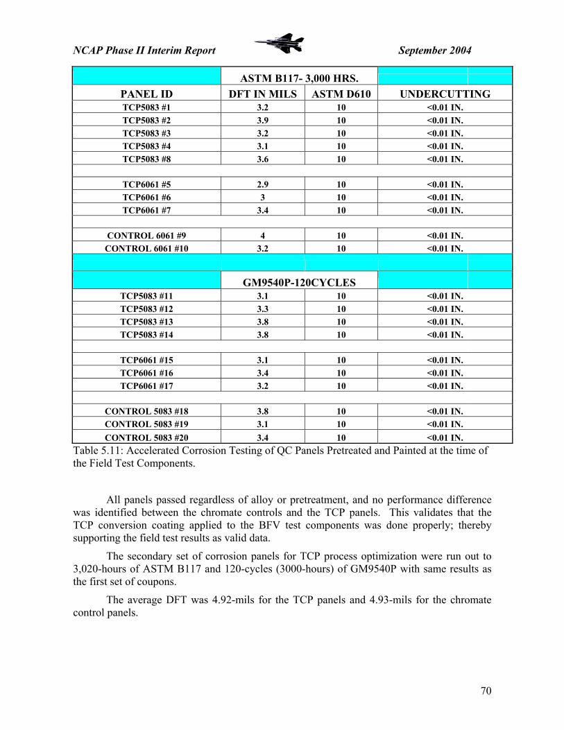
NCAP Phase II Interim Report September 2004
ASTM B117- 3,000 HRS.
PANEL ID DFT IN MILS ASTM D610 UNDERCUTTING TCP5083 #1 3.2 10 <0.01 IN. TCP5083 #2 3.9 10 <0.01 IN. TCP5083 #3 3.2 10 <0.01 IN. TCP5083 #4 3.1 10 <0.01 IN. TCP5083 #8 3.6 10 <0.01 IN.
TCP6061 #5 2.9 10 <0.01 IN. TCP6061 #6 3 10 <0.01 IN. TCP6061 #7 3.4 10 <0.01 IN.
CONTROL 6061 #9 4 10 <0.01 IN.
CONTROL 6061 #10 3.2 10 <0.01 IN.
GM9540P-120CYCLES TCP5083 #11 3.1 10 <0.01 IN. TCP5083 #12 3.3 10 <0.01 IN. TCP5083 #13 3.8 10 <0.01 IN. TCP5083 #14 3.8 10 <0.01 IN.
TCP6061 #15 3.1 10 <0.01 IN. TCP6061 #16 3.4 10 <0.01 IN. TCP6061 #17 3.2 10 <0.01 IN.
CONTROL 5083 #18 3.8 10 <0.01 IN. CONTROL 5083 #19 3.1 10 <0.01 IN. CONTROL 5083 #20 3.4 10 <0.01 IN.
Table 5.11: Accelerated Corrosion Testing of QC Panels Pretreated and Painted at the time of the Field Test Components.
All panels passed regardless of alloy or pretreatment, and no performance difference was identified between the chromate controls and the TCP panels. This validates that the TCP conversion coating applied to the BFV test components was done properly; thereby supporting the field test results as valid data.
The secondary set of corrosion panels for TCP process optimization were run out to 3,020-hours of ASTM B117 and 120-cycles (3000-hours) of GM9540P with same results as the first set of coupons.
The average DFT was 4.92-mils for the TCP panels and 4.93-mils for the chromate control panels.
70

NCAP Phase II Interim Report September 2004
5.3.5 – FIELD TESTS
5.3.5.1 – RESULTS
M2A3 Bradley Fighting Vehicle #258 – Parts were installed at APG, MD on August 30, 2003. This vehicle was scheduled for testing at APG Test Track facility. After testing at APG, this test vehicle was shipped to Huntsville, Al for modification, then returned to APG.
Brian Placzankis, Coatings and Corrosion Branch, Army Research Lab, APG, MD and Bill Nickerson, Inorganic Coatings, Naval Air Warfare Center, Aircraft Division, Patuxent River, MD inspected the vehicle at 6 months in January 2004 at the APG Test Track. Heather McNabnay, PMCS, and Tom Braswell, UDLP-York were also present for the inspection. No corrosion or adhesion loss was observed on any of the components at this time. Additionally, no undercutting or propagating paint loss was observed at damaged or dinged areas. This vehicle was again inspected at 12 months of service by Brian Placzankis, when it was returned to APG after installation of the Chassis Modernization/Embedded Diagnostics upgrade at Huntsville, Al. This mod kit is an upgrade to the hull electronics for the BFV’s, and requires the removal of the legacy steering yoke component. All other TCP components remain in service on the vehicle. While the vehicle evidenced much use, and was quite dirty and scuffed from testing, no corrosion or adhesion problems were reported, and no undercutting or additional paint adhesion loss was noted at damaged or dinged areas.
Figure 5.36: BFV M2A3 258 – APG, MD August 2004
71

NCAP Phase II Interim Report September 2004
M2A3 Bradley Fighting Vehicle #031 – Parts were installed at Ft. Benning, GA on October 16, 2003. This vehicle is a training vehicle for soldiers, and is frequently in the field. This vehicle is still fielded and used for training at Ft. Benning, GA.
Brian Placzankis, ARL, and Bill Nickerson, NAVAIR, inspected the vehicle at 9 months in May 2004 at the Ft. Benning Motor Pool. The vehicle had approximately 6500 kM put on it in training operations since fielding in October 2003. No corrosion or adhesion loss was observed on any of the components at this time. Additionally, no undercutting or propagating paint loss was observed at damaged or dinged areas. All TCP test components, including the legacy steering yoke, remain in service on the vehicle.
Figure 5.37: BFV M2A3 031 – Ft. Benning, GA May 2004
72

NCAP Phase II Interim Report September 2004
M3A3 Bradley Fighting Vehicle #086Y – Re-man parts were installed at Yuma Proving Ground (YPG) on February 18, 2004. This vehicle was scheduled for desert testing at the YPG vehicle test track; this terrain is very hard and rocky, leading to a lot of damage from dings and scrapes. This vehicle was transferred to APG, MD for the Chassis Modernization/Embedded Diagnostics modification kit installation on July 27, 2004.
Brian Placzankis, ARL, inspected the vehicle after almost 6 months in service with the test components, in July 2004 at APG. This vehicle had more dings, scrapes, and overall dirt and damage to the coating system than the other two test platforms. In several areas, the paint removal was down to exposure of the underlying TCP. See figure 5.38. This is again attributable to the extremely rocky terrain at YPG. No corrosion or adhesion loss was observed on any of the components at this time. Additionally, no undercutting or propagating paint loss was observed at damaged or dinged areas. All TCP test components, with the exception of the legacy steering yoke, remain in service on the vehicle.
Figure 5.38: BFV M3A3 086Y – APG, MD
73

NCAP Phase II Interim Report September 2004
Table 5.12: Vehicle Test Schedule – 28 July 2004
74

NCAP Phase II Interim Report September 2004
NAVAIR test parts remain on all three vehicles except for the steering yokes on 2AGR0258 and 3AGR00086Y at APG. Chassis Modernization/Embedded Diagnostics mod kits were installed and revised yokes replaced the NAVAIR steering yokes. There are no reported problems with NAVAIR test parts. 5.3.6 – STATUS No adhesion or corrosion issues have been reported with the test components. Testing will be continued for another 12 months, and possibly longer, to extract as much test data as possible. Currently, UDLP-York has expressed the intention to implement TCP as soon as a commercial source is qualified to MIL-DTL-81706B. PMCS has approved its use for spray applications only at this time. Approval for full immersion processing of the hull and turret structure is pending the results of the stress-corrosion-cracking test being conducted by United Defense CTC Santa Clara, CA. 5.3.6.1 – STRESS CORROSION CRACKING EVALUATION The SCC testing will be conducted by CTC Santa Clara, with testing oversight by the PMCS EMT. The purpose of this evaluation is to determine effect of hexavalent chrome, trivalent chrome, and the current steam cleaning process on SCC in AA7039 armor plating. The same 7039 plate, i.e. same heat lot, will be used to produce all samples. The samples will be modified to create short transverse cracks. The following variables will be examined, hexavalent chromium conversion coating, TCP conversion coating, pressure wash, and steam clean; with and without subsequent drying bake. This test will use fasteners and Belleville washers to create a controlled stress.
The sample size will be 8 inches wide, 12 inches long, and 1 inch thick. The selected proportional fastener torque will create 5-ksi tensile stress. Figure 5.39: SCC test specimen schematic
75
NCAP Phase II Interim Report September 2004
The test plan is as follows: create cracked samples from untreated AA7039, torque fasteners to the predetermined value, expose the samples to a salt spray environment, examine the samples daily for cracks using ultrasonic imaging in an attempt to grow a 2-inch crack.
The test samples, two replicates each (16 total), will then be processed with the following pretreatments, and re-exposed to a salt spray environment to monitor propagation of the crack. The pretreatments will be – none, MIL-C-5541 (chromate control), NAVAIR TCP, pressure wash, bake, and no bake. The results from this test will be presented to the PM Combat Systems EMT at the next quarterly meeting, with final status on chemical conversion coating by immersion processing to be determined at that time.
76

NCAP Phase II Interim Report September 2004
5.4 – US ARMY AVIATION 5.4.1 – BACKGROUND
In August of 2003, the Environmental, Engineering, and Logistics Oversight (EELO) office at AMCOM in Huntsville, AL put together a comprehensive panel test matrix to identify a non-chromate system for demonstration as a potential replacement coating system for their current chromate-based pretreatment and primer process. Currently, Army Aviation Depots spray chromate conversion coating, and paint with MIL-PRF-23377 C primer and MIL-C-46168 Ty IV CARC, a 2-component, polyurethane topcoat.
Panel preparation and coating was conducted by NAVAIR, Patuxent River, with AMCOM EELO, and ARL present from October 14-17, 2003. Panels were then shipped to ARL for corrosion and adhesion testing. All testing and evaluation was conducted under the oversight of PEO Aviation, AMCOM Materials, EELO, ARL, and NAVAIR.
The three alternative pretreatments selected for aluminum alloy testing were Alodine 5700, NAVAIR TCP, and PreKote. These pretreatments were evaluated over AA2024-T351 and AA7075-T651 alloys. The non-chrome primer alternative evaluated was MIL-PRF-85582 N since no qualified version of MIL-PRF-23377 N was available at the start of testing. All three pretreatments were evaluated under chromated primers (MIL-PRF-23377 C and MIL-PRF-85582 C) and the non-chromate MIL-PRF-85582 N. The potential replacement primers, MIL-PRF-85582 C and N were coated with the latest generation CARC topcoats, MIL-C-53039A Low VOC and MIL-DTL-64159 Type II to evaluate the coating “system” performance.
5.4.2 – LABORATORY TESTING
Testing was conducted by ARL at APG, MD by the Coatings and Corrosion Branch. Corrosion testing was conducted according to ASTM B117 neutral salt fog and GM9540P cyclic corrosion. All corrosion tests were run out to 3,000 hours, with regular evaluations by ARL and AMCOM. Adhesion testing was conducted according to ASTM D4541-95 pull-off and ASTM D3359 wet tape testing. Adhesion Testing was completed in early 2004 and corrosion testing was completed in July 2004. Table 5.13 shows the full aluminum coating system test matrix.
77

NCAP Phase II Interim Report September 2004
78
ALUMINUM AL2024-T3 ALUMINUM AL7075-T6
PNL ID 4
Control 5 6 7 8 9 10 11 12 13 14 15 13 Control 14 15 16 17 18 19
Panel Type 2024T3 2024T3 2024T3 2024T3 2024T3 2024T3 2024T3 2024T3 2024T3 2024T3 2024T3 2024T3 7075T6 7075T6 7075T6 7075T6 7075T6 7075T6 7075T6
Panel Pre-Treatment
MIL-C-5541
MIL-C-5541
MIL-C-5541
MIL-C-5541 TCP TCP TCP Alodine
5200 Alodine
5200 Alodine
5200 X-IT
PrecoatX-IT
Precoat MIL-C-
5541 MIL-C-
5541 MIL-C-
5541 TCP TCP TCP MIL-C-5541
Primer 23377C 85582N 85582N 85582N 85582C 85582N 85582N 85582C 85582N 85582N 85582C 85582N 23377C 85582N 85582N 85582C 85582N 85582N 85582C
Topcoat 46168IV 53039 64159II 64159IILSL 64159II 53039 64159II 64159II 53039 64159II 64159II 64159II 46168IV 53039 64159II 53039 53039 64159II 64159II
A Wet Adhesion - ASTM D 3359
2 2 2 2 2 2 2 2 2 2 2 2 2 2 2 2 2 2 2
B Salt Spray - ASTM B 117
5 5 5 5 5 5 5 5 5 5 5 5 5 5 5 5 5 5 5
C Pull-Off
ASTM D 4541-95
2 2 2 2 2 2 2 2 2 2 2 2 2 2 2 2 2 2 2
D GM 9540B - Method B
5 5 5 5 5 5 5 5 5 5 5 5 5 5 5 5 5 5 5
E Outdoor Exposure - FL
5 5 5 5 5 5 5 5 5 5 5 5 5 5 5 5 5 5 5
F QTRAC 10 10 10 10 10 10 10 10 10 10 10 10 10 10 10 10 10 10 10
G Electrochemical
Impedance Spectroscopy
N/A N/A N/A N/A N/A N/A N/A N/A N/A N/A N/A N/A N/A N/A N/A N/A N/A N/A N/A
Control Set 2 2 2 2 2 2 2 2 2 2 2 2 2 2 2 2 2 2 2
TOTAL
PANELS RQD PER SET
16 16 16 16 16 16 16 16 16 16 16 16 16 16 16 16 16 16 16
ALUMINUM - AL2024-T3 192 ALUMINUM - AL7075-T6 112
Table 5.13: AMCOM – NAVAIR PANEL TEST MATRIX OCTOBER 2003

NCAP Phase II Interim Report September 2004
5.4.2.1 – PULL-OFF ADHESION TESTING – ASTM D 4541-95
AA2024-T3 Pretreatment Primer Topcoat Adhesion (30
measurement Avg. – psi)
Alodine 1200S MIL-PRF – 23377 C MIL-C-46168 Ty IV 3205.67 +261.15
Alodine 1200S MIL-PRF – 85582 N MIL-C-53039A 2913 +213.79
Alodine 1200S MIL-PRF – 85582 N MIL-DTL-64159 Ty II 2609 +246.89
TCP MIL-PRF – 85582 C MIL-DTL-64159 Ty II 2739 +177.91
TCP MIL-PRF – 85582 N MIL-C-53039A 3064.33 +194.35
TCP MIL-PRF – 85582 N MIL-DTL-64159 Ty II 2579.33 +204.21
Alodine 5700 MIL-PRF – 85582 C MIL-DTL-64159 Ty II 2601.33 +304.37
Alodine 5700 MIL-PRF – 85582 N MIL-C-53039A 2563.67 +423.28
Alodine 5700 MIL-PRF – 85582 N MIL-DTL-64159 Ty II 1644 +275.91
PreKote MIL-PRF – 85582 C MIL-DTL-64159 Ty II 2388 +114.09
PreKote MIL-PRF – 85582 N MIL-DTL-64159 Ty II 2861 +272.94
Table 5.14: Pull-Off Adhesion Data – AA2024T3
AA7075-T6 Pretreatment Primer Topcoat Adhesion (30
measurement Avg. – psi)
Alodine 1200S MIL-PRF – 23377 C MIL-C-46168 Ty IV 3229 +317.41
Alodine 1200S MIL-PRF – 85582 N MIL-C-53039A 2993 +233.90
Alodine 1200S MIL-PRF – 85582 N MIL-DTL-64159 Ty II 2310 +173.90
TCP MIL-PRF – 85582 C MIL-C-53039A 2994.33 +427.70
TCP MIL-PRF – 85582 N MIL-C-53039A 2931 +201.93
TCP MIL-PRF – 85582 N MIL-DTL-64159 Ty II 2509.67 +149.05
Alodine 1200S MIL-PRF – 85582 C MIL-DTL-64159 Ty II 2712 +195.95
Table 5.15: Pull-Off Adhesion Data – AA7075T6
79

NCAP Phase II Interim Report September 2004
5.4.2.2 – WET TAPE ADHESION TESTING – ASTM D 3359
AA2024-T3 Pretreatment Primer Topcoat Panel 1 – 2
meas. Avg Panel 2 – 2 meas. Avg
Alodine 1200S MIL-PRF – 23377 C MIL-C-46168 Ty IV 5 5
Alodine 1200S MIL-PRF – 85582 N MIL-C-53039A 5 5
Alodine 1200S MIL-PRF – 85582 N MIL-DTL-64159 Ty II 4 4
TCP MIL-PRF – 85582 C MIL-DTL-64159 Ty II 4 5
TCP MIL-PRF – 85582 N MIL-C-53039A 5 5
TCP MIL-PRF – 85582 N MIL-DTL-64159 Ty II 5 4.5
Alodine 5700 MIL-PRF – 85582 C MIL-DTL-64159 Ty II 4.5 4 Blisters
Alodine 5700 MIL-PRF – 85582 N MIL-C-53039A 4 4.5 Blisters
Alodine 5700 MIL-PRF – 85582 N MIL-DTL-64159 Ty II 3.5 3.5
PreKote MIL-PRF – 85582 C MIL-DTL-64159 Ty II 3.5 3 Blisters
PreKote MIL-PRF – 85582 N MIL-DTL-64159 Ty II 4.5 4
Table 5.16: Wet Tape Adhesion Data – AA2024T3
AA7075-T6 Pretreatment Primer Topcoat Panel 1 – 2
meas. Avg Panel 2 – 2 meas. Avg
Alodine 1200S MIL-PRF – 23377 C MIL-C-46168 Ty IV 4.5 5
Alodine 1200S MIL-PRF – 85582 N MIL-C-53039A 5 5
Alodine 1200S MIL-PRF – 85582 N MIL-DTL-64159 Ty II 4.5 4.5
TCP MIL-PRF – 85582 C MIL-C-53039A 5 5
TCP MIL-PRF – 85582 N MIL-C-53039A 5 5
TCP MIL-PRF – 85582 N MIL-DTL-64159 Ty II 4.5 4.5
Alodine 1200S MIL-PRF – 85582 C MIL-DTL-64159 Ty II 5 4
Table 5.17: Wet Tape Adhesion Data – AA7075T6
80

NCAP Phase II Interim Report September 2004
5.4.2.3 – NEUTRAL SALT FOG TESTING – ASTM B 117
AA2024-T3 – Ratings According to ASTM D 1654 Procedure A Pretreatment Primer Topcoat Corrosion Results (5
panel Avg.)
Alodine 1200S MIL-PRF – 23377 C MIL-C-46168 Ty IV 8.6+0.89
Alodine 1200S MIL-PRF – 85582 N MIL-C-53039A 7.2+0.44 Alodine 1200S MIL-PRF – 85582 N MIL-DTL-64159 Ty II 7.4+0.55 TCP MIL-PRF – 85582 C MIL-DTL-64159 Ty II 9.0+0.00 TCP MIL-PRF – 85582 N MIL-C-53039A 5.8+0.84 TCP MIL-PRF – 85582 N MIL-DTL-64159 Ty II 5.0+0.71 Alodine 5700 MIL-PRF – 85582 C MIL-DTL-64159 Ty II 8.6+0.55 Alodine 5700 MIL-PRF – 85582 N MIL-C-53039A 6.4+1.34 Alodine 5700 MIL-PRF – 85582 N MIL-DTL-64159 Ty II 4.4+0.55 PreKote MIL-PRF – 85582 C MIL-DTL-64159 Ty II 7.4+0.55 PreKote MIL-PRF – 85582 N MIL-DTL-64159 Ty II 2.4+1.52
Table 5.18: Neutral Salt Fog Corrosion Data – AA2024T3
AA7075-T6 – Ratings According to ASTM D 1654 Procedure A Pretreatment Primer Topcoat Corrosion Results (5
panel Avg.)
Alodine 1200S MIL-PRF – 23377 C MIL-C-46168 Ty IV 9.0+0.0
Alodine 1200S MIL-PRF – 85582 N MIL-C-53039A 7.4+0.55 Alodine 1200S MIL-PRF – 85582 N MIL-DTL-64159 Ty II 7.8+0.45 TCP MIL-PRF – 85582 C MIL-C-53039A 8.8+0.45 TCP MIL-PRF – 85582 N MIL-C-53039A 7.2+0.45 TCP MIL-PRF – 85582 N MIL-DTL-64159 Ty II 7.2+0.45 Alodine 1200S MIL-PRF – 85582 C MIL-DTL-64159 Ty II 9.0+0.0
Table 5.19: Neutral Salt Fog Corrosion Data – AA7075T6
81
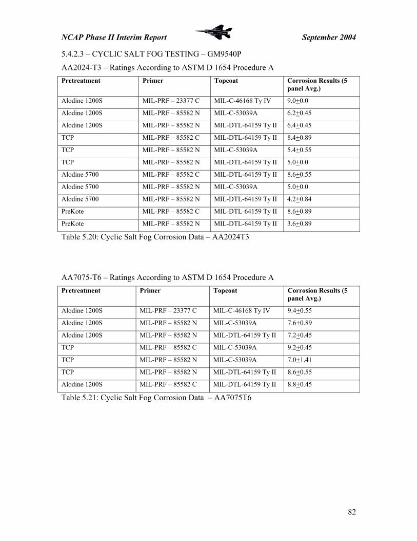
NCAP Phase II Interim Report September 2004
5.4.2.3 – CYCLIC SALT FOG TESTING – GM9540P
AA2024-T3 – Ratings According to ASTM D 1654 Procedure A Pretreatment Primer Topcoat Corrosion Results (5
panel Avg.)
Alodine 1200S MIL-PRF – 23377 C MIL-C-46168 Ty IV 9.0+0.0
Alodine 1200S MIL-PRF – 85582 N MIL-C-53039A 6.2+0.45
Alodine 1200S MIL-PRF – 85582 N MIL-DTL-64159 Ty II 6.4+0.45
TCP MIL-PRF – 85582 C MIL-DTL-64159 Ty II 8.4+0.89
TCP MIL-PRF – 85582 N MIL-C-53039A 5.4+0.55
TCP MIL-PRF – 85582 N MIL-DTL-64159 Ty II 5.0+0.0
Alodine 5700 MIL-PRF – 85582 C MIL-DTL-64159 Ty II 8.6+0.55
Alodine 5700 MIL-PRF – 85582 N MIL-C-53039A 5.0+0.0
Alodine 5700 MIL-PRF – 85582 N MIL-DTL-64159 Ty II 4.2+0.84
PreKote MIL-PRF – 85582 C MIL-DTL-64159 Ty II 8.6+0.89
PreKote MIL-PRF – 85582 N MIL-DTL-64159 Ty II 3.6+0.89
Table 5.20: Cyclic Salt Fog Corrosion Data – AA2024T3
AA7075-T6 – Ratings According to ASTM D 1654 Procedure A Pretreatment Primer Topcoat Corrosion Results (5
panel Avg.)
Alodine 1200S MIL-PRF – 23377 C MIL-C-46168 Ty IV 9.4+0.55 Alodine 1200S MIL-PRF – 85582 N MIL-C-53039A 7.6+0.89 Alodine 1200S MIL-PRF – 85582 N MIL-DTL-64159 Ty II 7.2+0.45 TCP MIL-PRF – 85582 C MIL-C-53039A 9.2+0.45 TCP MIL-PRF – 85582 N MIL-C-53039A 7.0+1.41 TCP MIL-PRF – 85582 N MIL-DTL-64159 Ty II 8.6+0.55 Alodine 1200S MIL-PRF – 85582 C MIL-DTL-64159 Ty II 8.8+0.45
Table 5.21: Cyclic Salt Fog Corrosion Data – AA7075T6
82

NCAP Phase II Interim Report September 2004
5.4.3 – FIELD TEST SYTEMS SELECTION
The current demonstration selection is to evaluate two non-chromate coating systems in field application on Army helicopters. Subject to approval from the PMA’s, the plan is to process six full CH-47 aircraft at two separate depots. Three aircraft will be processed at CCAD and three aircraft will be processed at the CT AVCRAD facility. Each site will process one control aircraft, to be primed with MIL-PRF-23377 C1 or C2, chromated epoxy primer. Table 5.18 outlines the planned demonstration coating systems.
Aircraft Pretreatment Primer Topcoat
CH-47 TCP MIL-PRF-23377 C MIL-C-53039A 1.5VOC
CH-47 TCP MIL-PRF-85582 N MIL-C-53039A 1.5VOC
CH-47 TCP MIL-PRF-23377 N MIL-C-53039A 1.5VOC
CH-47 Alodine 5700 MIL-PRF-23377 C MIL-DTL-64159 TyII
CH-47 Alodine 5700 MIL-PRF-85582 N MIL-DTL-64159 TyII
CH-47 Alodine 5700 MIL-PRF-23377 N MIL-DTL-64159 TyII
Table 5.22: AMCOM Coating System Demonstrations
5.4.3.1 – GENERAL GUIDELINES – AIRCRAFT CLEANING, SURFACE TREATMENT AND COATING
Aircraft will be inspected to identify coating problems and recorded in the aircraft coating test log (provided). Obvious corrosion, missing rivets, loose/flaking paint, etc. should all be noted. Aircraft shall be cleaned per normal operations at the facility and required maintenance accomplished prior to preparation for de-painting/painting operations.
Components normally removed prior to de-painting shall be removed and de-painted in accordance with normal procedures. Any aluminum substrate components removed for hand de-painting and processing shall follow the guidelines below for surface preparation and conversion coating of the aluminum substrate. Other non-aluminum components shall be prepared per normal procedures.
Once stripped, the aircraft shall be inspected for corrosion, and localized corrosion removed by hand abrasion (bristle disk, sander or hand sanding) no steel or iron abrasive should be used for removing corrosion on aluminum substrates, products like steel wool, stainless steel shot or grinding/abrading wheels, etc. should be avoided. Other identified flaws shall be repaired per normal procedures.
83

NCAP Phase II Interim Report September 2004
84
Cleaning of the aircraft is one of the most critical aspects of the TCP application and each step shall be closely followed to ensure a properly prepared surface prior to TCP application. All surfaces to be treated with TCP shall be cleaned to a water-break-free surface with a mild alkaline (pH 8-9, nothing over 9.5) cleaner conforming to MIL-PRF-85570 Type II or MIL-PRF-87937 Type II. Cleaners shall be diluted to the proper strength using deionized (DI) water to eliminate potential ion deposition on the cleaned substrate. If obvious signs of surface contamination remain, the cleaning process shall be repeated until a water-break-free surface is obtained. If there are signs of “acrylic smear” from Type V PMB an appropriate cleaner shall be substituted that will remove the contamination or the contaminants should be removed using medium grit Scotchbrite pads and an aqueous cleaner. Any alternate cleaner selection must be coordinated with the Research, Development Engineering Center, Materials Branch prior to use. Personnel shall avoid the use of high pH, strong alkaline cleaners to prevent damage to the aluminum substrates. Rinse water shall be deionized to eliminate conductive ions being trapped on the bare substrate creating potential corrosion initiation sites or sites where the TCP will not properly adhere. A deoxidation step may follow substrate cleaning for final surface preparation prior to TCP application. If a deoxidation process is used, the final rinse will also use DI water.
Following cleaning (and deoxidation, if used) the surface shall be treated with TCP. TCP shall be applied by hand sprayer ensuring the entire surface to be treated is completely coated with the TCP solution. The nominal dwell time prior to rinsing the TCP from the surface shall be 10-15 minutes. (Note: There is no obvious color change to the treated surface like Alodine 1200 series chromate conversion coatings. However, experienced personnel will be able to tell when the rinse should be performed. Properly applied, TCP leaves the treated surface with a subtle, iridescent blue-lavender color.) DI water shall be used for the TCP rinse step.
Following TCP treatment, the substrate shall be allowed to dehydrate for 16-24 hours. This is the proper “cure” time for the pretreatment. If scheduling is tight, a 4-hour dry time after processing can be implemented. Following dehydration, the aircraft shall be masked and coated with the proper primer and top-coating as required. 5.4.4 – STATUS EELO personnel will brief the cognizant PMA’s and AMCOM Materials in September 2004 to obtain approval for the CH-47 as the demonstration platform. If the PMA’s do not want to accept the results of the demo without a broader platform base, i.e. CH-60’s, AH-64E’s, etc., the planned number of aircraft will have to be increased. No changes to the processing sites should be necessary, regardless of the outcome of the PMA briefing. All processing will be done under the oversight of AMCOM Materials, and EELO. Bill Nickerson, NAVAIR will be present for technical processing support. William Alvarez, AMCOM EELO and Paul Robinson, (Titan Systems) EELO will evaluate the in-service performance of the test systems. Final approval for implementation must come from Materials and Engineering. Spray processing is planned to begin in the October-November 2004 timeframe, with the first 6 month in-service evaluation in the spring of 2005.

6.0 – IMPLEMENTATION OF ALTERNATIVES IN DoD AND NASA
6.1 – MILITARY AND INDUSTRIAL PRETREATMENT SPECIFICATIONS NAVAIR is currently in the process of revising the MIL-DTL-81706 qualification specification and the MIL-C-5541 quality control specification governing aluminum conversion coatings.
The proposed revisions are circulated through DoD and government contractors for comments and review, the inputs collated and organized, and a final revision written. Both revisions will allow the qualification and use of any non-chromate aluminum pretreatment that can pass the performance requirements for qualification. No changes have been made to the corrosion and adhesion testing requirements for aluminum conversion coatings.
Additionally, NAVAIR Materials will be working with the SAE-AMS Committee B toward the revision of the industrial aluminum conversion coating specification, also to include provisions for non-chromate coatings that meet the corrosion and adhesion performance requirements.
6.2 – ALODINETM 5700 6.2.1 – NASA
NASA has implemented a non-chromate coating system for use on their aluminum alloy Solid Rocket Boosters (SRB). The Space Shuttle SRB conducted a project to identify and qualify alternatives for the traditional, qualified chromate coating system and pretreatment. Testing gathered information on corrosion protection, bond strength, compatibility with other SRB materials, batch-to-batch consistency, and thermal environments data. Two pretreatments and two coating systems met the SRB program criteria. The recommended pretreatments were Henkel Alodine 5200/5700 and MacDermid Chemidize 727 ND. Alodine 5700 had very robust processing parameters and was recommended for first implementation as a pretreatment alternate.
NASA implemented a Hentzen non-chromate primer / Alodine 5700 pretreatment system in June 2002. This change affected all structural aluminum (2219, 6061, and 7075) parts of the solid rocket boosters. The first hardware flew in the fall of 2002.
For More Information Contact: Paul W. Hayes Phone: 321-853-5774 [email protected]
85

6.2.2 – US Army TACOM
The US Army TACOM has implemented Alodine 5200/5700 conversion coating on AA2024-T4 and AA2014-T6 road wheels for the Bradley Fighting Vehicle, the M113, and the MLRS. TACOM has also implemented Alodine 5200/5700 on Aluminum tracks for the M1A1 Abrams Tank. This technology has been implemented in the US Army Red River Army Depot's (RRAD) Rubber Products Operations since early 2003.
For More Information Contact: Heather McNabnay – PM CS Environmental Coordinator Ph: 586-753-2385 [email protected]
6.3 – PREKOTETM As of Feb. 2004, the F-16, T-37, T-38 and T-1 SPOs have approved the use of PreKote, and HQ Air Education and Training Command (AETC) has mandated its use on all AETC aircraft for which it’s approved. If a base, MAJCOM, or ALC decides to pursue using PreKote in their paint processes on other systems, it must obtain approval from the appropriate SPOs. AFCPCO will provide existing test results upon request to assist SPOs with the engineering decision whether to approve PreKote. AFCPCO continues to recommend chromated conversion coatings for optimum corrosion protection. Multiple laboratory tests, by various organizations, indicate PreKote is one of the best performing non-chromated surface treatments, but its corrosion protection is still less than that of chromated Alodine 1200S. Several other candidate materials are also being tested as possible alternatives to Alodine. It is likely that more than one material will meet AF needs. In cases where chromate cannot be used due to environmental restrictions, PreKote provides a low risk alternative. Note that all test results to date, current SPO approvals, and the assessment of low risk, are contingent on the use of a qualified chromated primer. When PreKote is used, corrosion inhibition comes only from the chromated primer. Past performance of non-chrome paint systems in AF use has been poor; and AFCPCO strongly recommends against the use of PreKote with non-chromated primers. Since application of PreKote is largely a manual process, the consistency of the process may be important to an overall satisfactory result. To achieve results equal to other weapon systems, we recommend adhering closely to application practices that have already been established. For More Information Contact: Richard H. Buchi Phone: 801-775-2993 [email protected]
86

6.3 – TCP 6.3.1 – NAVSEA
Based on the results of the outdoor exposure panel testing and the multi-year field demonstration at ACU-4, NSWCCD Materials has indicated that they will implement the TCP for pretreatment of aluminum alloys on the LCAC as soon as a commercial product is qualified to MIL-DTL-81706B. NAVSEA Materials is awaiting the issuance of the NAVAIR TCP approval letter for implementation.
For More Information Contact: Paul Dobias Phone: 215-897-1545 [email protected] 6.3.2 – USMC
The Expeditionary Fighting Vehicle is approaching the end of the SDD phase. Environmental, safety and health restrictions have led the program office to mandate the use of chromate and cadmium free coating systems. The program is scheduled to begin LRIP in FY06.
TCP has been selected as the pretreatment for the processing of the AA2519 hull and turret structures. Both the TCP and Alodine 5200/5700 have been approved by the PM for use on aluminum components by GDAMS and their vendors. The Marines’ AVTB is currently using Alodine 5700 pre-saturated wipes for coating system maintenance and repair touch-up applications on the SDD vehicles fielded there.
For More Information Contact: Kevin Clark – GDAMS Materials Phone: 703-490-7533 [email protected]
87

6.3.3 – NAVAIR Overall, the TCP technology is performing at least as well as the standard
chromate conversion coating in the demonstrations with the F/A-18’s and CH-46’s. NAVAIR Materials is planning to authorize the use of TCP under chromated primers, with the approval letter planned to issue by the end of 2004. FY05 efforts will focus on an extensive evaluation of new, non-chromate primer systems recently qualified to MIL-PRF-23377 Class N; with field testing over TCP planned if applicable based on laboratory testing.
As a result of the mixed field performance of the TCP with SPT, NAVAIR does not recommend the use of TCP with the SPT, and will not pursue implementation of a non-chromate conversion coating on the S-3 platform at this time. For More Information Contact: Craig Matzdorf – NAVAIR Materials Division Phone: 301-342-9372 [email protected]
6.4 – AC-130/131 6.4.1 – BOEING/AF Boeing Commercial Airplanes is using AC-131 on chromated aluminum rivets for B737 aircraft to improve paint adhesion to the rivets. The chromate plus AC-131 coating is applied to the rivets at the rivet manufacturer. Boeing Commercial Airplanes traditionally utilized Alodine 1000TM clear, chromate conversion coating for pretreatment of aluminum rivets on commercial aircraft. They were experiencing paint loss due to adhesion failure at the rivets. B737 aircraft produced since the spring of 2004 have had the chromate/AC-131 coated rivets used in the fuselage. The incidence of paint adhesion failures to the rivets has been significantly decreased with the new coating system. Boeing Commercial Airplanes is also performing scale-up and producibility trials of AC-131 with the goal of replacing the colorless chromated Alodine 1000 that is currently applied to new production commercial aircraft. Negotiations with customers to identify an operational evaluation are underway with application to production aircraft anticipated in mid 2005. For More Information Contact: Joe Osborne – Boeing-Seattle Phone: 425-237-8518 [email protected]
88

6.4.2 – NAVAIR/AF Although not part of the scope of the ESTCP Non-Chromate Aluminum
Pretreatments project, which focuses on pre-paint conversion coating applications for increased paint adhesion, corrosion protection, and electrical properties of aluminum alloys, a closely related use of hexavalent chromium coatings is as a pre-adhesive treatment on aluminum alloys prior to structural bonding applications. Traditionally, adhesive bonding is done with chromated aluminum surfaces.
This Joint Service program (PP-0204) is being is also being funded by the generous support of the ESTCP office. This project is using repair demonstrations to validate the use of sol-gel based surface preparations for adhesive bonding that were developed under SERDP programs PP-130 and PP-1113. This work has focused on the implementation of repair practices developed for a commercial, epoxy functional sol-gel – AC-130 from AC Tech – in applications where the sol-gel could be used to replace a hazardous surface preparation method with no reduction in expected adhesive bond performance. Furthermore, the use of the AC-130 system has the added benefits of simplicity and process robustness, especially when compared to difficult and dangerous surface preparation methods that use strong acids and hexavalent chromium. These two factors have been combined to guide the use of sol-gel in DoD repair applications to both replace hazardous surface preparation methods and to supplant obsolescent repair methods with inferior structural performance. The use of this sol-gel is coupled with a zero-VOC primer material in most applications to provide a surface protection scheme for steel, aluminum, or titanium that is suitable for structural bonding. In laboratory testing, this combination has been used to demonstrate bonded strength and durability performance that exceeds the best existing treatments for the alloys evaluated. Through the demonstration process, this is being translated into a robust repair process that allows repair artisans to restore components to near pristine condition. To this end, demonstration of process utility has occurred with repair development on a number of weapon systems for the tri-service partners, and off-program transitions have been deployed with success in the field. Current work in this program has targeted high-impact transitions that will provide the most benefit per dollar spent, and will enable the services to move sol-gel technology through their logistics and repair systems as quickly as possible. For More Information Contact: Matt Tillman – NAVAIR Materials Division Phone: 301-995-7561 [email protected]
89

THIS PAGE LEFT BLANK INTENTIONALY
90

7.0 – CONCLUSIONS AND RECOMMENDATIONS
All the alternatives being demonstrated are aqueous solutions designed to deposit a conversion coating on aluminum alloy substrates to enhance paint adhesion and painted corrosion performance. Alternatives face the challenge of the low cost and ease of application of the chromate conversion coatings while providing a coating that provides acceptable technical performance. Along with technical performance, processing and toxicity issues are important to consider in capturing the overall impact of an alternative.
There are currently four non-chromate alternatives in various stages of validation or implementation. Alodine 5200/5700, PreKote, and AC-130/131 provide paint adhesion and painted corrosion protection, and are all non-chromium chemistries. The TCP provides both painted and unpainted corrosion protection as well as electrical conductivity in corrosive environments. However, TCP does contain trivalent chromium, and users will need to balance total chromium waste-water requirements with technical performance requirements when deciding on implementation of TCP. TCP and Alodine 5200/5700 provide the most process flexibility, as they can be applied like a chromate conversion coating, by immersion, spray, or wipe-on methods. AC-130/131 can be used in spray applications. PreKote must be manually applied for proper coating performance.
All of the demonstration coatings have shown good paint adhesion and corrosion performance when used under chromated primers. The PreKote and the AC-130/131 have not yet been demonstrated in high corrosion environments. The TCP and Alodine 5200/5700 have shown good paint adhesion and painted corrosion performance when used under both chromated and non-chromated primers. TCP and Alodine 5200/5700 have performed well in high corrosion environment testing. The exception to this is the performance of the TCP on one of the four NAVAIR S-3 demonstrations using non-chromated Self-Priming Topcoat. A positive outcome of the S-3 testing was the finding that 500-hour SO2 salt-fog was not enough to discriminate between the chromated and non-chromate coating systems. By extending the test to 1000-hours, additional corrosion and blistering were observed with fully non-chromated coating systems. This is a clear example of a test designed to evaluate the performance of chromate-based materials, which are not typically tested to failure, but to minimum performance standards.
It is therefore critical with any new non-chromate material that it be tested to failure against the chromated control. Additionally, any new coating application should be demonstrated and validated by field-testing for each operational environment where implementation is being considered. Only then can the complete technical performance of a coating or coating system be determined.
Implementation of any alternative must take into consideration the costs, process, health and safety, laboratory and field testing performance, and the specific coating system application and operational environment.
91

REFERENCES Section 1.2 – ESTCP NCAP Phase I Report, C. Matzdorf, July 2003 Section 3.0 – “Protective Coatings Coupon Project – Ratings and Pictures, J. Curran, Jan. 2004 Section 4.1 – AFCPCO Position Paper, D. Kinzie, O. Jett, D. Buchi, M. Spicer, Feb. 2004 Section 4.2.2 – “TCP Application and Processing Notes”, T. Woods, July 1999; T. Woods, Aug. 1999 Section 4.2.3 – “In-Service Field Inspection Notes”, T. Woods, May 2001; T. Woods, Dec. 2001; J. Benfer, Jan. 2002 Section 4.3.2 – “TCP Application and Processing Notes”, T. Woods, Nov. 2000 Section 4.3.3 – “In-Service Field Inspection Notes”, T. Woods, July 2001; T. Woods, Oct. 2001 Section 4.3.3 – “Trip Report AM005”, K. Kovaleski, C. Matzdorf, Mar. 2004 Section 4.4.2 – “Materials Engineering Analysis Report – Processing”, J. Whitfield, Oct. 2000; J. Whitfield, Nov. 2001 Section 4.4.3 – “Materials Engineering Analysis Report – Status”, J. Whitfield, Jan. 2004 Section 4.5 – ESTCP NCAP Phase I Report, C. Matzdorf, July 2003 Section 4.6 – “Advanced Aircraft Corrosion Protection Final Report for period September 2002 through April 2003”, J. Osborne, Prepared by Boeing for Universal Technologies Corporation under contract #02-S470-009-C1, April 25, 2003 Section 4.6 – “Advanced Aircraft Corrosion Protection Update Notes”, J. Osborne, Oct. 2004 Section 5.1 – “Trivalent Chromium Pretreatment (TCP) testing for the Landing Craft, Air Cushioned (LCAC) Program Update Notes”, P. Dobias, July 2004 Section 5.2.2 – “Inorganic Coatings Team Laboratory Report LR02-001”, C. Matzdorf, Aug. 2001 Section 5.2.3 – “Inorganic Coatings Team Test Matrix M1_07”, C. Matzdorf, Jan. 2002 Section 5.2.4 – “Inorganic Coatings Team Laboratory Reports”, LR02-007, B. Nickerson, Aug. 2002; LR03-006, C. Matzdorf, Aug. 2003
92

Section 5.2.5 – “EFV Hull and Turret Processing Notes”, B. Nickerson, C. Matzdorf, K. Clark, D. Gerty, S. Bettadapur, A. Hilgeman, S. Brown, 2001-2004 Table 5.5 – “EFV SDD Hull and Turret Paint Plan”, K. Clark, Feb. 2003 Section 5.2.8 – “In-Service Field Evaluations”, C. Matzdorf, Aug. 2003; B. Nickerson, K. Clark, Mar. 2004; B. Nickerson, K. Clark, S. Bettadapur, May 2004 Section 5.3 – “US Army PM Combat Systems Environmental Management Team Meeting Presentations”, T. Braswell, B. Nickerson, J. Kinchen, H. McNabnay, J. Dorsch, Oct. 2003, May 2004 Section 5.3.3 – “US Army M2A3/M3A3 Bradley Fighting Vehicle Component Processing Notes”, T. Braswell, H. McNabnay, B. Nickerson, Aug. 2003; T. Braswell, B. Nickerson; Nov. 2003 Section 5.3.4 – “CTC York Adhesion and Corrosion Testing Results”, D. Russo, T. Braswell, Sep. 2003 Section 5.3.5 – “US Army PM Combat Systems Environmental Management Team Meeting – ARL Update”, B. Placzankis, Aug. 2004 Section 5.3.6 – “US Army PM Combat Systems Environmental Management Team Meeting – UDLP CTC Update”, J. Dorsch, Aug. 2004 Section 5.4 – “US Army Aviation Non-Chrome Coating System Test Program – Master Schedule”, F. Baker, J. Escarsega, C. Matzdorf, B. Nickerson, M. Kane, W. Alzarez, T. Helton, P. Robinson, Oct. 2003 Section 5.4.2 – “Accelerated Corrosion Performance for Aviation Coating Systems – ARL”, C. Miller, B. Placzankis, In-Progress 2004 Section 5.4.3 – “Field Tests/Coatings Systems Selection Meeting – NAVAIR and AMCOM”, W. Alvarez, P. Robinson, T. Helton, B. Nickerson, C. Matzdorf, July 2004 Section 5.4.3.1 – “Aircraft Cleaning, Surface Treatment, and Coating Guide”, P. Robinson, T. Helton, June 2004 Technology Demonstration Plan “Demonstration and Validation of Non-Chromate Aluminum Pretreatments,” Science Applications International Corporation for the Naval Aviation Systems Command (NAVAIR), May 2002. Joint Test Protocol, “Joint Test Protocol for Validation of Non-Chromate Aluminum Pretreatments,” Naval Air Systems Command Inorganic Coatings Team, December 13, 2000.
93

MIL-DTL-81706A, “Chemical Conversion Materials for Coating Aluminum and Aluminum Alloys,” U.S. Department of Defense, Washington, DC, 1999. MIL-PRF-85582, “Primer Coatings, Epoxy, Waterborne,” U.S. Department of Defense, Washington, DC, September 1997. MIL-P-53030A, “Primer, Epoxy Coating, Water Reducible, Lead and Chromate Free,” Revision A, Amendment 2, U.S. Department of Defense, Washington, DC, 1992. MIL-P-53022-10, “Primer, Epoxy Coating, Corrosion Inhibiting, Lead and Chromate Free,” U.S. Department of Defense, Washington DC, February 1992. MIL-PRF-23377G, “Primer Coatings, Epoxy, High Solid,” U.S. Department of Defense, Washington, DC, September 1994. ASTM D1654, “Standard Method for Evaluation of Painted or Coated Specimens Subjected to Corrosive Environments,” ASTM, West Conshohocken, PA, 1984. ASTM F22-65, “Standard Test Method for Hydrophobic Surface Films by the Water-Break Test, ASTM, West Conshohocken, PA, 1965. Lab Report #LR02-004, “Coating Weights and Processing of Alternatives for ESTCP NCAP Project PP0025,” Craig Matzdorf ESTCP for the NCAP Project PP0025, July 24, 2002. MIL-C-53039A, “Coating, Aliphatic Polyurethane, Single Component, Chemical Agent Resistant,” U.S. Department of Defense, Washington DC, May 1993. MIL-PRF-85285, “Coating, Polyurethane, High Solids,” U.S. Department of Defense, Washington, DC, April 1997. MIL-T-81772, “Thinner, Aircraft Coating,” U.S. Department of Defense, Washington, DC, Oct 25, 1991. ASTM B117, "Standard Method of Practice for Operating Salt Spray (Fog) Apparatus," ASTM, West Conshohocken, PA, 1990. Placzankis, Brian E. and Miller, Chris E., “ASTM B 117 Screening of Non-Chromate Conversion Coatings on Aluminum Alloys 2024, 2219, 5083, and 7075 using DoD Paint Systems,” Army Research Laboratory Report, Aberdeen Proving Ground, Maryland. GM 9540P, “Accelerated Corrosion Test; GM 9540P,” General Motors Engineering Standards, 1997. ASTM G85 “Standard Practice for Modified Salt Spray (Fog) Testing,” ASTM International, West Conshohocken, PA, 2002.
94

Matzdorf, Craig and Kane, Dr. Michael J., “Evaluation of Non-Chromate Conversion Coatings in DoD Coating Systems using ASTM G85 SO2 Salt Fog,” NAVAIR, Patuxent River, MD. Plazankis, Brian E., Miller, Chris E., Matzdorf, Craig, “Analysis of Non-chromate Conversion Coatings on Aluminum Alloys 2024, 5083, and 7075 with DoD Coatings Using GM 9540P Cyclic Accelerated Corrosion Exposure,” Proceedings from the Triservice Conference on Corrosion, San Antonio, TX, January 2002. ASTM D1654-92, “Standard Test Method for Evaluation of Painted or Coated Specimens Subjected to Corrosive Environments,” ASTM, West Conshohocken, PA, 1992. FED-STD-141, “Paint, Varnish, Lacquer, and Related Materials: Methods of Inspection, Sampling, and Testing,” 1986. ASTM D3359, “ Standard Method for Measuring Adhesion by Tape Test, Method A & B” ASTM International, 1997. “Demonstration Report (Technology Improvement Report) for Non-Chromate Pretreatments of Non-Ferrous Metals,” National Defense Center for Environmental Excellence/Concurrent Technologies Corporation for the Environmental Security Technology Certification Program, September 20, 2002. “Acute Oral Toxicity/LD50 in Rats,” MB 02-10327.01, Cerven, Daniel R. for MB Research Laboratories, 2002. “Acute Dermal Toxicity/LD50 in Rabbits,” MB 02-10327.02, Cerven, Daniel R. for MB Research Laboratories, 2002. “Justification Report (Technology Improvement Report) for Non-Chromate Pretreatments of Non-Ferrous Metals,” National Defense Center for Environmental Excellence/Concurrent Technologies Corporation for the Environmental Security Technology Certification Program, September 24, 2002. “Non-chromated Conversion Coatings for Weapon Systems Rework and Repair,” National Defense Center for Environmental Excellence/Concurrent Technologies Corporation for the Environmental Security Technology Certification Program, September 24, 2001. Zook L., Clayton C., and Raley R, “Alternate SRB Aluminum Coating System Qualification Test Report,” CPC-025-00MP, United Space Alliance, May 1, 2000 Buchi, Richard H., Patterson, Ken, and Gowers, Clyde J. “Non-Chromate Conversion Coating,” Ogden Air Logistics Center, April 3, 1998.
95

96
MIL-P-24441B Ty III F150/151, “Epoxy Polyamide Formula 150 & Formula 151,” U.S. Department of Defense, Washington, DC, 1994. Osborn, Joseph H., “Advanced Aircraft Corrosion Protection Final Report for period September 2002 through April 2003”, Prepared by Boeing for Universal Technologies Corporation under contract #02-S470-009-C1, April 25, 2003.