non-coherent pulse compression aperiodic and periodic ...nadav/pdf-files/non_coherent... ·...
TRANSCRIPT
IET Radar, Sonar & Navigation
Research Article
Non-coherent pulse compression — aperiodicand periodic waveforms
IET Radar Sonar Navig., 2016216 & The Institution of Engine
ISSN 1751-8784Received on 26th January 2015Revised on 28th May 2015Accepted on 21st June 2015doi: 10.1049/iet-rsn.2015.0046www.ietdl.org
Nadav Levanon1 ✉, Itzik Cohen1, Nadav Arbel2, Avinoam Zadok2
1Electrical Engineering – Systems, Tel-Aviv University, Tel-Aviv, Israel2School of Engineering, Bar-Ilan University, Ramat-Gan, Israel
✉ E-mail: [email protected]
Abstract: The growing interest in adopting pulse compression waveforms to non-coherent radar and radar-like systems(e.g. lidar) invites this update and review. The authors present different approaches of designing on–off {1, 0} codedenvelopes of transmitted waveforms whose returns can be envelope detected and non-coherently processed. Twoapproaches are discussed for the aperiodic case: (a) Manchester encoding and (b) mismatched reference. For theperiodic case, on–off sequences are described, which produce perfect periodic cross-correlation when cross-correlatedwith one or more integer number of periods of a two-valued reference sequence {1, −b}. This study providescomprehensive rules for designing periodic on–off waveforms and their references. The periodic waveform’s high-average duty cycle (over 50%) makes it a ‘quasi continuous wave (CW) non-coherent waveform’, which avoids thepulse–train conflict between average power and unambiguous range. Good experimental results with a laser rangefinder are presented. Reports on other uses are quoted.
1 Introduction
Direct-detection lidar, non-coherent (magnetron) radar, sonar,ultrasound, ground penetrating radar, optical masks and opticaltime domain reflectometer (OTDR) are examples of non-coherentradar or radar-like systems that are likely to use unmodulatedpulses and detect the intensity (envelope) of their reflection.Aperiodic on–off pulse sequences for such systems were discussedunder the topic of non-coherent pulse compression (NCPC) [1].Complementary pairs [2] and periodic sequences [3, 4] were alsodiscussed. The basic approach of creating suitable waveforms forthe aperiodic case is to create a unipolar sequence by Manchesterencoding a binary sequence known to be useful in coherent pulsecompression; or by Manchester encoding a binary complementarypair. The reference sequence with which the received signal iscross-correlated could be either a binary bipolar version of theManchester-encoded sequence, or a straightforward mismatchedfilter (MMF) designed for the unipolar sequence. In its first part,the present paper reviews and compares the aperiodic waveformsand their different processing approaches. The second part presentsnew results for the periodic case. The importance of periodic on–off waveforms stems from the fact that with proper periodicreference sequences, periodic unipolar sequences can yield perfectperiodic cross-correlation (PPCC) whose sidelobes are identicallyzero. Periodic sequences also exhibit high duty cycle which maybe attractive to some applications and a hindrance to others.Moreover, described are unique periodic coherent waveforms thatcan be processed coherently or incoherently and in both casesproduce PPCC.
2 Aperiodic on–off waveforms
The discussion and comparison of on–off aperiodic waveforms andtheir processing approaches will start with a simple example basedon the well-known coherent pulse compression sequence Barker 13
S1 = +1 + 1 + 1 + 1 + 1 − 1 − 1 + 1
+ 1 − 1 + 1 − 1 + 1(1)
There are at least two ways in which Barker 13 can be transformed toan on–off transmitted signal: (a) Manchester encoding (+1 → 1 0,−1→ 0 1) and (b) transmitting only the positive elements(+1 → 1, −1→ 0). We will now discuss both approaches.
2.1 Transmitting Manchester-encoded barker 13
Manchester encoding of the sequence S1 will create the sequence S2that can be easily transmitted by pulses from a non-coherent source
S2 = 1 0 1 0 1 0 1 0 1 0 0 1 0 1 1 0 1 0 0 1 1 0 0 1 1 0 (2)
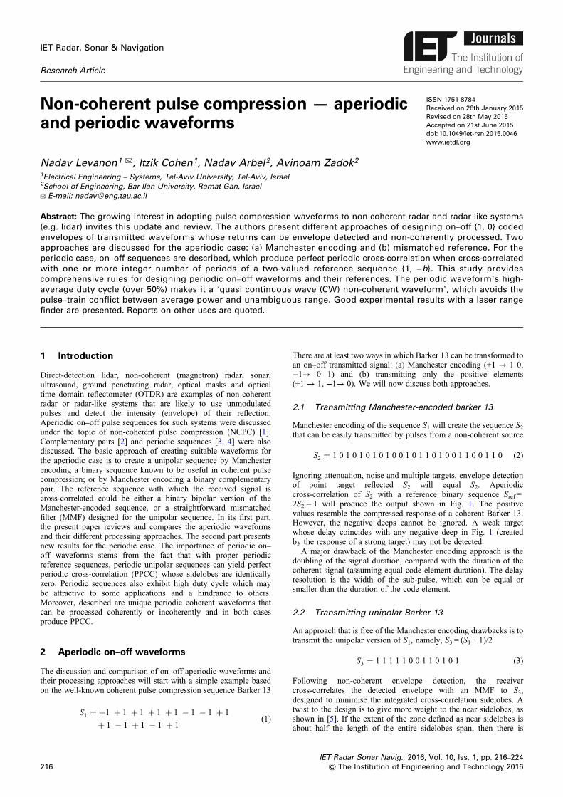
Ignoring attenuation, noise and multiple targets, envelope detectionof point target reflected S2 will equal S2. Aperiodiccross-correlation of S2 with a reference binary sequence Sref =2S2− 1 will produce the output shown in Fig. 1. The positivevalues resemble the compressed response of a coherent Barker 13.However, the negative deeps cannot be ignored. A weak targetwhose delay coincides with any negative deep in Fig. 1 (createdby the response of a strong target) may not be detected.
A major drawback of the Manchester encoding approach is thedoubling of the signal duration, compared with the duration of thecoherent signal (assuming equal code element duration). The delayresolution is the width of the sub-pulse, which can be equal orsmaller than the duration of the code element.
2.2 Transmitting unipolar Barker 13
An approach that is free of the Manchester encoding drawbacks is totransmit the unipolar version of S1, namely, S3 = (S1 + 1)/2
S3 = 1 1 1 1 1 0 0 1 1 0 1 0 1 (3)
Following non-coherent envelope detection, the receivercross-correlates the detected envelope with an MMF to S3,designed to minimise the integrated cross-correlation sidelobes. Atwist to the design is to give more weight to the near sidelobes, asshown in [5]. If the extent of the zone defined as near sidelobes isabout half the length of the entire sidelobes span, then there is
, Vol. 10, Iss. 1, pp. 216–224ering and Technology 2016
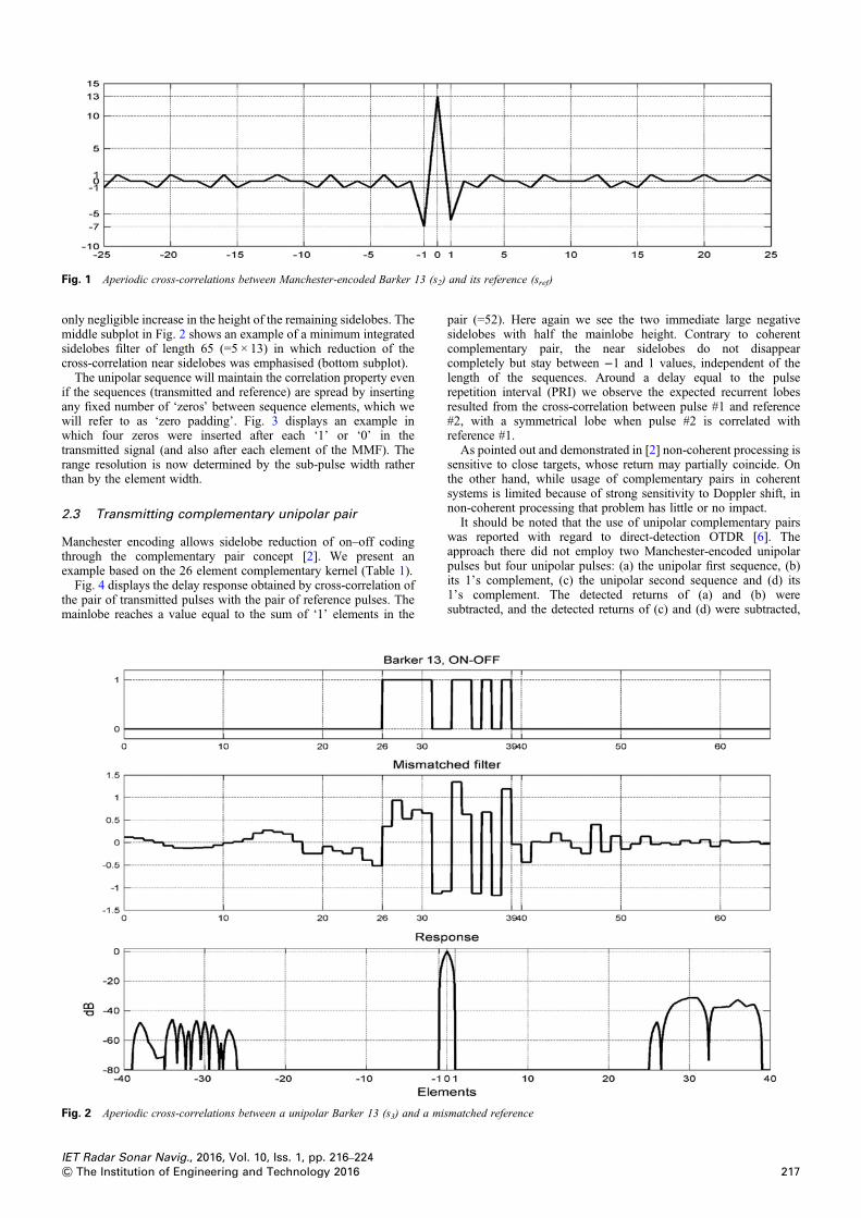
Fig. 1 Aperiodic cross-correlations between Manchester-encoded Barker 13 (s2) and its reference (sref)
only negligible increase in the height of the remaining sidelobes. Themiddle subplot in Fig. 2 shows an example of a minimum integratedsidelobes filter of length 65 (=5 × 13) in which reduction of thecross-correlation near sidelobes was emphasised (bottom subplot).
The unipolar sequence will maintain the correlation property evenif the sequences (transmitted and reference) are spread by insertingany fixed number of ‘zeros’ between sequence elements, which wewill refer to as ‘zero padding’. Fig. 3 displays an example inwhich four zeros were inserted after each ‘1’ or ‘0’ in thetransmitted signal (and also after each element of the MMF). Therange resolution is now determined by the sub-pulse width ratherthan by the element width.
2.3 Transmitting complementary unipolar pair
Manchester encoding allows sidelobe reduction of on–off codingthrough the complementary pair concept [2]. We present anexample based on the 26 element complementary kernel (Table 1).
Fig. 4 displays the delay response obtained by cross-correlation ofthe pair of transmitted pulses with the pair of reference pulses. Themainlobe reaches a value equal to the sum of ‘1’ elements in the
Fig. 2 Aperiodic cross-correlations between a unipolar Barker 13 (s3) and a mi
IET Radar Sonar Navig., 2016, Vol. 10, Iss. 1, pp. 216–224& The Institution of Engineering and Technology 2016
pair (=52). Here again we see the two immediate large negativesidelobes with half the mainlobe height. Contrary to coherentcomplementary pair, the near sidelobes do not disappearcompletely but stay between −1 and 1 values, independent of thelength of the sequences. Around a delay equal to the pulserepetition interval (PRI) we observe the expected recurrent lobesresulted from the cross-correlation between pulse #1 and reference#2, with a symmetrical lobe when pulse #2 is correlated withreference #1.
As pointed out and demonstrated in [2] non-coherent processing issensitive to close targets, whose return may partially coincide. Onthe other hand, while usage of complementary pairs in coherentsystems is limited because of strong sensitivity to Doppler shift, innon-coherent processing that problem has little or no impact.
It should be noted that the use of unipolar complementary pairswas reported with regard to direct-detection OTDR [6]. Theapproach there did not employ two Manchester-encoded unipolarpulses but four unipolar pulses: (a) the unipolar first sequence, (b)its 1’s complement, (c) the unipolar second sequence and (d) its1’s complement. The detected returns of (a) and (b) weresubtracted, and the detected returns of (c) and (d) were subtracted,
smatched reference
217
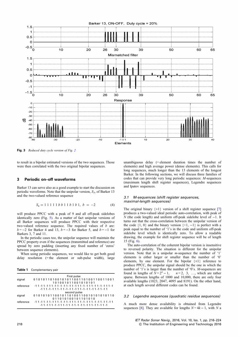
Fig. 3 Reduced duty cycle version of Fig. 2
to result in a bipolar estimated versions of the two sequences. Thosewere then correlated with the two original bipolar sequences.
3 Periodic on–off waveforms
Barker 13 can serve also as a good example to start the discussion onperiodic waveforms. Note that the unipolar version, S3, of Barker 13and the two-valued reference sequence
S4 = 1 1 1 1 1 b b 1 1 b 1 b 1, b = −2 (4)
will produce PPCC with a peak of 9 and all off-peak sidelobesidentically zero (Fig. 5). As a matter of fact unipolar versions ofall Barker sequences will produce PPCC with their respectivetwo-valued reference sequence. The required values of b are:b =−2 for Barker 4 and 13, b =−3 for Barker 5, and b =−1 forBarkers 3, 7 and 11.
In the periodic cases too, the unipolar sequence will maintain thePPCC property even if the sequences (transmitted and reference) arespread by zero padding (inserting any fixed number of ‘zeros’between sequence elements).
When using periodic sequences, we would like to get both gooddelay resolution (= the element or sub-pulse width), large
Table 1 Complementary pair
First pulsesignal 0 1 0 1 0 1 1 0 1 0 0 1 0 1 0 1 1 0 0 1 1 0 1 0 0 1 1 0 0 1 1 0 0 1
1 0 1 0 0 1 0 1 1 0 0 1 0 1 0 1 0 1reference -1 1 -1 1 -1 1 1 -1 1 -1 -1 1 -1 1 -1 1 1 -1 -1 1 1 -1 1 -1 -1 1 1 -1
-1 1 1 -1 -1 1 1 -1 1 -1 -1 1 -1 1 1 -1 -1 1 -1 1 -1 1 -1 1second pulse
signal 0 1 0 1 0 1 0 1 1 0 0 1 0 1 1 0 1 0 0 1 1 0 0 1 0 1 0 1 0 1 0 1 1 00 1 1 0 1 0 1 0 0 1 0 1 1 0 1 0 1 0
reference -1 1 -1 1 -1 1 -1 1 1 -1 -1 1 -1 1 1 -1 1 -1 -1 1 1 -1 -1 1 -1 1 -1 1-1 1 -1 1 1 -1 -1 1 1 -1 1 -1 1 -1 -1 1 -1 1 1 -1 1 -1 1 -1
218
unambiguous delay (= element duration times the number ofelements) and high average power (dense elements). This calls forlong sequences, much longer than the 13 elements of the longestBarker. In the following sections, we will discuss three families ofcodes that can provide very long periodic sequences: M-sequences(maximum length shift register sequences), Legendre sequencesand Ipatov sequences.
3.1 M-sequences (shift register sequences,maximal-length sequences)
The original binary {±1} version of a shift register sequence [7]produces a two-valued ideal periodic auto-correlation, with peak ofN (the code length) and uniform off-peak sidelobe level of −1. Itturns out that the cross-correlation between the unipolar version ofthe code {1, 0} and the binary version {+1, −1} is perfect with apeak equal to the number of ‘1’s in the code and uniform off-peaksidelobe level which is identically zero. To allow a readabledrawing, the example for shift register sequence will be of length15 (Fig. 6).
The auto-correlation of the coherent bipolar version is insensitiveto reversed polarity. The situation is different for the unipolarversion. Note that in a unipolar m-sequence the number of ‘1’elements is either larger or smaller than the number of ‘0’elements, by one element. For the bipolar {±1} reference toproduce PPCC, the unipolar signal should be the one in which thenumber of ‘1’s is larger than the number of ‘0’s. M-sequences arefound in lengths of N = 2n− 1, n = 2, 3, …, which are rathersparse. Between lengths of 1000 and 10,000, there are only fouravailable lengths (1023, 2047, 4095 and 8191). On the other hand,at each length several different codes can be found.
3.2 Legendre sequences (quadratic residue sequences)
A much more dense availability is obtained from Legendresequences [8]. They are available for lengths N = 4k− 1, with N a
IET Radar Sonar Navig., 2016, Vol. 10, Iss. 1, pp. 216–224& The Institution of Engineering and Technology 2016
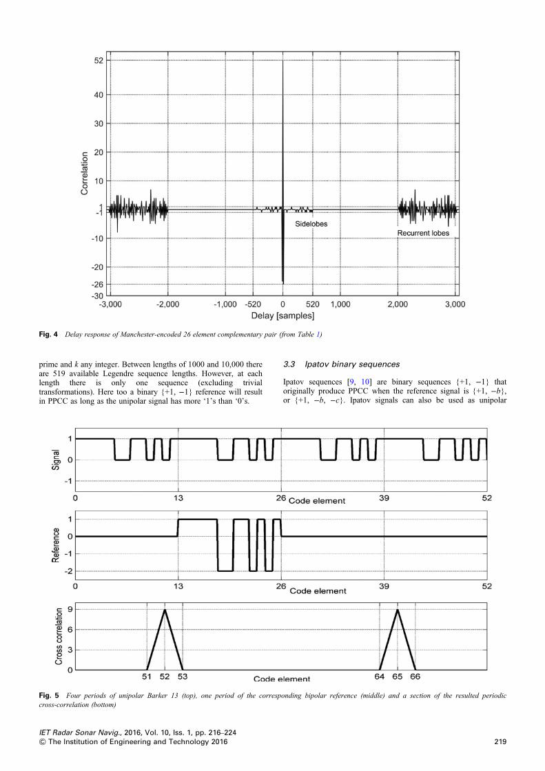
Fig. 4 Delay response of Manchester-encoded 26 element complementary pair (from Table 1)
prime and k any integer. Between lengths of 1000 and 10,000 thereare 519 available Legendre sequence lengths. However, at eachlength there is only one sequence (excluding trivialtransformations). Here too a binary {+1, −1} reference will resultin PPCC as long as the unipolar signal has more ‘1’s than ‘0’s.
Fig. 5 Four periods of unipolar Barker 13 (top), one period of the correspcross-correlation (bottom)
IET Radar Sonar Navig., 2016, Vol. 10, Iss. 1, pp. 216–224& The Institution of Engineering and Technology 2016
3.3 Ipatov binary sequences
Ipatov sequences [9, 10] are binary sequences {+1, −1} thatoriginally produce PPCC when the reference signal is {+1, −b},or {+1, −b, −c}. Ipatov signals can also be used as unipolar
onding bipolar reference (middle) and a section of the resulted periodic
219
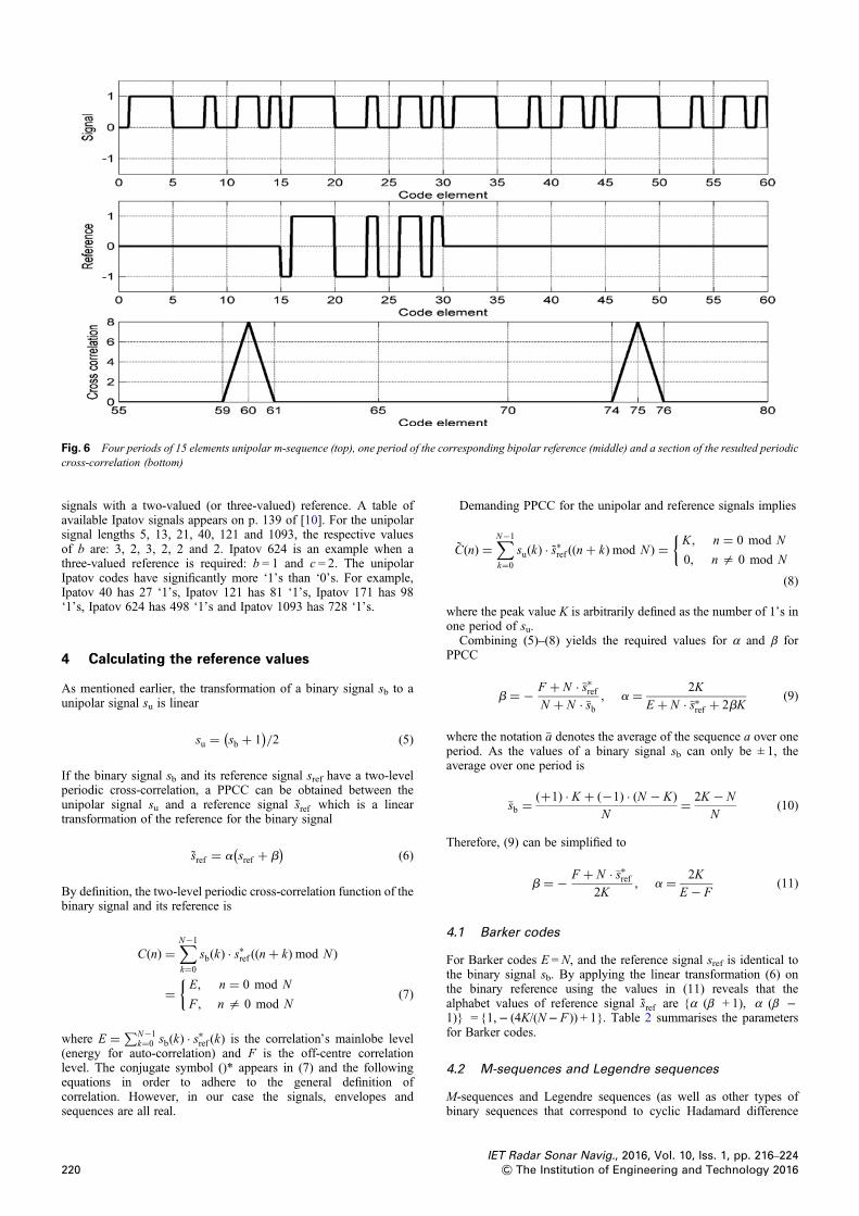
Fig. 6 Four periods of 15 elements unipolar m-sequence (top), one period of the corresponding bipolar reference (middle) and a section of the resulted periodiccross-correlation (bottom)
signals with a two-valued (or three-valued) reference. A table ofavailable Ipatov signals appears on p. 139 of [10]. For the unipolarsignal lengths 5, 13, 21, 40, 121 and 1093, the respective valuesof b are: 3, 2, 3, 2, 2 and 2. Ipatov 624 is an example when athree-valued reference is required: b = 1 and c = 2. The unipolarIpatov codes have significantly more ‘1’s than ‘0’s. For example,Ipatov 40 has 27 ‘1’s, Ipatov 121 has 81 ‘1’s, Ipatov 171 has 98‘1’s, Ipatov 624 has 498 ‘1’s and Ipatov 1093 has 728 ‘1’s.
4 Calculating the reference values
As mentioned earlier, the transformation of a binary signal sb to aunipolar signal su is linear
su = sb + 1( )
/2 (5)
If the binary signal sb and its reference signal sref have a two-levelperiodic cross-correlation, a PPCC can be obtained between theunipolar signal su and a reference signal s̃ref which is a lineartransformation of the reference for the binary signal
s̃ref = a sref + b( )
(6)
By definition, the two-level periodic cross-correlation function of thebinary signal and its reference is
C(n) =∑N−1
k=0
sb(k) · s∗ref ((n+ k) mod N )
= E, n = 0 mod N
F , n = 0 mod N
{(7)
where E = ∑N−1k=0 sb(k) · s∗ref (k) is the correlation’s mainlobe level
(energy for auto-correlation) and F is the off-centre correlationlevel. The conjugate symbol ()* appears in (7) and the followingequations in order to adhere to the general definition ofcorrelation. However, in our case the signals, envelopes andsequences are all real.
220
Demanding PPCC for the unipolar and reference signals implies
C̃(n) =∑N−1
k=0
su(k) · s̃∗ref ((n+ k) mod N ) = K, n = 0 mod N
0, n = 0 mod N
{
(8)
where the peak value K is arbitrarily defined as the number of 1’s inone period of su.
Combining (5)–(8) yields the required values for α and β forPPCC
b = − F + N · �s∗refN + N · �sb
, a = 2K
E + N · �s∗ref + 2bK(9)
where the notation �a denotes the average of the sequence a over oneperiod. As the values of a binary signal sb can only be ± 1, theaverage over one period is
�sb =(+1) · K + (−1) · (N − K)
N= 2K − N
N(10)
Therefore, (9) can be simplified to
b = − F + N · �s∗ref2K
, a = 2K
E − F(11)
4.1 Barker codes
For Barker codes E = N, and the reference signal sref is identical tothe binary signal sb. By applying the linear transformation (6) onthe binary reference using the values in (11) reveals that thealphabet values of reference signal s̃ref are {α (β + 1), α (β −1)} = {1,− (4K/(N− F )) + 1}. Table 2 summarises the parametersfor Barker codes.
4.2 M-sequences and Legendre sequences
M-sequences and Legendre sequences (as well as other types ofbinary sequences that correspond to cyclic Hadamard difference
IET Radar Sonar Navig., 2016, Vol. 10, Iss. 1, pp. 216–224& The Institution of Engineering and Technology 2016
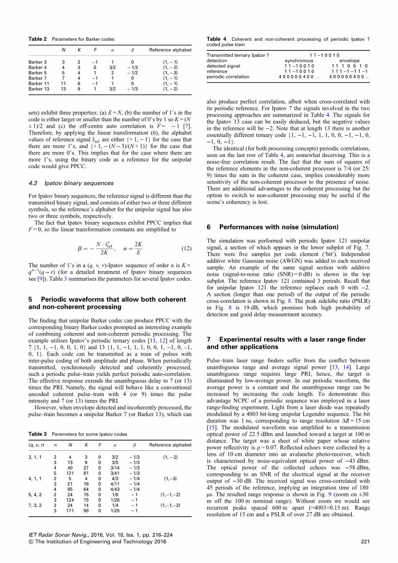
Table 2 Parameters for Barker codes
N K F α β Reference alphabet
Barker 3 3 2 −1 1 0 {1, − 1}Barker 4 4 3 0 3/2 − 1/3 {1, − 2}Barker 5 5 4 1 2 − 1/2 {1, − 3}Barker 7 7 4 −1 1 0 {1, − 1}Barker 11 11 6 −1 1 0 {1, − 1}Barker 13 13 9 1 3/2 − 1/3 {1, − 2}
Table 4 Coherent and non-coherent processing of periodic Ipatov 7coded pulse train
Transmitted ternary Ipatov 7 1 1 −1 0 0 1 0detection synchronous envelopedetected signal 1 1 −1 0 0 1 0 1 1 1 0 0 1 0reference 1 1 −1 0 0 1 0 1 1 1 −1 −1 1 −1periodic correlation 4 0 0 0 0 0 4 0 0 … 4 0 0 0 0 0 4 0 0 …
sets) exhibit three properties: (a) E =N, (b) the number of 1’s in thecode is either larger or smaller than the number of 0’s by 1 so K = (N± 1)/2 and (c) the off-centre auto correlation is F = − 1 [7].Therefore, by applying the linear transformation (6), the alphabetvalues of reference signal s̃ref are either {+ 1,− 1} for the case thatthere are more 1’s, and {+ 1,− (N− 3)/(N + 1)} for the case thatthere are more 0’s. This implies that for the case where there aremore 1’s, using the binary code as a reference for the unipolarcode would give PPCC.
4.3 Ipatov binary sequences
For Ipatov binary sequences, the reference signal is different than thetransmitted binary signal, and consists of either two or three differentsymbols, so the reference’s alphabet for the unipolar signal has alsotwo or three symbols, respectively.
The fact that Ipatov binary sequences exhibit PPCC implies thatF = 0, so the linear transformation constants are simplified to
b = − N · �s∗ref2K
, a = 2K
E(12)
The number of 1’s in a (q, v, r)-Ipatov sequence of order n is K =qn−1(q− r) (for a detailed treatment of Ipatov binary sequencessee [9]). Table 3 summarises the parameters for several Ipatov codes.
5 Periodic waveforms that allow both coherentand non-coherent processing
The finding that unipolar Barker codes can produce PPCC with thecorresponding binary Barker codes prompted an interesting exampleof combining coherent and non-coherent periodic processing. Theexample utilises Ipatov’s periodic ternary codes [11, 12] of length7 {1, 1, −1, 0, 0, 1, 0} and 13 {1, 1, −1, 1, 1, 0, 0, 1, −1, 0, –1,0, 1}. Each code can be transmitted as a train of pulses withinter-pulse coding of both amplitude and phase. When periodicallytransmitted, synchronously detected and coherently processed,such a periodic pulse–train yields perfect periodic auto-correlation.The effective response extends the unambiguous delay to 7 (or 13)times the PRI. Namely, the signal will behave like a conventionaluncoded coherent pulse–train with 4 (or 9) times the pulseintensity and 7 (or 13) times the PRI.
However, when envelope detected and incoherently processed, thepulse–train becomes a unipolar Barker 7 (or Barker 13), which can
Table 3 Parameters for some Ipatov codes
(q, v, r) n N K F α β Reference alphabet
3, 1, 1 2 4 3 0 3/2 − 1/3 {1, − 2}3 13 9 0 3/5 − 1/34 40 27 0 3/14 − 1/35 121 81 0 3/41 − 1/3
4, 1, 1 2 5 4 0 4/3 − 1/4 {1,−3}3 21 16 0 4/11 − 1/44 85 64 0 4/43 − 1/4
5, 4, 2 2 24 15 0 1/6 − 1 {1,−1,−2}3 124 75 0 1/26 − 1
7, 3, 2 2 24 14 0 1/4 − 1 {1,−1,−2}3 171 98 0 1/25 − 1
IET Radar Sonar Navig., 2016, Vol. 10, Iss. 1, pp. 216–224& The Institution of Engineering and Technology 2016
also produce perfect correlation, albeit when cross-correlated withits periodic reference. For Ipatov 7 the signals involved in the twoprocessing approaches are summarized in Table 4. The signals forthe Ipatov 13 case can be easily deduced, but the negative valuesin the reference will be −2. Note that at length 13 there is anotheressentially different ternary code {1, −1, −1, 1, 1, 0, 0, −1, −1, 0,−1, 0, −1}.
The identical (for both processing concepts) periodic correlations,seen on the last row of Table 4, are somewhat deceiving. This is anoise-free correlation result. The fact that the sum of squares ofthe reference elements in the non-coherent processor is 7/4 (or 25/9) times the sum in the coherent case, implies considerably moresensitivity of the non-coherent processor to the presence of noise.There are additional advantages to the coherent processing but theoption to switch to non-coherent processing may be useful if thescene’s coherency is lost.
6 Performances with noise (simulation)
The simulation was performed with periodic Ipatov 121 unipolarsignal, a section of which appears in the lower subplot of Fig. 7.There were five samples per code element (‘bit’). Independentadditive white Gaussian noise (AWGN) was added to each receivedsample. An example of the same signal section with additivenoise (signal-to-noise ratio (SNR) = 0 dB) is shown in the topsubplot. The reference Ipatov 121 contained 3 periods. Recall thatfor unipolar Ipatov 121 the reference replaces each 0 with −2.A section (longer than one period) of the output of the periodiccross-correlation is shown in Fig. 8. The peak sidelobe ratio (PSLR)in Fig. 8 is 19 dB, which promises both high probability ofdetection and good delay measurement accuracy.
7 Experimental results with a laser range finderand other applications
Pulse–train laser range finders suffer from the conflict betweenunambiguous range and average signal power [13, 14]. Largeunambiguous range requires large PRI; hence, the target isilluminated by low-average power. In our periodic waveform, theaverage power is a constant and the unambiguous range can beincreased by increasing the code length. To demonstrate thisadvantage NCPC of a periodic sequence was employed in a laserrange-finding experiment. Light from a laser diode was repeatedlymodulated by a 4003 bit-long unipolar Legendre sequence. The bitduration was 1 ns, corresponding to range resolution ΔR = 15 cm[15]. The modulated waveform was amplified to a transmissionoptical power of 22.5 dBm and launched toward a target at 100 mdistance. The target was a sheet of white paper whose relativepower reflectivity is ρ = 0.07. Reflected echoes were collected by alens of 10 cm diameter into an avalanche photo-receiver, whichis characterised by noise-equivalent optical power of −43 dBm.The optical power of the collected echoes was −58 dBm,corresponding to an SNR of the electrical signal at the receiveroutput of −30 dB. The received signal was cross-correlated with45 periods of the reference, implying an integration time of 180µs. The resulted range response is shown in Fig. 9 (zoom on ±30m off the 100 m nominal range). Without zoom we would seerecurrent peaks spaced 600 m apart (=4003×0.15 m). Rangeresolution of 15 cm and a PSLR of over 27 dB are obtained.
221
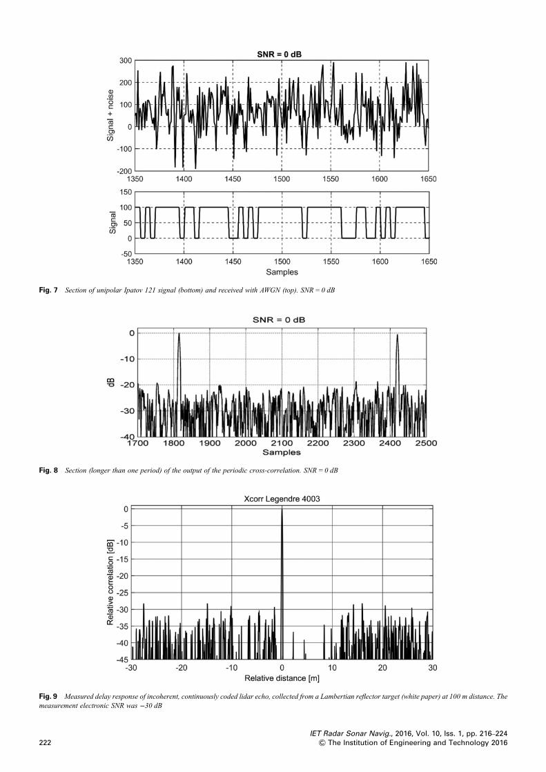
Fig. 7 Section of unipolar Ipatov 121 signal (bottom) and received with AWGN (top). SNR = 0 dB
Fig. 8 Section (longer than one period) of the output of the periodic cross-correlation. SNR = 0 dB
Fig. 9 Measured delay response of incoherent, continuously coded lidar echo, collected from a Lambertian reflector target (white paper) at 100 m distance. Themeasurement electronic SNR was −30 dB
IET Radar Sonar Navig., 2016, Vol. 10, Iss. 1, pp. 216–224222 & The Institution of Engineering and Technology 2016
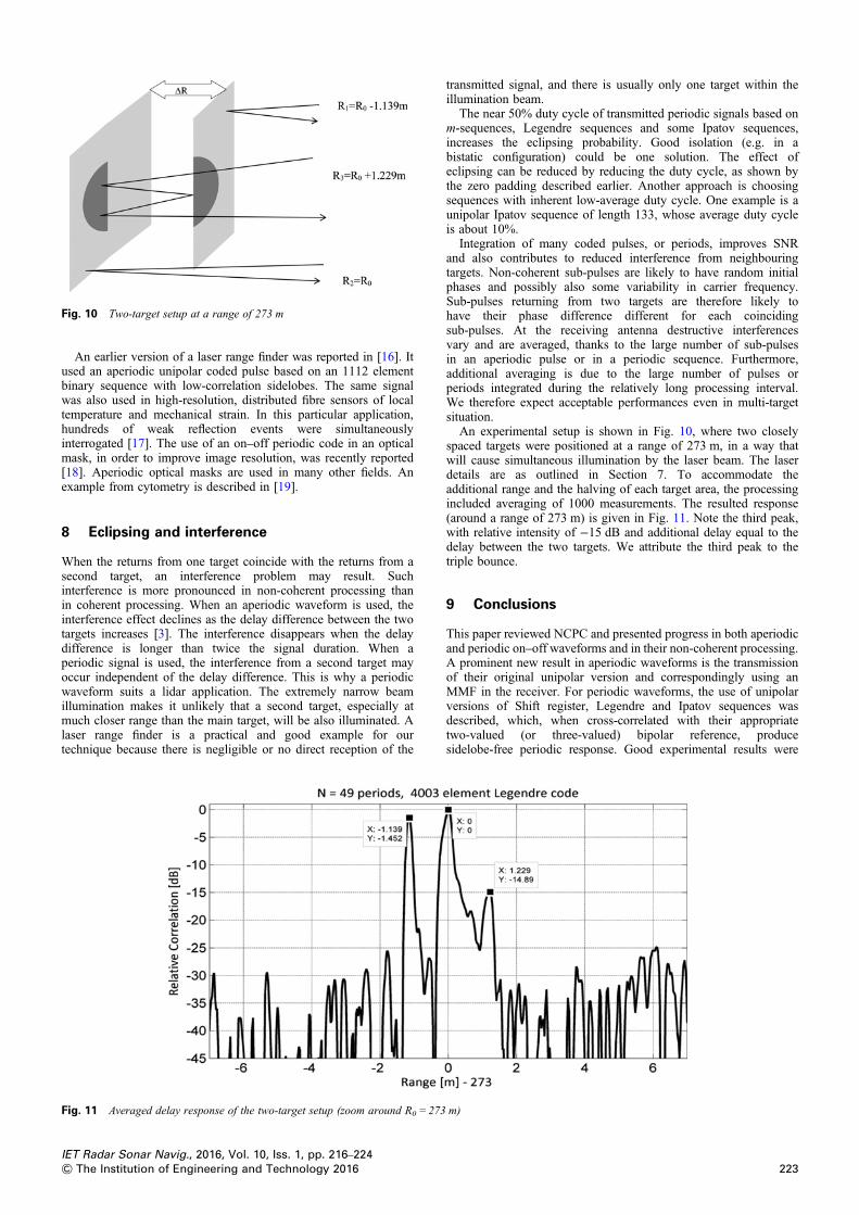
Fig. 10 Two-target setup at a range of 273 m
An earlier version of a laser range finder was reported in [16]. Itused an aperiodic unipolar coded pulse based on an 1112 elementbinary sequence with low-correlation sidelobes. The same signalwas also used in high-resolution, distributed fibre sensors of localtemperature and mechanical strain. In this particular application,hundreds of weak reflection events were simultaneouslyinterrogated [17]. The use of an on–off periodic code in an opticalmask, in order to improve image resolution, was recently reported[18]. Aperiodic optical masks are used in many other fields. Anexample from cytometry is described in [19].
8 Eclipsing and interference
When the returns from one target coincide with the returns from asecond target, an interference problem may result. Suchinterference is more pronounced in non-coherent processing thanin coherent processing. When an aperiodic waveform is used, theinterference effect declines as the delay difference between the twotargets increases [3]. The interference disappears when the delaydifference is longer than twice the signal duration. When aperiodic signal is used, the interference from a second target mayoccur independent of the delay difference. This is why a periodicwaveform suits a lidar application. The extremely narrow beamillumination makes it unlikely that a second target, especially atmuch closer range than the main target, will be also illuminated. Alaser range finder is a practical and good example for ourtechnique because there is negligible or no direct reception of the
Fig. 11 Averaged delay response of the two-target setup (zoom around R0 = 273
IET Radar Sonar Navig., 2016, Vol. 10, Iss. 1, pp. 216–224& The Institution of Engineering and Technology 2016
transmitted signal, and there is usually only one target within theillumination beam.
The near 50% duty cycle of transmitted periodic signals based onm-sequences, Legendre sequences and some Ipatov sequences,increases the eclipsing probability. Good isolation (e.g. in abistatic configuration) could be one solution. The effect ofeclipsing can be reduced by reducing the duty cycle, as shown bythe zero padding described earlier. Another approach is choosingsequences with inherent low-average duty cycle. One example is aunipolar Ipatov sequence of length 133, whose average duty cycleis about 10%.
Integration of many coded pulses, or periods, improves SNRand also contributes to reduced interference from neighbouringtargets. Non-coherent sub-pulses are likely to have random initialphases and possibly also some variability in carrier frequency.Sub-pulses returning from two targets are therefore likely tohave their phase difference different for each coincidingsub-pulses. At the receiving antenna destructive interferencesvary and are averaged, thanks to the large number of sub-pulsesin an aperiodic pulse or in a periodic sequence. Furthermore,additional averaging is due to the large number of pulses orperiods integrated during the relatively long processing interval.We therefore expect acceptable performances even in multi-targetsituation.
An experimental setup is shown in Fig. 10, where two closelyspaced targets were positioned at a range of 273 m, in a way thatwill cause simultaneous illumination by the laser beam. The laserdetails are as outlined in Section 7. To accommodate theadditional range and the halving of each target area, the processingincluded averaging of 1000 measurements. The resulted response(around a range of 273 m) is given in Fig. 11. Note the third peak,with relative intensity of −15 dB and additional delay equal to thedelay between the two targets. We attribute the third peak to thetriple bounce.
9 Conclusions
This paper reviewed NCPC and presented progress in both aperiodicand periodic on–off waveforms and in their non-coherent processing.A prominent new result in aperiodic waveforms is the transmissionof their original unipolar version and correspondingly using anMMF in the receiver. For periodic waveforms, the use of unipolarversions of Shift register, Legendre and Ipatov sequences wasdescribed, which, when cross-correlated with their appropriatetwo-valued (or three-valued) bipolar reference, producesidelobe-free periodic response. Good experimental results were
m)
223
shown, as obtained from a low-power lidar range finder that uses a4003 element on–off periodic code based on a Legendre sequence.The experimental results also showed good tolerance to atwo-target illumination scene. Periodic on–off waveforms areespecially suited to lidar range measurements because (a) laserslend themselves to very fast on–off keying and their non-coherentdetection is relatively simple to implement, (b) periodic waveformsavoid the pulse–train conflict between average power andunambiguous range and (c) due to the extremely narrow laserillumination, it is unlikely that clutter or close targets will beilluminated and eclipse the periodic waveform returning from thedesired distant target.
10 References
1 Levanon, N.: ‘Noncoherent pulse compression’, IEEE Trans. Aerosp. Electron.Syst., 2006, 42, (2), pp. 756–765
2 Levanon, N.: ‘Noncoherent radar pulse compression based on complementarysequences’, IEEE Trans. Aerosp. Electron. Syst., 2009, 45, (2), pp. 742–747
3 Peer, U., Levanon, N.: ‘Compression waveforms for non-coherent radar’. Proc.IEEE Radar Conf., Boston, MA, USA, April 2007
4 Levanon, N., Ben-Yaacov, E., Quartler, D.: ‘New waveform for magnetron marineradar – experimental results’, IET Radar Sonar Navig., 2012, 6, (5), pp. 314–321
5 Levanon, N.: ‘Creating sidelobe-free range zone around detected radar target’.2014 IEEE 28th Convention of Electrical and Electronics Engineers in Israel,Eylat, Israel, 3–5 December 2014. Available at http://www.ieeexplore.ieee.org/stamp/stamp.jsp?tp=&arnumber=7005837
6 Nazarathy, M., Newton, S.A., Giffard, R.F., et al.: ‘Real-time long rangecomplementary correlation optical time domain reflectometer’, J. LightwaveTechnol., 1989, 7, (1), pp. 24–37
224
7 Golomb, S.W.: ‘Shift Register Sequences’ (Aegean Park Press, Laguna Hills, CA,1982)
8 Farnett, E.C., Stevens, G.H.: ‘Pulse compression radar’, in Skolnik, M.I. (ED.):‘Radar handbook’ (McGraw-Hill, 1990, 2nd edn.), Ch. 10
9 Ipatov, V.P.: ‘Periodic discrete signals with optimal correlation properties’,Moscow, Radio I Svyaz, 1992, ISBN 5-256-00986-9, English Translation, TheUniversity of Adelaide, Australia
10 Levanon, N., Mozeson, E.: ‘Radar signals’ (Wiley, Hoboken, NJ, 2004), Sec. 6.511 Ipatov, V.P.: ‘Ternary sequences with ideal autocorrelation properties’, Radio Eng.
Electron. Phys., 1979, 24, pp. 75–7912 Ipatov, V.P.: ‘Spread spectrum and CDMA: principles and applications’ (Wiley,
Chichester, 2005), Sec. 6.11.313 Rieger, P., Ulrich, A.: ‘Resolving range ambiguities in high-repetition rate airborne
light detection and ranging applications’, J. Appl. Remote Sens., 2012, 6, (1),pp. 063552-1–063552-16
14 Rieger, P.: ‘Range ambiguity resolution technique applying pulse-positionmodulation in time-of-flight scanning lidar applications’, Opt. Eng., 2014, 53,(6), pp. 061614-1–061614-12
15 Arbel, N., Hirshbrand, L., Weiss, S., Levanon, N., Zadok, A.: ‘Continuous-wavelaser range finder based on incoherent compression of periodic sequences’. PaperSTh3O.2 in Conf. on Laser and Electro-Optics (CLEO) 2015, San-Jose, CA,May 2015
16 Kravitz, D., Grodensky, D., Levanon, N., Zadok, A.: ‘High-resolutionlow-sidelobe laser ranging based on incoherent pulse compression’, IEEEPhotonics Technol. Lett., 2012, 24, (23), pp. 2119–2121
17 London, N., Antman, Y., Cohen, R., Kimelfeld, N., Levanon, N., Zadok, A.:‘High-resolution long-range distributed Brillouin analysis using dual-layer phaseand amplitude coding’, Opt. Express, 2014, 22, (22), pp. 27144–27158
18 Ilovitsh, A., Preter, E., Levanon, N., Zalevsky, Z.: ‘Time multiplexing superresolution using a Barker-based array’, Opt. Lett., 2015, 40, (2), pp. 163–165
19 Sommer, C., Quint, S., Spang, P., Walther, T., Bassler, M.: ‘The equilibriumvelocity of spherical particles in rectangular microfluidic channels for sizemeasurements’, Lab Chip, 2014, 14, pp. 2319–2326
IET Radar Sonar Navig., 2016, Vol. 10, Iss. 1, pp. 216–224& The Institution of Engineering and Technology 2016