non-traditional machining · non-traditional machining 3.innovative geometric design of products...
TRANSCRIPT

Non-Traditional Machining
NON-TRADITIONAL MACHINING
INTRODUCTION
Non-traditional manufacturing processes is defined as a group of processes that remove
excess material by various techniques involving mechanical, thermal, electrical or
chemical energy or combinations of these energies but do not use a sharp cutting tools as
it needs to be used for traditional manufacturing processes.
Extremely hard and brittle materials are difficult to machine by traditional machining
processes such as turning, drilling, shaping and milling. Non traditional machining
processes, also called advanced manufacturing processes, are employed where traditional
machining processes are not feasible, satisfactory or economical due to special reasons as
outlined below.
Very hard fragile materials difficult to clamp for traditional machining
When the workpiece is too flexible or slender
When the shape of the part is too complex
Several types of non-traditional machining processes have been developed to meet extra
required machining conditions. When these processes are employed properly, they offer
many advantages over non-traditional machining processes. The common non-traditional
machining processes are described in this section.
Definition:
A machining process is called non-traditional if its material removal mechanism is
basically different than those in the traditional processes, i.e. a different form of energy
(other than the excessive forces exercised by a tool, which is in physical contact with the
work piece) is applied to remove the excess material from the work surface, or to separate
the workpiece into smaller parts.
1

Non-Traditional Machining
Non Traditional Machining (NTM) Processes are characterised as
follows:
• Material removal may occur with chip formation or even no chip formation may take place.
For example in AJM, chips are of microscopic size and in case of Electrochemical
machining material removal occurs due to electrochemical dissolution at atomic level
• In NTM, there may not be a physical tool present. For example in laser jet machining,
machining is carried out by laser beam. However in Electrochemical Machining there is a
physical tool that is very much required for machining
• In NTM, the tool need not be harder than the work piece material. For example, in EDM,
copper is used as the tool material to machine hardened steels.
• Mostly NTM processes do not necessarily use mechanical energy to provide material
removal. They use different energy domains to provide machining. For example, in USM,
AJM, WJM mechanical energy is used to machine material,
Need for development of Non Conventional Processes
The strength of steel alloys has increased five folds due to continuous R and D effort. In
aero-space requirement of High strength at elevated temperature with light weight led to
development and use of hard titanium alloys, nimonic alloys, and other HSTR alloys. The
ultimate tensile strength has been improved by as much as 20 times. Development of
cutting tools which has hardness of 80 to 85 HRC which cannot be machined
economically in
conventional methods led to development of non –traditional machining methods.
1.Technologically advanced industries like aerospace, nuclear power, ,wafer
fabrication, automobiles has ever increasing use of High –strength temperature resistant
(HSTR) alloys (having high strength to weight ratio) and other difficult to machine
materials like titanium, SST,nimonics, ceramics and semiconductors. It is no longer
possible to use conventional process to machine these alloys.
2.Production and processing parts of complicated shapes (in HSTR and other hard
to machine alloys) is difficult , time consuming an uneconomical by conventional
methods of machining
2

Non-Traditional Machining
3.Innovative geometric design of products and components made of new exotic
materials with desired tolerance , surface finish cannot be produced economically by
conventional machining.
4.The following examples are provided where NTM processes are preferred over
the conventional machining process:
♦ Intricate shaped blind hole – e.g. square hole of 15 mmx15 mm with a depth of 30 mm
with a tolerance of 100 microns
♦ Difficult to machine material – e.g. Inconel, Ti-alloys or carbides, Ceramics,
composites , HSTR alloys, satellites etc.,
♦ Low Stress Grinding – Electrochemical Grinding is preferred as compared to
conventional grinding
♦ Deep hole with small hole diameter – e.g. φ 1.5 mm hole with l/d = 20
♦ Machining of composites
Differences between Conventional and Non conventional
machining processes.
Sl Conventional Process Non Conventional Process
No.
1. The cutting tool and work piece are There is no physical contact between
always in physical contact with the tool and work piece, In some non
relative motion with each other, traditional process tool wear exists.
which results in friction and tool
wear.
2. Material removal rate is limited by NTM can machine difficult to cut and
mechanical properties of work hard to cut materials like
material. titanium,ceramics,nimonics,
SST,composites,semiconducting
materials
3
Non-Traditional Machining
3. Relative motion between the tool Many NTM are capable of producing
and work is typically rotary or complex 3D shapes and cavities
reciprocating. Thus the shape of
work is limited to circular or flat
shapes. In spite of CNC systems,
production of 3D surfaces is still a
difficult task.
4. Machining of small cavities , slits , Machining of small cavities, slits and
blind holes or through holes are Production of non-circular, micro sized,
difficult large aspect ratio, shall entry angle
holes are easy using NTM
5. Use relative simple and inexpensive Non traditional processes requires
machinery and readily available expensive tools and equipment as well
cutting tools as skilled labour, which increase the
production cost significantly
6. Capital cost and maintenance cost is Capital cost and maintenance cost is
low high
7. Traditional processes are well Mechanics of Material removal of Some
established and physics of process of NTM process are still under research
is well understood
8. Conventional process mostly uses Most NTM uses energy in direct form
mechanical energy For example : laser, Electron beam in
its direct forms are used in LBM and
EBM respectively
9. Surface finish and tolerances are High surface finish(up to 0.1 micron)
limited by machining inaccuracies and tolerances (25 Microns)can be
achieved
10. High metal removal rate. Low material removal rate.
4

Non-Traditional Machining
SELECTION OF PROCESS:
The correct selection of the non-traditional machining methods must be based on the
following aspects.
i) Physical parameters of the process
ii) Shape to be machined
iii) Process capability
iv) Economics of the processes
Physical parameter of the process:
The physical parameters of the different NTM are given in the Table 1.0 which indicates
that PAM and ECM require high power for fast machining. EBM and LBM require high
voltages and require careful handling of equipment. EDM and USM require medium
power . EBM can be used in vacuum and PAM uses oxygen and hydrogen gas.
Shapes cutting capability
The different shapes can be machined by NTM. EBM and LBM are used for micro
drilling and cutting. USM and EDM are useful for cavity sinking and standard hole
drilling. ECM is useful for fine hole drilling and contour machining. PAM can be used for
cutting and AJM is useful for shallow pocketing
Process capability
The process capability of NTM is given in Table 2.0 EDM which achieves higher
accuracy has the lowest specific power requirement. ECM can machine faster and has a
low thermal surface damage depth. USM and AJM have very material removal rates
combined with high tool wear and are used non metal cutting. LBM and EBM are, due to
their high penetration depth can be used for micro drilling, sheet cutting and welding.
CHM is used for manufacture of PCM and other shallow components.
5

Non-Traditional Machining
PHYSICAL PARAMETER OF THE PROCESS:
Classification of NTM processes is carried out depending on the nature of energy
used for material removal. The broad classification is given as follows:
• Mechanical Processes⎯ Abrasive Jet Machining (AJM)⎯ Ultrasonic Machining (USM)⎯ Water Jet Machining (WJM)
• Electrochemical Processes⎯ Electrochemical Machining (ECM)⎯ Electro Chemical Grinding (ECG)⎯ Electro Jet Drilling (EJD)
• Electro-Thermal Processes⎯ Electro-discharge machining (EDM)⎯ Laser Jet Machining (LJM)⎯ Electron Beam Machining (EBM)
• Chemical Processes⎯ Chemical Milling (CHM)⎯ Photochemical Milling (PCM)
6

Non-Traditional Machining
7

Non-Traditional Machining
ULTRASONIC MACHINING (USM)
INTRODUCTION
USM is mechanical material removal process or an abrasive process used to erode holes
or cavities on hard or brittle workpiece by using shaped tools, high frequency mechanical
motion and an abrasive slurry. USM offers a solution to the expanding need for
machining brittle materials such as single crystals, glasses and polycrystalline ceramics,
and increasing complex operations to provide intricate shapes and workpiece profiles. It
is therefore used extensively in machining hard and brittle materials that are difficult to
machine by traditional manufacturing processes.
Ultrasonic Machining is a non-traditional process, in which abrasives contained in a
slurry are driven against the work by a tool oscillating at low amplitude (25-100 μm) and
high frequency (15-30 KHz):
The process was first developed in 1950s and was originally used for finishing EDM
surfaces.
The basic process is that a ductile and tough tool is pushed against the work with a
constant force. A constant stream of abrasive slurry passes between the tool and the work
(gap is 25-40 μm) to provide abrasives and carry away chips. The majority of the cutting
action comes from an ultrasonic (cyclic) force applied.
The basic components to the cutting action are believed to be,
brittle fracture caused by impact of abrasive grains due to the tool vibration;
cavitation induced erosion;
chemical erosion caused by slurry.
8

Non-Traditional Machining
USM working principle
• Material removal primarily occurs due to the indentation of the hard abrasive grits
on the brittle work material.
• Other than this brittle failure of the work material due to indentation some
material removal may occur due to free flowing impact of the abrasives against
the work material and related solid-solid impact erosion,
• Tool’s vibration – indentation by the abrasive grits.
• During indentation, due to Hertzian contact stresses, cracks would develop just
below the contact site, then as indentation progresses the cracks would propagate
due to increase in stress and ultimately lead to brittle fracture of the work material
9
Non-Traditional Machining
under each individual interaction site between the abrasive grits and the
workpiece.
• The tool material should be such that indentation by the abrasive grits does not
lead to brittle failure.
• Thus the tools are made of tough, strong and ductile materials like steel, stainless
steel and other ductile metallic alloys.
USM Machine
USM Equipment
10
Non-Traditional Machining
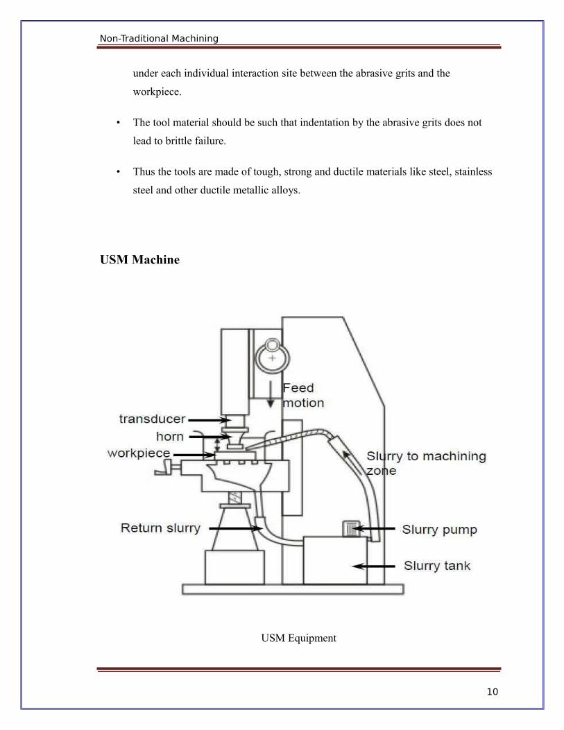
The basic mechanical structure of an USM is very similar to a drill press.
However, it has additional features to carry out USM of brittle work material. The work
piece is mounted on a vice, which can be located at the desired position under the tool
using a 2 axis table. The table can further be lowered or raised to accommodate work of
different thickness.
The typical elements of an USM are
Slurry delivery and return system
Feed mechanism to provide a downward feed force on the tool during machining
The transducer, which generates the ultrasonic vibration
The horn or concentrator, which mechanically amplifies the vibration to the
required amplitude of 15 – 50 μm and accommodates the tool at its tip.
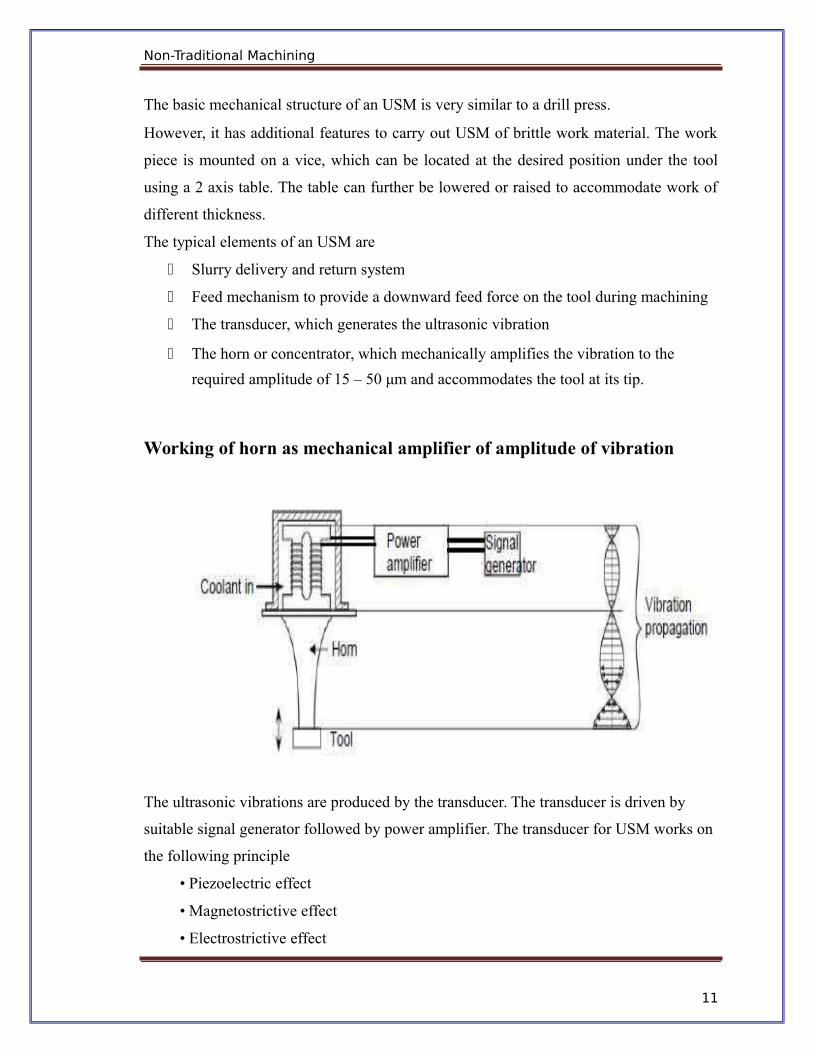
Working of horn as mechanical amplifier of amplitude of vibration
The ultrasonic vibrations are produced by the transducer. The transducer is driven by
suitable signal generator followed by power amplifier. The transducer for USM works on
the following principle
• Piezoelectric effect
• Magnetostrictive effect
• Electrostrictive effect
11
Non-Traditional Machining
Magnetostrictive transducers are most popular and robust amongst all. Figure shows a
typical magnetostrictive transducer along with horn. The horn or concentrator is a wave
guide, which amplifies and concentrates the vibration to the tool from the transducer.
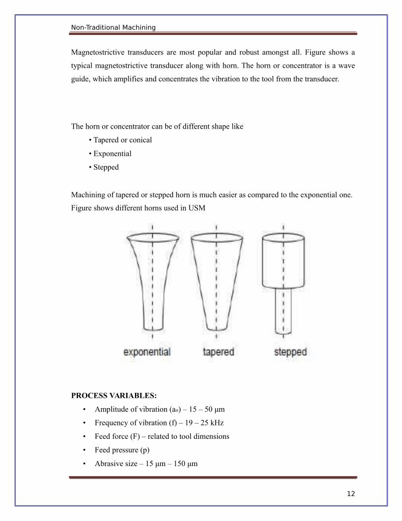
The horn or concentrator can be of different shape like
• Tapered or conical
• Exponential
• Stepped
Machining of tapered or stepped horn is much easier as compared to the exponential one.
Figure shows different horns used in USM
PROCESS VARIABLES:
• Amplitude of vibration (ao) – 15 – 50 μm
• Frequency of vibration (f) – 19 – 25 kHz
• Feed force (F) – related to tool dimensions
• Feed pressure (p)
• Abrasive size – 15 μm – 150 μm
12

Non-Traditional Machining
• Abrasive material – Al2O3
- SiC
- B4C
- Boronsilicarbide
- Diamond
Flow strength of work material
Flow strength of the tool material
Contact area of the tool – A
Volume concentration of abrasive in water slurry – C
Applications of USM
• Used for machining hard and brittle metallic alloys, semiconductors, glass,
ceramics, carbides etc.
• Used for machining round, square, irregular shaped holes and surface impressions.
• Machining, wire drawing, punching or small blanking dies.
Figure: A non-round hole made by USM
Advantage of USM
USM process is a non-thermal, non-chemical, creates no changes in the microstructures,
chemical or physical properties of the workpiece and offers virtually stress free machined
surfaces.
13
Non-Traditional Machining
The main advantages are;
· Any materials can be machined regardless of their electrical conductivity
· Especially suitable for machining of brittle materials
· Machined parts by USM possess better surface finish and higher structural integrity.
· USM does not produce thermal, electrical and chemical abnormal surface
Some disadvantages of USM
· USM has higher power consumption and lower material-removal rates than traditional
fabrication processes.
· Tool wears fast in USM.
· Machining area and depth is restraint in USM.
14
Non-Traditional Machining
ABRASIVE JET MACHINING (AJM)
INTRODUCTION
Abrasive water jet cutting is an extended version of water jet cutting; in which the water
jet contains abrasive particles such as silicon carbide or aluminium oxide in order to
increase the material removal rate above that of water jet machining. Almost any type of
material ranging from hard brittle materials such as ceramics, metals and glass to
extremely soft materials such as foam and rubbers can be cut by abrasive water jet
cutting. The narrow cutting stream and computer controlled movement enables this
process to produce parts accurately and efficiently. This machining process is especially
ideal for cutting materials that cannot be cut by laser or thermal cut. Metallic, non-
metallic and advanced composite materials of various thicknesses can be cut by this
process. This process is particularly suitable for heat sensitive materials that cannot be
machined by processes that produce heat while machining.
Working principle
15
Non-Traditional Machining
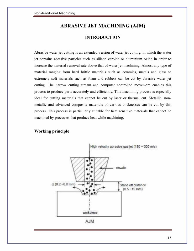
In Abrasive Jet Machining (AJM), abrasive particles are made to impinge on the work
material at a high velocity. The jet of abrasive particles is carried by carrier gas or air. The
high velocity stream of abrasive is generated by converting the pressure energy of the
carrier gas or air to its kinetic energy and hence high velocity jet. The nozzle directs the
abrasive jet in a controlled manner onto the work material, so that the distance between
the nozzle and the work piece and the impingement angle can be set desirably. The high
velocity abrasive particles remove the material by micro-cutting action as well as brittle
fracture of the work material.
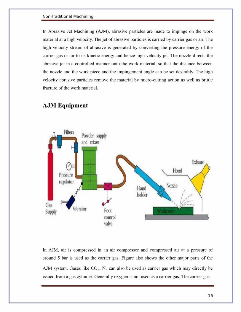
AJM Equipment
In AJM, air is compressed in an air compressor and compressed air at a pressure of
around 5 bar is used as the carrier gas. Figure also shows the other major parts of the
AJM system. Gases like CO2, N2 can also be used as carrier gas which may directly be
issued from a gas cylinder. Generally oxygen is not used as a carrier gas. The carrier gas
16
Non-Traditional Machining
is first passed through a pressure regulator to obtain the desired working pressure. To
remove any oil vapour or particulate contaminant the same is passed through a series of
filters. Then the carrier gas enters a closed chamber known as the mixing chamber. The
abrasive particles enter the chamber from a hopper through a metallic sieve. The sieve is
constantly vibrated by an electromagnetic shaker. The mass flow rate of abrasive (15
gm/min) entering the chamber depends on the amplitude of vibration of the sieve and its
frequency. The abrasive particles are then carried by the carrier gas to the machining
chamber via an electro-magnetic on-off valve. The machining enclosure is essential to
contain the abrasive and machined particles in a safe and eco-friendly manner. The
machining is carried out as high velocity (200 m/s) abrasive particles are issued from the
nozzle onto a work piece traversing under the jet.
Process Parameters and Machining Characteristics.
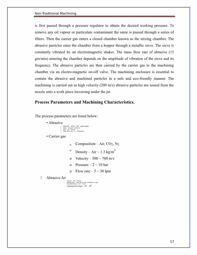
The process parameters are listed below:
• Abrasive⎯ Material – Al2O3 / SiC / glass beads⎯ Shape – irregular / spherical⎯ Size – 10 ~ 50 μm⎯ Mass flow rate – 2 ~ 20 gm/min
• Carrier gas
o Composition – Air, CO2, N2
o Density – Air ~ 1.3 kg/m3
o Velocity – 500 ~ 700 m/s
o Pressure – 2 ~ 10 bar
o Flow rate – 5 ~ 30 lpm
Abrasive Jet⎯ Velocity – 100 ~ 300 m/s⎯ Mixing ratio – mass flow ratio of abrasive to gas⎯ Stand-off distance – 0.5 ~ 5 mm⎯ Impingement Angle – 600 ~ 900
17
Non-Traditional Machining
• Nozzle⎯ Material – WC / sapphire⎯ Diameter – (Internal) 0.2 ~ 0.8 mm⎯ Life – 10 ~ 300 hours
The important machining characteristics in AJM are
• The material removal rate (MRR) mm3/min or gm/min
• The machining accuracy
• The life of the nozzle
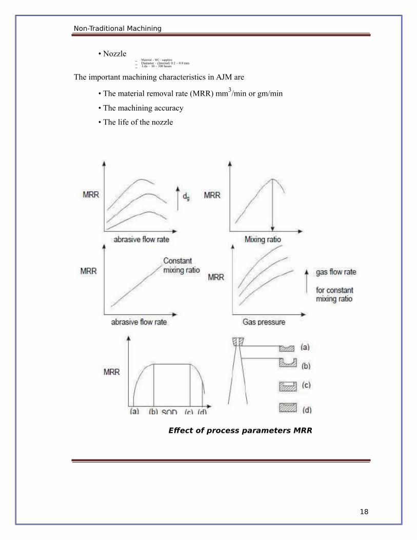
Effect of process parameters MRR
18

Non-Traditional Machining
Parameters of Abrasive Jet Maching (AJM) are factors that influence its Metal Removal
Rate (MRR). In a machining process, Metal Removal Rate (MRR) is the volume of metal
removed from a given work piece in unit time. The following are some of the important
process parameters of abrasive jet machining:
1. Abrasive mass flow rate
2. Nozzle tip distance
3. Gas Pressure
4. Velocity of abrasive particles
5. Mixing ratio
6. Abrasive grain size
Abrasive mass flow rate:
Mass flow rate of the abrasive particles is a major process parameter that influences the
metal removal rate in abrasive jet machining.
In AJM, mass flow rate of the gas (or air) in abrasive jet is inversely proportional to the
mass flow rate of the abrasive particles.
Due to this fact, when continuously increasing the abrasive mass flow rate, Metal
Removal Rate (MRR) first increases to an optimum value (because of increase in number
of abrasive particles hitting the work piece) and then decreases.
However, if the mixing ratio is kept constant, Metal Removal Rate (MRR) uniformly
increases with increase in abrasive mass flow rate.
Nozzle tip distance:
Nozzle Tip Distance (NTD) is the gap provided between the nozzle tip and the work
piece.
Up to a certain limit, Metal Removal Rate (MRR) increases with increase in nozzle tip
distance. After that limit, MRR remains constant to some extent and then decreases.
19
Non-Traditional Machining
In addition to metal removal rate, nozzle tip distance influences the shape and diameter of
cut.
For optimal performance, a nozzle tip distance of 0.25 to 0.75 mm is provided.
Gas pressure:
Air or gas pressure has a direct impact on metal removal rate.
In abrasive jet machining, metal removal rate is directly proportional to air or gas
pressure.
Velocity of abrasive particles:
Whenever the velocity of abrasive particles is increased, the speed at which the abrasive
particles hit the work piece is increased. Because of this reason, in abrasive jet
machining, metal removal rate increases with increase in velocity of abrasive particles.
Mixing ratio:
Mixing ratio is a ratio that determines the quality of the air-abrasive mixture in Abrasive
Jet Machining (AJM).
It is the ratio between the mass flow rate of abrasive particles and the mass flow rate of
air (or gas).
When mixing ratio is increased continuously, metal removal rate first increases to some
extent and then decreases.
Abrasive grain size:
Size of the abrasive particle determines the speed at which metal is removed.
If smooth and fine surface finish is to be obtained, abrasive particle with small grain size
is used.
If metal has to be removed rapidly, abrasive particle with large grain size is used.
20
Non-Traditional Machining
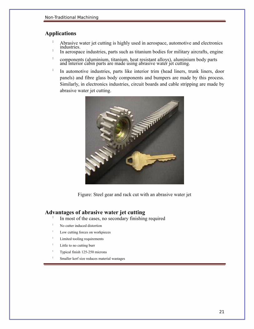
Applications Abrasive water jet cutting is highly used in aerospace, automotive and electronics
industries. In aerospace industries, parts such as titanium bodies for military aircrafts, engine components (aluminium, titanium, heat resistant alloys), aluminium body parts
and interior cabin parts are made using abrasive water jet cutting. In automotive industries, parts like interior trim (head liners, trunk liners, door
panels) and fibre glass body components and bumpers are made by this process.Similarly, in electronics industries, circuit boards and cable stripping are made byabrasive water jet cutting.
Figure: Steel gear and rack cut with an abrasive water jet
Advantages of abrasive water jet cutting In most of the cases, no secondary finishing required No cutter induced distortion Low cutting forces on workpieces Limited tooling requirements Little to no cutting burr Typical finish 125-250 microns Smaller kerf size reduces material wastages
21

Non-Traditional Machining
No heat affected zone Localises structural changes No cutter induced metal contamination Eliminates thermal distortion No slag or cutting dross Precise, multi plane cutting of contours, shapes, and bevels of any angle.
Limitations of abrasive water jet cutting
Cannot drill flat bottom
Cannot cut materials that degrades quickly with moisture
Surface finish degrades at higher cut speeds which are frequently used for rough
cutting.
The major disadvantages of abrasive water jet cutting are high capital cost and
high
noise levels during operation.
22
Non-Traditional Machining
WATER JET MACHINING (WJM)
INTRODUCTION
Abrasive water jet cutting is an extended version of water jet cutting; in which the water
jet contains abrasive particles such as silicon carbide or aluminium oxide in order to
increase the material removal rate above that of water jet machining. Almost any type of
material ranging from hard brittle materials such as ceramics, metals and glass to
extremely soft materials such as foam and rubbers can be cut by abrasive water jet
cutting. The narrow cutting stream and computer controlled movement enables this
process to produce parts accurately and efficiently. This machining process is especially
ideal for cutting materials that cannot be cut by laser or thermal cut. Metallic, non-
metallic and advanced composite materials of various thicknesses can be cut by this
process. This process is particularly suitable for heat sensitive materials that cannot be
machined by processes that produce heat while machining.
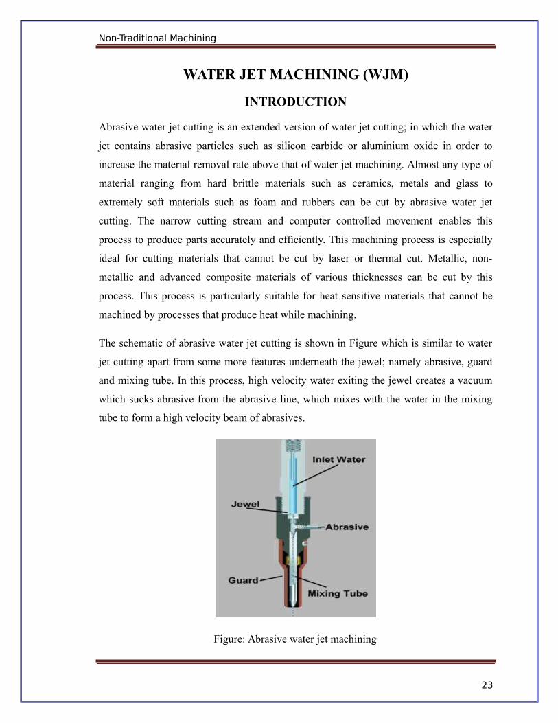
The schematic of abrasive water jet cutting is shown in Figure which is similar to water
jet cutting apart from some more features underneath the jewel; namely abrasive, guard
and mixing tube. In this process, high velocity water exiting the jewel creates a vacuum
which sucks abrasive from the abrasive line, which mixes with the water in the mixing
tube to form a high velocity beam of abrasives.
Figure: Abrasive water jet machining
23

Non-Traditional Machining
Applications
Abrasive water jet cutting is highly used in aerospace, automotive and electronics
industries. In aerospace industries, parts such as titanium bodies for military aircrafts,
engine components (aluminium, titanium, heat resistant alloys), aluminium body parts
and interior cabin parts are made using abrasive water jet cutting.
In automotive industries, parts like interior trim (head liners, trunk liners, door panels)
and fibre glass body components and bumpers are made by this process. Similarly, in
electronics industries, circuit boards and cable stripping are made by abrasive water jet
cutting.
Advantages of abrasive water jet cutting
In most of the cases, no secondary finishing required
No cutter induced distortion
Low cutting forces on workpieces
Limited tooling requirements
Little to no cutting burr
Typical finish 125-250 microns
Smaller kerf size reduces material wastages
No heat affected zone
Localises structural changes
No cutter induced metal contamination
Eliminates thermal distortion
No slag or cutting dross
Precise, multi plane cutting of contours, shapes, and bevels of any angle.
24
Non-Traditional Machining
Limitations of abrasive water jet cutting
Cannot drill flat bottom
Cannot cut materials that degrades quickly with moisture
Surface finish degrades at higher cut speeds which are frequently used for
rough cutting.
The major disadvantages of abrasive water jet cutting are high capital cost
and high noise levels during operation.
25

26
Non-Traditional Machining
ELECTROCHEMICAL MACHINING (ECM)
INTRODUCTION
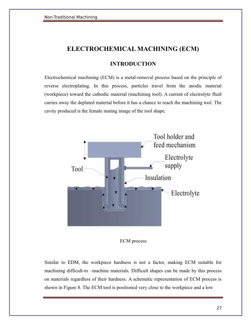
Electrochemical machining (ECM) is a metal-removal process based on the principle of
reverse electroplating. In this process, particles travel from the anodic material
(workpiece) toward the cathodic material (machining tool). A current of electrolyte fluid
carries away the deplated material before it has a chance to reach the machining tool. The
cavity produced is the female mating image of the tool shape.
ECM process
Similar to EDM, the workpiece hardness is not a factor, making ECM suitable for
machining difficult-to –machine materials. Difficult shapes can be made by this process
on materials regardless of their hardness. A schematic representation of ECM process is
shown in Figure 8. The ECM tool is positioned very close to the workpiece and a low
27

Page 26
28
Non-Traditional Machining
voltage, high amperage DC current is passed between the workpiece and electrode. Some
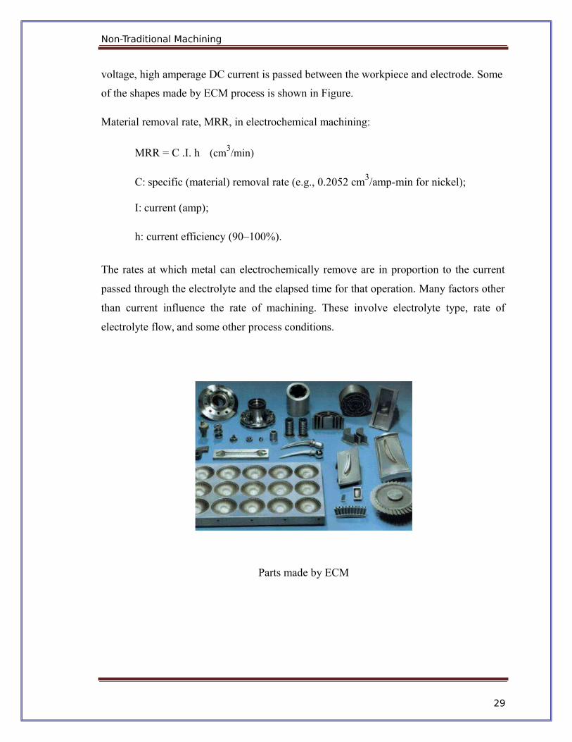
of the shapes made by ECM process is shown in Figure.
Material removal rate, MRR, in electrochemical machining:
MRR = C .I. h (cm3/min)
C: specific (material) removal rate (e.g., 0.2052 cm3/amp-min for nickel);
I: current (amp);
h: current efficiency (90–100%).
The rates at which metal can electrochemically remove are in proportion to the current
passed through the electrolyte and the elapsed time for that operation. Many factors other
than current influence the rate of machining. These involve electrolyte type, rate of
electrolyte flow, and some other process conditions.
Parts made by ECM
29
Non-Traditional Machining
Advantages of ECM
The components are not subject to either thermal or mechanical stress.
No tool wear during ECM process.
Fragile parts can be machined easily as there is no stress involved.
ECM deburring can debur difficult to access areas of parts.
High surface finish (up to 25 µm in) can be achieved by ECM process.
Complex geometrical shapes in high-strength materials particularly in the
aerospace industry for the mass production of turbine blades, jet-engine parts and
nozzles can be machined repeatedly and accurately.
Deep holes can be made by this process.
Limitations of ECM
ECM is not suitable to produce sharp square corners or flat bottoms because of
the tendency for the electrolyte to erode away sharp profiles.
ECM can be applied to most metals but, due to the high equipment costs, is
usually used primarily for highly specialised applications.
Material removal rate, MRR, in electrochemical machining:
MRR = C .I. h (cm3/min)
C: specific (material) removal rate (e.g., 0.2052 cm3/amp-min for nickel);
I: current (amp);
h: current efficiency (90–100%).
The rates at which metal can electrochemically remove are in proportion to the current
passed through the electrolyte and the elapsed time for that operation. Many factors other
than current influence the rate of machining. These involve electrolyte type, rate of
electrolyte flow, and some other process conditions.
30
Non-Traditional Machining
CHEMICAL MACHINING (CHM)
INTRODUCTION
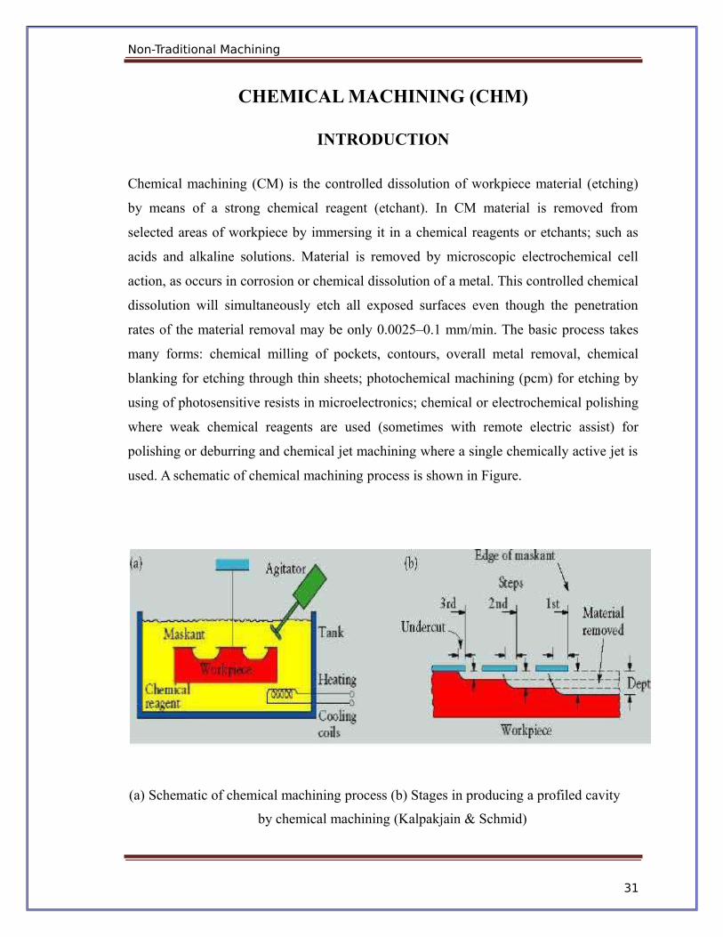
Chemical machining (CM) is the controlled dissolution of workpiece material (etching)
by means of a strong chemical reagent (etchant). In CM material is removed from
selected areas of workpiece by immersing it in a chemical reagents or etchants; such as
acids and alkaline solutions. Material is removed by microscopic electrochemical cell
action, as occurs in corrosion or chemical dissolution of a metal. This controlled chemical
dissolution will simultaneously etch all exposed surfaces even though the penetration
rates of the material removal may be only 0.0025–0.1 mm/min. The basic process takes
many forms: chemical milling of pockets, contours, overall metal removal, chemical
blanking for etching through thin sheets; photochemical machining (pcm) for etching by
using of photosensitive resists in microelectronics; chemical or electrochemical polishing
where weak chemical reagents are used (sometimes with remote electric assist) for
polishing or deburring and chemical jet machining where a single chemically active jet is
used. A schematic of chemical machining process is shown in Figure.
(a) Schematic of chemical machining process (b) Stages in producing a profiled cavity
by chemical machining (Kalpakjain & Schmid)
31

Non-Traditional Machining
CHEMICAL MILLING
In chemical milling, shallow cavities are produced on plates, sheets, forgings and
extrusions. The two key materials used in chemical milling process are etchant and
maskant. Etchants are acid or alkaline solutions maintained within controlled ranges of
chemical composition and temperature. Maskants are specially designed elastomeric
products that are hand strippable and chemically resistant to the harsh etchants.
Steps in chemical milling
Residual stress relieving: If the part to be machined has residual stresses from the
previous processing, these stresses first should be relieved in order to prevent
warping after chemical milling.
Preparing: The surfaces are degreased and cleaned thoroughly to ensure both good
adhesion of the masking material and the uniform material removal.
Masking: Masking material is applied (coating or protecting areas not to be
etched).
Etching: The exposed surfaces are machined chemically with etchants.
Demasking: After machining, the parts should be washed thoroughly to prevent
further reactions with or exposure to any etchant residues. Then the rest of the
masking material is removed and the part is cleaned and inspected.
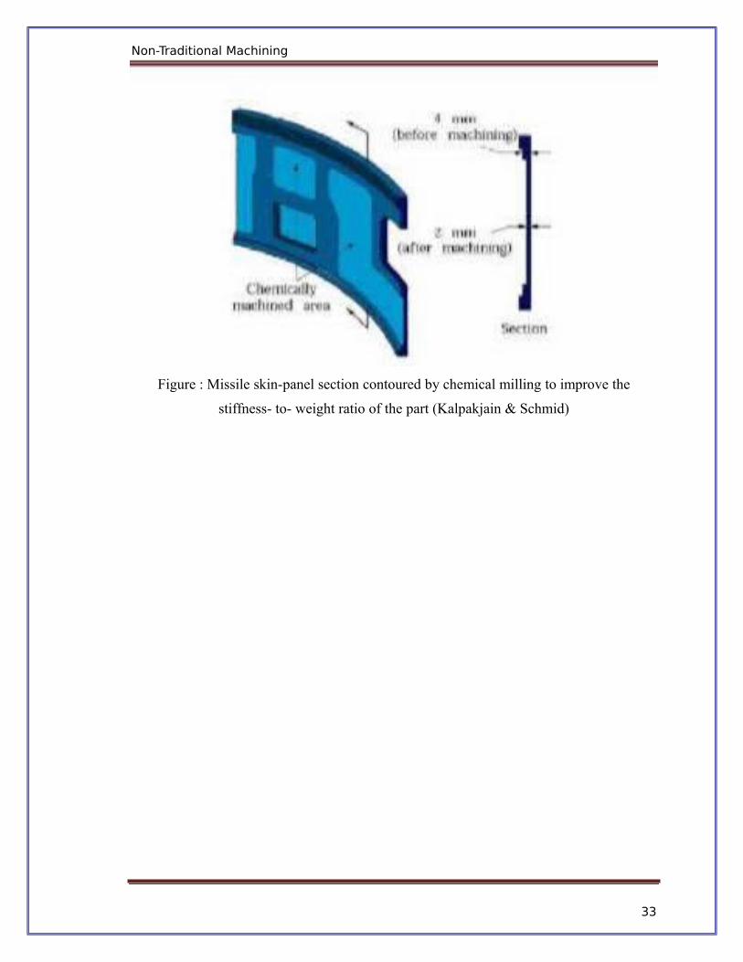
Applications:
Chemical milling is used in the aerospace industry to remove shallow layers of material
from large aircraft components missile skin panels (Figure ), extruded parts for airframes.
32
Non-Traditional Machining
Figure : Missile skin-panel section contoured by chemical milling to improve the
stiffness- to- weight ratio of the part (Kalpakjain & Schmid)
33

Non-Traditional Machining
ELECTRICAL DISCHARGE MACHINING (EDM)
INTRODUCTION
Electrical discharge machining (EDM) is one of the most widely used non-traditional
machining processes. The main attraction of EDM over traditional machining processes
such as metal cutting using different tools and grinding is that this technique utilises
thermoelectric process to erode undesired materials from the workpiece by a series of
discrete electrical sparks between the workpiece and the electrode. A picture of EDM
machine in operation is shown in Figure.
Figure : Electrical discharge machine
The traditional machining processes rely on harder tool or abrasive material to remove the
softer material whereas non-traditional machining processes such as EDM uses electrical
spark or thermal energy to erode unwanted material in order to create desired shape. So,
the hardness of the material is no longer a dominating factor for EDM process. A
schematic of an EDM process is shown in Figure 2, where the tool and the workpiece are
immersed in a dielectric fluid.
34

Non-Traditional Machining
Working principle of EDM
As shown in Figure 1, at the beginning of EDM operation, a high voltage is applied
across the narrow gap between the electrode and the workpiece. This high voltage induces
an electric field in the insulating dielectric that is present in narrow gap between electrode
and workpiece. This cause conducting particles suspended in the dielectric to concentrate
at the points of strongest electrical field. When the potential difference between the
electrode and the workpiece is sufficiently high, the dielectric breaks down and a transient
spark discharges through the dielectric fluid, removing small amount of material from the
workpiece surface. The volume of the material removed per spark discharge is typically
in the range of 10-6 to 10-6 mm3.
The material removal rate, MRR, in EDM is calculated by the following foumula:
MRR = 40 I / Tm 1.23 (cm3/min)
Where, I is the current amp,
Tm is the melting temperature of workpiece in 0C
Figure: Schematic of EDM process
35
Non-Traditional Machining
EDM removes material by discharging an electrical current, normally stored in a
capacitor bank, across a small gap between the tool (cathode) and the workpiece (anode)
typically in the order of 50 volts/10amps.
Dielectric fluids
Dielectric fluids used in EDM process are hydrocarbon oils, kerosene and deionised
water. The functions of the dielectric fluid are to:
Act as an insulator between the tool and the workpiece.
Act as coolant.
Act as a flushing medium for the removal of the chips.
The electrodes for EDM process usually are made of graphite, brass, copper and copper-
tungsten alloys.
Design considerations for EDM process are as follows:
Deep slots and narrow openings should be avoided.
The surface smoothness value should not be specified too fine.
Rough cut should be done by other machining process. Only finishing operation
should be done in this process as MRR for this process is low.
Wire EDM
EDM, primarily, exists commercially in the form of die-sinking machines and wire-
cutting machines (Wire EDM). The concept of wire EDM is shown in Figure 4. In this
process, a slowly moving wire travels along a prescribed path and removes material from
the workpiece. Wire EDM uses electro-thermal mechanisms to cut electrically conductive
materials. The material is removed by a series of discrete discharges between the wire
electrode and the workpiece in the presence of dieelectirc fluid, which creates a path for
each discharge as the fluid becomes ionized in the gap. The area where discharge takes
36

Non-Traditional Machining
place is heated to extremely high temperature, so that the surface is melted and removed.
The removed particles are flushed away by the flowing dielectric fluids.
The wire EDM process can cut intricate components for the electric and aerospace
industries. This non-traditional machining process is widely used to pattern tool steel for
die manufacturing.
Wire erosion of an extrusion die
The wires for wire EDM is made of brass, copper, tungsten, molybdenum. Zinc or brass
coated wires are also used extensively in this process. The wire used in this process
should posses high tensile strength and good electrical conductivity. Wire EDM can also
employ to cut cylindrical objects with high precision. The sparked eroded extrusion dies
are presented in Figure.
37

Non-Traditional Machining
.
Sparked eroded extrusion dies
This process is usually used in conjunction with CNC and will only work when a part is
to be cut completely through. The melting temperature of the parts to be machined is an
important parameter for this process rather than strength or hardness. The surface quality
and MRR of the machined surface by wire EDM will depend on different machining
parameters such as applied peak current, and wire materials.
Application of EDM
The EDM process has the ability to machine hard, difficult-to-machine materials. Parts
with complex, precise and irregular shapes for forging, press tools, extrusion dies,
difficult internal shapes for aerospace and medical applications can be made by EDM
process. Some of the shapes made by EDM process are shown in Figure.
38

Non-Traditional Machining
Figure: Difficult internal parts made by EDM process
Advantages of EDM
The main advantages of DM are:
By this process, materials of any hardness can be machined;
No burrs are left in machined surface;
One of the main advantages of this process is that thin and fragile/brittle
components can be machined without distortion;
Complex internal shapes can be machined
Limitations of EDM
The main limitations of this process are:
This process can only be employed in electrically conductive materials;
Material removal rate is low and the process overall is slow compared to
conventional machining processes;
Unwanted erosion and over cutting of material can occur;
Rough surface finish when at high rates of material removal.
39
Non-Traditional Machining
LASER–BEAM MACHINING (LBM)
INTRODUCTION
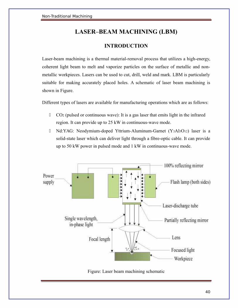
Laser-beam machining is a thermal material-removal process that utilizes a high-energy,
coherent light beam to melt and vaporize particles on the surface of metallic and non-
metallic workpieces. Lasers can be used to cut, drill, weld and mark. LBM is particularly
suitable for making accurately placed holes. A schematic of laser beam machining is
shown in Figure.
Different types of lasers are available for manufacturing operations which are as follows:
CO2 (pulsed or continuous wave): It is a gas laser that emits light in the infrared
region. It can provide up to 25 kW in continuous-wave mode.
Nd:YAG: Neodymium-doped Yttrium-Aluminum-Garnet (Y3Al5O12) laser is a
solid-state laser which can deliver light through a fibre-optic cable. It can provide
up to 50 kW power in pulsed mode and 1 kW in continuous-wave mode.
Figure: Laser beam machining schematic
40
Non-Traditional Machining
Laser beam cutting (drilling)
In drilling, energy transferred (e.g., via a Nd:YAG laser) into the workpiece melts
the material at the point of contact, which subsequently changes into a plasma and
leaves the region.
A gas jet (typically, oxygen) can further facilitate this phase transformation and
departure of material removed.
Laser drilling should be targeted for hard materials and hole geometries that are
difficult to achieve with other methods.
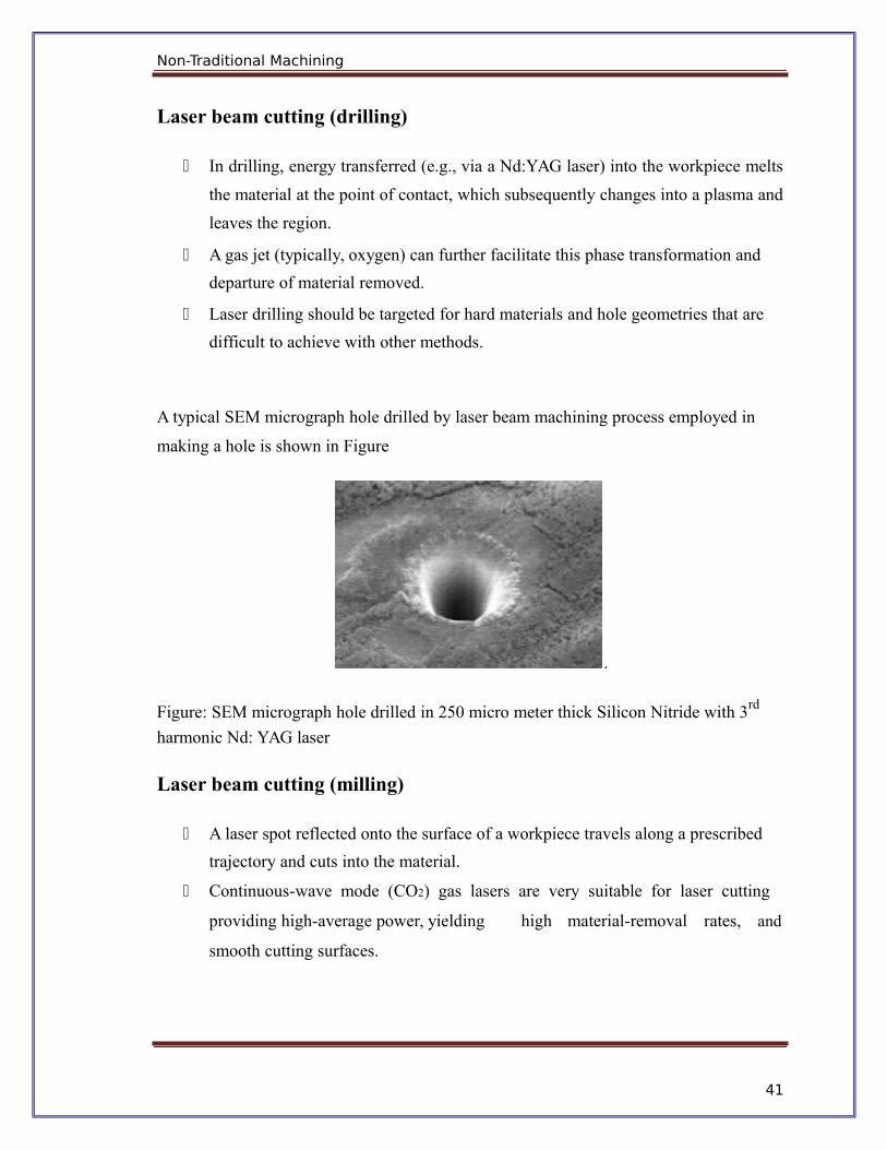
A typical SEM micrograph hole drilled by laser beam machining process employed in
making a hole is shown in Figure
.
Figure: SEM micrograph hole drilled in 250 micro meter thick Silicon Nitride with 3rd
harmonic Nd: YAG laser
Laser beam cutting (milling)
A laser spot reflected onto the surface of a workpiece travels along a prescribed
trajectory and cuts into the material.
Continuous-wave mode (CO2) gas lasers are very suitable for laser cutting
providing high-average power, yielding high material-removal rates, and
smooth cutting surfaces.
41
Non-Traditional Machining
Advantage of laser cutting
No limit to cutting path as the laser point can move any path.
The process is stress less allowing very fragile materials to be laser cut without
any support.
Very hard and abrasive material can be cut.
Sticky materials are also can be cut by this process.
It is a cost effective and flexible process.
High accuracy parts can be machined.
No cutting lubricants required
No tool wear
Narrow heat effected zone
Limitations of laser cutting
Uneconomic on high volumes compared to stamping
Limitations on thickness due to taper
High capital cost
High maintenance cost
Assist or cover gas required
42

ADVANCED WELDING PROCESSES
Friction Welding Process
Principles:
Friction Welding (FRW) is a solid state welding process which produces welds due to the
compressive force contact of workpieces which are either rotating or moving relative to one
another. Heat is produced due to the friction which displaces material plastically from the faying
surfaces. The basic steps explaining the friction welding process are shown in Fig.4.4.1.
In friction welding the heat required to produce the joint is generated by friction heating at the
interface. The components to be joined are first prepared to have smooth, square cut surfaces.
One piece is held stationary while the other is mounted in a motor driven chuck or collet and
rotated against it at high speed. A low contact pressure may be applied initially to permit
cleaning of the surfaces by a burnishing action. This pressure is then increased and contacting
friction quickly generates enough heat to raise the abutting surfaces to the welding temperature.
As soon as this temperature is reached, rotation is stopped and the pressure is maintained or
increased to complete the weld. The softened material is squeezed out to form a flash. A forged
structure is formed in the joint. If desired, the flash can be removed by subsequent machining
action. Friction welding has been used to join steel bars upto 100 mms in diameter and tubes
with outer diameter upto 100 mm.
Inertia welding is a modified form of friction welding, where the moving piece is attached to a
rotating flywheel. The flywheel is brought to a specified rotational speed and is then separated
43

from the driving mo or. The rotating assembly is then pr essed against the statio nary member and
the kinetic energy of the flywhe el is converted into frictional heat. The weld is formed whe n the
flywheel stops its m otion and the pieces r main press ed together. Since the conditions o f the
inertia welding are easily duplic ted, welds f consistent quality can be produced and the process
can be easily automated. The heat affected zones are usually narrow, since t he time peri od is
very short for heating and cooli ng. The radi al and orbital FRW are as shown in Figs. 4.4. 2 and
4.4.3 respectively.
Fi g.4.4.1 Basi c Steps in Friction wel ding
44

Fig .4.4.2 Radial Friction Welding Fig. 4.4.3 O rbital Fricti on Weldin
Advanta ges of Frict ion Welding:
No filler materia , flux or shielding gases are needed.
It is n environment-friendly process without genera tion of smok e, fumes or gases.
No m aterial is melted so the process is in solid state with narrow heat affecte d zone (HAZ).
Oxides can be re moved after the welding process.
In m ost cases, th e weld strength is stronger than the weaker of the two materials being jo ined.
The rocess can be easily aut omated for mass produ ction.
The rocess is ve ry efficient and comparatively very rapid welds are made.
Plant requirements are minim al and wide variety of metals and combination can be welded.
Limitations of Friction Welding:
The process is restricted to j ining round bars or tubes of same diameter (or bars tubes to flat
surfaces), i.e. cap able of bein g rotated about the axis.
Dry bearing and non-forgea ble material s cannot be welded, i.e. one of the component must
be du ctile when ot, to perm t deformati ons.
45

Prep aration and alignment o the workpieces may b e critical for developing uniform ru bbing
and h eating, particularly for pieces having diameters larger than 50 mm.
Capi al equipme t and tooling costs are igh and fre e-machining alloys are d ifficult to w eld.
Applicat ions of Fri tion Welding:
Frict on welded parts in production applications span over w ide products for aerospace,
agricultural, automotive, def ense, marine and oil ind ustries.
Right from tong holds to critical ai rcraft engin e compone nts are friction weld d in producti
on.
Automotive part s that are fri ction welded include g ears, engine valves, axle tubes, driv
eline comp onents, strut rods and s hock absorbers.
Hydraulic piston rods, track rollers, gears, bushing s, axles and similar parts are com only
friction welded by the manufacturers of gricultural equipment.
Frict on welded luminum/c pper joints are in wide usage in the electrical in dustry.
Stainless steels are friction w elded to car bon steels i n various si zes for use in marine sy stems
and ater pumps for home a nd industrial use.
Frict on welded ssemblies are often used to replace expensive casting and forgings.
FRICTION STIR ELDING (FSW) :
Friction Stir Weldin (FSW) is another variant process o f friction w elding. A schematic of the
FSW is shown in Fig . 4.4.4.
46
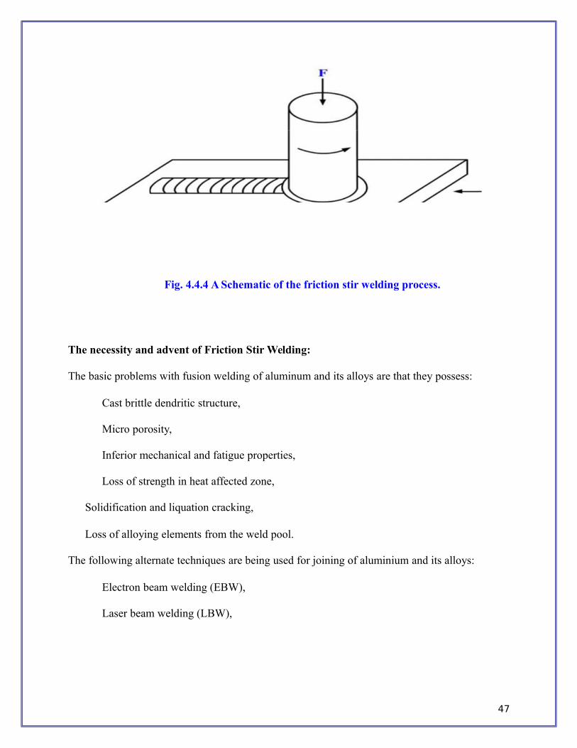
Fig. 4.4.4 A Schematic of the friction stir welding process.
The necessity and advent of Friction Stir Welding:
The basic problems with fusion welding of aluminum and its alloys are that they possess:
Cast brittle dendritic structure,
Micro porosity,
Inferior mechanical and fatigue properties,
Loss of strength in heat affected zone,
Solidification and liquation cracking,
Loss of alloying elements from the weld pool.
The following alternate techniques are being used for joining of aluminium and its alloys:
Electron beam welding (EBW),
Laser beam welding (LBW),
47
Variable polarity plasma arc welding (VPPAW),
Friction stir welding (FSW).
Unique advantages of FSW:
Solid state proce ss.
Routinely used t join difficu lt to fusion weld alloys (e.g., 2xxx & 7xxx alu inum alloys).
Fine grained, re- crystallized microstructu re can be o
btained. No si gnificant al eration of chemical com position.
Eliminates fusio welding problems.
Low r power co sumption, u ser friendly and enviro nment friend ly process.
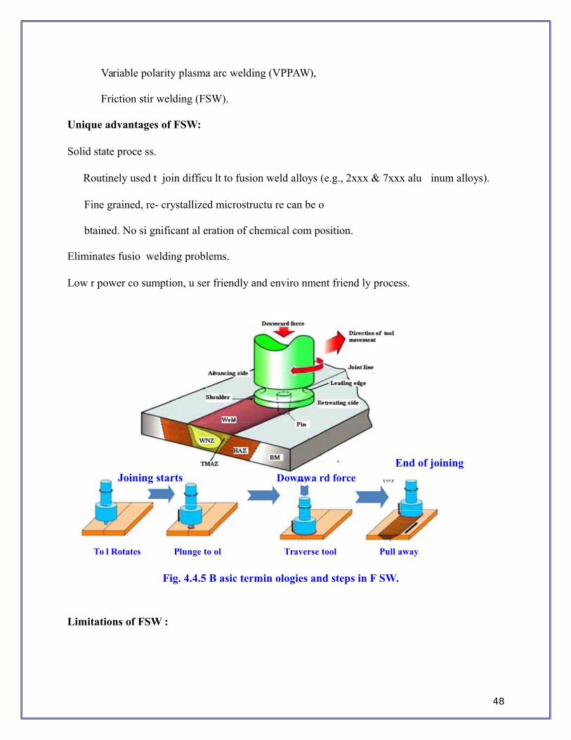
End of joiningJoining starts Downwa rd force
To l Rotates Plunge to ol Traverse tool Pull away
Fig. 4.4.5 B asic termin ologies and steps in F SW.
Limitations of FSW :
48

Rigid and robust fixtures are
required. Visi ble end hole is created.
Inability to mak e filler welds.
49

FSW Typical Applications :
The industrial application of friction stir welding includes following :
Aerospace: Wings, fuselage, cryogenic fuel tanks, aviation fuel tanks, aircraft structure, and
external aircraft throw away tanks.
Marine: Deck panes, bulkheads, floors, hull and superstructures, refrigeration plants,
internal frameworks, marine and transport structures.
Railway: High speed trains, container bodies, railway tankers, good wagon and underground
rolling stocks.
Automotive: Engine and chassis cradles, wheel rims, tailored blanks, armour plate vehicles,
motorcycle and bicycle frames, buses and airfield vehicles, fuel tankers, suspension parts,
crash boxes.
Construction: Bridges, reactors for power and chemical industries, pipelines,
heat exchangers, air conditioners, offshore drilling rigs etc.
Other applications include: Electric motor housing, connectors, busbars, encapsulation of
electronics and joining of aluminum to copper, food tins etc.
50

Metal Casting Process
Manufacturing• Manufacturing in its broadest sense is the process of converting raw materials into useful
products. • It includes
i) Design of the product ii) Selection of raw materials and iii) The sequence of processes through which the product will be manufactured. Casting
Casting is the process of producing metal parts by pouring molten metal into the mouldcavity of the required shape and allowing the metal to solidify. The solidified metal piece iscalled as “casting”.Types of casting
Casting
Conventional MethodsUnconventional Methods
Green sand mouldCO2 Moulding (Strong mould)
Dry sand mould Permanent (Metal mould)Shell Moulding (Thinn mould)Investment casting (Precision)Centrifugal (without core)Continuous Casting (Open)
Advantages• Design flexibility • Reduced costs • Dimensional accuracy • Versatility in production
Disadvantages• Lot of molten metal is wasted in riser & gating • Casting may require machining to remove rough surfaces
51

Sand Casting
52

Sand Casting is simply melting the metal and pouring it into a preformed cavity, called mold,allowing (the metal to solidify and then breaking up the mold to remove casting. In sand castingexpandable molds are used. So for each casting operation you have to form a new mold.• Most widely used casting process. • Parts ranging in size from small to very large • Production quantities from one to millions • Sand mold is used. • Patterns and Cores
– Solid, Split, Match-plate and Cope-and-drag Patterns – Cores – achieve the internal surface of the part
Molds– Sand with a mixture of water and bonding clay – Typical mix: 90% sand, 3% water, and 7% clay – to enhance strength and/or permeability
Sand – Refractory for high temperature
Size and shape of sandSmall grain size -> better surface finishLarge grain size -> to allow escape of gases during pouringIrregular grain shapes -> strengthen molds due to interlocking but to reduce permeability
Types of sanda) Green-sand molds - mixture of sand, clay, and water; “Green" means mold contains moistureat time of pouring. b) Dry-sand mold - organic binders rather than clay and mold is baked to improve strength c) Skin-dried mold - drying mold cavity surface of a green-sand
– mold to a depth of 10 to 25 mm, using torches or heating
Steps in Sand CastingThe cavity in the sand mold is formed by packing sand around a pattern, separating the
mold into two halvesThe mold must also contain gating and riser systemFor internal cavity, a core must be included in moldA new sand mold must be made for each part
1. Pour molten metal into sand mold 2. Allow metal to solidify 3. Break up the mold to remove casting 4. Clean and inspect casting 5. Heat treatment of casting is sometimes required to improve metallurgical properties
53

Types of patterns used in sand casting(a) solid pattern (b) split pattern (c) match-plate pattern (d) cope and drag pattern
Pattern AllowancesFive types of allowances were taken into consideration for various reasons. They are
described as follows:1. Shrinkage allowance2. Draft allowance3. Finish allowance4. Shake allowance5. Distortion allowanceDesirable Mold Properties and Characteristics• Strength - to maintain shape and resist erosion • Permeability - to allow hot air and gases to pass through voids in sand • Thermal stability - to resist cracking on contact with molten metal • Collapsibility - ability to give way and allow casting to shrink without cracking the casting • Reusability - can sand from broken mold be reused to make other molds.
54
Testing of Mould & Core sand1) Preparation of standard test specimen 2) Mould hardness test 3) Core hardness test 4) Moisture content test on foundry sand 5) Sieve analysis 6) Clay content test 7) Permeability test 8) Compression, shear test
Other Expendable Mold Casting• Shell Molding • Vacuum Molding • Expanded Polystyrene Process • Investment casting • Plaster and Ceramic Mold casting
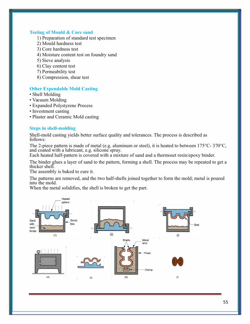
Steps in shell-moldingShell-mold casting yields better surface quality and tolerances. The process is described asfollows:The 2-piece pattern is made of metal (e.g. aluminum or steel), it is heated to between 175°C- 370°C,and coated with a lubricant, e.g. silicone spray.Each heated half-pattern is covered with a mixture of sand and a thermoset resin/epoxy binder.
The binder glues a layer of sand to the pattern, forming a shell. The process may be repeated to get a thicker shell.The assembly is baked to cure it.
The patterns are removed, and the two half-shells joined together to form the mold; metal is pouredinto the mold.When the metal solidifies, the shell is broken to get the part.
55
Advantages
Smoother cavity surface permits easier flow of molten metal and better surface finish on castingGood dimensional accuracy Machining often not requiredMold collapsibility usually avoids cracks in casting Can be mechanized for mass production
DisadvantagesMore expensive metal patternDifficult to justify for small quantities
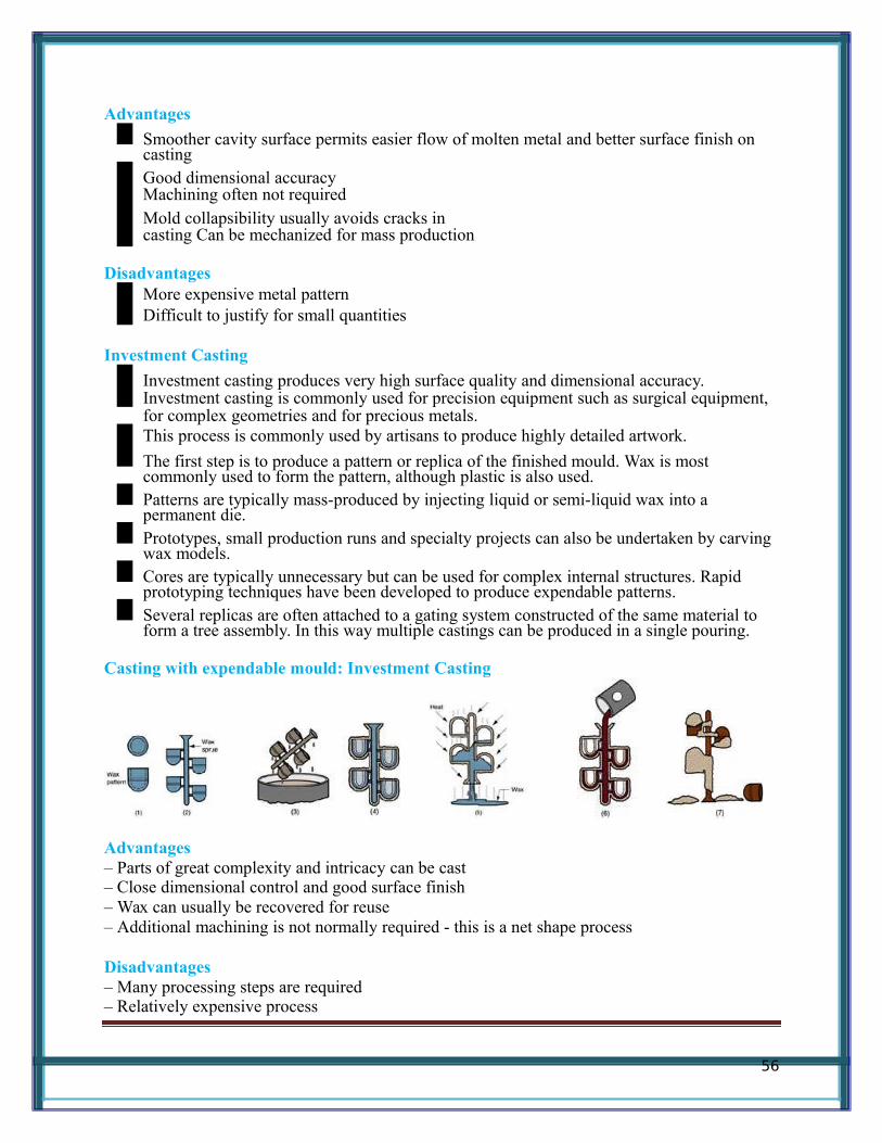
Investment Casting
Investment casting produces very high surface quality and dimensional accuracy. Investment casting is commonly used for precision equipment such as surgical equipment, for complex geometries and for precious metals.This process is commonly used by artisans to produce highly detailed artwork.
The first step is to produce a pattern or replica of the finished mould. Wax is most commonly used to form the pattern, although plastic is also used.Patterns are typically mass-produced by injecting liquid or semi-liquid wax into a permanent die.Prototypes, small production runs and specialty projects can also be undertaken by carving wax models.Cores are typically unnecessary but can be used for complex internal structures. Rapid prototyping techniques have been developed to produce expendable patterns.Several replicas are often attached to a gating system constructed of the same material to form a tree assembly. In this way multiple castings can be produced in a single pouring.
Casting with expendable mould: Investment Casting
Advantages– Parts of great complexity and intricacy can be cast – Close dimensional control and good surface finish – Wax can usually be recovered for reuse – Additional machining is not normally required - this is a net shape process
Disadvantages– Many processing steps are required – Relatively expensive process
56
Plaster Molding• Similar to sand casting except mold is made of plaster of Paris (gypsum - CaSO4-2H2O) • Plaster and water mixture is poured over plastic or metal pattern to make a mold
Advantages– Good dimensional accuracy and surface finish – Capability to make thin cross-sections in casting
Disadvantages
Moisture in plaster mold causes problems: Mold must be baked to remove moisture
Mold strength is lost when is over-baked, yet moisture content can cause defects in productPlaster molds cannot stand high temperatures
Permanent Mold CastingBasic Permanent Mold Process– Uses a metal mold constructed of two sections designed for easy, precise opening and closing
– Molds for lower melting point alloys: steel or cast iron and Molds for steel: refractory material,due to the very high pouring temperatures
Permanent Mold Casting Process
The two halves of the mold are made of metal, usually cast iron, steel, or refractoryalloys. The cavity, including the runners and gating system are machined into the moldhalves.For hollow parts, either permanent cores (made of metal) or sand-bonded ones may beused, depending on whether the core can be extracted from the part without damage aftercasting.The surface of the mold is coated with clay or other hard refractory material – thisimproves the life of the mold. Before molding, the surface is covered with a spray ofgraphite or silica, which acts as a lubricant. This has two purposes – it improves the flowof the liquid metal, and it allows the cast part to be withdrawn from the mold more easily.The process can be automated, and therefore yields high throughput rates.It produces very good tolerance and surface finish.
It is commonly used for producing pistons used in car engines; gear blanks, cylinderheads, and other parts made of low melting point metals, e.g. copper, bronze, aluminum,magnesium, etc.
Advantage- Good surface finish and dimensional control and Fine grain due to rapid solidification.
Disadvantage- Simple geometric part, expensive mold.Example
It is commonly used for producing pistons used in car engines; gear blanks, cylinderheads, and other parts made of low melting point metals, e.g. copper, bronze, aluminum,magnesium, etc.
57

Basic Permanent Mold Process
Advantages– Good dimensional control and surface finish – More rapid solidification caused by the cold metal mold results in a finer grain structure, sostronger castings are produced
Limitations• Generally limited to metals of lower melting point • Simple part geometries compared to sand casting because of the need to open the mold • High cost of mold • Due to high mold cost, process is best suited to automated high volume production
Testing of Mould & Core sand1) Preparation of standard test specimen 2) Mould hardness test 3) Core hardness test 4) Moisture content test on foundry sand 5) Sieve analysis 6) Clay content test 7) Permeability test 8) Compression, shear test
Die Casting• Die casting is a very commonly used type of permanent mold casting process. • It is used for producing many components of home appliances (e.g rice cookers, stoves, fans,washing and drying machines, fridges), motors, toys and hand-tools • The molten metal is injected into mold cavity (die) under high pressure (7-350MPa). Pressure maintained during solidification.• Hot Chamber (Pressure of 7 to 35MPa)
• The injection system is submerged under the molten metals (low melting point metals such aslead, zinc, tin and magnesium)
• Cold Chamber (Pressure of 14 to 140MPa) • External melting container (in addition aluminum, brass and magnesium) Molds are made of tool steel, mold steel, maraging steel, tungsten and molybdenum.• Single or multiple cavity • Lubricants and Ejector pins to free the parts
58

• Venting holes and passageways in die • Formation of flash that needs to be trimmed
Properties of die-casting1) Huge numbers of small, light castings can be produced with great accuracy. 2) Little surface finishing is required. 3) Permanent mold (dies can be used over and over)
Advantages– High production, Economical, close tolerance, good surface finish, thin sections, rapid cooling
Hot-Chamber Die CastingIn a hot chamber process (used for Zinc alloys, magnesium) the pressure chamber
connected to the die cavity is filled permanently in the molten metal.The basic cycle of operation is as follows:
(i) die is closed and gooseneck cylinder is filled with molten metal;
(ii) plunger pushes molten metal through gooseneck passage and nozzle and into the diecavity; metal is held under pressure until it solidifies;
(iii) die opens and cores, if any, are retracted; casting stays in ejector die; plunger returns,pulling molten metal back through nozzle and gooseneck;
(iv)ejector pins push casting out of ejector die. As plunger uncovers inlet hole, molten metalrefills gooseneck cylinder.
The hot chamber process is used for metals that (a) have low melting points and (b) do not alloy with the die material, steel; common examples are tin, zinc, and lead.
Cold Chamber Die Casting
In a cold chamber process, the molten metal is poured into the cold chamber in each cycle. The operating cycle is
(i) Die is closed and molten metal is ladled into the cold chamber cylinder;
(ii) plunger pushes molten metal into die cavity; the metal is held under high pressureuntil it solidifies;
(iii) die opens and plunger follows to push the solidified slug from the cylinder, ifthere are cores, they are retracted away;
(iv) ejector pins push casting off ejector die and plunger returns to original position
59
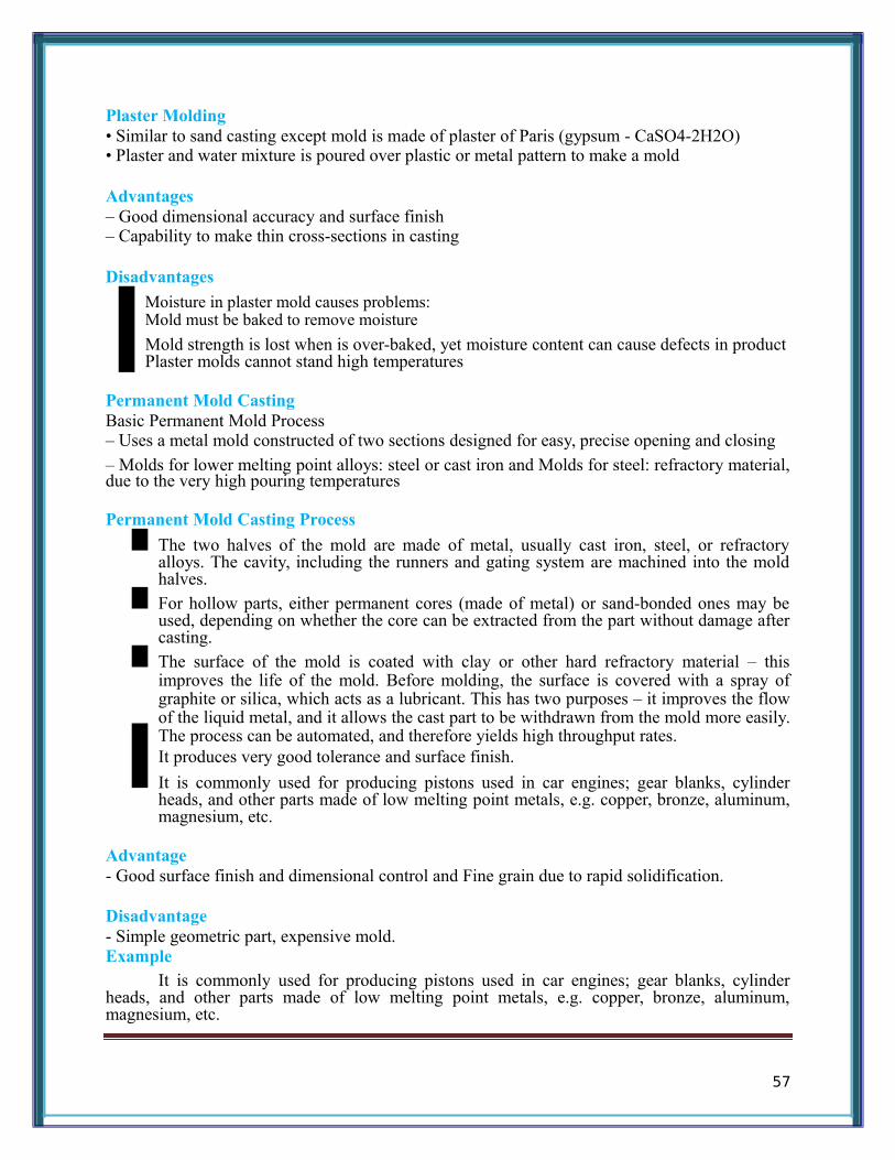
This process is particularly useful for high melting point metals such as Aluminum, and Copper (and its alloys).
Advantages– Economical for large production quantities – Good dimensional accuracy and surface finish – Thin sections are possible – Rapid cooling provides small grain size and good strength to casting
Disadvantages– Generally limited to metals with low metal points – Part geometry must allow removal from die cavity
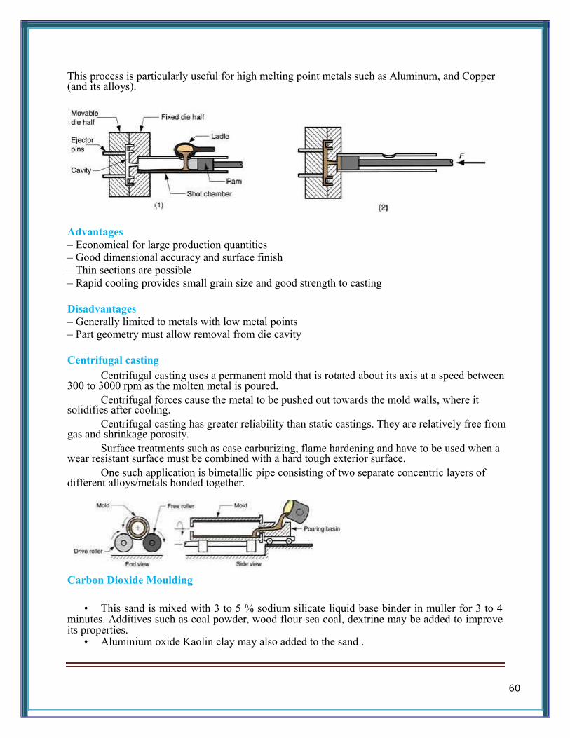
Centrifugal castingCentrifugal casting uses a permanent mold that is rotated about its axis at a speed between
300 to 3000 rpm as the molten metal is poured.Centrifugal forces cause the metal to be pushed out towards the mold walls, where it
solidifies after cooling.Centrifugal casting has greater reliability than static castings. They are relatively free from
gas and shrinkage porosity.Surface treatments such as case carburizing, flame hardening and have to be used when a
wear resistant surface must be combined with a hard tough exterior surface.One such application is bimetallic pipe consisting of two separate concentric layers of
different alloys/metals bonded together.
Carbon Dioxide Moulding
• This sand is mixed with 3 to 5 % sodium silicate liquid base binder in muller for 3 to 4minutes. Additives such as coal powder, wood flour sea coal, dextrine may be added to improveits properties.
• Aluminium oxide Kaolin clay may also added to the sand .
60

• Patterns used in this method may be coated with Zinc of 0.05 mm to 0.13 mm and thenspraying a layer of aluminium or brass of about 0.25 mm thickness for good surface finish andgood results.
Advantages• Operation is speedy since we can use the mould and cores immediately after processing. • Heavy and rush orders • Floor space requirement is less • Semi skilled labour may be used.
DisadvantagesDifficult in reusing the moulding sand.
Process Advantages Disadvantages ExamplesSand Wide range of poor finish, wide engine blocks,
metals, sizes, tolerance cylinder headsshapes, low cost
Shell mold better accuracy, limited part size connecting rods,finish, higher gear housingsproduction rate
Expendable Wide range of patterns have low cylinder heads,pattern metals, sizes, strength brake components
shapesPlaster mold complex shapes, non-ferrous metals, prototypes of
good surface finish low production rate mechanical partsCeramic mold complex shapes, small sizes impellers, injection
high accuracy, mold toolinggood finish
Investment complex shapes, small parts, jewelleryexcellent finish expensive
Permanent mold good finish, low Costly mold, gears, gearporosity, high simpler shapes only housingsproduction rate
Die Excellent costly dies, small precision gears,dimensional parts, camera bodies, caraccuracy, high non-ferrous metals wheelsproduction rate
Centrifugal Large cylindrical Expensive, limited pipes, boilers,parts, good quality shapes flywheels
FurnacesCupola Furnace
• A continuous flow of iron emerges from the bottom of the furnace. • Depending on the size of the furnace, the flow rate can be as high as 100 tonnes per hour.
At the metal melts it is refined to some extent, which removes contaminants. This makes thisprocess more suitable than electric furnaces for dirty charges.
61
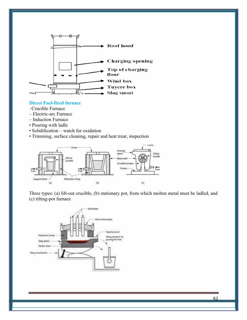
Direct Fuel-fired furnace–Crucible Furnace– Electric-arc Furnace – Induction Furnace • Pouring with ladle • Solidification – watch for oxidation • Trimming, surface cleaning, repair and heat treat, inspection
Three types: (a) lift-out crucible, (b) stationary pot, from which molten metal must be ladled, and(c) tilting-pot furnace
62
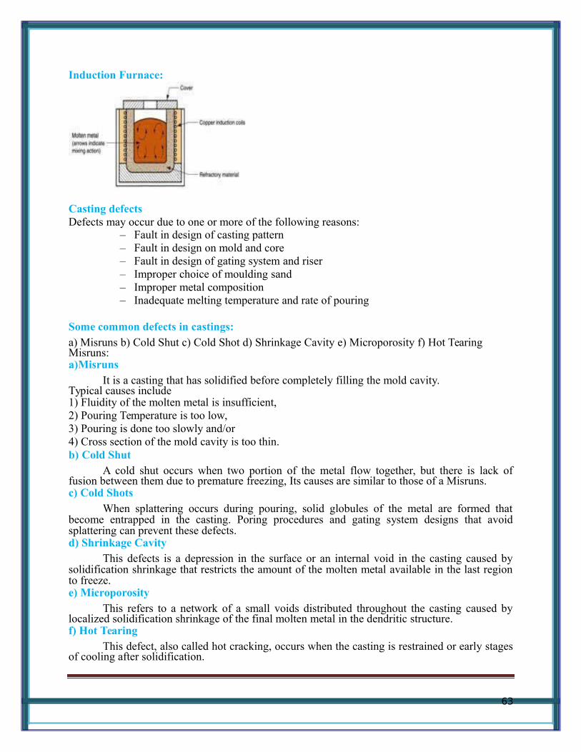
Induction Furnace:
Casting defectsDefects may occur due to one or more of the following reasons:
– Fault in design of casting pattern – Fault in design on mold and core – Fault in design of gating system and riser – Improper choice of moulding sand – Improper metal composition – Inadequate melting temperature and rate of pouring
Some common defects in castings:a) Misruns b) Cold Shut c) Cold Shot d) Shrinkage Cavity e) Microporosity f) Hot TearingMisruns: a)Misruns
It is a casting that has solidified before completely filling the mold cavity.Typical causes include 1) Fluidity of the molten metal is insufficient, 2) Pouring Temperature is too low, 3) Pouring is done too slowly and/or 4) Cross section of the mold cavity is too thin. b) Cold Shut
A cold shut occurs when two portion of the metal flow together, but there is lack offusion between them due to premature freezing, Its causes are similar to those of a Misruns.c) Cold Shots
When splattering occurs during pouring, solid globules of the metal are formed thatbecome entrapped in the casting. Poring procedures and gating system designs that avoidsplattering can prevent these defects.d) Shrinkage Cavity
This defects is a depression in the surface or an internal void in the casting caused bysolidification shrinkage that restricts the amount of the molten metal available in the last regionto freeze.e) Microporosity
This refers to a network of a small voids distributed throughout the casting caused bylocalized solidification shrinkage of the final molten metal in the dendritic structure.f) Hot Tearing
This defect, also called hot cracking, occurs when the casting is restrained or early stagesof cooling after solidification.
63
JOINING PROCESSES
WeldingWelding is a materials joining process which produces coalescence of materials by
heating them to suitable temperatures with or without the application of pressure or by theapplication of pressure alone, and with or without the use of filler material.
Welding is used for making permanent joints.
It is used in the manufacture of automobile bodies, aircraft frames, railway wagons,machine frames, structural works, tanks, furniture, boilers, general repair work and ship building.
Classification of welding processes
(i) Arc welding
•••••••
C
a
r
b
o
n
a
r
c
M
e
t
a
l
a
r
c
64

M
T
n
gs
te
n
in
er
t
g
as
Pl
as
m
a
ar
c
S
u
b
m
er
g
e
d
ar
c
El
ec
tr
o-
sl
a
g
65

(
•••
O
A
O
66

iii) Resistance Welding
ButtSpotSeamProjectionPercussion
(iv)Thermit Welding
67

(v)Solid State WeldingFrictionUltrasonicDiffusionExplosive
(vi) Newer WeldingElectron-beamLaser
(vii)Related ProcessOxy-acetylene cuttingArc cuttingHard facingBrazingSoldering
Welding practice & equipmentSTEPS :• Prepare the edges to be joined and maintain the proper position
• Open the acetylene valve and ignite the gas at tip of the torch
• Hold the torch at about 45deg to the work piece plane
• Inner flame near the work piece and filler rod at about 30 – 40 deg
• Touch filler rod at the joint and control the movement according to the flow of thematerial
Two Basic Types of AW Electrodes Consumable – consumed during welding process
Source of filler metal in arc welding Nonconsumable – not consumed during welding process
Filler metal must be added separately
Consumable ElectrodesForms of consumable electrodes
• Welding rods (a.k.a. sticks) are 9 to 18 inches and 3/8 inch or less in diameter andmust be changed frequently
• Weld wire can be continuously fed from spools with long lengths of wire,avoiding frequent interruptions
In both rod and wire forms, electrode is consumed by arc and added to weld joint as filler metal.
Nonconsumable Electrodes Made of tungsten which resists melting Gradually depleted during welding (vaporization is principal mechanism) Any filler metal must be supplied by a separate wire fed into weld pool
FluxA substance that prevents formation of oxides and other contaminants in welding, or
dissolves them and facilitates removal Provides protective atmosphere for welding Stabilizes arc Reduces spattering
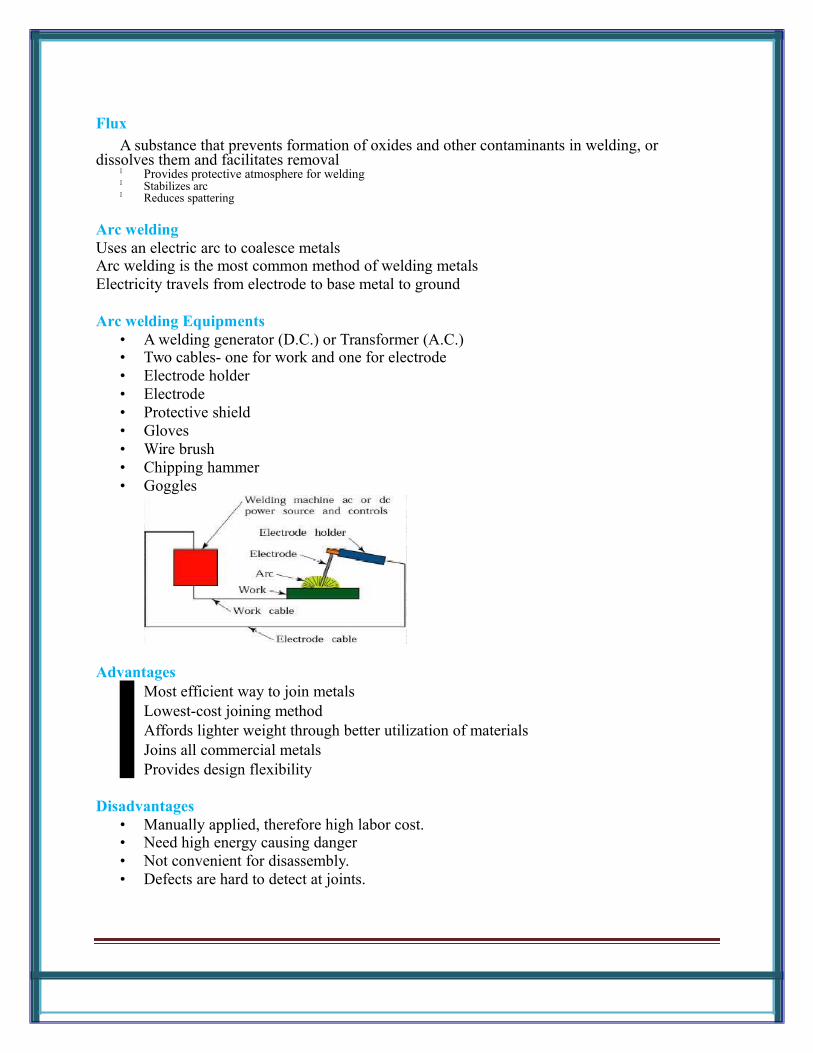
Arc weldingUses an electric arc to coalesce metalsArc welding is the most common method of welding metalsElectricity travels from electrode to base metal to ground
Arc welding Equipments• A welding generator (D.C.) or Transformer (A.C.) • Two cables- one for work and one for electrode • Electrode holder • Electrode • Protective shield • Gloves • Wire brush • Chipping hammer • Goggles
AdvantagesMost efficient way to join metalsLowest-cost joining methodAffords lighter weight through better utilization of materialsJoins all commercial metalsProvides design flexibility
Disadvantages• Manually applied, therefore high labor cost. • Need high energy causing danger • Not convenient for disassembly. • Defects are hard to detect at joints.
GAS WELDING
Sound weld is obtained by selecting proper size of flame, filler material and method of moving torch
The temperature generated during the process is 33000c.
When the metal is fused, oxygen from the atmosphere and the torch combines with molten metal and formsoxides, results defective weld
Fluxes are added to the welded metal to remove oxides
Common fluxes used are made of sodium, potassium. Lithium and borax.
Flux can be applied as paste, powder, liquid. solid coating or gas.
GAS WELDING EQUIPMENT
1.Gas Cylinders PressureOxygen – 125 kg/cm2Acetylene – 16 kg/cm22. RegulatorsWorking pressure of oxygen 1 kg/cm2 Working pressure of acetylene 0.15 kg/cm2Working pressure varies depends upon the thickness of the work pieces welded.3. Pressure Gauges 4. Hoses 5. Welding torch 6. Check valve 7. Non return valve
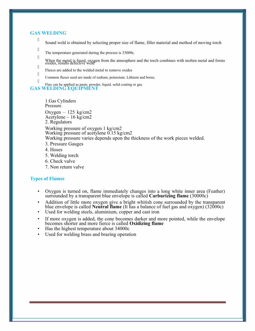
Types of Flames
• Oxygen is turned on, flame immediately changes into a long white inner area (Feather)surrounded by a transparent blue envelope is called Carburizing flame (30000c)
• Addition of little more oxygen give a bright whitish cone surrounded by the transparentblue envelope is called Neutral flame (It has a balance of fuel gas and oxygen) (32000c)
• Used for welding steels, aluminium, copper and cast iron
• If more oxygen is added, the cone becomes darker and more pointed, while the envelopebecomes shorter and more fierce is called Oxidizing flame
• Has the highest temperature about 34000c • Used for welding brass and brazing operation
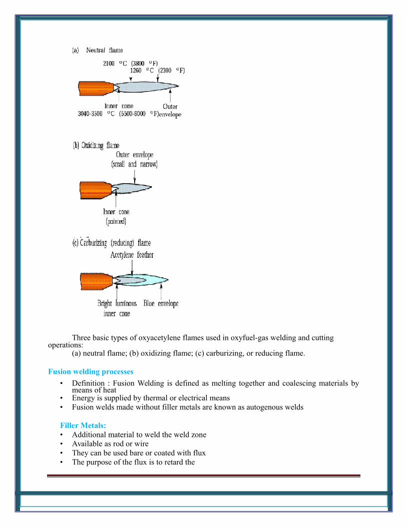
Three basic types of oxyacetylene flames used in oxyfuel-gas welding and cutting operations:
(a) neutral flame; (b) oxidizing flame; (c) carburizing, or reducing flame.
Fusion welding processes
• Definition : Fusion Welding is defined as melting together and coalescing materials bymeans of heat
• Energy is supplied by thermal or electrical means • Fusion welds made without filler metals are known as autogenous welds
Filler Metals:• Additional material to weld the weld zone • Available as rod or wire • They can be used bare or coated with flux • The purpose of the flux is to retard the
Shielded metal arc welding process
• An electric arc is generated between a coated electrode and the parent metal
• The coated electrode carries the electric current to form the arc, produces a gas to controlthe atmosphere and provides filler metal for the weld bead
• Electric current may be AC or DC. If the current is DC, the polarity will affect the weldsize and application
Process• Intense heat at the arc melts the tip of the electrode • Tiny drops of metal enter the arc stream and are deposited on the parent metal
• As molten metal is deposited, a slag forms over the bead which serves as aninsulation against air contaminants during cooling
• After a weld „pass is allowed the cool, the oxide layer is removed by a chipping‟hammer and then cleaned with a wirebrush before the next pass.
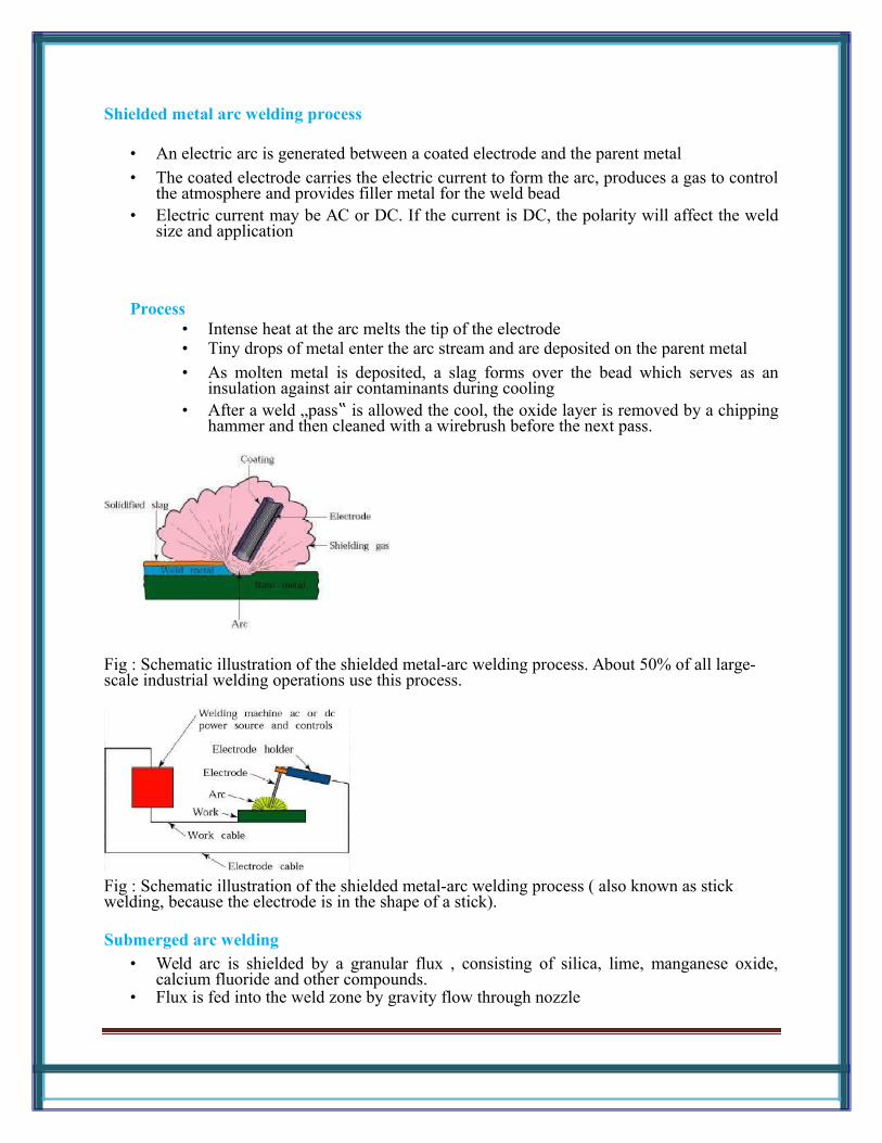
Fig : Schematic illustration of the shielded metal-arc welding process. About 50% of all large-scale industrial welding operations use this process.
Fig : Schematic illustration of the shielded metal-arc welding process ( also known as stick welding, because the electrode is in the shape of a stick).
Submerged arc welding• Weld arc is shielded by a granular flux , consisting of silica, lime, manganese oxide,
calcium fluoride and other compounds. • Flux is fed into the weld zone by gravity flow through nozzle
• Thick layer of flux covers molten metal
• Flux acts as a thermal insulator ,promoting deep penetration of heat into the work piece • Consumable electrode is a coil of bare round wire fed automatically through a tube • Power is supplied by 3-phase or 2-phase power lines
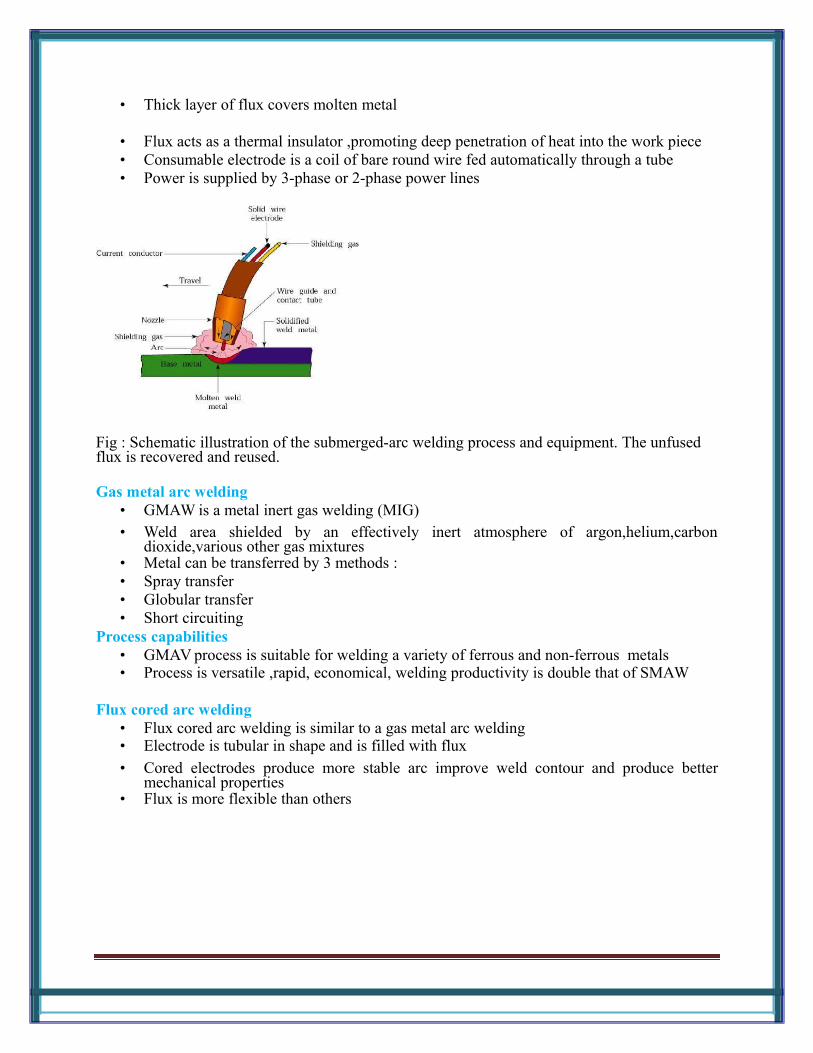
Fig : Schematic illustration of the submerged-arc welding process and equipment. The unfused flux is recovered and reused.
Gas metal arc welding• GMAW is a metal inert gas welding (MIG) • Weld area shielded by an effectively inert atmosphere of argon,helium,carbon
dioxide,various other gas mixtures • Metal can be transferred by 3 methods : • Spray transfer • Globular transfer • Short circuiting
Process capabilities• GMAV process is suitable for welding a variety of ferrous and non-ferrous metals • Process is versatile ,rapid, economical, welding productivity is double that of SMAW
Flux cored arc welding• Flux cored arc welding is similar to a gas metal arc welding • Electrode is tubular in shape and is filled with flux
• Cored electrodes produce more stable arc improve weld contour and produce bettermechanical properties
• Flux is more flexible than others

Fig : Schematic illustration of the flux-cored arc-welding process. This operation is similar to gasmetal-arc welding.
Electro gas Welding• EGW is welding the edges of sections vertically in one pass with the pieces placed edge
to edge • Similar to Electro gas welding • Weld metal is deposited into weld cavity between the two pieces to be joined • Difference is Arc is started between electrode tip and bottom part of the part to be welded• Flux added first and then melted by the heat on the arc • Molten slag reaches the tip of the electrode and the arc is extinguished • Heat is then continuously produced by electrical resistance of the molten slag • Single or multiple solid as well as flux-cored electrodes may be used
Process capabilities• Weld thickness ranges from 12mm to 75mm • Metals welded are steels, titanium, aluminum alloys
• Applications are construction of bridges, pressure vessels, thick walled and largediameter pipes, storage tanks and ships.
Fig : Schematic illustration of the electrogas welding process
Brazing

It is a low temperature joining process. It is performed at temperatures above 840º F and itgenerally affords strengths comparable to those of the metal which it joins. It is low temperaturein that it is done below the melting point of the base metal. It is achieved by diffusion withoutfusion (melting) of the base
Brazing can be classified asTorch brazingDip brazingFurnace brazingInduction brazing
Advantages• Dissimilar metals which canot be welded can be joined by brazing • Very thin metals can be joined • Metals with different thickness can be joined easily
• In brazing thermal stresses are not produced in the work piece. Hence there is nodistortion
• Using this process, carbides tips are brazed on the steel tool holders
Disadvantages• Brazed joints have lesser strength compared to welding • Joint preparation cost is more • Can be used for thin sheet metal sections
Soldering• It is a low temperature joining process. It is performed at temperatures below 840ºF for
joining.• Soldering is used for,
• Sealing, as in automotive radiators or tin cans • Electrical Connections • Joining thermally sensitive components • Joining dissimilar metals
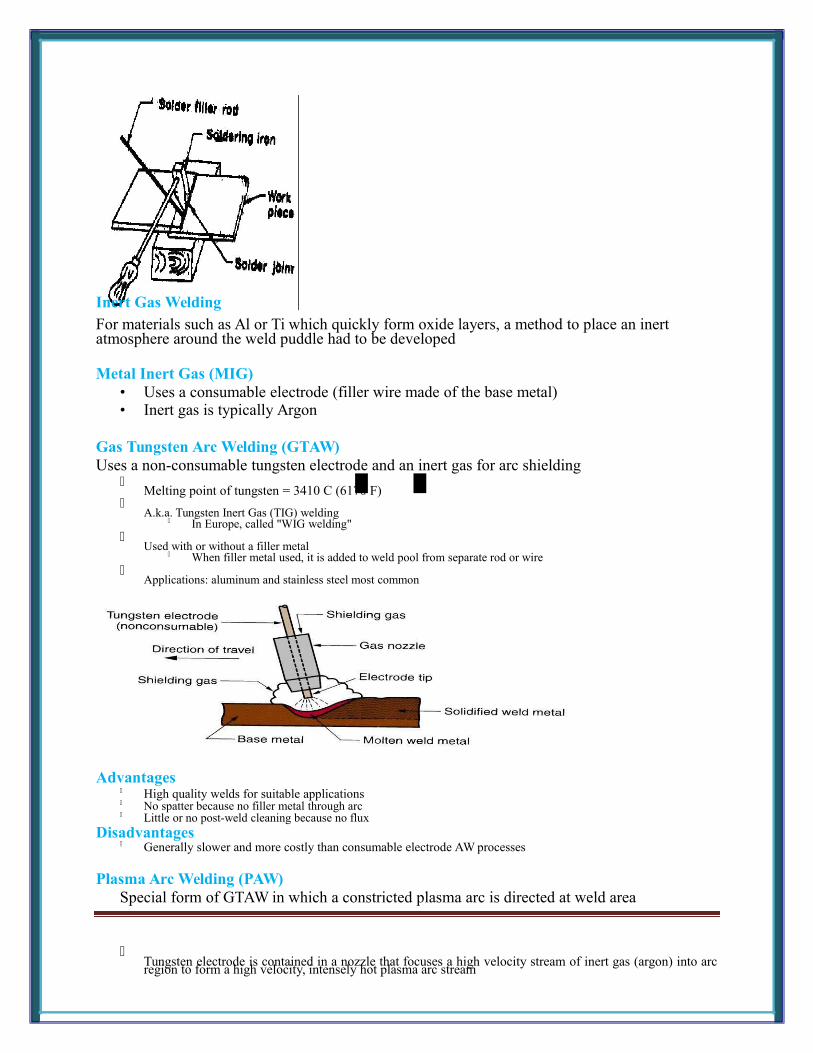
Inert Gas WeldingFor materials such as Al or Ti which quickly form oxide layers, a method to place an inert atmosphere around the weld puddle had to be developed
Metal Inert Gas (MIG)• Uses a consumable electrode (filler wire made of the base metal) • Inert gas is typically Argon
Gas Tungsten Arc Welding (GTAW)Uses a non-consumable tungsten electrode and an inert gas for arc shielding
Melting point of tungsten = 3410 C (6170 F)
A.k.a. Tungsten Inert Gas (TIG) welding
In Europe, called "WIG welding"
Used with or without a filler metal When filler metal used, it is added to weld pool from separate rod or wire
Applications: aluminum and stainless steel most common
Advantages High quality welds for suitable applications No spatter because no filler metal through arc Little or no post-weld cleaning because no flux
Disadvantages Generally slower and more costly than consumable electrode AW processes
Plasma Arc Welding (PAW)Special form of GTAW in which a constricted plasma arc is directed at weld area
Tungsten electrode is contained in a nozzle that focuses a high velocity stream of inert gas (argon) into arcregion to form a high velocity, intensely hot plasma arc stream
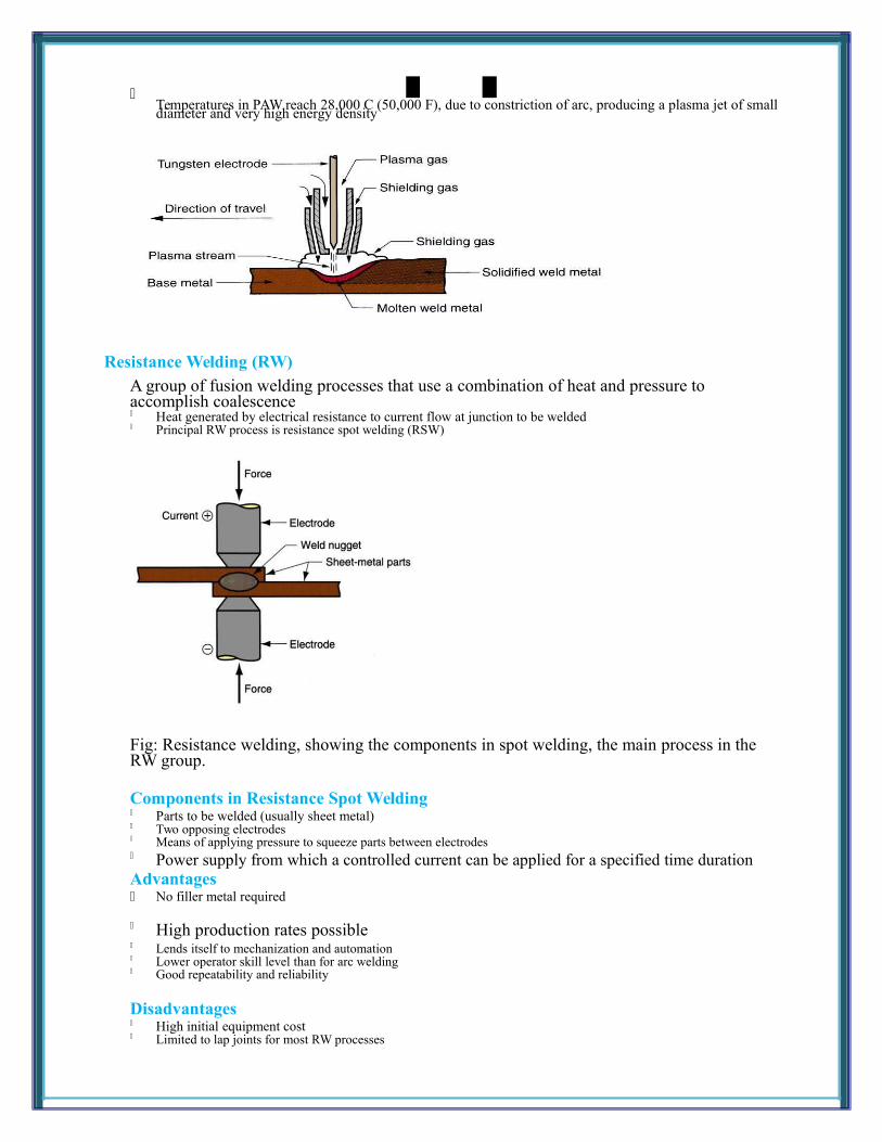
Temperatures in PAW reach 28,000 C (50,000 F), due to constriction of arc, producing a plasma jet of smalldiameter and very high energy density
Resistance Welding (RW)A group of fusion welding processes that use a combination of heat and pressure to accomplish coalescence Heat generated by electrical resistance to current flow at junction to be welded Principal RW process is resistance spot welding (RSW)
Fig: Resistance welding, showing the components in spot welding, the main process in the RW group.
Components in Resistance Spot Welding Parts to be welded (usually sheet metal) Two opposing electrodes Means of applying pressure to squeeze parts between electrodes Power supply from which a controlled current can be applied for a specified time duration Advantages No filler metal required
High production rates possible Lends itself to mechanization and automation Lower operator skill level than for arc welding Good repeatability and reliability
Disadvantages High initial equipment cost Limited to lap joints for most RW processes

Resistance Seam Welding
Electron Beam Welding (EBW)Fusion welding process in which heat for welding is provided by a highly-focused, high-
intensity stream of electrons striking work surface Electron beam gun operates at:
High voltage (e.g., 10 to 150 kV typical) to accelerate electrons Beam currents are low (measured in milliamps)
Power in EBW not exceptional, but power density is
Advantages High-quality welds, deep and narrow profiles Limited heat affected zone, low thermal distortion High welding speeds No flux or shielding gases needed
Disadvantages High equipment cost Precise joint preparation & alignment required Vacuum chamber required Safety concern: EBW generates x-rays
Laser Beam Welding (LBW)
Fusion welding process in which coalescence is achieved by energy of a highly concentrated, coherent light beam focused on joint Laser = "light amplification by stimulated emission of radiation" LBW normally performed with shielding gases to prevent oxidation

Filler metal not usually added High power density in small area, so LBW often used for small parts
Comparison: LBW vs. EBW No vacuum chamber required for LBW No x-rays emitted in LBW Laser beams can be focused and directed by optical lenses and mirrors LBW not capable of the deep welds and high depth-to-width ratios of EBW
Maximum LBW depth = ~ 19 mm (3/4 in), whereas EBW depths = 50 mm (2 in)
Thermit Welding (TW)FW process in which heat for coalescence is produced by superheated molten metal from the chemical reaction of thermite Thermite = mixture of Al and Fe3O4 fine powders that produce an exothermic reaction when ignited Also used for incendiary bombs Filler metal obtained from liquid metal Process used for joining, but has more in common with casting than welding
Fig: Thermit welding: (1) Thermit ignited; (2) crucible tapped, superheated metal flows into mold; (3) metal solidifies to produce weld joint.
Applications Joining of railroad rails Repair of cracks in large steel castings and forgings Weld surface is often smooth enough that no finishing is required
Diffusion Welding (DFW)SSW process uses heat and pressure, usually in a controlled atmosphere, with sufficient time
for diffusion and coalescence to occur Temperatures 0.5 Tm Plastic deformation at surfaces is minimal Primary coalescence mechanism is solid state diffusion Limitation: time required for diffusion can range from seconds to hours

Applications Joining of high-strength and refractory metals in aerospace and nuclear industries Can be used to join either similar and dissimilar metals For joining dissimilar metals, a filler layer of different metal is often sandwiched between base metals to
promote diffusion
Friction Welding (FRW)SSW process in which coalescence is achieved by frictional heat combined with pressure When properly carried out, no melting occurs at faying surfaces No filler metal, flux, or shielding gases normally used Process yields a narrow HAZ Can be used to join dissimilar metals Widely used commercial process, amenable to automation and mass production
Fig: Friction welding (FRW): (1) rotating part, no contact; (2) parts brought into contact to generate friction heat; (3) rotation stopped and axial pressure applied; and (4) weld created.
Applications Shafts and tubular parts Industries: automotive, aircraft, farm equipment, petroleum and natural gas
Limitations At least one of the parts must be rotational Flash must usually be removed Upsetting reduces the part lengths (which must be taken into consideration in product design)