non-welded double wall grease duct ... - kitchen ventilation double wall oim.pdfa0018672 april 2018...
TRANSCRIPT
A0018672 April 2018 Rev. 27
Non-Welded Double Wall Grease Duct/Type HT Chimney Systems
Installation, Operation, and Maintenance Manual
Save these instructions. This document is the property of the owner of this equipment and is required for future maintenance. Leave this document with the owner when installation or service is complete.
FOR YOUR SAFETY
TWO MAJOR CAUSES OF GREASE DUCT RELATED FIRES: (1) FAILURE TO MAINTAIN REQUIRED CLEARANCE (AIR SPACE) TO COMBUSTIBLE MATERIALS AND (2) FAILURE TO CLEAN GREASE LADEN DUCTS. IT IS OF UTMOST IMPORTANCE THAT THIS GREASE DUCT BE INSTALLED ONLY IN ACCORDANCE WITH THESE INSTRUCTIONS. DO NOT INSTALL GREASE DUCT WITHOUT FIRST READING THESE INSTRUCTIONS VERY CAREFULLY.
A MAJOR CAUSE OF CHIMNEY RELATED FIRES IS FAILURE TO MAINTAIN REQUIRED CLEARANCES (AIR SPACE) TO COMBUSTIBLE MATERIALS UNENCLOSED. IT IS OF UTMOST IMPORTANCE THAT THIS CHIMNEY BE INSTALLED ONLY IN ACCORDANCE WITH THESE INSTRUCTIONS.
RECEIVING AND INSPECTION
EXAMINE ALL COMPONENTS FOR POSSIBLE SHIPPING DAMAGE PRIOR TO INSTALLATION. DIFFERENT MANUFACTURERS HAVE DIFFERENT JOINT SYSTEMS AND ADHESIVES. DO NOT MIX PIPE, FITTINGS, OR JOINING METHODS FROM DIFFERENT MANUFACTURERS.

2
3
TABLE OF CONTENTS WARRANTY ....................................................................................................................................................... 4 LISTINGS ........................................................................................................................................................... 4 CLASSIFICATIONS ........................................................................................................................................... 5 APPLICATION .................................................................................................................................................... 5
Grease Ducts ................................................................................................................................................. 5 Chimneys ....................................................................................................................................................... 6 Clearances ..................................................................................................................................................... 7
MECHANICAL .................................................................................................................................................... 8 Joint Sealant .................................................................................................................................................. 8 Grease Duct & Chimney Joint Assembly ....................................................................................................... 9 Adjustable Duct, Chimney & Transition Connection .................................................................................... 10 Adjustable Duct, Chimney Standard Installation.......................................................................................... 12 Offset Distance ............................................................................................................................................ 14 Risers – Factory & Field (Bolted) Risers ...................................................................................................... 15 Duct Drains .................................................................................................................................................. 17 Manifold Tee ................................................................................................................................................ 17 Access Door (Tee Cap) Assembly ............................................................................................................... 18 Transition Plate ............................................................................................................................................ 19 Chimney Adapter Plate ................................................................................................................................ 20 Prevention of Grease Accumulation in Horizontal Grease Duct .................................................................. 21 Alignment & Bracing of Grease Duct ........................................................................................................... 21
Horizontal Support & Support Spacing .................................................................................................... 21 Vertical Support & Vertical Support Spacing ........................................................................................... 23
Through Penetration & Fire Stops ............................................................................................................... 36 Annular Distance – Fire Stop ................................................................................................................... 36 Annular Distance – 2R Type HT Clearance ............................................................................................ 37 Floor & Ceiling Fire Stop Installation ....................................................................................................... 38 Wall Fire Stop Installation ........................................................................................................................ 39
Grease Duct Assembly Examples ............................................................................................................... 40 METHODS USED TO TEST DUCT AFTER ASSEMBLY ................................................................................ 45
Method 1 – Light Test per IMC 506.3.2.5 .................................................................................................... 45 Method 2 – Smoke Test ............................................................................................................................... 45 Method 3 – Pressure Testing per SMACNA’s HVAC Air Duct Leakage ..................................................... 45
GENERAL DUCT WEIGHTS ........................................................................................................................... 46 Weight – DW-2R .......................................................................................................................................... 46 Weight – DW-3R .......................................................................................................................................... 46 Weight – DW-3Z .......................................................................................................................................... 46 Weight – Example ........................................................................................................................................ 46
CLEANING & MAINTENANCE RECORD ........................................................................................................ 48
4
WARRANTY This ductwork & chimney system are warranted to be free from defects in material and workmanship, under normal use and service, for a period of 20 years from the date of shipment. This warranty shall not apply if:
1. The equipment is not installed by a qualified installer per this installation guide, this guide should be kept with the equipment once installation is complete.
2. The equipment is not installed in accordance with federal, state and local codes and regulations.
3. The equipment design or sizing is not approved per MANUFACTURER’S specifications.
4. The equipment is misused, neglected, or not maintained per the MANUFACTURER’S maintenance instructions.
5. The equipment is exposed to elevated temperatures due to a fire originating in the building, hood, fan, duct or kitchen appliances.
6. The equipment is not operated within its published capacity.
7. The equipment is operated in the presence of solvents, refrigerant vapors, caustic substances, halogenated compounds or other conditions which could cause condensation of corrosive materials within or on the system.
8. The equipment is substituted or connected with parts not manufactured per Original Equipment MANUFACTURER.
9. The invoice is not paid within the terms of the sales agreement.
The MANUFACTURER shall not be liable for incidental and consequential losses and damages potentially attributable to malfunctioning equipment. Should any part of the equipment prove to be defective in material or workmanship within the 20 year warranty period, upon examination by the MANUFACTURER, such parts will be repaired or replaced by the MANUFACTURER at no charge. The BUYER shall pay all labor costs incurred in connection with such repair or replacement. Equipment shall not be returned without MANUFACTURER’S prior authorization and all returned equipment shall be shipped by the BUYER, freight prepaid to a destination determined by the MANUFACTURER.
LISTINGS
This grease duct has been tested and is listed to UL1978, UL2221, CAN/ULC-S144 and testing has been extended to recognize ASTM E2336 and AC101 due to similar testing criteria. Models 2R, 3R and 3Z are used for grease duct applications when installed in accordance with these instructions and National Fire Protection Association “NFPA 96”; Standard for Ventilation Control and Fire Protection of Commercial Cooking Operations.
This factory built chimney has been tested and is listed to UL103 and UL103HT and testing has been extended to recognize ULC/ORD-C959-1993, unenclosed installation and for commercial use only. Model 2R chimney system was subjected to a 30 minute exposure at a flue gas temperature test at 1125 C above room temperature in accordance with Canadian Standards with acceptable results attained. Model 2R is intended for installation within commercial / industrial applications. Model 2R is not intended for use in family dwellings. When installed in accordance with these instructions and National Fire Protection Association “NFPA 211”; Standard for chimneys.
5
CLASSIFICATIONS
UL 2221: Standard for Fire Resistive Grease Duct Enclosure Assemblies. Chapter 7 of this standard references a test labeled Internal Fire Test. Section 7.1.1 references two installation conditions, Condition A and Condition B. Condition A represents all installation conditions except for installation within non-ventilated combustible enclosures. Condition B represents installation within a non-ventilated combustible enclosure.
UL 103: Standard for Factory Built Chimneys for Residential Type and Building Heating Appliances.
Model 3Z is classified under UL2221 (Test of Fire Resistive Duct Enclosure Assemblies) as an alternate to 2-Hr. fire resistive shaft enclosures with a minimum zero clearance to combustibles (sizes 8” to 24” diameter). Model 3Z is listed in accordance with the requirements for duct enclosure Condition A and B.
Model 3R is classified under UL2221 (Test of Fire Resistive Duct Enclosure Assemblies) as an alternate to 2-Hr. fire resistive shaft enclosures with a reduced clearance to combustibles (sizes 8” to 24” diameter). Model 3R is listed in accordance with the requirements for duct enclosure Condition B.
Model 2R is classified under UL2221 (Test of Fire Resistive Duct Enclosure Assemblies) as an alternate to 2-Hr. fire resistive shaft enclosures with a reduced clearance to combustibles (sizes 8” to 16” diameter). Model 2R is listed in accordance with the requirements for duct enclosure Condition B.
Model 2R Type HT is listed under UL103 (Building Heating Appliance Chimney). Insulated double wall building heating appliance Chimney / Type HT Factory Built Chimney intended for commercial and industrial applications in sizes 8 through 16 inch ID.
APPLICATION
Grease Ducts Double wall grease ducts are listed for a continuous internal temperature of 500°F and intermittent temperatures of 2000°F. Double wall grease duct is ideally suited for use in commercial cooking installations for the removal of smoke and grease laden vapors. Grease duct system size and capacity information may be obtained from the ASHRAE Handbook – Fundamentals or from the Air Pollution Engineering Manual of the US Environmental Protection Agency. Grease duct installations require provisions for cleaning the interior of the duct. NFPA 96 cleanout requirements are as follows:
1. A cleanout must be provided at each change of direction, except where the entire length of duct can be inspected and cleaned from either the hood or the discharge end.
2. On horizontal duct runs, at least one (1) 20” diameter opening must be provided. Where the opening is smaller than 20” diameter, openings large enough to permit cleaning must be provided at intervals of no more than 12’.
3. Openings must be at the side or the top, whichever is more accessible. When the opening is on the side of the duct, the lower edge of the opening must be at least 1 ½” above the bottom of the duct. For the listed grease duct, this is accomplished by the use of the grease manifold tee and cleanout cap.
4. On vertical duct runs where personnel entry is possible, access must be from the top of the riser. Where entry is not possible, access must be provided at each floor.
Note: Access requirements are subject to change in accordance with local code. Local authorities should be consulted for exact requirements. Grease duct may be connected only to hoods in a single fire zone on one floor. Do not connect grease ducts to any other part of the building ventilation or exhaust system.
When a grease duct or chimney system is installed in accordance with these installation instructions and the joints are sealed properly with the recommended sealant, the system will contain a fire within the duct or chimney. A fire can burn at extremely high temperatures. The system should be dismantled and inspected after any exposure to a fire. Any section that is distorted or discolored should be replaced. All joints in the system should be examined.
The sealant expands to ensure a positive seal in the case of a fire, and any sealant that has been exposed to high temperature must be replaced. This will ensure that the system maintains its integrity against fire conditions in the future. The manufacturer of this grease duct or chimney cannot be responsible for grease duct or chimney systems that are not properly maintained or have been subjected to one or more fire conditions.
6
Chimneys Factory Built Chimney model 2R Type HT is listed for continuous internal temperatures of 1000°F US & 600°F Canada, intermittent temperatures of 2100°F. Factory Built Chimney model 2R Type HT is ideally suited for commercial and industrial application for the removal of smoke and heat. Chimney system size and capacity information may be obtained from the ASHRAE Handbook – Fundamentals or from the Air Pollution Engineering Manual of the US Environmental Protection Agency.
Note: Model 2R Type HT Chimney Does Not Require Joints To Be Sealed With The Recommended Sealant Per The Listing Report.
When wood is burned slowly, it produces tar and other organic vapors, which combine with expelled moisture to form creosote. The creosote vapors condense in a relatively cool chimney flue of a slow burning fire. As a result, creosote residue accumulates on the flu lining. When ignited this creosote makes an extremely hot fire.
Chimney installations require provisions for cleaning the interior of the chimney. Creosote and soot formations need to be removed. The chimney should be inspected once every two months during the heating season to determine if creosote or soot buildup has occurred. If creosote or soot has accumulated, it should be removed to reduce the risk of fire. Cleanout requirements are as follows:
1. A cleanout must be provided at each change of direction, except where the entire length of chimney can be inspected and cleaned from either the equipment or the chimney cap.
2. Openings must be at the side or the top, whichever is more accessible.
3. The chimney inspection should be done every two months during the heating season.
4. If creosote or soot has accumulated it should be removed to reduce the risk of fire.
5. Insert the chimney cleaning brush and brush in a downward motion, be sure to scrub all sides of the chimney thoroughly and remove all debris.
6. Contact local building or fire officials about restrictions and inspections in your area.
Note: Chimney/Type Model 2R Type HT Factory Built Chimney Is Intended For Commercial And Industrial Applications. Factory Built Model 2R Type HT Chimney Is Not Intended For Family Dwellings. Chimney Should Be Sized In Accordance With The “Appliance Manufacturer’s Instructions”.
7
Clearances In all buildings more than one story in height and in buildings where the roof-ceiling assembly is required to have a fire resistance rating, the duct must be enclosed in a continuous enclosure from the lowest fire-rated ceiling or floor above the hood, through any concealed spaces, to or through the roof to maintain the integrity of the fire separations required by the applicable building code provisions. If the building is less than 4 stories in height, the enclosure shall have a fire resistance rating of not less than 1 hour. If the building is 4 stories or more in height, the enclosure shall have a fire resistance rating of not less than 2 hours. Single wall grease duct is primarily intended for use in non-combustible surroundings. When installed in an open room where an enclosure is not required, double wall grease duct or chimney may be located near combustible material to reduce clearance in accordance with Table 1. When combining double wall and single wall grease duct for the purpose of clearance reduction, a Double Wall End Cap Assembly is required.
Table 1 - Grease Duct & Building Heating Appliance Chimney Clearances
Duct Model Inner Diameter (ID)
Outside Diameter
Clearance To Combustibles
Clearance To Non-Combustibles
DW 8" - 24" = ID 18" 0"
DW - 2R 8" - 16" ID + 4 3/4"* 0"
DW - 2R TYPE HT 8” – 16” ID + 4 2”** 0”
DW - 3R 8" - 24" ID + 6 3/4"*** 0"
DW - 3Z 8" - 24" ID + 6 0" 0"
The above figures represent air space, in inches, to surrounding. Note: SEE NFPA 96, 2004 EDITION, CHAPTER 3, DEFINITION OF COMBUSTIBLE, LIMITED COMBUSTIBLE AND
NON-COMBUSTIBLE.
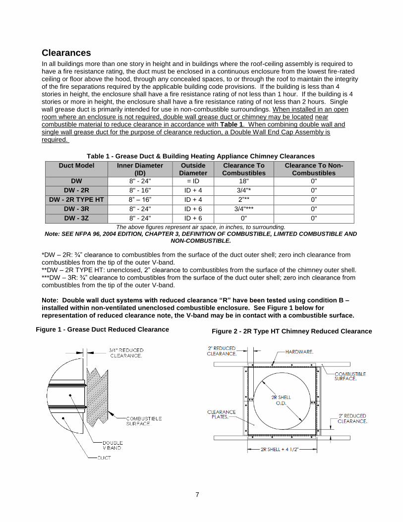
*DW – 2R: ¾” clearance to combustibles from the surface of the duct outer shell; zero inch clearance from combustibles from the tip of the outer V-band. **DW – 2R TYPE HT: unenclosed, 2” clearance to combustibles from the surface of the chimney outer shell. ***DW – 3R: ¾” clearance to combustibles from the surface of the duct outer shell; zero inch clearance from combustibles from the tip of the outer V-band. Note: Double wall duct systems with reduced clearance “R” have been tested using condition B – installed within non-ventilated unenclosed combustible enclosure. See Figure 1 below for representation of reduced clearance note, the V-band may be in contact with a combustible surface.
Figure 1 - Grease Duct Reduced Clearance Figure 2 - 2R Type HT Chimney Reduced Clearance
8
MECHANICAL
Joint Sealant The joint sealant used to seal all joint assemblies is a 3M product. 3M Fire Barrier 2000+ Silicone Sealant is a ready-to-use, gun-grade, one-component silicone elastomer that cures upon exposure to atmospheric humidity to form a flexible seal. 3M Fire Barrier 2000+ Silicone Sealant, when installed properly, will control the spread of fire before, during and after exposure to open flames. It will stop the spread of noxious gas, smoke and water, and maintain the integrity of fire rated assemblies and construction. All grease ducts must be liquid tight per NFPA 96. The following steps are to be used to ensure that this requirement is met. Model 2R Type HT chimney does not require joints to be sealed with the 3M Fire Barrier 2000+ Silicone Sealant per the listing report. Although 2R Type HT chimney does not require the joints to be sealed, it is recommended for commercial cooking appliances where grease is present.
NO SEALANT SUBSTITUTES MAY BE USED.
Sealant Features
1. Superior adhesion.
2. Capable of withstanding 2000°F + temperatures.
3. Class 25 sealant, per ASTM 920.
4. Re-enterable/repairable.
5. Provides up to 4-hours fire-rating.
6. Cures upon exposure to atmospheric humidity.
7. Working time 30 minutes.
8. Full cure time: 14 to 21 days.
9. Duct can be placed in operation 7 days after installation, prior to full cure.
10. Applied with a standard caulk gun.
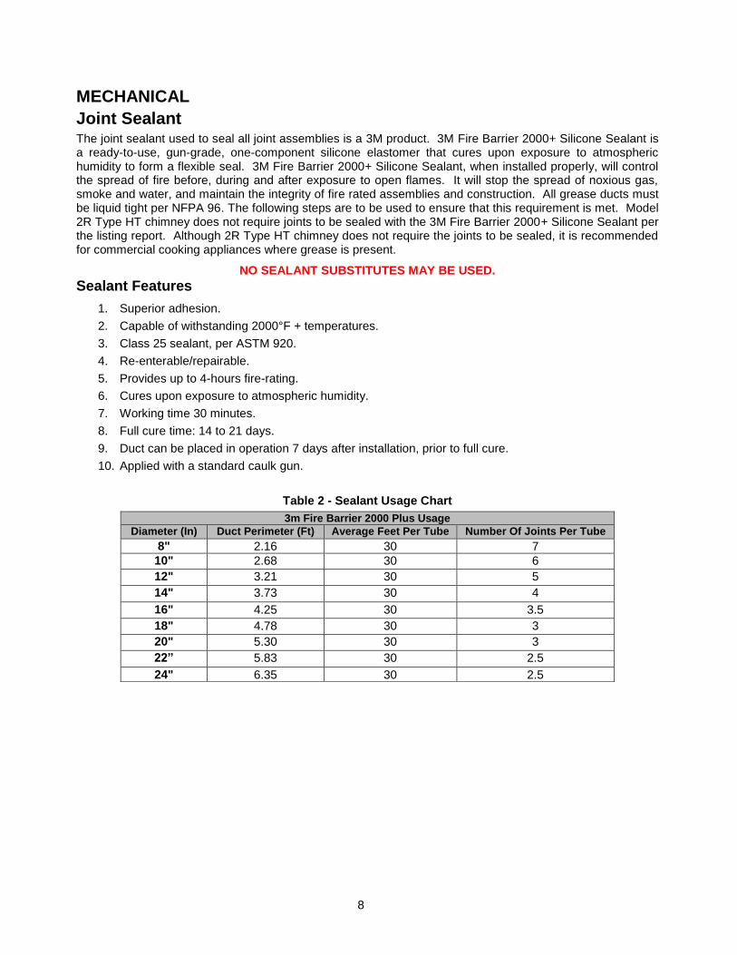
Table 2 - Sealant Usage Chart
3m Fire Barrier 2000 Plus Usage
Diameter (In) Duct Perimeter (Ft) Average Feet Per Tube Number Of Joints Per Tube
8" 2.16 30 7
10" 2.68 30 6
12" 3.21 30 5
14" 3.73 30 4
16" 4.25 30 3.5
18" 4.78 30 3
20" 5.30 30 3
22” 5.83 30 2.5
24" 6.35 30 2.5
9
Grease Duct & Chimney Joint Assembly All grease ducts are to be liquid tight per NFPA 96. The following steps are to be used to ensure that this requirement is met. Model 2R Type HT chimney does not require joints to be sealed with the 3M Fire Barrier 2000+ Silicone Sealant per the listing report. Although 2R Type HT chimney does not require the joints to be sealed, it is recommended for commercial cooking appliances where grease is present.
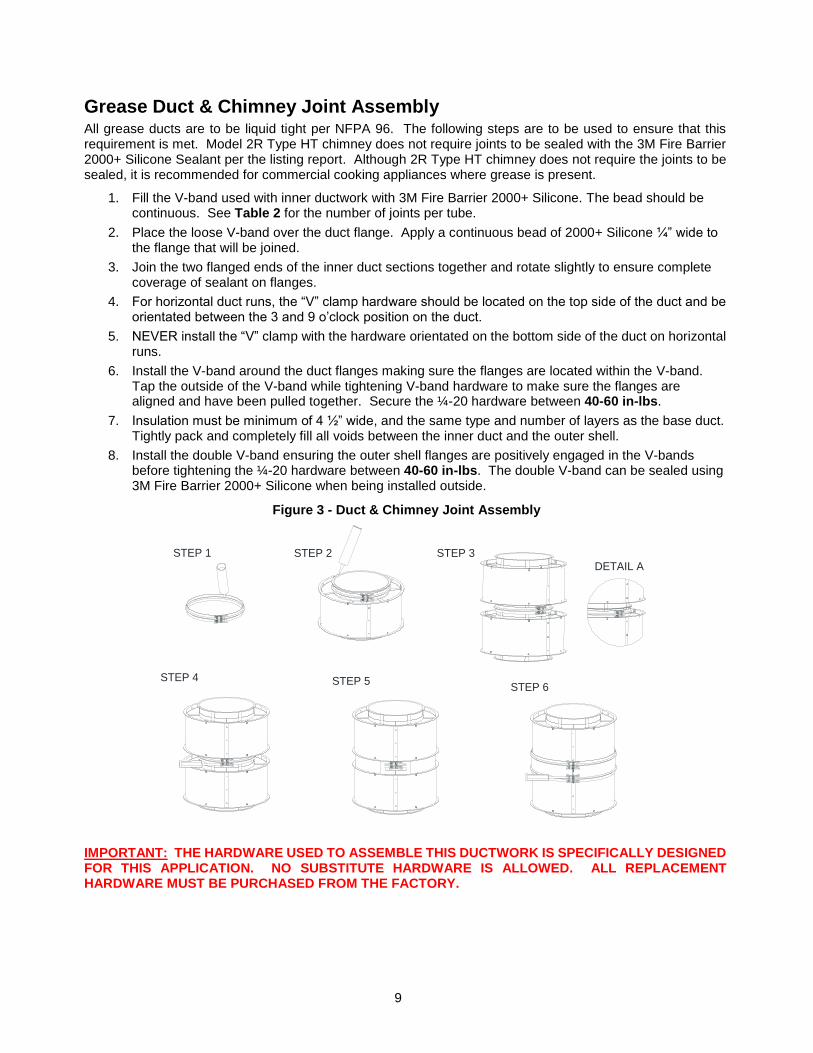
1. Fill the V-band used with inner ductwork with 3M Fire Barrier 2000+ Silicone. The bead should be continuous. See Table 2 for the number of joints per tube.
2. Place the loose V-band over the duct flange. Apply a continuous bead of 2000+ Silicone ¼” wide to the flange that will be joined.
3. Join the two flanged ends of the inner duct sections together and rotate slightly to ensure complete coverage of sealant on flanges.
4. For horizontal duct runs, the “V” clamp hardware should be located on the top side of the duct and be orientated between the 3 and 9 o’clock position on the duct.
5. NEVER install the “V” clamp with the hardware orientated on the bottom side of the duct on horizontal runs.
6. Install the V-band around the duct flanges making sure the flanges are located within the V-band. Tap the outside of the V-band while tightening V-band hardware to make sure the flanges are aligned and have been pulled together. Secure the ¼-20 hardware between 40-60 in-lbs.
7. Insulation must be minimum of 4 ½” wide, and the same type and number of layers as the base duct. Tightly pack and completely fill all voids between the inner duct and the outer shell.
8. Install the double V-band ensuring the outer shell flanges are positively engaged in the V-bands before tightening the ¼-20 hardware between 40-60 in-lbs. The double V-band can be sealed using 3M Fire Barrier 2000+ Silicone when being installed outside.
IMPORTANT: THE HARDWARE USED TO ASSEMBLE THIS DUCTWORK IS SPECIFICALLY DESIGNED FOR THIS APPLICATION. NO SUBSTITUTE HARDWARE IS ALLOWED. ALL REPLACEMENT HARDWARE MUST BE PURCHASED FROM THE FACTORY.
Figure 3 - Duct & Chimney Joint Assembly
STEP 2STEP 1 STEP 3
STEP 4 STEP 5STEP 6
DETAIL A
10
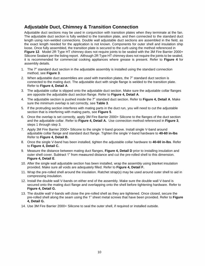
Adjustable Duct, Chimney & Transition Connection Adjustable duct sections may be used in conjunction with transition plates when they terminate at the fan. The adjustable duct section is fully welded to the transition plate, and then connected to the standard duct length using non-welded connections. Double wall adjustable duct sections are assembled in the field, as the exact length needed for the application is not known. Components for outer shell and insulation ship loose. Once fully assembled, the transition plate is secured to the curb using the method referenced in Figure 12. Model 2R Type HT chimney does not require joints to be sealed with the 3M Fire Barrier 2000+ Silicone Sealant per the listing report. Although 2R Type HT chimney does not require the joints to be sealed, it is recommended for commercial cooking appliances where grease is present. Refer to Figure 4 for assembly details.
1. The 7” standard duct section in the adjustable assembly is installed using the standard connection method, see Figure 3.
2. When adjustable duct assemblies are used with transition plates, the 7” standard duct section is connected to the mating duct. The adjustable duct with single flange is welded to the transition plate. Refer to Figure 4, Detail A.
3. The adjustable collar is slipped onto the adjustable duct section. Make sure the adjustable collar flanges are opposite the adjustable duct section flange. Refer to Figure 4, Detail A.
4. The adjustable section is pushed inside the 7” standard duct section. Refer to Figure 4, Detail A. Make sure the minimum overlap is set correctly, see Table 3.
5. If the protruding section interferes with mating parts in the duct run, you will need to cut the adjustable section that is interfering with mating parts, see Figure 5.
6. Once the overlap is set correctly, apply 3M Fire Barrier 2000+ Silicone to the flanges of the duct section and the adjustable collar. Refer to Figure 4, Detail A. Use connection method referenced in Figure 3, steps 1 through step 3.
7. Apply 3M Fire Barrier 2000+ Silicone to the single V-band groove. Install single V-band around adjustable collar flange and standard duct flange. Tighten the single V-band hardware to 40-60 in-lbs Refer to Figure 4, Detail B.
8. Once the single V-band has been installed, tighten the adjustable collar hardware to 40-60 in-lbs. Refer to Figure 4, Detail C.
9. Measure the distance between mating duct flanges, Figure 4, Detail D prior to installing insulation and outer shell cover. Subtract 1” from measured distance and cut the pre-rolled shell to this dimension. Figure 4, Detail E.
10. After the single wall adjustable section has been installed, wrap the assembly using blanket insulation provided. Make sure all voids are adequately filled. Refer to Figure 4, Detail F.
11. Wrap the pre-rolled shell around the insulation. Ratchet strap(s) may be used around outer shell to aid in compressing insulation.
12. Install the double wall V-bands on either end of the assembly. Make sure the double wall V-band is secured onto the mating duct flange and overlapping onto the shell before tightening hardware. Refer to Figure 4, Detail G.
13. The double wall V-bands will close the pre-rolled shell as they are tightened. Once closed, secure the pre-rolled shell along the seam using the 1” sheet metal screws that have been provided. Refer to Figure 4, Detail G.
14. Use 3M Fire Barrier 2000+ Silicone to seal the outer shell, if required or installed outside.
11
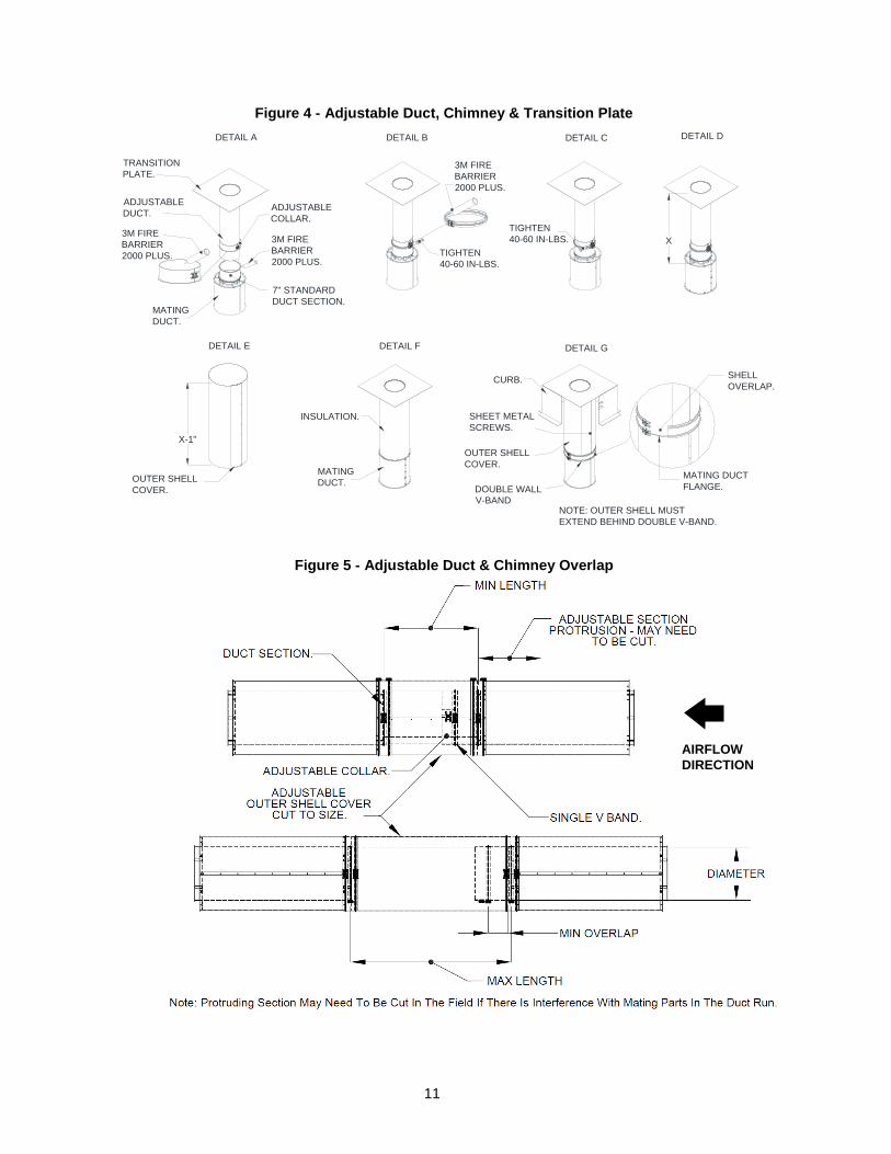
Figure 4 - Adjustable Duct, Chimney & Transition Plate
Figure 5 - Adjustable Duct & Chimney Overlap
AIRFLOW
DIRECTION
DETAIL A DETAIL B DETAIL C DETAIL D
DETAIL E DETAIL G
CURB.
TRANSITION
PLATE.
ADJUSTABLE
DUCT.
3M FIRE
BARRIER
2000 PLUS.
ADJUSTABLE
COLLAR.
3M FIRE
BARRIER
2000 PLUS.
7" STANDARD
DUCT SECTION.
3M FIRE
BARRIER
2000 PLUS.
TIGHTEN
40-60 IN-LBS.
TIGHTEN
40-60 IN-LBS.
SHEET METAL
SCREWS.
OUTER SHELL
COVER.
NOTE: OUTER SHELL MUST
EXTEND BEHIND DOUBLE V-BAND.
MATING DUCT
FLANGE.
MATING
DUCT.
X
X-1"
DETAIL F
OUTER SHELL
COVER. DOUBLE WALL
V-BAND
INSULATION.
MATING
DUCT.
SHELL
OVERLAP.
12
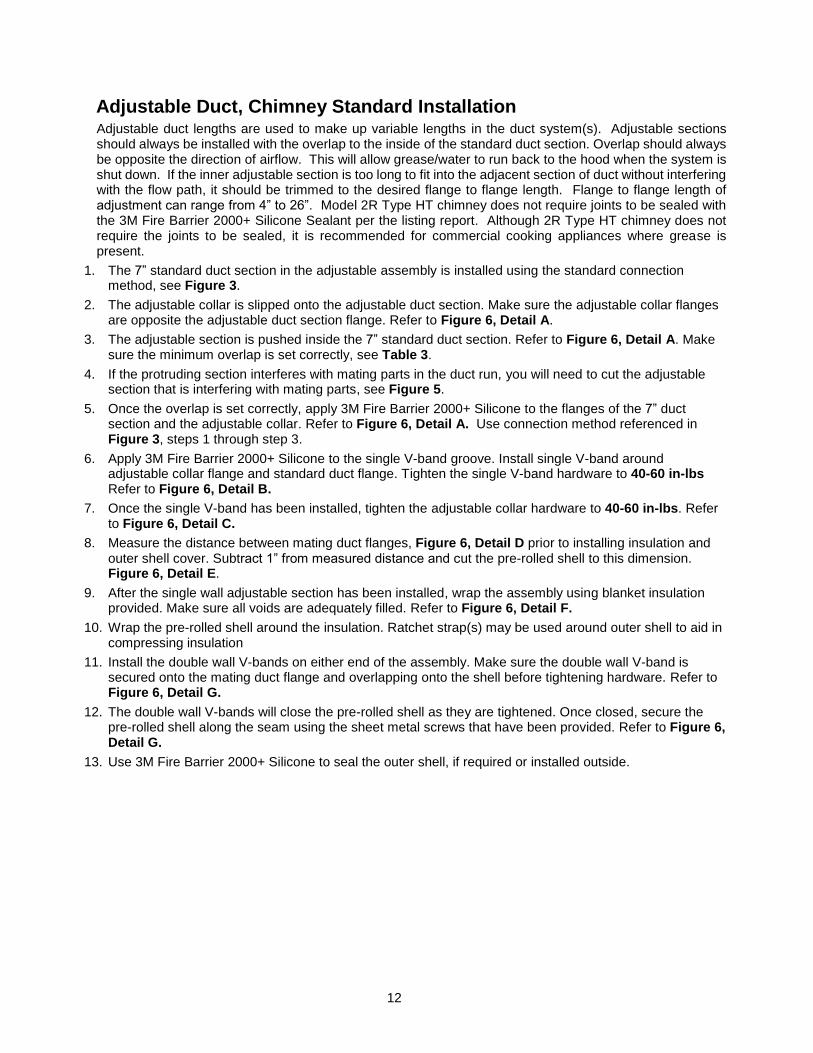
Adjustable Duct, Chimney Standard Installation Adjustable duct lengths are used to make up variable lengths in the duct system(s). Adjustable sections should always be installed with the overlap to the inside of the standard duct section. Overlap should always be opposite the direction of airflow. This will allow grease/water to run back to the hood when the system is shut down. If the inner adjustable section is too long to fit into the adjacent section of duct without interfering with the flow path, it should be trimmed to the desired flange to flange length. Flange to flange length of adjustment can range from 4” to 26”. Model 2R Type HT chimney does not require joints to be sealed with the 3M Fire Barrier 2000+ Silicone Sealant per the listing report. Although 2R Type HT chimney does not require the joints to be sealed, it is recommended for commercial cooking appliances where grease is present.
1. The 7” standard duct section in the adjustable assembly is installed using the standard connection method, see Figure 3.
2. The adjustable collar is slipped onto the adjustable duct section. Make sure the adjustable collar flanges are opposite the adjustable duct section flange. Refer to Figure 6, Detail A.
3. The adjustable section is pushed inside the 7” standard duct section. Refer to Figure 6, Detail A. Make sure the minimum overlap is set correctly, see Table 3.
4. If the protruding section interferes with mating parts in the duct run, you will need to cut the adjustable section that is interfering with mating parts, see Figure 5.
5. Once the overlap is set correctly, apply 3M Fire Barrier 2000+ Silicone to the flanges of the 7” duct section and the adjustable collar. Refer to Figure 6, Detail A. Use connection method referenced in Figure 3, steps 1 through step 3.
6. Apply 3M Fire Barrier 2000+ Silicone to the single V-band groove. Install single V-band around adjustable collar flange and standard duct flange. Tighten the single V-band hardware to 40-60 in-lbs Refer to Figure 6, Detail B.
7. Once the single V-band has been installed, tighten the adjustable collar hardware to 40-60 in-lbs. Refer to Figure 6, Detail C.
8. Measure the distance between mating duct flanges, Figure 6, Detail D prior to installing insulation and outer shell cover. Subtract 1” from measured distance and cut the pre-rolled shell to this dimension. Figure 6, Detail E.
9. After the single wall adjustable section has been installed, wrap the assembly using blanket insulation provided. Make sure all voids are adequately filled. Refer to Figure 6, Detail F.
10. Wrap the pre-rolled shell around the insulation. Ratchet strap(s) may be used around outer shell to aid in compressing insulation
11. Install the double wall V-bands on either end of the assembly. Make sure the double wall V-band is secured onto the mating duct flange and overlapping onto the shell before tightening hardware. Refer to Figure 6, Detail G.
12. The double wall V-bands will close the pre-rolled shell as they are tightened. Once closed, secure the pre-rolled shell along the seam using the sheet metal screws that have been provided. Refer to Figure 6, Detail G.
13. Use 3M Fire Barrier 2000+ Silicone to seal the outer shell, if required or installed outside.
13
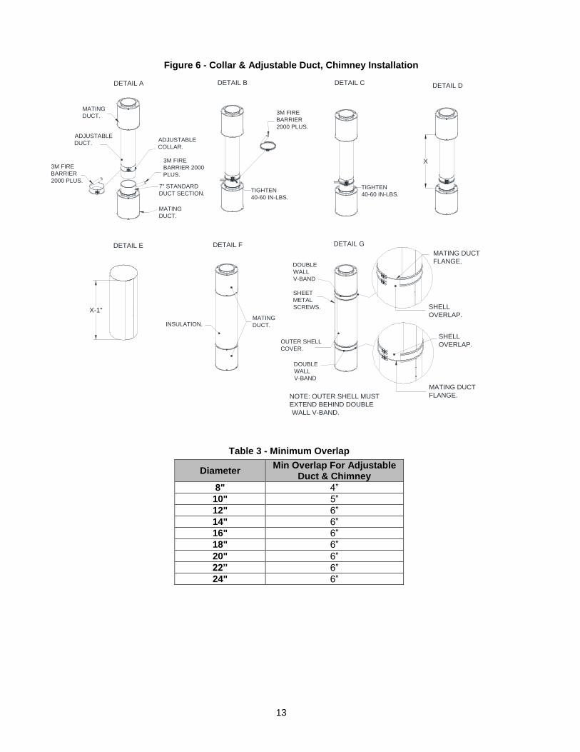
Table 3 - Minimum Overlap
Diameter Min Overlap For Adjustable
Duct & Chimney
8" 4”
10" 5”
12" 6”
14" 6”
16" 6”
18" 6”
20" 6”
22” 6”
24" 6”
Figure 6 - Collar & Adjustable Duct, Chimney Installation
X
X-1"
DETAIL A DETAIL B DETAIL C DETAIL D
DETAIL E DETAIL GDETAIL F
3M FIRE
BARRIER
2000 PLUS.
ADJUSTABLE
DUCT.ADJUSTABLE
COLLAR.
3M FIRE
BARRIER 2000
PLUS.
7" STANDARD
DUCT SECTION.
MATING
DUCT.
MATING
DUCT.
3M FIRE
BARRIER
2000 PLUS.
TIGHTEN
40-60 IN-LBS.
TIGHTEN
40-60 IN-LBS.
NOTE: OUTER SHELL MUST
EXTEND BEHIND DOUBLE
WALL V-BAND.
INSULATION.MATING
DUCT.
SHEET
METAL
SCREWS.
OUTER SHELL
COVER.
DOUBLE
WALL
V-BAND
DOUBLE
WALL
V-BAND
MATING DUCT
FLANGE.
MATING DUCT
FLANGE.
SHELL
OVERLAP.
SHELL
OVERLAP.
14
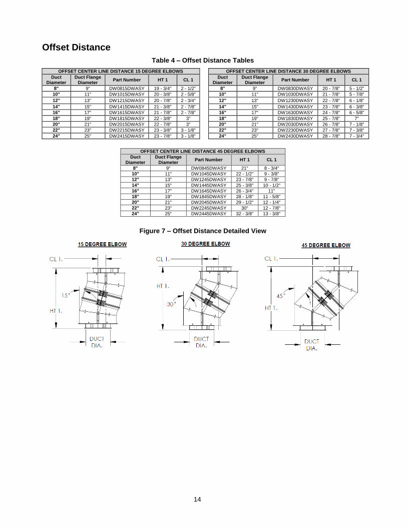
Offset Distance
Table 4 – Offset Distance Tables
OFFSET CENTER LINE DISTANCE 15 DEGREE ELBOWS OFFSET CENTER LINE DISTANCE 30 DEGREE ELBOWS
Duct Diameter
Duct Flange Diameter
Part Number HT 1 CL 1 Duct
Diameter Duct Flange
Diameter Part Number HT 1 CL 1
8" 9" DW0815DWASY 19 - 3/4" 2 - 1/2" 8" 9" DW0830DWASY 20 - 7/8" 5 - 1/2"
10" 11" DW1015DWASY 20 - 3/8" 2 - 5/8" 10" 11" DW1030DWASY 21 - 7/8" 5 - 7/8"
12" 13" DW1215DWASY 20 - 7/8" 2 - 3/4" 12" 13" DW1230DWASY 22 - 7/8" 6 - 1/8"
14" 15" DW1415DWASY 21 - 3/8" 2 - 7/8" 14" 15" DW1430DWASY 23 - 7/8" 6 - 3/8"
16" 17" DW1615DWASY 21 - 7/8" 2 - 7/8" 16" 17" DW1630DWASY 24 - 7/8" 6 - 5/8"
18" 19" DW1815DWASY 22 - 3/8" 3" 18" 19" DW1830DWASY 25 - 7/8" 7"
20" 21" DW2015DWASY 22 - 7/8" 3" 20" 21" DW2030DWASY 26 - 7/8" 7 - 1/8"
22" 23" DW2215DWASY 23 - 3/8" 3 - 1/8" 22" 23" DW2230DWASY 27 - 7/8" 7 - 3/8"
24" 25" DW2415DWASY 23 - 7/8" 3 - 1/8" 24" 25" DW2430DWASY 28 - 7/8" 7 - 3/4"
OFFSET CENTER LINE DISTANCE 45 DEGREE ELBOWS
Duct Diameter
Duct Flange Diameter
Part Number HT 1 CL 1
8" 9" DW0845DWASY 21" 8 - 3/4"
10" 11" DW1045DWASY 22 - 1/2" 9 - 3/8"
12" 13" DW1245DWASY 23 - 7/8" 9 - 7/8"
14" 15" DW1445DWASY 25 - 3/8" 10 - 1/2"
16" 17" DW1645DWASY 26 - 3/4" 11"
18" 19" DW1845DWASY 28 - 1/8" 11 - 5/8"
20" 21" DW2045DWASY 29 - 1/2" 12 - 1/4"
22" 23" DW2245DWASY 30" 12 - 7/8"
24" 25" DW2445DWASY 32 - 3/8" 13 - 3/8"
Figure 7 – Offset Distance Detailed View
15
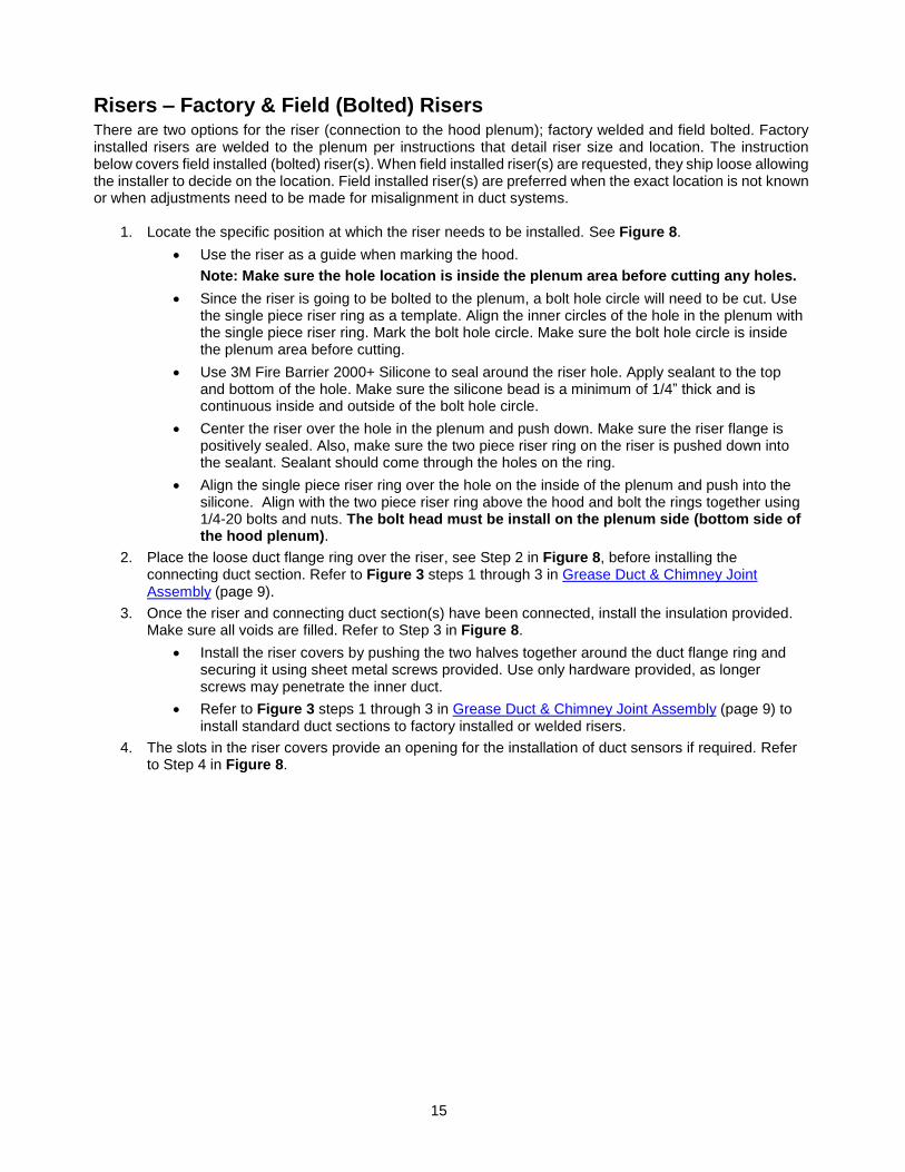
Risers – Factory & Field (Bolted) Risers There are two options for the riser (connection to the hood plenum); factory welded and field bolted. Factory installed risers are welded to the plenum per instructions that detail riser size and location. The instruction below covers field installed (bolted) riser(s). When field installed riser(s) are requested, they ship loose allowing the installer to decide on the location. Field installed riser(s) are preferred when the exact location is not known or when adjustments need to be made for misalignment in duct systems.
1. Locate the specific position at which the riser needs to be installed. See Figure 8.
Use the riser as a guide when marking the hood.
Note: Make sure the hole location is inside the plenum area before cutting any holes.
Since the riser is going to be bolted to the plenum, a bolt hole circle will need to be cut. Use the single piece riser ring as a template. Align the inner circles of the hole in the plenum with the single piece riser ring. Mark the bolt hole circle. Make sure the bolt hole circle is inside the plenum area before cutting.
Use 3M Fire Barrier 2000+ Silicone to seal around the riser hole. Apply sealant to the top and bottom of the hole. Make sure the silicone bead is a minimum of 1/4” thick and is continuous inside and outside of the bolt hole circle.
Center the riser over the hole in the plenum and push down. Make sure the riser flange is positively sealed. Also, make sure the two piece riser ring on the riser is pushed down into the sealant. Sealant should come through the holes on the ring.
Align the single piece riser ring over the hole on the inside of the plenum and push into the silicone. Align with the two piece riser ring above the hood and bolt the rings together using 1/4-20 bolts and nuts. The bolt head must be install on the plenum side (bottom side of the hood plenum).
2. Place the loose duct flange ring over the riser, see Step 2 in Figure 8, before installing the connecting duct section. Refer to Figure 3 steps 1 through 3 in Grease Duct & Chimney Joint Assembly (page 9).
3. Once the riser and connecting duct section(s) have been connected, install the insulation provided. Make sure all voids are filled. Refer to Step 3 in Figure 8.
Install the riser covers by pushing the two halves together around the duct flange ring and securing it using sheet metal screws provided. Use only hardware provided, as longer screws may penetrate the inner duct.
Refer to Figure 3 steps 1 through 3 in Grease Duct & Chimney Joint Assembly (page 9) to install standard duct sections to factory installed or welded risers.
4. The slots in the riser covers provide an opening for the installation of duct sensors if required. Refer to Step 4 in Figure 8.
16
Figure 8 - Field Installed Riser (Bolted)
V BAND.RISER
COVER.
INSULATION.
SHEET METAL
SCREWS.RISER COVER.
STEP 3
HOLE FOR
DUCT STAT
INSTALLATION.
STEP 4
DOUBLE WALL
DUCT.
V BAND.
DUCT FLANGE
RING.
STEP 2
TWO PIECE RISER RING.
NOTE: MAKE SURE TABS
ARE ON TOP.
1/4-20 BOLT.SINGLE PIECE
RISER RING.
HOOD TOP.
3M FIRE BARRIER 2000 PLUS.
NOTE: SEAL TOP AND BOTTOM.
1/4-20 NUT.
STEP 1
RISER.
TWO PIECE
RISER RING
17
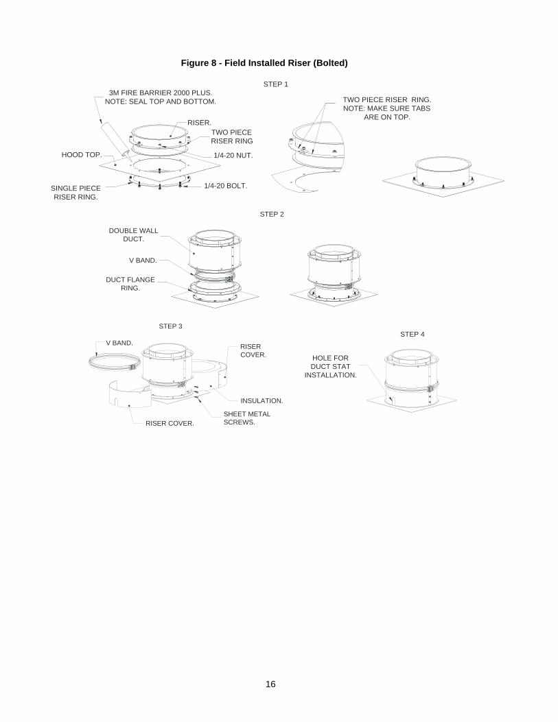
Duct Drains Drains are used to provide a point at which low points in the duct system can be drained. Condensation and low lying water left over from duct cleaning can be drained easily with the installation of a ball valve drain. Drains are designed to aid in duct cleaning and can be used to drain grease into an approved grease collection reservoir. Drains can be hard piped to an approved grease collection reservoir, remove the cap and connect to the 1-1/2” NPT threads (see Figure 9 for details).
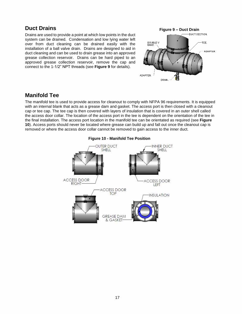
Manifold Tee The manifold tee is used to provide access for cleanout to comply with NFPA 96 requirements. It is equipped with an internal blank that acts as a grease dam and gasket. The access port is then closed with a cleanout cap or tee cap. The tee cap is then covered with layers of insulation that is covered in an outer shell called the access door collar. The location of the access port in the tee is dependent on the orientation of the tee in the final installation. The access port location in the manifold tee can be orientated as required (see Figure 10). Access ports should never be located where grease can build up and fall out once the cleanout cap is removed or where the access door collar cannot be removed to gain access to the inner duct.
Figure 9 – Duct Drain
Figure 10 - Manifold Tee Position
18
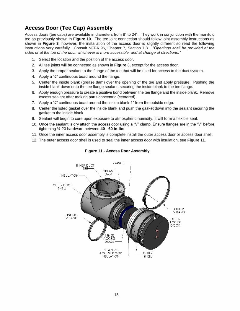
Access Door (Tee Cap) Assembly Access doors (tee caps) are available in diameters from 8” to 24”. They work in conjunction with the manifold tee as previously shown in Figure 10. The tee joint connection should follow joint assembly instructions as shown in Figure 3; however, the installation of the access door is slightly different so read the following instructions very carefully. Consult NFPA 96, Chapter 7, Section 7.3.1 “Openings shall be provided at the sides or at the top of the duct, whichever is more accessible, and at change of directions.”
1. Select the location and the position of the access door.
2. All tee joints will be connected as shown in Figure 3, except for the access door.
3. Apply the proper sealant to the flange of the tee that will be used for access to the duct system.
4. Apply a ¼” continuous bead around the flange.
5. Center the inside blank (grease dam) over the opening of the tee and apply pressure. Pushing the inside blank down onto the tee flange sealant, securing the inside blank to the tee flange.
6. Apply enough pressure to create a positive bond between the tee flange and the inside blank. Remove excess sealant after making parts concentric (centered).
7. Apply a ¼” continuous bead around the inside blank 1” from the outside edge.
8. Center the listed gasket over the inside blank and push the gasket down into the sealant securing the gasket to the inside blank.
9. Sealant will begin to cure upon exposure to atmospheric humidity. It will form a flexible seal.
10. Once the sealant is dry attach the access door using a “V” clamp. Ensure flanges are in the “V” before tightening ¼-20 hardware between 40 - 60 in-lbs.
11. Once the inner access door assembly is complete install the outer access door or access door shell.
12. The outer access door shell is used to seal the inner access door with insulation, see Figure 11.
Figure 11 - Access Door Assembly
19
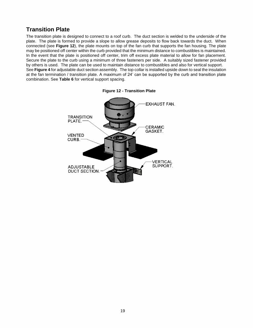
Transition Plate The transition plate is designed to connect to a roof curb. The duct section is welded to the underside of the plate. The plate is formed to provide a slope to allow grease deposits to flow back towards the duct. When connected (see Figure 12), the plate mounts on top of the fan curb that supports the fan housing. The plate may be positioned off center within the curb provided that the minimum distance to combustibles is maintained. In the event that the plate is positioned off center, trim off excess plate material to allow for fan placement. Secure the plate to the curb using a minimum of three fasteners per side. A suitably sized fastener provided by others is used. The plate can be used to maintain distance to combustibles and also for vertical support. See Figure 4 for adjustable duct section assembly. The top collar is installed upside down to seal the insulation at the fan termination / transition plate. A maximum of 24’ can be supported by the curb and transition plate combination. See Table 6 for vertical support spacing.
Figure 12 - Transition Plate
20
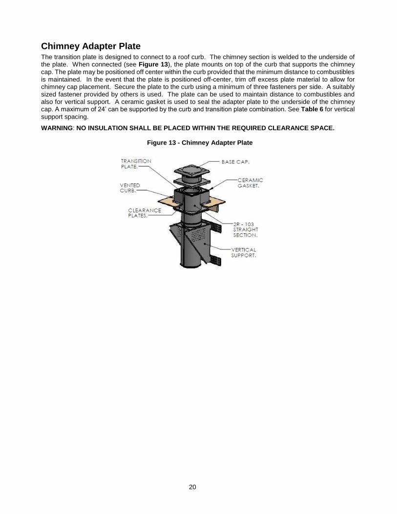
Chimney Adapter Plate The transition plate is designed to connect to a roof curb. The chimney section is welded to the underside of the plate. When connected (see Figure 13), the plate mounts on top of the curb that supports the chimney cap. The plate may be positioned off center within the curb provided that the minimum distance to combustibles is maintained. In the event that the plate is positioned off-center, trim off excess plate material to allow for chimney cap placement. Secure the plate to the curb using a minimum of three fasteners per side. A suitably sized fastener provided by others is used. The plate can be used to maintain distance to combustibles and also for vertical support. A ceramic gasket is used to seal the adapter plate to the underside of the chimney cap. A maximum of 24’ can be supported by the curb and transition plate combination. See Table 6 for vertical support spacing.
WARNING: NO INSULATION SHALL BE PLACED WITHIN THE REQUIRED CLEARANCE SPACE.
Figure 13 - Chimney Adapter Plate
21
Prevention of Grease Accumulation in Horizontal Grease Duct In some areas the local authority will require horizontal duct runs to be sloped. The duct referenced in this manual is listed, 1/16” per foot slope for horizontal runs less than 75 feet. For installations with horizontal runs greater than 75 feet, the duct referenced in this manual is listed, 3/16” per foot slope. In such cases, a short “Slope Transition” section is available from the factory. For correct installation, two slope transitions are generally required - one at the beginning and end of the horizontal duct run. Consult with local code authorities if unsure about local requirements. Offset collars have been designed to meet the above specification. The collar is used in conjunction with other accessories such as tees and elbows to maintain the above listed slope in horizontal duct runs. The “V” clamp hardware should be located on the top side of the duct and be orientated between the 3 and 9 o’clock position on the duct. Never install the “V” clamp with the hardware orientated on the bottom side of the duct on horizontal runs.
Alignment & Bracing of Grease Duct Grease duct has the characteristics of a continuous stainless steel pipe and it will expand and contract along its entire length with changes in temperature. For this reason, conventional methods of attaching guides and braces to the outer wall of the grease duct cannot be used. Correctly installed support rings, saddles and wall guide assemblies will serve to keep the duct aligned, provide for adequate resistance to lateral loads and allow the free axial expansion and contraction movement. A simplified rule for duct expansion is that the axial growth will be approximately 1 inch per 100 feet of pipe length for each 100 degrees Fahrenheit the exhaust vapor temperature is above the surrounding air temperature.
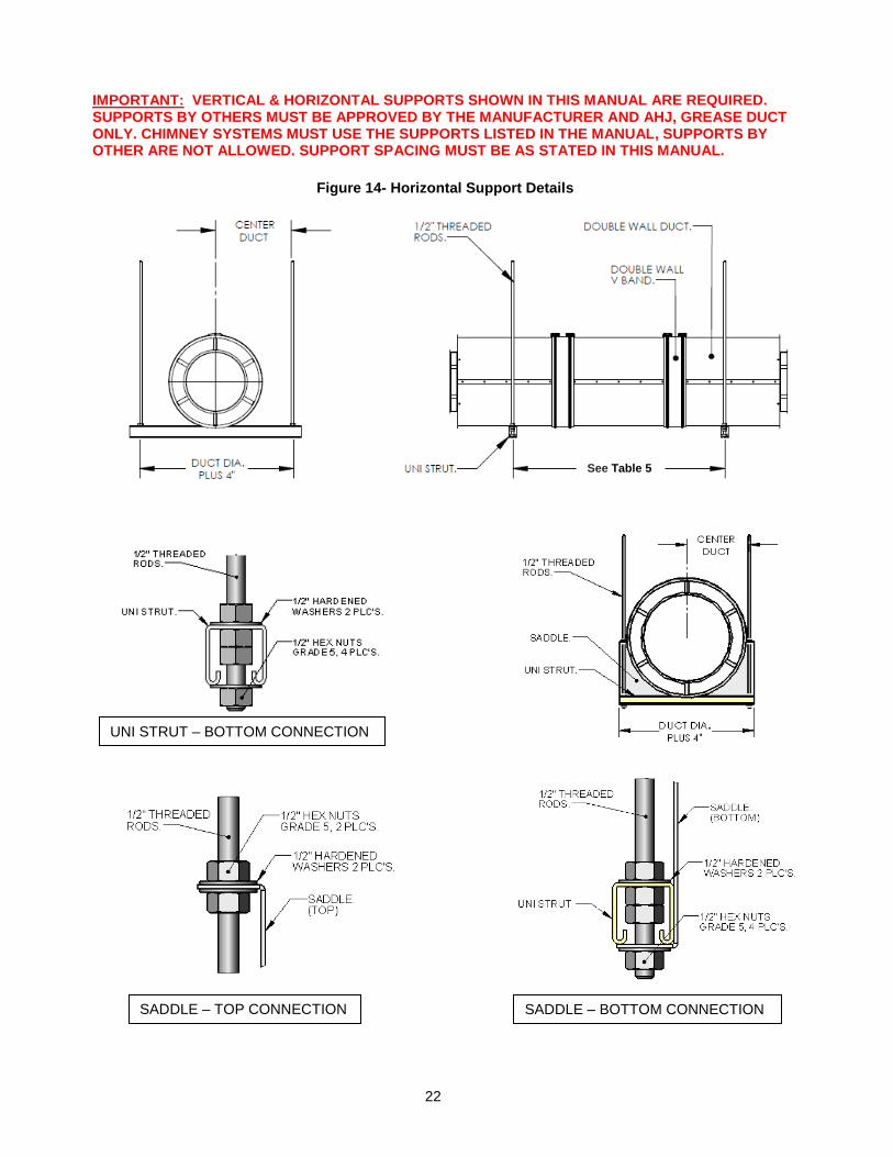
Horizontal Support & Support Spacing
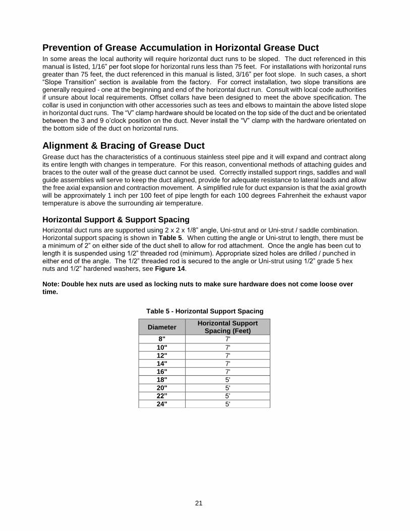
Horizontal duct runs are supported using 2 x 2 x 1/8” angle, Uni-strut and or Uni-strut / saddle combination. Horizontal support spacing is shown in Table 5. When cutting the angle or Uni-strut to length, there must be a minimum of 2” on either side of the duct shell to allow for rod attachment. Once the angle has been cut to length it is suspended using 1/2” threaded rod (minimum). Appropriate sized holes are drilled / punched in either end of the angle. The 1/2” threaded rod is secured to the angle or Uni-strut using 1/2” grade 5 hex nuts and 1/2” hardened washers, see Figure 14. Note: Double hex nuts are used as locking nuts to make sure hardware does not come loose over time.
Diameter Horizontal Support
Spacing (Feet)
8" 7'
10" 7'
12" 7'
14" 7'
16" 7'
18" 5'
20" 5'
22” 5’
24" 5'
Table 5 - Horizontal Support Spacing
22
IMPORTANT: VERTICAL & HORIZONTAL SUPPORTS SHOWN IN THIS MANUAL ARE REQUIRED. SUPPORTS BY OTHERS MUST BE APPROVED BY THE MANUFACTURER AND AHJ, GREASE DUCT ONLY. CHIMNEY SYSTEMS MUST USE THE SUPPORTS LISTED IN THE MANUAL, SUPPORTS BY OTHER ARE NOT ALLOWED. SUPPORT SPACING MUST BE AS STATED IN THIS MANUAL.
Figure 14- Horizontal Support Details
SADDLE – TOP CONNECTION SADDLE – BOTTOM CONNECTION
UNI STRUT – BOTTOM CONNECTION
See Table 5
23
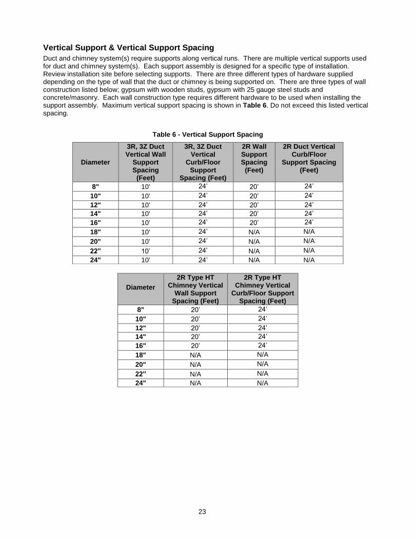
Vertical Support & Vertical Support Spacing
Duct and chimney system(s) require supports along vertical runs. There are multiple vertical supports used for duct and chimney system(s). Each support assembly is designed for a specific type of installation. Review installation site before selecting supports. There are three different types of hardware supplied depending on the type of wall that the duct or chimney is being supported on. There are three types of wall construction listed below; gypsum with wooden studs, gypsum with 25 gauge steel studs and concrete/masonry. Each wall construction type requires different hardware to be used when installing the support assembly. Maximum vertical support spacing is shown in Table 6. Do not exceed this listed vertical spacing.
Table 6 - Vertical Support Spacing
Diameter
3R, 3Z Duct Vertical Wall
Support Spacing
(Feet)
3R, 3Z Duct Vertical
Curb/Floor Support
Spacing (Feet)
2R Wall Support Spacing
(Feet)
2R Duct Vertical Curb/Floor
Support Spacing (Feet)
8" 10' 24’ 20’ 24’
10" 10' 24’ 20’ 24’
12" 10' 24’ 20’ 24’
14" 10' 24’ 20’ 24’
16" 10' 24’ 20’ 24’
18" 10' 24’ N/A N/A
20" 10' 24’ N/A N/A
22” 10’ 24’ N/A N/A
24" 10' 24’ N/A N/A
Diameter
2R Type HT Chimney Vertical
Wall Support Spacing (Feet)
2R Type HT Chimney Vertical
Curb/Floor Support Spacing (Feet)
8" 20’ 24’
10" 20’ 24’
12" 20’ 24’
14" 20’ 24’
16" 20’ 24’
18" N/A N/A
20" N/A N/A
22” N/A N/A
24" N/A N/A
24
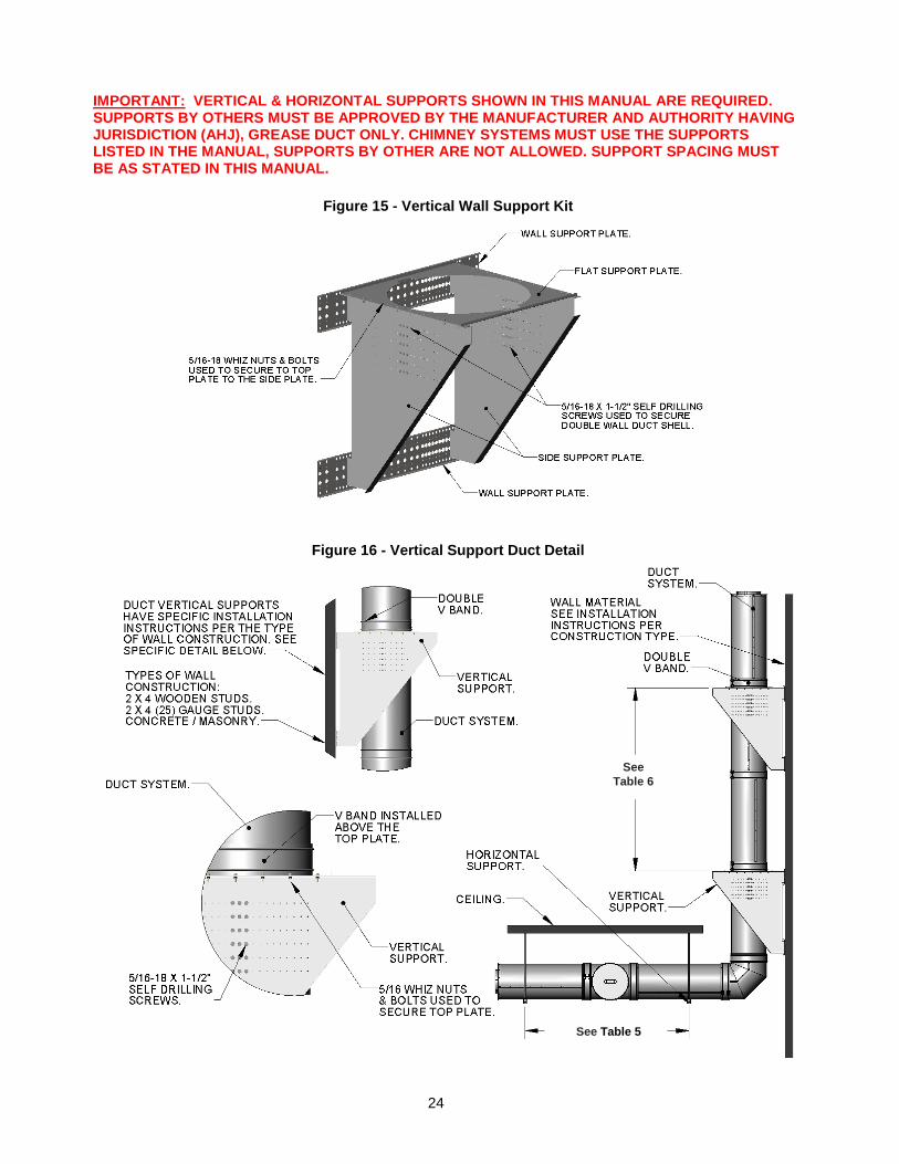
IMPORTANT: VERTICAL & HORIZONTAL SUPPORTS SHOWN IN THIS MANUAL ARE REQUIRED. SUPPORTS BY OTHERS MUST BE APPROVED BY THE MANUFACTURER AND AUTHORITY HAVING JURISDICTION (AHJ), GREASE DUCT ONLY. CHIMNEY SYSTEMS MUST USE THE SUPPORTS LISTED IN THE MANUAL, SUPPORTS BY OTHER ARE NOT ALLOWED. SUPPORT SPACING MUST BE AS STATED IN THIS MANUAL.
Figure 15 - Vertical Wall Support Kit
Figure 16 - Vertical Support Duct Detail
See
Table 6
See Table 5
25
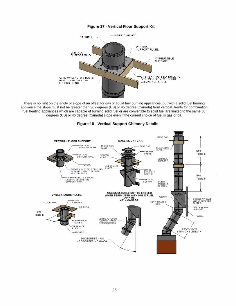
Figure 18 - Vertical Support Chimney Details
There is no limit on the angle or slope of an offset for gas or liquid fuel burning appliances, but with a solid fuel burning appliance the slope must not be greater than 30 degrees (US) or 45 degree (Canada) from vertical. Vents for combination fuel heating appliances which are capable of burning solid fuel or are convertible to solid fuel are limited to the same 30
degrees (US) or 45 degree (Canada) slope even if the current choice of fuel is gas or oil.
Figure 17 - Vertical Floor Support Kit
See Table 8
See Table 6
See Table 6
26
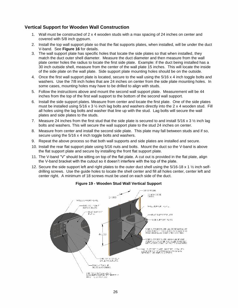
Vertical Support for Wooden Wall Construction
1. Wall must be constructed of 2 x 4 wooden studs with a max spacing of 24 inches on center and covered with 5/8 inch gypsum.
2. Install the top wall support plate so that the flat supports plates, when installed, will be under the duct V-band. See Figure 16 for details.
3. The wall support plate has specific holes that locate the side plates so that when installed, they match the duct outer shell diameter. Measure the duct diameter and then measure from the wall plate center holes the radius to locate the first side plate. Example: if the duct being installed has a 30 inch outside shell, measure from the center of the wall plate 15 inches. This will locate the inside of the side plate on the wall plate. Side support plate mounting holes should be on the outside.
4. Once the first wall support plate is located, secure to the wall using the 5/16 x 4 inch toggle bolts and washers. Use the 7/8 inch holes that are 24 inches on center from the side plate mounting holes. In some cases, mounting holes may have to be drilled to align with studs.
5. Follow the instructions above and mount the second wall support plate. Measurement will be 44 inches from the top of the first wall support to the bottom of the second wall support.
6. Install the side support plates. Measure from center and locate the first plate. One of the side plates must be installed using 5/16 x 3 ½ inch lag bolts and washers directly into the 2 x 4 wooden stud. Fill all holes using the lag bolts and washer that line up with the stud. Lag bolts will secure the wall plates and side plates to the studs.
7. Measure 24 inches from the first stud that the side plate is secured to and install 5/16 x 3 ½ inch lag bolts and washers. This will secure the wall support plate to the stud 24 inches on center.
8. Measure from center and install the second side plate. This plate may fall between studs and if so, secure using the 5/16 x 4 inch toggle bolts and washers.
9. Repeat the above process so that both wall supports and side plates are installed and secure.
10. Install the rear flat support plate using 5/16 nuts and bolts. Mount the duct so the V-band is above the flat support plate and secure by installing the front flat support plate.
11. The V-band “V” should be sitting on top of the flat plate. A cut out is provided in the flat plate, align the V-band bracket with the cutout so it doesn’t interfere with the top of the plate.
12. Secure the side support left and right plates to the outer duct shell using the 5/16-18 x 1 ½ inch self-drilling screws. Use the guide holes to locate the shell center and fill all holes center, center left and center right. A minimum of 18 screws must be used on each side of the duct.
Figure 19 - Wooden Stud Wall Vertical Support
27
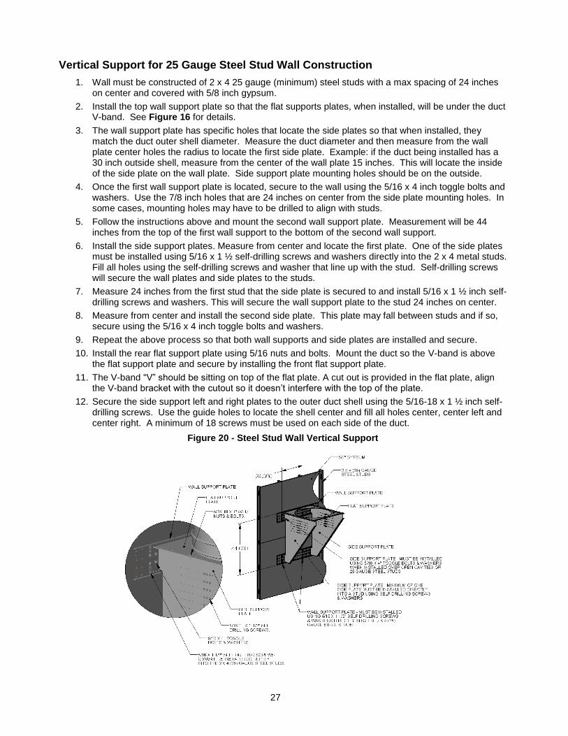
Vertical Support for 25 Gauge Steel Stud Wall Construction
1. Wall must be constructed of 2 x 4 25 gauge (minimum) steel studs with a max spacing of 24 inches on center and covered with 5/8 inch gypsum.
2. Install the top wall support plate so that the flat supports plates, when installed, will be under the duct V-band. See Figure 16 for details.
3. The wall support plate has specific holes that locate the side plates so that when installed, they match the duct outer shell diameter. Measure the duct diameter and then measure from the wall plate center holes the radius to locate the first side plate. Example: if the duct being installed has a 30 inch outside shell, measure from the center of the wall plate 15 inches. This will locate the inside of the side plate on the wall plate. Side support plate mounting holes should be on the outside.
4. Once the first wall support plate is located, secure to the wall using the 5/16 x 4 inch toggle bolts and washers. Use the 7/8 inch holes that are 24 inches on center from the side plate mounting holes. In some cases, mounting holes may have to be drilled to align with studs.
5. Follow the instructions above and mount the second wall support plate. Measurement will be 44 inches from the top of the first wall support to the bottom of the second wall support.
6. Install the side support plates. Measure from center and locate the first plate. One of the side plates must be installed using 5/16 x 1 ½ self-drilling screws and washers directly into the 2 x 4 metal studs. Fill all holes using the self-drilling screws and washer that line up with the stud. Self-drilling screws will secure the wall plates and side plates to the studs.
7. Measure 24 inches from the first stud that the side plate is secured to and install 5/16 x 1 ½ inch self-drilling screws and washers. This will secure the wall support plate to the stud 24 inches on center.
8. Measure from center and install the second side plate. This plate may fall between studs and if so, secure using the 5/16 x 4 inch toggle bolts and washers.
9. Repeat the above process so that both wall supports and side plates are installed and secure.
10. Install the rear flat support plate using 5/16 nuts and bolts. Mount the duct so the V-band is above the flat support plate and secure by installing the front flat support plate.
11. The V-band “V” should be sitting on top of the flat plate. A cut out is provided in the flat plate, align the V-band bracket with the cutout so it doesn’t interfere with the top of the plate.
12. Secure the side support left and right plates to the outer duct shell using the 5/16-18 x 1 ½ inch self-drilling screws. Use the guide holes to locate the shell center and fill all holes center, center left and center right. A minimum of 18 screws must be used on each side of the duct.
Figure 20 - Steel Stud Wall Vertical Support
28
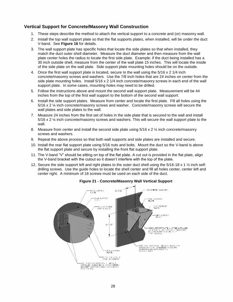
Vertical Support for Concrete/Masonry Wall Construction
1. These steps describe the method to attach the vertical support to a concrete and (or) masonry wall.
2. Install the top wall support plate so that the flat supports plates, when installed, will be under the duct V-band. See Figure 16 for details.
3. The wall support plate has specific holes that locate the side plates so that when installed, they match the duct outer shell diameter. Measure the duct diameter and then measure from the wall plate center holes the radius to locate the first side plate. Example: if the duct being installed has a 30 inch outside shell, measure from the center of the wall plate 15 inches. This will locate the inside of the side plate on the wall plate. Side support plate mounting holes should be on the outside.
4. Once the first wall support plate is located, secure to the wall using the 5/16 x 2 1/4 inch concrete/masonry screws and washers. Use the 7/8 inch holes that are 24 inches on center from the side plate mounting holes. Install 5/16 x 2 1/4 inch concrete/masonry screws in each end of the wall support plate. In some cases, mounting holes may need to be drilled.
5. Follow the instructions above and mount the second wall support plate. Measurement will be 44 inches from the top of the first wall support to the bottom of the second wall support.
6. Install the side support plates. Measure from center and locate the first plate. Fill all holes using the 5/16 x 2 ¼ inch concrete/masonry screws and washer. Concrete/masonry screws will secure the wall plates and side plates to the wall.
7. Measure 24 inches from the first set of holes in the side plate that is secured to the wall and install 5/16 x 2 ¼ inch concrete/masonry screws and washers. This will secure the wall support plate to the wall.
8. Measure from center and install the second side plate using 5/16 x 2 ¼ inch concrete/masonry screws and washers.
9. Repeat the above process so that both wall supports and side plates are installed and secure.
10. Install the rear flat support plate using 5/16 nuts and bolts. Mount the duct so the V-band is above the flat support plate and secure by installing the front flat support plate.
11. The V-band “V” should be sitting on top of the flat plate. A cut out is provided in the flat plate, align the V-band bracket with the cutout so it doesn’t interfere with the top of the plate.
12. Secure the side support left and right plates to the outer duct shell using the 5/16-18 x 1 ½ inch self-drilling screws. Use the guide holes to locate the shell center and fill all holes center, center left and center right. A minimum of 18 screws must be used on each side of the duct.
Figure 21 - Concrete/Masonry Wall Vertical Support
29
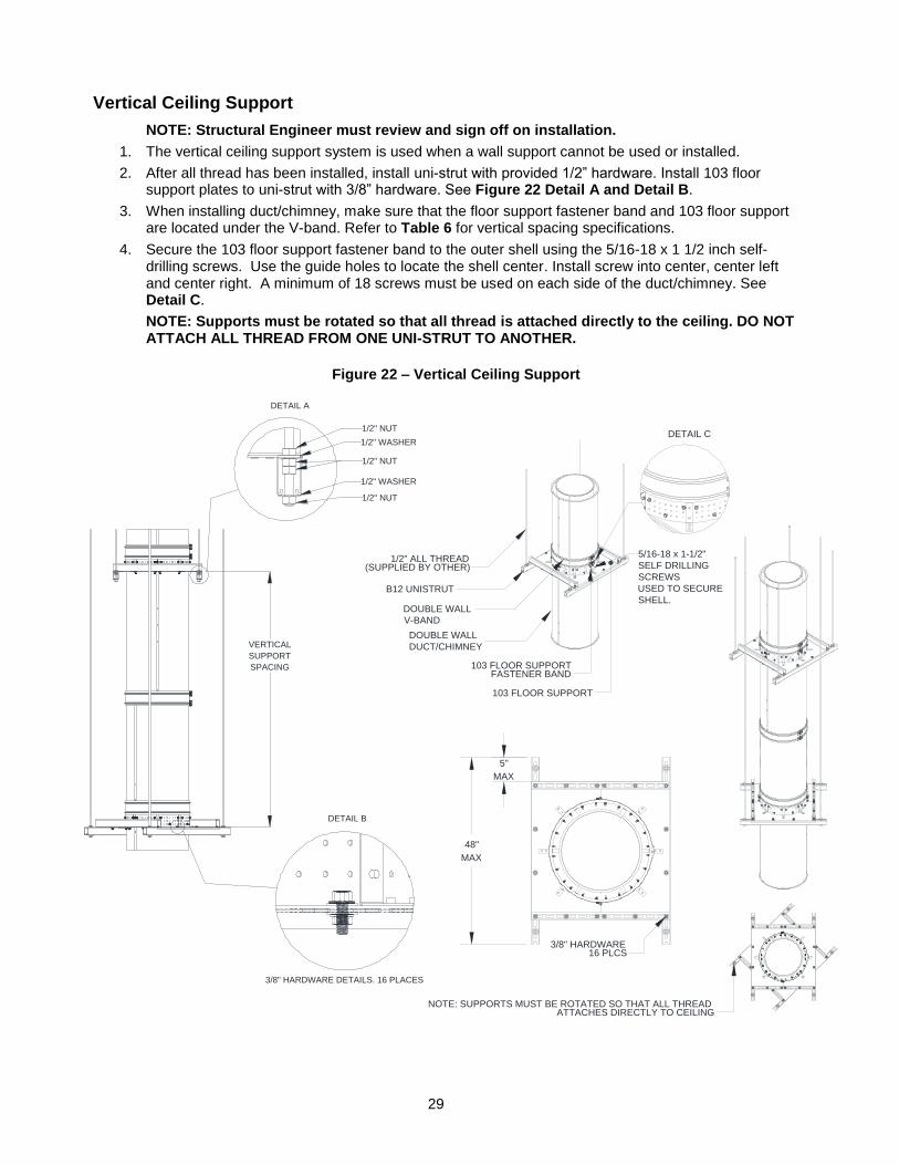
Vertical Ceiling Support
NOTE: Structural Engineer must review and sign off on installation.
1. The vertical ceiling support system is used when a wall support cannot be used or installed.
2. After all thread has been installed, install uni-strut with provided 1/2” hardware. Install 103 floor support plates to uni-strut with 3/8” hardware. See Figure 22 Detail A and Detail B.
3. When installing duct/chimney, make sure that the floor support fastener band and 103 floor support are located under the V-band. Refer to Table 6 for vertical spacing specifications.
4. Secure the 103 floor support fastener band to the outer shell using the 5/16-18 x 1 1/2 inch self-drilling screws. Use the guide holes to locate the shell center. Install screw into center, center left and center right. A minimum of 18 screws must be used on each side of the duct/chimney. See Detail C.
NOTE: Supports must be rotated so that all thread is attached directly to the ceiling. DO NOT ATTACH ALL THREAD FROM ONE UNI-STRUT TO ANOTHER.
DOUBLE WALL
DUCT/CHIMNEY
B12 UNISTRUT
1/2" ALL THREAD(SUPPLIED BY OTHER)
DOUBLE WALL
V-BAND
103 FLOOR SUPPORT
103 FLOOR SUPPORTFASTENER BAND
NOTE: SUPPORTS MUST BE ROTATED SO THAT ALL THREADATTACHES DIRECTLY TO CEILING
5"
MAX
48"
MAX
3/8" HARDWARE16 PLCS
5/16-18 x 1-1/2"
SELF DRILLING
SCREWS
USED TO SECURE
SHELL.
DETAIL C
VERTICAL
SUPPORT
SPACING
3/8" HARDWARE DETAILS. 16 PLACES
1/2" NUT
1/2" WASHER
1/2" NUT
1/2" WASHER
1/2" NUT
DETAIL A
DETAIL B
Figure 22 – Vertical Ceiling Support
30
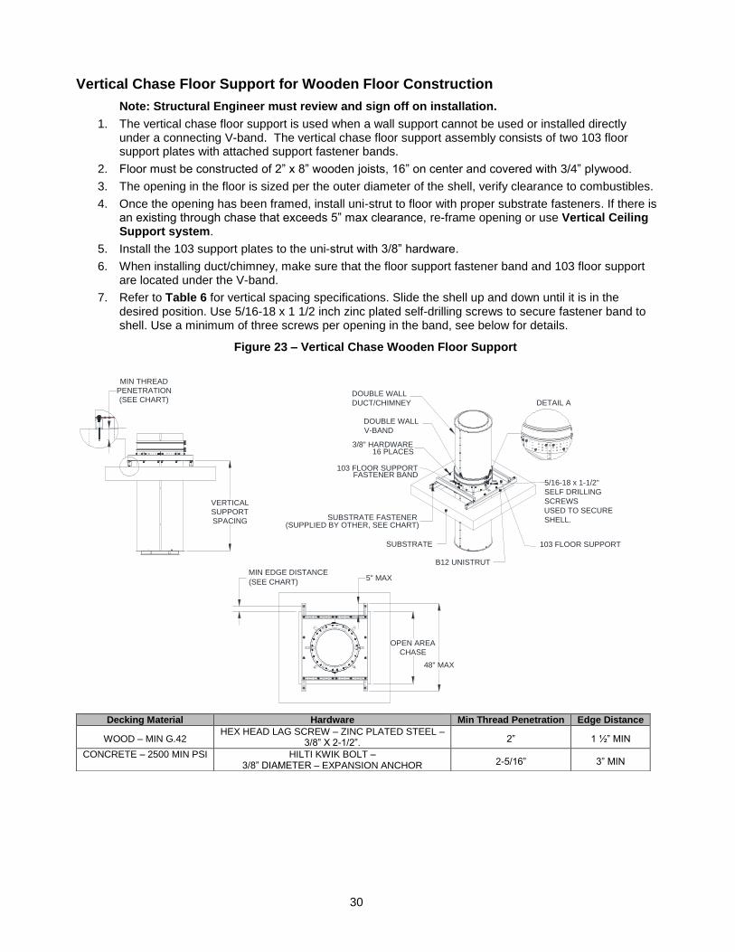
Vertical Chase Floor Support for Wooden Floor Construction
Note: Structural Engineer must review and sign off on installation.
1. The vertical chase floor support is used when a wall support cannot be used or installed directly under a connecting V-band. The vertical chase floor support assembly consists of two 103 floor support plates with attached support fastener bands.
2. Floor must be constructed of 2” x 8” wooden joists, 16” on center and covered with 3/4” plywood.
3. The opening in the floor is sized per the outer diameter of the shell, verify clearance to combustibles.
4. Once the opening has been framed, install uni-strut to floor with proper substrate fasteners. If there is an existing through chase that exceeds 5” max clearance, re-frame opening or use Vertical Ceiling Support system.
5. Install the 103 support plates to the uni-strut with 3/8” hardware.
6. When installing duct/chimney, make sure that the floor support fastener band and 103 floor support are located under the V-band.
7. Refer to Table 6 for vertical spacing specifications. Slide the shell up and down until it is in the desired position. Use 5/16-18 x 1 1/2 inch zinc plated self-drilling screws to secure fastener band to shell. Use a minimum of three screws per opening in the band, see below for details.
SUBSTRATE
B12 UNISTRUT
103 FLOOR SUPPORT
DOUBLE WALL
DUCT/CHIMNEY
DOUBLE WALL
V-BAND
103 FLOOR SUPPORTFASTENER BAND
SUBSTRATE FASTENER(SUPPLIED BY OTHER, SEE CHART)
3/8" HARDWARE16 PLACES
5" MAX
OPEN AREA
CHASE
MIN EDGE DISTANCE
(SEE CHART)
48" MAX
VERTICAL
SUPPORT
SPACING
MIN THREAD
PENETRATION
(SEE CHART)
5/16-18 x 1-1/2"
SELF DRILLING
SCREWS
USED TO SECURE
SHELL.
DETAIL A
Decking Material Hardware Min Thread Penetration Edge Distance
WOOD – MIN G.42 HEX HEAD LAG SCREW – ZINC PLATED STEEL –
3/8” X 2-1/2”. 2” 1 ½” MIN
CONCRETE – 2500 MIN PSI HILTI KWIK BOLT – 3/8” DIAMETER – EXPANSION ANCHOR 2-5/16” 3” MIN
Figure 23 – Vertical Chase Wooden Floor Support
31
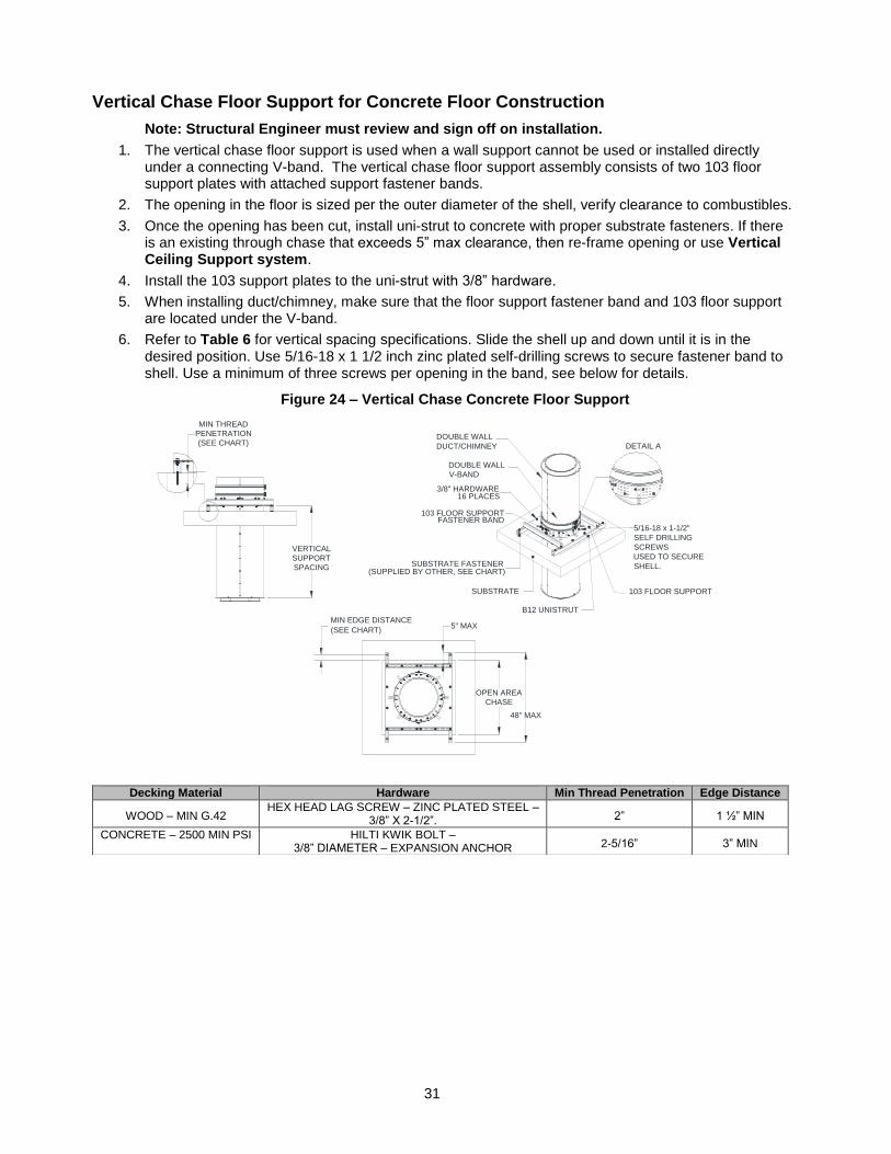
Vertical Chase Floor Support for Concrete Floor Construction
Note: Structural Engineer must review and sign off on installation.
1. The vertical chase floor support is used when a wall support cannot be used or installed directly under a connecting V-band. The vertical chase floor support assembly consists of two 103 floor support plates with attached support fastener bands.
2. The opening in the floor is sized per the outer diameter of the shell, verify clearance to combustibles.
3. Once the opening has been cut, install uni-strut to concrete with proper substrate fasteners. If there is an existing through chase that exceeds 5” max clearance, then re-frame opening or use Vertical Ceiling Support system.
4. Install the 103 support plates to the uni-strut with 3/8” hardware.
5. When installing duct/chimney, make sure that the floor support fastener band and 103 floor support are located under the V-band.
6. Refer to Table 6 for vertical spacing specifications. Slide the shell up and down until it is in the desired position. Use 5/16-18 x 1 1/2 inch zinc plated self-drilling screws to secure fastener band to shell. Use a minimum of three screws per opening in the band, see below for details.
SUBSTRATE
B12 UNISTRUT
103 FLOOR SUPPORT
DOUBLE WALL
DUCT/CHIMNEY
DOUBLE WALL
V-BAND
103 FLOOR SUPPORTFASTENER BAND
SUBSTRATE FASTENER(SUPPLIED BY OTHER, SEE CHART)
3/8" HARDWARE16 PLACES
5" MAX
OPEN AREA
CHASE
MIN EDGE DISTANCE
(SEE CHART)
48" MAX
VERTICAL
SUPPORT
SPACING
MIN THREAD
PENETRATION
(SEE CHART)
5/16-18 x 1-1/2"
SELF DRILLING
SCREWS
USED TO SECURE
SHELL.
DETAIL A
Decking Material Hardware Min Thread Penetration Edge Distance
WOOD – MIN G.42 HEX HEAD LAG SCREW – ZINC PLATED STEEL –
3/8” X 2-1/2”. 2” 1 ½” MIN
CONCRETE – 2500 MIN PSI HILTI KWIK BOLT – 3/8” DIAMETER – EXPANSION ANCHOR 2-5/16” 3” MIN
Figure 24 – Vertical Chase Concrete Floor Support
32
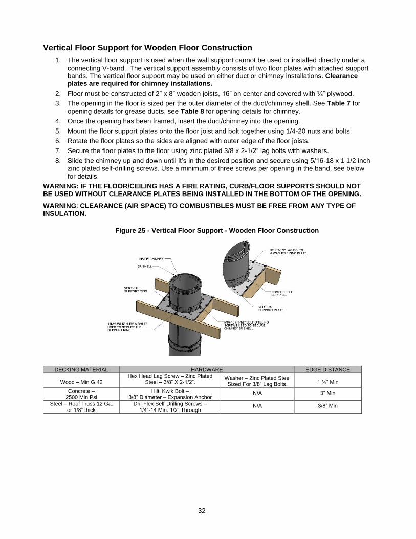
Vertical Floor Support for Wooden Floor Construction
1. The vertical floor support is used when the wall support cannot be used or installed directly under a connecting V-band. The vertical support assembly consists of two floor plates with attached support bands. The vertical floor support may be used on either duct or chimney installations. Clearance plates are required for chimney installations.
2. Floor must be constructed of 2” x 8” wooden joists, 16” on center and covered with ¾” plywood.
3. The opening in the floor is sized per the outer diameter of the duct/chimney shell. See Table 7 for opening details for grease ducts, see Table 8 for opening details for chimney.
4. Once the opening has been framed, insert the duct/chimney into the opening.
5. Mount the floor support plates onto the floor joist and bolt together using 1/4-20 nuts and bolts.
6. Rotate the floor plates so the sides are aligned with outer edge of the floor joists.
7. Secure the floor plates to the floor using zinc plated 3/8 x 2-1/2” lag bolts with washers.
8. Slide the chimney up and down until it’s in the desired position and secure using 5/16-18 x 1 1/2 inch zinc plated self-drilling screws. Use a minimum of three screws per opening in the band, see below for details.
WARNING: IF THE FLOOR/CEILING HAS A FIRE RATING, CURB/FLOOR SUPPORTS SHOULD NOT BE USED WITHOUT CLEARANCE PLATES BEING INSTALLED IN THE BOTTOM OF THE OPENING.
WARNING: CLEARANCE (AIR SPACE) TO COMBUSTIBLES MUST BE FREE FROM ANY TYPE OF INSULATION.
DECKING MATERIAL HARDWARE EDGE DISTANCE
Wood – Min G.42
Hex Head Lag Screw – Zinc Plated Steel – 3/8” X 2-1/2”.
Washer – Zinc Plated Steel Sized For 3/8” Lag Bolts.
1 ½” Min
Concrete – 2500 Min Psi
Hilti Kwik Bolt – 3/8” Diameter – Expansion Anchor
N/A 3” Min
Steel – Roof Truss 12 Ga. or 1/8” thick
Dril-Flex Self-Drilling Screws – 1/4”-14 Min. 1/2” Through
N/A 3/8” Min
Figure 25 - Vertical Floor Support - Wooden Floor Construction
33
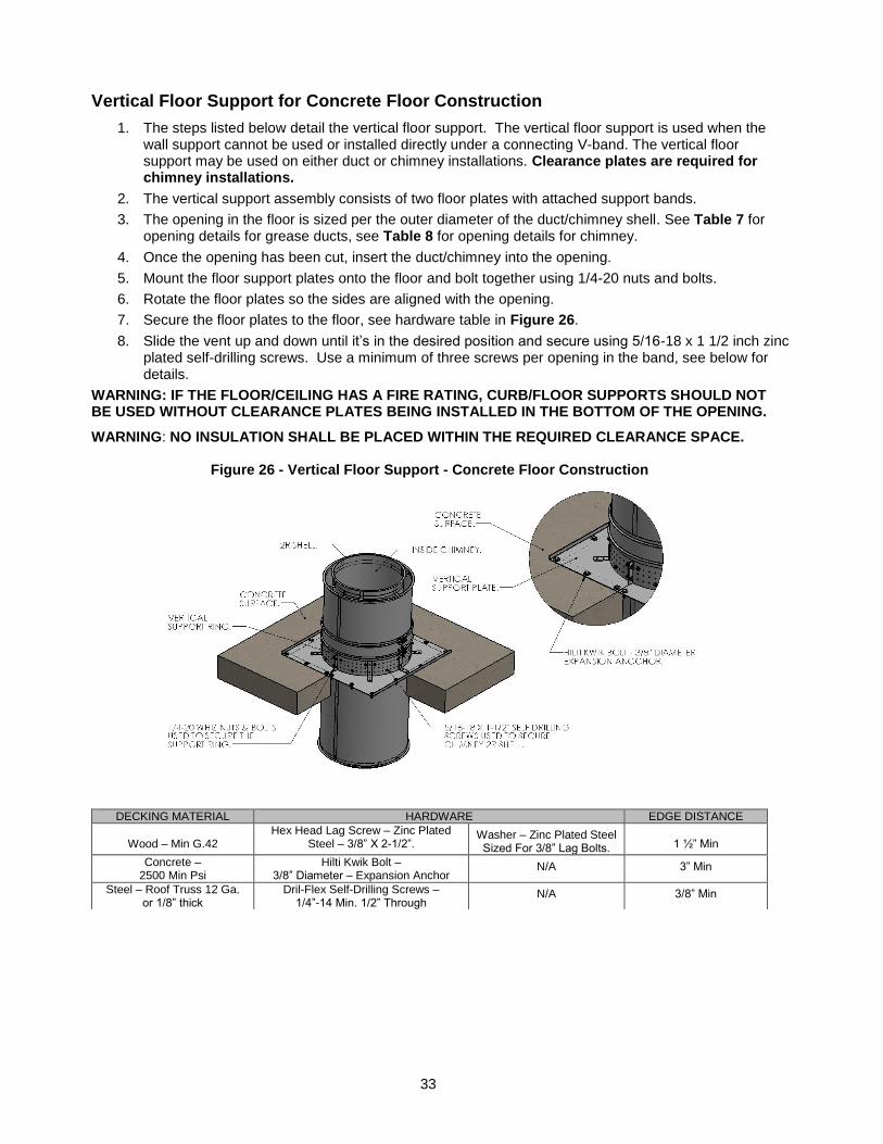
Vertical Floor Support for Concrete Floor Construction
1. The steps listed below detail the vertical floor support. The vertical floor support is used when the wall support cannot be used or installed directly under a connecting V-band. The vertical floor support may be used on either duct or chimney installations. Clearance plates are required for chimney installations.
2. The vertical support assembly consists of two floor plates with attached support bands.
3. The opening in the floor is sized per the outer diameter of the duct/chimney shell. See Table 7 for opening details for grease ducts, see Table 8 for opening details for chimney.
4. Once the opening has been cut, insert the duct/chimney into the opening.
5. Mount the floor support plates onto the floor and bolt together using 1/4-20 nuts and bolts.
6. Rotate the floor plates so the sides are aligned with the opening.
7. Secure the floor plates to the floor, see hardware table in Figure 26.
8. Slide the vent up and down until it’s in the desired position and secure using 5/16-18 x 1 1/2 inch zinc plated self-drilling screws. Use a minimum of three screws per opening in the band, see below for details.
WARNING: IF THE FLOOR/CEILING HAS A FIRE RATING, CURB/FLOOR SUPPORTS SHOULD NOT BE USED WITHOUT CLEARANCE PLATES BEING INSTALLED IN THE BOTTOM OF THE OPENING.
WARNING: NO INSULATION SHALL BE PLACED WITHIN THE REQUIRED CLEARANCE SPACE.
DECKING MATERIAL HARDWARE EDGE DISTANCE
Wood – Min G.42
Hex Head Lag Screw – Zinc Plated Steel – 3/8” X 2-1/2”.
Washer – Zinc Plated Steel Sized For 3/8” Lag Bolts.
1 ½” Min
Concrete – 2500 Min Psi
Hilti Kwik Bolt – 3/8” Diameter – Expansion Anchor
N/A 3” Min
Steel – Roof Truss 12 Ga. or 1/8” thick
Dril-Flex Self-Drilling Screws – 1/4”-14 Min. 1/2” Through
N/A 3/8” Min
Figure 26 - Vertical Floor Support - Concrete Floor Construction
34
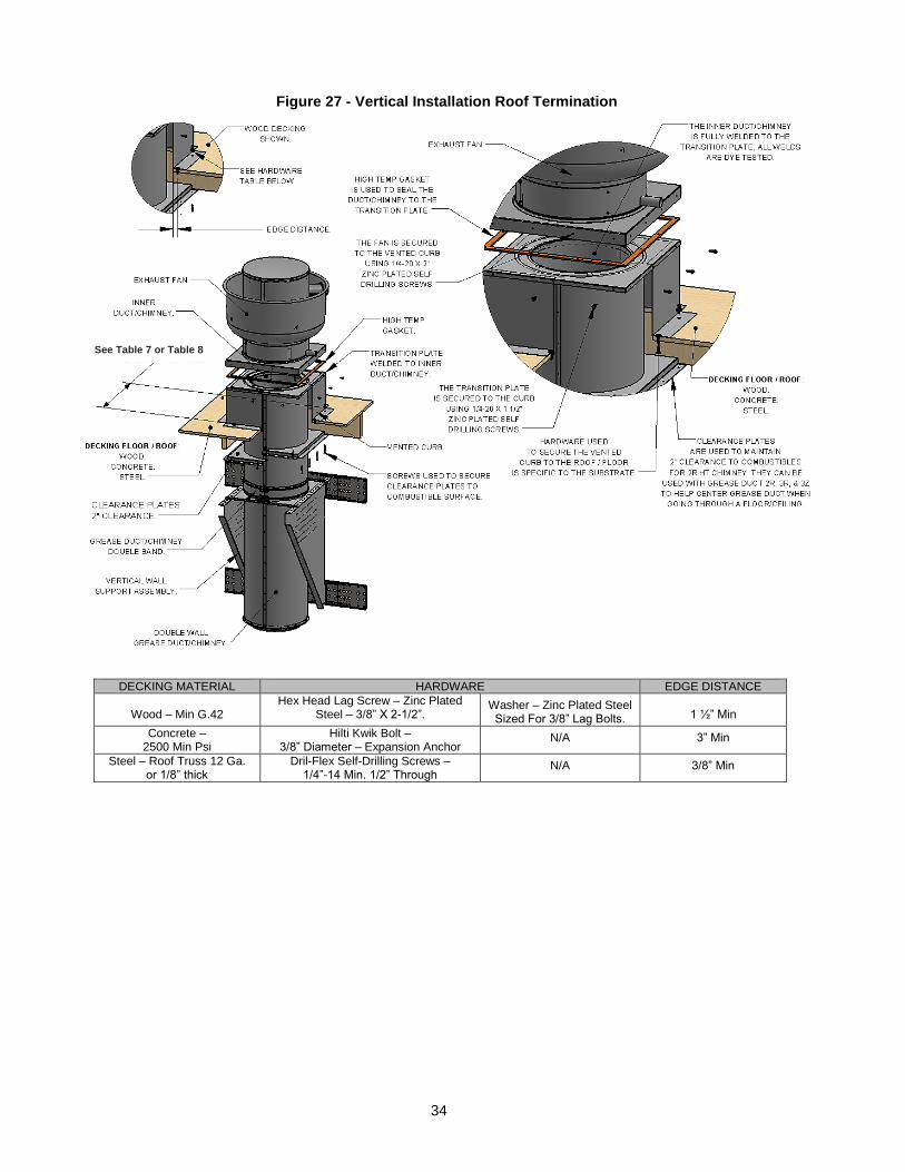
DECKING MATERIAL HARDWARE EDGE DISTANCE
Wood – Min G.42
Hex Head Lag Screw – Zinc Plated Steel – 3/8” X 2-1/2”.
Washer – Zinc Plated Steel Sized For 3/8” Lag Bolts.
1 ½” Min
Concrete – 2500 Min Psi
Hilti Kwik Bolt – 3/8” Diameter – Expansion Anchor
N/A 3” Min
Steel – Roof Truss 12 Ga. or 1/8” thick
Dril-Flex Self-Drilling Screws – 1/4”-14 Min. 1/2” Through
N/A 3/8” Min
Figure 27 - Vertical Installation Roof Termination
See Table 7 or Table 8
35
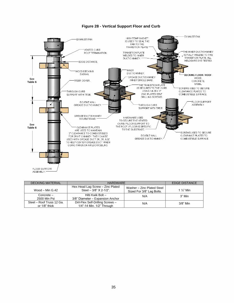
DECKING MATERIAL HARDWARE EDGE DISTANCE
Wood – Min G.42
Hex Head Lag Screw – Zinc Plated Steel – 3/8” X 2-1/2”.
Washer – Zinc Plated Steel Sized For 3/8” Lag Bolts.
1 ½” Min
Concrete – 2500 Min Psi
Hilti Kwik Bolt – 3/8” Diameter – Expansion Anchor
N/A 3” Min
Steel – Roof Truss 12 Ga. or 1/8” thick
Dril-Flex Self-Drilling Screws – 1/4”-14 Min. 1/2” Through
N/A 3/8” Min
Figure 28 - Vertical Support Floor and Curb
See Table 6
See Table 6
36
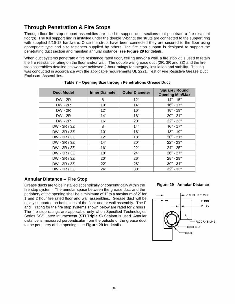
Through Penetration & Fire Stops Through floor fire stop support assemblies are used to support duct sections that penetrate a fire resistant floor(s). The full support ring is installed under the double V-band; the struts are connected to the support ring with supplied 5/16-18 hardware. Once the struts have been connected they are secured to the floor using appropriate type and size fasteners supplied by others. The fire stop support is designed to support the penetrating duct section and maintain annular distance, see Figure 29 for details.
When duct systems penetrate a fire resistance rated floor, ceiling and/or a wall, a fire stop kit is used to retain the fire resistance rating on the floor and/or wall. The double wall grease duct (2R, 3R and 3Z) and the fire stop assemblies detailed below have achieved 2-hour ratings for integrity, insulation and stability. Testing was conducted in accordance with the applicable requirements UL 2221, Test of Fire Resistive Grease Duct Enclosure Assemblies.
Table 7 – Opening Size through Penetrations Grease Duct
Annular Distance – Fire Stop
Grease ducts are to be installed eccentrically or concentrically within the fire stop system. The annular space between the grease duct and the periphery of the opening shall be a minimum of 1” to a maximum of 2” for 1 and 2 hour fire rated floor and wall assemblies. Grease duct will be rigidly supported on both sides of the floor and or wall assembly. The F and T rating for the fire stop systems shown below are rated for 2 hours. The fire stop ratings are applicable only when Specified Technologies Series SSS Latex Intumescent (STI Triple S) Sealant is used. Annular distance is measured perpendicular from the outside of the grease duct to the periphery of the opening, see Figure 29 for details.
Duct Model Inner Diameter Outer Diameter Square / Round
Opening Min/Max
DW - 2R 8" 12" 14” - 15"
DW - 2R 10" 14" 16” - 17"
DW - 2R 12" 16" 18” - 19"
DW - 2R 14" 18" 20” - 21"
DW - 2R 16" 20" 22” - 23"
DW - 3R / 3Z 8" 14" 16” - 17"
DW - 3R / 3Z 10" 16" 18” - 19"
DW - 3R / 3Z 12" 18" 20” - 21"
DW - 3R / 3Z 14" 20" 22” - 23"
DW - 3R / 3Z 16" 22" 24” - 25"
DW - 3R / 3Z 18" 24" 26” - 27"
DW - 3R / 3Z 20" 26" 28” - 29"
DW - 3R / 3Z 22” 28” 30” - 31”
DW - 3R / 3Z 24" 30" 32” - 33"
Figure 29 - Annular Distance
37
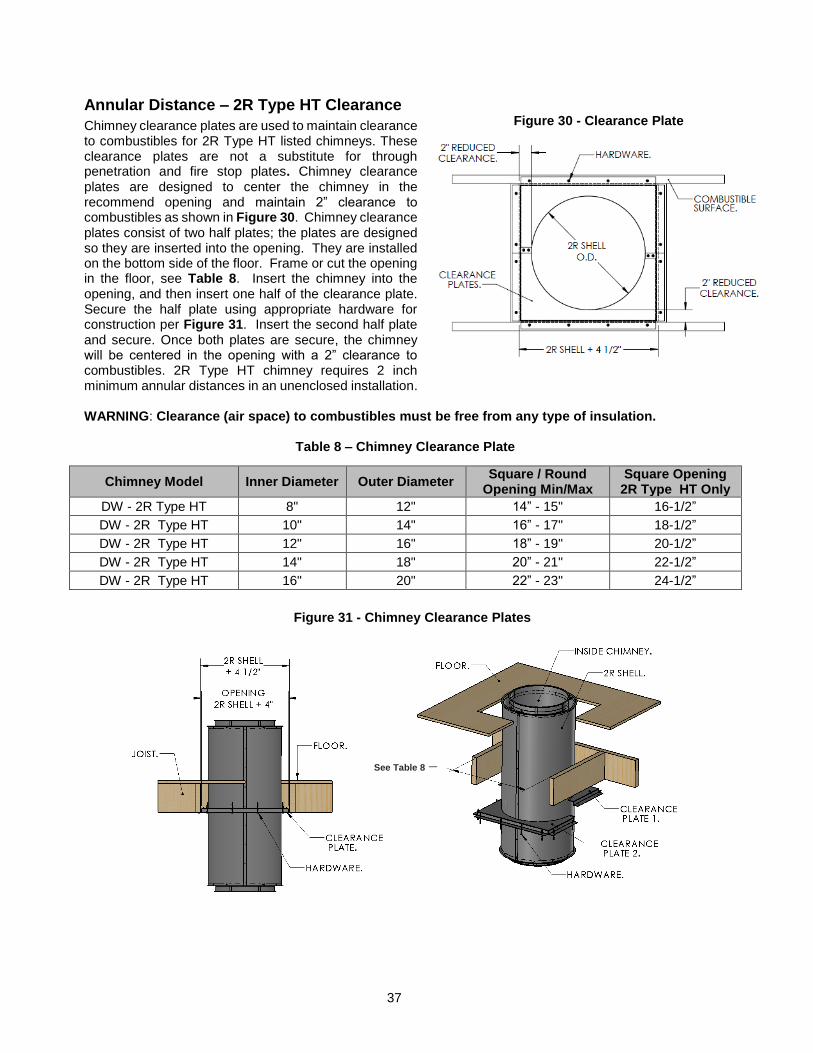
Annular Distance – 2R Type HT Clearance
Chimney clearance plates are used to maintain clearance to combustibles for 2R Type HT listed chimneys. These clearance plates are not a substitute for through penetration and fire stop plates. Chimney clearance plates are designed to center the chimney in the recommend opening and maintain 2” clearance to combustibles as shown in Figure 30. Chimney clearance plates consist of two half plates; the plates are designed so they are inserted into the opening. They are installed on the bottom side of the floor. Frame or cut the opening in the floor, see Table 8. Insert the chimney into the opening, and then insert one half of the clearance plate. Secure the half plate using appropriate hardware for construction per Figure 31. Insert the second half plate and secure. Once both plates are secure, the chimney will be centered in the opening with a 2” clearance to combustibles. 2R Type HT chimney requires 2 inch minimum annular distances in an unenclosed installation. WARNING: Clearance (air space) to combustibles must be free from any type of insulation.
Table 8 – Chimney Clearance Plate
Chimney Model Inner Diameter Outer Diameter Square / Round
Opening Min/Max Square Opening
2R Type HT Only
DW - 2R Type HT 8" 12" 14” - 15" 16-1/2”
DW - 2R Type HT 10" 14" 16” - 17" 18-1/2”
DW - 2R Type HT 12" 16" 18” - 19" 20-1/2”
DW - 2R Type HT 14" 18" 20” - 21" 22-1/2”
DW - 2R Type HT 16" 20" 22” - 23" 24-1/2”
Figure 30 - Clearance Plate
See Table 8 –
Chimney
Clearance
PlateTable
7
Figure 31 - Chimney Clearance Plates
38
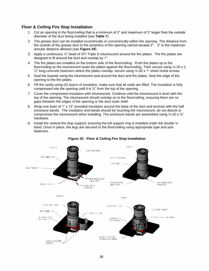
Floor & Ceiling Fire Stop Installation
1. Cut an opening in the floor/ceiling that is a minimum of 2” and maximum of 3” larger than the outside diameter of the duct being installed (see Table 7).
2. The grease duct can be installed eccentrically or concentrically within the opening. The distance from the outside of the grease duct to the periphery of the opening cannot exceed 2”. 2” is the maximum annular distance allowed (see Figure 29).
3. Apply a continuous ½” bead of STI Triple S intumescent around the fire plates. The fire plates are designed to fit around the duct and overlap by 1”.
4. The fire plates are installed on the bottom side of the floor/ceiling. Push the plates up to the floor/ceiling so the intumescent seals the plates against the floor/ceiling. Then secure using ¼-20 x 1 ½” long concrete fasteners where the plates overlap, secure using ¼-20 x 1” sheet metal screws.
5. Seal the topside using the intumescent seal around the duct and fire plates. Seal the edge of the opening to the fire plates.
6. Fill the cavity using (4) layers of insulation, make sure that all voids are filled. The insulation is fully compressed into the opening until it is ¾” from the top of the opening.
7. Cover the compressed insulation with intumescent. Continue until the intumescent is level with the top of the opening. The intumescent should overlap on to the floor/ceiling, ensuring there are no gaps between the edges of the opening or the duct outer shell.
8. Wrap one layer of 1” x 12” provided insulation around the base of the duct and enclose with the half enclosure bands. The insulation and bands should be touching the intumescent, do not disturb or compromise the intumescent when installing. The enclosure bands are assembled using ¼-20 x ¾” hardware.
9. Install the vertical fire stop support; ensuring the full support ring is installed under the double V-band. Once in place, the legs are secured to the floor/ceiling using appropriate type and size fasteners.
Figure 32 - Floor & Ceiling Fire Stop Installation
See Table 7
39
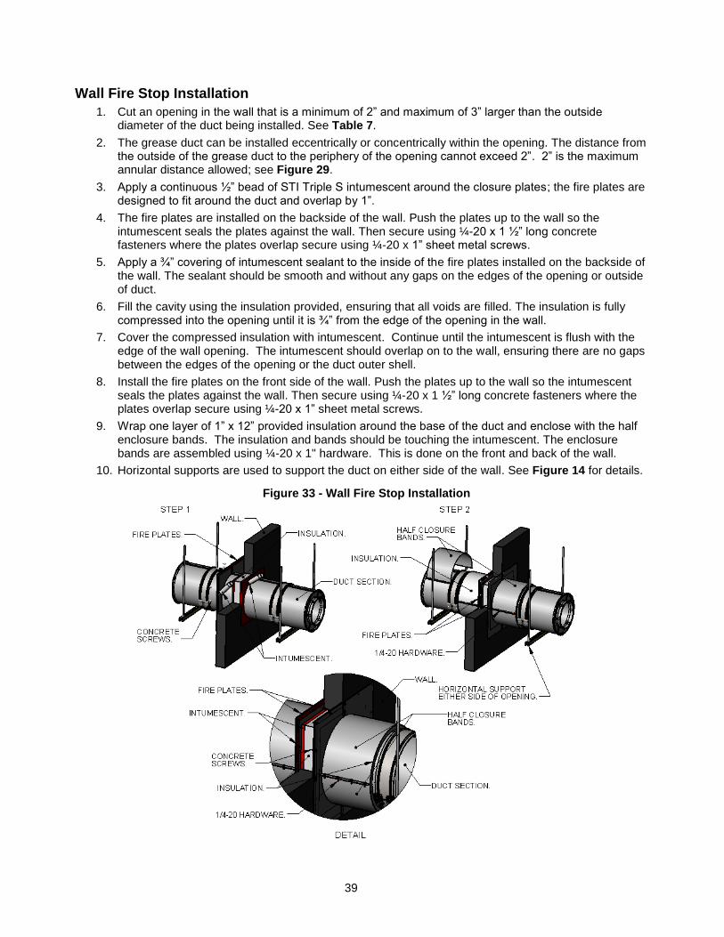
Wall Fire Stop Installation
1. Cut an opening in the wall that is a minimum of 2” and maximum of 3” larger than the outside diameter of the duct being installed. See Table 7.
2. The grease duct can be installed eccentrically or concentrically within the opening. The distance from the outside of the grease duct to the periphery of the opening cannot exceed 2”. 2” is the maximum annular distance allowed; see Figure 29.
3. Apply a continuous ½” bead of STI Triple S intumescent around the closure plates; the fire plates are designed to fit around the duct and overlap by 1”.
4. The fire plates are installed on the backside of the wall. Push the plates up to the wall so the intumescent seals the plates against the wall. Then secure using ¼-20 x 1 ½” long concrete fasteners where the plates overlap secure using ¼-20 x 1” sheet metal screws.
5. Apply a ¾” covering of intumescent sealant to the inside of the fire plates installed on the backside of the wall. The sealant should be smooth and without any gaps on the edges of the opening or outside of duct.
6. Fill the cavity using the insulation provided, ensuring that all voids are filled. The insulation is fully compressed into the opening until it is ¾” from the edge of the opening in the wall.
7. Cover the compressed insulation with intumescent. Continue until the intumescent is flush with the edge of the wall opening. The intumescent should overlap on to the wall, ensuring there are no gaps between the edges of the opening or the duct outer shell.
8. Install the fire plates on the front side of the wall. Push the plates up to the wall so the intumescent seals the plates against the wall. Then secure using ¼-20 x 1 ½” long concrete fasteners where the plates overlap secure using ¼-20 x 1” sheet metal screws.
9. Wrap one layer of 1” x 12” provided insulation around the base of the duct and enclose with the half enclosure bands. The insulation and bands should be touching the intumescent. The enclosure bands are assembled using ¼-20 x 1" hardware. This is done on the front and back of the wall.
10. Horizontal supports are used to support the duct on either side of the wall. See Figure 14 for details.
Figure 33 - Wall Fire Stop Installation
40
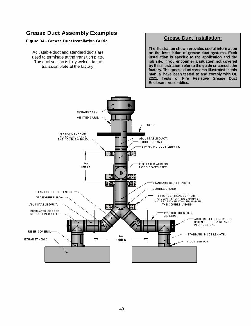
Grease Duct Assembly Examples
Figure 34 - Grease Duct Installation Guide
Grease Duct Installation:
The illustration shown provides useful information on the installation of grease duct systems. Each installation is specific to the application and the job site. If you encounter a situation not covered by this illustration, refer to the guide or consult the factory. The grease duct systems illustrated in this manual have been tested to and comply with UL 2221, Tests of Fire Resistive Grease Duct Enclosure Assemblies.
Adjustable duct and standard ducts are used to terminate at the transition plate. The duct section is fully welded to the
transition plate at the factory.
See
Table 5
See Table 6
41
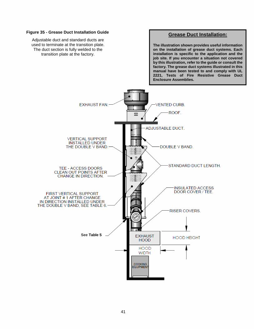
Figure 35 - Grease Duct Installation Guide
Adjustable duct and standard ducts are used to terminate at the transition plate. The duct section is fully welded to the
transition plate at the factory.
Grease Duct Installation:
The illustration shown provides useful information on the installation of grease duct systems. Each installation is specific to the application and the job site. If you encounter a situation not covered by this illustration, refer to the guide or consult the factory. The grease duct systems illustrated in this manual have been tested to and comply with UL 2221, Tests of Fire Resistive Grease Duct Enclosure Assemblies.
See Table 5
42
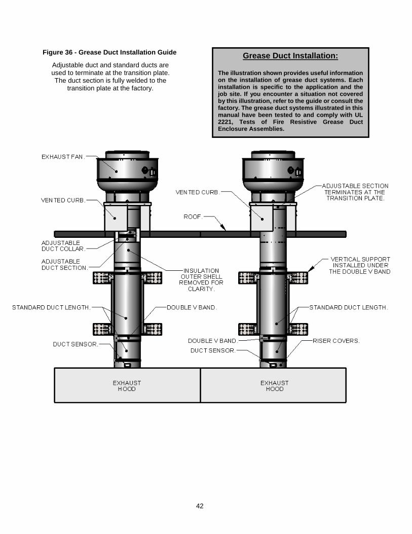
Figure 36 - Grease Duct Installation Guide
Adjustable duct and standard ducts are used to terminate at the transition plate. The duct section is fully welded to the
transition plate at the factory.
Grease Duct Installation:
The illustration shown provides useful information on the installation of grease duct systems. Each installation is specific to the application and the job site. If you encounter a situation not covered by this illustration, refer to the guide or consult the factory. The grease duct systems illustrated in this manual have been tested to and comply with UL 2221, Tests of Fire Resistive Grease Duct Enclosure Assemblies.
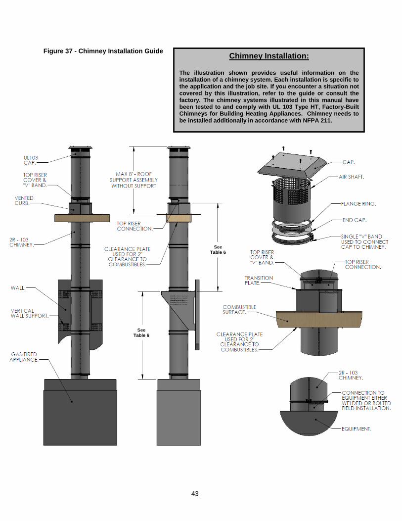
43
Figure 37 - Chimney Installation Guide
Chimney Installation:
The illustration shown provides useful information on the installation of a chimney system. Each installation is specific to the application and the job site. If you encounter a situation not covered by this illustration, refer to the guide or consult the factory. The chimney systems illustrated in this manual have been tested to and comply with UL 103 Type HT, Factory-Built Chimneys for Building Heating Appliances. Chimney needs to be installed additionally in accordance with NFPA 211.
See Table 6
See Table 6
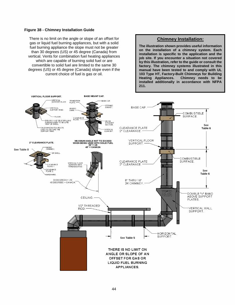
44
Figure 38 - Chimney Installation Guide
Chimney Installation:
The illustration shown provides useful information on the installation of a chimney system. Each installation is specific to the application and the job site. If you encounter a situation not covered by this illustration, refer to the guide or consult the factory. The chimney systems illustrated in this manual have been tested to and comply with UL 103 Type HT, Factory-Built Chimneys for Building Heating Appliances. Chimney needs to be installed additionally in accordance with NFPA 211.
There is no limit on the angle or slope of an offset for gas or liquid fuel burning appliances, but with a solid fuel burning appliance the slope must not be greater than 30 degrees (US) or 45 degree (Canada) from
vertical. Vents for combination fuel heating appliances which are capable of burning solid fuel or are
convertible to solid fuel are limited to the same 30 degrees (US) or 45 degree (Canada) slope even if the
current choice of fuel is gas or oil.
See Table 8 –
Chimne
y
Clearan
ce Plate
See Table 5
See Table 6
See Table 6
45
METHODS USED TO TEST DUCT AFTER ASSEMBLY Prior to the concealment of any portion of a grease duct system, a leakage test shall be performed in the presence of the code official.
Duct shall be considered to be concealed when installed in shafts, or covered by coatings or wraps that prevent the ductwork from being visually inspected on all sides. A light test or approved equivalent test method (smoke or pressure test) shall be performed to determine that all joints are liquid tight. The smoke or pressure test is used for longer duct runs while the light test is used for short duct runs, all methods are approved for use.
The above mentioned leakage tests are not specific to the listing(s) requirements of the system being tested. The code official may have specific requirements other than above and should be consulted before final inspection.
Method 1 – Light Test per IMC 506.3.2.5 A light test shall be performed by passing a lamp having a power rating of not less than 100 watts through the entire section of ductwork to be tested. The lamp shall be open so as to emit light equally in all directions perpendicular to the duct walls. The test shall be performed for the entire duct system, including the hood-to-duct connection. The ductwork shall be permitted to be tested in sections, provided that every joint is tested. For listed factory-built grease ducts, this test shall be limited to duct joints assembled in the field and shall exclude factory welds.
Method 2 – Smoke Test After the ductwork has been installed allow the listed sealant to cure for a minimum of 24 hours. Smoke bombs are lit and placed at the bottom of the duct system; natural upwards drafts will pull the smoke to the top of the duct system. Various length duct runs may require multiple smoke bombs. Once the smoke has reached the top of the duct run, cap the duct securely. Inspect all joints for leakage.
Method 3 – Pressure Testing per SMACNA’s HVAC Air Duct Leakage Testing and balancing shall be performed prior to the pressure duct leakage test.
A duct pressure test shall be performed during initial installation by the permit holder or its testing agency using the appropriate local code testing procedure. This test must be performed as a rough inspection prior to being covered, concealed, insulated or wrapped before final installation to the exhaust fan, kitchen exhaust hood, or other equipment. In the absence of any local code testing procedures, use SMACNA’s HVAC Air Duct Leakage Test Manual for inspection and testing guidelines.
If the duct system is modified or renovated, the entire system will require re-testing.
46
GENERAL DUCT WEIGHTS The average weight of the duct, per foot of length, can be calculated using the following formulas below. Duct design should provide adequate support to ensure duct components are not overloaded.
Weight – DW-2R The following formula can be used to approximate the weight of total length of DW-2R double wall duct. Inner Shell + Outer Shell + Insulation or (.0327*L*D) + [.0218*L*(D+4)] + [.0364*L*(D+2)].
Weight – DW-3R
The following formula can be used to approximate the weight of total lengths of DW-3R double wall duct. Inner Shell + Outer Shell + Insulation or (.0327*L*D) + [.0218*L*(D+6)] + [.0436*L*(D+3)].
Weight – DW-3Z The following formula can be used to approximate the weight of total lengths of DW-3Z double wall duct. Inner Shell + Outer Shell + Insulation or (.0327*L*D) + [.0218*L*(D+6)] + [.0491*L*(D+3)].
Weight – Example The “D” value in the formulas above represents the inner duct diameter in inches. The “L” value in the formulas above represents the total length in inches. Duct system: DW-3Z, 12” inner duct, 100 FT long. Using the DW-3Z formula above, (.0327*1200*12) + (.0218*1200*18) + (.0491*1200*15) = 1825 lbs.

47
48
CLEANING & MAINTENANCE RECORD
Date Service Performed
Factory Service Center
Phone: 1-866-784-6900 Fax: 1-919-554-9374