nondestructive tests determine - gpo · nondestructiveteststodetermine...
TRANSCRIPT

NBSIR 75-729
Nondestructive Tests to Determine
Concrete Strength -
A Status Report
James R, Clifton
Materials and Composites Section
Structures, Materials and Safety Division
Center for Building Technology, IAT
July 1975
Final
Prepared for
Building Safety Section
Structures, Materials and Safety Division
Center for Building Technology, IAT
National Bureau of Standards
Washington, D. C. 20234


NBSIR 75-729
NONDESTRUCTIVE TESTS TO DETERMINE
CONCRETE STRENGTH -
A STATUS REPORT
James R. Clifton
Materials and Composites Section
Structures, Materials and Safety Division
Center for Building Technology, I AT
July 1975
Prepared for
Building Safety Section
Structures, Materials and Safety Division
Center for Building Technology, IAT
National Bureau of Standards
Washington, D. C. 20234
U.S. DEPARTMENT OF COMMERCE, Rogers C.B. Morton, Secretary
John K. Tabor, Under Secretary
Dr. Betsy Ancker-Johnson, Assistant Secretary for Science and Technology
Final
NATIONAL BUREAU OF STANDARDS, Ernest Ambler, Acting Director


TABLE OF CONTENTS
Page
ABSTRACT 1
1. INTRODUCTION 1
2. NONDESTRUCTIVE TEST METHODS 1
2.1 Probing Methods 2
2.1.1 Description of the Windsor Probe 2
2.1.2 Windsor Probe for Cornpressive Strength Determinations 2
2.1.3 Advantages and Limitations 3
2.1.4 Research Required 3
2.1.5 Concluding Remarks 3
2.2 Rebound Method 3
2.2.1 Description of Hammer Method of Testing 4
2.2.2 Schmidt Rebound Hammer for the Determination of CompressiveStrength 4
2.2.3 Flexural Strength and Modulus of Elasticity 4
2.2.4 Advantages and Limitations of the Schmidt Rebound Hammer 5
2.2.5 Research Required 5
2.2.6 Concluding Remarks 5
2.3 Pull-Out 5
2.3.1 Test Method and Field Use 6
2.3.2 Review of Recent Studies 6
2.3.3 Advantages and Limitations 7
2.3.4 Research Required 7
2.3.5 Concluding Remarks 7
2.4 Push-Out Cylinders . . 7
2.4.1 Review of Push-Out Cylinder Studies ^. 7
2.4.2 Advantages and Limitations 8
2.4.3 Research Required and Concluding Remarks 8
2.5 Ultrasonic Pulse Velocity Method 8
2.5.1 Principle of the Ultrasonic Pulse Velocity Method 8
2.5.2 Estimation of Strength of Concrete 92.5.3 Determination of Formwork Removal Times 9
2.5.4 Advantages and Limitations 9
2.5.5 Research Required 10
2.5.6 Concluding Remarks 10
2.6 Predictions of Strength Development by Maturity and Equivalent Age 10
2.6.1 Prediction of Formwork Removal Times 112.6.2 Advantages and Limitations 11
2.6.3 Research Required 112.6.4 Concluding Remarks 13
3. COMBINATION OF NONDESTRUCTIVE TESTS 13
3.1 Combination of Ultrasonic Pulse Velocity and Rebound Hammer Methods.... 13
3.2 Concluding Remarks 14
4. PROPOSED RESEARCH AND RECOMMENDATIONS 14
5. SUMMARY AND CONCLUSIONS 15
6 . REFERENCES 17
7. FIGURE CAPTIONS 22
iii


NONDESTRUCTIVE TESTS TO DETERMINE CONCRETESTRENGTH - A STATUS REPORT
byJames R. Clifton
ABSTRACT
Individual and combined nondestructive test methods have beencritically reviewed as potential methods to determine safe formworkremoval times. The techniques reviewed are the Windsor probe, theSchmidt Rebound Hammer, pull-out measurements, push-out cylinders,ultrasonic pulse velocity measurements, and the maturity and equivalentage concepts. The individual methods, themselves, do not give goodestimates of the in situ strengths of concretes and it is recommendedthat future research emphasize combined methods.
A proposed research program which emphasizes combined nondestructivetest methods has been developed.
Key Words: Compressive strength; concrete; flexural strength;formwork removal; nondestructive testing; surface hardness.
1. INTRODUCTION
This report is based on a critical literature review of nondestructive test methodsfor estimating the early-age strength of in situ concrete. The estimation of the strengthof concretes at early ages is important in deciding when the formwork can be safely removed.
The premature removal of forms has resulted not only in numerous collapses [1, 2] , butalso in the often unreported sagging of partially cured concrete and in the development ofhairline cracks which subsequently lead to serious maintenance problems [1]
.
Nondestructive testing of mature concrete has been the subject of symposia [3-6]
,
review articles [7-10] and several books [11-13] . However, the current review disclosesthat relatively little attention has been given to nondestructive methods for estimatingthe early-age strengths of concretes.
Many of the test methods classified as being nondestructive do cause sufficientdamage to the concrete that minor repairs are necessary. These methods are nondestructivein that the specimen being tested is not severely damaged or destroyed.
The nondestructive test methods covered in this report are those applicable to theestimation, of either the in situ strength of concrete or the quality of concrete. There-fore, radioactive, x-ray, and electrical nondestructive test methods are not included.This report is also restricted, with the exception of the push-out test method (Section2.4) , to tests which can be performed on site (if the proper calibration tables or chartshave been previously prepared) . Both individual and combined nondestructive test methodsare discussed.
2. NONDESTRUCTIVE TEST METHODS
The individual nondestructive test methods of this section are evaluated on the basisof their apparent reliability, accuracy, ease of use, and information obtained. Theirapplicability to the determination of formwork removal times is considered as well astheir advantages and limitations. Recommendations on needed research are also given.
1

2.1 Probing Methods
The probing methods used to measure the surface hardness of concrete are based ondepth of penetration of probes in the concrete. The probe results are converted intocompressive strengths by a correlation graph which is a construction of depth of penetrationversus experimentally measured compressive strengths. Based on this correlation chart thein situ compressive strength of concrete can be estimated.
The first hardness measurements of concrete by probing techniques were reported byVoellmy [14], in 1954. He used two techniques: (1) a special hammer device was used toperforate concrete and afterwards the depth of the bore hole was measured; and (2) thedepth of penetration of pins which were blasted into the concrete was measured. Neithertechnique gained wide acceptance. In the middle 1960 's the Windsor Probe was developedby the Port of New York Authority, New York, and the Windsor Machinery Company, Connecticut.Cantor presented [15] the results of the investigations performed by the Port of New YorkAuthority. The Windsor Probe technique is becoming an acceptable nondestructive testtechnique, as evidenced by the amount of recent investigations performed [16-21] to assessits reliability. The Nondestructive Testing Subcommittee of ASTM Committee C-9 is currentlydrafting specifications giving guidelines for the usage of the probe method.
2.1.1 Description of the Windsor Probe
The Windsor Probe device consists of a special driving gun into which is inserted ahigh-strength metal probe that is driven into the concrete by the firing of a powdercharge (figure 1) . Different probe shapes are available, as shown in figure 2. Thelength of the probe extending from the surface of the concrete can be measured using adevice supplied by the manufacturer (figure 3)
.
The manufacturer supplies a set of 5 calibration curves, each curve corresponding toa specific Mohns' hardness for the coarse aggregate used in the concrete, by which probemeasurements can be converted to strength measurements. However, several investigationshave observed [17, 19-22] that use of the manufacturer's calibration curves often resultsin grossly incorrect estimates of the compressive strength of concretes. These investiga-tions recommend that the Windsor Probe should be calibrated by the individual user, andshould be recalibrated whenever the type of aggregate is changed.
Methods for calibrating the Windsor Probe are given by Malhotra [9] and by Keeton andHernandez [23]
.
2.1.2 Windsor Probe for Compressive Strength Determinations
The relationship between the depth of penetration of the probe and the compressivestrength appears to be only empirical as the penetration of the probe produces a complexmixture of tensile, shear, frictional, and compressive forces [19] . The estimation ofcompressive strengths with the Windsor Probe, therefore, must be made using a correlationdiagram, with appropriate confidence limits.
The published results [17-21] reviewed by the author, indicate that the variations inthe probe test
2results are large. Cantor [15] measured a standard deviation of about 1550
psi (10.7 MN/m ) , a coefficient of variation of about 35 percent and a range in predictedcompressive strength of 5600 psi (38.6 MN/m ) , in a program based on 625 probe tests of asingle concrete. These values are about ten-fold higher than those obtained by him withcompression measurements of standard cylinders and drilled cores.
Ami [19-20] constructed a plot of probe measurements versus compressive strength(measured using 6" x 12" (.15 x .30 m) standard cylinders) and calculated the regressionline and 95 percent confidence limits (based on 99 probes fired into the_top of slabs madewith 1 inch (.025 m) aggregate) . This plot is shown in figure 4, where P is the averageprobe value, ^is the average compressive strength and the subscripts 1 and u representthe lower and upper 95 percent confidence limits. The final 95 percent confidence limitband for the strength resulting from the combined compressive strength and probe confidencelevels, is fr^m S,, 3290 psi (22.6 Mn/m ) to S , 5650 psi (39.9 MN/m ) , or a range of 2360psi (6.2 MN/m ) . Ami also statistically analyzed the data based on being able to detect
2

a difference of 200 psi (.138 MN/m ) from the true strength with a Type I (a) error of
0.10 and a Type II (g) error of 0.10. (This means that the average of a group of tests
would exhibit a significant difference from an assumed true strength one time in 10 whenthe actual strength difference is 200 psi2(1.38 MN/m ) or less and 9 times in 10 when the
difference is actually 200 psi (1.38 MN/m ) or greater) . He determined that abou£ 85
probes would be required to detect the average strength within 200 psi (1.38 MN/m )
.
Large variabilities in probe test results were also observed by Malhotra [21] and byGaynor [18] . Gaynor [18] suggested that the penetration of a probe into concrete is
affected by both the strength of the concrete and other properties which have relativelylittle effect on concrete strength, such as aggregate strength, elasticity, and porosity.
He concluded that the basic heterogeneity of concrete (with hardened cement paste, mortarmatrix, and coarse aggregate phases) appears to limit the accuracy of the probe system.
Ami [19-20] and Malhotra [9] have reported that for the same concrete mix, depth of
penetration of the probes decreased with increasing age of the concrete, reflecting anincreased hardness of the concrete. However, these studies were too brief to give anydefinitive results.
2.1.3 Advantages and Limitations
The Windsor Probe equipment is simple, durable, requires little maintenance, and canbe used by laymen in the field with little training. Care must be exercised, however,because a projectile is fired and safety glasses should be worn.
The Windsor Probe primarily measures hardness and does not yield precise measurementsof the in situ strength of concrete. The probe test, however, is useful in assessing thequality and relative strengths of concrete.
The Windsor Probe test does damage the concrete, leaving a hole of about 5/16 in.
(0.008 m) in diameter for the depth of the probe and, also, may cause minor cracking;necessitating minor repairs.
2.1.4 Research Required
The reliability of using the Windsor Probe to monitor the early-age strength develop-ment of concretes with different types of aggregates should be investigated.
2.1.5 Concluding Remarks
Based on the results reviewed in this report, it can be concluded that althoughWindsor Probe measurements show a correlation with compressive strength, this test doesnot provide a precise determination of strength. This method is best used to check therelative quality of concrete in place.
Possibly, the Windsor Probe method can be used in combination with another nondestructivetest to monitor the strength development of concrete and to determine when the formworkcan be safely removed.
2.2 Rebound Method
The rebound method is similar to the probe method in that both measure surface hardness.The rebound method is based on the rebound theories of Shore [23] . He developed the ShoreSoleroscope method in which the height of rebound of a steel hammer dropped on metal testspecimens is measured. The only commercially available instrument based on the reboundprinciple for testing concrete is the Schmidt Rebound Hammer [24-26]
.
The Schmidt Rebound Hammer has gained wide acceptance by researchers and is one ofthe most universally used nondestructive test methods for determining the in situ qualityof concrete and for deciding when forms may be removed. Provisional standards have beendrafted in Poland [27] and Rumania [28] for the Schmidt Rebound Hammer. The BritishStandards Institution has issued a Building Standards 4408 which covers nondestructivetest methods for concrete, and includes the rebound hammer method in part 4 of the Standard
3

[29] . The Nondestructive Subcommittee of ASTM Committee C-9 is currently drafting specifi-cations giving guidelines for the use of the rebound harnner method.
2.2.1 Description of Harmier Method of Testing
The Schmidt Rebound Hammer consists of a steel plunger and a tension spring in a
tubular frame (figure 5) . When the head of the hammer is pushed against the surface ofthe concrete, the steel plunger is retracted against the force of the spring. When thehead is completely retracted, the spring is automatically released, the plunger is drivenagainst the concrete and it rebounds. The rebound distance is indicated by a pointer on ascale that is graduated from 0 to 100, and the rebound readings are termed R-values . Thedetermination of the R-values is outlined in the manual supplied by the manufacturer.
Each hammer is furnished with a calibration chart supplied by the manufacturer,showing the relationship between compressive strength of the concrete and rebound readingsbased on data from tests conducted by the Swiss Federal Materials Testing and ExperimentalInstitute. Each hammer, however, varies slightly in performance and should be calibratedby the individual user. A method of calibrating the Schmidt hammer has been described byMalhotra [13].
2.2.2 Schmidt Rebound Hammer for the exterminations of Compressive Strength
Numerous investigators [30-33] have shown that there is a correlation between com-pressive strength of concrete and the hammer rebound number. There is, however, extensivedisagreement (ex. references 34 and 35) concerning the accuracy of the strength estimatesfrom rebound measurements. Mitchel and Hoagland [36] , found that the coefficient ofvariation for compressive strength, determined on the basis of rebound measurements, for awide variety of specimens from the same concrete averaged 18.8 percent and exceeded 30percent in some cases.
In a detailed investigation, Ami [19-20] constructed a diagram of rebound numberversus compressive strength, showing the regression curve and the 95 percent confidencelimits (figure 6) . The regression line was based on 16 plotted points, each representing20 rebound measurements and the average compressive strengths of three 6 x 12 inch (.15 x.30 m) cylinders. Ami has thoroughly discussed the usage and statistical significance ofthis diagram. Briefly, R is the average rebound number and R, and R are the reboundnumbers representing the lower and upper 95 percent confidence limits
1
. Similarly, S isthe average compressive strength and S, and S are the lower and upper 95 percent confidencelimits. On figure 6, the horizontal lines from R, and R intersect the confidence limitsfor points on the line at S, = 401C) psi (27.2 MN/ffl2) , anH at S = 5070 psi (34.9 MN/m )
,
for a range of 1060 psi (7.30 MN/m ) . This analysis indicates that to detect a differenceof 200 psi (1.38 MN/m2) from the true strength with a Type I (a) error of 0.10 and a TypeII (£) error of 0.10, about 200 rebound measurements would be required.
The use of the Schmidt Rebound Hammer for testing either low-strength concretes orconcretes at early ages is not recommended [36] because rebound numbers are often too lowfor accurate reading and the test hammer can damage the surface of the concrete. Ami[19-20] measured the rebound numbers of the concretes at ages 3, 7, 14, and 28 days andobserved increased rebound values as the concretes aged.
2.2.3 Flexural Strength and Modulus of Elasticity
Several investigators [35, 37] have attempted to establish correlations between theflexural strength of concrete and the hammer rebound number. Relationships similar tothose obtained for compressive strengths were obtained, except that the statisticalvariations were even greater.
Mitchel and Hoagland [36] attempted to correlate hammer rebound with the modulus ofelasticity of the concrete specimens. They concluded that no valid correlations could bemade. Peterson and Stoll [30] and Klieger [31] have developed empirical relations betweenthe dynamic modulus of elasticity and hammer rebound.
4

2.2.4 Advantages and Limitations of the Schmidt Rebound Hammer
The Schmidt Rebound Hairmer is a simple and quick method for the nondestructive in
situ testing of concrete. The equipment is inexpensive, costing less than $1000, and canbe operated by field personnel with a limited amount of instruction.
The Schmidt Rebound Hammer, however, has recognized limitations . The rebound measure-
ments on in situ concrete are affected by [9, 35, 38]
:
(1) Smoothness of the concrete surface
(2) Surface and internal moisture content of the surface
(3) Type of coarse aggregate
(4) Size, shape and regidity of specimen, ex. a thin wall or beam
(5) Carbonation of the concrete surface.
The Schmidt Rebound Hammer is largely an empirical test [10] , and several precautionsmust be taken to obtain meaningful results [39] . It can be concluded that the reboundmethod does not provide a good estimation of the strength of concrete.
2.2.5 Research Required
The reliability of using the Schmidt Rebound Hammer to monitor the early-age strengthdevelopment of concretes with different types of aggregates should be investigated. Theextent of damage to early age concrete should also be determined.
2.2.6 Concluding Remarks
The Schmidt Rebound Hammer is a useful device to determine the relative quality ofin-place concrete, but does not give a precise determination of strength.
Possibly the Schmidt Rebound Hammer can be used in combination with another nondestruc-tive test to determine when formwork can be safely removed. It has been suggested [32]
that the rebound hammer be used in conjunction with some accelerated cure method to makestrength estimates.
2.3 Pull-Out
The pull-out test measures the force required to pull out a steel rod, having anenlarged end which has been cast in the concrete (figure 7) . The concrete is subject toboth tensile and shear stresses by the pull out forces, and a cone of concrete is removedat failure. These forces are usually related to the compressive strength of the concrete,with the ratio of pull out strength to compressive strength being in the range of 0.1 to0.3 [13].
An early investigation of the pull-out concept was performed in Russia in 1934 [40]
,
in a study on low-strength concrete. A type of pull-out testing apparatus, which used anail as the steel rod, was developed by T. Yoshida at the Tokyo Imperial University in1942 [41] ; his work was the basis for the manufacturing of a nail tester by the MarutoTesting Machine Company of Tokyo, Japan. The potential value of the pull-out concept wasrealized by Tremper [42] who, in 1944, concluded that "pull-out tests can be reproducedwithin limits that are nearly as close as for compression tests." Thereafter, the pull-out concept received little attention until the recent issuance of several patents [44-
45] . Richards [46] has been particularly active in advocating the pull-out test method todetermine the in situ strength of concrete. Malhotra [47] has investigated the pull-outtest using concretes with a wide range of compressive strengths, and his conclusions weresimilar to those of Tremper.
5

The Nondestructive Testing Subcommittee of ASTM Committee C-9 is currently draftingspecifications giving guidelines to the usage of the pull-out method.
2.3.1 Test Method and Field Use
The pull-out assembly described by Malhotra [47] (similar to the device in figure 7)
consists of a steel shaft of 0.75 inches (0.0019 m) in diameter and 4.25 inches (0.11 m)
long, with the cast-in-place enlarged end being a washer, 2.25 inches (0.057 m) diameterand .125 inches (.0028 m) thick, held in position with a steel nut. The embedded depth ofthe steel shaft is normally about 2 inches ( . 05 m) . The steel shaft and the embedded headare pulled out of the hardened concrete with a manually operated hollow tension ram exertingpressure through the steel reaction ring (inside diameter of 5.0 in (.13 m) and 0.5 in
( . 013 m) thick) . The apex angle of the pulled out specimen of concrete is usually fixedin the range of 65 to 70° by adjusting the geometry of the pull-out apparatus. Richardsin collaboration with the American Instrument Company has developed an efficient semiautomaticpull-out system which uses a hydraulic ram.
The pull-out assembly is usually cast-in-place during pouring of the fresh concreteand therefore these tests must be planned in advance. Alternatively, hardened concretecan be drilled to receive the pull-out assembly. This necessitates drilling through thebottom or backside of a concrete slab to the proper depth and width to permit the insertionof the enlarged head; a smaller hole, sufficient to permit insertion of the steel shaft,
is drilled through the remaining portion of the concrete slab; then the apparatus isinserted through the bottom or backside; and the test carried out.
2.3.2 Review of Recent Studies
The few reports on pull-out studies found in this review were principally directedtoward determining the extent of correlation between compressive and pull-out strengthmeasurements. Malhotra has reported [47] that the ratio of pull-out strength to compressivestrength varies directly with the compressive strength of concrete. At 3 days this ratiowas found to range from 0.18 for concrete with compressive strength-of 4800 psi (32.9MN/m2 ) to 0.46 for concrete with the strength of 1150 psi (7.9 MN/m ) . He measured thepull-out strengths of concretes at ages of 3, 28 and 91 days, but did not attempt to makea correlation between pull-out strengths and compressive strengths as a function of age.Interestingly, Malhotra found that the 28 day standard deviation and coefficient of variationof strength from pull-out tests were small, ranging from 15 to 45 psi (0.10 to 0.31 MN/m2 )
and from 2.3 to 5.0 percent, respectively. The corresponding values from compressivestrength testing of standard cylinders were 4 to 120 psi (0.03 to 0.182 MN/m2 ) and 0.2 to3.0 percent, except for one mix for which the values were 682 psi (4.7 MN/m2 ) and 11.4percent.
Richards has probably performed the most extensive investigation of the pull-out testmethod, the results of which, however, have not been published^? He has measured thepull-out strength of lightweight insulating concrete between the age of 29 hours to 28
days and of shoterete placed during the metro subway construction in Washington, D.C.These measurements suggest that the pull-out strength of hardening concrete increases withage. In another series of test, he determined that the ratio of pull-out strength tocompressive strength of cores averaged 0.25~for concretes of compressive strengths in therange of 1000 to 5000 psi (6.9 to 34.5 MN/m ) and that this ratio was not age dependent.Richards has also observed that in some cases the coefficients of variation of the pull-out measurements are less than those of standard compressive strength measurements.
Based on a nail extraction method, Tassios and Demiris have reported [48] that thepull-out strengths increase with increased compressive strength and that this correlationis better than the correlation between rebound hammer and compressive strength measurements.
Gaynor of the National Ready Mix Concrete Association is currently comparing thepull-out strengths of mature concretes with rebound values and probe depths.
1/ These results of Richards are based on his private records.
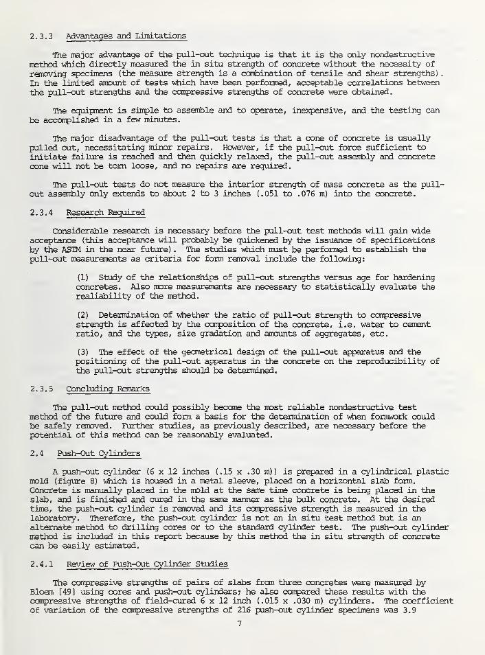
2.3.3 Advantages and Limitations
The major advantage of the pull-out technique is that it is the only nondestructive
method which directly measured the in situ strength of concrete without the necessity of
removing specimens (the measure strength is a combination of tensile and shear strengths)
.
In the limited amount of tests which have been performed, acceptable correlations betweenthe pull-out strengths and the compressive strengths of concrete were obtained.
The equipment is simple to assemble and to operate, inexpensive, and the testing can
be accomplished in a few minutes.
The major disadvantage of the pull-out tests is that a cone of concrete is usuallypulled out, necessitating ininor repairs. However, if the pull-out force sufficient toinitiate failure is reached and then quickly relaxed, the pull-out assembly and concretecone will not be torn loose, and no repairs are required.
The pull-out tests do not measure the interior strength of mass concrete as the pull-out assembly only extends to about 2 to 3 inches (.051 to .076 m) into the concrete.
2.3.4 Research Required
Considerable research is necessary before the pull-out test methods will gain wideacceptance (this acceptance will probably be quickened by the issuance of specificationsby the ASTM in the near future) . The studies which must be performed to establish thepull-out measurements as criteria for form removal include the following:
(1) Study of the relationships of pull-out strengths versus age for hardeningconcretes. Also more measurements are necessary to statistically evaluate therealiability of the method.
(2) Determination of whether the ratio of pull-out strength to compressivestrength is affected by the composition of the concrete, i.e. water to cementratio, and the types, size gradation and amounts of aggregates, etc.
(3) The effect of the geometrical design of the pull-out apparatus and thepositioning of the pull-out apparatus in the concrete on the reproducibility ofthe pull-out strengths should be determined.
2.3.5 Concluding Remarks
The pull-out method could possibly become the most reliable nondestructive testmethod of the future and could form a basis for the determination of when formwork couldbe safely removed. Further studies, as previously described, are necessary before thepotential of this method can be reasonably evaluated.
2.4 Push-Out Cylinders
A push-out cylinder (6 x 12 inches (.15 x .30 m) ) is prepared in a cylindrical plasticmold (figure 8) which is housed in a metal sleeve, placed on a horizontal slab form.
Concrete is manually placed in the mold at the same time concrete is being placed in theslab, and is finished and cured in the same manner as the bulk concrete. At the desiredtime, the push-out cylinder is removed and its compressive strength is measured in thelaboratory. Therefore, the push-out cylinder is not an in situ test method but is analternate method to drilling cores or to the standard cylinder test. The push-out cylindermethod is included in this report because by this method the in situ strength of concretecan be easily estimated.
2.4.1 Review of Push-Out Cylinder Studies
The compressive strengths of pairs of slabs from three concretes were measured byBloem [49] using cores and push-out cylinders; he also compared these results with thecompressive strengths of field-cured 6 x 12 inch (.015 x .030 m) cylinders. The coefficientof variation of the compressive strengths of 216 push-out cylinder specimens was 3.9
7

percent compared with 6.0 percent for an equal number of core specimens; the coefficientof variation for the field cured specimens was 2.4 percent. The compressive strengthsdetermined with the push-out cylinders were about 7 percent higher than those strengthsobtained with cores. Bloem concluded "that push out cylinders cast in the slabs provideda fairly reliable measure, relatively, of core strengths." He also stated the "field-cured cylinders may provide useful information but do not quantitatively reflect corestrength.
"
2/Richards—' has also found that the pull-out cylinder method gives an accurate estimation
of the in situ compressive strength of concretes.
2.4.2 Advantages and Limitations
The push-out cylinder method yields a closer determination of the in situ compressivestrength of concrete than field cured or laboratory cured specimens, and test specimenscan be more easily obtained than by drilling cores. This could be a reliable method todetermine when the formwork can be safely removed.
To obtain accurate determinations of the compressive strengths of the push-out cylinders,they will usually be tested in a laboratory. Therefore, verification of safe times toremove forms will not be immediately available. Furthermore, concrete is manually placedin the push-out cylinder and therefore, these specimens may not be consolidated to thesame extent as the bulk concrete, which can result in a slight difference in compressivestrengths. The push-out cylinder method is probably only applicable to testing horizontallylaid concrete slabs. Removal of the push-out cylinders will leave relatively large cavitieswhich must be filled.
2.4.3 Research Required and Concluding Remarks
The push-out cylinder methods appears to be a viable alternate to drilling cores orto field cured specimens for estimating the in-situ compressive strength; therefore,little research is needed. The push-out cylinder method should be included in a test pro-gram and the compressive strengths obtained could be used as the reference values.
2.5 Ultrasonic Pulse Velocity Method
Several types of nondestructive test methods have been developed based on wave propagationprinciples (often collectively termed sonic test [12] ) such as the measurement of resonantfrequencies [50-52] , acoustic pulse velocities [53] , seismic velocities [54] , and ultrasonicpulse velocities [11, 12, 55, 56] . The ultrasonic pulse velocity is by far the mostwidely accepted vibrational method for field use and is one of the most universally usednondestructive test methods for assessing the quality of concrete. Only this method willbe discussed in detail.
2.5.1 Principle of the Ultrasonic Pulse Velocity Method
The ultrasonic pulse velocity method is based on measuring the travel time of anultrasonic pulse passing through concrete. The pulse is generated by an electro-acoustictransducer and picked up by a transducer and amplified before being presented on a cathoderay oscilloscope for analysis. The time of travel of the pulse is measured electronically.The basic theory of the ultrasonic pulse velocity method is discussed in references 11-13
and 57. The velocity of the ultrasonic pulse propagating through concrete is dependent onthe density, elastic modulus, and Poisson's ratio of the concrete as well as the geometryof the tested specimen [12]
.
2/ These results of Richards are based on his private records.
8

At least three ultrasonic pulse velocity units are commercially available [13]
including the Ultrasonic Concrete Tester, the Soniscope and PUNDIT. The Ultrasonic
Concrete Tester has a testing range of only 7 feet (2.1 m) , whereas both the Soniscope
and PUNDIT can be used to test concrete having a thickness up to about 75 feet (22.7 m) .
Their respective operating frequencies are 150 kHz, 20 kHz, and 50 kHz.
2.5.2 Estimation of Strength of Concrete
Numerous investigators have attempted to correlate compressive and flexural strengths
of concrete with pulse velocity. Jones [11] has suggested that reasonably good correlation
(statistical data were not given) can be obtained between cube compressive strength andpulse velocity, provided the aggregates and mix proportions are kept constant. Theeffect of the type of aggregate and aggregate to cement ratio on the relationship betweenpulse velocity and compressive strength is illustrated by figures 9 and 10 (from references
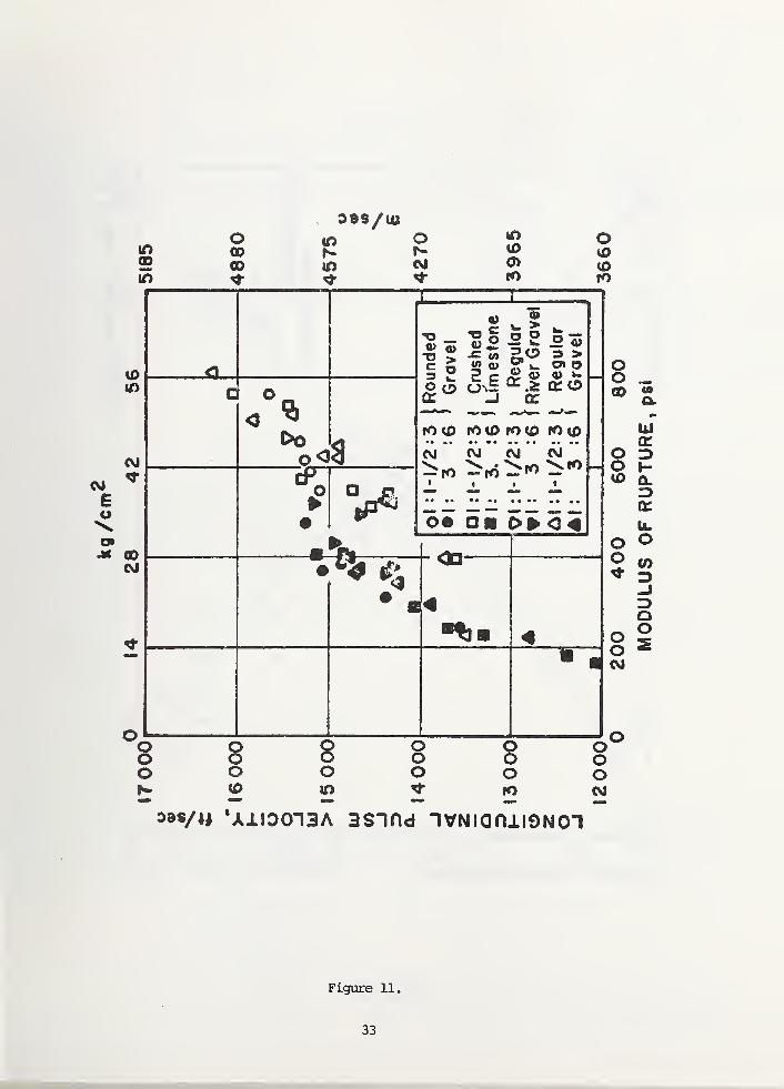
11 and 13) . Jones and Gaffield [59] have also found that the relationships betweenflexural strengths and pulse velocities are dependent on the aggregate:cement ratio, as
indicated in figure 11. According to Jones [11] , some researchers have establishedrelations between pulse-velocity and compressive strength. These relations enable thestrength of structural concrete to be predicted to within 20 percent. However, to obtainthis accuracy, corrections must be made for the type of cement, mix-proportions andcuring conditions. (These studies were performed under optimum laboratory conditionsand, probably, under normal field conditions much higher variations in strength predictionscould be anticipated) . Kaplan [59] also found that the relationships between the pulsevelocity and the flexural or compressive strengths are influenced by the type of aggregateand the mix proportions, as well as the degree of consolidation [60]
.
Whitehurst [61] performed tests on a series of 180 prisms prepared from four portlandcements, one type of aggregate, with three different water to cement ratios and threetypes of curing. He found that no usable correlation between either compressive orflexural strength and pulse velocity could be established. Parker [62] made a comparisonof pulse velocities and compressive strengths on standard cylinders made from only onetype of aggregate but containing cement from several sources and a variety of admixtures.His analysis of the total data indicated that at the 95 percent confidence level theestimated compressive strengthuof 4440 psi (30.7 MN/m^) concrete ranged from about 2100to 6000 psi (14.5 to 41.8 MN/m )
.
2.5.3 Determination of Formwork Removal Times
Similar to strength, the velocity of pulses passing through concrete increases withage. At early ages the curve relating pulse velocity with age has a sharp ascent, butafter about seven days it reaches a plateau. Malhotra [63] briefly studied the relationshipbetween compressive strength of concrete at early ages and ultrasonic pulse velocity, andsuggested that possibly the ultrasonic pulse velocity method could be used to determineformwork removal times. Kaplan [64] , however, found that the ratio of pulse velocity tocompressive strength changes with age, with the greatest change taking place within thefirst week. Furthermore, Rushing and Burt [65] found little correlation between thepulse velocity and the compressive strength of 7-day old concrete. Therefore, thisauthor feels that the ultrasonic pulse velocity method cannot be used with confidence todetermine form removal times.
2.5.4 Advantages and Limitations
Ultrasonic pulse velocity methods are excellent for determining the uniformity ofconcrete and are a definite asset in quality control. The testing procedures have beenstandardized by ASTM [66] and several types of test apparatus are commercially available.
A large number of variables affect the relationships between the strength of concreteand its pulse velocity. Some of these variables have been identified in Sections 2.5.2and 2.5.3, other important factors having an affect are [63]:
(1) Smoothness of the concrete surface at contact point
9

(2) Path length
(3) Moisture condition of concrete
(4) Temperature of concrete
(5) Presence of reinforcing steel.
Therefore, the use of ultrasonic pulse velocity or any dynamic method to predict thecompressive or flexural strengths of concrete is not recommended.
2.5.5 Research Required
The ultrasonic pulse velocity should only be considered in combination with anothernondestructive test method (see Sections 3 and 4)
.
2.5.6 Concluding Remarks
Probably the best concluding remarks regarding strength prediction from the completevariety of wave propagation methods are those stated by Jones [67]
:
"In spite of some of the promising results of the early investigations, it mustbe concluded that no general relation has been found between the dynamic modulus ofelasticity and its flexural or compressive strength". (This statement still holdsif one substitutes "pulse velocity" for "dynamic modulus of elasticity".)
Several investigators have advocated [63, 68-70] the use of the ultrasonic pulsevelocity method as a standard test in its own right. This author agrees with the opinionexpressed by Whitehurst [71]
:
"In conclusion, it may be stated that none of the several sonic test availableto the investigator is in any way a substitute for other tests normally performed onconcrete. . . .They constitute no cure-all for the problems of the concrete testingengineer, but do constitute a valuable addition to the techniques available to him."
This certainly applies to the determination of formwork removal times.
2.6 Predictions of Strength Development by Maturity and Equivalent Age
Several investigators [72-75] have suggested that the compressive strength of aconcrete can be related to its maturity, where maturity is defined by
E(e + 10°) At (1)
where 6 is the instantaneous temperature in °C of the concrete and At is the time incrementat this temperature.
An important postulate of this theory is that samples of the same concrete will haveequal compressive strengths if their maturities are the same, regardless of their temperaturehistories. Sadgrove [76, 77] has measured the compressive strengths of a concrete curedat ages between 5 hours to 28 days, at constant temperatures in the range of 1° to 45°C.He observed that a good relationship was obtained for the more mature concrete (more than3 days old) , however, there was considerable scatter at low maturities. The results areillustrated in figure 12, where compressive strength is plotted versus maturity equivalent.(The maturity equivalent is the maturity divided by 30°C and expressed as days at 20 °C)
.
To reduce this scatter an empirical factor F, related to temperature, was developed bywhich the actual age at a specific temperature is expressed in terms of age at 20 °C. TheF factor is calculated by the equation
F = (9 + 16°C)2
(2)36
where 9 is the instantaneous temperature, with the constraint that 0 cannot be lessthan -10 °C.
10

The summation of the product of the F factor and the increments of time associated
with each F factor, i.e.
Z (F • AT) (3)
is termed the equivalent age and is expressed in days at 20 °C. Replotting the values of
compressive strength of figure 12 versus equivalent age, figure 13, gave better agreement
at early ages. Sadgrove suggested that compressive strengths of concretes less than 3
days equivalent age should be predicted on the basis of equivalent age, while the strength
of older concretes should be estimated using the maturity equivalent.
2.6.1 Prediction of Formwork Removal Times
Weaver [78] has developed a method of predicting the temperature history of a hydrating
concrete element that considers biaxial heat flow, and constant ambient temperature.
Based on this method, he has also developed a computer program which predicts the temperature
of a hydrating concrete element at given time intervals. The equivalent age increment of
each time interval is calculated and the total equivalent age determined. This theoretical
value is then compared with the experimental equivalent age required for a given concreteto reach specific compressive strengths. When the equivalent age required for the concrete
to reach a specific compressive strength is experimentally determined, the actual age is
tabulated and a series of form removal times (striking times) are tabulated [79]
.
In addition to the data required for the temperature prediction, data for the concretedesign strength and the desired strength levels, for which times are to be predicted,must be inputed into the computer program. A series of striking times prepared by Weaverand Sadgrove [6, 8] are given in table 1 for strength D, the level at which no damage toconcrete would occur by frost, and for strengths corresponding to 33 percent and 66percent of the design strength specified in the British Code of Practices [80] . Atpresent, a version of the striking time tables conforming to acceptable practices in theUnited States is being prepared by Weaver and Sadgrove.
2.6.2 Advantages and Limitations
Based on the maturity equivalent and equivalent age methods, the time for hardeningconcretes to reach specified compressive strengths can be estimated. If strength criteriafor form removal are developed, these methods should be useful in determining when theformwork can be safely removed. These methods do not cause any damage to the concretespecimen and require little on-site preparation.
The use of the maturity equivalent and the equivalent age methods necessitates thatboth the properties of the concretes and the placing conditions, which affect heat flow,be well characterized; the potential compressive strength of the concrete at the standardage must also be known. Highly trained personnel and computer prograiiming are necessaryto prepare those tables of form removal times.
2.6.3 Research Required
Before the maturity equivalent and equivalent age methods may be widely used in theUnited States for determining safe form removal times, extensive evaluations need to beperformed and tables developed which consider:
(1) wide range of ambient temperatures
(2) range of concrete designs including type of cement, type of and graduationof aggregate, and water to cement ratio
(3) different types of concrete; insulating, lightweight, dense, etc.
The statistical reliability of the maturity equivalent and the equivalent age methodshas not been ascertained and needs to be investigated before these, methods may be incorpo-rated into standards and codes. Possibly, the maturity equivalent and equivalent age
11

Table 1 (from reference 77)
STRIKING TIMES IN HOURS AFTER PLACING-Ordinary Portland Cement
CEMENTCONTENT 330 kg/m3 380 kg/m3 380 kg/m3 450 kg/m3 450 kg/m3 490 kg/m 1
CHARAC-TERISTICSTRENGTH 22.5 N/mm1 22.5 N/mm3 30.0 N/mm 3 30.0 N/mm1 37.5 N/mm 1 37.5 N/mm 1
G OA O 33% 66% O 33% 66% D 33% 66% D 33% 66% D 33% 66% D 33% 66%.
-5
0 1 55 245 1 50 240 115 240 110 240 85 200 85 200
18.9 5 88 140 476 88 140 472 64 140 452 64 140 452 52 116 432 48 116 432
10 60 93 309 57 93 309 42 93 297 42 90 294 33 75 282 33 75 282
15 42 66 219 421
63 219 30 63 210 30 63 207 24 54 198 21 51 198
-5
0 140 230 1 35 225 100 225 95 220 70 180
.. .
70 180
10.0 5 80 132 464 80 128 460 56 128 440 52 124 436 40 104 416 40 100 416
10 54 87 303 51 84 300 36 84 285 36 81 282 27 66 270 27 63 270
15 39 60 213 36 60 210 27 60 201 27 57 198 21 45 189 21 45 189
-5
- .
0 120 208 116 204 80 204 72 196 52 1 56 52 1 52
6.5 5 69 120 447 66 114 441 48 114 420 42 108 414 33 87 396 33 84 39010 48 78 292 44 74 286 34 74 274 30 68 266 24 56 256 24 52 252
15 36 56 206 34 52 202 26 52 192 24 48 186 20 40 178 20 38 176
1
-5
0 105 192 99 183 66 1 83
-
57 171 42 1 32 663 39 1 26 654
5.0 5 62 110 434 58 104 426 42 104 406 38 94 394 30 74 376 28 68 370
10 44 72 282 41 67 276 32 67 262 29 60 253 24 49 242 23 45 236
15 35 53 199 32 49 194 26 49 184 24 44 176 20 37 168 19 34 164
-5 52 220 48 200
0 81 156 72 144 51 144 657 42 123 633 33 90 600 33 81 585
3.4 5 52 90 404 48 82 392 36 82 370 32 70 352 28 56 334 26 50 322
10 40 62 261 37 57 250 30 57 237 27 49 222 23 41 211 22 38 201
15|
33 48 183 31 44 174 25 44 165 23 39 152 20 34 144 20 31 136
f
-5i 68 156 56 116 40 116 36 76 32 60 28 52
0 48 81 570 42 69 525 36 69 489 30 54 420 27 45 393 24 42 345
2.0 5 40 60 316 36 52 286 30 52 266 28 44 218 24 38 202 22 36 170
10 35 50 201 33 45 179 27 45 167 25 38 133 22 34 124 21 32 105
15 32 43 142 29 39 125 25 39 118 23 34 95 21 31 90 20 29 78
-5 48 76 40 64 32 64 28 48 576 24 44 512 24 40 356
0 42 60 429 36 51 357 30 51 321 27 42 213 24 39 189 21 36 141
1.3 5 36 52 238 34 46 196 28 46 180 26 40 130 22 34 120 22 32 100
10 34 47 163 31 42 138 26 42 129 24 36 101 21 32 95 20 30 83
,5 32 43 127 29 38 110 25 38 104 23 33 85 20 30 81 19 28 72
SECTION 500 * 300
PLACING TEMP 10;
C
Key to column entries
G: Formwork conductance (W/m 1 degC)
OA: Ambient temperature (°C)
D: Resistant to damage
33%: 33% of characteristic strength reached
66%: 66% of characteristic strength reached
12

methods can be used to predict other mechanical properties of concrete, such as flexural
and shear strengths; this also should be investigated.
2.6.4 Concluding Remarks
The maturity equivalent and equivalent age are attractive methods for determining
when forms may be removed. However, in both methods the concrete mix design must be
known to calculate the strength as a function of age and the calculated strengths could
be grossly different than the in-situ strengths if the mix design is changed, e.g. by the
addition of more mix water. Therefore, the predicted in situ strength obtained from
these methods should be verified by another nondestructive test such as the pull-out or
the rebound hammer, methods.
3. COMBINATION OF NONDESTRUCTIVE TESTS
To predict the compressive strength of in situ concrete more accurately, two differentnondestructive tests are performed consecutively. The most popular combination has beenthe ultrasonic pulse velocity method in conjunction with the rebound hammer [81] . Othercommon combinations are the ultrasonic pulse velocity method and the measurement of thedamping constant of concrete [82] , and the ultrasonic pulse velocity and pulse attenuationmethods [83] . These latter two combinations are essentially laboratory research techniquesand therefore will not be discussed further.
3.1 Combination of Ultrasonic Pulse Velocity and Rebound Hammer Methods
This combination of nondestructive tests has been used in Europe, primarily, withthe most exhaustive studies being carried out by Facaoaru [84-87] . In this combinedapproach, ultrasonic pulse velocity measurements are made on in situ concrete, while therebound number is measured with the Schmidt Rebound Hammer. The pulse velocity andrebound number are then combined to yield a linear regression equation with the independentvariable being compressive strength [82] . It is believed that the regression equationshould give a more accurate estimate of compressive strength than given by either of theindividual measurements, i.e. pulse velocity or rebound number.
Facaoaru [84] has developed calibration charts for standard concrete mixes fromwhich the compressive strengths can be estimated when the pulse velocities and reboundnumbers are known. Correction factors have also been developed to be used in the case ofnonstandard concrete mixes.
This combined method has been used often in Romania to estimate the compressivestrength of in-situ concrete, with improved accuracy [84-86] . Based on his experiences,Facaoaru contends that by using the combined method, the following accuracy in predictionsof compressive strengths can be realized:
(1) When composition is known and test specimens or cores are available forcalibration purposes, accuracy is within 10 to 15 percent.
(2) When only the composition of the concrete is known, accuracy is within 15to 20 percent.
(3) When neither the composition is known nor test specimens or cores areavailable, accuracy is within 20 to 30 percent.
This suggests that for case (3) , the combined method gives no better prediction ofthe compressive strength than can be obtained by measuring only the ultrasonic pulsevelocity or only the rebound number; in case (2) , the improvement is marginal. Therefore,only when the concrete is well characterized is this combined method better than theindividual nondestructive methods.
13

3.2 Concluding Remarks
The combined method,, ultrasonic pulse velocity and rebound hammer, involves relativelysimple techniques which can be used on in situ concrete. However, to gain any significantincrease in accuracy, the composition of the concrete should be known and specimens for
calibrating the respective methods should be available.
This review did not disclose any reported uses of combined nondestructive testmethods to determine when formwork could be safely removed (research requirements are-
discussed in Section 4)
.
4. PROPOSED RESEARCH AND RECaVMENDATIONS
The individual nondestructive test methods (Section 2) do not appear to form anadequate basis for the accurate prediction of the in situ strength of either immature ormature concrete. (The push-out cylinder is not being regarded as an authentic nondestructivetest. It is an alternative to cores, and can provide an effective calibration method fornondestructive test methods.) Therefore, it is recommended that formwork removal timesshould not be based upon the results of individual nondestructive test methods. Further-more, it is recommended that detailed strength requirements, with reasonable statisticaltolerances, be developed upon which formwork removal times can be based.
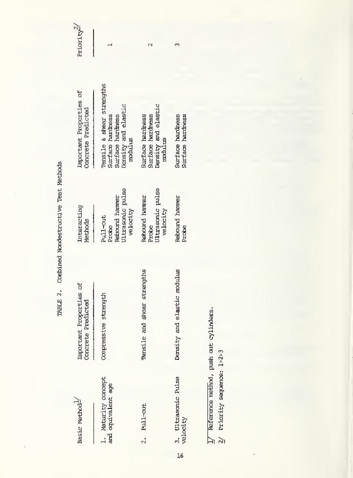
This author believes that a combined nondestructive test approach (as discussed inSection 3) has promise and should be investigated further. The proposed combinations arelisted in table 2, in order of decreasing importance. The priority sequence is based oncomparing the important properties of concrete predicted by the individual tests. Forexample both the maturity concept (or equivalent age concept) and the pull-out methodgive predictions of strength properties of concrete and the combination of these methodsshould give a better prediction of the compressive strength of concrete than the individualmethods. The results of the two methods can be combined in a linear regression equationof the form:
a = Aa + BP + C (4)c p
where ac is the estimated compressive strength from the combined methods apis the compressive strength estimated by the maturity concept (or equivalentage concept) , P is the pull-out strength; and A,B and C are empirically de-termined constants.
Neither the ultrasonic pulse velocity nor the rebound hammer give a direct prediction ofthe strength properties of concrete. Therefore, the combination of these methods can notbe expected to give a significantly better prediction of the compressive strength thanthe individual methods. Furthermore, using the probe as the interacting method willprobably not improve the accuracy of the combined method. The push out cylinder methodshould be used as the reference method and also for calibration purposes.
The proposed research project should accomplish the following tasks:
(1) Determine the accuracy of the combined methods in predicting the compressivestrength of hardening concretes, especially at common formwork removal times.
(2) Determine whether the combined methods are more accurate than the individualmethods.
(3) Determine the effects of variation in concrete composition, concrete con-solidation, ambient temperature, the formwork itself, and the other variablesnoted in Section 2, on the accuracy of the individual and also the combinedmethods.
14

(4) Develop criteria upon which formwork removal times can be based. Possibly,the results of the combined nondestructive test method could constitute thecriteria for basing formwork removal times.
(5) Investigate the possibilities of predicting mechanical properties besidescompressive strengths by the individual and combined nondestructive test methods.For example, the flexural and shear strengths of a concrete at the time offormwork removal may be more important than its compressive strength.
5. SUMMARY AND CONCLUSIONS
Individual and combined nondestructive test methods have been critically reviewed aspotential methods for determining formwork removal times. It has been recommended thatfuture research emphasize combined methods. The most universally used combined method,ultrasonic pulse velocity and rebound number measurements, does not give an adequateestimation of the in-situ strength of concrete; other combinations have been proposedwhich should give improved estimates.
Regardless of the nondestructive test method chosen to determine formwork removaltimes (or to estimate the in situ strength of concrete, at any age) , the effectiveness ofa method depends directly on how much is known about the tested concrete.
15
CO -Pen tn to
M co co to
^ i2 x! io
'H>2 IH
"H^
^ tO CO CO CO
CO COCO CO
IIII
884-1 4-1
9 §CO CO
a
I
19
0)
T3
•H
U
Ia*i-l -H
16

6. REFERENCES
1. J. Feld, "Construction Problems: Fonnwork Failures", Chapter 5, pp. 95-114, 15
Lessons from Failures of Concrete Structures, ACI Monograph No. 1, 1964; and thereference therein.
2. E. V. Leyendecker and S. G. Fattal, "Investigation of the Skyline Collapse in Fairfax
County, Virginia", NBSIR 73-222, June 1973,
3. Symposium on Nondestructive Testing of Concrete and Timber, Institution of CivilEngineers, London, 1969.
4. RILEM International Symposium on Nondestructive Testing of Materials and Structures,
Paris, 1954.
5. Nondestructive Testing of Concrete, HRB Record No. 378, 1972.
6. New Developments in Nondestructive Testing of NOnmetallic Materials, RILEM IlndInternational Symposium, Romania, 1974.
7. S. Li and J. E. Russell, "The State-of-the-Art of Nondestructive Evaluation inConcrete Technology", 7th Symposium on Nondestructive Evaluation of Components andMaterials in Aerospace Weapons Systems and Nuclear Applications, Proceedings ofAmerican Society for Nondestructive Testing, South Texas Section, 1969.
8. S. T. Li, V. Ram Akrishman and J. E. Russell, "Where Standards Nondestructive! Testingof Concrete and Whither?" Int. J. of Nondestructive Testing, 2, 281 (1970)
.
9. V. M. Malhotra, "Nondestructive Methods for Testing Concrete", Mines Branch Monograph815, Ottawa, 1968.
10. R. Jones, "A Review of the Nondestructive Testing of Concrete, Paper 1A, Symposium onNondestructive Testing of Concrete and Timber, Institution of Civil Engineers, London,
1969.
11. R. Jones, "Nondestructive Testing of Concrete", Cambridge University Press, 1962.
12. E. A. Whitehurst, "Evaluation of Concrete Properties from Sonic Tests", ACI MonographNo. 2, 1966.
13. V. M. Malhotra, "Nondestructive Methods for Testing Concrete, ACI Monograph, in press.
14. A. Voellmy, "Examination of Concrete by Measurement of Superficial Hardness", RILEMInternational Symposium on Nondestructive Testing of Materials and Structures,Paris, France, Volume 2, pp. 323-336, 1954.
15. T. R. Cantor, "Status Report on The Windsor Probe Test System", presented to HighwayResearch Board Committee A2-03, at 1970 Annual Meeting of Highway Research Board,Washington, D.C., Januar 1970.
16. S. Freedman, "Field Testing of Concrete Strength", Modern Concrete 14 (2), 31 (1969)
.
17. S. M. Law and W. T. Burt, "Concrete Probe Strength Study", Louisiana Department ofHighways Research Report 44, 1969.
18. R. D. Gaynor, "In-Place Strength of Concrete - A Comparison of Two Test Systems",National Ready-Mix Concrete Association Technical Information Letter NO. 272, 1969.
19. H. T. Ami, "Impact and Penetration Tests of Portland Cement Concrete", FederalHighway Administration Report NO. FHWA-RD-73-5, 1972.
17

20. H. T, Ami, "Impact and Penetration Tests of Portland Cement Concrete", inNondestructive Testing of Concrete, HRB Record 378, pp. 55-67, 1972.
21. V. M. Malhotra and K. Painter, "Evaluation of the Windsor Probe Test for EstimatingCompressive Strength of Concrete", Mines Branch Investigation Report IR 71-50,
Ottawa, Canada, 1971.
22. J. R. Keeton and V. Hernandez, "Calibration of Windsor Probe Test System forEvaluation of Concrete in Naval Structures;", Technical Note N-1233, Naval CivilEngineering laboratory, Port Hueneme, California, 1972.
23. A. T. Shore, "Properties of Hardness in Metals and Materials", Proceedings ASTM, XI,
733 (1911).
24. E. Schmidt, "Der Beton-Prufhammer" , Schweiz Bauzeitung, July 15, 1960.
25. E. Schmidt, "Versuche mit dem neuen Beton-Prufhammer zur Qualitasbestimmung des Betons"
,
Schweitzer Archiv fur Angewandete Wissenschaftund technik, Drub and Verland, No. 5,
(1951)
.
26. E. Schmidt, "A Nondestructive Concrete Test", Concrete 59 (8), 34 (1951).
27. L. Brunarski, "Draft Instructions on the Application of Selerometric, Ultrasonic andResonance Methods", Bulletin RTLEM No. 27, 121 (1965).
28. I. Facaoaru, "L" experiende del 1' application des normes roumaines provisoires pour ladetermination de la resitance du beton a I'aide du Solerometre Schmidt", BulletinRILEM No. 27, 121 (1965)
.
29. British Standards Institution, "Recommendations for Nondestructive Methods of Test forConcrete", Part 4. Surface Hardness Methods, BS 4408: Part 4; 1971.
30. P. H. Petersen and U. W. Stoll, "Relation of Rebound-Hammer Test Results to SonicModulus and Compressive-Strength Data", Proceedings HRB, 34, 387 (1955).
31. Discussion of Reference 30, by P. Klieger, Proceedings HRB, 34_, 392 (1955).
32. C. A. P. Boundy and G. Hondros, "Rapid Field Assessment of Strength of Concrete byAccelerated Curing and Schmidt Rebound Hammer", J. Am. Cone. Inst., 61, (1), 11(1964): Discussion J. Am. Cone. Inst., 61 (9), 1185 (1964).
33. D. J. Victor, "Evaluation of Hardened Field Concrete with Rebound Hammer", IndianCone. J., 37 (11), 407 (1963).
34. G. W. Greene, "Test Hammer Provides New Method of Evaluating Hardened Concrete", J.
Am. Cone. Inst., 26 (3), 249 (1954).
35. Discussion of Reference 33, J. Am. Cone. Inst., 27 (4), 256 (1955).
36. L. J. Mitchel and G. G. Hagland, "Investigation of the Impact-Type Concrete TestHammer", HRB Bulletin 305, 14 (1961).
37. C. H. Williams, "Investigation of the Schmidt Concrete Test Hammer", MiscellaneousReport No. 6-267, U. S. Army Engineer Waterways Experiment Station, Vicksburg,Mississippi, 1958.
38. G. A. Erickson, "Investigation of the Impact-Type Concrete Test Hammer, Model 11",
Concrete Laboratory Report No. C-928, Division of Engineering Laboratories, Dept. ofthe Interior, Denver, 1959.
18

39. J. Kolek, "Nondestructive Testing of Concrete by Hardness Methods, Paper 3A, Symposium
on Nondestructive Testing of Concrete and Timber, Institution of Civil Engineers,
London, 1969.
40. B. G. Skramtajew, "Deternrijiing Concrete Strength for Control of Concrete in Structures",
J. Am. Cone. Inst., 34, 285 (1938).
41. T. Yoshida, "Studies on Concreting in Freezing Weather, Part 2", Department of CivilEngineering, Tokyo Imperial University, January 1942.
42. B. Tremper, "The Measurement of Concrete Strength by Embedded Pull Out Bars",
proceedings of the annual meeting, ASTM, 880 (1944)
.
43. P. K. Hansen, "Method for Testing the Strength of the Material of Cast Structures,Particularly Concrete Structures", U. S. Patent No. 3,541,845 (1970)
.
44. M. Teeni, "Testing of Concrete", U. S. Patent No. 3,640,126 (1972).
45. F. Kaindl, "Method and Apparatus for Early Strength Testing of In-Place Concrete", U.S.
Patent Application Serial No. 368 325, filed June 1973.
46. 0. Richards, "Pull Out Strength Tests of Concrete", paper presented at the ResearchSession, 1972 Annual Meeting of ACI, Dallas, Texas.
47. V. M. Malhotra, "Evaluation of the Pull Out Test to Determine Strength of In-SituConcrete", Mines Branch Investigation Report IR 72-56, Ottawa, 1972.
48. T. P. Tassios and C. A. Demiris, "Standard Nails Extraction, A New Method for Concrete'sStrength Determination", Natural Technical University of Athens, Athens, Greece, 1970.
49. D. L. Bloem, "Concrete Strength in Structures", J. Am. Cone. Inst., 65 (3), 176
(1968)
.
50. T. C. Powers, "Measuring Young's Modulus of Elasticity by Means of Sonic Vibrations"ASTM 38 (Part II) , 460 (1938)
.
51. F. B. Hornibrook, "Application of Sonic Method to Freezing and Thawing Studies ofConcrete", ASTM Bulletin No. 101, 5 (1939)
.
52. Standard Method of Test for Fundamental Transverse, Longitudinal and TorsionalFrequencies of Concrete Specimens. ASTM Designation C215-60.
53. G. Swift and W. M. Moore, "Investigation of Applicability of Acoustic Pulse VelocityMeasurements to Evaluation of Quality of Concrete in Bridge Decks" in NondestructiveTesting of Concrete, HRB Record 378, pp. 29-39, 1972.
54. W. E. Brownfield, "Nondestructive Testing of Concrete by Wave Velocity Methods: ALaboratory and Field Study", in Nondestructive Testing of Concrete, HRB Record 378,
pp. 12-19, 1972.
55. W. J. Cheesman, "Dynamic Testing of Concrete with the Soniscope Apparatus", ProceedingsHRB, 29, 176 (1949).
56. R. Jones, "The Effect of Frequency on the Dynamic Modulus and Damping Coefficient ofConcrete", Mag. of Cone. Res., 9 (26), 69 (1957).
57. J. Anderson, P. Nerenst, and N. M. Plum, "The Nondestructive Testing of Concrete, withSpecial Reference to the Wave-Velocity Method", Building Research Report No. 3, TheDanish National Institute of Building Research, Copenhagen, 1950.
58. R. Jones and E. N. Gatfield, "Testing Concrete by an Ultrasonic Pulse Technique", USIRRoad Research Technical Paper No. 34, London.
19
59. M. F. Kaplan, "Ultrasonic Pulse Velocity, Dynamic Modulus of Elasticity, Poisson's Ratioand The Strength of Concrete Made with Thirteen Different Coarse Aggregates" , RILEMBulletin No. 1, 58 (1959)
.
60. M. F. Kaplan, "Effects of Incomplete Consolidation on Compressive and Flexural Strength,Ultrasonic Pulse Velocity, and Dynamic Modulus of Elasticity of Concrete," J. Am. Cone.
Inst., 56 (3), 853 (1960).
61. E. A. Whitehurst, "Dynamic Testing of Concrete Evaluated", Civil Eng. 12, 863 (1951).
62. W. E. Parker, "Pulse Velocity Testing of Concrete", Proceedings ASTM, 53, 1033 (1953).
63. V. M. Malhotra, "Ultrasonic Pulse Velocity Method" in Nondestructive Methods for TestingConcrete, ACI SP, in press.
64. M. F. Kaplan, "The effects of age and water/cement ratio upon the relation betweenultrasonic pulse velocity and compressive strength of concrete", Mag. of Cone. Res.,
11 (32), 85 (1959).
65. H. B. Rushing and J. 0. Burt, "Nondestructive Testing of Concrete", Research ReportNo. 51, Louisiana Department of Highways; NTIS PB-204.
66. Tentative Method of Test for Pulse Velocity Through Concrete, ASTM Designation C597-68T.
67. Page 33 of reference 11.
68. R. G. Drysdale, "Variation of Concrete Strength in Existing Buildings", Mag. of Cone.Res., 25 (85), 201 (1973).
69. N. J. Lowe, "What's Wrong with our Codes?" Symposium on Quality Control, Cement andConcrete Association, London, 1964.
70. A. R. Collins, "Methods of Specifying Concrete" Proceedings of the Symposium on MixDesign and Quality Control of Concrete, Cement and Concrete Association, London,
pp. 488-502, 1954.
71. Page 82 of reference 12.
72. R. W. Nurse, "Steam Curing of Concrete", Mag. of Cone. Res., 1 (2) 79 (1949).
73. A. G. A. Saul, "Principles Underlying the Steam Curing of Concrete", Mag. of Cone.Res., 2 (6), 127 (1951).
74. S. G. Bergstrom, "Curing Temperature, Age and Strength of Concrete", Mag. of Cone.Res. , 5 (14) , 61 (1953)
.
75. J. M. Plowman, "Maturity and the Strength of Concrete", Mag. of Cone. Res., 8^ (22), 13
(1956)
.
76. B. M. Sadgrove, "The Strength and Deflection of Reinforced Concrete Beams Loaded atEarly Age", Construction, Industry Research and Information Association (London)
,
Technical Note 31, 1971.
77. B. M. Sadgrove, "Prediction of Strength Development in Concrete Structures", presentedat the 54th Annual Meeting of the Transportation Research Board, Washington, D.C.,January 1975.
78. J. Weaver, "Temperature development in hydrating concrete," Ph.D. Thesis, Universityof London, 1971.
20

79. J. Weaver and B. M. Sadgrove, "Striking times of formwork - tables of curing periods toachieve given strengths", Construction Industry Research and Information Association(London) , Report 36, 1971.
80. Draft British Code of Practice for the Structural Use of Concrete, The Council forCodes of Practice, British Standards Institution, 1969.
81. R. Jones and I. Facaoaru, "Analysis of Answers to a Questionnaire on the UltrasonicPulse Technique", RILEM Materials and Structures, 1 (5), 457 (1968).
82. J. G. Wiebenga, "A Comparison between Various Combined Nondestructive Testing Methodsto Derive the Compressive Strength of Concrete", Report No. B1-68-61/IHI.8, InstitutTNO Voor Bouwmaterialen en Bouwconstructies, Delft, Netherlands, 1968.
83. A. Galan, "Estimate of Concrete Strength by Ultrasonic Pulse Velocity and DampingConstant", J. Am. Cone. Inst., 6_4 (10), 678 (1967).
84. I. Facaoaru, "Nondestructive testing of concrete in Romania", Paper 4C, Symposium onNondestructive Testing of Concrete and Timber, Institution of Civil Engineers, London,1969.
85. I. Facaoaru, I. Dumitrescu, and L. Constaninescu, "Concrete Strength Extermination byNondestructive Combined Methods" RILEM Report, Achen, 41 (1966)
.
86. I. Facaoaru, I. Dumitrescu, and Gh. Stamate, "New Developments and Experience inApplying Combined Nondestructive Methods for Testing Concrete", RILEM Report, Varna,26 (1968).
87. I. Facaoaru, "Chairman's Report of the RILEM Committee on Nondestructive Testing ofConcrete", RILEM, Materials and Structures 2 (10), 253 (1969).
21

7. FIGURE CAPTIONS
Figure 1. Windsor Probe in operation.
Figure 2. Shapes and sizes of probes used with the Windsor Probe.
Figure 3. Device to measure length of probe extending from the surface of tested concrete.
Figure 4. Plot of probe heights versus compressive strengths, with 95 percent confidencelimits of the regression line (from reference 19)
.
Figure 5. Schmidt Rebound Hammer in operation.
Figure 6. Plot of rebound numbers versus compressive strengths, with 95 percent confidencelimits of the regression line (from reference 19)
.
Figure 7. Schematic of pull-out tester embedded in concrete.
Figure 8. Schematic of push-out cylinder in place.
Figure 9. Effect of type of aggregate on relationship between ultrasonic pulse velocityand compressive strength (from reference 13)
.
Figure 10. Effect of cement: irregular-river aggregate ratio on relationship betweenultrasonic pulse velocity and compressive strength (from reference 11)
.
Figure 11. Effect of type of aggregate and cement: sand:aggregate ratio on relationshipbetween ultrasonic pulse velocity and flexural strength (from reference11).
Figure 12. Plot of compressive strength versus maturity equivalent. Maturity is expressedas days at 20°C (from reference 77)
.
Figure 13. Plot of compressive strength versus equivalent age. Equivalent age is expressedas days at 20°C (from reference 77)
.
USCOMM-NBS-OC
22


Figure 2.
24

Figure 3.
25

Figure 4.
26

Figure 5.
27

COMPRESSIVE STRENGTH - PSI
Figure 6.
28

29


17.000
14000
kg /cm 2
280 420 560 700
2000 4000 6000 8000 10000
CUBE COMPRESSIVE STRENGTH, psi
4270
Figure 9.
31

oto
O
OCM<3"
ototo
OCO04
oCM
O
o1^
o10
09S/UJm Or>- cjto ^
oCM
oCM
\
N—#.3 \
_ 00 a°* > ^• ^ 2
to !?CM
— CM^J ^t^MD^ -. 1— 1 CJ CM tO
Vas
oototo
oooto
ooto o
0CD
OOO
\jQ.
V-/f\wCO H00w
REN
toSTI
O LJO >O CONT CO
UJ0 oc
0 a.
0ro Ou
OO UJO 03CM
U.
OOO
810to
3*VW 1 A1I0013A 3AVM IVNIOnilONOl
Figure 10.
32
go
in
Ooooo
33$/Wmin
CJ
GO
O
Oo
o
3
m
ro
o<0fO
r W '
O o (J™ 01.21
ro <D ro ro id
OJ cj oj
^ro ^ro^«>
3 >
ro to
cj"
\ro
Q6 DM C>» <3«
oo00
ooID
Oo
ooCJ
COo.
ua:z>
£L
a:
u.oCO
3Oo
ooo o
8o
ooo o
IO
oooCJ
3»VW ,A1IOOH3A 3S"10d TVNIQnil9N01
Figure 11.
33

Figure 12.
34


NBS-114A (REV. 7-73)
U.S. DEPT. OF COMM.BIBLIOGRAPHIC DATA
SHEET
1. PUBLICATION OR REPORT NO.
NBSIR 75-729
2. Gov't AccessionNo.
3. Recipient's Accession No.
4. TITLE AND SUBTITLE
NONDESTRUCTIVE TESTS TO DETERMINE CONCRETE STRENGTH - A
STATUS REPORT
5. Publication Date
6. Performing Organization Code
461.027. AUTHOR(S)
James R. Clifton8. Performing Organ. Report No.
NBSIR 7R-72Q9. PERFORMING ORGANIZATION NAME AND ADDRESS
NATIONAL BUREAU OF STANDARDSDEPARTMENT OF COMMERCEWASHINGTON, D.C. 20234
10. Project/Task/Work Unit No.
11. Contract/Grant No.
12. Sponsoring Organization Name and Complete Address (Street, City, State, ZIP)Building Safety SectionCenter for Building TechnologyNational Bureau of StandardsWashington, D.C. 20234
13. Type of Report & PeriodCovered
Final
14. Sponsoring Agency Code
15. SUPPLEMENTARY NOTES
16. ABSTRACT (A 200-word or less factual summary of most significant information. If document includes a significant
bibliography or literature survey, mention it here.)
Individual and combined nondestructive test methods have been critically reviewed aspotential methods to determine safe formwork removal times. The techniques reviewed arethe Windsor probe, the Schmidt Rebound Hammer, pull-out measurements, push-outcylinders, ultrasonic pulse velocity measurements, and the maturity and equivalent ageconcepts. The individual methods, themselves, do not give good estimates of the in situstrengths of concretes and it is recommended that future research emphasize combinedmethods.
A proposed research program which emphasizes combined nondestructive test methods hasbeen developed.
17. KEY WORDS (six to twelve entries; alphabetical order; capitalize only the first letter of the first key word unless a proper
name; separated by semicolons)
Compressive strength; concrete; flexural strength; footwork removal; nondestructivetesting; surface hardness
18. AVAILABILITY [^Unlimited 19. SECURITY CLASS(THIS REPORT)
21. NO. OF PAGES
1For Official Distribution. Do Not Release to NTIS
UNCL ASSIFIED
42
1
1 Order From Sup. of Doc, U.S. Government PrintingWashington. D.C. 20402. SD Cat. No. C13
Office 20. SECURITY CLASS(THIS PAGE)
22. Price
I !
Order From National Technical Information ServiceSpringfield, Virginia 22151
(NTIS)UNCLASSIFIED
USCOMM.DC 29042-P74