nonlinear analysis of fiber-reinforced composite laminates
TRANSCRIPT

Nonlinear Analysis of Fiber-ReinforcedComposite Laminates Subjected to
Uniaxial Tensile Load
WEN-PIN LIN*Department of Civil Engineering
Chinese Military Academy
Fengshan, Taiwan 830, ROC
HSUAN-TEH HU
Department of Civil Engineering
National Cheng Kung University
Tainan, Taiwan, 701, ROC
(Received August 7, 2000)(Revised July 6, 2001)
ABSTRACT: A nonlinear constitutive model together with a mixed failurecriterion for a single lamina is developed to simulate the behavior of compositelaminates under uniaxial tension. In the model, fiber and matrix are assumed tobehave elastic–plastic and the in-plane shear to behave nonlinear with a variableshear parameter. The damage onset for individual lamina is detected by a mixedfailure criterion, which is composed of Tsai–Wu criterion and maximum stresscriterion. After damage is taken place within the lamina, fiber and in-plane shear areassumed to exhibit brittle behavior and matrix to exhibit degrading behavior. Thismaterial model has been tested against experimental data and good agreementhas been obtained.
KEY WORDS: constitutive model, elastic–plastic, nonlinear, shear parameter,mixed failure criterion, post-damage mode.
INTRODUCTION
DUE TO LIGHTWEIGHT and high strength, the use of fiber-reinforced compositelaminate materials in aerospace industry or in applied engineering has increased
rapidly in recent years. In numerous cases involving the design of composite structures,there is a need for more refined analysis that takes into account phenomena such asprogressive cracking and inelastic or nonlinear deformation of the composite materials.
*Author to whom correspondence should be addressed.
Journal of COMPOSITE MATERIALS, Vol. 36, No. 12/2002 1429
0021-9983/02/12 1429–22 $10.00/0 DOI: 10.1106/002199802021463� 2002 Sage Publications

Such analysis is required not only to predict the deformational response, but also toprovide a method to evaluate the accurate stresses to be used in failure predictions.
Most of the advanced composite materials have organic matrices; therefore, there is asignificant nonlinear stress–strain behavior present in the transverse direction of laminaand particularly in shear deformation [1]. A significant number of macro-mechanicalmodels have been proposed to represent the constitutive relation of fiber-reinforcedcomposite materials such as nonlinear elasticity models [2,3], plasticity models [4–8], ordamage theory coupled with elasticity [9]. In addition, various failure criteria have alsobeen proposed to predict the onset of damage in single layer within the fiber-reinforcedcomposites. There are four types of failure criteria: (a) limit theories, (b) polynomialtheories, (c) strain energy theories, and (d) direct mode determining theories. The limittheories compare the value of each stress or strain component to a correspondingultimate value, such as maximum stress theory and maximum strain theory [10]. Thepolynomial theories use a polynomial in stress to describe a failure surface, such as Tsai–Wu failure criterion [11] and Hoffman failure criterion [12]. The strain energy theoriesattempt to use a nonlinear energy based criterion to define failure, such as Tsai–Hillfailure criterion [13]. Finally, the direct mode determining theories are usually withpolynomials in stress and use separate equations to describe each mode of failure, suchas Hashin failure criterion [14], Lee failure criterion [15] and Chang failure criterion [16].As for the post-damage process of individual lamina, there are two idealized types offailure modes defined in the previous study [5]; namely, brittle and ductile. For thebrittle mode, the material is assumed to give up its entire stiffness and strength inthe dominant stress direction as the damage is reached, whereas for the ductile mode thematerial remains its strength but loses its overall stiffness in the damage direction.
Obviously, a completely and rationally mechanical response analysis of individual layerwithin the laminate under loading must be included three parts; namely, pre-damageanalysis, damage onset determining, and post-damage analysis. In the pre-damage analysisthe proper constitutive model of lamina is a key tool to describe the real behavior ofindividual layer within the laminate under loading. In the previous study, it is assumedthat the fiber and matrix perform as elastic–plastic behavior [5] and the in-plane shearbehaves nonlinear with a constant shear parameter [16]. In this study, however, it isproposed that the in-plane shear behaves nonlinearly with a variable shear parameter. Thedifference between these two distinct types of shear parameter is investigated in thisliterature. In the past, the Tsai–Wu failure criterion is the most common criterion used todetermine the damage onset of individual layer. However, Zhu and Sankar [18] proposedthat the combination of both Tsai–Wu and maximum stress criteria was a much bettercriterion for damage determining of lamina. Thus, in this paper the so-called mixedcriterion, a combination of Tsai–Wu criterion and maximum stress criterion, is employedto determine the damage onset of individual layer within the laminate under loading. Forthe post-damage analysis, a degrading mode for matrix and brittle modes for fiber andin-plane shear are proposed to simulate the post-damage behaviors of individual lamina.
In this paper, a proposed nonlinear analysis model included various post-damagemodes is described first. Second, a material constitutive model considering the nonlinearin-plane shear behavior with variable shear parameter and the elastic–plastic behaviorof fiber and matrix is developed. Third, various failure criteria and post-damagemodes are reviewed, and amixed failure criterion and the post-damagemodes are proposed.Fourth, the laminate governing equations are built up to describe the incrementalforce–strain relations of the composite laminates. Then, the ABAQUS finite element
1430 WEN-PIN LIN AND HSUAN-TEH HU

program is used to carry out numerical analyses for laminates with variousconfigurations and various off-axis loads. The results predicted by different failurecriteria and post-damage modes are compared with each other. Finally, numerical resultsfor the proposed nonlinear analysis model are compared with the work done by Vaziriet al. [5] and against the experimental data by Petit and Waddoups [2].
NONLINEAR ANALYSIS MODEL
Idealized Stress–Strain Curve and Post-Damage Model
For a single lamina under loading, the stress–strain curves of the proposed nonlinearanalysis model are shown in Figure 1. The model comprises three basic regions in fiber andmatrix; namely, the elastic, plastic, and post-damage regions. And, it comprises two basicregions in shear; namely, the nonlinear, and post-damage regions. For the present model,it is assumed that the material response can be adequately represented by bilinearstress–strain curves in the principal material directions, 1-direction (fiber direction) and2-direction (transverse direction) of the lamina, and by a nonlinear stress–strain curve forin-plane shear in 1-2 direction. During the nonlinear stage in shear direction, the nonlinearshear modulus, G12n, is depending on the shear strain, �12. In the pre-damage regions, theelastic modulus for elastic stage is denoted by Eiie (i¼ 1, 2), and the elastic modulus forplastic stage is denoted by Eiip (i ¼ 1, 2), in the principal material directions, respectively.In the post-damage region, the elastic stiffnesses are dropped to zero (brittle modes) in1-direction and 1-2 direction. However, the elastic stiffness is assumed to have a negativemodulus, E22f (degrading mode) in 2-direction. This means that the damaged laminaunloads in the transverse direction through a negative tangent modulus until no loadremains in the lamina.
Nonlinear Constitutive Model of the Lamina
For fiber-composite laminate materials, each lamina can be considered as an orthotropiclayer in a plane stress condition. Taking into account the elastic–plastic behaviors in the1-direction and 2-direction and the nonlinear behavior on the 1-2 plane within the lamina,the stress–strain relations for an orthotropic lamina in the material coordinates (1, 2) can bewritten as [3]
"1
"2
�12
8><>:
9>=>; ¼
1
E11
��21E22
0
��12E11
1
E220
0 01
G12
26666664
37777775
�1
�2
�12
8><>:
9>=>;þ S6666�
212
0
0
�12
8><>:
9>=>; ð1Þ
where "1, "2, and �12 represent the strains in 1-direction, 2-direction and 1-2 plane,respectively. �1, �2 and �12 denote the stresses in 1-direction, 2-direction and 1-2 plane,respectively. The terms �12 and �21 are the Poisson’s ratios. The terms E11 and E22 are theelastic moduli in 1-direction and 2-direction. If the material in 1-direction or 2-direction is
Nonlinear Analysis of Fiber-Reinforced Composite Laminates 1431

Figure 1. Stress–strain curves of the proposed nonlinear failure model.
1432 WEN-PIN LIN AND HSUAN-TEH HU

in the elastic stage, then E11 ¼ E11e or E22 ¼ E22e. And if the material is in the plastic stagein 1-direction or 2-direction, then E11¼E11p or E22¼E22p. The G12 is the shear modulusand S6666 is a shear parameter to account for the in-plane shear nonlinearity. The S6666 is afunction of shear strain and can be determined by fitting the stress–strain curve of pureshear test data.
The incremental stress–strain relations for a nonlinear orthotropic lamina can be givenas follows:
�f�0g ¼ ½Q01�f"0g ð2Þ
�f�0tg ¼ ½Q02�f� 0
tg ð3Þ
where �f�0g ¼ �f�1, �2, �12gT , �f�0tg ¼ �f�13, �23g
T ; �f"0g ¼ �f"1, "2, �12gT , �f� 0
tg ¼
�f�13, �23gT , and
Q01
� �¼
E11
1� �12�21
�12E22
1� �12�210
�21E11
1� �12�21
E22
1� �12�210
0 01
1=G12 þ 3S6666�212
266666664
377777775
ð4Þ
½Q02 ¼
�1G13 0
0 �2G23
� �ð5Þ
The terms �1 and �2 are the shear correction factors and are taken to be 0.83 in this study[17]. It is assumed that the transverse shear stresses always behave linearly and do notaffect the nonlinear in-plane behavior of individual lamina.
FAILURE CRITERION AND DEGRADATION OF STIFFNESS
Review of Failure Criteria
As previously mentioned, failure criteria fall into four basic categories: (1) limit theories,(2) polynomial theories, (3) strain energy theories, and (4) direct mode determiningtheories. Among them, three types of failure criteria, i.e., maximum stress criterion,Tsai–Wu failure criterion and Chang failure criterion, are selected to be reviewed andnumerical results based on these failure criteria are compared with each other.
MAXIMUM STRESS CRITERIONThe maximum stress criterion is the dominant member of the limit failure theory
category. For the plane stress condition, the maximum stress criterion for an orthotropicmaterial can be expressed as follows:
�1Xut
¼ 1 or�1Xuc
¼ 1 ð6Þ
Nonlinear Analysis of Fiber-Reinforced Composite Laminates 1433

�2Yut
¼ 1 or�2Yuc
¼ 1 ð7Þ
�12S
¼ 1 ð8Þ
where Xut, Yut and Xuc, Yuc are the ultimate longitudinal strengths and ultimatetransverse strengths in tension and compression of the lamina, and S is the ultimate in-plane shear strength.
TSAI–WU FAILURE CRITERIONThe Tsai–Wu failure criterion has a general nature, because it contains almost all other
polynomial theories as special cases. Under the plane stress condition, the Tsai–Wu failurecriterion has the following form:
F1�1 þ F2�2 þ F11�21 þ 2F12�1�2 þ F22�
22 þ F66�
212 ¼ 1 ð9Þ
where
F1 ¼1
Xutþ
1
Xuc, F11 ¼
1
XutXuc, F2 ¼
1
Yutþ
1
Yuc, F22 ¼
1
YutYuc, F66 ¼
1
S2:
The stress interaction term F12 in Equation (9) is difficult to be determined andNarayanaswami and Adelman [19] suggested that F12 could be set equal to zero forpractical engineering applications. Therefore, F12¼ 0 is used in this study.
CHANG FAILURE CRITERIONAs previous described, some direct mode determining failure criteria have been
proposed, such as Hashin failure criterion [14], Lee failure criterion [15], and Chang failurecriterion [16]. These failure criteria provide separate failure equations for each mode offailure. In this paper, only the Chang failure criterion is reviewed. In a plane stress space,Chang uses five distinct polynomials to describe five modes of failure, which are discussedbelow:
1. Fiber breakage mode
�1Xut
¼ 1 ð10Þ
2. Fiber buckling failure mode
�1Xuc
¼ 1 ð11Þ
3. Matrix tensile cracking mode
�2Yut
� �2
þð�12=2G12Þ þ ð3=4ÞS6666�
412
ðS2=2G12Þ þ ð3=4ÞS6666S4¼ 1 ð12Þ
1434 WEN-PIN LIN AND HSUAN-TEH HU

4. Matrix compression failure mode
�2Yuc
� �2
þð�12=2G12Þ þ ð3=4ÞS6666�
412
ðS2=2G12Þ þ ð3=4ÞS6666S4¼ 1 ð13Þ
5. Fiber–matrix shearing failure mode
�1Xut
� �2
þð�12=2G12Þ þ ð3=4ÞS6666�
412
ðS2=2G12Þ þ ð3=4ÞS6666S4¼ 1 ð14Þ
or
�1Xuc
� �2
þð�12=2G12Þ þ ð3=4ÞS6666�
412
ðS2=2G12Þ þ ð3=4ÞS6666S4¼ 1 ð15Þ
It should be noted that S6666 is a constant in Chang failure criterion.
Proposed Mixed Failure Criterion
Although the Tsai–Wu failure criterion is widely used in determining the damageonset of a lamina, there are some drawbacks with it. Among them is the fact that thefailure stress of fiber in a lamina exceeds the strength of material for the case of symmetricangle-ply laminates with small fiber angle (say 0�<<20�) subjected to off-axis tension.In order to eliminate this unreasonable phenomenon, the limitation of maximum stress offiber is added into the Tsai–Wu failure criterion to obtain a mixed failure criterion. For theplane stress condition, neglecting the stress interaction term F12 in Equation (9), the mixedfailure criterion can be written as the following formulations:
F1�1 þ F2�2 þ F11�21 þ F22�
22 þ F66�
212 ¼ 1 ð16Þ
and
�1=Xut � 1 or �1=Xuc � 1 ð17Þ
Normalized Failure Stresses and Failure Contribution
The Tsai–Wu failure criterion and the proposed mixed failure criterion considerthe coupling effect of in-plane stresses, �1, �2 and �12, in the lamina when the collapseoccurs. In order to figure out the individual stress ratio and failure contributionin the lamina, two terminologies are defined, which are normalized failure stressesand failure contributions. The normalized failure stresses represent the stress ratios(failure stresses/corresponding strengths) in the lamina for various stresses at the onset ofcollapse, which are described as follows:
ð�11f Þn ¼�11fXut
or ð�11f Þn ¼�11fXucj j
ð18aÞ
Nonlinear Analysis of Fiber-Reinforced Composite Laminates 1435

ð�22f Þn ¼�22fYut
or ð�22f Þn ¼�22fYucj j
ð18bÞ
ð�12f Þn ¼�12fS
��� ��� ð18cÞ
where (�11f)n, (�22f)n and (�12f)n denote the normalized failure stresses in 1-direction,2-direction, and 1-2 plane of the lamina, respectively. The �11f, �22f and �12f are the stressesof the lamina in 1-direction, 2-direction and 1-2 plane, respectively, at the onset of failure.
The failure contributions are defined as:
FC11 ¼ F1�1 þ F11�21 ð19aÞ
FC22 ¼ F2�2 þ F22�22 ð19bÞ
FC12 ¼ F66�212 ð19cÞ
where FC11, FC22 and FC12 indicate the failure contributions of �1, �2 and �12,respectively, when the lamina collapses.
Property Degradation Models
Upon damage within the lamina occurring, the material begins to degrade itsproperty. Material degradation within the damaged area was evaluated based on themode of failure predicted by the failure criterion. Therefore, the residual stiffnesses ofcomposites strongly depend on the mode of failure in each layer. According to theliterature, the property degradation models for each layer can be separated into threeidealized types of failure modes named as brittle, ductile [5] and degrading mode [2].For the brittle mode, the material is assumed to lose its entire stiffness and strength inthe dominant stress direction, whereas for the ductile mode the material retains its strengthbut loses all of its stiffness in the failure direction. For the degrading mode the material isassumed to lose its stiffness and strength in the failure direction gradually until the stress inthat direction is reduced to zero.
For the maximum stress theory, the stresses in principal material directions must be lessthan the respective strengths, otherwise fracture is said to have occurred. Although thisfailure criterion can distinguish the failure modes of material, the failure modes are allbrittle types. For the Tsai–Wu failure theory, it cannot distinguish the failure modes anddoes not consider the post failure condition.
CHANG’S PROPERTY DEGRADATION MODELFor the Chang failure theory, it not only can distinguish the failure modes but also
consider the post failure conditions. The Chang’s property degradation models [16]for each lamina are described as follows:
1. For the matrix tensile or compressive failure mode, the in-plane properties in the failedlayer are reduced as
½Q01 ¼
E11 0 0
0 0 0
0 01
1=G12 þ 3S6666�212
2664
3775 ð20Þ
1436 WEN-PIN LIN AND HSUAN-TEH HU
2. For the fiber breakage or buckling failure mode, the material in that region cannotsustain furthermore load. Thus the material properties for the failed layer and all otherlayers are reduced to zero.
½Q01 ¼
0 0 0
0 0 0
0 0 0
264
375 ð21Þ
3. For the fiber–matrix shearing failure mode, the material can still carry load in the fiberdirection and in the matrix direction, but shear loads can no longer be carried. This ismodeled by reducing the shear property and the Poisson’s ratios, �12 and �21, to zero.
½Q01 ¼
E11 0 0
0 E22 0
0 0 0
264
375 ð22Þ
PROPOSED PROPERTY DEGRADATION MODELIn this investigation, it is proposed that the post damage mode are idealized as the
brittle behavior for �1 and �12 and the degrading behavior for �2. The following threerules are used to determine whether the ply failure is caused by matrix fracture,shear failure, or fiber breakage or buckling [20]:
1. If a ply fails in the condition of Xuc<�1<Xut and �S<�12<S, the damage isassumed to be matrix induced. Consequently, the degradation of transverse stiffnessoccurs. Due to the interlock action with the neighboring plies, the damaged ply graduallyloses its capability to support transverse stress, until the fracture in shear or the breakageor buckling in fiber on the same ply. But, the lamina remains to carry the longitudinaland shear stresses. In this case, the constitutive matrix of the lamina becomes
½Q01 ¼
E11 0 0
0 E22f 0
0 01
1=G12 þ 3S6666�212
26664
37775 ð23Þ
where E22f is a negative tangent modulus in transverse direction of lamina after matrixdamage. In the proposed model, the shear parameter S6666 has variable value.
2. If the ply fails in the condition of Xuc<�1<Xut, and �12�S or �12��S, thedamage is assumed to be shear induced. Consequently, the damaged lamina losesits capability to support transverse and shear stresses, but remains to carry longitudinalstress. In this case, the constitutive matrix of the lamina becomes
½Q01 ¼
E11 0 0
0 0 0
0 0 0
264
375 ð24Þ
Nonlinear Analysis of Fiber-Reinforced Composite Laminates 1437

3. If the ply fails with �1�Xut or �1�Xuc, the ply failure is caused by the fiber breakageor buckling and a total ply rupture is assumed. Thus, the constitutive matrix ofthe lamina becomes
½Q01 ¼
0 0 0
0 0 0
0 0 0
264
375 ð25Þ
LAMINATE GOVERNING EQUATIONS
The forgoing nonlinear failure analysis model for fiber-reinforced composite laminacan be combined with classical lamination theory to form the following incrementallaminate force–strain relations:
�fNg ¼Xni¼1
½Qiti�f"g ð26Þ
where �fNg ¼ �fNx,Ny,NxygT and �f"g are the vectors of the resultant membrane
forces and the incremental strains in the overall laminate coordinate system ðx, yÞ,respectively. The term ti is the thickness of the ith layer, n is the number of layers. Thematrix ½Qi stands for constitutive matrix for the ith layer and can be obtained by properrotation of the ½Q0
1 matrix of that layer.
NUMERICAL ANALYSIS
Numerical Calculation and Material Properties
The aforementioned nonlinear constitutive model combined with various failure criteriaand various post damage modes for composite materials are implemented into aFORTRAN subroutine and linked to the ABAQUS finite element program [21]. Theanalyzed laminates are simply supported around all edges of the plate as shown in Figure2. The ply orientation of the laminate can be selected arbitrarily, but it must be symmetricwith respect to the middle plane of the plate. The laminate is subjected to uniaxial tensileload only. No out-of plane loading, bending or torsion is applied. The aspect ratio of alllaminates analyzed is L/W¼ 10 with t/W<1/20, where L, W and t represent the length,width and thickness of the laminate, respectively. The laminae are assumed to beperfectly bounded and no slipping occurs within the laminate. Since the stress field isuniform through out the composite, only one quadrangular shell element with eightnodes is used to simulate the laminate in the numerical analysis.
In ABAQUS program, the local stresses and strains of the shell element in each laminawithin the laminate can be automatically transformed to global coordinates. Basically,stresses and strains are calculated at each incremental step, and evaluated by the failurecriteria to determine the occurrence of failure and the mode of failure. Mechanical
1438 WEN-PIN LIN AND HSUAN-TEH HU

properties in the damaged area are reduced appropriately, according to the propertydegradation models. Stresses and strains will then be recalculated to determine anyadditional damage as a result of stress redistribution at the same load. This procedure willcontinue until no additional damage is found, and the next increment is then pursued.The final collapse load is determined when the composite plates cannot sustain anyadditional load.
In order to verify the proposed nonlinear failure analysis model, numerical resultsgenerated from the model are compared with the test data [2]. The material propertiesand strengths of Boron/Epoxy composites used in the calculation are:
Material properties:
E11e ¼ 207GPa, E11p ¼ 180GPa, E22e ¼ 21:2GPa, E22p ¼ 15:9GPa,
E22f ¼ �33:116GPa, G12 ¼ 7:25GPa, �12 ¼ 0:3
S6666 ¼15:198GPa�3 if constant20:61� 20 expð��12=0:00337Þ GPa�3 if variable:
�
Yield Strengths:
Xyt ¼ 828MPa, Xyc ¼ �1346MPa, Yyt ¼ 57:9MPa, Yyc ¼ �97:3MPa:
Ultimate strengths:
Xut ¼ 1370MPa, Xuc ¼�2787MPa, Yut ¼ 86:3MPa, Yuc ¼�262MPa, S¼ 128:6MPa:
It should be noted that the shear parameter S6666 has two types, a constant type and avariable type. The variable shear parameter is obtained by curve fitting from the pureshear test data [2], as shown in Figure 3. In this study, we use these two types of shearparameters in pure shear simulation to verify the proposed variable shear parameter canpredict the shear behavior of laminates more accurately.
Figure 2. Geometry and boundary conditions of the composite laminates.
Nonlinear Analysis of Fiber-Reinforced Composite Laminates 1439

Verification of the Proposed Nonlinear Constitutive Model
It is necessary to assure that the proposed constitutive model can correctly simulatethe stress–strain relations, in the principal directions and in pure shear of a laminabefore predicting the mechanical behavior and failure stresses of composite laminatesunder various loading. Vaziri et al. [5] proposed an elastic–plastic constitutive model,which assumed that the material response could be adequately represented by bilinear,stress–strain curves in the principal directions and in pure shear for fiber-reinforcedcomposite laminates. The main difference between the Vaziri’s model and the proposedconstitutive model is that the stress–strain relation in pure shear is assumed to bebilinear in the Vaziri’s model and to be nonlinear (with a variable shear parameter) inthe proposed model. Figure 4 shows the numerical results for a single lamina subjectedto pure shear loading against the experimental data [2]. It is obvious that the shearstress–strain curve simulated by the proposed constitutive model agrees with the testdata much better than that simulated by the Vaziri’s model. The simulations of thestress–strain relations in principal directions by the Vaziri’s model and the proposedmodel all agree very well with the test data [22] and are not shown here due to limitedspace.
The results simulated by the variable S6666 model and the constant S6666 model for a½þ45=�45s laminate subjected to uniaxial tension loading are shown in Figure 5. It can beseen that the result simulated by the proposed variable S6666 model exhibits better fit withthe test data than that simulated by the constant S6666 model. Therefore, the proposednonlinear constitutive model with elastic–plastic behavior in the principal directions andwith nonlinear behavior, described by variable shear parameter, in pure shear is verified tobe a suitable and reliable model for simulating the stress–strain behavior of compositelamina under loading.
Figure 3. The nonlinear shear parameter S6666 in various shear strain �12 for the single Boron/Epoxy lamina.
1440 WEN-PIN LIN AND HSUAN-TEH HU

Comparisons Among Various Post Failure Modes
The load–deformation behavior of a composite laminate is greatly affected by thestress–strain behavior of individual layer within the laminate and the ultimate strength ofa composite laminate is greatly controlled by the post-damage mode of damaged laminawithin the laminate. In order to verify the proposed post-damage mode in transverse
Figure 4. Pure shear stress–strain curve for the single Boron/Epoxy lamina.
Figure 5. Uniaxial tensile stress–strain curve simulated by various S6666 models for [þ45/�45]S Boron/Epoxylaminate.
Nonlinear Analysis of Fiber-Reinforced Composite Laminates 1441

direction of lamina is a suitable one, three idealized post failure modes, brittle, ductileand degrading modes, are taken into account. Figures 6–9 illustrate the distinct resultssimulated by these three post-damage modes for various [þ/(� 90)]s symmetricalcomposite laminates subjected to uniaxial tensile loading. For the [0/90]s laminate, asindicated in Figure 6, all the simulations by various post-damage modes seem to agreewith the test data [2] very well before the initial damage point. However, after the initialdamage point the stress–strain curve simulated by degrading mode shows better fit withthe test data than those simulated by the other two modes. In the post-damage stage, the
Figure 6. Uniaxial tensile stress–strain curve simulated by various matrix post failure modes for [0/90]S
laminate.
Figure 7. Uniaxial tensile stress–strain curve simulated by various matrix post failure models for [þ15/�75]S
laminate.
1442 WEN-PIN LIN AND HSUAN-TEH HU

strength of the laminates is overestimated by the ductile mode and underestimated by thebrittle mode. For the ½þ15=–75s and ½þ30=–60s laminates, as shown in Figures 7 and 8,although there are no test data to be compared with, they generally exhibit the same trendin numerical simulations, i.e., the ultimate stresses predicted by brittle and ductile modesare much lower than that predicted by the degrading mode. For [þ 45/�45]s compositelaminate, shown in Figure 9, the result predicted by degrading mode shows better fit withthe test data than those predicted by the other two modes. Therefore, the degrading mode
Figure 8. Uniaxial tensile stress–strain curve simulated by various matrix post failure modes for [þ30/�60]S
laminate.
Figure 9. Uniaxial tensile stress–strain curve simulated by various matrix post failure modes for [þ45/�45]S
laminate.
Nonlinear Analysis of Fiber-Reinforced Composite Laminates 1443
in tansverse direction of lamina is a more suitable post-damage mode than the other twomodes and is used in the following numerical analyses. From Figures 7–9, we can alsoobserve that the ultimate stress of the laminate predicted by ductile mode is close to thatpredicted by brittle mode as the angle of [þ /(�90)]s laminate closes to 45�. In addition,the ultimate stresses of the laminates predicted by these two modes are always lower thanthat predicted by the degrading mode.
Comparisons Among Various Failure Criteria
As mentioned early, several failure criteria are widely used for composite materials, butthere is no mechanic explanation why these criteria should work or what their limitationsare. The Tsai–Wu failure criterion is one of the major quadratic failure criteria and hasbeen extensively used in literature. To investigate the limitations of the Tsai–Wu failurecriterion, the results predicted by the Tsai–Wu and the proposed mixed failure criteria arecompared with each other.
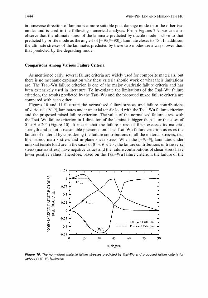
Figures 10 and 11 illustrate the normalized failure stresses and failure contributionsof various ½þ=–s laminates under uniaxial tensile load with the Tsai–Wu failure criterionand the proposed mixed failure criterion. The value of the normalized failure stress withthe Tsai–Wu failure criterion in 1-direction of the lamina is bigger than 1 for the cases of08 < < 208 (Figure 10). It means that the failure stress of fiber excesses its materialstrength and is not a reasonable phenomenon. The Tsai–Wu failure criterion assesses thefailure of material by considering the failure contributions of all the material stresses, i.e.,fiber stress, matrix stress and in-plane shear stress. When the ½þ=–s laminates underuniaxial tensile load are in the cases of 08 < < 208, the failure contributions of transversestress (matrix stress) have negative values and the failure contributions of shear stress havelower positive values. Therefore, based on the Tsai–Wu failure criterion, the failure of the
Figure 10. The normalized material failure stresses predicted by Tsai–Wu and proposed failure criteria forvarious [þ/�]s laminates.
1444 WEN-PIN LIN AND HSUAN-TEH HU

laminate must occur at a high value of failure contribution in fiber stress to make the sumof various failure contributions equal to unity. In these cases, the failure contribution offiber stress usually excesses the value 1 and it results in an overestimated failure stresses infiber direction. To eliminate this unreasonable estimation, an extra limitation should beadded into the Tsai–Wu failure criterion to obtain a more accurate and reasonableprediction. The proposed limitation in this study is �1=Xut � 1 (as �1 > 0) or �1=Xuc � 1(as �1 < 0). The combination of Tsai–Wu failure criterion with the proposed limitation iscalled the mixed failure criterion. The results predicted by mixed failure criterion inFigures 10 and 11 shows the reasonable values. In addition, Figure 11 indicates that thefailure of laminate is induced by the fiber stress, matrix stress, in-plane shear stress, or anycombination of these stresses for various ½þ=� s laminates under uniaxial tensile load.When 08 � � 258, the failure of laminate is mainly induced by fiber stress. For258 < < 358, the failure of laminate is induced by the combination of fiber stress andin-plane shear stress. In the cases of 358 � � 458, the failure of laminate is primarilyinduced by in-plane shear stress. When 458 < < 508, the failure of laminate is induced bythe combination of in-plane shear stress and matrix stress. For 508 � � 908, the failureof laminate is almost induced by matrix stress. It should be noted that the fiber stress andin-plane shear stress have the same normalized stress and failure contribution as failureoccurring about at ¼ 308.
Figure 12 illustrates the comparison of uniaxial tensile stress–strain curves betweenvarious failure criteria with experimental data [2] for ½þ30=�30s composite laminate. Theresults predicted by the Tsai–Wu and the proposed mixed failure criteria have thebest agreement with the experimental data, and the result predicted by the Chang failurecriterion has a better agreement with the experimental data than the maximum stresscriterion does. As discussed preciously, the failure of [þ /�]s laminate is mainly inducedby the combination of fiber stress and in-plane shear stress when 25� < <35�. Thus, forthe [þ 30/�30]s laminate, the fiber stress and in-plane shear stress play the same importantroles in determining the on set of failure. The maximum stress theory does not consider
Figure 11. The failure contributions of material stresses predicted by Tsai–Wu and proposed failure criteria forvarious [þ/�]s laminates.
Nonlinear Analysis of Fiber-Reinforced Composite Laminates 1445

the coupling failure contribution of fiber stress and in-plane shear stress in the failureprocess. Hence, the failure stress of laminate in this case will be greatly overestimated dueto only considering the failure of fiber stress or in-plane shear stress.
Figure 13 indicates the comparison of failure stresses for various ½þ=�s laminatessubjected to uniaxial tensile load with various failure criteria against experimental data [2].In the cases of 0� � � 25�, the failure stresses predicted by maximum stress criterion,
Figure 12. Uniaxial tensile stress–strain curve simulated by various failure criteria for [þ30/�30]s laminate.
Figure 13. Uniaxial tensile failure stress predicted by various failure criteria for various [þ/�]s laminates.
1446 WEN-PIN LIN AND HSUAN-TEH HU
Chang failure criterion and the proposed mixed failure criterion are similar. But the failurestresses predicted by Tsai–Wu failure criterion are overestimated, especially at ¼ 15�.This is because that higher failure contributions of fiber stresses are needed to balance thenegative failure contributions induced by matrix stresses. In the cases of 25�<<35�, thefailure stresses predicted by Tsai–Wu and proposed mixed failure criteria are similarbecause of using the same post-damage mode. The results predicted by maximum stresscriterion and Chang failure criterion are overestimated. This is because that the maximumstress criterion does not consider the failure contributions coupled between fiber stressand in-plane shear stress. For Chang failure criterion, it is due to the use of the constantstiffness instead of degrading stiffness for matrix in the post-damage process. In the casesof 35�<<90�, the results predicted by various failure criteria are very similar.
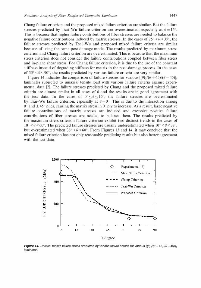
Figure 14 indicates the comparison of failure stresses for various [()3/(þ 45)/(� 45)]slaminates subjected to uniaxial tensile load with various failure criteria against experi-mental data [2]. The failure stresses predicted by Chang and the proposed mixed failurecriteria are almost similar in all cases of and the results are in good agreement withthe test data. In the cases of 0� � � 15�, the failure stresses are overestimatedby Tsai–Wu failure criterion, especially at ¼ 0�. This is due to the interaction among0� and � 45� plies, causing the matrix stress in 0� ply to increase. As a result, large negativefailure contributions of matrix stresses are induced and excessive positive failurecontributions of fiber stresses are needed to balance them. The results predicted bythe maximum stress criterion failure criterion exhibit two distinct trends in the cases of10�<<60�. The predicted failure stresses are usually underestimated when 10�<<38�,but overestimated when 38�<<60�. From Figures 13 and 14, it may conclude that themixed failure criterion has not only reasonable predicting results but also better agreementwith the test data.
Figure 14. Uniaxial tensile failure stress predicted by various failure criteria for various [()3/(þ45)/(� 45)]s
laminates.
Nonlinear Analysis of Fiber-Reinforced Composite Laminates 1447

Comparisons Between Elastic–Plastic and Proposed Nonlinear Constitutive Models
Figures 15 and 16 illustrate the comparison of uniaxial tensile stress–strain curve for½ð0Þ3=þ45=�45s and ½ð65Þ3=þ20=�70s laminates with Vaziri’s elastic–plastic constitutivemodel [5] and the present model against the test data [2]. The mechanical responses of
Figure 15. Uniaxial tensile stress–strain curve simulated by Vaziri model and present model for[(0)3/þ45/�45]s laminate.
Figure 16. Uniaxial tensile stress–strain curve simulated by Vaziri model and present model for[(65)3/þ20/�70]s laminate.
1448 WEN-PIN LIN AND HSUAN-TEH HU

these two types of laminates exhibit the interaction of normal stress and in-plane shearstress with neighboring laminae, especially for the [(65)3/þ20/�70]s laminate. The resultssimulated by the present model have better agreements with the test data than the Vaziri’smodel does. The results simulated by the Vaziri’s model have fair agreements with the testdata of ½ð0Þ3=þ45=�45s, laminate. However, due to the poor simulation on in-plane shearstress of the lamina, the results simulated by the Vaziri’s model give very poor agree-ments with the test data of [(65)3/þ 20/�70]s laminate. Thus, the present model is really areasonable and accurate analysis model in predicting the stress–strain behavior as well asthe ultimate stress of Boron/Epoxy composite laminates for various symmetrical stakingsequences under uniaxial tensile load.
CONCLUSIONS
This paper presents a material constitutive model for simulating the mechanicalresponse and predicting the ultimate strength of various symmetrical composite laminatessubjected to uniaxial tensile load. The model is composed of three parts: (1) nonlinearconstitutive model, (2) mixed failure criterion, and (3) post-damage mode. In the nonlinearconstitutive model, the fiber and matrix are simulated by elastic–plastic behavior and thein-plane shear is simulated by nonlinear behavior with variable shear parameter, which is afunction of in-plane shear strain. The mixed failure criterion is composed of the Tsai–Wufailure criterion and the maximum stress criterion to determine the damage onset of alamina. The present failure criterion can eliminate the over estimation in fiber stresses asthe negative failure contributions of matrix stresses occurring in the lamina. In the post-damage process, the fiber and the in-plane shear are simulated by a brittle mode and thematrix by a degrading mode.
The ultimate strengths predicted by the various failure criteria together with variouspost-damage modes against the experimental data show that the proposed mixed failurecriterion and post-damage modes could predict the failure response of compositelaminates under uniaxial tension more accurately than others. The numerical resultssimulated by Vaziri’s elastic–plastic constitutive model and the present constitutive modelagainst the test data illustrate that the present constitutive model can predict the stress–strain relation, especially for the interaction of normal stress and in-plane shear stress inneighboring laminae, more accurately. The favorable agreement between the presentnumerical predictions and experimental data demonstrates that the nonlinear constitutivemodel together with the mixed failure criterion and degrading post-damage modes is auseful tool in the nonlinear failure analysis of fiber-reinforced composite laminatedmaterials. It shows the potential of the present nonlinear failure approach.
REFERENCES
1. Hahn, H.T. (1973). Nonlinear behavior of laminated composites. Journal of Composite Materials,7: 257–271.
2. Petit, P.H. and Waddoups, M.E. (1969). A method of predicting the nonlinear behavior oflaminated composites. Journal of Composite Materials, 3: 2–19.
3. Hahn, H.T. and Tsai, S.W. (1973). Nonlinear elastic behavior of unidirectional compositelaminates. Journal of Composite Materials, 7: 102–118.
Nonlinear Analysis of Fiber-Reinforced Composite Laminates 1449
4. Sun, C.T. and Chen, J.L. (1989). A simple flow rule for characterizing nonlinear behavior offiber composite. Journal of Composite Materials, 23: 1009–1020.
5. Vaziri, R., Olson, M.D. and Anderson, D.L. (1991). A plasticity-based constitutive model forfibre-reinforced composite laminates. Journal of Composite Materials, 25: 512–535.
6. Nanda, A. and Kuppusamy, T. (1991). Three-dimensional elastic-plastic analysis of laminatedcomposite plates. Composite Structures, 17: 213–225.
7. Griffin, O.H., Kamat, M.P. and Herakovich, C.T. (1981). Three-dimensional inelastic finiteelement analysis of laminated composites. Journal of Composite Materials, 15: 543–560.
8. Kenaga, D., Doyle, J.F. and Sun, C.T. (1987). The characterization of boron/aluminumcomposite in the nonlinear range as an orthotropic elastic-plastic material. Journal of CompositeMaterials, 21: 516–531.
9. Allen, H., Harris, C.E. and Groves, S.E. (1987). A thermomechanical constitutive theory forelastic composites with distributed damage-I. Theoretical development. Int. J. Solids Structures,23: 1301–1318.
10. Rowlands, R.E. (1985). Strength (failure) theories and their experimental correlation. In:Sih, G.C. and Skudra, A.M. (eds.), Failure Mechanics of Composites. Amsterdam: Elsevier.pp. 71–125.
11. Tsai, S.W. and Wu, E.M. (1971). A general theory of strength for anisotropic materials. Journalof Composite Materials, 5: 58–80.
12. Hoffman, O. (1967). The brittle strength of orthotropic materials. Journal of CompositeMaterials, 1: 200–206.
13. Azzi, V.D. and Tsai, S.W. (1965). Anisotropic strength of composite. Exp. Mech., 5: 283–288.
14. Hashin, Z. (1980). Failure criteria for unidirectional fiber composites. J. Appl. Mech., 47:329–334.
15. Lee, J.D. (1982). Three dimensional finite element analysis of damage accumulation incomposite laminate. Computers and Structures, 15: 335–350.
16. Chang, F.K. and Lessard, L.B. (1991). Damage tolerance of laminated composite containing anopen hole and subjected to compressive loadings: part I – analysis. Journal of CompositeMaterials, 25: 2–43.
17. Mindlin, R.D. (1951). Influence of rotator inertia and shear flexural motions of isotropic elasticplate. J. Appl. Mech., 18: 31–38.
18. Zhu, H. and Sankar, B.V. (1998). Evaluation of failure criteria for fiber composites using finiteelement micromechanics. Journal of Composite Materials, 32: 766–782.
19. Narayanaswami, R. and Adelman, H.M. (1977). Evaluation of the tensor polynomial andHoffman strength theories for composite materials. Journal of Composite Materials, 11: 366–377.
20. Hu, H.-T. (1993). Influence of in-plane shear nonlinearity on buckling and postbucklingresponses of composite laminate plates and shells. Journal of Composite Materials, 27: 138–151.
21. Hibbitt, Karlsson & Sorensen, Inc. (2000). ABAQUS Theory Manual and User Manual. Version5.8, Providence, Rhode Island.
22. Lin, W.-P. and Hu, H.-T. (2000). A method of predicting the nonlinear and plastic behavior offiber-reinforced composite laminates. In: Proceedings of the Second Asia-Australasian Conferenceon Composite Materials. Kyongju, Korea, August 18–20. pp. 901–907.
1450 WEN-PIN LIN AND HSUAN-TEH HU