nonlinear dynamic analysis of a concrete gravity dam...
TRANSCRIPT
Scientia Iranica A (2013) 20(6), 1676{1684
Sharif University of TechnologyScientia Iranica
Transactions A: Civil Engineeringwww.scientiairanica.com
Nonlinear dynamic analysis of a concrete gravity damconsidering an elastoplastic constitutive model for thefoundation
S.M. Aghajanzadeh and M. Ghaemian�
Department of Civil Engineering, Sharif University of Technology, Tehran, P.O. Box 11155-9313, Iran.
Received 18 February 2013; received in revised form 28 April 2013; accepted 21 May 2013
KEYWORDSFoundation'selastoplastic behavior;Nonlinear dynamicanalysis;Mohr-Coulomb model;Smeared crack model;Seismic analysis;Concrete gravity dam.
Abstract. Dam failure can result in a catastrophic break followed by a ood wave, oftenwith considerable loss of life or property. One of the main causes of dam failure is loss ofshear strength and the existence of discontinuity within the foundation. Dynamic analysisof concrete dams usually considered concrete behavior to be nonlinear and the foundationrock is assumed to be linear. In this study, seismic analysis of a concrete gravity damwas conducted to investigate the e�ect of the foundation on the nonlinear response. A�nite element model of a dam-reservoir-foundation was considered to properly model thefoundation as well as dam body nonlinear behaviors. An elasto-plastic formulation was usedto model the foundation. The Mohr-Coulomb model was utilized for the yield and potentialfunctions of the foundation. The dam body was modeled using a smeared crack model.After modeling the dam-reservoir foundation, the horizontal recorded ground accelerationof the Kobe 1995 earthquake was applied to the model and results were studied. It wasfound that cracks form at the crest and hill of the dam. Using the elastoplastic modelfor the foundation is more realistic, and under di�erent boundary conditions, a signi�cantamount of energy will be dissipated in the foundation.c 2013 Sharif University of Technology. All rights reserved.
1. Introduction
Concrete dams are an important part of nation'sinfrastructure. They store water for di�erent purposes,such as irrigation, water supply, ood control, electricpower, recreation and the improvement of navigation.The safety of concrete dams is a major challengefor owners due to its possible failure consequenceswhen subjected to severe earthquake ground motion.Therefore, it is required to determine the concrete grav-ity dam's response under di�erent earthquake groundmotion in high seismic zones. Rescher (1990) indi-cated that most concrete gravity dams will experience
*. Corresponding author. Tel.: +98 21 66164242;Fax: +98 21 66014828E-mail address: [email protected] (M. Ghaemian)
cracking even under operational loading condition [1].Therefore, the assumption of linear behavior may notbe appropriate in the analysis of the seismic response ofconcrete gravity dams, and nonlinear dynamic analysisneeds to be carried out for dam-reservoir-foundationsystems. The nonlinear dynamic response of concretedams depends on their interaction with the reservoirand foundation, and the approach to modeling theseinteractions depends on the constitutive models con-sidered for their materials.
Dam-foundation interaction has been the topicof many studies. Motamedi et al. (2008) studiedthe e�ect of the foundation on the seismic behaviorof concrete dams. They concluded that consideringa rigid foundation a�ects the behavior of a concretedam, and the model with a massless foundation is veryconservative. Their dynamic �nite element analysis

S.M. Aghajanzadeh and M. Ghaemian/Scientia Iranica, Transactions A: Civil Engineering 20 (2013) 1676{1684 1677
resulted that incorporating the dam-foundation rockinteraction is dependent on the dam and foundationmodulus used in the analysis [2]. Sarkar et al. (2007)studied the e�ect of the foundation on the nonlinearbehavior of concrete dams. Accordingly, they foundthat the results of their analysis related to foundationand reservoir interaction. They concluded that by re-ducing foundation modules, deformation increases [3].Arabshahi and Lot� (2008) investigated the earthquakeresponse of concrete gravity dams, including dam-foundation interface nonlinearities. Their results showthat sliding generally reduces the maximum amountof tensile principal stresses in the dam body, althoughthere are some cracks in the body of the dam [4]. Fish-man (2008) studied the shear failure of brittle materialsand concrete structures on the rock foundation. It wasconcluded that the failure of brittle materials by sheartakes place, along with weak surfaces, characterizedby both low values of shear strength (? and C) andlow levels of normal stresses. Using this model, thecause of the serious Malpasset dam failure in Francewas investigated, too [5].
In this study, the dynamic nonlinear analysis ofa dam-reservoir-foundation is carried out to obtain thedam response, considering foundation nonlinearity aswell as dam body nonlinearity. The main purpose ofthis study is to predict the behavior of concrete gravitydams under seismic loads, considering an elastoplasticmodel of the foundation.
2. Coupled equation of dam-reservoir-foundation
The coupled dam-reservoir equations are representedas follows:
[M ]f�ug+ [C]f _ug+ [K]fug = ff1g � [M ]f�ugg+ [Q]fpg = fF1g+ [Q]fpg; (1)
[G]f�pg+ [C 0]f _pg+ [K 0]fpg = ff2g� �[Q]T (f�ug+ f�ugg) = fF2g � �[Q]T f�ug; (2)
where [M ], [C] and [K] are mass, damping and sti�nessmatrices of the structure, including the body of thedam and foundation, and [G], [C 0] and [K 0] are matricesrepresenting the mass, damping and sti�ness of thereservoir, respectively. [Q] is the coupling matrix;ff1g is the vector of the body force and hydrodynamicforce; fF2g is the component of the force due toacceleration at the boundaries of the dam-reservoirand reservoir-foundation; and fpg and fug are thevector of hydrodynamic pressures and displacements.f�ugg are the ground acceleration and � is the densityof the uid. The dot represents the time derivative.
For solving dam-reservoir-foundation interaction, thestaggered displacement solution scheme was used [6].
3. Material behavior
A dam body and foundation are assumed to behaveelastically at the start of the analysis. No linearconstitutive models are used for the dam body andfoundation when they go beyond the elastic region. Acomputer code was developed in this study for consid-ering a dynamic constitutive model for the foundationand concrete.
3.1. Concrete and foundation in elastic regionHook's law is used for determining the response of thestructure in the elastic region as below:
f�g = [D]f"g; (3)
where [D] is the module matrix, f�g is the stress vectorand f"g is the strain vector.
The concrete gravity dam's monoliths, usuallyunkeyed or lightly grouted, are expected to vibrateindependently under severe ground excitations. So,two-dimensional plane stress idealization seems to beappropriate for the nonlinear seismic response study ofconcrete gravity dams. By assuming two-dimensionalplane stress idealization, [D] could be written as:
[D] =E
1� �2
241 � 0� 1 00 0 1��
2
35 : (4)
3.2. Crack initiation and propagation criteriaof concrete
The compressive stresses in concrete gravity dams areexpected to be low, even under severe ground exci-tations, so, linear elastic behavior is assumed for theconcrete of gravity dams under compressive loading.In contrast, the initiation of new cracks is assumed inconcrete gravity dams when the principal tensile stressreaches the tensile strength of concrete. Tensile energydensity was used as criteria for crack initiation andpropagation in an element. An element will crack ifthe tensile energy density, �1"1
2 , reaches the U0 valueas follows:
12�1"1 = U0 =
�2i
2E; (�1 > 0); (5)
where �1 and "1 are the major principal stress andstrain, respectively, and �i is the apparent tensilestrength of concrete [7].
3.3. Constitutive relationship during softeningfor concrete
A linear softening branch of concrete is assumed andthe principle of conservation of energy should beconserved. By considering these two important factors,
1678 S.M. Aghajanzadeh and M. Ghaemian/Scientia Iranica, Transactions A: Civil Engineering 20 (2013) 1676{1684
the slope of softening branches of concrete determined,such as the energy released per area, will remainconstant. At last, in �nite element analysis, the �nalstrains of no tensile resistance are de�ned as:
"f =2Gf�0lc
; "0f =2G0f�00lc
; (6)
where "f , Gf , �0 and lc are �nal strains, fractureenergy, tensile strength of concrete and characteristiclength of element, respectively [7]. Parameters withprime notation indicate corresponding values for dy-namic analysis.
For formulating the softening behavior of con-crete, a tangent modulus sti�ness technique was used.In this method, the sti�ness matrix was obtainedby an incremental stress-strain relationship, and theconstitutive matrix, relating the local stresses to localstrains, is de�ned as [7]:
[D]np =E
1� ��2
24 � �� 0�� 1 00 0 � 1���
2(1+�)
35 � =EnE; (7)
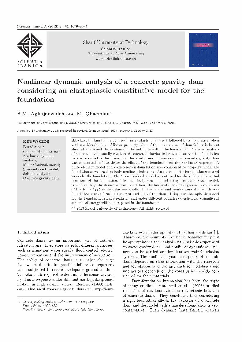
where parameter � is the ratio between the softeningYoung's modulus, En, in the direction normal to afracture plane, E is the initial isotropic elastic modulus,and � is the shear resistance factor. These parametersare shown in Figure 1.
A coaxial rotating crack model is considered,with respect to the orientation of crack bands, in�nite element analysis. Thus, strains "n and "p are,respectively, "1, and "2, at the newly oriented materialreference state. Using an implicit de�nition of thesoftened shear modulus in cracked elements, parameter� is de�ned as follow:
� =1 + �
1� ��2
��"n � "p"n � "p � ��
�0 � � � 1: (8)
Here, "n and "p are the normal strain components inthe directions normal and parallel to the fracture plane,respectively.
The local constitutive relationship matrix, [Dnp],
Figure 1. Stress-strain relationship for concrete.
can be transformed to the global coordinate directionsas follows:
[Dxy] = [T ]T [D]np[T ]; (9)
where [T ] is the strain transformation matrix, de�nedas follows, in terms of the inclination of the normal toits crack plane (�).
[T ]=
24 cos2 � sin2 � sin � cos �sin2 � cos2 � � sin � cos �
�2 sin � cos � 2 sin � cos � cos2 ��sin2 �
35 :(10)
3.4. Constitutive model for foundationThe elastic behavior of the foundation is discussed inthe previous section. For higher levels of loading, whenstresses in the foundation are beyond the elastic limit,a plasticity theory was used for modeling the behaviorof the foundation.
3.4.1. Elasto-plastic behavior considered for rockmasses
The elastoplastic constitutive relation of incrementalstress-strain in the foundation in the plastic region isconsidered as [8]:
d�ij =
Dijkl � Dijmn
@F@�mn
@Q@�rsDrskl
@F@�mnDmnrs
@Q@�rs +m @Q
@�rs�rs
!d"kl
= Depijkld"kl; (11)
which denotes the yielding function as F (�ij ;m) andthe plastic potential function as Q(�ij), respectively,where m is a scalar function representing work-hardening or work softening.
4. Foundation modeling for dynamic analysis
The Mohr-Coulomb criterion is used as the yieldfunction and the plastic potential function [8]. Yieldfunction and plastic potential function are assumed tobe the same. With this assumption, the sti�ness matrixis symmetric and calculation is much easier. Thefoundation behavior in the plastic region is assumedto have no hardening or softening.
4.1. Sti�ness matrix used for modeling thefoundation
Because of the two dimensional analyses assumption,the sti�ness matrix in the two dimensional coordinateis obtained as [8]:8<:d�xxd�yy
d�xy
9=; =
24Dep11 Dep
12 Dep13
Dep21 Dep
22 Dep23
Dep31 Dep
32 Dep33
358<:d"xxd"yyd"xy
9=; ; (12)
Depij = Dij � 1
H
3Xk=1
fkDik
! 3Xk=1
qkDkj
!; (13)
S.M. Aghajanzadeh and M. Ghaemian/Scientia Iranica, Transactions A: Civil Engineering 20 (2013) 1676{1684 1679
where:
[D]=E
1� �2
241 � 0� 1 00 0 1��
2
35=
24D11 D12 D13D21 D22 D23D31 D32 D33
35 ;(14)
and:
H =3Xk=1
"qk
3Xl=1
flDlk
#+m(q1�xx+q2�yy + q3�xy);
(15)
fk =@F@�k
; (16)
qk =@Q@�k
: (17)
In this study, there is no hardening or softening for thefoundation behavior, so, m = 0. The Mohr-Coulombcriterion is used for the yield and plastic potentialfunction, as:
� = C � �n tan?: (18)
In the above equation, � is the critical shear stress, �nis the normal stress acting over the failure plane, ? isthe angle of internal friction and C is the inherent shearstrength or cohesion of the material. Writing the Mohr-Coulomb criterion according to principal stresses, then,equations for yielding function and plastic potentialfunction become:
F =Q=1+sin�1�sin�
�(�max)��min� 2�C �cos�1�sin�
; (19)
�max =�x + �y
2+
s��x � �y
2
�2
+ �xy2; (20)
�min =�x + �y
2�s�
�x � �y2
�2
+ �xy2: (21)
fk and qk could be calculated as below:
f1 = q1 =@F@�x
=sin�
2�
�x��y4r�
�x��y2
�2+ �xy2
; (22)
f2 = q2 =@F@�y
=sin�
2+
�x��y4r�
�x��y2
�2+ �xy2
; (23)
f3 = q3 =@F@�xy
= � �xyr��x��y
2
�2+ �xy2
: (24)
5. Foundation boundary conditions
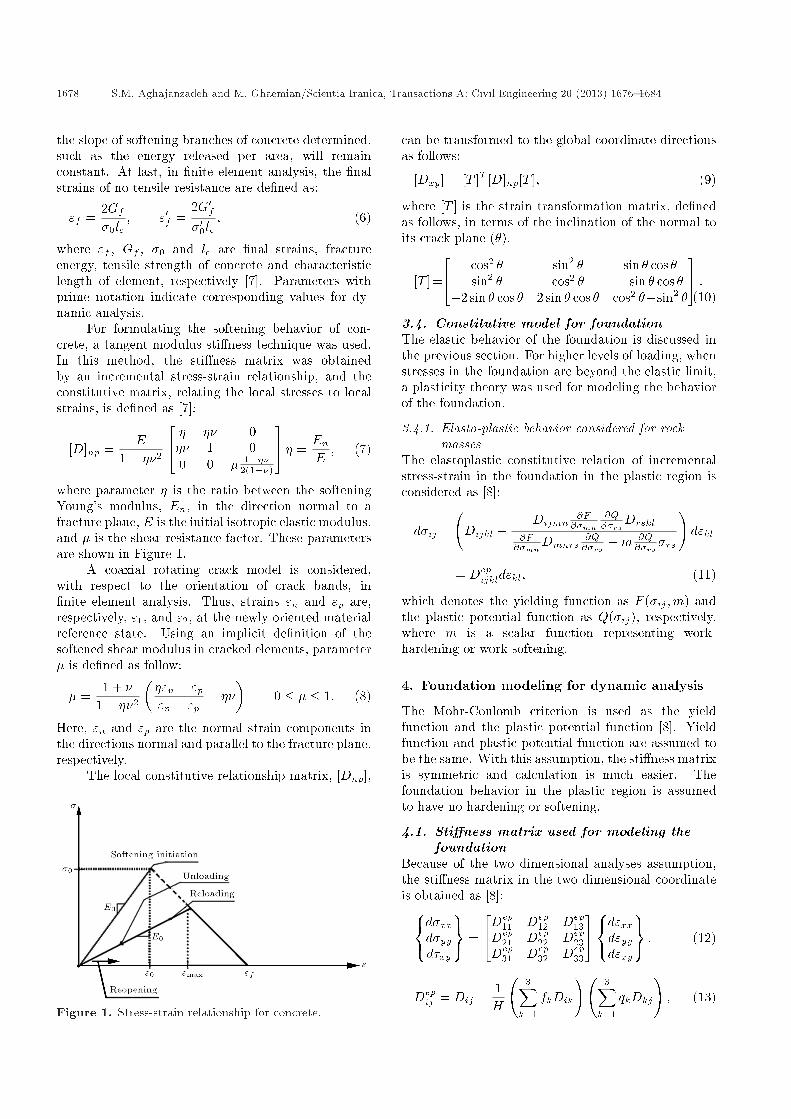
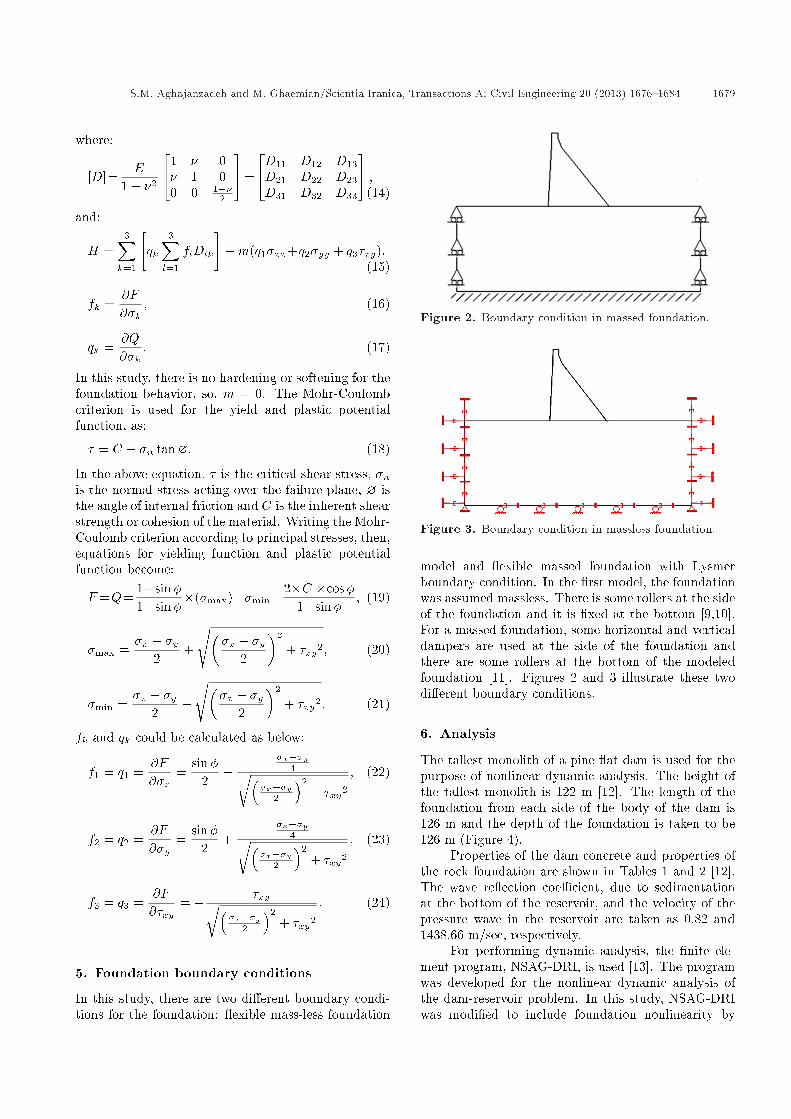
In this study, there are two di�erent boundary condi-tions for the foundation: exible mass-less foundation
Figure 2. Boundary condition in massed foundation.
Figure 3. Boundary condition in massless foundation.
model and exible massed foundation with Lysmerboundary condition. In the �rst model, the foundationwas assumed massless. There is some rollers at the sideof the foundation and it is �xed at the bottom [9,10].For a massed foundation, some horizontal and verticaldampers are used at the side of the foundation andthere are some rollers at the bottom of the modeledfoundation [11]. Figures 2 and 3 illustrate these twodi�erent boundary conditions.
6. Analysis
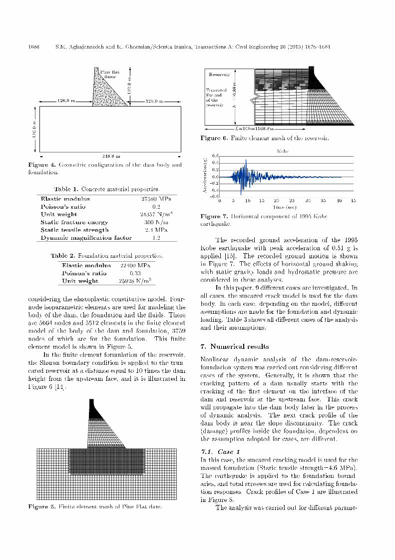
The tallest monolith of a pine at dam is used for thepurpose of nonlinear dynamic analysis. The height ofthe tallest monolith is 122 m [12]. The length of thefoundation from each side of the body of the dam is126 m and the depth of the foundation is taken to be126 m (Figure 4).
Properties of the dam concrete and properties ofthe rock foundation are shown in Tables 1 and 2 [12].The wave re ection coe�cient, due to sedimentationat the bottom of the reservoir, and the velocity of thepressure wave in the reservoir are taken as 0.82 and1438.66 m/sec, respectively.
For performing dynamic analysis, the �nite ele-ment program, NSAG-DRI, is used [13]. The programwas developed for the nonlinear dynamic analysis ofthe dam-reservoir problem. In this study, NSAG-DRIwas modi�ed to include foundation nonlinearity by
1680 S.M. Aghajanzadeh and M. Ghaemian/Scientia Iranica, Transactions A: Civil Engineering 20 (2013) 1676{1684
Figure 4. Geometric con�guration of the dam body andfoundation.
Table 1. Concrete material properties.
Elastic modulus 27580 MPaPoisson's ratio 0.2Unit weight 24357 N/m3
Static fracture energy 300 N/mStatic tensile strength 2.4 MPaDynamic magni�cation factor 1.2
Table 2. Foundation material properties.
Elastic modulus 22400 MPaPoisson's ratio 0.33Unit weight 25928 N/m3
considering the elastoplastic constitutive model. Four-node isoparametric elements are used for modeling thebody of the dam, the foundation and the uids. Thereare 5664 nodes and 5512 elements in the �nite elementmodel of the body of the dam and foundation, 3759nodes of which are for the foundation. This �niteelement model is shown in Figure 5.
In the �nite element formulation of the reservoir,the Sharan boundary condition is applied to the trun-cated reservoir at a distance equal to 10 times the damheight from the upstream face, and it is illustrated inFigure 6 [14].
Figure 5. Finite element mesh of Pine Flat dam.
Figure 6. Finite element mesh of the reservoir.
Figure 7. Horizontal component of 1995 Kobeearthquake.
The recorded ground acceleration of the 1995Kobe earthquake with peak acceleration of 0.51 g isapplied [15]. The recorded ground motion is shownin Figure 7. The e�ects of horizontal ground shakingwith static gravity loads and hydrostatic pressure areconsidered in these analyses.
In this paper, 9 di�erent cases are investigated. Inall cases, the smeared crack model is used for the dambody. In each case, depending on the model, di�erentassumptions are made for the foundation and dynamicloading. Table 3 shows all di�erent cases of the analysisand their assumptions.
7. Numerical results
Nonlinear dynamic analysis of the dam-reservoir-foundation system was carried out considering di�erentcases of the system. Generally, it is shown that thecracking pattern of a dam usually starts with thecracking of the �rst element on the interface of thedam and reservoir at the upstream face. This crackwill propagate into the dam body later in the processof dynamic analysis. The next crack pro�le of thedam body is near the slope discontinuity. The crack(damage) pro�les inside the foundation, dependent onthe assumption adopted for cases, are di�erent.
7.1. Case 1In this case, the smeared cracking model is used for themassed foundation (Static tensile strength=4.6 MPa).The earthquake is applied to the foundation bound-aries, and total stresses are used for calculating founda-tion responses. Crack pro�les of Case 1 are illustratedin Figure 8.
The analysis was carried out for di�erent parame-

S.M. Aghajanzadeh and M. Ghaemian/Scientia Iranica, Transactions A: Civil Engineering 20 (2013) 1676{1684 1681
Table 3. Di�erent cases for foundation in the analysis.
Case 1 Smeared model(foundation)
Massed foundation Total stress Static tensilestrenght=4.6 MPa
Earthquake at thefoundation boundaries
Case 2 Elastoplastic model(foundation)
Massed foundation Total stress ? = 47 deg, C = 0:6 MPa Earthquake atfoundation boundaries
Case 3 Elastoplastic model(foundation)
Massed foundation E�ective stress ? = 47 deg, C = 0:6 MPa Earthquake atfoundation boundaries
Case 4 Elastoplastic model(foundation)
Massed foundation Total stress ? = 47 deg, C = 0:6 MPa Earthquake at damfoundation interface
Case 5 Elastoplastic model(foundation)
Massed foundation E�ective stress ? = 47 deg, C = 0:6 MPa Earthquake at damfoundation interface
Case 6 Elastoplastic model(foundation)
Massless foundation Total stress ? = 47 deg, C = 0:6 MPa Earthquake atfoundation boundaries
Case 7 Elastoplastic model(foundation)
Massless foundation E�ective stress ? = 47 deg, C = 0:6 MPa Earthquake atfoundation boundaries
Case 8 Elastoplastic model(foundation)
Massless foundation Total stress ? = 47 deg, C = 0:6 MPa Earthquake at damfoundation interface
Case 9 Elastoplastic model(foundation)
Massless foundation E�ective stress ? = 47 deg; C = 0:6 MPa Earthquake at damfoundation interface
Figure 8. Crack pro�les of Case 1 (smeared model;massed foundation; total stresses; static tensilestrength=4.6 MPa; earthquake at foundation boundaries).
ters of foundation nonlinearity, considering the smearedcrack model. Based on the crack pro�le from all analy-ses, it was found that the smeared crack model for thefoundation is not appropriate, knowing that the failuremode in the foundation is the shear failure mode.
The crack patterns for all analyses are more orless the same as Case 1 for the foundation. Generally,foundation cracking starts at the upstream and propa-gates vertically into the foundation for a wide range ofparameters of the model.
7.2. Case 2The elastoplastic model is used for the massed founda-tion, and the earthquake is applied to the foundationboundaries. Total stresses are used for calculatingfoundation responses, and friction angle and cohesionare taken as 47 degree and 0.6 MPa, respectively. Crackpro�les of Case 2 are illustrated in Figure 9. Whenthe elastoplastic model is used for the foundation, theintensity of damage to the body of the dam is lower incomparison to the condition when the smeared modelis used. The analysis was stopped earlier in Case 1compared to Case 2 because of the high intensity ofoccurred damage.
Figure 9. Crack pro�les of Case 2 (elastoplastic model;massed foundation; total stress; ? = 47 deg;C = 0:6 MPa; earthquake at foundation boundaries).
This fact can be interpreted by the energy thatdissipated in each case. Considering the smeared modelfor the foundation, the amount of energy dissipated ineach cycle of loading in the foundation is less than thecase of the elastoplastic model for the foundation.
7.3. Case 3In this case, the elastoplastic model is used for themassed foundation, and the earthquake is appliedto the foundation boundaries. E�ective stresses areused for calculating foundation responses, and thefriction angle and cohesion are 47 degree and 0.6 MPa,respectively. Crack pro�les of Case 3 are illustrated inFigure 10.
Results show that employing e�ective stressesinstead of total stresses gives a more realistic response.Using e�ective stresses in the analysis, there are moreelements of the foundation in the plastic region.
7.4. Case 4In this case, the elastoplastic model is used for themassed foundation, and the earthquake is insertedinto the dam foundation interface. Total stresses areused for calculating foundation responses, and thefriction angle and cohesion are 47 degree and 0.6 MPa,

1682 S.M. Aghajanzadeh and M. Ghaemian/Scientia Iranica, Transactions A: Civil Engineering 20 (2013) 1676{1684
Figure 10. Crack pro�les of Case 3 (elastoplastic model;massed foundation; e�ective stress; ? = 47 deg;C = 0:6 MPa; earthquake at foundation boundaries).
Figure 11. Crack pro�les of Case 4 (elastoplastic model;massed foundation; total stress; ? = 47 deg;C = 0:6 MPa; earthquake at dam foundation interface).
Figure 12. Crack pro�les of Case 5 (elastoplastic model;massed foundation; e�ective stress; ? = 47 deg;C = 0:6 MPa; earthquake at dam foundation interface).
respectively. Crack pro�les of Case 4 are illustrated inFigure 11.
7.5. Case 5In this case, the elastoplastic model is used for themassed foundation, and the earthquake is insertedinto the dam foundation interface. E�ective stressesare used for calculating foundation responses, and thefriction angle and cohesion are 47 degree and 0.6 MPa,respectively. Crack pro�les of Case 5 are illustrated inFigure 12.
When the earthquake is inserted into the massedfoundation boundaries instead of the dam-massed foun-dation interface, the intensity of damage to the bodyof the dam is lower. The analysis stopped earlierin Case 5 compared to Case 3 because of the highintensity of occurred damage in the body of the dam,but at the end of the analysis, there were fewerelements in the plastic region for the case in whichthe earthquake was applied to the dam-foundationinterface.
When the earthquake is inserted into the massedfoundation boundaries, there are more e�ects of energyabsorption in the foundation of the elements. There-fore, the number of plastic elements of the foundationwill increase and the foundation absorbs more energyinto plastic region. So, it will reduce the amount
Figure 13. Crack pro�les of Case 6 (elastoplastic model;massless foundation; total stress; ? = 47 deg;C = 0:6 MPa; earthquake at foundation boundaries).
Figure 14. Crack pro�les of Case 7 (elastoplastic model;massless foundation; e�ective stress; ? = 47 deg;C = 0:6 MPa; earthquake at foundation boundaries).
of damage to the dam body, but there are moreplastic elements in the foundation at the end of theanalysis.
7.6. Case 6In this case, the elastoplastic model is used for themassless foundation, and the earthquake is insertedinto the foundation boundaries. Total stresses areused for calculating foundation responses, and thefriction angle and cohesion are 47 degree and 0.6 MPa,respectively. Crack pro�les of Case 6 are illustrated inFigure 13.
7.7. Case 7In this case, the elastoplastic model is used for themassless foundation, and the earthquake is insertedinto the foundation boundaries. E�ective stresses areused for calculating foundation responses, and thefriction angle and cohesion are 47 degree and 0.6 MPa,respectively. Crack pro�les of Case 7 are illustrated inFigure 14. Using a massed foundation and consideringits inertia and energy absorption, the intensity ofdamage to the dam body reduces.
7.8. Case 8The elastoplastic model is used for the massless foun-dation, and the earthquake is inserted into the damfoundation interface. Total stresses are used andfriction angle and cohesion are 47 degree and 0.6 MPa,respectively. Crack pro�les of Case 8 are illustrated inFigure 15.
7.9. Case 9The elastoplastic model is used for the massless foun-dation, and the earthquake is inserted in the damfoundation interface. E�ective stresses are used andfriction angle and cohesion are 47 degree and 0.6 MPa,

S.M. Aghajanzadeh and M. Ghaemian/Scientia Iranica, Transactions A: Civil Engineering 20 (2013) 1676{1684 1683
Figure 15. Crack pro�les of Case 8 (elastoplastic model;massless foundation; total stress; ? = 47 deg;C = 0:6 MPa; earthquake at dam foundation interface).
Figure 16. Crack pro�les of Case 9 (elastoplastic model;massless foundation; e�ective stress; ? = 47 deg;C = 0:6 MPa; earthquake at dam foundation interface).
respectively. Crack pro�les of Case 9 are illustrated inFigure 16.
As shown in the massless foundation, there is noremarkable di�erence between inserting the earthquakein the dam-foundation interface or at the foundationboundaries. For a massless foundation, the velocity ofwave propagation in the foundation would be in�nite,which is equivalent to inserting the earthquake in thedam-foundation boundaries. Therefore, it necessitatesignoring foundation inertia and energy radiation in allmassless foundation cases.
8. Conclusion
The nonlinear dynamic analysis of a concrete gravitydam was carried out to investigate the e�ects offoundation behavior and its boundary conditions onthe responses. There are two di�erent constitutivemodels for the foundation behavior in this study: asmeared model and an elastoplastic model, but it wasmainly focused on the e�ect of foundation nonlinearity,based on the elastoplastic model. Using the smearedcrack model in comparison to a elastoplastic model,with the Mohr-coulomb criterion as the yield andplastic potential function, is not appropriate for thefoundation, knowing that the failure mode in thefoundation is the shear failure mode, and elementsof the foundation are expected to behave realisticallywhen an elastoplastic model is considered for them.Results show that when an elastoplastic model is usedfor the foundation, the intensity of damage to the bodyof the dam is lower due to the higher dissipated energyin each cycle in comparison with the smeared crackmodel.
Responses of the model using total stresses ande�ective stresses were obtained, considering the elasto-
plastic model for the foundation. Using e�ectivestresses and reducing pore pressure from total stressescan result in more plastic elements in the foundation.Considering a massed foundation will reduce the in-tensity of damage to the dam body in comparison toa massless foundation, because of inertia and energyabsorption in the massed foundation, which is ignoredin massless foundations. There are two di�erentapproaches for inserting earthquake excitation. Anearthquake can be inserted at the foundation bound-aries or at the dam foundation interface. Insertingan earthquake into the massed foundation boundaries,compared with the case where the earthquake is in-serted in the dam-massed foundation interface, cangive di�erent crack patterns. When an earthquakeis applied to the massed foundation boundaries, theintensity of damage to the dam body will reduce, butat the end of the analysis, there are more elementsof the foundation in the plastic region. This can beinterpreted as being due to higher energy absorptionin the foundation plastic element. For a masslessfoundation, because of the in�nite velocity of wavepropagation in the foundation, there is no signi�cantdi�erence in the crack patterns for these two methodsof loading; the crack patterns are approximately thesame.
References
1. Rescher, O.R. \Importance of cracking in concretedams", J. of Eng. Fracture Mech., 35(1/2/3), pp. 503-524 (1990).
2. Motamedi, M.H., Amini, A. and Ghaemian, M. \Thestudy of the foundation role in the seismic nonlinearbehavior of concrete gravity dams", 14th World Conf.on Earthquake Eng. (2008).
3. Sarkar, R., Paul, D.K. and Stempniewski, L. \In uenceof reservoir and foundation on the nonlinear dynamicresponse of concrete gravity dams", ISET J. of Earth-quake Tech., Paper No 490, 44(2), pp. 377-389 (June2007).
4. Arabshahi, H. and Lot�, V. \Earthquake responseof concrete gravity dams including dam-foundationinterface nonlinearities", J. of Eng. Structures, 30, pp.3065-3073 (2008).
5. Fishman, Y.A. \Features of shear failure of brittlematerials and concrete structures on rock foundation",J. of Rock Mech. and Mining Sci., 45, pp. 976-992(2008).
6. Ghaemian, M. and Ghobarah, A. \Staggered solutionschemes for dam-reservoir interaction", J. of Fluid andStructures, 12, pp. 933-948 (1998).
7. Bhattacharjee, S.S. and Leger, P. \Seismic crackingand energy dissipation in concrete gravity dams", J.of Earthquake Eng. & Structural Dynamics, 22, pp.991-1007 (1993).
1684 S.M. Aghajanzadeh and M. Ghaemian/Scientia Iranica, Transactions A: Civil Engineering 20 (2013) 1676{1684
8. Jing, L. and Stephansson, O., Fundamentals of Dis-crete Element Methods for Rock Engineering The-ory and Applications, Elsevier Sci., 85, pp. 87-94(2007).
9. US. Army Corps of Engineers (USACE) \Time-historydynamic analysis of concrete hydraulic structures",Chapter 2, Analytical Modeling of Concrete HydraulicStructures, 3-Time-History Numerical SolutionTechniques, EM 1110-2-6051 (2003).
10. US. Army Corps of Engineers (USACE) \Earthquakedesign and evaluation of concrete hydraulicstructures", Chapter 4, Methods of Seismic Analysisand Structural Modeling, EM-1110-2-6053 (2007).
11. Lysmer, J. and Kuhlemyer, R.L. \Finite dynamicmodel for in�nite media", J. of Eng. Mech. Division,ASCE, 95, pp. 859-877 (1969).
12. Ghaemian, M. and Ghobarah, A. \Nonlinearseismic analysis of concrete gravity dams includingdam-reservoir interaction", J. of Eng. Structures, 21,pp. 306-315 (1999).
13. Ghaemian, M. \Manual of NSAG-DRI, a computerprogramfor nonlinear seismic analysisof gravity damsincluding dam-reservoir-foundation interaction",available at Sharif.edu/�ghaemian (2008).
14. Sharan, S. \Finite element analysis of unbounded andincompressible uid domains", Int. J.of NumericalMethods in Eng., 21, pp. 1659-1669 (1985).
15. PEER Strong Motion Database, http://www.peer.berkeley.edu.
Biographies
Seyyed Meisam Aghajanzadeh was a graduatestudent in the Civil Engineering Department of SharifUniversity of Technology, Tehran, Iran, from 2012-2013. His research interests include: the seismicresponse of concrete gravity dams under seismic load-ings, and the e�ects of dam-foundation interaction onthe seismic response of concrete gravity dams usingdi�erent nonlinear constitutive models.
Mohsen Ghaemian is Associate Professor in theCivil Engineering Department at Sharif Universityof Technology, Tehran, Iran. His research interestsinclude: dynamic responses of gravity and arch dams,dam-reservoir-foundation interaction e�ects, seismicresponse of dams due to non-uniform excitations andnonlinear behavior of concrete dams.