nonlinear seismic analysis to evaluate the effectiveness of
TRANSCRIPT
Keywords—Framed buildings, energy dissipation, damped braces, seismic design, nonlinear seismic analysis.
Abstract—The supplementary energy dissipation represents an
efficient technique for the seismic protection of structural systems. In the last few decades several applications have been used in many countries, adopting damping systems with different characteristics, depending on both the arrangement of the damped braces and kind of damping device. However, for a widespread application of this technique, practical design procedures and simple numerical models are needed. In this paper, attention is focused on the modeling and nonlinear seismic analysis of framed structures equipped with friction, metallic yielding, viscoelastic and viscous dampers. A design procedure is proposed for proportioning damped braces in order to attain, for a specific level of seismic intensity, a designated performance level of the structure. A six-storey reinforced concrete (r.c.) framed building, designed in a medium-risk seismic region, is supposed to be retrofitted as in a high-risk seismic region. Two different criteria are followed for distributing the stiffness and strength properties of dissipative braces, over the whole at each storey, among the single braces. A numerical investigation is carried for studying the nonlinear dynamic behaviour of the designed structures. The results show that the proposed design procedure is effective and reliable.
I. INTRODUCTION MONG the techniques of passive control that have had real application for the control of the seismic response of buildings, in the last two decades that based on the
dissipation of a large portion of the energy transmitted by the earthquake to the structure can be considered very effective. Currently a wide variety of energy dissipating devices is available for the passive control of vibrations [1-13]. The extra cost of the damped braces is largely recovered by the achievable advantages: high level of seismic protection of a framed structure, considerable reduction in the repairs required after a strong earthquake, functionality and practicability of the buildings even after such an earthquake.
In the case of seismic retrofitting the properties of the framed structure are known previously, while for the seismic design of a new structure it is necessary to select, starting from
F. Mazza is with the Civil Engineering Department. University of
Calabria, Rende, Cosenza, 87036 ITALY ([email protected]). A. Vulcano is with the Civil Engineering Department. University of
Calabria, Rende, Cosenza, 87036 ITALY ([email protected]).
the level of protection assigned for the unbraced frame, the properties of the frame itself as well as those of braces and dampers. For a widespread application of supplemental dampers, comprehensive analysis, design and testing guidelines should be available. New seismic codes (e.g., Italian code 2008, NTC08, [14]) allow for the use of dissipative braces for the seismic retrofitting of framed buildings, while only few codes provide simplified criteria for their design (e.g., FEMA 356, 2000, [15]).
After a brief description of the arrangements of the damped braces to be inserted in framed buildings, features and limitations of the considered damper models are discussed. In previous works an effective procedure was proposed for the design of steel braces equipped with displacement-dependent [16] and velocity-dependent [17] dampers, following a Displacement-Based Design (DBD) approach which combines pushover analysis of the actual structure with response spectrum analysis of an equivalent SDOF system. To check the effectiveness and reliability of the design procedure, a numerical investigation is carried out studying the nonlinear seismic response of a six-storey r.c. framed building, which, originally designed according to a previous Italian seismic code in force in 1996 [18] for a medium-risk zone, has to be retrofitted by the insertion of hysteretic damped braces (HYDBs) to attain performance levels imposed by NTC08 in a high-risk zone. An important point is selecting a suitable distribution of the stiffness and strength among the HYDBs provided at each storey of a framed structure. In the present work two different criteria are proposed: the first one aims to protect the weakest column(s) at each storey; the second one also aims to protect the nonstructural components, imposing the same drift ratio at each storey.
II. MODELING The damped braces available in literature differ according to
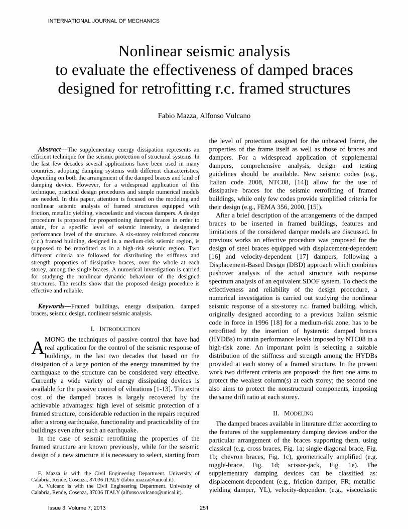
the features of the supplementary damping devices and/or the particular arrangement of the braces supporting them, using classical (e.g. cross braces, Fig. 1a; single diagonal brace, Fig. 1b; chevron braces, Fig. 1c), geometrically amplified (e.g. toggle-brace, Fig. 1d; scissor-jack, Fig. 1e). The supplementary damping devices can be classified as: displacement-dependent (e.g., friction damper, FR; metallic-yielding damper, YL), velocity-dependent (e.g., viscoelastic
Nonlinear seismic analysis to evaluate the effectiveness of damped braces designed for retrofitting r.c. framed structures
Fabio Mazza, Alfonso Vulcano
A
INTERNATIONAL JOURNAL OF MECHANICS
Issue 3, Volume 7, 2013 251
damper, VE; viscous damper, VS) and self-centring (e.g. shape memory alloys, SMA). Apart from the system in Fig. 1a, where the braces are assumed to be slender enough to buckle elastically (negligible buckling load), in the other systems depicted in Figs. 1b-1e the braces are designed not to buckle. For clarity, referring to the schemes in Fig. 1, the properties of the system at a storey are indicated as follows: KB is the elastic stiffness of the brace(s); KD and CD are the elastic stiffness and viscous damping of the damper; KF and CF are the elastic stiffness and viscous damping of the frame.
(a)
(b)
(c)
(d)
(e)
Fig. 1. Typical arrangements of damped braces.
To simulate the behaviour of braced frames equipped with damping devices, suitable analytical models should be adopted. In addition, the models should be relatively simple to carry out the analysis with a reasonable computational effort. In what follows aspects of the analytical modeling are discussed only with reference to devices with displacement- and velocity-dependent damping [1-3].
A. Displacement-dependent damping FR and YL dampers have a stable hysteretic behaviour and
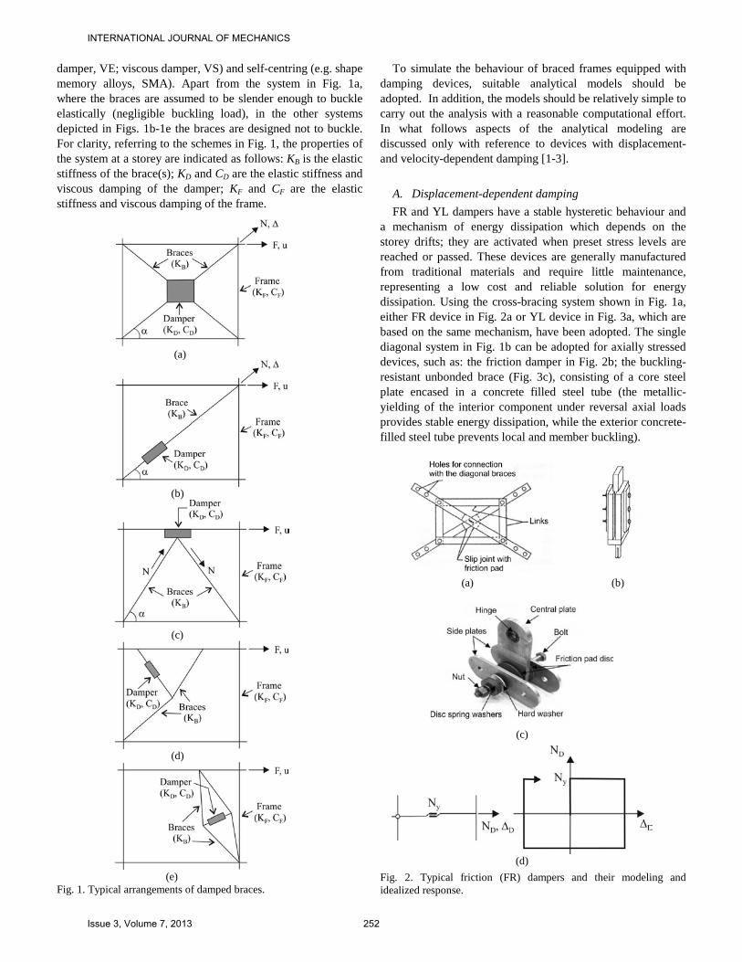
a mechanism of energy dissipation which depends on the storey drifts; they are activated when preset stress levels are reached or passed. These devices are generally manufactured from traditional materials and require little maintenance, representing a low cost and reliable solution for energy dissipation. Using the cross-bracing system shown in Fig. 1a, either FR device in Fig. 2a or YL device in Fig. 3a, which are based on the same mechanism, have been adopted. The single diagonal system in Fig. 1b can be adopted for axially stressed devices, such as: the friction damper in Fig. 2b; the buckling-resistant unbonded brace (Fig. 3c), consisting of a core steel plate encased in a concrete filled steel tube (the metallic-yielding of the interior component under reversal axial loads provides stable energy dissipation, while the exterior concrete-filled steel tube prevents local and member buckling).
(a) (b)
(c)
(d)
Fig. 2. Typical friction (FR) dampers and their modeling and idealized response.
INTERNATIONAL JOURNAL OF MECHANICS
Issue 3, Volume 7, 2013 252

Moreover, damping devices can be also located between the top of chevron braces and beam mid-span (Fig. 1c), e.g.: a FR device of the kind in Fig. 2c; a YL device, consisting of multiple X-shaped steel plates (Fig. 3b). As shown in Fig. 3d, the behaviour of a YL device can be idealized by a bilinear law, which specializes as a rigid-plastic one for a FR device (Fig. 2d).
The design parameters of the FR and YL dampers are summarized below: (a) FR damper:
Ny=slip load; Nmax=tension-brace force at frame-yielding onset; N*=Ny/Nmax=slip-load ratio;
(b) YL damper: Ny=yield load; N*=Ny/Nmax=yield-load ratio; KD=initial damper stiffness; rD=damper stiffness ratio.
In the case of HYDs (using YL dampers), the lateral stiffness of the damped braces (KDB) can be expressed as for an in-series model depending on the brace stiffness, KB, and the elastic stiffness of the damper, KD:
.DBB D
1K =1 K +1 K
(1)
Note that (1) specializes as KDB=KD, in the case of a FR damper (KD→∞ ).
(a) (b)
(c)
(d)
Fig. 3. Typical metallic-yielding (YL) dampers and their modeling and idealized response.
B. Velocity-dependent damping VE and VS devices dissipate energy, depending on the
velocity of motion, due to viscoelasticity and/or viscosity of elastomers or fluids; for these devices the dissipated energy is a linear or nonlinear function of the load frequency and temperature. A typical viscoelastic device consists of layers of polymers or glassy substances bonded with steel plates (Figs. 4a,b); it dissipates energy through heat loss when subjected to direct shearing of the viscoelastic material layers. Viscoelastic or pure viscous fluid dampers consist of a moving piston immersed in a more or less viscous (compressible or incompressible) fluid (Fig. 5a).
The design parameters of the velocity-dependent dampers are summarized below: (a) VE damper (e.g. polimer layer):
CD=effective damping coefficient; K'D=G'A/h=storage stiffness; K''D=G''A/h=loss stiffness; G'=shear-storage modulus; G''=shear-loss modulus; A/h=shear area/total thickness; ηD=K''D/K'D=loss factor (within the range 0.8÷1.5).
(b) VS damper: CD=damping coefficient; β=0-2 (β=1 for linear fluid damper);
βD D D DN =CΔ sign Δ (t) .
(a)
(b)
(c)
Fig. 4. Typical viscoelastic (VE) dampers and their modeling and idealized response.
INTERNATIONAL JOURNAL OF MECHANICS
Issue 3, Volume 7, 2013 253

As shown in Fig. 4c, the behaviour of a VE device can be simulated by a six-element generalized model (GM), which is a combination of the classical Kelvin and Maxwell models (KM and MM) [19, 20]. The GM allows, in comparison to KM and MM, a better description of the material properties depending on the frequency. The storage (K'D) and loss (K"D) stiffnesses can be expressed, for a given circular frequency ω, as functions of the constants characterizing the behaviour of the springs and dashpots constituting the GM:
2 2
D,1 D,1 D,2 D,22D D,32 2 2 2 2 2
D,1 D,1 D,2 D,2
K C K CK =ω + +K
ω C +K ω C +K
′
(2)
.2 2D,1 D,1 D,2 D,2
D D,32 2 2 2 2 2D,1 D,1 D,2 D,2
K C K CK =ω + +C
ω C +K ω C +K
′′
(3)
Moreover, the storage (KDB) and loss (K"DB) horizontal stiffnesses of the VE damped bracing system, as shown by Fu and Kasai [21] assuming a sinusoidal motion, can be expressed respectively as:
( )( )
2B D B D B D
DB 2 2B D D
K +K K K +K KK =
K +K +K
′ ′ ′′
′ ′′ (4)
( ) .
2B D
DB 2 2B D D
K KK =K +K +K
′′′′
′ ′′ (5)
Finally, a VS device (Fig. 5b) can be considered as a
specialization of a VE device assuming K'D=0. It is interesting to note that, for the same maximum values of force (ND,0) and displacement (∆D,0), the energy dissipation increases for decreasing values of the parameter β (Fig. 5b). Specifically, a rigid-plastic response independent of the velocity of motion is obtained for β=0.
(a)
(b)
Fig. 5. Typical viscous (VS) damper and its modeling and idealized response.
III. METHOD OF ANALYSIS A computer code was prepared in order to simulate the
response of a reinforced concrete (r.c.) framed building with damped braces. To simulate the behaviour of the r.c. frame member, a lumped plasticity model constituted of two components (one elastic-perfectly plastic and the other elastic-linear) is considered, assuming a bilinear moment-curvature law with a suitable value of hardening ratio (e.g., 5%). The effect of the axial load on the ultimate bending moment of the columns (M-N interaction) is also considered, assuming fully elastic axial strains, while the shear deformation is neglected. At each step of the analysis, the elastic-plastic solution is evaluated in terms of the initial state and the incremental load on the basis of a holonomic law, as a solution of the Haar-Kàrmàn principle [22-25].
More specifically, by imposing plastic conditions on the bending moments (mi and mj) at the end sections (i and j) of each frame element, the elastic-plastic solution can be obtained considering, among the equilibrated internal forces m=(mi, mj)T the one which proves to be closest to the elastic solution mE=(mEi, mEj)T, satisfying the complementary energy minimum principle for the self-equilibrated internal forces (m−mE). The solution can be obtained by using the three-step algorithm illustrated in Fig. 6 and Eqns. (6a)-(6c), where My1 (My4) and My3 (My2) represent, respectively, the yield moments corresponding to the two loading directions at top and bottom of the end section i (j).
Fig. 6. Elastic-plastic solution of a r.c. frame member according to Haar-Kàrmàn principle [22, 25].
{ }{ }i y3 y1 Eim =max M ,min M , m−′ (6a)
( )j y4 y2 Ej Ei i1m =max M ,min M ,m m m2
− − − ′
(6b)
( )i y3 y1 Ei Ej j1m =max M , min M ,m m m2
− − −
(6c)
A. Nonlinear static analysis The static equilibrium equations can be expressed as
[ ]= (λ)f u p (7)
INTERNATIONAL JOURNAL OF MECHANICS
Issue 3, Volume 7, 2013 254

corresponding to a nonlinear implicit system in the unknown displacement vector u, where f and p represent the structural reaction vector and the external load vector, respectively, and λ is the load multiplier. The convergence problem when approaching the ultimate point of the equilibrium path is avoided assuming a curvilinear arc-length abscissa as description parameter in the {u, λ} space [26]. The main idea of the iteration scheme is to introduce the load multiplier λ explicitly as another unknown. To fix the arc-length, the orthogonality condition between the iterative correction { u , λ } and the total step increment { Δu , Δλ } is imposed. The
following residual iteration scheme can be used to solve (7):
( )j j j=λ -r p f u (8)
TjΔ +γΔλλ=0u K u (9)
where Kj, representing the secant stiffness matrix in the j-th iteration loop, and γ (a convenient choice could be γ=0) are appropriate metric factors.
B. Nonlinear dynamic analysis The dynamical equilibrium equations can be expressed as:
( ) ( ) ( ) ( )− gt + t + t = u tMu Cu f u M i (10)
corresponding to a nonlinear implicit system in the unknown velocity vector u , with: M being the mass matrix, u and ü the displacement and acceleration vectors, f the structural reaction vector, i the vector of the influence coefficient and üg the horizontal ground acceleration. According to the Rayleigh hypothesis, the damping matrix C is assumed to be a linear combination of the mass and the stiffness matrices, assuming a suitable damping ratio (e.g. 5%) associated with two control frequencies (or modes). To obtain the solution of (10), the following residual iteration scheme is used [22, 27]:
( ) ( )− − − −
(j) (j)(j)1 0 0 0 1 1
1 1= +α Δt + +α Δt2 2
r q q s p s p (11)
(j+1) (j) (j)1 1= -u u Hr (12)
in which the indexes 0 and 1 refer, respectively, to the beginning and the end of the generic time step, q=M u is the momentum vector, s=f[u]+C u , while α and β are suitable functions of the time step ∆t. The convergence of the iterative process is assured adopting the iteration matrix
-12
E1 1 1= + +α +β Δt + +α Δt2 2 2
H M K C (13)
where KE is the elastic stiffness matrix.
IV. DESIGN OF THE UNBRACED AND DAMPED BRACED R.C. STRUCTURES
A typical six-storey residential building with a r.c. framed structure (Fig. 7a) is considered as primary structure. The lengths of the frame members are shown in Fig. 7. The size of the sections of girders and columns are reported in Tables 1 and 2, respectively. Floor masses and first-mode (horizontal) components (φ1, φ2, ...., φn) are also reported in Table 1. The first three vibration periods of the unbraced frame and the corresponding effective masses (expressed as a percentage of the total mass, mt) are: T1=0.762s and m1=74.1%mt; T2=0.311s and m2=16.2%mt; T3=0.245s and m3= 5.6%mt.
(a) Plan of the unbraced framed structure (UF).
(b) Plan of the damped braced structure (DBF).
(c) Elevation of a damped braced plane frame.
Fig. 7. Unbraced and damped braced r.c. framed structures (dimensions in cm).
INTERNATIONAL JOURNAL OF MECHANICS
Issue 3, Volume 7, 2013 255

The primary framed building is designed according to the Italian Seismic Code in force in 1996 [18], for a medium-risk seismic region (seismic coefficient: C=0.07) and a typical subsoil class (coefficients: R=ε=β=1). The gravity loads are represented by a dead load of 4.2 kN/m2 at the top floor and 5.0 kN/m2 at the other floors, and a live load of 2.0 kN/m2 at all the floors. Masonry infill walls, regularly distributed in elevation along the perimeter (see Fig. 7a), are considered assuming an average weight of about 2.7 kN/m2. A cylindrical compressive strength of 25 N/mm2 for the concrete and a yield strength of 375 N/mm2 for the steel are considered. The design is carried out to comply with the ultimate limit states. Detailing for local ductility is also imposed to satisfy minimum conditions for the longitudinal bars of the r.c. frame members: for the girders, a tension reinforcement ratio nowhere less than 0.37% is provided and a compression reinforcement not less than half of the tension reinforcement is placed at all the sections; for a section of each column a minimum steel geometric ratio of 1% is assumed, supposing that the minimum reinforcement ratio corresponding to one side of the section be about 0.35%.
Table 1. Section dimensions (in cm) of girders, floor masses and first-mode shape of the primary framed structure.
Storey Girders Floor masses (kNs2/m) First-mode shape (φ)
6 30x45 171 1.00 5 30x45 245 0.83 4 30x50 257 0.63 3 30x55 264 0.44 2 40x60 285 0.26 1 40x70 301 0.13
Table 2. Section dimensions (in cm) of columns of the primary framed structure.
Lateral frames Interior frames and central frame
Storey Exterior columns
Interior columns
Exterior columns
Interior columns
6 30x30 30x30 30x30 30x30 5 30x35 30x40 40x30 40x40 4 30x40 30x50 50x30 50x50 3 30x40 30x50 50x30 50x50 2 30x50 30x60 60x30 60x60 1 30x50 30x60 60x30 60x60
For the purpose of retrofitting the test structure from a
medium-risk region to a high-risk seismic region, diagonal steel braces equipped with dampers are inserted, at each storey, as indicated in Figs. 7b and 7c. For brevity, only the case of YL dampers (HY damped braces, HYDBs) is considered. The design of the damped braces is carried out considering seismic loads provided by NTC08 for a high-risk seismic region (peak ground acceleration on rock: ag=0.27g; maximum spectrum amplification coefficient: F0=2.5) and subsoil class B on a level ground (site amplification factor: S=SSST=1.13; PGA=1.13x0.27g=0.31g). The design of the damped braces is carried out by using a Direct-Displacement-
Based (DDB) procedure already proposed by the authors [16]. The main steps of the proposed DDB design method are summarized in Fig. 8, where an iterative procedure is needed to solve steps 3-5. Further details can be found in [16].
Fig. 8. Flow-chart of the design procedure of HYDBs [16].
INTERNATIONAL JOURNAL OF MECHANICS
Issue 3, Volume 7, 2013 256

The following values are assumed for the design: ductility of the frame, μF=1.5, and stiffness hardening ratio, rF=0%; ductility of the damper, μD=10, and stiffness hardening ratio, rD=0%. The properties of the dissipative braces are evaluated supposing a brace which is rigid enough so that its deformability can be neglected (then, according to (1), it can be assumed that KDB=KD). Two different criteria are used at each storey to distribute the stiffness and strength properties of the damped braces (obtained as a whole) among the actual braces provided into the lateral and central frames along the assumed direction of the ground motion (see Fig. 7b and Fig. 7c).
According to the first criterion, which is consistent with the design procedure already proposed [16], the distribution of the global stiffness between the braces of a storey is obtained assuming the contribution of the dissipative braces is proportional to the ratio between ultimate shear and design shear, calculated for the weakest column of the considered plane frame at that storey (Fig. 7c). Then, the strength distribution is assumed to be proportional to the stiffness distribution.
Alternatively, the second criterion, which is a variant of the above design procedure combined with the first criterion, aims to get, on the whole, a regular damped braced structure in terms of stiffness and strength [28]. For this purpose, an inverted triangular mode shape, consistent with a drift ratio constant at each storey, is considered. To make the two criteria comparable, both the sum of all the storey stiffnesses and the yield shear at the first storey were assumed to be the same for both the criteria.
Table 3. Properties of the HYDBs for the first criterion (structure DBF(1)).
Yield load (kN) Elastic stiffness (kN/m) Storey Central
frame Exterior frames
Central frame
Exterior frames
6 56.33 50.13 74634 66411 5 131.16 105.94 144710 116891 4 193.43 148.73 231659 178125 3 233.94 181.83 285272 221727 2 292.30 186.29 514332 327799 1 323.14 188.88 553559 323556
Table 4. Properties of the HYDBs for the second criterion (structure DBF(2)).
Yield load (kN) Elastic stiffness (kN/m) Storey Central
frame Exterior frames
Central frame
Exterior frames
6 28.39 25.26 11707 104116 5 153.53 124.01 227776 183988 4 167.20 128.56 302062 232258 3 274.48 213.34 361247 280778 2 127.05 80.97 395406 252004 1 323.14 188.88 351956 205719
The distribution of stiffness properties among the damped
braces of a storey is made as for the first criterion; then
strength properties are distributed at each storey assuming an elastic behaviour under the lateral forces according to the mode shape assumed above. The properties of the HYDBs obtained according to the proposed two criteria are reported in Table 3 and 4. The marks DBF(1) and DBF(2) identify the structures designed according to the two criteria.
V. NUMERICAL RESULTS To check the effectiveness and reliability of the design
procedure and criteria illustrated above, a numerical investigation is carried out evaluating the nonlinear dynamic response of the primary and damped braced structures considered in Section IV when subjected to sets of real and artificial ground motions. More precisely, sets of seven real motions selected according to the procedure proposed by Iervolino et al. [29], and sets of three artificial motions generated as proposed by Gasparini and Vanmarcke [30], are considered in order to match (on average) the design spectra assumed by NTC08 for different limit states (damage, SLD; life safety, SLV; collapse, SLC).
(a) Girders.
(b) Columns.
Fig. 9. Maximum ductility demand for serviceability limit state (SLD).
Because of the structural symmetry and assuming the floor
slabs to be infinitely rigid in their own plane, the entire structure is idealized by an equivalent plane frame along the
INTERNATIONAL JOURNAL OF MECHANICS
Issue 3, Volume 7, 2013 257

considered horizontal motion direction. The nonlinear dynamic analyses are carried out by a step-by-step procedure, assuming elastic-perfectly laws to simulate the response of the r.c. frame members and hysteretic dissipative braces; in particular for the columns, the effect of the axial load on the ultimate moment is taken into account.
The maximum ductility demand on girders and columns of the unbraced structure and structure DBF(1) under the set of real motions for different limit states are compared in Figs. 9-11. More specifically, the damped braces of the structure DBF(1) were designed according to the first criterion discussed in Section IV. All the following results are obtained as an average of those separately obtained for the sets of real or artificial motions corresponding to a limit state.
As can be observed, the reduction in the ductility demand due to the insertion of damped braces, in comparison with the case of the unbraced frame, is (for many frame members) even more than 100% for both serviceability (i.e. SLD, Fig. 9) and ultimate (i.e. SLV, Fig. 10, and SLC, Fig. 11) limit states. However, under strong ground motions (as in SLV and SLC) some columns can undergo a comparable ductility demand for UF and DBF(1) structures, due to high variation in the axial force inducing a reduction in the flexural capacity (e.g., for corner columns, subjected to rather low gravity loads).
(a) Girders.
(b) Columns.
Fig. 10. Maximum ductility demand for ultimate limit state (SLV).
A comparison of the curves obtained for real and artificial motions (SLV) is reported in Fig. 12. In particular, the curves in Figs. 12a and 12b have been obtained for DBF(1) as an average of the maximum values for all the critical (end) sections of the frame members considering both the loading directions (i.e., the average of four values is considered for each member).
It is interesting to note that, although the distribution of the ductility demand to the UF members is different for the two kinds of motion due to the different frequency content, the target values assumed for designing the damped braces (i.e., μF=1.5, μD=10) are close enough to the obtained values, with slightly more conservative results for dampers (Fig. 12d). However, this also depends on the value selected for the equivalent damping ratio, because a reduction factor (κ=0.33) was assumed for the equivalent viscous damping due to hysteresis of the framed structure, to take into account the degradation of r.c. members, even though a bilinear model was used for the analyses. On the other hand, this can account for the damping overestimation by the Jacobsen method and the scattering of spectral values for real motions, which can be higher than the design spectral values [31].
(a) Girders.
(b) Columns.
Fig. 11. Maximum ductility demand for ultimate limit state (SLC). A comparison between curves obtained for DBF(1) and
DBF(2) structures is reported in Fig. 13. In Figs. 13a, b, c the curves for UF structure are also reported.
INTERNATIONAL JOURNAL OF MECHANICS
Issue 3, Volume 7, 2013 258

(a) Girders.
(b) Columns.
(c) Maximum drift ratio.
(d) Hysteretic dampers.
Fig. 12 Comparison of results obtained for DBF(1) subjected to real and artificial motions (SLV).
(a) Girders.
(b) Columns.
(c) Maximum drift ratio.
(d) Hysteretic dampers.
Fig. 13. Comparison of results obtained for DBF(1) and DBF(2) subjected to real motions (SLV).
INTERNATIONAL JOURNAL OF MECHANICS
Issue 3, Volume 7, 2013 259

As shown, the results for DBF(1) and DBF(2) structures are comparable with regard to the ductility demand to frame members and drift ratio (Figs. 13a, b, c), while the ductility demand to dampers (Fig. 13d) is greater at the second and top storeys of structure DBF(2), where the strength of dampers is rather low in comparison with that at other storeys (see Table 4). However, it should be noted that the primary structure is rather regular; there appears to be no benefits (i.e. uniform drift ratio and consequent control of damage in nonstructural components) in using the second criterion.
VI. CONCLUSION A step-by-step procedure for the nonlinear seismic analysis
of framed structures equipped with damped braces was presented. For this purpose, suitable models were adopted for simulating the response of a frame member and that of different kinds of dampers (i.e. friction, metallic yielding, viscoelastic, viscous) under strong ground motions. A design procedure was proposed for proportioning damped braces in order to retrofit a r.c. framed structure. Two criteria were followed for distributing the stiffness and strength properties of dissipative braces at each storey. The results of the nonlinear seismic analysis, with reference to six-storey regular structures with HYDBs, showed the effectiveness and reliability of the proposed design procedure. However, under strong ground motions (as in SLV and SLC) some columns can undergo a ductility demand comparable to that in the unbraced structure, due to high variation in the axial force inducing a reduction in the flexural capacity. Both the two above criteria led to comparable values of the ductility demand on frame members and the drift ratio. But the second criterion led to some peak values of the ductility demand on dampers; on the other hand, there appeared to be no benefits of this criterion (e.g. control of damage in nonstructural components) because the primary structure considered was rather regular. Further studies are needed before using the proposed design procedure in cases of irregular primary buildings.
ACKNOWLEDGMENT The present work was financed by RELUIS (Italian network
of university laboratories of earthquake engineering), according to “convenzione D.P.C. – RELUIS 2010-2013, task 2.3.2”.
REFERENCES [1] T.T. Soong, and G.F. Dargush, “Passive energy dissipation systems in
structural engineering,” J. Wiley & Sons, Chichester, England, 1997. [2] C. Christopoulos, and A. Filiatrault, “Principles of passive
supplemental damping and seismic isolation,” IUSS Press, Istituto Universitario di Studi Superiori di Pavia (Italy), 2006.
[3] F. Mazza, and A. Vulcano, “Sistemi di controllo passivo delle vibrazioni,” in Progettazione sismo-resistente di edifici in cemento armato, Città Studi Edizioni, Italy, 2011, vol. 11, pp. 525-575.
[4] F. Mazza, A. Vulcano, M. Mazza, and G. Mauro. “Modeling and nonlinear seismic analysis of framed structures equipped with damped braces,” Recent Researches in Information Science and Applications. WSEAS 2013, Milan, Italy, January 9-11, 2013, ISBN: 978-1-61804-150-0, ISSN: 1790-5109.
[5] F.C. Ponzo, A. Di Cesare, D. Nigro, A. Vulcano, F. Mazza, M. Dolce, C. Moroni, “JET-PACS project: dynamic experimental tests and numerical results obtained for a steel frame equipped with hysteretic damped chevron braces,” Journal of Earthquake Engineering, 2012, vol. 16, pp. 662-685.
[6] J. Molina, S. Sorace, G. Terenzi, G. Magonette, and B. Viaccoz, “Seismic tests on reinforced concrete and steel frames retrofitted with dissipative braces,” Earthquake Engineering and Structural Dynamics, 2004, vol. 33(12), pp. 1373-1394.
[7] A. Baratta, I. Corbi, O. Corbi, R.C. Barros, and R. Bairrão, “Shaking table experimental researches aimed at the protection of structures subject to dynamic loading,” The Open Construction and Building Technology Journal, 2012, vol. 6, pp. 355-360.
[8] A. Baratta, and I. Corbi, “Optimal design of base-isolators in multi-storey buildings,” Journal Computers and Structures, 2004, vol. 82(23-26), pp. 2199-2209.
[9] D. Foti, L.M. Bozzo, F. Lopez-Almansa, “Numerical efficiency assessment of energy dissipators for seismic protection of buildings,” Earthquake Engineering and Structural Dynamics, Wiley & Sons, ltd., Chichester, UK, 1998, vol. 27, pp. 543-556.
[10] A. Baratta, and O. Corbi, “On the dynamic behaviour of elastic-plastic structures equipped with pseudoelastic SMA reinforcements,” Journal of Computational Materials Science, 2002, vol. 25(1-2), pp.1-13.
[11] I. Corbi, FRP reinforcement of masonry panels by means of c-fiber strips, Journal Composites Part B, 2013, vol.47, pp.348-356.
[12] F. Mazza, and A. Vulcano, “Nonlinear response of rc framed buildings with isolation and supplemental damping at the base subjected to near-fault earthquakes,” Journal of Earthquake Engineering, 2009, vol. 13(5), pp. 690-715.
[13] F. Mazza, A. Vulcano, and M. Mazza, “Nonlinear dynamic response of rc buildings with different base-isolation systems subjected to horizontal and vertical components of near-fault ground motions”, The Open Construction & Building Technology Journal, 2012, vol. 6, p. 373-383, ISSN: 1874-8368.
[14] Italian Ministry of Infrastructures. Nuove norme tecniche per le costruzioni e relative istruzioni. D.M. 14-01-2008 e Circolare 02-02-2009, n. 617/C.S.LL.PP. (in italian).
[15] Federal Emergency Management Agency (2000). FEMA 356. Prestandard and commentary for the seismic rehabilitation of buildings. American Society of Civil Engineers, Reston, Virginia.
[16] F. Mazza, and A. Vulcano, “Displacement-based seismic design procedure for framed buildings with dissipative braces. (a) Part I: Theoretical formulation; (b) Part II: Numerical results,“ In: 2008 Seismic Engineering International Conference commemorating the 1908 Messina and Reggio Calabria Earthquake (MERCEA08), Reggio Calabria (Italy), 2008, American Institute of Physics Conference Proceedings, U.S.A, vol. 1020 (part two).
[17] F. Mazza, and A. Vulcano, “Displacement-based design of dissipative braces at a given performance level of a framed building,” Procs. of the 14th World Conference on Earthquake Engineering, Beijing, China, 2008. paper n. 14-53.
[18] Italian Ministry of Public Works. Norme tecniche per le costruzioni in zone sismiche e relative istruzioni. D.M. 16-01-1996 e Circolare M.ro LL.PP. 10-04-1997, n. 65/AA.GG. (in italian).
[19] F. Mazza, and A. Vulcano, “Control of the along-wind response of steel framed buildings by using viscoelastic or friction dampers,” Wind & Structures, 2007, vol. 10(3), pp. 233-247.
[20] F. Mazza, and A. Vulcano, “Control of the earthquake and wind dynamic response of steel-framed buildings by using additional braces and/or viscoelastic dampers,” Earthquake Engineering & Structural Dynamics, 2011, vol. 40, pp. 155-174.
[21] Y. Fu, and K. Kasai, “Comparative study of frames using viscoelastic and viscous dampers,” Journal of Structural Engineering, ASCE, 1998, vol. 124(5), pp. 513-522.
[22] A. Vulcano, “Analisi sismica di strutture intelaiate piane in campo elasto-plastico,” (in italian). Procs. 1° Convegno di Ingegneria Sismica in Italia, Udine, 1980; CISM (International Centre for Mechanical Sciences) Courses and Lectures, n. 271, Springer Verlag, 1981.
[23] F. Mazza, and M. Mazza, “Nonlinear analysis of spatial framed structures by a lumped plasticity model based on the HaarKàrmàn principle,” Computational Mechanics, 2010, vol. 45, p. 647-664.
INTERNATIONAL JOURNAL OF MECHANICS
Issue 3, Volume 7, 2013 260

[24] F. Mazza, and M. Mazza, “Nonlinear modeling and analysis of r.c. framed buildings located in a near-fault area,” The Open Construction & Building Technology Journal, 2012, vol. 6, p. 346-354.
[25] F. Mazza, and A. Vulcano, “Nonlinear dynamic response of r.c. framed structures subjected to near-fault ground motions,” Bulletin of Earthquake Engineering, vol. 8, p. 1331-1350, ISSN:1570-761X.
[26] E. Riks, “An incremental approach to the solution of snapping and buckling problems,” International Journal of Solids and Structures, 1979, vol. 15, pp. 529–551.
[27] R. Casciaro, “Time evolutional analysis of nonlinear structures,” Meccanica, 1975, vol. 3(X), pp. 156-167.
[28] F. Mazza, M. Mazza and A. Vulcano, “Displacement-based design of hysteretic dissipative braces for the seismic retrofitting of r.c. framed buildings,” Procs of the 15th World Conference on Earthquake Engineering, Lisboa (Portugal), 2012.
[29] I. Iervolino, G. Maddaloni, and E. Cosenza, “Eurocode 8 compliant record sets for seismic analysis of structures,” Journal of Earthquake Engineering, 2008, vol. 12(1), pp. 54-90.
[30] D. Gasparini, and E. Vanmarcke, “Simulated earthquake motions compatible with prescribed response spectra,” Massachusetts Institute of Technology, Department of Civil Engineering, U.S.A., 1976.
[31] F. Mazza, and A. Vulcano, “Equivalent viscous damping for displacement-based aseismic design of damped braced frames,” Procs. of the 14th European Conference on Earthquake Engineering, Skopije, Republic of Macedonia, 2010, paper n. 336.
INTERNATIONAL JOURNAL OF MECHANICS
Issue 3, Volume 7, 2013 261