nonmechanical control of solids flow in chemical … · nonmechanical control of solids flow in...
TRANSCRIPT

Nonmechanical Control of Solids
Flow in Chemical Looping Systems
Ted Knowlton
Particulate Solid Research, Inc.
NETL 2011 Workshop on
Multiphase Flow Science
August 16 – 18, 2011
Pittsburgh, PA
Proprietary and Confidential
2
Chemical Looping Systems
There are Many Different Types of Chemical Looping
Systems That are Being Developed or Proposed
All Involve Substantial Flows of Solids Around the
System
Proprietary and Confidential
3
Chemical Looping Systems
Typically, the Temperatures Involved in Chemical
Looping Systems are too High to Easily Use
Mechanical Valves for Control
Therefore, Nonmechanical Means are Being Employed
to Control the Solids Flow Rates Around the Systems
Proprietary and Confidential
4
Chemical Looping Systems
How Are the Solids Being Controlled in These
Systems Using Nonmechanical Means?
This Depends on the Type of Flow System Used as
Well as the Particle Size Used in the System
Proprietary and Confidential
5
Chemical Looping Systems
To Evaluate the Different Nonmechanical Techniques
it is Necessary to Understand the Principles Behind
Nonmechanical Systems – but Often There is a Lack
of Understanding About How They Operate
Therefore, Several Basic Principles of Nonmechanical
Systems will be Reviewed Before Evaluating Several
Different Flow Systems

Proprietary and Confidential
6
Nonmechanical Solids Flow Devices Fall
Into Two Categories:
1. Solids Flow Control Devices (Valves)
Example: L-Valve
2. Solids Flow-Through Devices Which
DO NOT CONTROL Solids Flow (They
Automatically Pass Solids Through
Them)
Examples: Loop Seal
Automatic “L-Valve”
Nonmechanical Solids Flow Devices

Proprietary and Confidential
7
10 20 50 100 200 500 1,000 2,000100
200
300
500
1,000
2,000
3,000
5,000
10,000
d , Microns
, K
g/m
GELDART'S POWDER CLASSIFICATION
A
B
C
D
A: Aeratable ( U > U )
B: Bubbles Above U ( U = U )
C: Cohesive
D: Spoutable
mb mf
mb mf
3
p
pg
-
Material Has a Significant Deaeration Time
Applies at Ambient Conditions
(Geldart, D. Powder Technology, 1, 285, 1973)
(FCC Catalyst)
(500-micron Sand)
(Flour, Fly Ash)
(Wheat, 2000-micron Polyethylene Pellets)
mf
Proprietary and Confidential
8
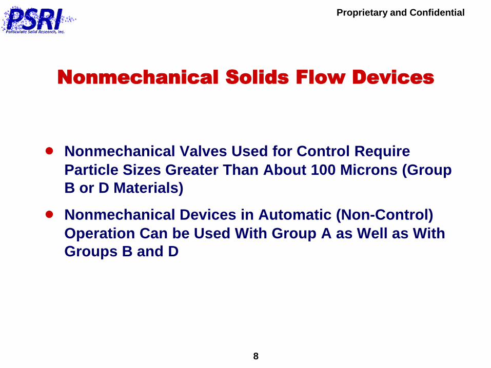
Nonmechanical Solids Flow Devices
Nonmechanical Valves Used for Control Require
Particle Sizes Greater Than About 100 Microns (Group
B or D Materials)
Nonmechanical Devices in Automatic (Non-Control)
Operation Can be Used With Group A as Well as With
Groups B and D

Proprietary and Confidential
9
Nonmechanical Solids Flow Devices
Why do Nonmechanical Valves Not Work Well With
Group A Materials?
This is Because Group A Materials Do Not Defluidize
Instantaneously When Gas is Shut Off to a Fluidized
Bed, and They Retain Their Fluidity for a Few Seconds
Thus, When Group A Solids are Poured Into a
Nonmechanical Valve, the Solids Retain Their Fluidity
and Flow Through the Valve Like Water (Uncontrollably)

Proprietary and Confidential
10
NONMECHANICAL VALVES USED FOR
SOLIDS FLOW CONTROL
Nonmechanical Valves are Devices That Use Only Aeration Gas in Conjunction With Their Geometrical Shape to Control the Flow Rate of Solids Through Them
1. Have no Moving Parts (Other than the Solids)
2. Are Very Inexpensive
3. Can Feed Solids Into a Dense-Phase or Dilute-Phase Environment
Proprietary and Confidential
11
NONMECHANICAL VALVE OPERATION
The Most Common Nonmechanical Valve
Used to Control Solids Flow is the L-Valve
Proprietary and Confidential
12
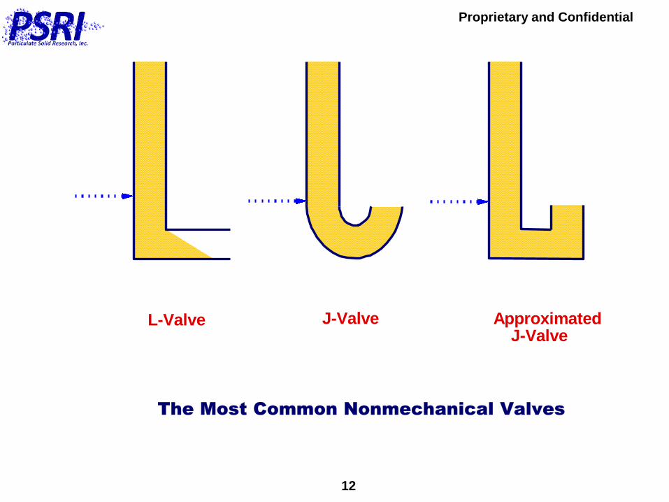
The Most Common Nonmechanical Valves
L-Valve J-Valve Approximated J-Valve
Proprietary and Confidential
13
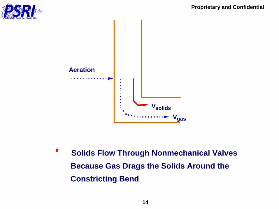
NONMECHANICAL VALVE OPERATION
Solids Flow Rate Through a Nonmechanical
Valve is Controlled By the Amount of
Aeration Gas That is Added to It
Proprietary and Confidential
14
Solids Flow Through Nonmechanical Valves
Because Gas Drags the Solids Around the
Constricting Bend
V
V
gas
solids
Aeration

Proprietary and Confidential
15
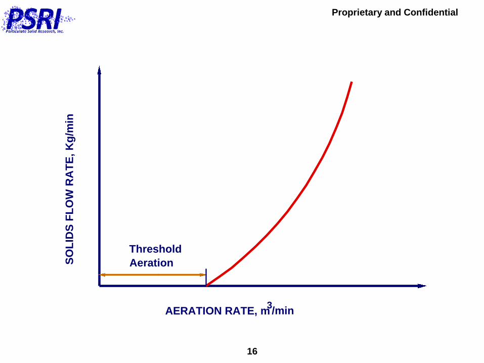
When Aeration Gas is Added to a Nonmechanical Valve, Solids Do Not Begin to Flow Immediately.
There is a Certain Threshold Amount of Aeration Which Must Be Added Before Solids Begin to Flow.
Solids Flow Through a Nonmechanical Valve Because of Drag Forces on the Particles Produced By the Aerating Gas.
Proprietary and Confidential
16
AERATION RATE, m3/min
SO
LID
S F
LO
W R
AT
E,
Kg
/min
Threshold
Aeration
Proprietary and Confidential
17
NONMECHANICAL VALVE OPERATION
Where Should Aeration be Added to an
L-Valve?
Proprietary and Confidential
18
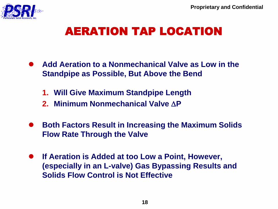
AERATION TAP LOCATION
Add Aeration to a Nonmechanical Valve as Low in the
Standpipe as Possible, But Above the Bend
1. Will Give Maximum Standpipe Length
2. Minimum Nonmechanical Valve DP
Both Factors Result in Increasing the Maximum Solids
Flow Rate Through the Valve
If Aeration is Added at too Low a Point, However,
(especially in an L-valve) Gas Bypassing Results and
Solids Flow Control is Not Effective

Proprietary and Confidential
19
0 0.2 0.4 0.6 0.8 1 1.2 1.4 1.6 1.80
2
4
6
8
10
12
14
16
18
20
L-Valve Aeration Rate, ACFM
So
lid
s F
low
Rate
, T
ho
usan
ds o
f lb
/hMaterial: Sand (260 microns)
Aeration Gas: Nitrogen
B
1
2
3
4
5Tap
Height Above
Centerline, in
1
2
3
4
5 24
18
12
6
0
B
Proprietary and Confidential
20
Understanding the Operation of Nonmechanical
Valves Depends Primarily on Two Things:
1. The Pressure Balance in the System
2. Understanding Packed-Bed Standpipe
Operation
Nonmechanical Solids Flow Devices
Proprietary and Confidential
21
A Standpipe is a Length of Pipe Through Which
Solids Flow by Gravity
The Primary Purpose of a Standpipe is to Transfer
Solids From a Low Pressure Region to a Higher
Pressure Region
Standpipes
Proprietary and Confidential
22
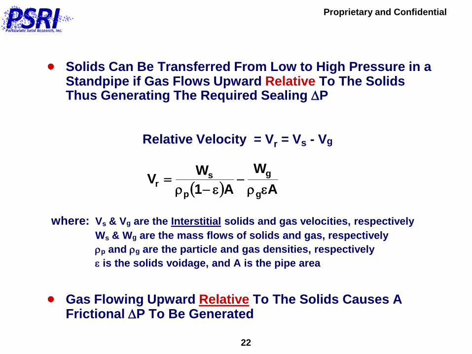
Solids Can Be Transferred From Low to High Pressure in a Standpipe if Gas Flows Upward Relative To The Solids Thus Generating The Required Sealing DP
Relative Velocity = Vr = Vs - Vg
where: Vs & Vg are the Interstitial solids and gas velocities, respectively
Ws & Wg are the mass flows of solids and gas, respectively
p and g are the particle and gas densities, respectively
e is the solids voidage, and A is the pipe area
Gas Flowing Upward Relative To The Solids Causes A Frictional DP To Be Generated
A
W
A1
WV
g
g
p
sr
e
e
Proprietary and Confidential
23
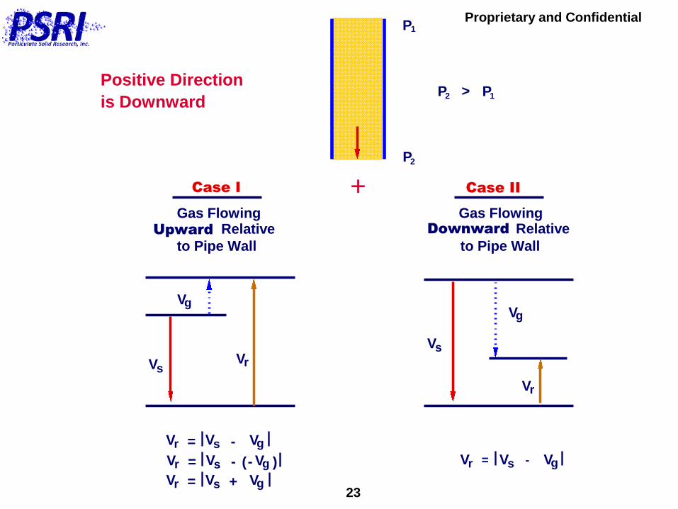
P
>
Case I Case II
Gas FlowingUpward
to Pipe Wall
Gas FlowingRelative
to Pipe Wall
V
V V
g
sr
2
DownwardRelative
Vs
Vr
Vg
P1
P1P2
Vr = Vs - Vg
Vr = Vs - VgVr = Vs - Vg(- )
Vr = Vs + Vg
+
Positive Direction
is Downward

Proprietary and Confidential
24
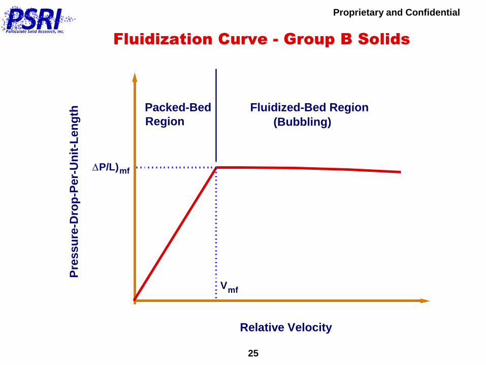
The Relationship Between DP/L And Vr is Determined
By the Fluidization Curve
This Curve is Usually Generated In A Fluidization
Column, But It Also Applies In Standpipes
Standpipes
Proprietary and Confidential
25
Relative Velocity
Pre
ss
ure
-Dro
p-P
er-
Un
it-L
en
gth
P/L)mf
Packed-Bed
Region
Fluidized-Bed Region
(Bubbling)
Vmf
D
Fluidization Curve - Group B Solids

Proprietary and Confidential
26
OVERFLOW UNDERFLOW
Underflow and Overflow Standpipes

Proprietary and Confidential
27
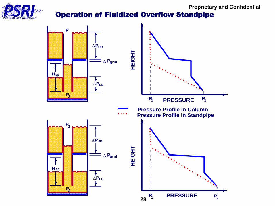
Many Standpipes are Fluidized Overflow Standpipes
Operation of These Standpipes is Easy to Understand,
and Non-Control Nonmechanical Devices (Loop Seals,
Seal Pots, etc.) Operate with This Type of Standpipe
Above Them
Standpipes
Proprietary and Confidential
28
DPLB
DPUB
Hsp
D Pgrid
P1
P2
DPLB
DPUB
Hsp
D Pgrid
P
1
P2PRESSURE
HE
IGH
T
PRESSURE
HE
IGH
T
Pressure Profile in ColumnPressure Profile in Standpipe
P PP 2
'
P'2
P1
Operation of Fluidized Overflow Standpipe

Proprietary and Confidential
29
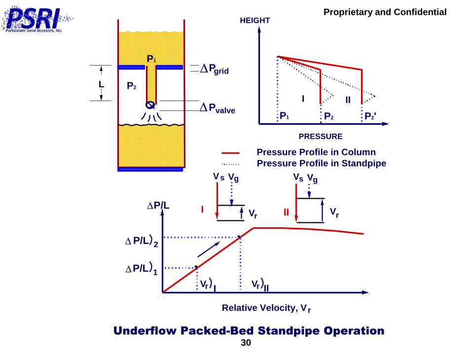
However, Nonmechanical Valves (Used to Control the
Solids Flow Rate) MUST Operate With a Packed Bed
Underflow Standpipe Above Them
How Does This Type of Standpipe Operate?
Standpipes
Proprietary and Confidential
30
DPgrid
HEIGHT
PRESSURE
Pressure Profile in Column
Pressure Profile in Standpipe
DP/L
Relative Velocity, V r
DPvalve
VrVr
DP/L 2
DP/L 1
Underflow Packed-Bed Standpipe Operation
L
P1
P2
P1 P2 P2'
I II
III
V V
V
V
V
V
rr
s sg g
III
Proprietary and Confidential
31
Gas Can Flow Either Upward or Downward (Relative
to the Pipe Wall) in the Packed Flow Standpipe Above
the L-Valve
The Direction of This Flow Depends on Particle Size
and the DP/L in the Standpipe Above the Valve
Nonmechanical Valves for
Solids Flow Control

Proprietary and Confidential
32
QT
Qext
Qsp
QT
Qsp
QT
=
Qext
Qext + Qsp QT = Qext - Qsp
Occurs With Small Particle Sizes
and/or At High Solids Flow Rates
Occurs With Large Particle Sizes
and/or At Low Solids Flow Rates
Most Common Situation

Proprietary and Confidential
33
Nonmechanical Valve Operation Also Depends on the
Pressure Balance Around the System
Not Designing the Pressure Balance Correctly can
Limit Nonmechanical Valve Operation by Affecting the
Solids Flow Rate
Nonmechanical Valves for
Solids Flow Control
Proprietary and Confidential
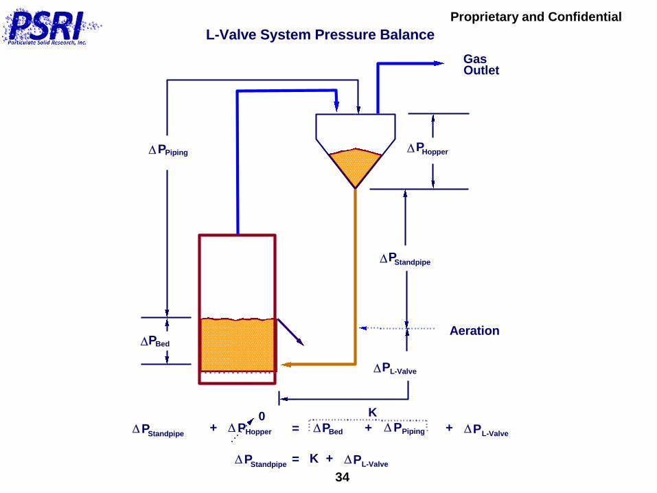
34
DPHopper
Aeration
GasOutlet
DPStandpipe
DPL-Valve
DPBed
DPPiping
DPStandpipe+ DPHopper = DPBed + DPPiping + DPL-Valve
L-Valve System Pressure Balance
DPStandpipe= K + DPL-Valve
0 K

Proprietary and Confidential
35
DP/L)mf
V
V
r
mf
DP/L
Maximum DP/L in Standpipe is:
DP/L )mf

Proprietary and Confidential
36
There is a Maximum DP/L That the Packed-Bed
Standpipe Can Develop -- (DP/L)mf
If Increase Solids Flow Rate, L-Valve ΔP
Increases and Standpipe ΔP Increases Until
DP/L Reaches (DP/L)mf

Proprietary and Confidential
37
A Short Standpipe Will Reach Its Maximum DP/L At a
Lower Solids Flow Rate Than a Longer Standpipe
Therefore, the Maximum Solids Flow Rate Through an
L-Valve Depends on the Length of the Standpipe
Above it
Proprietary and Confidential
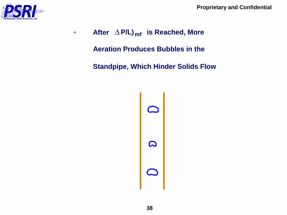
38
After is Reached, More
Aeration Produces Bubbles in the
Standpipe, Which Hinder Solids Flow
DP/L)mf
Proprietary and Confidential
39
Pressure Balance is Critical in Designing a
System Containing a Nonmechanical Valve:
1. If the Pressure Balance is Not Correct, the
Valve Will Not Operate Correctly
2. Example on Next Slide Shows Actual Case of
Someone Designing an L-Valve That Could
Have, But Did Not Work
Pressure Balance is Critical
Proprietary and Confidential
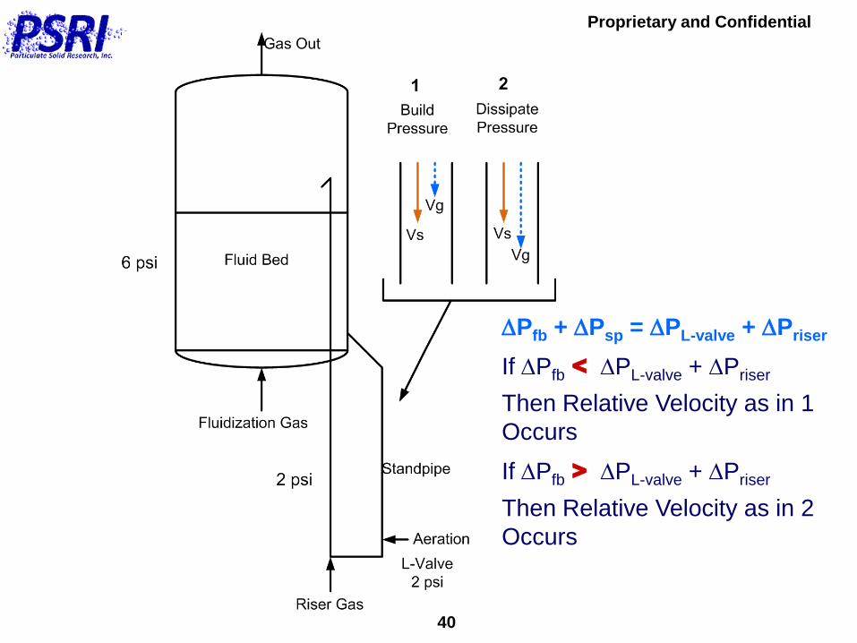
40
DPfb + DPsp = DPL-valve + DPriser
If DPfb < DPL-valve + DPriser
Then Relative Velocity as in 1
Occurs
If DPfb > DPL-valve + DPriser
Then Relative Velocity as in 2
Occurs
Proprietary and Confidential
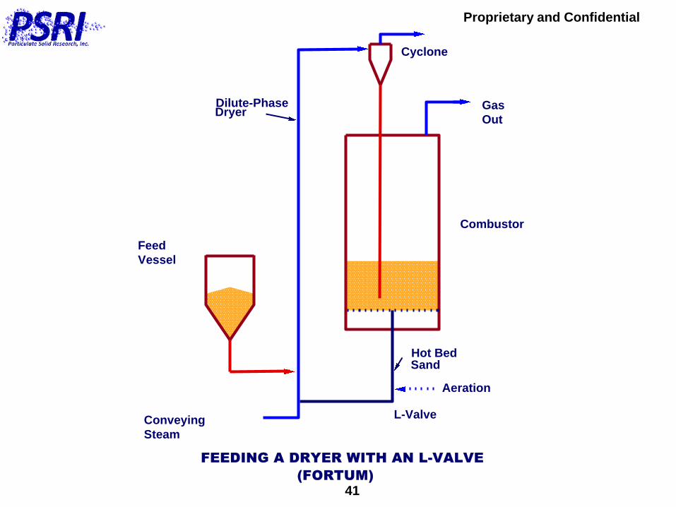
41
Combustor
Gas
Out
Cyclone
Feed
Vessel
Conveying
Steam
FEEDING A DRYER WITH AN L-VALVE
L-Valve
Dilute-PhaseDryer
Hot BedSand
(FORTUM)
Aeration

Proprietary and Confidential
42
The L-Valve Can be Designed to Prevent
System Gas from Exiting the Reactor
V Vg s

Proprietary and Confidential
43
It is also Possible to Prevent Aeration Gas
from Entering the Reactor
V Vg s
Proprietary and Confidential
44
NON-CONTROL (AUTOMATIC)
NONMECHANICAL SOLIDS FLOW
DEVICES
Provide a Pressure Seal (In Conjunction
With a Standpipe)
Operate With an Overflow Fluidized Bed
Standpipe Above Them

Proprietary and Confidential
45
AUTOMATIC NONMECHANICAL SOLIDS
FLOW DEVICES
Do Not Control Solids Flow
Automatically Adjust to Changes in the
Solids Flow Rate
Proprietary and Confidential
46
One of the Most Frequent Applications of
Automatic Nonmechanical Devices is in CFB
Systems Where a Loop Seal is Used to Recycle
Collected Solids from the Cyclone Back to the CFB

Proprietary and Confidential
47
SecondaryAir
Air In
Cyclone
BedDischarge
Primary Air
To Superheater
Coal-LimestoneFeed
Circulating Fluidized Bed Combustor
LoopSeal
Standpipe
Riser
Dilute Phase
Dense Phase
(Foster-Wheeler Type)

Proprietary and Confidential
48
Seal Pot Loop Seal
Fluidizing GasFluidizing Gas
Proprietary and Confidential
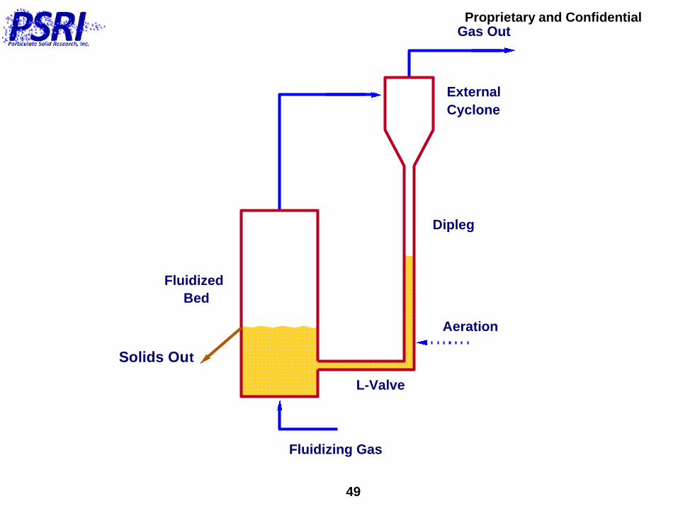
49
Aeration
Dipleg
Gas Out
External
Cyclone
L-Valve
Fluidizing Gas
Fluidized
Bed
Solids Out
Proprietary and Confidential
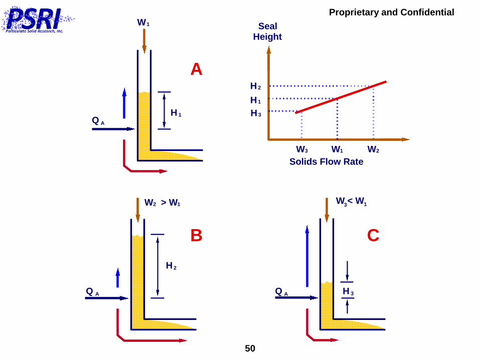
50
W W W
Solids Flow Rate
W
QH 1
1
A
W > W12 W < W 13
H 2
Q A Q A H 3
SealHeight
1 23
H 1
H 2
H 3
A
B C

Proprietary and Confidential
51
Chemical Looping Systems
In the Following Slides, Several Different Types of
Proposed Solids Flow Systems for Chemical Looping
are Shown
The Techniques Used to Control the Solids Flow Rate
Around Each of the Systems Are Different

Proprietary and Confidential
52
CONTROL OF NONMECHANICAL
SYSTEMS
There are Four Ways to Control the Solids Flow Rate
in Nonmechanical Systems:
1. Using a Nonmechanical L-Valve Below a Packed
Bed Standpipe
2. Operating the Riser at the Choking Velocity to
Control the Solids Flow Rate
3. Using Inventory Control to Change the Level in an
Overflow Fluidized Bed Standpipe
4. A Combination of Methods 2 and 3

Proprietary and Confidential
53
AerationAeration
L-ValveL-Valve
Riser 2 GasRiser 1 Gas
Fluid Bed 2
Loop
SealLoop
SealFluid Bed 1
CycloneCyclone
L-Valve
Control
System
Yazdanpanah et. al., CFB-10
Proc., May 2-5, 2011
dp = 320 microns
Advantage(s):
1. Good Solids Flow
Control
2. Do Not Need to
Change Inventory
for Control
Disadvantage(s):
1. Works With B/D
Geldart Groups
Only
Conclusion:
Good, Solid Design
Proprietary and Confidential
54
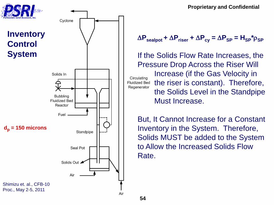
Inventory
Control
System
Shimizu et. al., CFB-10
Proc., May 2-5, 2011
dp = 150 microns
DPsealpot + DPriser + DPcy = DPSP = HSP*SP
If the Solids Flow Rate Increases, the
Pressure Drop Across the Riser Will
Increase (if the Gas Velocity in
the riser is constant). Therefore,
the Solids Level in the Standpipe
Must Increase.
But, It Cannot Increase for a Constant
Inventory in the System. Therefore,
Solids MUST be added to the System
to Allow the Increased Solids Flow
Rate.
Proprietary and Confidential
55
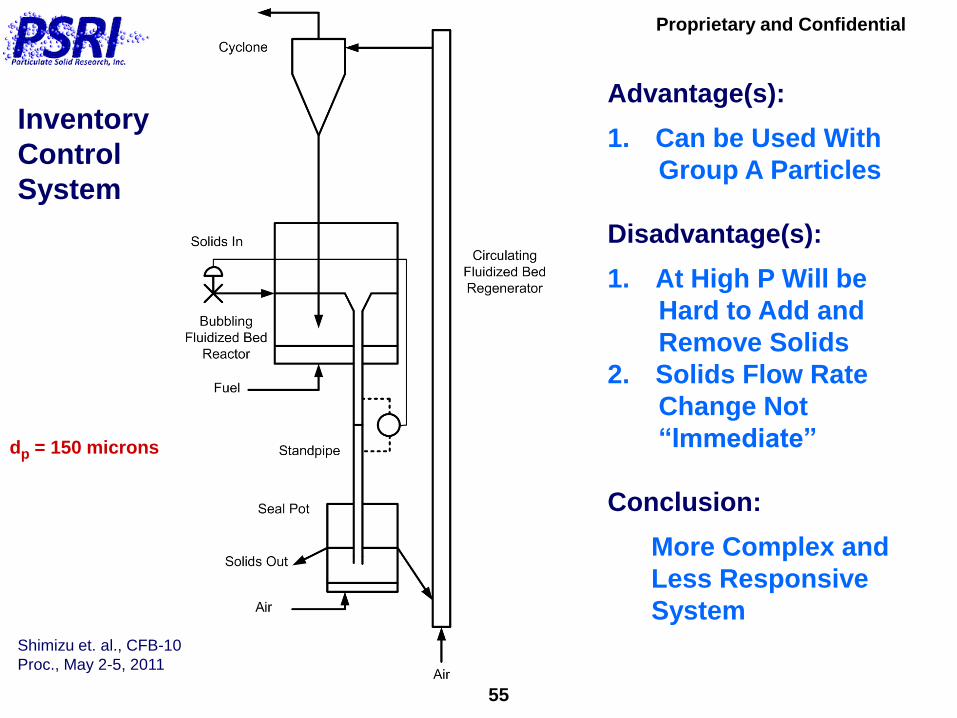
Inventory
Control
System
Shimizu et. al., CFB-10
Proc., May 2-5, 2011
dp = 150 microns
Advantage(s):
1. Can be Used With
Group A Particles
Disadvantage(s):
1. At High P Will be
Hard to Add and
Remove Solids
2. Solids Flow Rate
Change Not
“Immediate”
Conclusion:
More Complex and
Less Responsive
System

Proprietary and Confidential
56
Inventory +
Riser Control
System
Guio-Perez et. al., CFB-10
Proc., May 2-5, 2011
Loop
Seal
3
Loop
Seal
1
Cyclone 2
Cyclone 1
Aeration
Control
Air
Riser
Loop
Seal
2
Aeration
Aeration
Fuel
Air
dp = 161 microns
Advantage(s):
1. Can be Used With
Group A Particles
Disadvantage(s):
1. At High P Will be
Hard to Add and
Remove Solids
2. Solids Flow Rate
Change Not
“Immediate”
Conclusion:
More Complex and
Less Responsive
System
Proprietary and Confidential
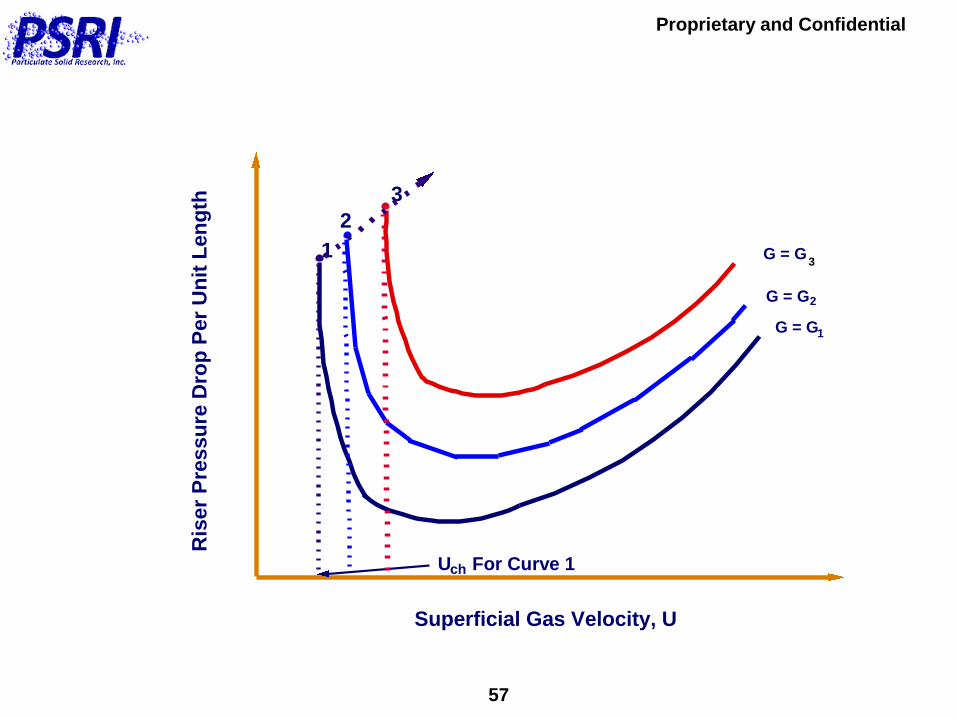
57
Superficial Gas Velocity, U
Ris
er
Pre
ssu
re D
rop
Per
Un
it L
en
gth
G = G1
2
U For Curve 1ch
2
G = G1
3
G = G
3

Proprietary and Confidential
58
L-Valve
Control
The Ohio State University,
L.S. Fan and Colleagues
Advantage(s):
1. Good Solids Flow
Control
2. Do Not Need to
Change Inventory
for Control
Disadvantage(s):
1. Cannot be Used
With Group A
Solids
Conclusion:
Good, Solid Design
Large Group B and
Group D Particles

Proprietary and Confidential
59
Riser
Control
Chalmers Univ. of Tech.,
A. Lyngfeldt, 1st Intl Conf
on Chem Looping, Lyon
March 17-19, 2010
Advantage(s):
1. Can be Used With
Group A Particles
Disadvantage(s):
1. At High P Will be
Hard to Add and
Remove Solids
2. Solids Flow Rate
Change Not
“Immediate”
Conclusion:
Less Responsive
System
Varied

Proprietary and Confidential
60
Thank You!
Questions?