nor me cei internationale iec international … · copyright by the international electrotechnical...
TRANSCRIPT

Copyright by the International Electrotechnical CommissionThu Jan 06 00:32:30 2011
IEC 1024 PT*1 90 .. 4844891 0101094 8 ..
NOR ME INTERNATIONALE INTERNATIONAL STANDARD
CEI IEC
1024-1 Premiere edition
First edition 1990-03
Protection des structures contre Ia foudre
Premiere partie: Principes g€meraux
Protection of structures against lightning
Part 1: General principles
Numero de reference Reference number
CE!(!EC 1024-1: 1990

Copyright by the International Electrotechnical CommissionThu Jan 06 00:32:34 2011
IEC 1024 PT*1 90 II 4844891 0101095 T II
Revision de Ia presente publication
Le contenu technique des publications de Ia CE I est constamment revu par Ia Commission afin d'assurer qu'il reflete bien J'etat actuel de Ia technique.
Les renseignements relatifs a ce travail de revision, a l'etablissement des editions revisees et aux mises a jour peuvent etre obtenus au pres des Comites nationaux de Ia CE I et en consultant les documents ci-dessous:
e Bulletin de Ia C E I
e Annuaire de Ia C E I
e Catalogue des publications de Ia C E I
Publie annuellement
Terminologie
En ce qui concerne Ia terminologie generale, le lecteur se reportera a Ia Publication 50 de Ia C E I: Vocabulaire Electrotechnique International (VEl), qui est etablie sous forme de chapitres separes traitant chacun d'un sujet defini, !'Index general etant publie separement. Des details complets sur leVEl peuvent etre obtenus sur demande.
Les termes et definitions figurant dans Ia presente publication ont ete so it repris du VEl, so it specifiquement approuves aux fins de cette publication.
Symboles graphiques et Iitteraux
Pour les symboles graphiques, symboles litteraux et signes d'usage general approuves par Ia C E I, le lecteur consultera:
Ia Publication 27 de Ia C E I: Symboles litteraux a utiliser en electrotechnique;
Ia Publication 617 de Ia C E I: Symboles graphiques pour schemas.
Les symboles et signes con tenus dans Ia pres'ente publication ont ete soit repris des Publications 27 ou 617 de Ia CEI, soit specifiquement approuves aux fins de cettc publication.
Publications de Ia CEI etablies par le meme Comite d'Etudes
L'attention du lecteur est attiree sur le deuxieme feuillet de Ia couverture, qui enumere les publications de Ia CE I preparees par le Comite d'Etudes qui a etabli Ia presente publication.
Revision of this publication
The technical content of I EC publications is kept under constant review by the I EC, thus ensuring that the content reflects current technology.
Information on the work of revision, the issue of revised editions and amendment sheets may be obtained from I EC National Committees and from the following IE C sources:
e I EC Bulletin
e I EC Yearbook
e Catalogue of I EC Publications
Published yearly
Terminology
For general terminology, readers are referred to I EC Publication 50: International Electrotechnical Vocabulary (lEV}, which is issued in the form of separate chapters each dealing with a specific field, the General Index being published as a separate booklet. Full details of the IEV will be supplied on request.
The terms and definitions contained in the present publication have either been taken from the lEV or have been specifically approved for the purpose of this publication.
Graphical and letter symbols
For graphical symbols, and letter symbols and signs approved by the I E C for general use, readers are referred to:
I EC Publication 27: Letter symbols to be used in electrical technology;
IEC Publication 617~ Graphical symbols for diagrams.
The symbols and signs contained in the present publication have either been taken from I EC Publications 27 or 617, or have been specifically approved for the purpose of this publication.
IEC publications prepared by the same Technical Committee
The attention of readers is drawn to the back cover, which lists I EC publications issued by the Technical Committee which has prepared the present publication.
Daneshkaran (Mobile Library) Tel:+9821-22967252 & 22989530 Fax:+9821-22957146 Mobile: 09126939613 www.Daneshkaran.ir

Copyright by the International Electrotechnical CommissionThu Jan 06 00:32:35 2011
IEC 1024 PT*1 90 II 4844891 0101096 1 II
NORME INTERNATIONALE INTERNATIONAL STANDARD
CEI IEC
1024-1 Premiere edition
First ·edition 1990-03
Protection des structures contre Ia foudre
Premiere partie: _ Principes generaux
Protection of structures against lightning
Part 1: General principles
© C E I 1990 Droits de reproduction reserves - Copyright - all rights reserved
Aucune partie de cette publication ne peut olre reproduke ni uti Iisee sous quelque forme que ce soil et par aucun procede, electronique ou mecanique, y compris Ia photocopie et les micrpfilms, sans !'accord ecr!t de !'Bditeur.
No part of this publication may be reproduced or utilized in any form or by any means, electronic or mechanical, including photocopying and microfilm, without permission in writing from the publisher.
Bureau Central de Ia Commission Electrotechnique lnternationale
Commission Eiectrotechnique Internationals
International Electrotechnical Commission
MeHi,llyHapo.nHaH 3JleKtporexHH4ecHa~ HoMHCOHA
3, rue de Varembe Geneve, Suisse
CODE PRIX PRICE CODE T .Pour prix, voir catalogue en vigueur For price, see current catalogue

Copyright by the International Electrotechnical CommissionThu Jan 06 00:32:35 2011
PREAMBULE.
PREFACE ..
INTRODUCTION
Articles
IEC 1024 PT*1 90 .. 4844891 0101097 3 ..
- 2-
SOMMAIRE
1024-1 © CEI
Pages
4
4
6
1. Generalites . . . . . . . . . . . . . . 8 1.1 Domaine d'application et objet 8 1.2 Termes et definitions . . . . . 8 1.3 Structures en beton arme . . . 14
2. Installation exterieure de protection contre la foudre 14 2.1· Dispositifs de capture . . 14 2.2 Conducteurs de descente 18 2.3 Prises de terre . . . . . . 22 2.4 Fixation et raccords . . . 26 2. 5 Materiaux et dimensions 26
3. Installation interieure de protection contre la foudre . . 28 3.1 Liaison equipotentielle . . . . . . . . . . . . . . . . 28 3.2 Proximite des installations de protection contre la foudre et d'autres installations 32 3.3 Protection contre 1e risque de choc electrique . . . . . . . . . . . . . . . . . . . 32
4. Conception, entretien et verification des installations de prot.ection contre la foudre 32 4.1 Conception . . . . . . . 32 4.2 Entretien et veri,fication 34
TABLEAUX
FIGURES .
36
42
Daneshkaran (Mobile Library) Tel:+9821-22967252 & 22989530 Fax:+9821-22957146 Mobile: 09126939613 www.Daneshkaran.ir

Copyright by the International Electrotechnical CommissionThu Jan 06 00:32:35 2011
IEC 1024 PT*1 90 .. 4844891 0101098 5 ..
1024-1 © IEC - 3 -
CONTENTS
FOREWORD
PREFACE •
INTRODUCTION
Clause
1. General .......... . 1.1 Scope and object . . . 1.2 Terms and definitions 1.3 Reinforced concrete structures . .
2. External lightning protection system (LPS) 2.1 Air termination systems . . 2.2 Down-conductor systems 2.3 Earth termination systems 2.4 Clamping and joints . . . . 2.5 Materials and dimensions
3. Internal lightning protection system 3.1 Equipotential bonding ..... 3.2 Proximity of installations to LPS 3.3 Safeguard against life hazard . . .
4. Design, maintenance and inspection of LPS 4.1 Design ............. . 4.2 Maintenance and inspection
TABLES
FIGURES
Page
5
5
7
9 9 9
is
15 15 19 23 27 27
29 29 33 33
33 33 35
37
43
Copyright by the International Electrotechnical CommissionThu Jan 06 00:32:35 2011
IEC 1024 PT*1 90 II 4844891 0101099 7 II
- 4- 1024-1 © CEI
COMMISSION ELECTROTECHNIQUE INTERNATIONALE
PROTECTION DES STRUCTURES CONTRE LA FOUDRE
Premiere partie: Principes generaux
PREAMBULE
1) Les decisions ou accords officiels de Ia C EI en ce qui concerne les questions techniques, prepares par des Comites d'Etudes ou sont representes tousles Comites nationaux s'interessant aces questions, expriment dans Ia plus grande mesure possible un accord international sur les sujet~ examines. ·
2) Ces decisions constituent des recommandations internationales et sont agreees comme telles par les Comites nationaux.
3) Dans le but d'encourager !'unification internationale, Ia CEI exprime le vreu que tous les Comites nationaux adoptent dans leurs regles nationales le texte de la recommandation de Ia CEI dans Ia mesure ou les conditions nationales le permettent. Toute divergence entre la recommandation de la CEI et Ia regie nationale correspondante doit, dans Ia mesure du possible, etre indiquee en termes clairs dans cette demiere.
PREFACE
La presente norme a ete etablie par le Comite d'Etudes n° 81 de la CEI: Protection contre la foudre.
Elle.constitue la premiere partie de la serie traitant de la protection des bil.timents contre la foudre.
Le texte ·de la presente norme est issu des documents suivants:
Regie des Six Mois Rapport de vote Procedure des Deux Mois Rapports de vote
81(BC)6 81(BC)8 81(BC)9 81(BC)10 et 10 A 81(BC)11 81(BC)12
Les rapports de vote indiques dans le tableau ci-dessus domient toute information sur le vote ayant abouti a !'approbation de cette norme. .
Les publications suivantes de Ia CEI sont citees dans Ia presente norme:
Publications nos 50 (826) (1982): Vocabulaire Electrotechhique International (VEl), Chapitre 826: Installations electriques des biitiments. ·
364-4-41 (1982): Installations electriques des biitiments, Quatrieme partie: Protection pour assurer la seenrite - Chapitre 41: Protection contre 1es chocs elec~riques.
Daneshkaran (Mobile Library) Tel:+9821-22967252 & 22989530 Fax:+9821-22957146 Mobile: 09126939613 www.Daneshkaran.ir
Copyright by the International Electrotechnical CommissionThu Jan 06 00:32:35 2011
1-•
IEC 1024 PT*1 90 .. 4844891 0101100 T ..
1024-1 © IEC - 5 -
INTERNATIONAL ELECTROTECHNICAL COMMISSION
PROTECTION OF STRUCTURES AGAINST LIGHTNING
Part 1 : General principles
FOREWORD
1) The formal decisions or agreements of the IEC on technical matters, prepared by Technical Committees on which all the National.Committees having a special interest therein are represented, express, as nearly as possible, an international consensus of opinion on the subjects dealt with. ·
2) They have the form of recommendations for international use and they are accepted by the National Committees in that sense.
3) In order to promote international unification, the IEC expresses the wish that all National Committees should adopt the text · of the IEC recommendation for their national rules in so far a~national conditions will permit. Any divergence between the IEC recommendation and the corresponding national rules should, as far as possible, be clearly indicated in the latter.
PREFACE
This standard has been prepared by IEC Technical Committee 81: Lightning protection.
It forms Part 1 of a series dealing with the protection of structures against lightning.
The text of this standard is based on the following documents:
Six Months' Rule Report on Voting Two Months' Procedure· Report on Voting
e
81(C0)6 81(C0)8 81{C0)9. 81(C0)10 and lOA 81(CO)ll 8l(C0)12·
Full information on the voting for the approval of this standard can be found in the Voting Reports indicated in the above table.
The following IEC publications are quoted in this standard:
Publications Nos. 50(826) (1982): International Electrotechnical Vocabulary {lEV), Chapter 826: Electrical installations of buildings. ·
364-4-41 (1982): Electrical installations of buildings, Part 4: Protection for safety- Chapter 41: Protection against electric shock.
Copyright by the International Electrotechnical CommissionThu Jan 06 00:32:36 2011
IEC 1024 PT*1 90 II 4844891 0101101 1 11
- 6- 1024-1 © CEI
PROTECTION DES STRUCTURES CONTRE LA FOUDRE
Premiere partie: Principes generaux
INTRODUCTION
II ne faut pas oublier qu'une installation de protectron contre l!J. foudre ne peut empecher la formation des eclairs.
Une installation de protection_ contre la foudre, concue et installee conformement a la presente norme, ne peut assurer la protection absolue des structures·, des personnes ou des objets; neanmoins, !'application de la presente norme doit reduire de facon significative les risques de degats dus a la foudre sur les structures protegees conformement a cette norme.
Le type et !'emplacement de !'installation de protection contre la foudre doivent etre etudies avec so in des le stade de la conception d'une nouvelle structure, afin de pouvoir tirer un parti maximal des elements conducteurs de ce demier. Cela facilitera l'etude et la realisation d'une installation integree, permettra d'en ameliorer l'aspect esthetique, d'accroltre l'efficacite de l'installatiori de protection et d'en minimiser le cout et le travail de realisation.
L'acces ala terre et une utilisation appropriee des armatures de fondation pour la realisation d'une prise de terre appropriee risquent de ne plus etre possibles a pres le debut des travaux de construction. II convient que la resistivite et la nature du sol soient prises en compte aussi tot que possible des le stade initial du projet. Ces informations sont essentielles pour l'etude des prises de terre, qui peuvent influencer les travaux de conception des fondations effectues par les architectes.
Pour eviter to us travaux inutiles, il est primordial que les concepteurs de !'installation de protection contre la foudre, les architectes et les entrepreneurs se consultent regulierement.
La presente norme fournit des informations relatives a la realisation d'installations de protection contre la foudre, destinees aux structures habituelles.
Des normes a publier ulterieurement fourniront des informations complementaires pour la protection contre la foudre de structures non habituelles, telles que:
- structures tres elevees;
- structures avec risque de panique;
- structures avec risque d'incendie ou d'explosion.
D'autres publications traitero:t?-t d'aspects particuliers relevant de la protection des equipements electriques et electroniques contre les perturbations dues a la foudre.
En outre, des guides d'application aideront les utilisateurs dans I' evaluation du risque, le choix d'un niveau de protection approprie et la realisation des installations.
II y a lieu que la conception, !'installation et les materiaux des installations satisfassent entierement aux dispositions de la presente norme.
Daneshkaran (Mobile Library) Tel:+9821-22967252 & 22989530 Fax:+9821-22957146 Mobile: 09126939613 www.Daneshkaran.ir

Copyright by the International Electrotechnical CommissionThu Jan 06 00:32:36 2011
IEC 1024 PT*1 90 II 4844891 0101102 3 II
1024-1 © IEC - 7 -
PROTECTION OF STRUCTURES AGAINST LIGHTNING
Part 1 : General principles
INTRODUCfiON
It should be noted that a lightning protection system cannot prevent the formation of lightning.
A lightning protection system, designed and installed in accordance with this standard, cannot guarantee absolute protection to structures, persons, or objects; however, application of this standard will significantly reduce risk of damage caused by lightning to the structure protected by it.
The type and location of a lightning protection system should be carefully considered at the design stage of a new structure, thereby enabling maximum advantage to be taken of the electrically conductive parts of the structure. Thus design and construction of an integrated installation is made easier, the overall aesthetic aspects can be improved, and the effectiveness of the lightning protection system can be increased at minimum cost and effort.
Access to ground and proper use of foundation steelwork for the purpose of forming an effective earth termination may well be impossible once construction work on a site has commenced. Therefore, soil resistivity and the nature of the earth should be considered at the earliest possible stage of a project. This information is fundamental to the design of an earth termination system which may influence the foundation design work of architects.
To avoid unnecessary work, regular consultation between lightning protection system designers, architects and builders is essential.
This standard provides information on setting up Lightning Protection Systems (LPS) for common structures.
Future standards will. provide additional information on lightning protection for non-common structures, such as:
- tall structures;
- structures with risk of panic;
- structures with risk of fire or explosion.
Other publications will cover particular aspects related to protection of elec~ric and electronic equipment against lightning interference.
Moreover, application guides will assist users in the assessment of the risk, in the selection of the appropriate protection level and in the construction of LPSs.
The design, installation and materials of LPS should fully comply with the provisions of this standard.

Copyright by the International Electrotechnical CommissionThu Jan 06 00:32:36 2011
IEC 1024 PT*1 90 II 4844891 0101103 5 II
- 8 - 1024-1 © CEI
1. Generalites
1.1 Domaine d'application et objet
1.1.1 Domaine d'app!icqtion
La presente norme est applicable a la conception et a la realisation des installations de protection contre la foudre, destinees aux structures habituelles dont la hauteur n'est pas superieure a 60 m.
Les cas suivants sont hors du domaine d'application de cette norme:
a) chemins de fer;
b) reseaux de production, transport d'energie et distribution d'e1ectricite exterieurs a une structure;
c) installations de telecommunications cxterieures a une structure;
d) vehicules, navires, aeronefs et installations en mer.
Note. - Les installations citees aux points a) a d) sont habituellement soumiscs a des reglementations speciales edictees par differentes autorites competentes.
1.1.2 Objet
La presente norme fournit des informations relatives a la conception, la realisation, la verification et l'entretien d'installations efficaces de protection contre la foudre des structures definis au paragraphe 1.1.1, ainsi que des personnes, des installations et des objets qu'ils contiennent.
1.2 Termes et definitions
Les definitions suivantes sont applicables dans le cadre de la presente norme.
1.2.1 Foudre ou eclair a Ia terre
Decharge electrique d'origine atmospherique entre un nuage et la terre, consistant en un ou plusieurs coups de foudre.
1.2.2 Coup de joudre
L'une des decharges electriques lors d'un eclair a ~a terre.
1.2.3 Point d'impact
Point ou un coup de foudre frappe la terre, une structure ou une installation de protection contre la foudre.
Note. - Un eclair peut avoir plusieurs points d'impact.
1.2.4 Espace a proteger
Espace d~une structure ou d'une zone, pour lequel une protection contre les effets de la foudre, conforme a la presente norme, est envisagee.
Daneshkaran (Mobile Library) Tel:+9821-22967252 & 22989530 Fax:+9821-22957146 Mobile: 09126939613 www.Daneshkaran.ir
Copyright by the International Electrotechnical CommissionThu Jan 06 00:32:36 2011
IEC 1024 PT*1 90 .. 4844891 0101104 7 ..
1024-1 © IEC - 9 -
I. General
1.1 Scope and object
1.1.1 Scope
This standard is applicable to the design and installation of Lightning Protection Systems (LPS) for common structures up to 60 m high.
The following cases are outside the scope of this standard:
a) railway systems;
b) electrical transmission, distribution and generating systems external to a structure;
c) telecommunication systems external to a structure;
d) vehicles, ships, aircraft, offshore installations.
Note. - Usually the systems from a) to d) are under special regulations made by various specific authorities.
1.1.2 Object
This standard provides information for the design, installation, inspection and maintenance of an effective system for the protection of structures against lightning as indicated in Subclause 1.1.1, as well as for persons, installations and contents in or on them.
1.2 Terms and definitions
For the purpose of this standard, the following definitions apply.
1.2.1 Lightning flash to earth
An electrical discharge of atmospheric origin between cloud and earth consisting of one or more strokes.
1.2.2 Lightning stroke
A single electrical discharge in a lightning flash to earth.
1.2.3 Point of strike
A point where a lightning stroke c~mtacts the earth, a structure or an LPS.
Note. - A flash may have more than one point of strike.
1.2.4 Space to be protected
The part of a structure or region for which protection against the effects of lightning in accordance with this standard is required.

Copyright by the International Electrotechnical CommissionThu Jan 06 00:32:36 2011
IEC 1024 PT*1 90 II 4844891 0101105 9 II
-10- 1024-1 © CEI
1.2.5 Installation de protection contre lafoudre
Installation complete, permettant de prot~ger une structure contre les effets de la foudre. Elle comprend ala fois une installation exterieure et une installation interieure de protection contre la foudre.
Note. - Dans des cas particuliers, !'installation de protection contre la foudre peut consister en une installation exterieure ou une installation interieure seulement.
1.2. 6 Installqtion · exterieure de protection contre fa foudre
Cette installation comprend un dispositif de capture, des conducteurs de descente et une prise de terre.
1.2. 7 Installation interieure de protection contre fa foudre.
Cette installation comprend tousles dispositifs complementaires au paragraphe 1.2.6, reduisant les effets electromagnetiques du courant de decharge atmospherique a l'interieur de l'espace a proteger. . .
1.2.8 Liaison equipotentielle
Elements d'une installation interieurereduisant les differences de potentiel engendrees par le courant de decharge atmospherique.
1.2. 9 Dispositif de capture
Partie de !'installation exterieure destinee a intercepter les eclairs.
1.2.1 0 Conducteur de descente
Partie de !'installation exterieure destinee a conduire le· courant de decharge atmospherique du dispositif de capture a la prise de terre.
1.2.11 Prise de terre
Partie de !'installation exterieure destinee a conduire et a dissiper le courant de· decharge at~ospherique a la terre.
Note. - Dans les sols de resistivite elevee, la prise de terre peut intercepter les courants de foudre s'.ecoulant dans le sol et provenant d'eclairs a .Ia terre tombes a proximite.
1 .2. 12 Electrode de terre
Element ou ensemble d'elements de la prise de terre assurant un contact electrique direct avec la terre et dissipant le courant de decharge atmospherique dans cette derniere.
1 .2.13 Electrode de terre en boucle
Electrode de terre constituee d'une electrode formant une boucie fermee au tour de la structure, au-dessous ou sur la surface du sol.
1 :2.14 Electrode de terre en fond de fouille
Electrode de terre noyee dans les fondations en beton de la structure.
Daneshkaran (Mobile Library) Tel:+9821-22967252 & 22989530 Fax:+9821-22957146 Mobile: 09126939613 www.Daneshkaran.ir

Copyright by the International Electrotechnical CommissionThu Jan 06 00:32:37 2011
IEC 1024 PT*1 90 .. 4844891 0101106 0 ..
1024-1 © IEC - 11 -
1.2.5 Lightning protection system (LPS)
The complete system used to protect a space against the effects oflightning. It consists of both external and internal lightning protection systems.
Note. - In particular cases, an LPS may consist of an external LPS or an internal LPS only.
f.2.6 External lightning protection system
This system consists of an air-termination system, a down-conductor system and an earthtermination system.
1.2. 7 InternallightniTJ.g protection system
All measures additional to those given in Sub-clause 1.2.6 which would reduce the electromagnetic effects of lightning current within the space to be protected.
1.2.8 Equipotential bonding (EB)
That part of an internal LPS which reduces potential differences caused by lightning current.
1.2.9 Air-termination system
That part of an external LPS which is intended to intercept lightning flashes.
1.2.1 0 Down-conductor
That part of an external LPS which is intended to conduct lightning current from the airtermination system to the earth-termination system.
1.2.11 Earth-termination system
That part of an external LPS which is intended to conduct and disperse lightning current to the earth.
Note. - In high resistivity soils the earth-termination system may intercept lightning currents flowing through the soil due to lightning flashes to the earth in the neighbourhood.
1.2.12 Earth electrode
A part or group of parts of the earth-termination system which provides direct electrical contact with and disperses the lightning current to the earth.
1.2.13 Ring earth electrode
An earth electrode forming a closed loop around the structure belo\v or on the surface of the earth.
1.2.14 Foundation earth electrode
An earth electrode embedded in the concrete foundation of a structure.
Copyright by the International Electrotechnical CommissionThu Jan 06 00:32:37 2011
IEC 1024 PT*1 90 II 4844891 0101107 2 II
- 12 - 1024-1 © CEI
L2. 15 Resistance de terre equivalente
Rapport entre les valeurs de crete de la tension et du courant dans la prise de terre qui, en general, n'apparaissent pas simultanement; i1 est utilise conventionnellement pour caracteriser l'efficacite de la prise de terre.
1 .2.16 Potentiel de la prise de terre
Difference de potentiel entre la prise de terre et 1a terre.
1.2.17 Composant «nature!» de !'installation de protection contre la foudre
Composant assurant une fonction de protection contre la foudre, mais non installe specifiquement a cet effet.
Note. - Des exemples· d'utilisation de ce terme sont:
- capteur «nature!»;
- descente «naturelle»;
- electrode de terre «naturelle».
1.2. 18 Equipements metalliques
Element~ metalliques repartis dans l'espace a proteger, pouvant ecouler une partie du courant de decharge atmosph6rique tels que canalisations, escaliers, guides d'ascenseur, conduits de ventilation, de chauffage et d'air conditionne, armatures d'acier interconnectees.
1.2.19 Barre d'equipotentialite
Barre permettant de relier a.· !'installation de protection contre la foudre les equipements metalliques, les masses, les lignes electriques et de telecommunication et d'autres cables.
1 .2.20 Conducteur d'equipotentialite
Conducteur permettant d'assurer l'equipotentialite.
1.2.21 Armatures d'acier interconnectees
Armatures d'acier a l'interie_~r d'une structure, considerees comme assurant une continuite electrique. .
1.2.22 Etincelle dangereuse
Decharge electrique inadmissible, provoquee par le courant de decharge atmospherique a l'interieur du volume a proteger.
1.2.23 Distance de securite
Distance minimale entre deux elements conducteurs a l'interieur de l'espace a proteger, telle qu'aucune etincelle dangereuse ne puisse se produire entre eux. --
1.2.24 _ Parasurtension
Dispositif destine a limiter les surtensions entre deux elements a l'interieur de l'espace a proteger, tels qu'eclateurs, parafoudres 'ou dispositifs' a semiconducteurs.
Daneshkaran (Mobile Library) Tel:+9821-22967252 & 22989530 Fax:+9821-22957146 Mobile: 09126939613 www.Daneshkaran.ir
Copyright by the International Electrotechnical CommissionThu Jan 06 00:32:37 2011
IEC 1024 PT*1 90 II 4844891 0101108 4 II
1024-1 © IEC - 13 -
1.2.15 Equivalent earth resistance
The ratio of the peak values qfthe earth-termination voltage and the earth-termination current which, in general, do not occur simultaneously. It is used conventionally to indicate the efficiency of the earth-termination system.
1.2.16 Earth-termination voltage
The potential difference between an earth-termination system and the earth.
1.2.17 "Natural" component of an LPS
A component which performs a lightning protection function but is not installed specifically for that purpose.
Note. - Some examples of the use of this term are as follows:
- "natural" air-termination;
- "natural" down-conductor;
- "natural" earth electrode.
1.2.18 Metal installations
Extended metal items in the space to be protected which may form a path for lightning current, such as pipe-work, staircases, elevator guide rails, ventilation, heating and air conditioning ducts, and interconnected reinforcing steel.
1.2.19 Bonding bar
A bar on which metal installations, extraneous conductive parts, electrical power and. telecommunication lines, and other cables can be bonded to an LPS.
1.2.20 Bonding conductor
Conductor for equalization of potentials.
1.2.21 Interconnected reinforcing steel
Steelwork within a structure which is considered to be electrically continuous.
1.2.22 Dangerous sparking
An unacceptable electrical discharge caused by lightning current inside the space to be protected.
1.2.23 Safety distance
The minimum distance between two conductive parts within the space to be protected between which no dangerous sparking can occur.
A device designed to limit the surge voltage between two parts within the space to be protected, such as spark gap, surge diverter or semiconductor device.

Copyright by the International Electrotechnical CommissionThu Jan 06 00:32:37 2011
IEC 1024 PT*1 90 II 4844891 0101109 b II
- 14 - 1024-1 © CEI
1.2.25 Borne d'essai -
Dispositif conr;:u et place de manU~re a faciliter les essais et mesures electriques des elements de !'installation de protection contre la foudre.
1.2.26 Installation exterieure isotee du volume a proteger
Installation dont le dispositif de capture et les descentes sont places de manii~re que le trajet du courant de decharge atmospherique n'ait aucun contact avec l'espace a proteger.
1.2.27 Installation exterieure non isolee du volume a proteger
Installation dont le dispositif de capture et les descentes sont places de maniere que le trajet du courant de decharge atmospherique soit en contact avec l'espace a proteger.
1.2.28 Structures habituelles
Structures utilisees a des fins commerciales, industrielles, agricoles, administratives ou residentielles.
1.2.29 Niveau de protection
Terme de classification d'une installation de protection contre la foudre exprimant son efficacite.
Note. - Ce terme exprime Ia probabilite avec laquelle une installation protege un espace contre Ia foudre.
1.3 Structures en beton arme
Les armatures metalliques des structures en beton arme sont considerees comme assurant une continuite electrique lorsqu'elles satisfont aux conditions suivantes: · ·
a) environ 50% des interconnexions de barres verticales et horizontales sont soudees ou solidement liees;
b) les barres verticales sont soudees ou se chevauchent sur 20 fois leur diametre au moins et sont solidement reunies;
c) la continuite electrique est assuree entre les armatures d'acier des differents elements prefabriques en beton et celles des elements en beton prefabriques voisins.
2. Installation exterieure de protection· contre Ia foudre
2.1 Dispositifs de capture
2.1.1 Generalites
La probabilite de penetration d'un coup de foudre dans l'espace a proteger est considerablement reduite par la presence d'un dispositif de capture convenablement conr;:u.
Les dispositifs de capture peuvent etre constitues par une combinaison quelconque des com-posants suivants:
1) tiges;
2). fils tend us;
3) conducteurs mailles.
Daneshkaran (Mobile Library) Tel:+9821-22967252 & 22989530 Fax:+9821-22957146 Mobile: 09126939613 www.Daneshkaran.ir

Copyright by the International Electrotechnical CommissionThu Jan 06 00:32:38 2011
~IEC 1024 PT*1 90 .. 4844891 0101110 2 ..
1024-1 © IEC - 15 -
1.2.25 Test joint
A joint which is designed and situated to facilitate electrical testing and measurement of LPS components.
1.2.26 External LPS isolated from the space to be protected
·An LPS whose air-termination system and down-conductor system are positioned in such a way that the path of the lightning current has no contact with the space to be protected.
1.2.27 External LPS not isolated from the space to be protected
An LPS whose air-termination system and down-conductor system are positioned in such a way that the path of the lightning current can be in contact with the space to be protected.
1.2.28 Common structures
Common structures are structures used for ordinary purposes whether commercial, industrial, farm, institutional or residential.
1.2.29 . Protection level
A term denoting the classification of an LPS according to its efficiency,
Note. - It expresses the probability with which an LPS protects a space against the effects of lightning.
1.3 Reinforced concrete structures
Steelwork within reinforced concrete structures is considered to be electricaliy continuous provided that it fulfils the following conditions:
a) approximately 50% of interconnections of vertical and horizontal bars are welded or are securely tied;
b) vertical bars are welded or are overlapped a minimum of 20 times their diameters and securely tied;
c) electrical continuity of the reinforcing steel is established between ~dividual precast concrete units and other adjacent precast concrete units.
2. External lightning protection system (LPS)
2.1 Air-termination systems
2.1.1 General
The probability of a lightning stroke penetrating the space to be protected is considerably decreased by the presence of a properly designed air-termination system.
The air-termination systems can be composed of any combination of the following elements:
1) rods;
2) stretched wires;
3) meshed conductors.

Copyright by the International Electrotechnical CommissionThu Jan 06 00:32:38 2011
IEC 1024 PT*1 90 II 4844891 0101111 4 II
- 16 - 1024-1 © CEI
2.1.2 Positionnement
Un dispositif de capture est correctement mis en place s'il satisfait aux prescriptions du tableau 1. Pour l'etude du dispositif de capture, les methodes suivantes peuvent etre utilisees, separ~ment ou combinees d'une manif~re quelconque:
a) angle de protection;
b) sphere fictive;
c) _ maillage.
Note. - Les informations sur ces methodes de conception et sur les relations existant entre le positionnement des dispositifs de capture et les niveaux de protection seront donnees dans le Guide B, traitant de Ia construction des systemes de protection contre Ia foudre, qui fera !'objet d'une future publication de Ia CEI. ·
2.1.3 Construction
Pour une installation isolee, la distance entre le dispositif de capture et l'equipement metallique de l'espace a proteger doit etre superieure a Ia distance de securite definie au paragraphe 3.2.
Pour une installation non isolee de I' espace a proteger, le dispositif de capture peut etre installe directement sur le toit ou a une faible distance, a condition que le courant de decharge atmospherique ne provoque aucun dommage.
Pour la determination de l'espace protege contre les coups de foudre, on ne prendra en consideration que les dimensions reelles du dispositif de capture.
2.1.4 Composants «nature Is»
Les parties suivantes de structures peuvent etre considerees comme dispositifs de capture «naturelS)):
a) lestales metalliques recouvrant l'espace a proteger, sous reserve que:
..:. la continuite electrique entre les differentes parties soit realisee de fayon durable;
- l'epaisseur des tales metalliques ne soit pas inferieure ala valeur t figurant dans le tableau 2, s'il s'avere necessaire de les prot6ger contre les perforations ou s'il existe des problemes de points chauds;
- l'epaisseur des tales metalliques ne so it pas inferieure a 0,5 mm, s'il n'est pas essen tiel de les .proteger contre les perforations et s'il n'y a pas de risque d'inflammation de materiaux combustibles situes au-dessous;
- elles ne soient pas revetues de materiau isolant;
- les materiaux non metalliques sur ou au-dessus des tales metalliques soient exclus de l'espace a proteger;
b) les elements metalliques de construction du toit (fermes, armatures d'acier interconnectees, etc.) reconverts de materiaux non metalliques, a condition que ces derniers puissent etre exclus de l'espace a proteger;
c) les pieces metalliques dutype gouttieres, decorations, rambardes, etc., dont la section n'est pas inferieure a celle qui est specifiee pour 1es composants normaux du dispositif de capture;
d) les tuyaux et reservoirs metalliques, s'ils sont realises en un materiau d'au mains 2,5 mm d'epaisseur et si leur perforation n'entraine pas de situation dangereuse ou inacceptable;
Daneshkaran (Mobile Library) Tel:+9821-22967252 & 22989530 Fax:+9821-22957146 Mobile: 09126939613 www.Daneshkaran.ir
Copyright by the International Electrotechnical CommissionThu Jan 06 00:32:38 2011
IEC 1024 PT*1 90 II 4844891 0101112 b II
1024-1 © IEC - 17-
2.1.2 Positioning
The arrangement of the air-termination system is adequate if the requirements of Table 1 have been fulfilled. In designing the air-termination system; the following methods can be used independently or in any combination:
a) protective angle;
b). rolling sphere;
c) mesh size.
Note. - Further information on the methods and the relationship between air-termination positioning and protection levels will be given in Guide B, a future IEC publication dealing with the construction of lightning protection systems.
2.1. 3 Construction
For isolated LPS the distance between the air-termination system and any metal installation within the space to be protected shall be greater than the safety distance according to Subclause 3.2.
In the case of an LPS not isolated from the space to be protected, the air-termination system may be installed directly on the roof or with small spacing, providin-g that damage will not be caused by the effect of the lightning current.
For the determination of the volume protected .against a lightning stroke, only the real dimensions of the metal air-termination system shall be considered.
2.1.4 "Natural" components
The following parts of a structure may be considered as "natural" air-termination components:
a) metal sheets covering the space to be protected P.roviding that:
- the electrical continuity between the various parts is made dur~ble;
- the thickness of the metal sheet is not less than the value t given in Table 2 if it is necessary to take precautions against puncture or to consider hot spot problems;
- the thickness of the metal sheet is not less than 0.5 mm if it is not important to prevent puncture of the sheeting or to consider ignition of any combustible materials underneath;
- they are not clad in insulating material;
- non-metallic materials on or above the metal sheet can be excluded from the space to be protected; ·
b) metal components of roof construction (trusses, interconnected reinforcing steel, etc.), underneath non-metallic roofing, providing that this latter part can be excluded from the space to be protected;
c) metal parts such as gutters, ornamentations, railings, etc., whose cross-section is not less than that specified for standard air-termination components;
d) metal pipes and tanks, providing that they are constructed of material not less than 2.5 mm thick, and that a dangerous or otherwise unacceptable situation will not be created if they become punctured;
Copyright by the International Electrotechnical CommissionThu Jan 06 00:32:38 2011
. IEC 1024 PT*1 90 II 4844891 0101113 8 II
- 18 - 1024-1 © CEI
e) les tuyaux et reservoirs metalliques en general, s'ils sont realises en un materiau d'epaisseur non inferieure a la valeur appropriee de t figurant dans le tableau 2, et si !'elevation de temperature de la surface interieure au point d'impact ne constitue pas un danger.
Notes 1. - Une Iegere couche de peinture protectrice ou de 0,5 mm d'asphalte ou de 1 mm de PVC n'est pas consideree · comme une isolation.
2. - L'utilisatiqn des canalisations comme composants du dispositif de capture est limitee dans certains cas (a !'etude).
2.2 Conducteurs de descente
2.2.1 Generalites
Pour reduire les risques d'apparition d'etincelles dangereuses, des conducteurs de descente doivent etre disposes de maniere que, entre le point d'impact et la terre:
a) le courant suive plusieurs trajets en parallele;
b) la longueur de ces trajets soit reduite au minimum.
Les descentes doivent etre disposees de maniere qu'elles constituent, autant que possibie, la prolongation directe des conducteurs du dispositif de capture.
2.2.2 Dispositions pour les installaiions isotees
Si le dispositif de capture est constitue de tiges sur des mats separes ( ou un seul mat), au mains une descente est necessaire par mat. Si les mats sont en metal'ou s'il existe une armature d'acier interconnectee, aucune descente supplementaire n'est necessaire.
Si le dispositif de capture est constitue de conducteurs horizontaux separes ( ou d'un seul conducteur), au mains une descente est necessaire a l'extn5mite de chacun des conducteurs.
Si le dispositif de capture constitue ·un reseau de conducteurs, au mains une descente est necessaire pour chaque structure porteuse.
2.2.3 Dispositions pour.les instqllations non iso/ees
Les descentes sont reparties sur le perlmetre de l'espace a proteger, de maniere que la distance moyenne entre elles ne soit pas superieure aux valeurs figurant dans le tableau 3. Au moins deux descentes sont necessaires dans tous les cas.
Notes 1. - Les distances moyennes entre lcs desccntes sont liees a Ia distance de securite du paragraphe 3.2. Si elles -sont superieures a celles specifiees dans le tableau 3, i1 convient que les distances de securite soient convenablement augmentees.
2. - Les descentes sont, de preference, reparties n\gulierement tout autour du perimetre. Les descentes sont, dans Ia mesure du possible, situees a proximite des differents angles de Ia structure.
Les descentes doivent etre interconnectees a l'aide de ceinturages par des conducteurs horizontaux, a proximite du niveau du sol, et, en hauteur, tous les 20 m.
Construction
Pour les installations isolees, la distance entre les conducteurs de descente et l'equipement metallique de l'espace a proteger doit etre superieure a la distance de securite specifiee au paragraphe 3.2.
Des descentes non isolees de l'espace a proteger peuvent etre installees de la maniere suivante:
Daneshkaran (Mobile Library) Tel:+9821-22967252 & 22989530 Fax:+9821-22957146 Mobile: 09126939613 www.Daneshkaran.ir
Copyright by the International Electrotechnical CommissionThu Jan 06 00:32:39 2011
IEC 1024 PT*1 90 .. 4844891 0101114 T ..
1024-1 © IEC - 19-
e) metal pipes and tanks in general, providing that they are constructed of material whose thickness is not less than the appropriate value oft given in Table 2 and that the temperature rise of the inner surface at the point of strike does not constitute a danger.
Notes 1. - A light coating of protective paint or 0.5 m~ asphalt or 1 mm PVC is not regarded as an insulator.
2. - Use of piping as air-termination components is restricted in special cases (under consideration).
2.2 Down-conductor systems
2.2.1 General
In order to reduce the pos~ibility of occurrence of dangerous sparking, the down-conductors are to be arranged in such a way that from point of strike to earth:
a) several parallel current pat!J.s exist;
b) the length of the current paths is kept to a minimum.
The down-conductors shall be so arranged that they become, as far as possible, the direct continuation of the air-termination conductors.
2.2.2 Positioning for isolated LPS
If the air-termination consists of rods on separate masts (or one mast), at least one downconductor is needed for each mast. In the case of masts. made of metal or interconnected reinforcing steel, no additional down-conductor is necessary.
If the air-termination consists of separate horizontal conductors (or one conductor), at least one down-conductor is needed at each conductor end.
If the air-termination forms a network of conductors, at least one down-conductor is needed for each supporting structure. ·
2.2.3 Positioning for not-isolated LPS
Down-conductors are distributed around the perimeter of the space to be protected in such a way that the average value of the distance between them is not more than the values indicated in Table 3. At least two down-conductors are necessary in all cases.
Notes 1. - The average value of the distance between down-conductors is correlated with the safety distance in Subclause 3.2. If these values are greater than those specified in Table 3, the safety distances should be con-siderably increased. · · ·
2. - An equal spacing of the down-conductors is preferred around the perimeter. A down-conductor should be near to each corner of the structure where this is possible. ·
Down-conductors shall be interconnected by means of horizontal ring conductors near ground level and by further rings at 20m intervals vertically.
2.2.4 Construction
For isolated LPS, the distance between the down-conductor system and the metal installations of the space to be protected shall be greater than the safety distance according to Subclause 3.2.
Down-conductors of LPS not isolated from the space to be protected may be installed as follows: '

Copyright by the International Electrotechnical CommissionThu Jan 06 00:32:39 2011
IEC 1024 PT*1 90 II 4844891 0101115 1 II
- 20 - 1024-1 © CEI
- si lemur est realise en materiau non combustible, les descentes peuvent etre fix~es directement sur Ia surface du mur ou dans le mur;
- si lemur est realise en materiau inflammable, les descentes peuvent etre fixees directement sur · la surface des murs, pour autant que !'elevation de temperature due a l'ecoulement du courant de decharge atmospherique ne soit pas dangereuse pour le materiau du mur;
- si lemur est realise en un materiau inflammable et si I' elevation de temperature des descentes est danger(mse, les descentes doivent etre placees de maniere que la distance entre ces dernieres et l'espace a proteger soit toujours superieure a 0,1 m. Des crochets de fixation metalliques peuvent etre en contact avec lemur.
Note. - II convient de ne pas installer de descente dans les gouttieres ou tuyaux de descente, meme s'ils sont recouverts de materiau isolant. Les effets de l'humidite dans les gouttieres provoquent une forte corrosion de Ia descente. II est conseille de placer les descentes de maniere a menager un espace entre celles-ci et les portes ou fenetres.
Les descentes doivent etre'installees de facon rectiligne et verticale, en suivant le trajet le plus court et le plus direct possible a Ia terre. La formation de boucles doit etre evitee. Si cela s'avere impossible, Ia distances mesuree directement entre deux points du conducteur et Ia longueur I de conducteur entre ces deux points doive:p.t etre conformes aux prescriptions du paragraphe 3.2 (voir figure 1).
2.2.5 Composants «naturels»
Les elements suivants de Ia structure peuvent etre consideres comme des descentes «naturelles»:
a) les equipements metalliques, a condition que:
- la continuite electrique entre les differents elements soit realisee de facon durable, conformement aux prescriptions du paragraphe 2.4.2;
- leurs dimensions soient au moins egales a celles qui sont specifiees pour les descentes normales;
Notes I. - Lcs cquipements metalliques peuvent etre revetus de materiau isolant.
2. - L'utilisation de canalisations comme descentes est limitee a certains cas (a !'etude).
b) l'ossature meta~lique de Ia struc~ure;
c) les armatures d'acier interconnectees de la structure;
Note. - S'il s'agit de Mton precontraint, il convient de veiller au risque d'effets mecaniques inadmissibles, dus pour une part aux courants de decharge atmospherique, et d'autre part au raccordement a !'installation de protection contre Ia foudre.
d) les elements de facade, profiles et supports des facades metalliques, a condition que:
- leurs dimensions soient conformes aux prescriptions relatives aux descentes et que leur 6paisseur ne soit pas inferieure a 0,5 mm;
- leur continuite electriquc:: dans le sens vertical soit conforme aux. prescriptions du paragraphe 2.4.2 ou que l'espacement des pieces metalliques ne soit pas superieur a i mm et le
- chevauchement de deux elements soit d'au moms 100 cm2•
Il n'est pas necessaire d'installer des ceintures horizontales si-l'armature metallique des structures en acier ou les armatures metalliques du beton arme sont utilise~s comme descentes.
Daneshkaran (Mobile Library) Tel:+9821-22967252 & 22989530 Fax:+9821-22957146 Mobile: 09126939613 www.Daneshkaran.ir
Copyright by the International Electrotechnical CommissionThu Jan 06 00:32:39 2011
IEC 1024 PT*1 90 II 4844891 0101116 3 II
1024-1 © IEC - 21 -
- if the wall is made of non-combustible material the down-conductors may be positioned on the surface or in the wall;
- if the wall is made of flammable material, the down-conductors can be positioned on the surface of the walls, provided that their temperature rise due to the passageoflightning current is not dangerous for the material qf the wall;
-- if the wall is made of flammable material and the temperature rise of down-conductors is dangerous, the down-conductors shall be placed in such a way that the distance between them and the space to be protected is always greater than 0.1 m. Mounting brackets made of metal may be in contact with the wall.
Note. - Down-conductors should not be-installed in gutters or down-spouts even if they are covered by insulating material. The effects of moisture in the gutters lead to intensive corrosion of the down-conductor. It is recommended that the down-conductors be positioned such that a spacing be provided between them and any doors or windows.
Down-conductors shall be installed straight and vertical such that they provide the shortest, most direct path to earth. The formation ofloops shall be avoided. Where this is not possible, the distances, measured across the gap between two points on the conductor and the length l of the conductor between those points shall comply with Sub-clause 3.2 (see Figure 1).
2.2.5 "Natural" components
The following parts of the structure may be considered "natural" down-conductors:
a) Metal installations provided that:
- the electrical continuity between the various parts is made durable according to the requirements of Sub-clause 2.4.2; -
- their dimensions are at least equal to that specified for standard down-conductors;
Notes 1. - The metal installations may be clad in insulating material.
2. - The use of pipes as down-conductors is restricted in special-cases (under consideration).
b) the metal framework of the structure;
c) the interconnected steel of the structure;
Note. --In the case of prestressed concrete, attention should be paid to the risk of inadmissible mechanical influences, partly due to lightning current, partly as a consequence of the connection to the lightning_protection system.
d) facade elements, profiled rails and sub-constructions of metal facades provided that:
- their dimensions comply with the requirements for down-conductors and their thickness is not less than 0.5 mm;
- their electrical continuity in a vertical direction complies with the requirements of Subclause 2.4.2 or the distance between the metal parts does not exceed 1 mm and the overlap between two elements is at least 100 cm2,
The horizontal ring conductors are not necessary if the metal frame-work of steel structures or the interconnected reinforcing steel of the structure is used as the down-conductors.
Copyright by the International Electrotechnical CommissionThu Jan 06 00:32:39 2011
IEC 1024 PT*1 90 II 4844891 0101117 5 II
- 22 - 1024-1 © CEI
2.2.6 Borne d'essai
II y a lieu d'equiper chaque descente a !'exception des descentes «naturelles» d'une borne d'essai au point de raccordement ala prise de terre.
Cette borne devrait etre deiJ.?.ontable a l'aide d'un outil, pour des besoins de mesures, mais doit rester fermee eu utilisation normale.
2.3 Prises de terre
2.3.1 Generalites
Afin d'assurer l'ecoulement du courant de foudre dans la terre sans provoquer de surtensions dangereuses, la forme et les dimensions des prises de terre importent davantage qu'une valeur de resistance particuliere d'une electrode de terre. Neanmoins, une faible resistance est recommandee en general.
Du point de vue de la protection contre la foudre, une prise de terre unique. et integree a la structure constitue la meilleure solution ct assure une protection complete (c'est-a-dire protection contre la foudre, protection des installations electriques a basse tension et des installations de telecommunication).
Si .de telles prises de terre doivent etre separees pour d'autres raisons, elles devraien.t etre raccordees a !'ensemble integre par des liaisons equipotentielles, conformement au paragraphe 3.1.
No(es 1. - Les conditions de separation et de liaison d'autres prises de terre sont habituellement definies par les services nationaux compctcnts .
.2. - De serieux probU:mes de corrosion peuvent apparaltre si des prises de terre faisant usage de materiaux differents sont connectees entre elles.
2.3.2 Electrodes de terre
Les types suivants d'electrodes de terre doivent etre utilises: une ou plusieurs electrodes en boucle, des electrodes verticales (ou inclinees), des electrodes radiates ou une electrode de terre en fond de fouille. .
Des plaques ou de petites grilles de terre peuvent etre utilisees facultativement mais doivent etre evitees dans toute la mesure possible, en raison des inconvenients dus a une corrosion ev.entuelle, en particulier au niveau des raccords.
Plusieurs conducteurs correctement repartis sont utilises de preference a un seul conducteur de terre de grande longueur. La figure 2 indiq'ue les longueurs minimales d'electrodes de terre correspondant aux divers niveaux de protection pour differentes resistivites de sol.
Des electrodes de terre profondement enfoncees s'averent cependant efficaces si la resistivite du sol di1].1inue en fonction de la profondeur et si le sous-sol a une faible resistivite a des profondeurs superiemres a celles auxquelles les piquets sont habituellement enfonces.
2.3.3 Prise de terre dans les conditions habituelles
Deux dispositions de prise de terre sont utilisees.
2.3.3.1 Disposition A
Cc type de disposition comporte des electrodes de terre radiales ou verticales. Chacune des descentes doit etre raccordee a au moins une electrode de terre distincte, constituee par un conducteur radial ou vertical (ou incline).
Daneshkaran (Mobile Library) Tel:+9821-22967252 & 22989530 Fax:+9821-22957146 Mobile: 09126939613 www.Daneshkaran.ir
Copyright by the International Electrotechnical CommissionThu Jan 06 00:32:40 2011
IEC 1024 PT*1 90 .. 4844891 0101118 7 ..
1024-1 © IEC - 23-
2.2.6 Test joint
At the connection of the earth-termination a test joint should be fitted on each downconductor, except in the case of "natural" down-conductors.
The joint should be capable of being opened with the aid of a tool for measuring purposes, but normally it should be closed. -
2.3 Earth-termination systems
2.3.1 General
In order to disperse the lightning current into the earth without causing dangerous overvoltages, the shape and dimensions of the earth-termination system are more important than a specific value of the resistance of the earth electrode. However, in general, a low earth resistance is recommended.
From the viewpoint of lightning protection, a single integrated structure ea1th-termination system is preferable and is suitable for all purposes (i.e. lightning protection, low-voltage power systems, telecommunication systems).
Earth-termination systems which must be separated for other reasons should be connected to the integrated one by equipotential bonding in accordance with Sub-clause 3.1.
Notes I. - The conditions of separation and bonding of other earth-termination systems are normally determined by the appropriate national authorities.
2. - Setious corrosion problems can occur when earthing systems utilizing different materials are connected to each other.
2.3.2 Earth ele_ctrodes
The following types of earth electrodes shall be used: one or more ring electrodes, vertical (or inclined) electrodes; radial electrodes, or a foundation earth electrode.
Plates and small earth lattice ~ats (mesh) are optional but shall be avoided when possible due to the possibility of corrosion, especially at the joints.
A number of properly distributed conductors is preferred to a single long earth conductor. The minimum lengths ofearth electrodes corresponding to protection levels are given for various soil resistivities in Figure 2.
Deep-driven earth electrodes are, however, effective where the soil resistivity decreases with depth and where sub-strata of low resistivity occur at depths. greater than those to which rod electrodes are normally driven.
2.3.3 Earthing arrangements in general conditions
For earth-termination systems, two basic types of earth electrode arrangements apply:
2.3.3.1 Type A arrangement
This type of arrang~ment is composed of radial or vertical earth electrodes. Each downconductor shall be connected to at least one separate e<j.rth electrode composed of either a
Copyright by the International Electrotechnical CommissionThu Jan 06 00:32:40 2011
IEC 1024 PT*1 90 II 4844891 0101119 9 II
- 24 -
Le nombre minimal d'electrodes de terre doit etre deux.
La longueur minimal~ de chaque electrode est egale a:
/1 s'il s'agit de conducteurs radiaux horizontaux ou
0,5 /1 s'il s'agit de conducteurs verticaux (ou inclines),
1024-1 © CEI
/1 etant la longueur minimale du conducteur radial represente sur la partie correspondante de la figure 2.
Avec ce type d'electrodes de terre, des mesures speciales sont a prendre si la surface entraine un risque pour des personries ou des animaux.
En cas de sols de faible resistivite, i1 peut ne pas etre tenu compte des longueurs minimales indiquees sur la figure 2, si une resistance de terre, dont la valeur est inferieure a 10 n, peut etre obtenue.
Notes 1. - En cas d'electrodes combinees, i1 convient de prendre en compte Ia longueur totale.
2. - La disposition A convient pour des sols de faible resistivite et p·our de petites structures.
2.3.3.2 Disposition B
A vee une electrode de terre en boucle ( ou ulie electrode de terre a fond de fouille ), le rayon geometrique moyen r de la surface interessee par !'electrode de terrene do it pas etre inferieur ala valeur de !1 :
r;;;:.. 11
11 etant representee sur la figure 2 en fonction, respectivement, des niveaux de protection I et II a IV.
Lorsque la valeur prescrite de 11 est superieure ala valeur appropriee de r, des conducteurs radiaux ou verticaux (ou inclines) supplementaires doivent etre ajoutes; les longueurs lr (horizontale) et lv (verticale) sont obtenues a l'aide des formules suivantes:
lr = 11 - r
et / 1 - r
l = ____.______ v 2
2.3.4 Prises de terre dans des conditions particulieres
Si une liaison equipotentielle s'impose selon l'article 3, sans exiger d'installation exterieure, un conducteur horizontal de /1 de longueur ou un conducteur vertical (ou incline) de longueur 0,5 /1 peut etre utilise comme electrode de terre.
L'electrode de terre de !'installation electrique a basse tension peut etre utilisee a cette fin si la longueur totale des electrodes de terre n'est pas inferieure a /I en cas de conducteurs horizontaux, ou a 0,5 !1 en cas de conducteurs verticaux (ou inclines).
Note. - Des informations sur les prises de terre lorsque aucune installation exterieure n'est exigee sont fournies dans ie futur guide d'application de la CEI. . ·
2.3.5 Installation des electrodes de terre
L'electrode de terre exterieure en boucle est de preference enterree a au moins 0;5 m de profondeur et a au mains 1 m des mut.:s.
Daneshkaran (Mobile Library) Tel:+9821-22967252 & 22989530 Fax:+9821-22957146 Mobile: 09126939613 www.Daneshkaran.ir
Copyright by the International Electrotechnical CommissionThu Jan 06 00:32:40 2011
IEC 1024 PT*1 90 II 4844891 0101120 5 II
1024-1 © IEC - 25 -
The minimum number of earth electrodes shall be two.
The minimum length of each electrode is:
/1 for radial horizontal electrodes or
0.5 /1 for vertical (or inclined) electrodes,
!1 being the minimum length of radial electrodes shown in the relevant part of Figure 2.
For this type of earth electrode, special measures shall be taken if the area involves danger to persons or animals.
In low resistivity soils, the minimum lengths stated in Figure 2 may be disregarded provided that an earth resistance of less than 10 .Q is achieved.
Notes 1. - For combined electrodes the total length should be considered.
2. - Type A arrangement is suitable for low s<;>il resistivity and for small structures.
2.3.3.2 Type B arrangement
For the ring earth electrode (or foundation earth electrode), the mean radius r of the area enclosed by the ring earth electrode (or foundation earth electrode) shall be not less than the· value /1: _
1'~ 11
!1 being represented in Figure 2 according to the protection levels I and II to IV, respectively.
When the required value of /1 is larger than the convenient value of r, additional radial or vertical (or inclined) electrodes shall be added whose individual lengths lr (horizontal) and lv (vertical) are given by: ·
and / 1 - r
l =--v '2
2.3.4 Earthing arrangements in particular conditions
When equipotential bonding in accordance with Clause 3 is required but an external LP.S is not required, a horizontal electrode of length /1 or a vertical (or inclined) electrode of length 0.5 /1 can be used as earth-termination.
The earth-termination of the low-voltage electrical installation can be used for this purpose provided that the overall length of the earth electrodes is not less than !1 for horizontal or 0.5/1 for vertical (or inclined) electrodes.
Note. - The future IEC application guide will provide information on the conditions where an external LPS is not required. ·
2.3.5 Installation of earth electrodes
The external ring earth electrode should preferably be buried at a depth of at least 0.5 m but not
Copyright by the International Electrotechnical CommissionThu Jan 06 00:32:40 2011
IEC 1024 PT*1 90 II 4844891 0101121 7 II
.- 26- 1024-1 © CEI
Les electrodes de terre doivent etre installees a l'exterieur de l'espace a proteger et reparties aussi uniformement que possible, a au mains 0,5 m de profondeur et en les espacant de mariiere a reduire au miniinum les effets de couplage e~ectrique dans le sol.
· Les electrodes de terre doivent etre installees de facon a permettre une inspection pendant la construction.
La profondeur d'enfouissement et le typedes electrodes deteri'e doivent minimiser les effets de la corrosion, de l'assechement et du gel du sol pour stabiliser la valeur de:; la resistance de
. terre equivalente. Il est conseille de ne pas tenir pour effi.cace le premier metre d'une electrode de terre verticale ·en cas de gel. Dans la roche vive nue, il est conseille de n'utiliser que Ia dispo-sition B. ·
2.3.6 Electrodes de terre nature!les
Peuvent etre utilisees comme electrodes de terre les armatures d'acier interconnectees du beton ou d'autres structures metalliques souterraines, presentant des caracteristiques conformes aux prescriptions du paragraphe 2.5. Si !'armature metallique du beton est utilisee comme electrode de terre, un soin particulier doit etre apporte aux interconnexio:ns, pour eviter un . eclatement mecanique du beton.
Note. - S'il s'agit de.beton precontraint, i1 convient de prendre en consideration les consequences du passage du courant de foudre qui peut produire des contraintes mecaniques inadmissibles. · ·
2.4 Fixation et raccords
2.4.1 Fixation
. Les elements capteurs et les descentes doivent etre solidement fixes, de maniere a empecher toute rupture ou tout desserrage des conducteurs, du fait des forces electrodynamiques ou efforts mecaniques accidentels (par exemple, secousses, glissement de plaques de neige, etc.).
Note. - L'evaluation des dimensions des fixations est a !'etude.
2.4.2 Raccords
Le nombre des raccords d'un conducteui doit etre reduit au minimum. Les raccords doivent etre fixes par brasage, soudage, sertissage, vissage ou boulonnage·.
Note. - L'evafuation des dimensions des raccords est a !'etude.
2.5 Materiaux et dimensions
2.5.1 Materiaux
Les materiaux utilises doivent supporter les effets electrodynamiques des courants de decharge atmospherique et les contraintes accidentelles previsibles, sans deterioration.
. . Les materiaux et dimensions doiveni eire choisis en fonction des risques de corrosion de la
structure a proteger ou de !'installation de prptection contrq la foudre.
Les elements de !'installation de protection contre la foudre peuvent etre constitues des materiaux figurant dans le tableau 4, si ceux-ci presentent une conductivite electrique et une resistance ala corrosion suffi.santes. D'autres metaux peuvent etre utilises, si leur comportement mecanique, electrique et chimique (corrosion) est _equivalent.
Daneshkaran (Mobile Library) Tel:+9821-22967252 & 22989530 Fax:+9821-22957146 Mobile: 09126939613 www.Daneshkaran.ir

Copyright by the International Electrotechnical CommissionThu Jan 06 00:32:41 2011
IEC 1024 PT*1 90 .. 4844891 0101122 9 ..
1024-1 © IEC - 27 -
The earth electrodes sliall be installed outside the space to be protected at a depth of at least 0.5 m and distributed as uniformly as possible to minimize electrical coupling effects ~ the earth.
Embedded earth electrodes shall be installed in such a way as to allow inspection during construction.
The embedded depth and the type of the earth electrodes shall be such as to minimize the effects of corrosion, soil drying and freezing and thereby stabilize the equivalent earth resistance. It is recommended that the first metre of a vertical earth electrode should not be regarded as being effective under frost conditions. For bare solid rock, only type B earthing arrangement is recommended.
2.3.6 Natural earth electrodes
Interconnected reinforcing steel made of concrete or other suitable underground metal structures, whose characteristics comply with the requirements of Sub-clause 2.5, can be used as an earth electrode. When the metallic reinforcement of concrete is used as an earth electrode, special care shall be exercised at the interconnections to prevent mechanical splitting of the concrete.
Note. - In the case of prestressed concrete, consideration should be given to the consequences of the passage oflightning discharge currents which may produce unacceptable mechanical stresses.
2.4 Clamping and joints
2.4.1 Clamping
Air-terminations and down-conductors shall be firmly fixed so that electrodynamic or accidental mechanical forces (for instance vibrations, slipping of slabs of snow, etc.) will not cause conductors to break or loosen.
Note. - Evaluation of the dimension of clamps is under consideration.
2.4.2 Joints
The number of joints along the conductors shall be kept to a minimum. Joints shall be made secure by such means as brazing, welding, crimping, screwing or bolting.
Note. - Evaluation of dimensions of the joints is under consideration.
2.5 Materials and dimensions
2.5.1 Materials
The materials used shall withstand the electric and electromagnetic effects of the lightning current and predictable accidental stresses without being damaged.
Material and sizes shall be chosen bearing in mind the possibility of corrosion either of the structure to be protected or of the LPS.
Components of LPS may be manufactured from the materials listed in Table 4, provided they have sufficient electrical conductivity and corrosion resistance. Other metals may be used if they possess equivalent mechanical, electrical and chemical (corrosion) performances.

Copyright by the International Electrotechnical CommissionThu Jan 06 00:32:41 2011
IEC 1024 PT*1 90 II 4844891 0101123 0 II
- 28 - 1024-1 © CEI
2.5.2 Dimensions
Le tableau 5 donne les dimensions minimales.
Notes 1. - Ces valeurs peuvent etre augmentees selon les contraintes de corrosion ou les contraintes mecaniques rencontrees.
2. - D'autres dimensions sont a !'etude.
2.5.3 Protection contt·e !a corrosion
C.ompte tenu des risques de corrosion pouvant exister, les materiaux et kurs dimensions doivent etre choisis conformement au tableau 4 et aux indications du paragraphe 2.5.2.
3. Installation interieure de protection contre Ia foudre
3.1 Liaison equipotentielle
3.1; 1 Generalites
La liaison equipotentielle constitue un mode de reduction tres importa~t du risque d'incendie e't d'explosion, ainsi que des risques de choc electrique a l'interieur de l'espace a proteger.
La liaison equipotentielle est realisee au moyen de conducteurs d'equipotentialite ou de parasurten·sions reliant !'installation interieure a l'ossature metallique de Ia structure, aux equipements metalliques, aux elements conducteurs et aux equipements electriques et de telecommunication a l'interieur de l'espace a proteger.
La realisation d'une installation interieure risque d'affecter l'ossature metallique exterieure a I'espace a proteger. 11 y a lieu de tenir compte de ces effets lors de I' etude de !'installation; une liaison equipotentielle de l'ossature metallique exterieure peut alors etre necessaire.
Si une installation de protection exterieure contre Ia foudre n'est pas realisee, mais si une protection des branchements contre les effets de la foudre s'impose, une liaison equipotentielle doit egalement etre prevue.
3.1.2 Liaison equipotentielle des equipements metalliques
Une liaison equipotentielle doit etre realisee dans les cas suivants:
a) au sous-sol ou approximativement au niveau du sol. Des conducteurs d'equipotentialite doivent etre relies a une barre d'equipotentialite construit'e et disposee de fac;on. a permettre un acces facile pour verification. La barre d'equipotentialite doit etre raccordee ala prise de terre. Dans de ·grandes structures, plusieurs barres d'equipotenthilite peuvent etre installees pourvu qu'elles soient interconnectees;
b) au-dessous du sol, a des espacements verticaux non superieurs a 20m sur les structures de plus de 20 m de hauteur. Les barres de liaison doivent etre· reliees au ceinturage horizontal raccordant les descentes entre elles (voir paragraphe 2.2.3);
c) aux emplacements ou les exigences de proximite ne sont pas respectees (voir paragraphe 3.2) · dans le cas de:
- structures en beton arme renforce avec armatures interconnectees;
- structures a ossature metallique;
- structures ayant une effi.cacite de protection equivalertte.
Daneshkaran (Mobile Library) Tel:+9821-22967252 & 22989530 Fax:+9821-22957146 Mobile: 09126939613 www.Daneshkaran.ir

Copyright by the International Electrotechnical CommissionThu Jan 06 00:32:41 2011
IEC 1024 PT*1 90 II 4844891 0101124 2 II
1024-1 © IEC - 29-
2.5.2 Dimensions
Minimum dimensions are given in Table 5.
Notes 1. - The values may be increased to overcome mechanical or corrosion problems.
2. - Further dimensions are under consideration.
2.5.3_ Protection ~gainst corrosion
Where there is a risk of corrosion, materials shall be selected and dimensioned according to Table 4 and to Sub-clause 2.5.2.
3. Internal lightning protection system
3.1 Equipotential bonding (EB)
3 .1.1 General
Equipotentialization is a very important measure to reduce fire and explosion danger and life hazard in the space to be protected.
Equipotentialization is achieved by means of bonding conductors or surge suppressors connecting the LPS, the metal framework of the structure, the metal installation, the extraneous conductive parts and the electrical and telecommunication installations within the space to be protected.
When an LPS is installed, metalwork external to the space to be protected may be affected. This should be considered when designing such systems. EB for external metalwork may also be necessary.
If an external LPS is not installed but protection against the cffec;ts of lightning on incoming services is required, then EB shall be provided.
3.1.2 Equipotential bonding for metal installations
EB shall be carried out at the following locations:
a) in the basement or approximately at ground level. Bonding conductors shall be connected to a bonding bar constructed and installed in such a way that it allows easy access for inspection. The bonding bar shall be connected to the earth termination system. For large structures, more than one bonding bar could be installed provided that they are interconnected.
b) above ground at vertical intervals not exceeding 20 m for structures of more than 20 m in height. Bonding bars shall be connected ·to the horizontal ring conductors which bond the down-conductors (see Sub-clause 2.2.3);
c) where proximity requirements are not fulfilled (see Sub-clause 3.2) in the case of a:
- reinforced concrete structure with interconnected reinforcing steel;
- steel frame structure;
- siructure wiih equivaleni screening performance.

Copyright by the International Electrotechnical CommissionThu Jan 06 00:32:41 2011
IEC 1024 PT*1 90 II 4844891 0101125 4 II
- 30 - 1024-1 © CEI
Les liaisons equipotentielles ne sont norma.Iement pas necessaires au:x points mentionnes en b) et c), pour les equipements metalliques interi~urs a la structure.
Pour une installation isolee, une liaison equipotentielle doit etre realisee uni'quement au niveau du sol.
Si les canalisations de gaz ou d'eau comportent des elements isolants, ils doivent etre courtcircuites, par exemple par des parasurtensions (voir paragraphe 1.2.24) dimensionnes selon les conditions de service.
La liaison equipotentielle peut etre realisee a l~aide de:
- conducteurs d'equipotentialite, si les liaisons naturelles n'assurent pas la continuite electrique.
Si une liaison equipotentielle doit ecouler l'integralite du courant de decharge atmospherique ou une majeure partie de celui-ci, les conducteurs doivent presenter une section minimale conforme aux valeurs du tableau 6; dans les autres cas, leur sectl.on est indiquee dans le tableau 7;
- parasurtensions, si une liaison equipotentielle directe n'est pas autorisee.
Notes 1. - Voir aussi le paragraphe 413.1.2 de la Publication 364.4.41 de la CEI.
2. - Le mode de realisation de ces dispositifs est important et i1 convient qu'il soit etudie avec les services competents, du fait du risque d'exigences antagonistes.
3. - Les prescriptions relatives aux caracteristiques des parasurtensions sont a I' etude.
I1 convient que les parasurtensions soient installes de maniere a en permettre la verification.
3.1.3 Liaison equipotentielle de masses
Pour 1es elements conducteurs, la liaison equipotentielle doit etre etablie aussi pres que possible de leur point de penetration dans hi structure. Une majeure partie du courant de decharge atmospherique peut s'ecouler par cette liaison. Par consequent, 1es prescriptions du paragraphe 3.1.2 sont app!icables.
3.1.4 Liaison equipotentielle des equipements metalliques, des installations electriques et de telecommunication et des elements conducteurs dans des conditions particu/i(:res.
Si une installation exterieure ne s'impose pas, les equipements metalliques, les installations electriques et de telecommunication et les elements conducteuts doiventetre relies, au niveau du sol, a une prise de terre conforme aux prescriptions du paragraphe 2.3.4.
Note. - Cela s'applique aux batiments definis par les services nationaux competents.
·· 3 .1. 5 Liaison ~quipotentielle des installations etectriques et de telecommunication dans les conditions habitue lies
Une liaison equipotentielle doit etre etablie pour les installations electriques et de. telecommunication conformement aux prescriptions du paragraphe 3.1.2. Cette liaison equipotentielle doit etre realisee aussi pres que possible du point de penetration dans la structure.
Si les conducteurs sont blindes ou places dans un conduit metallique, il suffit habituellement de ne relier que ces blindages, a condition que leur resistance ohmique n'entra1ne pas une chute de tension dangereuse pour 1e c§.ble ou le materiel qui y est raccorde.
Daneshkaran (Mobile Library) Tel:+9821-22967252 & 22989530 Fax:+9821-22957146 Mobile: 09126939613 www.Daneshkaran.ir

Copyright by the International Electrotechnical CommissionThu Jan 06 00:32:41 2011
IEC 1024 PT*1 90 .. 4844891 010112b b ..
1024-1 © IEC - 31 -
im is not normally necessary for the points given in b) and c) above for metal installations inside the structure.
For isolated LPS, equipotential bonding shall be established only at ground level:
If insulated pieces are inserted in gas lines or water pipes, they shall be bridged by surge suppressors (Sub-clause 1.2.24) designed for the operating ~onditions.
The EB can be achieved with the aid of:
- bonding conductors, where the electrical continuity is not ensured by natural bonding.
If the whole lightning current or a substantial part of it flows through a bonding connection, the minimum dimensions for cross-sections of bonding conductors are given in Table 6. In other cases, cross-sections are given in Table 7;
- surge suppressors where bonding conductors are not allowed.
Notes 1. - See also Sub-clause 413.1.2 of IEC Publication 364-4-41.
2. - Themannerin which tllis is acllieved is important and it should be discussed with the authorities concerned as there may be conflicting requirements.
3. - The requirements of surge suppressor characteristics are under consideration.
Surge suppressors should be installed in such a way that they can be inspected.
3.1.3 Equipotential bonding for extraneous conductive parts
For extraneous conductive parts, EB shall be established as near to the point of entry into. the structure as possible. It is to be expected that an essential part of the lightning current will flow through the bonding connections. Therefore the requirements outlined in.Sub-clause 3.1.2 shall apply.
3.1.4 Equipotential bonding for metal installations, electrical and telecommunication installations and extraneous conductive parts in particular conditions
Where an external LPS is not required, metal installations, electrical and telecommunication installations and extraneous conductive parts shall be connected at ground level to an earthtermination complying with the requirements of Sub-clause .2.3.4.
Note. - This applies to structures as defined by national authorities.
3.1.5 Equipotential bonding for electrical and telecommunication installations in common cases
EB for electrical and telecommunication installations shall be established in accordance with Sub-clause 3.1.2. EB shall be established as near to the point of entry into the structure as . possible.
If the conductors are screened or in metal conduit, it is normally sufficient to bond only the shields, provided that these shields present an electrical resistance such that the potential difference across it will not endanger the cable and the connected equipment.

Copyright by the International Electrotechnical CommissionThu Jan 06 00:32:41 2011
IEC 1024 PT*1 90 II 4844891 0101127 8 II
- 32 - 1024-1 © CEI
Tousles conducteurs de phase sont relies directement ou indirectement. Les conducteurs actifs sont seulement·relies a !'installation de protection contre la foudre. par l'intermcdiaire de parasurtensions. Dans le schema TN, le conducteur de· protection PE ou le conducteur PEN sont relies directement a !'installation de protection contre la foudre.
Notes 1. - Le mode de realisation est important et il convient qu'il soit etudie avec les services competents, du fait du risque d'exigences antagonistes.
2. - Voir aussi Ia definition 826-04-06 de Ia Publication 50 (826).
· 3.2 Proximite des installations de protection contre Ia foudre et d'autres installations
Afin d'eviter tout amorvage lorsqu'une liaison equipotentielle ne peut etre r6alis6c, la distance s entre !'installation de protection contre la foudre et les equipements metalliques ainsi qu'entre les elements conducteurs et les lignes doit etre augmentee par rapport ala distance de securite d:
s~d
k d = ki _c l(m)
km
ou:
ki depend du niveau de protection choisi (voir tableau 8) kc depend de Ia configuration dimensionnelle (voir figures 3, 4 et 5) km depend du-materiau separateur (voir tableau 9) /(m) est Ia longueur de Ia descente entre le point ou Ia proximite est prise en consideration et Ia liaison equipotentielle Ia
plus proche.
Ce rapport est valab~e si la distance entre les descentes est de l'ordre de 20 m.
Notes 1. - Des relations sont a !'etude pour d'autres distances.
2. - Dans le cas de structures en beton arme a armatures d'acier interconnectees et de structures a charpente metallique ou avec une protection equivalente, les prescriptions de proximite sont habituellement respectees.
3.3 Protection contre le risque de choc electrique
4.
4.1
La liaison equipotentielle constitue la mesure la plus importante permettant d'eviter tout risque de choc electrique dans l'espace a proteger.
Note. - D'autres mesures sont a !'etude.
Conception, entretien et verification des installations de protection contre la foudre
..
L'effi.cacite des installations decroit du niveau de protection I au niveau de protection IV.
Notes 1. - L'efficacite de !'installation aux differents niveaux de protection est a !'etude.
2. - li convieni que ie niveau de protection approprie soit determine avec les services nationaux competents.
3. - Les criteres fixant le choLx du niveau de protection sont a !'etude.
Daneshkaran (Mobile Library) Tel:+9821-22967252 & 22989530 Fax:+9821-22957146 Mobile: 09126939613 www.Daneshkaran.ir

Copyright by the International Electrotechnical CommissionThu Jan 06 00:32:42 2011
IEC 1024 PT*1 90 II 4844891 0101128 T II
1024-1 © IEC - 33 -
All conductors of the lines should be bonded directly or indirectly. Live conductors should only be bonded to the LPS via surge suppressors. In TN systems, PE or PEN conductors should be bonded directly to the LPS.
Notes 1. - The manner in which this is achieved is important, and should be discussed with the authorities concerned as there may be conflicting requirements. ·
2. - See also IEC Publication 50 (826) - Definition 826-04-06.
3.2 Proximity of installations to LPS
In order to avoid dangerous sparking when equipotential bonding cannot be achieved, the separation distance, s, between the LPS and metal installations as well as that between extraneous conductive parts and lines shall be increased above the safety distance, d:
s~d
where;
ki depends on the selected protection level of LPS (Table 8) kc depends on dimensional configuration (see Figures 3, 4, 5) km depends on separation material (see Table 9) /(m) is the length along the down-conductor from the point where the proximity is to be considered to the nearest
equipotential bonding point.
The formula is valid if the distance between down-conductors is in the order of 20 m.
Notes I. - Formulae for other distances are under consideration.
2. - In the case of reinforced concrete structures with interconnected reinforcing steel and in the case of steel frame structures or of structures with equivalent screening performance, proximity requirements are normally fulfilled.
3.3 Safeguard against life hazard
The most important safeguard against life hazard in the space to be protected is the EB.
Note. - Other measures are under consideration.
4. Design, maintenance and inspection of LPS
4.1 Design
The efficiency of LPS decreases from protection level I to protection level IV.
Notes I. - The efficiency of LPS for each protection level is under consideration.
2. - The appropriate protection level should be selected on the basis of the requirements of the national authorities.
3. - Criteria for the selection of protection levels are under consideration.
Copyright by the International Electrotechnical CommissionThu Jan 06 00:32:42 2011
IEC 1024 PT*1 90 II 4844891 0101129 1 II
- 34- 1024-1 © CEI
Une conception techniquement et economiquement optimisee d'une installation de protection contre la foudre est possible seulement si les differents stades de conception de ce dernier sont lies aux phases d'etude et de construction de la structure a proteger. En particulier, !'utilisation possible de parties metalliques de la structure comme elements de !'installation de protection contre Ia foudre sera prevue Iars de l'etude de Ia structure proprement dit.
4.2 Entretierz et verification
4.2.1 Objet des verifications
Les verifications ont pour objet de s'assurer que:
a) !'installation de protection contre Ia foudre est conforme a la conception;
b) tousles composants de !'installation de protection contre la foudre sont en bon etat et peuvent assurer les fonctions auxquelles ils sont destines, et qu'il n'y a pas de corrosion;
c) toutes les dispositions ou constructions recemment ajoutees Sont integrees a l'espace a proteger par une liaison a !'installation de protection contre la foudre ou par des extensions de celle-ci.
4.2.2 Ordre des verifications
Les verifications devraient etre effectuees conformement au paragraphe 4.2.1 de la maniere suivante:·
- des verifications pendant la construction de la structure, destinees a controler les prises enterrees;
- une verification apres la realisation de !'installation de protection contre la foudre, conformement aux points a) et b); .
- des verifications periodiques, effectuees conformement aux points a), b) etc), a des intervalles determines en fonction de la nature de l'espace a proteger et des problemes de corrosion;
- des verifications supplementaires, effectuees conformement aux points a), b) etc), apres toute modification ou reparation, ou si la structure a ete frappe par la foudre.
4.2.3 Entretien
Des verifications regulieres constituent le principe meme d'un entretien fiable d'une installation de protection contre la foudre. Toute defectuosite constatee doit etre reparee sans retard.
Daneshkaran (Mobile Library) Tel:+9821-22967252 & 22989530 Fax:+9821-22957146 Mobile: 09126939613 www.Daneshkaran.ir
Copyright by the International Electrotechnical CommissionThu Jan 06 00:32:42 2011
IEC 1024 PT*1 90 .. 4844891 0101130 8 ..
1024-1 © IEC - 35 -
A technically and economically optimized design of an LPS is only possible ifthe steps in the design of the LPS are correlated with the steps in the design and construction ofthe structure to be protected. In particular, the possible utilization of metal parts of a structure as parts of the LPS should be foreseen in the design of the structure itself.
4.2 Maintenance and inspection
4.2.1 Scope of inspections
The objectives of the inspections are to ascertain that:
a) the LPS complies with the- design;
b) all components of the LPS are in good condition and capable of performing their designed functions, and that there is no corrosion;
c) any recently added services or constructions are incorporated into the protected space by bonding or extensions to the LPS.
4.2.2 Order of inspections
Inspections should be made according to Sub-clause 4.2.1 as follows: . -
- inspections during the construction of the structure, in order to check the embedded elec~
trades;
- inspection after the installation of the LPS made according to Items a) and b);
- periodically repeated inspections made according to Items a), b) and c) at such intervals as are determined with regard to the nature of the space to be protected and the corrosion problems;
- additional inspections made according to Items a), b) and c) after alterations or repairs, or when it is known that the structure has been struck by lightning.
4.2.3 Maintenance
Regular inspections are among the fundamental conditions for a reliable maintenance of a LPS. All observed faults shall be repaired without delay.

Copyright by the International Electrotechnical CommissionThu Jan 06 00:32:42 2011
IEC 1024 PT*1 90 II 4844891 0101131 T II
Niveau de protection
I
II
III
IV
- 36 -
TABLEAU 1
Positionnement du dispositif de capture en fonction du niveau de protection (voir paragraphe 2.1. 2)
X 20 30 45 60
a (o) a (o) a (o) a(o) )
20 25 * * *
30 35 25 * *
45 45 35 25 *
60 55 45 35 25
*Dans ces cas, le maillage et Ia sphere fictive sont seulement applicables.
Note. - D'autres hauteurs sont a !'etude.
r h
219/90
TABLEAU i
Epaisfieur minimale des tales au canalisations metalliques du dispositif de capture (voir paragraphe 2.1.4)
Niveau de Materiau Epaisseur t
protection (mm)
I Fe 4
I I aiV Cu 5
Al 7
.lVote. - n'~ntrPc P.n'll1cCP.Ilt"t' c::!nnt .!J f'AtnrlP L.' .... .,.,_.._...,..,. vpu..o.uu••·"•·.o..o.u ..,....,.u.o. u. .._ ..., ....... ....._...,.
1024-1 © CEI
Dimension des mailles
(m)
5
lO
10
20
Daneshkaran (Mobile Library) Tel:+9821-22967252 & 22989530 Fax:+9821-22957146 Mobile: 09126939613 www.Daneshkaran.ir

Copyright by the International Electrotechnical CommissionThu Jan 06 00:32:42 2011
IEC 1024 PT*1 90 II 4844891 0101132 1 II
1024-1 © IEC - 37 -
TABLE 1
Positioning of air-termination according to the protection level see Sub-clause 2.1.2)
Protection ~ 20 30 45 60
level a Co) a Co) a Co) a Co) )
I 20 25 * * "
II 30 35 25 * *
III 45 45 35 25 " IV 60 55 45 35 25
*Rolling sphere and mesh only apply in these cases.
Note. - Other heights are under consideration.
r h
Protected space 219190
TABLE 2
Mesh width (m)
5
10
10
20
Minimum thickness of metal sheets or metal pipes in air-termination systems (see Sub-clause 2.1.4)
Protection Material
Thickness t level (mm)
Fe 4
I to IV Cu 5
Al_ I 7
Note._- Other thicknesses are under consideration.
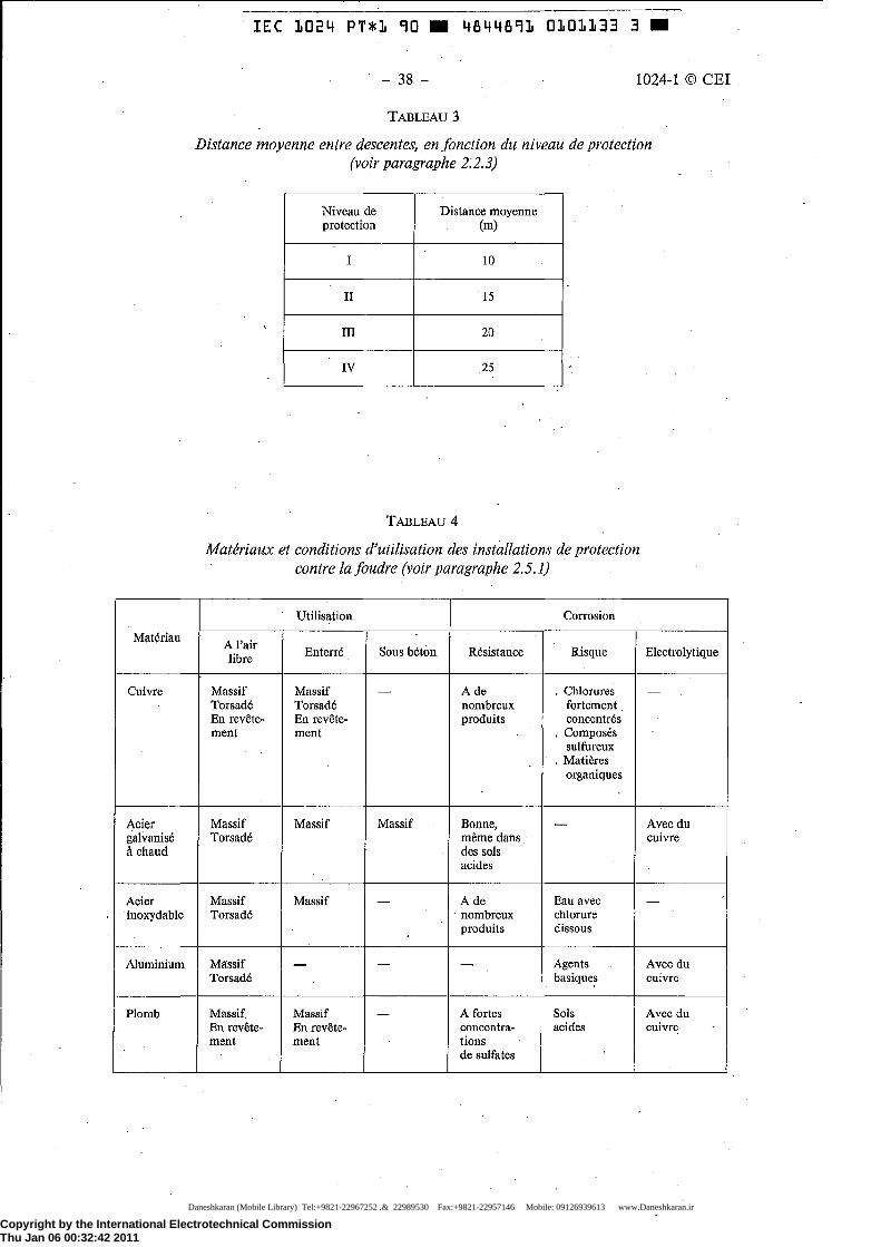
Copyright by the International Electrotechnical CommissionThu Jan 06 00:32:42 2011
Materiau
Cuivre
Acier galvanise a chaud
Acier -inoxydable
Aluminium
Plomb
IEC 1024 PT*1 90 II 4844891 0101133 3 II
- 38 - 1024-1 © CEI
TABLEAU 3
Distance moyenne entre descentes, en fonction du niveau de protection (voir paragraphe 2:2.3)
Niveau de Distance moyenne protection (m)
I 10
II 15
ill 20
IV 25
TABLEAU4
Materiaux et conditions d'utilisation des installations de protection contre lafoudre (voir paragraphe 2.5.1)
A I' air libre
Massif Torsade En revete-ment
Massif Torsade
Massif Torsade
Massif Torsade
Massif En revetement
Utilisation
En terre
Massif Torsade En revete-ment
Massif
Massif
-
Massif En revetement
Sous beton
-
Massif
-
-
Resistance
A de nombreux produits
Bonne, meme dans des sols acides
A de · nombreux
produits
-
A fortes concentrations de sulfates
Corrosion
Risque
. Chlorures fortement con centres
. Composes sulfureux
. Matieres organiques
-
Eau avec chlorure dis so us
Agents basiques
Sols acides
Electrolytique
-
Avecdu cuivre
-
Avec du cuivre
Avec du cuivre
Daneshkaran (Mobile Library) Tel:+9821-22967252 & 22989530 Fax:+9821-22957146 Mobile: 09126939613 www.Daneshkaran.ir
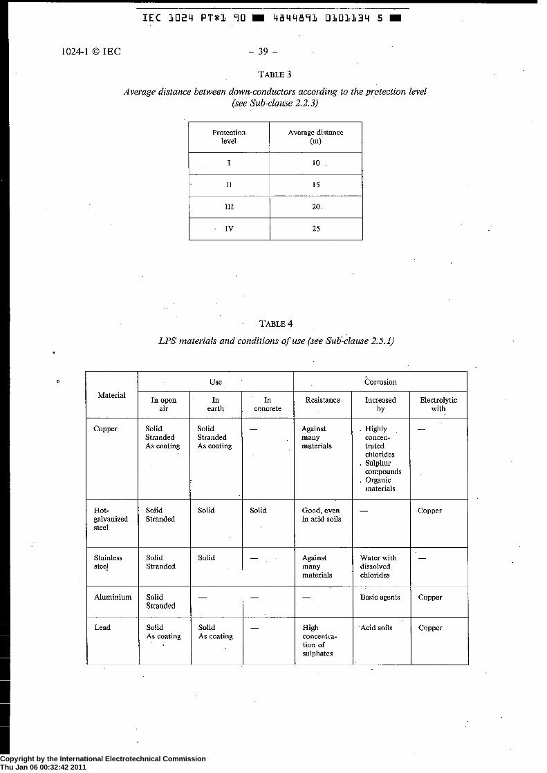
Copyright by the International Electrotechnical CommissionThu Jan 06 00:32:42 2011
IEC 1024 PT*1 90 .. 4844891 0101134 5 ..
1()24-1 © IE C 39 -
TABLE 3
Average distance between down-conductors according to the p1:otection level (see Sub-clause 2.2.3)
Material
Copper
Hot-galvanized steel
Stainless stee}
Aluminium
Lead
Protection Average distance level (m)
I 10
II 15
III 20
IV 25
TABLE4
LPS materials and conditions of use (see Sub:clause 2.5.1)
Use
In open In In air earth concrete
Solid Solid -Stranded Stranded As coating As coating
Solid Solid Solid Stranded
Solid Solid -Stranded
Solid - -Stranded
Solid Solid As coating As coating
Resistance
Against many materials
Good, even in acid soils
Against many materials
-
High concentration of sulphates
Corrosion
Increased by
. Highly concen-trated chlorides
. Sulphur compounds
. Organic materials
-
Water with dissolved chlorides
Basic agents
Acid soils
Electrolytic with
-
Copper
-
Copper
Copper
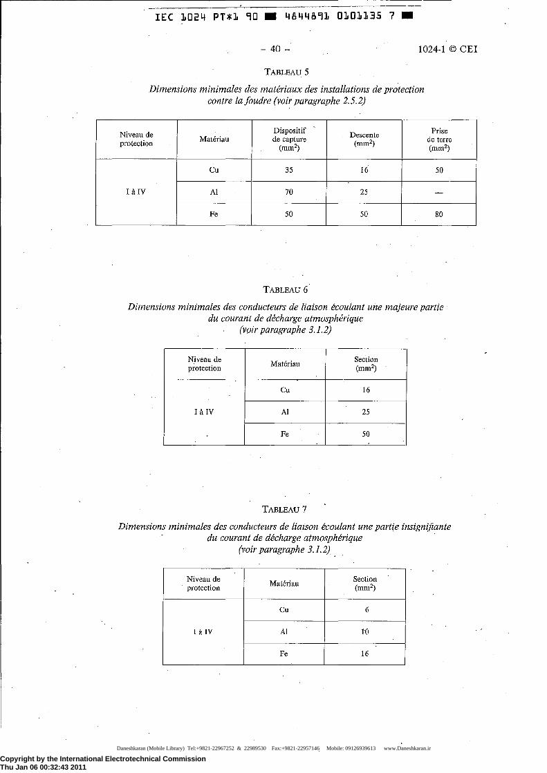
Copyright by the International Electrotechnical CommissionThu Jan 06 00:32:43 2011
IEC 1024 PT*1 90 II 4844891 0101135 7 II
- 40 - 1024-1 © CEI
TABLEAU 5
Dimensions minimales des materiaux des installations de protection contre lafoudre (voir paragraphe 2.5.2)
Niveau de Dispositif Descente protection Materiau de capture
(mm2) (mm2)
Cu 35 16
Ill IV AI 70 25
Fe 50 50
TABLEAU 6
Prise de terre (mm2)
50
-
80
Dimensions minimales des conducteurs de liaison ecoulant une majeure partie du courant de decharge atmospherique
(voir paragraphe 3.1.2)
Niveau de Materiau
Section protection (mm2)
Cu 16
IaiV AI 25
Fe 50
TABLEAU 7
Dimensions minimales des conducteurs de liaison ecoulant une partie insigni.fiante du courant de decharge atmospherique
Niveau de protection
Ill IV
(voir paragraphe 3.1.2)
Materiau
Cu
I AI
I Fe
I
Section (mm2)
6
10
16
Daneshkaran (Mobile Library) Tel:+9821-22967252 & 22989530 Fax:+9821-22957146 Mobile: 09126939613 www.Daneshkaran.ir

Copyright by the International Electrotechnical CommissionThu Jan 06 00:32:43 2011
1024-1 © IEC
Protection level
I to IV
I I I I I I -
IEC 1024 PT*1 90 .. 4844891 0101136 9 ..
- 41 -
TABLE 5
Minimum dimensions of LPS materials. (see Sub-clause 2.5.2)
Air- Down-Material termination conductor
(mm2) (mm2)
Cu 35 16
Al 70 25
Fe 50 50
TABLE 6
Minimum dimensions for bonding conductors canying a substantial part of lightning current
(see Sub-clause 3.1.2)
Protection Material
Cross section level (mm2)
Cu 16
. Ito IV Al 25
Fe 50
TABLE 7
Minimum dimensions for bonding conductors carrying no significant part of lightning current
(see Sub-clause 3.1.2}
Protection Material
- Cross section level (mm2)
r, "'
I to IV .AJ 10
Fe 16
Earth-· termination
(mm2)
50
-
80
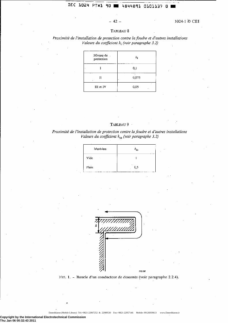
Copyright by the International Electrotechnical CommissionThu Jan 06 00:32:43 2011
IEC 1024 PT*1 90 II 4844891 0101137 0 II
- 42 - 1024-1 © CEI
TABLEAUS
Proximite de !'installation de protection contre lafoudre et d'autres installations Valeurs du coefficient ki (voir paragraphe 3.2)
Niveau de ki protection
I 0,1
II 0,075
III et IV 0,05
TABLEAU 9
Proximite de !'installation de protection contre Ia foudre et d'autres installations Valeurs du coefficient krn (voir paragraphe 3.2)
Materiau km
Vide 1
Plein 0,5
FIG. 1. - Boucle d'un conducteur de descente (voir paragraphe 2.2.4).
Daneshkaran (Mobile Library) Tel:+9821-22967252 & 22989530 Fax:+9821-22957146 Mobile: 09126939613 www.Daneshkaran.ir

Copyright by the International Electrotechnical CommissionThu Jan 06 00:32:43 2011
1024-1 © IEC
IEC 1024 PT*1 90 .. 4844891 0101138 2 ..
- 43-
TABLE 8
Proximity of installations to LPS Values of coefficient ki (see Sub-clause 3.2)
Protection level lq
I 0.1
II O.D75
III and IV 0.05
TABLE 9
Prox~mity of installations to LPS Values of coefficient km (see Sub-clause 3.2)
Material km
Air 1
Solid 0,5
FIG. 1. - Loop in a down-conductor (see Sub-clause 2.2.4).

Copyright by the International Electrotechnical CommissionThu Jan 06 00:32:43 2011
IEC 1024 PT*1 90 II 4844891 0101139 4 II
- 44 - 1024-1 © CEI
lt(m)
100
90
80 Niveau I L
70 v
~ 1/ I' ...;v-60
/ ~I'
50
L ~ v 40
30 ~ v
/ ~ v 20
v /
v Niveaux II a IV 10
...... I 0
0 . 500 1 000 1 500 2000 2500 3000p (Q. m)
221/90
FIG. 2. - Longueur minimale /1 des prises de terre, en fonction des niveaux de protection (voir paragraphes 2.3.2 et 2.3.3). Les niveaux II a IV sont independants de Ia resistivite p du sol.
-~ ·l_ LiQ"' o" "'"lpomoot m6t•liiq"'
D~oonte -~-
// 222/90
FIG. 3. - Proximite de !'installation de protection centre la .foudre et d'autres installations. Valeur du coefficient kc dans une configuration a une dimension (voir paragraphe 3.2).
Daneshkaran (Mobile Library) Tel:+9821-22967252 & 22989530 Fax:+9821-22957146 Mobile: 09126939613 www.Daneshkaran.ir
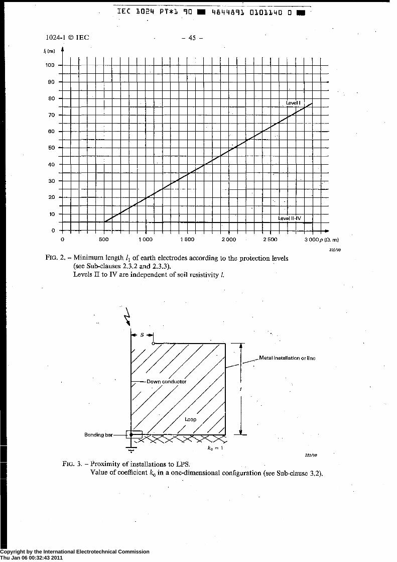
Copyright by the International Electrotechnical CommissionThu Jan 06 00:32:43 2011
IEC 1024 PT*1 90 .. 4844891 0101140 0 ..
1024-1 © IEC - 45 -
/j(m)
80 ~~~~-+-+-+-+~-4-4~~~~~~~+-+-+-+-~~-r-r-r-r-T~-ve*I~I+/-+-+-V
70 4-+-+-~~-+-+~~4-+-+-~~-t-r-r~~+-T-~~-t~~~~~T-
60 ...... v 1/v
40
0 I I
0 500 1 000 1 500 2000 2500 3000p (0. m)
221190
FIG. 2.- Minimum length /1 of earth electrodes according to the protection levels (see Sub-clauses 2.3.2 and 2.3.3). · Levels II to IV are independent of soil resistivity l.
·~
222/90
FIG. 3. - Proximity of installations to LPS. Value of coefficient kc in a one-dimensional configuration (see Sub-clause 3.2).

Copyright by the International Electrotechnical CommissionThu Jan 06 00:32:43 2011
IEC 1024 PT*1 90 .. 4844891 0101141 2 ..
- 46 - 1024-1 © CEI
~ ... sj4-
% l ~ I
/~ ~><:X
k 0 = 0,66 223/90
FIG. 4. - Proximite de !'installation de protection contre la foudre et d'autres installations. Valeur du coefficient kc dans une configuration a deux dimensions (voir paragraphe 3.2).
FIG. 5. - Proximite de !'installation de protection contre la foudre et d'autres installations. Valeur du coefficient kc dans une configuration a trois dim~nsions (voir paragraphe 3.2),
Daneshkaran (Mobile Library) Tel:+9821-22967252 & 22989530 Fax:+9821-22957146 Mobile: 09126939613 www.Daneshkaran.ir

Copyright by the International Electrotechnical CommissionThu Jan 06 00:32:43 2011
IEC 1024 PT*1 90 .. 4844891 0101142 4 ..
1024-1 © IEC - 47 -
~ ~--------------,----------------.---------------,
..... s 14--
X<><:--x kc = 0,66
223190
FIG. 4. - Proximity of installations to LPS. Value of coefficient kc in a two-dimensional configuration (see Sub-clause 3.2).
kc = 0.44 224/90
FIG. 5. - Proximity of installations to LPS. Value of coefficient kc in a three-dimensional configuration (see Sub-clause 3.2).

Copyright by the International Electrotechnical CommissionThu Jan 06 00:32:44 2011
IEC 1024 PT*1 90 .. 4844891 0101143 b ..
Publications de Ia CEI pn'iparees par le Comite d'Etudes n° 81
1024: - Protection des structures contre Ia foudre 1024-1 (1990) Premiere partie: Principes generaux.
Publication I 024-1
IEC publications prepared by Technical Committee No. 81
1024: - Protection of structures against lightning. 1024-1 (1990) Part 1: General principles.
Daneshkaran (Mobile Library) Tel:+9821-22967252 & 22989530 Fax:+9821-22957146 Mobile: 09126939613 www.Daneshkaran.ir