north bexhill access road - ground engineering
TRANSCRIPT

North Bexhill Access Road:Use of Ground Improvement by CMCs to Support a Reinforced EarthEmbankment
Frederic Bedoin – VM Chief Engineer
Josh Chastney – CR Geotechnical Engineer
9-Oct-18 Ground Engineering - Transport Geotechnics - 03/10/18 1

North Bexhill Access Road Project Introduction
Project Overview and constraints
Ground Conditions / Geotechnical Hazards
Initial Proposals
Alternative VE Solution
CMC Rigid Inclusion
Design Principles
Methodology
FE models
Conclusions
Agenda
3
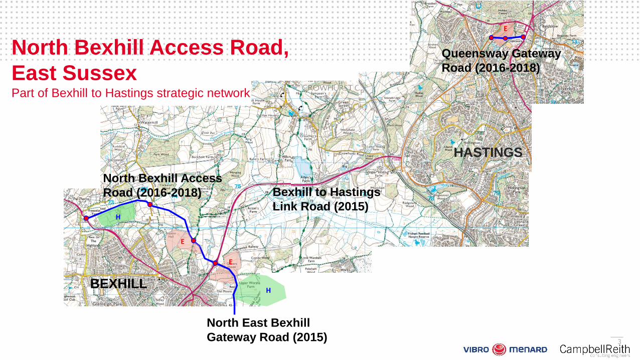
North East Bexhill
Gateway Road (2015)
HASTINGS
BEXHILL
Bexhill to Hastings
Link Road (2015)
Queensway Gateway
Road (2016-2018)
H
E
E
H
North Bexhill Access
Road (2016-2018)
North Bexhill Access Road,
East SussexPart of Bexhill to Hastings strategic network
E

Project Overview
9-Oct-18 Ground Engineering - Transport Geotechnics - 03/10/18
4
North Bexhill Access Road Alignment
Sidley (A269)
Project Specifications
£15.0m scheme.
Lead Designer: CampbellReith
2.4km single carriageway road linkingSidley in the west and the Bexhill andHastings to the east.
Constraints Crossing the Combe Haven Valley
Within a Flood Plain
Presence of an ecological corridor
Road level required at 6m above thewatercourse.
Deep Alluvium

Original Proposal –Piled Bridge
9-Oct-18 Ground Engineering - Transport Geotechnics - 03/10/18
5
20m clear span bridge with piledabutments.
1 in 3 unreinforced embankmentslopes.
Driven piles + LTP below approachembankments.
Flood plain maintained underlyingbridge and with floodcompensations ponds
Ecological corridor maintainedunderlying bridge

Ground Conditions
9-Oct-18 Ground Engineering - Transport Geotechnics - 03/10/18
6
Majority of alignment directly underlain bysilts and clays of the Tunbridge WellsSand and the Wadhurst Clay.
Ground Investigation within the vicinity ofthe Combe Haven revealed a buriedvalley infilled with alluvium up to 8m bglcontaining fibrous peat layers up to 1m inthickness.
Strong limestone encountered withinbedrock strata at depth.
Shallow groundwater and within an areasusceptible to flooding.
Weathered
Bedrock
Flood Plain

Ground Conditions
9-Oct-18 Ground Engineering - Transport Geotechnics - 03/10/18
7
Weathered
BedrockPeaty Alluvium
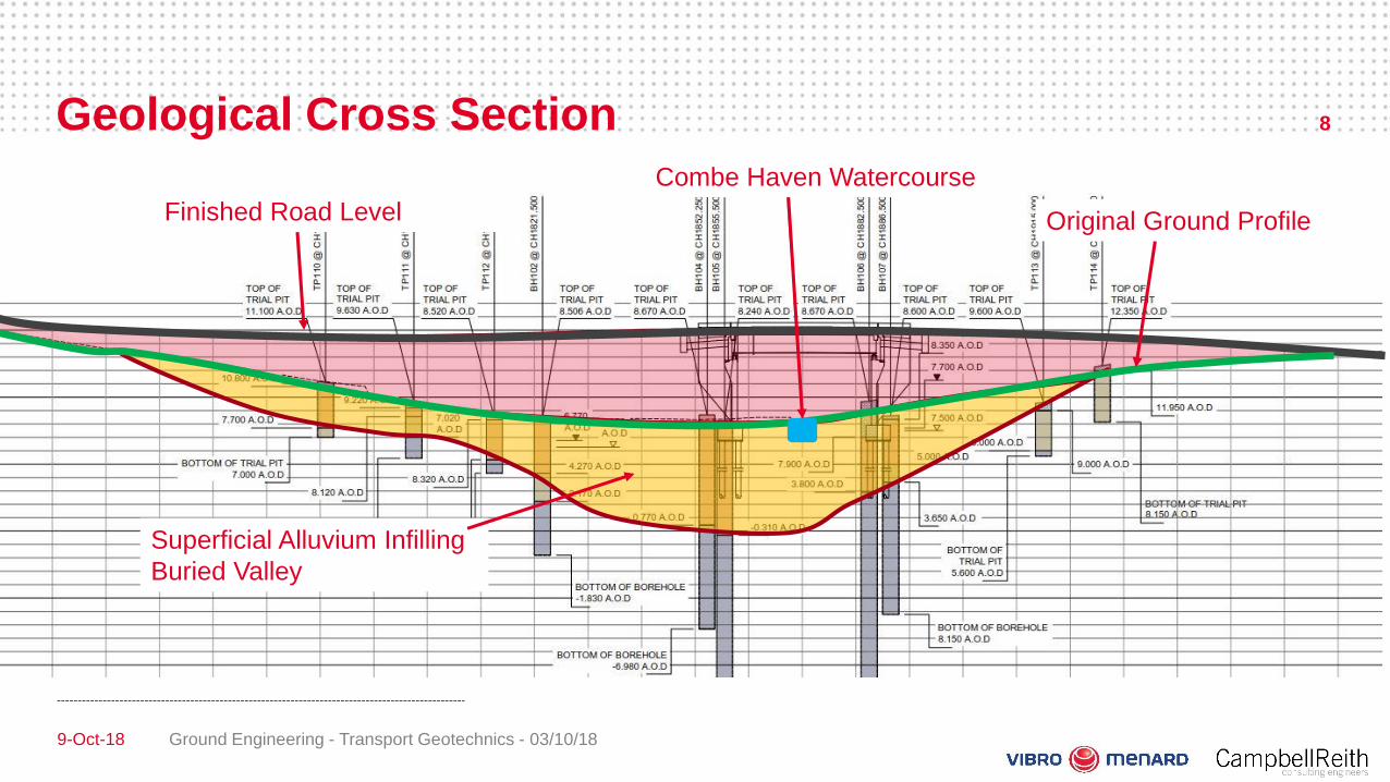
Geological Cross Section
9-Oct-18 Ground Engineering - Transport Geotechnics - 03/10/18
8
Combe Haven Watercourse
Original Ground Profile
Superficial Alluvium Infilling
Buried Valley
Finished Road Level

CPT Log
9-Oct-18 Ground Engineering - Transport Geotechnics - 03/10/18
9
Soil Conditions
Soft alluvium with bands of peat: upto 6.5m thick, qc=0.5MPa
Weathered Mudstone: 2m thick,qc=1MPa
Mudstone beyond: qc>4MPa

Value Engineered Solution (70 degree reinforced slopeand CMCs) 10
Embankment with 70⁰Reinforced Earth slope.
Precast culvert instead ofbridge.
Ground Improvement : CMCs
Load Distribution Mat of600mm
Increased area of floodcompensation ponds
Inclusion of numerousmammal and amphibiantunnels.
Design Life: 120 Years.

CMC Rigid Inclusions
9-Oct-18 Ground Engineering - Transport Geotechnics - 03/10/18
11
Design Principles
Group of concrete or mortar unreinforced* columns installed with a displacement* tool down to a more
competent layer
Increase the stiffness of the soil mass to globally reduce both total and differential settlements by
sharing the load of the structure between the soils and the CMC
To be associated with a distribution mat under uniformly distributed loads (slabs, embankments)
Worldwide recognized technique
0
500
1000
1500
2000
2500
3000
0
50
100
150
200
250
300
350
400
450
Cum
ula
ted
Yearly

CMC Rigid Inclusions
9-Oct-18 Ground Engineering - Transport Geotechnics - 03/10/18
12
Design Principles
Piles CMC
100% of the load
in the piles
No load in the soil
Share of the load
between the CMC
and the soil
EmbankmentEmbankment
WP/LDM (granular layer)LTP (geogrid)
WPBasal reinforcement
(not systematic)
CMC Rigid Inclusions
9-Oct-18 Ground Engineering - Transport Geotechnics - 03/10/18
13
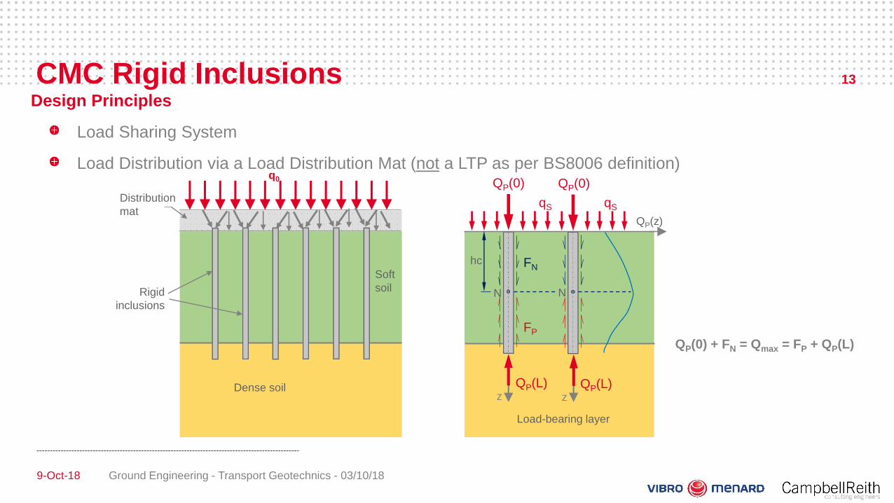
Design Principles
Load Sharing System
Load Distribution via a Load Distribution Mat (not a LTP as per BS8006 definition)
Load-bearing layer
QP(0) + FN = Qmax = FP + QP(L)
Dense soil
Soft
soil
Distribution
mat
Rigid
inclusions
q0 QP(0) QP(0)
qS qS
QP(z)
z z
FP
FN
N N
hc
QP(L) QP(L)

CMC Rigid Inclusions
9-Oct-18 Ground Engineering - Transport Geotechnics - 03/10/18
14
Methodology
CMCs embedded 0.5 to 1m within stiffer material (weathered Mudstone)
Use of a Soil Displacement Auger (Minimum spoils)
Grouting whilst extraction of the tool under low pressure
1 - Drilling down to the stiff layer:- horizontal soil displacement
- no surface spoils
2 - Grouting up to the surface:- computer control Improved soil/column friction ratio
No surface spoils
Soil displacement
CMC Rigid Inclusions
9-Oct-18 Ground Engineering - Transport Geotechnics - 03/10/18
15
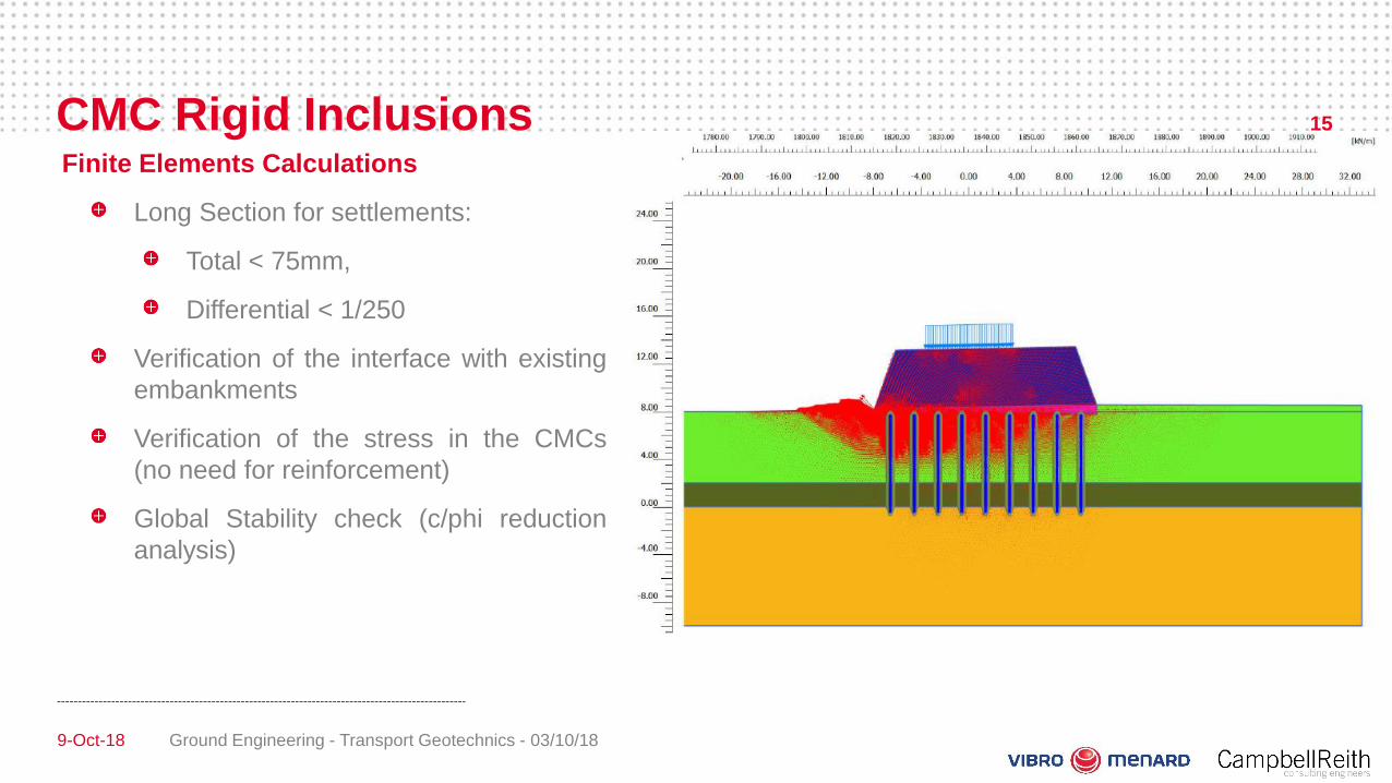
Finite Elements Calculations
Long Section for settlements:
Total < 75mm,
Differential < 1/250
Verification of the interface with existing
embankments
Verification of the stress in the CMCs
(no need for reinforcement)
Global Stability check (c/phi reduction
analysis)

CMC Rigid Inclusions
Ground Engineering - Transport Geotechnics - 03/10/18
16
9-Oct-18
Controls/Monitoring
Calibration
Drilling/Concreting logs
Static Load Tests
Settlements Monitoring

ConclusionGeotechnical Valued Engineering Solution:
Significant saving on material using a 70° slope RE embankment
Replacement of the bridge by a precast culvert
Ground improvement by Controlled Modulus Columns
Use of a CMC rigid inclusion solution:
Under Reinforced Earth Embankment up to 6m high
Lighter basal reinforcement (geotextile) and no need for reinforcement in the CMCs
Reduction of the settlements
Increase of the soil bearing capacity
Increase of the global stability
Execution and controls of the CMCs:
789 rigid inclusions of 7.5m average installed in 3 weeks
1 rig with soil displacement auger
Monitoring of the settlement during the embankment construction
9-Oct-18 Ground Engineering - Transport Geotechnics - 03/10/18
17

Conclusion
9-Oct-18 Ground Engineering - Transport Geotechnics - 03/10/18
18
Conclusion
9-Oct-18 Ground Engineering - Transport Geotechnics - 03/10/18
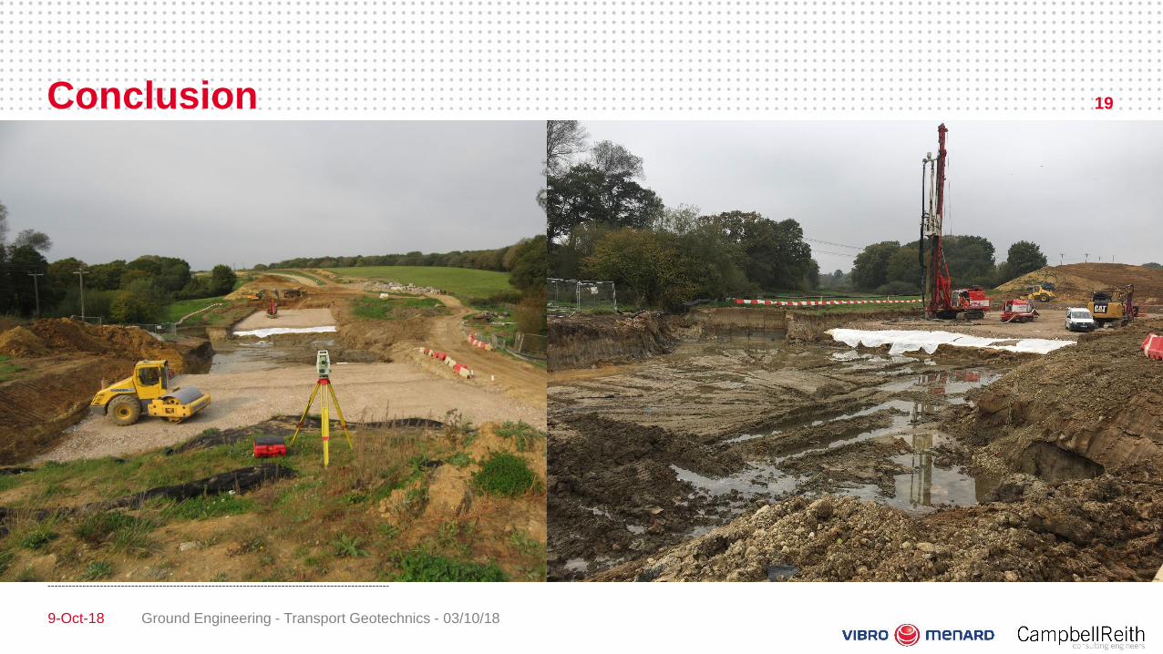
19

Conclusion
9-Oct-18 Ground Engineering - Transport Geotechnics - 03/10/18
20

Conclusion
9-Oct-18Ground Engineering - Transport
Geotechnics - 03/10/18
21

Conclusion
9-Oct-18Ground Engineering - Transport
Geotechnics - 03/10/18
22
