north carolina forestry best management practices manual...
TRANSCRIPT

North Carolina
ForestryBest Management Practices
Manual
To ProtectWater Quality
Amended September 2006

North Carolina Forestry Best Management Practices Manual To Protect Water Quality.Amended September 2006.
First Printing: December 2006.6,000 copies of this public document were printed at a cost of $37,198.82.----------------------------------------North Carolina Division of Forest Resources publication number FM-08-01.
This document and the companion North Carolina Forestry BMP Quick-Reference Field Guidereplace all versions and printings of the following publications and brochures:− Best Management Practices Checklist for Forest Harvest Operations. Multiple printings.
North Carolina Division of Forest Resources publication number WQ0295.− Best Management Practices for Forestry in the Wetlands of North Carolina - June 1990.
North Carolina Department of Environment, Health, and Natural Resources.− Forestry Best Management Practices Manual - September 1989.
North Carolina Division of Forest Resources, Department of Environment, Health, and Natural Resources.− Pocket Guide to the Forest Practices Guidelines Related to Water Quality. Multiple printings.
North Carolina Division of Forest Resources publication number WQ0501.− Riparian Forest Buffers. Multiple printings.
North Carolina Division of Forest Resources publication number WQ0198.
This Forestry Best Management Practices Manual was amended as allowed under 15 NCAC 1I .0101(c) withrevisions guided under the direction of:− Technical Advisory Committee for the Forest Practices Guidelines Related to Water Quality as established and
defined under N.C. General Statute Ch.113A-52.1(c).− Director and technical staff of the North Carolina Division of Forest Resources.
The State of North Carolina is an equal opportunity / affirmative action employer. Its programs, activities andemployment practices are available to all people regardless of race, color, religion, sex, age, national origin, handicapor political affiliation.
Michael F. EasleyGovernor
State of North Carolina
William G. Ross Jr.Secretary
Department of Environment and Natural Resources
Daniel E. SmithActing Director
Division of Forest Resources

North Carolina Forestry BMP ManualAmended 2006
iii
FundingFunding for the development and publication of this 2006 revision was provided, in part, through (listed alphabetically):
Albemarle - Pamlico National Estuary Programwww.apnep.org
Forestry Nonpoint Source Unit of the N.C. Division of Forest Resourceswww.dfr.state.nc.us/water_quality/wq_npsunit.htm
Natural Resources Leadership Institute of the N.C. Cooperative Extension Servicewww.ces.ncsu.edu/depts/agecon/nrli/index.htm
North Carolina Division of Forest Resourceswww.dfr.state.nc.us
USDA-Forest Service Forest Land Enhancement Programwww.fs.fed.us/spf/coop/programs/loa/flep.shtml
U.S. Environmental Protection Agency Nonpoint Source 319 Grant Programwww.epa.gov/owow/nps/cwact.html
Authors and Content ContributorsSean Brogan: N.C. Division of Forest ResourcesTom Gerow, Jr.: N.C. Division of Forest ResourcesJames D. Gregory, PhD: N.C. State University Department of Forestry & Environmental ResourcesMoreland Gueth: N.C. Division of Forest ResourcesRick Hamilton: N.C. Cooperative Extension Forestry Department of N.C. State UniversityKelly M. Hughes: N.C. Wildlife Resources CommissionWilliam Swartley: N.C. Division of Forest ResourcesLloyd Swift, Jr., PhD (ret.): USDA-Forest Service Coweeta Hydrologic Laboratory
North Carolina Forestry Technical Advisory CommitteeSector Individual Affiliation
Academic Community Rick Hamilton NCSU Extension ForestryConservation Community Will McDow Environmental DefenseConsulting Forester Richard Ellis Ellis and Holmes, LLCErosion & Sediment Control (Chair) Prof. Maurice G. Cook, PhD (ret) NCSU Department of Soil Science;
N.C. Division of Soil & Water ConservationForest Landowner Dr. J. Mack Hester, MD (ret) Forest LandownerForest Products Industry Jim Sitts Columbia Forest Products Corp.Marine Fisheries Mike Street N.C. Division of Marine FisheriesUSDA-Forest Service Lloyd Swift, Jr., PhD (ret) Coweeta Hydrologic LabWater Quality Prof. James D. Gregory, PhD NCSU Department of Forestry and
Environmental ResourcesWildlife Management Wib Owen N.C. Wildlife Resources Commission
More information about the TAC, including detailed minutes from meetings related to the development of this document can be
found at: www.dfr.state.nc.us/water_quality/wq_tac.htm
AcknowledgmentsDocument layout, formatting and technical editing by Tom Gerow Jr., BMP Staff Forester, N.C. Division of Forest Resources.Additional agency personnel also contributed to the revision of this manual and their investment of time is appreciated:N.C. Department of Environment and Natural Resources: Jamie KritzerN.C. Division of Forest Resources: Dave Andres; Jennifer Rall; Larry Such; Victoria TillotsonUSDA-Natural Resources Conservation Service: Robert Horton

North Carolina Forestry BMP ManualAmended 2006
iv
November 7, 2006
As participant-members of the Technical Advisory Committee for the Forest Practices Guidelines Related toWater Quality, as defined within N.C. General Statute 113A-52.1(c), and/or stakeholder participants in the first-ever revision to North Carolina’s forestry best management practices, we present the new North Carolina ForestryBest Management Practices Manual to Protect Water Quality.
This revised Best Management Practices (BMP) Manual is the result of nearly four years of deliberation, scrutinyand two rounds of technical peer review by professionals from across North Carolina. Agencies that reviewedthe document include the U.S. Army Corps of Engineers, U.S. Environmental Protection Agency and the NorthCarolina Division of Water Quality. The recommendations in this new BMP Manual have been carefullyconsidered for their merits related to the continued protection of water quality during forestry activities.
Built upon the expertise found within the multi-interest stakeholder participants, the recommendations in thisnew manual embody the concepts of forestry best management practices, as defined in North CarolinaAdministrative Code 15A NCAC 01I .0102 (4), whereas:
“Best Management Practice (BMP) means a practice, or combination of practices, that is determined to be an effective andpracticable (including technological, economic, and institutional considerations) means of preventing or reducing the amountof pollution generated by nonpoint sources to a level compatible with water quality goals.”
We are proud to have contributed our time, thought and energy to the development of this comprehensivecollection of BMPs that enhances the value of working forests as a viable and sustainable part of NorthCarolina’s landscape for future generations.
North Carolina Forestry BMP Manual Chapter 5Amended 2006 Page 50 of 243
Chapter 5Runoff Control and Forestland Access
Chapter 5 Layout:Part 1 - Page 51BMP Tools to ControlRunoff
Part 2 - Page 60BMP Tools to CaptureSediment
Part 3 - Page 68Stream Crossings
Part 4 - Page 78Forest Roads
Part 5 - Page 84Skid Trails
Part 6 - Page 86Decks & Landings
-- -- -- --
Helpful Hints:
Remember the four keyelements forcontrolling runoff:1 - Prevent It2 - Slow it down3 - Spread it out4 - Capture it
FPGFPGFPGFPGRefer to the FPGsin the Appendix
Take note of how this chapter is organized:
Part 1 describes methods to control runoff, while Part 2 includes practices tocapture sediment. These two topics are explained first because implementingthese types of ‘BMP tools’ are essential for properly built stream crossings,roads, skid trails and decks.
Also note in this Chapter (and throughout this manual), that the term ‘runoff’refers to surface runoff that flows atop the ground surface. This term shouldnot be confused with below-surface or groundwater flow.
Water Quality LinkThe BMPs in this chapter can help you plan, put into place, and maintain goodaccess in a way that should protect water quality:� Roads, skid trails, stream crossings and decks are widely considered the
most likely source of potential erosion and nonpoint source pollution on aforestry operation.
� Having BMPs correctly implemented can add value to the forestland for itsowner and to those who benefit from the land or its resources.
� Not having these features done the right way may lead to prolonged andsubstantial erosion and water quality problems that will likely cost muchmore to repair than it would have taken to prevent them in the first place.
‘Getting the Job Done …’Your ultimate goal is to protect water quality when working with roads, skidtrails, stream crossings, or decks. Preventing runoff, controlling runoff and/orcapturing sediment can go a long way towards accomplishing this goal.
Whether it is accomplished by using the BMPs in this manual, or by someother methods, the result must be the same: protecting the water.
Text Box for Rules References
Under each part of this chapter, a text box similar to this one containsreferences to those rules that may apply to that topic.
� There are several state and/or federal rules that apply to the features
discussed in this chapter, including most of the North Carolina FPGs.
� Specific requirements about forest roads in wetlands are briefly
discussed in this chapter. Refer to Chapter 6 for detailed information.

North Carolina Forestry BMP Manual Chapter 5Amended 2006 Page 51 of 243
Did You Know?
The type of BMP tools inParts 1 and 2 have manycommon names:
− Water controlstructures
− Erosion controlstructures
− Water diversions
− Runoff diversions
− Drainage structures
− Drainage diversions
No matter what you callthem, they serve thesame purpose ofcontrolling runoff andcapturing sediment.
Helpful Hints:
Table 5-1 is arranged tofocus first on the steepergrades, then recognizetheir correspondinglyshorter spacing ranges,as the slope gradeincreases.
The layout of this tableemphasizes the point thatsteeper slopes oftenrequire more BMPs tocontrol runoff.
Part 1 -- BMP Tools to Control Runoff
Controlling runoff reduces its speed and volume before it can get out of hand,thereby reducing the likelihood of accelerated erosion.
The BMP tools covered in Part 1 are:▪ Broad-based dip ▪ Waterbars▪ Turnouts ▪ Inside ditchlines▪ Cross-drains ▪ Insloping, outsloping and crowning
These different methods of controlling runoff can be used for nearly anysuitable forestry application. These may include permanent or temporaryroads, skid trails, stream crossings, firelines, access trails and log decks.
Installing these BMP tools usually is best during initial construction. However,they can be successfully retrofitted with proper equipment and techniques.
Locations where these BMP tools are especially useful include:• Steep slopes or slopes with soil of high erosion and runoff risk.• Top of slopes or grades to control runoff before it can pick up speed.• Approaches to stream crossings.
Some Benefits of Controlling Runoff� Protection of water quality from pollution potential by reducing erosion
risk and allowing better water absorption.� Improved access on your forestland.� Protection of your financial investment in sustaining forestland access.
Distance Spacing for Runoff Control BMPsTable 5-1 below provides a range of suggested spacings for installing thedifferent BMP tools used for controlling runoff. See ‘Helpful Hints’ to left.
The spacing ranges are only general guidelines and should be adjustedaccording to your specific site, soil, groundcover, equipment or otherconditions.
Table 5-1: Suggested Spacing Ranges for BMP Tools to Control Runoff
Slope Grade(percent)
Broad-based dips, Turnouts, Cross-drains(feet)
Waterbars(feet)
20 + 60 to 40 40 to 3016 to 20 100 to 60 60 to 4011 to 15 140 to 100 80 to 60 6 to 10 180 to 140 100 to 800 to 5 250+ to 180 120+ to 100

North Carolina Forestry BMP Manual Chapter 5Amended 2006 Page 52 of 243
Helpful Hints:
Broad-based dips arenot suitable toprovide drainage forInside Ditchlines orgroundwater seeps.Cross-drains should beused instead.
Helpful Hints:
Try to use the native soilfrom the site, andcompact it when formingthe reverse-grade hump.
Caption:In this photo, you can seethe dip in the road, andthe outlet created forcarrying runoff.
It is recommended to onlycreate enough outslopeangle within the dip toturn the runoff withoutcreating a hazardousdriving condition forvehicles.
Broad-Based DipA broad-based dip is a combination of a shallow depression (dip) excavatedinto the road surface with a slight hump at a reversed grade, formedimmediately on the downhill edge of this dip. An outlet area is provided forthe runoff to leave the road surface.
The dip works by diverting runoff away from the roadbed and through theoutlet. The hump acts as a barrier to continued runoff flow downhill along theroad surface.
BMPs for Broad-Based Dip• Lay out and construct the broad-based dip at right angle to the travel
surface and across the full width of the road.
• Excavate a shallow dip approximately 15 to 20 feet long into the uphilltravel surface.
• Construct and compact a slight hump across the downhill edge of the dip.The reverse grade of the hump should not exceed 2 to 3 percent slopedown toward the base of the dip.
• Outslope the bottom of the dip at enough of an angle to turn away waterand runoff, but generally no more than a 2 to 3 percent outslope angle.
• On slopes greater than 8 percent, or when needed, hardening the travelsurface of the broad-based dip with stone or other materials can preventerosion and improve vehicle traction.
� Situate the broad-based dip outlet in a manner that prevents runoff fromflowing directly into streams or waterbodies. Take measures to capture thesediment from the outlet as needed.
� Avoid siting the outlet onto soft soil or fill material, unless measures areimplemented to prevent accelerated erosion from the outlet.
Figure 5A: Cross-section view of a broad-based dip and outlet
Outlet stabilized with rock
Original grade
Road grade with dip

North Carolina Forestry BMP Manual Chapter 5Amended 2006 Page 53 of 243
Helpful Hints:
Waterbars are usuallyused when closing off,or 'retiring' skid trailsand roads.
It is not recommended todrive over waterbars,since this will wear downthe hump and alter thedrainage function of thetrench.
Watch Out!
Remember: Waterbarsare excavated andconstructed.
Simply piling soil on thetrail or road surface ISNOT the same asinstalling a waterbar.
Also Refer To…
Table 5-1 providesspacing ranges forwaterbars.
Helpful Hints:
Don't set the waterbarbackwards, which divertswater into the side / cutslope, unless there is anInside Ditchline to collectthe runoff.
WaterbarsA waterbar can be thought of as an angled ‘speed bump’ with a shallow trenchalong the uphill edge that diverts runoff. There are two key points to rememberfor functional waterbars:1. A waterbar must be constructed to extend completely across the trail
or road surface to be fully functional:
-- Doing so reduces the likelihood of runoff finding its way around the endsof the waterbar and flowing past it.
-- This may require ‘tying-in’ the waterbar with adjacent side / cut slopes.-- This may require extending the waterbar well beyond the width of the
road or trail travel surface.
2. The waterbar is not intended as a trap to block or pool runoff.
It should be angled and have a suitable outlet for diverting runoff into
an area where sediment will settle and/or filter out:
-- Proper angling is needed to allow the runoff to drain and not backup.-- Excavation of a shallow trench along the uphill edge of the waterbar
hump is helps collect and drain off the diverted water.
BMPs for Waterbars• Waterbars should be excavated and constructed using equipment and/or
techniques that assure proper angles and a firm waterbar hump.
• When building waterbars next to a side / cut slope, tie the uphill end of thewaterbar into the side / cut slope, and angle the waterbar downhill towardsthe outfall edge of the road or skid trail.
• Use an angle ranging from 15 to 30 degrees (downslope) for the waterbarto properly drain while preventing pooling of runoff behind it.
• Excavate the trench with enough gradient to allow adequate flow of waterrunoff, but generally not to exceed 2 to 3 percent.
� Situate the waterbar outlet in a manner that prevents runoff from flowingdirectly into streams or waterbodies. Take measures to capture thesediment from the outlet as needed.
� Avoid siting the outlet onto soft soil or fill material, unless measures areimplemented to prevent accelerated erosion from the outlet.
• Establish groundcover or harden the waterbar with stone or other material,if needed to maintain long-term function.

North Carolina Forestry BMP Manual Chapter 5Amended 2006 Page 54 of 243
Caption:The waterbar shown hereis properly angleddiagonally across the skidtrail, to allow runoff to flowoff the surface.
A shallow trench cancarry the runoff.
The waterbar and trenchextends past the edge ofthe skid trail to preventpassage of runoff aroundthe waterbar mound.
Caption:The trench that isexcavated along the uphillface of the waterbarallows water to flow offthe trail surface andthrough the outlet.
This outlet extends into awell-vegetated area thatprovides good infiltrationand sediment capturingeffectiveness.
NOTE -- Be sure tominimize any curvature ofthe waterbar across theroad or trail. Thewaterbar shown herewould be best if it were alittle less curved, but itappears that it shouldfunction satisfactorily.
Figure 5B: Waterbar constructed across a skid trail in Wilkes Co., N.C.
Figure 5C: View of the trench along the uphill face of the waterbar

North Carolina Forestry BMP Manual Chapter 5Amended 2006 Page 55 of 243
Caption:The waterbar in this photodemonstrates some goodBMPs to remember:-- Angled across the path-- Mounded soil waterbar-- Tied into side / cut bank(right side of photo)-- Outlet onto stable soil
NOTE -- A trench shouldbe excavated along theuphill base of thewaterbar, to carry runoffand keep the soil moundfrom getting ‘blown out.’
Did You Know?
The word turnout canalso be used to describea wide section of forestroad that allows vehiclesto pass each other.
Also Refer To…
Table 5-1 providesspacing ranges forturnouts.
Helpful Hints:
Remember, there are twoangles on a turnout:
� The outlet gradientangle is the slopeneeded to drain runofffrom the road surface.
� The turnout angledescribes how wideapart the turnoutveers away from theroadside or trail.
Figure 5D: A waterbar tied in to the adjoining side / cut bank
TurnoutsA turnout is a type of shallow trench or pathway that diverts runoff from thesurface of a road, skid trail or fireline.
A wing-ditch or lead-off ditch is a specific type of turnout used for controllingrunoff within roadside ditches.
In both cases, the turnout should be constructed as a continous offshoot of theroad, skid trail, fireline or roadside ditch. This helps maintain an uninterruptedconnection for runoff to flow.
BMPs for Turnouts• Begin the inflow of the turnout at the same grade level as the road, skid
trail, fireline or ditch so runoff can flow easily without being interrupted.
� Excavate the turnout with enough outlet gradient angle so runoff can drainin a controlled manner, generally from 1 to 3 percent is adequate.
• Construct using a turnout angle between 15 to 30 degrees downslope.
� Situate the end of the turnout outlet in a manner that prevents runoff fromflowing directly into streams or waterbodies. Take measures to capture thesediment from the outlet as needed.
� Avoid siting the outlet onto soft soil or fill material, unless measures areimplemented to prevent accelerated erosion from the outlet.
• For use in roadside ditches, take action to minimize erosion within thatditch so the inflow of the turnout does not create a gully.

North Carolina Forestry BMP Manual Chapter 5Amended 2006 Page 56 of 243
Caption:This turnout was pushedout into a vegetated areaso water can soak intothe ground and sedimentwill settle out.
Note the use of additionalwaterbars further downthe skid trail.
Caption:The turnout in this photois used as a wing ditch,which carries surfacerunoff from the roadsideinside ditchline (see nextsection for explanation).
The wing ditch or turnoutoutlets to a well-vegetated area.
Also note the slight humpin the road surface, whichhelps divert runoff into thewing ditch or turnout.
Figure 5E: A turnout used together with a waterbar on a skid trail
Figure 5F: A turnout, used as a wing ditch alongside aforest access road in Henderson County, N.C.

North Carolina Forestry BMP Manual Chapter 5Amended 2006 Page 57 of 243
Did You Know?
Other names for this:
− Inside ditch
− Grader ditch
− Shoulder ditch
Helpful Hints:
Ditchlines are most oftenneeded in sloping terrainwhere roads have a side /cut slope.
Additional BMP tools areoften needed so theditchlines don’t becomedeep gullies or constantsources of potentialerosion or pollution.
Ditchlines can be useful,though, when managinggroundwater seeps alongside / cut banks.
Watch Out!
The further apart you setturnouts or cross-drains,the more volume andspeed you will have tohandle within eachsection of ditchline.
Caption:In this photo, the insideditchline is located at thebase of the hill slope, atthe left edge of theroadbed.
The inside ditchlineappears to be stabilized,with no acceleratederosion or down-cuttingwithin the ditchline.
Inside DitchlinesAn inside ditchline provides a place to collect runoff that comes off the surfaceof an insloped or crowned road. The ditchline carries this runoff for a shortdistance until a cross-drainage technique is used to move the runoff from theinside edge of the road to the outside edge of the road, where the runoff drains.
Inside ditchlines can be difficult to correctly construct and maintain. WhileBMPs are provided below, you are encouraged to consider the alternative ofinstalling an outsloped road surface, which does not need inside ditchlines.
BMPs for Inside Ditchlines� Excavate the ditchline to the minimum depth and width needed to carry the
expected runoff from the road surface drainage area:-- The cross-sectional area within the ditchline should be matched to the
cross-sectional area of the pipe to be used for cross-drainage.-- A conservative rule of thumb is to approximately match the ditchline
cross sectional area to the same cross sectional area as a 15-inchdiameter pipe (1.25 square feet).
� Control runoff speed and volume to reduce the likelihood of creating ahigh-risk and long-term erosion hazard.
� Avoid allowing the ditchline to down-cut or become an erosion gully.Where appropriate, install geotextiles, matting, stone or other suitablematerial to reduce the potential for accelerated erosion.
� Install turnouts or cross-drains at intervals adequate to carry the expectedrunoff from each uphill section of ditchline and/or road surface.
� Situate the ditchline outlet or cross-drainage outlet in a manner thatprevents runoff from flowing directly into streams or waterbodies. Takemeasures to capture the sediment from the outlet as needed.
� Avoid siting the outlet on soft soil or fill material, unless measures aretaken to prevent accelerated erosion from the outlet.
Figure 5G: A forest road with an inside ditchline in Ashe County, N.C.

North Carolina Forestry BMP Manual Chapter 5Amended 2006 Page 58 of 243
Helpful Hints:
Cross-drains should useculvert pipes. The pipemust be large enough tocarry the runoff, but smallenough to fit within theroadbed.
Open-top drains ortrenches are notsuitable for forestryapplications.
Also Refer To…
Table 5-1 providesspacing ranges forcross-drains.
Watch Out!
Smaller pipe sizes caneasily get clogged withdebris and/or sediment.
If smaller pipes must beused, perform morefrequent regularinspection andmaintenance toremove blockages.
If plastic culverts are usedyou may need moresubstantial fill materialatop the pipe to providevehicle support.
Cross-DrainsCross-drains move water and runoff from one side of a road or trail to theother, usually under or through the roadbed.
Cross-drains can be used to:− Carry runoff out of an inside ditchline.− Drain water and runoff along grades.− Provide drainage for groundwater seeps or springs.− Direct runoff away from log decks.
BMPs for Cross-Drains� Set cross-drains on a 2 to 4 percent downslope angle to provide good
drainage and help prevent debris from clogging the drain.
� Install cross-drains at an approach angle suitable to allow free flow ofrunoff into and through the cross-drain.
� Match the base level of the cross-drain inflow to the base elevation of theditchline so runoff can flow into and through the cross-drain uninterrupted.-- A drop-inlet can improve inflow at places where the elevation of the
cross-drain inlet is lower than the ditchline.
� If culvert pipe is used, cover the pipe with at least one foot of fill andharden the crossing location as needed to protect the pipe from traffic:-- Use at least a 15-inch diameter pipe on heavy flow areas.-- Use at least a 12-inch diameter pipe if only needed for groundwater
seeps or for locations where minimal runoff volume and/or debris isexpected.
-- The cross-sectional area of the pipe should be matched to the cross-sectional area of the ditchline being drained.
� Minimize erosion on both ends of the cross-drain so the ditchline does notdown-cut and create a gully or produce accelerated erosion.
� Where needed, harden the inflow headwall of the cross-drain with stone,sandbags, geotextiles, vegetation, drop-inlet, or other suitable materials toavoid headcutting or accelerated erosion.
� Situate the cross-drain outlet in a manner that prevents runoff from flowingdirectly into streams or waterbodies. Take action to capture the sedimentbelow the outlet as needed.
� Avoid siting the outlet onto soft soil or fill material, unless measures areimplemented to prevent accelerated erosion from the outlet.

North Carolina Forestry BMP Manual Chapter 5Amended 2006 Page 59 of 243
Caption:This cross-drain providesdrainage of runoff thatflows within the insideditchline (which is locatedat the base of the slope inbackground, alongsideroad edge).
Note that the cross-drainis installed diagonallythrough the roadbed, toprovide improved flow ofthe water.
Also note that the culvertpipe extends well past thetravel surface of the road,to protect it from beingdamaged by vehicles.
For Forest Owners:
Insloped roads may besuitable on steep gradeswith slick soils and/orsharp curves, but requirethe excavation andmaintenance of an insideditchline, with cross-drains.
Outsloped roads, withappropriate water controlmeasures, are thepreferred road design insteep terrain. This designeliminates the need for aninside ditchline and allowsfor better control of runoff.
Watch Out!
Use whatever surfacedrainage method is bestto meet your safety needsfor slick soils, steepgrades, sharp curves,vehicle type(s) and trafficfrequency.
Figure 5H: View of the outlet end of a cross-drain installed underneath a permanent forest road in Wilkes County, N.C.
Insloping, Outsloping and CrowningThe degree to which a road surface is tilted or angled can determine a lot aboutrunoff flow. By insloping, outsloping or crowning a road surface, you arecreating a tilt or angle that naturally moves water and runoff from the surface.
Insloping allows runoff to drain into an inside ditchline. Because the ditchlineis between the uphill side / cut bank and the roadbed, the ditchline must bedrained with a turnout or cross-drain.
Outsloping allows runoff to drain from the road surface towards the outside(downslope) edge of the road, where the runoff can be controlled or allowed toabsorb into the ground. This method generally requires less maintenance thaninsloped roads because there are no, or very few, ditchlines or cross-drains.
Crowning creates a slight hump across the road’s cross section, by having thecenterline of the road higher than both roadside edges. If a road is to becrowned, other BMPs tools to collect and/or capture runoff may be needed.Crowning is usually used on wider, permanent access roads or in flat landswith a ditch on at least one side to collect runoff.
BMPs for Insloping, Outsloping and Crowning� On insloped roads, excavate and maintain inside ditchlines and cross-
drains in order to carry runoff. Refer to the BMPs for inside ditchlines.

North Carolina Forestry BMP Manual Chapter 5Amended 2006 Page 60 of 243
Caption:A crowned road mayneed slight berms and/orgrader ditchlinesalongside either edge tocontrol runoff.
An insloped road needsappropriate insideditchlines to collect runoff.A cross-drain (dotted line)is also needed to drainthe inside ditchline.
An outsloped road caneffectively use broad-based dips to managesurface water runoff.
� For freshly graded outsloped or crowned roads, a temporary low bermalong the outside (downslope side) edge of the road may prevent washingaway of the soft soil and fill material:-- If a temporary berm is installed, provide outlets or gaps so runoff can
move away from the road surface in a controlled manner.
� Maintain the road surface as needed to minimize or repair ruts, holes, ordepressions that hold water, which can weaken the roadbed or createconcentrated runoff with sediment transport.
Figure 5I: Schematic cross-sectional sketch ofcrowned, insloped and outsloped road surface profiles
Part 2 -- BMP Tools to Capture Sediment
Capturing or containing sediment is the second part of using BMPs related toroads, skid trails, stream crossings and decks.
Your first goal should be to prevent or halt accelerated erosion once you havecontrolled the runoff. When those efforts are not adequate, capturing thesediment before it reaches a stream is the last option you have:
-- Stop or prevent sediment transport at its source.-- If that doesn’t work, keep the sediment on site.-- Above all else, keep the sediment out of the streams and waterbodies.

North Carolina Forestry BMP Manual Chapter 5Amended 2006 Page 61 of 243
Caption:This temporary holdingarea, reinforced withstone, is successfullycapturing runoff andsediment.
The stone provides goodsupport and backing.
The BMP tools discussed in Part 2 are: ▪ Filter Areas ▪ Sediment Traps / Pits ▪ Silt Fences ▪ Straw Bales ▪ Brush Barriers ▪ Check Dams
Consider the long-term potential for effectiveness and maintenance whendeciding which BMP tools to use when capturing sediment.
Locations where these BMP tools are especially useful include:-- Disturbed soil areas near streams or other waterbodies.-- Approaches to stream crossings.-- Steep slopes or slopes with soil of high erosion and runoff risk.-- Along slopes or grades to periodically capture sediment in runoff.-- As a catchment for collected or diverted surface runoff.
Some Benefits of Capturing Sediment� Protection of water quality from pollution potential by containing sediment
in runoff before flow picks up speed and volume or enters a waterbody.� Improved access on your forestland.� Added value of your financial investment in sustaining forestland access.
Figure 5J: Temporary sediment capture alongside a forest road
Filter AreasFilter areas are usually a long-term, low-cost option to capture, slow, andcontain runoff so sediment and other potential pollution can settle out beforereaching a waterbody.
Filter areas can be differently shaped or sized, depending upon the applicationand needs of the soil and site.

North Carolina Forestry BMP Manual Chapter 5Amended 2006 Page 62 of 243
FPGFPGFPGFPGRefer to FPG .0201as it relates to SMZs,which are a type ofrequired filter area.
The DWQ riparian bufferrules are also a type ofmandatory filter areathat must be applied in
certain parts ofNorth Carolina.
Did You Know?
Other names for theseinclude:
− Sediment basins
− Settling pit
− Silt trap or silt pit
− Tank traps
Helpful Hints:
Traps or pits are effectiveto collect runoff that isdiverted by a broad-based dip, waterbar,cross-drain, turnout orditchline.
BMPs for Filter Areas� Permanent groundcover should be retained or established that allows
runoff to slow down and soak into the soil:-- Natural, relatively undisturbed groundcover and/or vegetation is usually
the best choice for a filter area.-- Established groundcover can also be effective, but may require
additional BMPs and/or maintenance.
� Intensive soil disturbance should be minimized.
� Use stable, well-drained soils for filter areas when available.-- If unstable soils must be used for a filter area, install treatments such as
erosion matting or other methods to stabilize the soil.
Sediment Traps or PitsSediment traps are excavated holes that trap and store runoff, and are usuallyinstalled where runoff is concentrated nearby streams and other waterbodies.
Traps or pits can be used for either temporary runoff control, or long-terminstallation. Permanent use of traps / pits will require more substantialconstruction and periodic maintenance.
BMPs for Sediment Traps or Pits� Excavate the pit with a suitable opening and depth to capture the expected
sediment runoff while minimizing soil disturbance to the adjacent area.Refer to Appendix 14 for suggested sediment pit sizing dimensions.
� Locate the pit within stable, well-drained soils when available.-- If the pit must be situated within unstable soils, install additional
measures to provide soil stabilization around the pit.
� Dispose or stabilize the excavated spoil material to keep it from washingaway. Avoid using the spoil to build up the sides of the pit, since this loosespoil material can easily wash away or fall back into the pit.
� For sediment pit installations intended to be permanently functional:-- Create a reinforced outlet for overflow capacity that will reduce the
likelihood of the pit walls being washed away or ‘blown out’.-- Harden the walls of the pit to minimize the risk of structural failure.-- Revegetate exposed soil around the perimeter of the pit.-- Periodically clean out accumulated sediment. A useful rule is whenever
the pit is half full, remove and stabilize the accumulated sediment.

North Carolina Forestry BMP Manual Chapter 5Amended 2006 Page 63 of 243
Caption:This sediment pit islocated in a good positionto capture sediment thatflows off of this graveled,outsloped forest road.
The pit is positioned wellaway from the stream(in background).
NOTE -- The headwall onthis pit may needreinforcement, or have tobe sloped back, to keepsoil from falling into the pitafter being saturated fromprecipitation.
Helpful Hints:
Silt fences are usuallyman-made materials.
Think of a silt fence assimilar to a coffee filter - -the idea is to capture thesediment in the runoff,while allowing the waterto still trickle through.
Figure 5K: A functioning sediment pit excavated alongside a forest road
Silt FenceSilt fence is a geotextile or fabric that is supported with stakes, with the bottompartially buried into the ground and is for temporarily capturing runoff.
A silt fence is most effective for temporarily capturing sediment and delayingrunoff that occurs across the ground surface, before reaching a channel orforming gullies and erosion trenches in the land.
Silt fence cannot effectively capture mass movement of sedimentor capture runoff for an extended period of time.
Silt fencing may be useful to capture sediment in areas of exposed bare soiluntil vegetation can be established. Due to the natural roughness and uneventerrain on forestry job sites, a silt fence can be very difficult to correctly installand still remain effective.
BMPs for Silt Fence� Additional measures upslope and downslope of the silt fence may be
required to slow, control and capture sediment.-- If there is considerable sediment build-up along the silt fence, determine
the sediment source and adjust or add BMPs accordingly.
� The suggested drainage area limit is 100 feet of fence for every one-quarteracre of land. Refer to Table 5-2 below for further reference.
� Set fencing along the land contours and extend the fencing far beyond theexpected pathway(s) of runoff flow. The ends of the fencing should begently turned like a sideways ‘J’, with the hook facing uphill.

North Carolina Forestry BMP Manual Chapter 5Amended 2006 Page 64 of 243
Watch Out!
Silt fence should never beused as the only BMPtool on the job site.
Additional BMPs areneeded to control runoffand capture sediment.
You should expect siltfencing to fail duringheavy precipitation - -plan accordingly.
If you observe a heavysediment accumulation,look up-slope and re-evaluate your BMPs.
Table 5-2 was adapted from N.C.Division of Land Resources’Erosion and Sediment ControlHandbook “Practice Standards andSpecifications.”
Caption:This sketch depicts theproper installation of siltfence.
Note the bottom of the siltfence along the upslopeside is buried into the soil,and the fence is securelystaked.
Consider setting multiplerows of fencing toprovide additionalprotection.
Avoid using silt fence todivert water - - it shouldbe used only as atemporary sediment filter.
(Illustration provided withpermission and courtesy ofMaine Forest Service).
� Bury the bottom 4 to 6 inches of silt fence securely into the ground to keeprunoff from flowing underneath:-- Install the fence so that the buried portion is along the upslope face of the
fence, to prevent the fence from getting washed over by sediment.
� Adequately reinforce the silt fencing from being knocked over or blownout. Wire fencing backer or additional staking can be used.
� Frequently monitor the silt fence after installation. Promptly take action tomaintain or improve the filtering effectiveness.
Table 5-2: Recommended Applications for Every 100 Feet of Silt Fence
Maximum Slope Length Maximum DrainageSlope Between Fence-rows (feet) Area (acres)
0 to 2% 100 0.23
2% to 5% 75 0.17
5% to 10% 50 0.11
10% to 20% 25 0.06
20% + 15 0.03
Figure 5L: Sketch of properly installed silt fence

North Carolina Forestry BMP Manual Chapter 5Amended 2006 Page 65 of 243
Helpful Hints:
Places where bales maybe helpful:
− Outlets of waterdiversion toolsdescribed in Part 1
− Stream crossingapproachways
− Alongside freshlygraded outslopedroads
− Around edges of logdecks
− Supporting orsupplementing siltfence installations
Caption:When bales are used tocapture sediment, youshould make sure that:-- Bottom of the balesconforms to the groundsurface to preventleakage.
-- Bales are secured ifneeded to prevent themfrom being washed away.
-- Joints betweensuccessive bales arestaggered like bricks.
(Illustration provided withpermission and courtesy ofMaine Forest Service)
Straw BalesStraw bales, or a bale of other natural fibers, can be a low-cost and effectivetool to slow runoff and capture sediment. Bales often are better than silt fenceor brush barriers since they can conform better to the ground surface.
Bales can be placed around the perimeter of an area with exposed soil, oracross the pathway of runoff flow. The bales will help control the runoff, andact as a sediment filter.
However, since they are natural fibers, the bales will eventually decomposeand breakdown. As a result, they should be used for temporary runoff captureand control.
BMPs for Straw Bales� Additional measures upslope and downslope of the bales may be needed to
slow, control and/or capture sediment.-- If there is considerable sediment build-up along the bales, determine the
sediment source and adjust your BMPs accordingly.
� Set bales tightly against the ground surface and anchor the bales firmly intothe soil if the bales are likely to wash away.
� If square bales must be stacked, stagger the joints between bales so they donot line up over the joints in the previous layer, similar to brick laying.
� Frequently monitor bales after installation. Promptly take action tomaintain or improve effectiveness.
Figure 5M: Sketch of bales used to capture sediment

North Carolina Forestry BMP Manual Chapter 5Amended 2006 Page 66 of 243
Helpful Hints:
Places where brushbarriers may be helpful:
− Alongside newlyconstructed or gradedroads
− Alongside and on topof skid trails
− Around edges of logdecks
− Stream crossingapproachways
Caption:The brush barrierinstalled along the rightedge of this stabilizedforest road will helpcapture sediment before itcan move downslope.
Caption:Brush has been laid downat the base of theroadbed, in the center ofthe photo. Also note thewell-vegetated roadbedand side / cut bank.
(Photo figure 5O providedcourtesy of Coweeta HydrologicLaboratory, Southern ResearchStation, USDA-Forest Service.)
Brush BarriersBrush barriers are piles of leftover, unusable tree and vegetation debris that iscarefully piled and packed down to act as a temporary filter barrier to slowrunoff and capture sediment.
Creating brush barriers is a productive use and disposal for debris that isgenerated by road or skid trail construction and can be a low-cost method oftemporary sediment capture.
BMPs for Brush Barriers� Pile and pack down brush to achieve close contact with the ground surface.
-- This may require breaking or cutting large pieces of material into smallerchunks that more easily conform to the surface of the ground.
� Use additional BMP tools such as silt fences, bales, filter areas or othermethods to improve trapping effectiveness where brush barriers fail tocapture enough sediment because of their loose configuration.
� Avoid removing the brush barrier once it is established.
Figure 5N: A brush barrier alongside a closed road in Caldwell Co., N.C.
Figure 5O: A brush barrier at the base of an active road

North Carolina Forestry BMP Manual Chapter 5Amended 2006 Page 67 of 243
Helpful Hints:
While usually constructedof stone rip-rap, checkdams can also be builtfrom sandbags, sacks ofconcrete, logs or othersuitable hardenedmaterials.
Watch Out!
Check dams are notappropriate forinstallation withinstreams.
Caption:These small check damsprovide sediment capturewithin a turnout thatdrains a graveled forestroad.
Note the sedimentaccumulation captured bythe front two check dams.
The rear two check damsappear to not have anysediment accumulationyet, but provide goodreinforcements.
The area is wellvegetated and stabilized.
Check DamsCheck dams are short, hardened barriers established within inside ditchlines toslow the speed of runoff and capture sediment. Check dams can also be usefulto control the runoff that comes from the outlets of water diversions (such asthose described in Part 1 of this chapter.)
BMPs for Check Dams� Consider laying down geotextile fabric before placing the check dam’s
construction material. This keeps material from sinking into the ground.
� Provide ample support at the base of the check dam in order to hold backand contain the sediment.
� Tie-in the base of the check dams with the soil to keep runoff from seepingunder or ‘blowing out’ around sides of the the dam location.
� The center of the check dam should be lower than each outer edge toprovide overflow capacity of water during heavy flows.
� The total height of the check dam should not exceed 3 feet. Tallerstructures are more prone to failure.
� Space the check dams within the channel so the top of each downslopecheck dam matches the same elevation as the base of the next higher dam.
� If check dam effectiveness is compromised by sediment buildup,periodically remove built-up sediment from behind the dams. Dispose ofor stabilize this material to keep it from washing into waterbodies.
Figure 5P: Check dams installed within a turnout from a forest road

North Carolina Forestry BMP Manual Chapter 5Amended 2006 Page 68 of 243
Helpful Hints:
BMPs for the four mostcommon types of streamcrossings are provided:
− Bridgemats
− Culverts
− Fords
− Pole Crossings
FPGFPGFPGFPG
FPGFPGFPGFPG
Helpful Hints:
Recommendations onstream crossings areavailable from:
− Consulting Foresters
− N.C. Division ofForest Resources
− Soil & WaterConservation Districts
− USDA-NaturalResourcesConservation Service(NRCS)
Part 3 -- Stream Crossings
Stream crossings are often necessary for roads, skid trails and firelines to gainaccess to forestland for management. Permanent crossings usually are forroads, or in some cases, firebreaks. Temporary crossings are most commonfor timber harvesting or other short-duration forestry operations, such as siteprep, tree planting, fertilization or herbicide application.
Because of the obvious potential for water quality impacts at stream crossings,there are several rules that require practices be used or actions taken. Since theNorth Carolina FPGs were enacted in 1990, stream crossings have been themost frequent location on a job site where sediment may get into the water.
Rules Related to Stream Crossings
Forest Practices Guidelines Related to Water Quality (FPGs)
North Carolina General Statute 77-13 and General Statute 77-14
DWQ riverbasin and watershed ‘Riparian Buffer Rules’
These ‘buffer rules’ for specific river basins and watersheds set limitations onstream crossings within the 50-foot buffer zone
North Carolina Dredge and Fill Law
This state law requires that permits be secured for discharges of dredged or fillmaterial in certain locations within the 20 Coastal Area Management Act(CAMA) counties. Refer to Chapter 6 for more information on this law.
Planning Stream CrossingsStream crossings should be carefully planned in advance of their need todetermine how water quality can be best protected. This section providessuggested BMPs when planning crossings.
BMPs for Planning Stream Crossings� Avoid having stream crossings if possible. Take note of the FPGs.
� Use maps, photos and/or on the ground examinations to determine theminimum number of crossings needed to efficiently access the propertywhile protecting water quality.
� Designate the location of the proposed stream crossing on the ground toavoid confusion about where to construct the crossing.
� When conditions allow, give preference to locations for crossings where:-- The stream is relatively straight so crossing distance is minimized.-- Approaches to the stream are relatively flat to better control runoff.-- The crossing can be installed at a right-angle (90°) to the stream channel
so crossing distance is minimized.

North Carolina Forestry BMP Manual Chapter 5Amended 2006 Page 69 of 243
FPGFPGFPGFPG
Caption:The BMPs noted here:- Properly sized culvert.
- Culvert installed tohandle low flow streamconditions.
- Sloped road fill,reinforced with a sidesupport log/timber.
- Ample fill material overthe culvert.
- Headwall reinforced withlarge rock.
A Note onPermanent Bridges:
Permanent bridgesrequire professionalengineering expertise.Specifications are beyondthe scope of this Manual.Some generic BMPs toconsider:
− Use bridges on deep,wide streams withheavy streamflows.
− Minimize soildisturbance duringconstruction.
− Avoid placing abridge in the curve ofa stream or road.
� Select the type of stream crossing(s) based on site characteristics and theability to best protect water quality while providing safe, efficient access.
� Maintain as close to normal (pre-construction) streamflow by maintainingdepth, width, gradient and capacity of the stream channel at the crossing.
� Perform construction, installation, and removal work during low-waterflow if circumstances allow.
� Stabilize the approachways and/or stream crossing locations so sediment isnot transported into the stream as prescribed in the FPGs.
Figure 5Q: A permanent stream crossing on a forest road
BridgematsBridgemats are heavy wood or steel panels placed over a stream or ditchchannel, usually for temporary crossing. Other names include dragline mats,skidder bridges or pontoons. When bridgemats are carefully installed, used,and removed, they typically do a very good job of protecting water quality.
BMPs for Bridgemats� When site conditions allow, select a stream crossing location that has these
characteristics:-- Narrow channel width.-- Firm, stable streambanks.-- Solid footing on either side to support bridgemats and equipment.-- High, level ground on each side.
� Create a solid-surface crossing that provides a barrier over the channel tominimize debris, soil, and other materials from falling into the water.
� Keep equipment out of the channel during installation and removal of thecrossing unless doing so is necessary for handling the bridgemats.

North Carolina Forestry BMP Manual Chapter 5Amended 2006 Page 70 of 243
A Note on Log Bridges:
Temporary crossingsconstructed of de-limbedlogs may be suitable incertain cases.
A log bridge is not thesame as a ‘pole crossing’,which is explained later inthis Chapter. A log bridgeshould completely spanthe watercourse:
− Avoid gouging ordamaging streamchannel with the logsas they are installedand removed.
− Keep logs butted tightto each other tominimize debris andsoil from fallingbetween.
− Keep equipment outof the stream whenplacing and removinglogs.
Caption:BMPs noted here include:
- Good support on eachend of the bridgemat.
- Adequate clearancebetween the stream flowand bridgemat.
- Three panels are usedto create full-widthcrossing, with no gaps.
� Minimize the amount of over-hang from logs, trees, or trucks/trailers thatmay disturb the channel or approachways.
� Control runoff and/or capture sediment on the approachways. See Part 1and Part 2 of this Chapter for possible options.
� As needed, periodically inspect the crossing and take action to provide forsafety while protecting water quality from runoff, debris, soil, or otherpotential pollution factors.
� Stabilize the approachways and crossing location in accordance withFPG .0203 and .0209.
Figure 5R: Schematic drawing of proper bridgemat installation
Figure 5S: Side view of a wooden bridgemat skid trail crossing

North Carolina Forestry BMP Manual Chapter 5Amended 2006 Page 71 of 243
Caption:BMPs noted here include:
- A full-width panelcrossing is used, with nocenter gap that couldallow debris to fall into thestream.
- A straight section ofstream is used for thecrossing location.
- The bridgemat ends arewell supported to preventdamaging the streambanks.
For Forest Owners
Smaller diameter culverts(less than 15 inches) canget clogged or blockedtoo frequently and createpotential water qualityproblems.
A single larger diameterculvert is usually betterthan multiple, smallerdiameter culverts sincethe smaller culverts maybe more prone toblockages.
The cross-sectional areaof a culvert openingcannot simply be addedtogether to determinemultiple culvert needs.Two 24 inch diameterpipes DO NOT providethe same volume as one48 inch diameter pipe.
Figure 5T: Steel bridgemat installed for a skid trail stream crossing
CulvertsCulverts are typically used for forest road stream crossings but can also beused for skid trail crossings. While culverts are readily available and can be arelatively inexpensive method, a major disadvantage of culverts is that theyrequire disturbance in the stream channel. That includes placing fill materialin close proximity to the water.
BMPs for Culverts� Use a culvert sized to meet your needs that can carry the expected amount
of runoff and streamflow from the upstream watershed:-- Take into account the volume of heavy runoff that can result from
precipitation and storms.
� Use a culvert long enough to extend at least 12 inches beyond the edge ofthe fill material:-- If a shorter culvert is required, then protection should be added to the
inlet and outlet headwalls. Examples include rip-rap, stone, sandbags,drop-inlets, or other erosion-preventing material.
� For forestry stream crossings, it is recommended to use culverts that are atleast 15 inches in diameter.
� For temporary culvert installation, refer to Table 5-3 as a quick-referencetable of suggested culvert diameters.
� For permanent culvert installation, refer to Table 5-4 for recommendationsof culvert diameters.

North Carolina Forestry BMP Manual Chapter 5Amended 2006 Page 72 of 243
Helpful Hints:
If a culvert is partiallyimbedded into thestreambed, a largerdiameter pipe may beneeded to make up forthis loss of open areawithin the pipe itself.
-- -- --
Avoid backfill with debrisor large rocks that couldcreate air pockets withinthe backfill or damage theculvert.
Moist mineral soil usuallyworks best.
� If multiple culverts are used, provide adequate cross-sectional opening areaof the culverts to handle the expected streamflow. Refer to Table 5-4 forsuggested diameters of multiple culverts.
� Install the culvert crossing during low-flow periods in the stream, ifpossible.
� Place culvert approximately in the center of the existing or expected waterflow within the channel.
� Set the culvert(s) with a downslope grade so streamflow is not impededand to prevent debris from clogging the pipe.
� Minimize the height that water drops from the outlet of the culvert:-- For temporary installation, placing the culvert immediately upon the
stream bottom is usually suitable.-- For permanent installation, it may be appropriate to place the culvert
partially imbedded into the stream bottom to allow better passage offish and other water-living organisms.
� Backfill over the culvert with at least 12 inches of suitable material.Culverts larger than 30 inches diameter should have backfill thicknessequal to at least one-third of the culvert’s diameter.
� Use backfill material that will pack down tightly. Secure the culvert inplace and provide adequate support for vehicle traffic:-- Tamp down the backfill along the length of the culvert to block seepage
that may flow around the culvert and wash it out.
� Protect the inlet and outlet of the culvert and the fill material to minimizeerosion from the streamflow and runoff.
� Construct the crossing so it allows floodwaters to flow around the crossinglocation to minimize water backups and the potential of the culvert frombeing washed away (commonly called ‘blowing out’):-- Elevating the backfill over the culvert and creating a very slight crown
can help divert floodwaters around the crossing location.-- Creating a low depression area within the approachways can provide a
flow-way for floodwaters to bypass around the crossing.
� Use surface hardening materials on the culvert crossing and approachwaysas needed to provide vehicle support and minimize erosion potential.

No
rth C
aro
lina F
ore
stry
BM
P M
an
ua
lC
ha
pte
r 5A
me
nd
ed
20
06
Pa
ge
73
of 2
43
Figure 5U: S
chematic views of proper culvert in
stallation
Caption:
The top illustration
(side view) shows
proper culvert layout
along the contour,
with a slight
downslope gradient
to promote good
streamflow and
minimize back-ups
or blockages.
The middle illustration
(top view) shows the
overflow dip that
should be installed
to allow floodwaters
to flow around the
culvert location and
reduce the likelihood
of the culvert
blowing-out.
The bottom illustration
(end view) shows how
the road should be
crowned over the
culvert, with rock used
to stabilize the inlet
and outlets.
Also note the water
diversions on each
approachway.

North Carolina Forestry BMP Manual Chapter 5Amended 2006 Page 74 of 243
Culvert Sizing Diameters for Temporary InstallationThe information on this page can be used for temporary installations of round culvert. Table 5-3 isbased upon streamflow that could normally be expected from a ‘1 to 3 year’ interval storm-flow event.
You should consider the recommendations found in Table 5-3 for sizing culverts:� When needed for temporary access.� During dry periods.� On sites with low soil moisture.� No precipitation has occurred or is forecast to occur while the crossing is needed.
Table 5-3: Suggested Diameter Sizes of Round Culverts for Temporary Installations
Average Channel Average Channel Depth (inches)Width (inches) 6 12 18 24 30 36 42
12 15 18 18 24 24 30 3618 15 18 24 24 30 30 3624 15 24 30 30 36 36 4830 18 24 30 30 36 48 4836 18 24 30 36 48 48 4848 24 30 36 48 48 48 60
FIGURE 5V: Sketch of a stream channel cross-section for determining temporary culvert size
Figure 5V is reproduced with permission from “Best Management Practices for Forestry: Protecting Maine’s Water Quality”. Maine Forest Service, 2004.
Determining Average Channel Width for Table 5-3:Measure how wide the channel is at the point of normal high water mark. Take severalmeasurements and average them together to get the Average Channel Width for Table 5-3.
Determining Average Channel Depth for Table 5-3:Measure how deep the channel is from the point of normal high water mark. Take severalmeasurements and average them together to get the Average Channel Depth for Table 5-3.
NOTE: In each case, do not simply measure how deep the water is.Instead, you need to measure the average stream channel dimensions at thepoint of normal high water mark.

North Carolina Forestry BMP Manual Chapter 5Amended 2006 Page 75 of 243
Table 5-4: Suggested Diameter Sizes of Round Culverts for Permanent Installations
The recommended culvert sizes on Table 5-4 should be considered for crossings that are expected to bein place for more than one year. Table 5-4 is adapted from Talbot's formula for a 2.5-inches-per-hourrainfall. The complete Talbot’s formula table is in Appendix 9 for further reference.
Impervious100%runoff
Steep slopes,heavy soils,
moderate cover
Moderate slopes,heavy to light soils,
dense cover
Gentle slopes,agricultural-typesoils and cover
Flatlandpervioussoils
The letter ‘C ‘ indicates the amount of runoff to expect.High value C means more runoff and heavier streamflow volume
Low value C means less runoff and lighter streamflow volume
AcresC = 1.00Bare soil
C = .80HigherRunoff
C = .70LowerRunoff
C = .60HigherRunoff
C = .50LowerRunoff
C = .40HigherRunoff
C = .30LowerRunoff
C = .20Normalrunoff
2 15 15 15 15 15 15 15 154 18 18 15 15 15 15 15 156 24 18 18 18 15 15 15 158 24 24 18 18 18 15 15 1510 30 24 24 24 18 18 15 1520 36 30 30 30 24 18 18 1830 42 36 36 30 30 24 18 1840 48 42 36 36 30 30 24 2450 48 42 42 36 36 30 24 2460 36+36 48 42 42 36 36 30 2470 30+30+30 48 48 42 42 36 30 2480 36+36+24 30+30+30 48 48 42 36 30 3090 48+48 36+36 48 48 42 42 36 30100 48+48 36+36+24 30+30+30 48 48 42 36 30150 48+48 36+36+36 36+36+24 30+30+30 48 42 36200 48+48 36+36+36 36+36+36 30+30+30 48 36250 A Note About Multiple Culverts: 36+36+36 48 42300 It is recommended that if a crossing requires an opening 36+36+36 30+30+24 42350 greater than 48 inches, that you use bridging, arch-culverts or multiple 30+30+30 48400 round culverts. Some options for multiple culverts are offered in this table. 36+36+24 48450 � There may be other combinations that can work. 36+36+30 48500 � Consult with someone who has experience if you are unsure. 36+36+36 30+30+30
Caption:This culvert installationexhibits these BMPs:- Properly sized toaccommodate stormflow.- Situated at, or just belowgrade to allow low-flowconditions.- Headwall stabilizedwith rock.- Vegetation establishedon bare soil near thewater’s edge.
Figure 5W: Culvert installed on a forest road in Montgomery Co., N.C.

North Carolina Forestry BMP Manual Chapter 5Amended 2006 Page 76 of 243
For Forest Owners:
When properly built andmaintained, fords canprovide efficient andinexpensive road access.
Watch Out!
Because a vehicle drivesdirectly in the water, fordsare usually the leastpreferred method ofcrossing for protectingwater quality.
FORDS ARE NOTRECOMMENDED foruse on skid trailcrossings.
DO NOT BLOCK thenatural flow of water inthe stream channel.
Safety 1st - - -
Never drive through aford during high wateror rapid currents.
Caption:This sketch drawing of aford includes:- Water diversions.
- Short fording distance.
- Hardened streambottom.
FordsFords are hardened-surface, low water crossings in which a vehicle drivesdirectly through and across the stream channel. Places where a ford crossingmay be appropriate include:− A stream that has an existing rocky bottom surface.− Streams that are too wide for bridgemats or multiple culverts.− Areas prone to beaver activity that could dam-up a culvert crossing.
BMPs for Fords� Minimize the grade slope of the approachways into the ford crossing.
Control runoff and capture sediment along and/or from the approachways.
� When site conditions permit, give preference to crossing at a:-- Low streambank.-- Solid and level bottom.-- Straight section of stream channel.
� If the stream bottom is soft and unstable, consider laying down geotextilesas underlayment for the added rock or hardening material.
� Use clean hardening materials to create a firm vehicle traffic surface.Avoid using asphalt-based materials.
� Spread the material as even as possible across the channel to avoid dips orhumps that could alter the streamflow:-- Leave a low trough within the centerline of the channel so streamflow
can continue during low-flow or dry periods.
� Within the first 50 feet of the ford crossing, establish permanentgroundcover covering at least 80 percent of the approachway area, orspread stone (or other suitable materials) atop each approachway.
� When driving through the ford, you may need to:-- Maintain a slow speed to avoid damaging the crossing location.-- Stagger the tire-tracks through the ford to minimize creation of tire ruts.
� Inspect the crossing to insure safe usage, proper water flow, and waterquality protection. Take action as needed to protect water quality.
Figure 5X: Cross-section sketch of a ford crossing

North Carolina Forestry BMP Manual Chapter 5Amended 2006 Page 77 of 243
Caption:Note the BMPs on thisford crossing:
- Gentle grade on theapproachways so runoffcan be controlled.
- Substantial stone isused to stabilize the roadapproachway and providea firm base.
- A shallow trough is leftwithin the centerline ofthe stream channel toallow continued streamflow during low-flowperiods.
FPGFPGFPGFPGRead and understandthe requirements ofFPG .0202, FPG .0203,N.C. GS 77-13 andN.C. GS 77-14.
Helpful Hints:
To provide water flow,one possible option is toplace one or moreculverts on the base ofthe channel so watercan still flow through.
Figure 5Y: A ford crossing in Henderson County, N.C.
Pole CrossingsPole crossing is the name used to describe a temporary channel crossing that ismade by stacking logs that are free of limbs and soil within the channel highenough so equipment can travel across.
Pole crossings are usually appropriate for temporary access across ditches orephemeral drainages.
Pole crossings are not suitable for either an intermittent stream that has water,or for any perennial stream.
BMPs for Pole Crossings� Establish the pole crossing in a way that:
-- Allows water to flow through the crossing location.-- Does not contribute to accelerated erosion, runoff or sediment transport.-- Protects the integrity of the channel’s structure.
� Use only topped and de-limbed logs that are free of soil and excess debris.
� Use logs of a large enough diameter so they do not pack too tightlytogether. Logs of ‘pulpwood’ size or larger usually work best.
� Do not place soil within or on top of the pole crossing.
� Build up the pole crossing to an elevation higher than the adjacent channelor bank. That way, when the logs settle, the channel is still protected.
� Pack down limbs, tops, slash, or other woody material atop theapproachways to the pole crossing to protect the channel structure.

North Carolina Forestry BMP Manual Chapter 5Amended 2006 Page 78 of 243
Caption:This pole crossing usesadequately sized logs toprovide support and arefree of soil, limbs, orexcessive debris.
Instead of placing soilatop the pole crossing,wooden road pallet/matsare used here to providea running surface for thelog trucks.
� Immediately remove the pole material after the crossing is no longerneeded, or when precipitation is forecast for the watershed area.
� Stabilize the crossing location to prevent accelerated erosion or sedimenttransport.
Figure 5Z: A pole crossing installed within a dry ditchfor temporary log road access in northeastern North Carolina
Part 4 -- Forest Roads
Roads are necessary for the sustainability of working forests in North Carolina.The ability to utilize renewable forest resources, enjoy the visual beauty of theforest, and provide efficient and effective property access are among the mostcommon needs for forest roads.
However, roads that are poorly planned, constructed or not well maintained areamong the most common origins of sediment within nonpoint source pollutionfrom forestry activities.
Because of the high potential for sediment problems from forest roads, thereare several state and federal rules or laws requiring that certain practices beimplemented, or actions be taken, to protect water quality.
NOTE: A summary and further explanation of the rules or laws areprovided in Chapter 2 and Appendix 1. Forest roads in wetlands
are discussed in Chapter 6.

North Carolina Forestry BMP Manual Chapter 5Amended 2006 Page 79 of 243
FPGFPGFPGFPGThe FPGs are detailedin Chapter 2 and the
Appendix
Also Refer To:
The Forestry Leaflets andrules citations for DWQbuffer rules are in theAppendix 3.
Both U.S. Army Corps ofEngineers’ documentsare in Appendix 1and further discussed inChapter 6.
For Forest Owners:
Good forest roads providemany benefits, including:
− Adding economicvalue to yourproperty.
− Making propertyaccess more efficient,with no unnecessaryroads.
− Reducing oreliminating thenumber of streamcrossings.
− Minimizing orpreventing potentiallong-term andsignificant erosionrisks.
− Providing wildlifecorridors andfirebreaks.
Rules Related to Forest Roads
Forest Practices Guidelines Related to Water Quality (FPGs)
North Carolina General Statute 77-13 and General Statute 77-14
DWQ riverbasin and watershed ‘Riparian Buffer Rules’
These buffer rules for specific river basins and watersheds set forest roadlimitations within the 50-foot buffer zone.
U.S. Army Corps of Engineers 15 mandatory best management practicesfor forest roads in wetlands as cited within 33 CFR Part 323
Construction of access roads in jurisdictional wetlands for the production offorest products does not require a Corps’ permit if these 15 best managementpractices outlined by the Corps of Engineers are implemented.
U.S. Army Corps of Engineers Information Regarding Compliance withthe Federal Clean Water Act Section 404(f)(1) Provisions for theConstruction of Forest Roads within Wetlands, in North Carolina
This information should be used when planning for and constructing newforest roads and maintaining existing roads within waters of the U.S. includingstreams and wetlands subject to regulation under the Clean Water Act.
North Carolina Dredge and Fill Law
This state law requires that permits be secured for discharges of dredged or fillmaterial in certain locations within the 20 Coastal Area Management Act(CAMA) counties. Refer to Chapter 6 for more information on this law.
Forest Road BMPsThe following three sections within this Part 3 provide BMPs for planningroads, constructing roads, and maintaining roads.
− Planning: This allows you to establish a road that is best suited for the siteconditions and intended usage while minimizing impacts to the forestlandscape and water quality.
− Constructing: Roads should include BMP tools that are outlined in Part 1and Part 2 of this chapter, or other suitable methods, so water quality isprotected and erosion is controlled.
− Maintaining: Roads should be maintained to assure that the variety ofBMP tools you use are still functioning, water quality is protected, andyour investment in the road retains its value.
BMPs for Planning Roads� Consider using maps, aerial photos, and your own on-the-ground site
examination to help determine where roads should be placed.
� When feasible, plan to construct roads at least one year before usage toallow the roadbed to stabilize and settle prior to use.

North Carolina Forestry BMP Manual Chapter 5Amended 2006 Page 80 of 243
Did You Know?
Providing sunlight to aroad or trail surface isknown as ‘daylighting.’
Helpful Hints:
To learn how to measureslope ratio, and how itdiffers from percent (%)slope, refer toAppendix 6.
FPGFPGFPGFPG
� Minimize the number of stream crossings. Avoid crossings when possible.
� Minimize soil disturbance and road placement within ephemeral drainages:-- If roads are needed within an ephemeral drainage, you should consider
using BMPs to control runoff and capture sediment.
� Establish roads along the land contours when conditions allow:-- In steep terrain, try to establish roads along gentle hill slopes, just below
the ridgeline. This allows better runoff control and keeps the road fromdowncutting into the ridgeline, which creates an erosion channel.
� Try to keep the road atop firm and well-drained soils. Avoid wet-naturedsoils, loose soils, or highly erodible soils if possible.
� Plan the road to minimize the amount of cut and/or fill needed.
� Look for opportunities to naturally drain runoff from the road, but neverdirectly into streams or other waterbodies. Avoid placing outlets withinephemerals where possible.-- Often the best solution in steep terrain is to construct an outsloped road
with broad-based dips or other suitable BMP tools to control runoff.
� Plan adequate right-of-way widths to provide ample sunlight for drying theroad surface.
BMPs for Constructing Roads� Construct roads at the minimal width that meets your safety and traffic
needs while protecting water quality and allowing adequate runoff control:-- Travel surfaces of 10 to 14 feet, with intervals of wider road for
passing, are usually suitable for light-duty roads.-- Travel surfaces from 14 to 20 feet, or slightly more, may be needed for
frequently used roads.
� Keep grade slopes to 10 percent or less when conditions allow:-- For steeper grade slopes, limit road-segment lengths to 200 feet or less
when possible. This allows improved runoff control and capture.
� Limit height of side / cut banks to 5 feet or less if possible:-- For loose soils, the side / cut bank should be sloped at a ratio no steeper
than 2:1 where site conditions allow.-- For tight soils, a steeper side / cut bank may be acceptable, but
generally should be no steeper than a ratio of ½:1.-- Roads with side / cut banks steeper than 1:1 or more than 5 feet tall
should only be constructed when no other practical alternative exists.
� Minimize soil disturbance and the amount of road at any stream crossingsin accordance with FPG .0201 and FPG .0203. Also see Part 5 of thisChapter for BMPs on stream crossings.

North Carolina Forestry BMP Manual Chapter 5Amended 2006 Page 81 of 243
FPGFPGFPGFPG
FPGFPGFPGFPG
Also Refer To…
Recommendations onusing geotextiles andgravel are inAppendix 4 and 5.
Watch Out!
Full bench constructionmay require side / cutbanks steeper than 2:1.
Caption:This forest road has manyBMPs, including:
- Outsloped road withbroad-based dip(under the rear wheels ofthe vehicle).
- Well vegetated roadshoulders and graveledroad surface.
- Silt fence and roadsideberm to capturesediment.
� Establish access entrances to public roads in accordance with FPG .0204.-- Use rock, stone, wooden mats, or other suitable materials for a distance
of at least 50 feet from the public road, if soil conditions require.
� Stabilize bare soil areas in accordance with FPG .0209. Also see Chapter11 for suggestions on establishing groundcover.
� In low-lying areas, especially areas prone to flooding, keep the roadbed asclose to the original ground level as possible, to minimize potentialblockage of natural overland surface water flow:-- When fill material is needed, provide adequate cross drainage.
� Use insloping, outsloping and/or crowning techniques as appropriate toprovide drainage from the road surface and control runoff:-- This may require the excavation of an inside ditchline to carry runoff.
� Control and capture runoff.
� Stabilize and/or harden the road surface as needed to provide runoffcontrol and vehicle access. Consider using geotextile fabric asunderlayment.
� Consider using full-bench construction in sloping terrain where soil isloose and prone to sliding or accelerated erosion:-- A full bench road is cut entirely into the side / cut bank, with all
excavated spoil material hauled away. No spoil is side-cast over thedownslope edge, therefore the roadbed sits entirely upon a solid,undisturbed soilbank.
Figure 5AA: A forest road with broad-based dip

North Carolina Forestry BMP Manual Chapter 5Amended 2006 Page 82 of 243
Caption:Note the BMPs used onthis road:- Gentle sloping grades.
- Turnout (on right) todivert runoff upslope ofthe stream.
- Solid-surface panelcrossing of bridgemats atthe stream crossing.
- Graveled road surface.
- Open daylight corridorfor rapid surface drying.
NOTE -- Shallow ruts arebeginning to appear in theroad surface; these mayrequire attention if runoffbegins to concentrate andflow within them.
Caption:While flat terrain roadsmay seem simple toconstruct and manage,take note of the BMPsfound on this road:
- Open daylight corridorfor rapid surface drying.
- Road width only as wideas needed for vehicles.
- Well-vegetated roadshoulders that cancapture sediment.
- Slightly crowned roadsurface to promotecontrolled drainage.
- Stone surfacing on theroad to allow betterdrainage and trafficability.
Figure 5BB: A forest road and stream crossing
Figure 5CC: A permanent forest access road in Montgomery Co., N.C.
North Carolina Forestry BMP Manual Chapter 5Amended 2006 Page 83 of 243
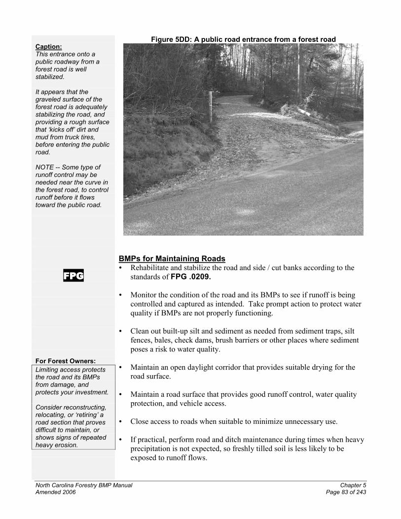
Caption:This entrance onto apublic roadway from aforest road is wellstabilized.
It appears that thegraveled surface of theforest road is adequatelystabilizing the road, andproviding a rough surfacethat ‘kicks off’ dirt andmud from truck tires,before entering the publicroad.
NOTE -- Some type ofrunoff control may beneeded near the curve inthe forest road, to controlrunoff before it flowstoward the public road.
FPGFPGFPGFPG
For Forest Owners:
Limiting access protectsthe road and its BMPsfrom damage, andprotects your investment.
Consider reconstructing,relocating, or ‘retiring’ aroad section that provesdifficult to maintain, orshows signs of repeatedheavy erosion.
Figure 5DD: A public road entrance from a forest road
BMPs for Maintaining Roads� Rehabilitate and stabilize the road and side / cut banks according to the
standards of FPG .0209.
� Monitor the condition of the road and its BMPs to see if runoff is beingcontrolled and captured as intended. Take prompt action to protect waterquality if BMPs are not properly functioning.
� Clean out built-up silt and sediment as needed from sediment traps, siltfences, bales, check dams, brush barriers or other places where sedimentposes a risk to water quality.
� Maintain an open daylight corridor that provides suitable drying for theroad surface.
� Maintain a road surface that provides good runoff control, water qualityprotection, and vehicle access.
� Close access to roads when suitable to minimize unnecessary use.
� If practical, perform road and ditch maintenance during times when heavyprecipitation is not expected, so freshly tilled soil is less likely to beexposed to runoff flows.

North Carolina Forestry BMP Manual Chapter 5Amended 2006 Page 84 of 243
FPGFPGFPGFPG
Caption:Note the BMPs on thisskid trail and streamcrossing:- Good use of leftoverlogging debris to mat theskid trail surface.
- Full-width, solid-surfacepanel stream crossingusing bridgemats.
- Skid trail width is kept toa minimum.
- Skid trail curves(background) as itapproaches the streamcrossing from upslope,creating a ‘break in thegrade’ before the stream.
Part 5 -- Skid Trails
Skid trails are pathways used to transport trees, logs, and other forest productsfrom the woods to a deck, landing or roadside. Skid trails are usually fortemporary use. However, if they are not constructed or used correctly, skidtrails can have long-lasting impacts on water quality and site conditions.
Rules Related to Skid Trails
Forest Practices Guidelines Related to Water Quality (FPGs)
North Carolina General Statute 77-13 and General Statute 77-14
DWQ riverbasin and watershed ‘Riparian Buffer Rules’
These ‘buffer rules’ for specific river basins and watersheds set limitations onskid trails within the 50-foot buffer zone.
North Carolina Dredge and Fill Law
This state law requires that permits be secured for discharges of dredged or fillmaterial in certain locations within the 20 Coastal Area Management Act(CAMA) counties. Refer to Chapter 6 for more information on this law.
Figure 5EE: A skid trail and stream crossing in Durham County, N.C.

North Carolina Forestry BMP Manual Chapter 5Amended 2006 Page 85 of 243
Caption:Note these BMPs --Skidding is going uphill,which allows for bettercontrol of runoff.
The skid trail curvesalong the slope contour,rather than simply straightup/down.
Skid trail width is kept to aminimum, despite thelong timber turning radius.
NOTE -- While the trailappears to be soft, thereare no intensive ruts,gouges or trenches thatmight funnel runoff.
Helpful Hints:
The BMPs offered in thisPart 4 may also besuitable for temporaryroads that are needed forforestry use. If a road islikely to becomepermanent, then it issuggested you use theBMPs provided in Part 3of this Chapter.
Minimizing the width ofskid trails is especiallyimportant on thinningsand other partial harvests.
A switchback, or zig-zagpattern, may be usefulwhen laying out skid trailsin steep terrain.
Figure 5FF: A curving skid trail in western North Carolina
BMPs for Skid Trails� Minimize disturbance to the soil such that surface runoff does not result in
sediment transport into waterbodies. Where conditions warrant:-- Concentrate skidding on as few skid trails as needed.-- Limit primary skid trails to 10 percent of the total working area.-- Avoid widespread or random skidding patterns with repeated passes.-- Minimize placement and use of skid trails in ephemeral drainages. If
skid trails must be within or cross an ephemeral drainage, additionalBMPs are needed to protect water quality.
-- Create skid trails only as wide as necessary to safely operate yourequipment and conduct the forestry operation. Avoid creating two-laneskid trails, which disturb more soil area.
-- Minimize the extent of gouges or trenches upon the ground surface thatare created by the skidding of trees or logs.
� On sloping terrain, skid trails should follow along the land contours andshould be kept to 25 percent grade or less when practical:-- If trails must be located on steeper slopes, more BMPs than usual are
needed to control and capture runoff to protect water quality.
� Install waterbars, brush barriers, turnouts or use other methods as neededto control and capture runoff.
� When forest management goals and site conditions warrant, frequentlypack down leftover logging debris atop primary skid trails to minimizefurther disturbance to exposed soils:

North Carolina Forestry BMP Manual Chapter 5Amended 2006 Page 86 of 243
Did You Know?
This debris is commonlycalled ‘slash’ or ‘laps.’
Did You Know?
Other names for decksinclude: landings, ramps,setouts and docks.
FPGFPGFPGFPG
FPGFPGFPGFPG
-- To be most effective, this should be done as the skidding is taking place,not simply after the job is completed. As the equipment operates on thedebris, it helps break down the debris with each pass.
-- Packing down logging debris is often an effective and affordable BMP toinstall at the approaches to stream crossings.
Part 6 -- Decks and Landings
Log decks are locations where trees, logs or other forest products are removedfrom the forest and temporarily placed so they can be loaded onto trucks andtransported from the job site. Because of the disturbance to exposed soil andrepeated equipment traffic in a concentrated area, decks have the potential toproduce significant runoff and erosion. As a result, there are rules thatdetermine certain actions and practices that must be undertaken to protectwater quality. These rules are noted below:
Rules Related to Decks and Landings
Forest Practices Guidelines Related to Water Quality (FPGs)
North Carolina General Statute 77-13 and General Statute 77-14
DWQ riverbasin and watershed ‘Riparian Buffer Rules’
These ‘buffer rules’ set limitations on the location of decks and landings.
North Carolina Dredge and Fill Law
This state law requires that permits be secured for discharges of dredged or fillmaterial in certain locations within the 20 Coastal Area Management Act(CAMA) counties. Refer to Chapter 6 for more information on this law.
BMPs for Decks & Landings� Minimize the number and size of decks.
� Establish decks at locations where soil disturbance is minimized.
� Site your deck with these factors in mind, as conditions allow:-- Outside of the SMZ. If a deck must be sited within the SMZ, read and
understand the requirements outlined within FPG .0201.-- Outside of ephemeral drainages.-- On flat terrain or gentle slopes.-- Upon stable soils.
� Control runoff and/or capture sediment that flows off of the deck site.
� During use of the deck, maintain groundcover materials on exposed baresoil areas that may pose a risk to accelerated erosion.

North Carolina Forestry BMP Manual Chapter 5Amended 2006 Page 87 of 243
For Forest Owners:
Deck locations shouldprovide the most efficientaccess for the site, tominimize the number thatare needed.
Consider using the BMPsin this Part 6 for portablein-woods sawmills,wood chippers,and debris processors.
Caption:This active logging deckhas some BMPs worthnoting:
- Flat terrain so runoff iseasier to control.
- Open sunny area topromote drying of the soilafter precipitation.
- Wooden road pallets /mats promote soilstabilization.
- Crushed gravelminimizes soildisturbance andprovides good tractionfor log trucks.
� If decks must be placed in steep terrain:-- Select side-ridge locations as high on the slope as practical, to provide
as much room as possible for controlling runoff and/or capturingsediment before it reaches a waterbody at the bottom of the slope.
-- Use more BMPs than usual to control runoff and capture sediment.
Figure 5GG: Active logging deck