north carolina pedestrian crossing guidance · north carolina pedestrian crossing guidance 1...
TRANSCRIPT
North Carolina Pedestrian Crossing
Guidance
NCDOT Project 2014‐15
FHWA/NC/2014‐15
July 2015
Bastian J. Schroeder, PhD, PE
Sarah Worth O’Brien
Daniel J. Findley, PhD, PE
Institute for Transportation Research and Education (ITRE)
North Carolina State University

North Carolina Pedestrian Crossing Guidance
‐ This page intentionally left blank ‐
North Carolina Department of Transportation Research Project No. 2014‐15
North Carolina Pedestrian Crossing Guidance
Bastian J. Schroeder, Ph.D, P.E.Sarah Worth O’Brien Daniel J. Findley, Ph.D, P.E.
FHWA/NC/2014‐15

North Carolina Pedestrian Crossing Guidance
‐ This page intentionally left blank ‐
North Carolina Pedestrian Crossing Guidance i
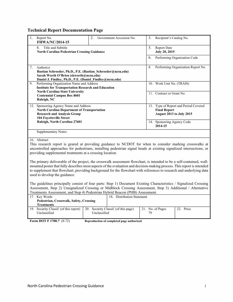
Technical Report Documentation Page
1. Report No. FHWA/NC/2014-15
2. Government Accession No.
3. Recipient’s Catalog No.
4. Title and Subtitle North Carolina Pedestrian Crossing Guidance
5. Report Date July 20, 2015
6. Performing Organization Code
7. Author(s) Bastian Schroeder, Ph.D., P.E. ([email protected]) Sarah Worth O’Brien ([email protected]) Daniel J. Findley, Ph.D., P.E. ([email protected])
8. Performing Organization Report No.
9. Performing Organization Name and Address Institute for Transportation Research and Education North Carolina State University Centennial Campus Box 8601 Raleigh, NC
10. Work Unit No. (TRAIS)
11. Contract or Grant No.
12. Sponsoring Agency Name and Address North Carolina Department of Transportation Research and Analysis Group 104 Fayetteville Street Raleigh, North Carolina 27601
13. Type of Report and Period Covered Final Report August 2013 to July 2015
14. Sponsoring Agency Code 2014-15
Supplementary Notes:
16. Abstract This research report is geared at providing guidance to NCDOT for when to consider marking crosswalks at uncontrolled approaches for pedestrians, installing pedestrian signal heads at existing signalized intersections, or providing supplemental treatments at a crossing location. The primary deliverable of the project, the crosswalk assessment flowchart, is intended to be a self-contained, wall-mounted poster that fully describes most aspects of the evaluation and decision-making process. This report is intended to supplement that flowchart, providing background for the flowchart with references to research and underlying data used to develop the guidance. The guidelines principally consist of four parts: Step 1) Document Existing Characteristics / Signalized Crossing Assessment, Step 2) Unsignalized Crossing or Midblock Crossing Assessment, Step 3) Additional / Alternative Treatments Assessment, and Step 4) Pedestrian Hybrid Beacon (PHB) Assessment. 17. Key Words
Pedestrian, Crosswalk, Safety, Crossing Treatments
18. Distribution Statement
19. Security Classif. (of this report) Unclassified
20. Security Classif. (of this page) Unclassified
21. No. of Pages 79
22. Price
Form DOT F 1700.7 (8-72) Reproduction of completed page authorized
North Carolina Pedestrian Crossing Guidance ii
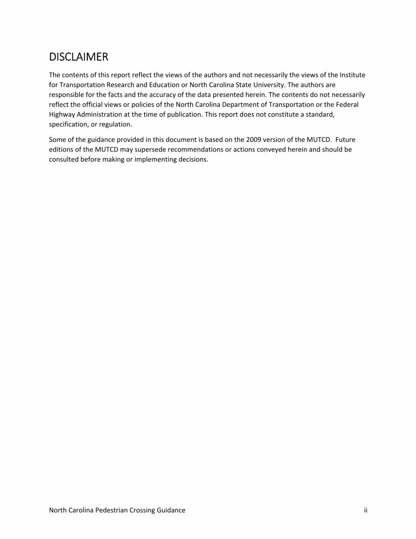
DISCLAIMER
The contents of this report reflect the views of the authors and not necessarily the views of the Institute for Transportation Research and Education or North Carolina State University. The authors are responsible for the facts and the accuracy of the data presented herein. The contents do not necessarily reflect the official views or policies of the North Carolina Department of Transportation or the Federal Highway Administration at the time of publication. This report does not constitute a standard, specification, or regulation.
Some of the guidance provided in this document is based on the 2009 version of the MUTCD. Future editions of the MUTCD may supersede recommendations or actions conveyed herein and should be consulted before making or implementing decisions.
North Carolina Pedestrian Crossing Guidance iii
ACKNOWLEDGEMENTS
The research team appreciates the North Carolina Department of Transportation for the support and funding of this project. We extend our thanks to the project Steering and Implementation Committee members:
Scott Cole, P.E., P.L.S. ‐ Chair Joel C. Cranford D.D. (Bucky) Galloway, P.E. Steven J. Hamilton, P.E., CPM W.L. (Lee) Jernigan, P.E. Ernest Morrison, P.E. Kumar Trivedi, P.E. Terry M. Hopkins, P.E. Dale Stokes Anthony D. Wyatt, P.E., PTOE Robert J. Ziemba, P.E.
The authors especially thank those who were instrumental in assisting with the project. These individuals included staff from Asheville, Cary, Charlotte, Durham, Fayetteville, Greensboro, Raleigh, Wilmington, and Winston‐Salem and NCDOT personnel who participated in our interviews: Jason Davidson, Jeff Cabaniss, George Eckart, Andy Brown, Al Grandy, Frank West, Dawn McPherson, David Willett, JP Couch, Sean Epperson, Daniel Adams, Patrick Norman, Anna Henderson, Scott Cook, Ken Putnam, John Sandor, Don Bennett, David Spencer, Philip Loziuk, Chris Spencer, Debbie Self, Connie James, and Matthew Burczyk. We also want to thank State Traffic Engineer Kevin Lacy, Division Traffic Engineers, Regional Traffic Engineers, and Division Operations Engineers from NCDOT, and Ken Putnam and Barb Mee from Asheville for reviewing, testing, and providing comment on draft versions of the flowchart, which greatly helped to improve the end result. Additionally, acknowledgement goes to Melissa Barnes with Minnesota DOT and Bill Cowern with the City of Boulder, CO for sharing insight on their agencies’ decision making processes and lessons learned through implementation of their pedestrian crossing guidelines.

North Carolina Pedestrian Crossing Guidance iv
‐ This page intentionally left blank ‐
North Carolina Pedestrian Crossing Guidance v
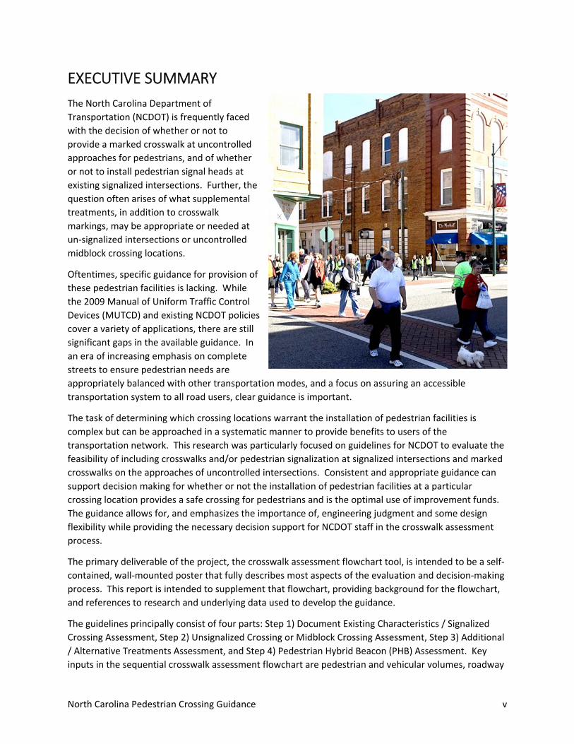
EXECUTIVE SUMMARY
The North Carolina Department of Transportation (NCDOT) is frequently faced with the decision of whether or not to provide a marked crosswalk at uncontrolled approaches for pedestrians, and of whether or not to install pedestrian signal heads at existing signalized intersections. Further, the question often arises of what supplemental treatments, in addition to crosswalk markings, may be appropriate or needed at un‐signalized intersections or uncontrolled midblock crossing locations.
Oftentimes, specific guidance for provision of these pedestrian facilities is lacking. While the 2009 Manual of Uniform Traffic Control Devices (MUTCD) and existing NCDOT policies cover a variety of applications, there are still significant gaps in the available guidance. In an era of increasing emphasis on complete streets to ensure pedestrian needs are appropriately balanced with other transportation modes, and a focus on assuring an accessible transportation system to all road users, clear guidance is important.
The task of determining which crossing locations warrant the installation of pedestrian facilities is complex but can be approached in a systematic manner to provide benefits to users of the transportation network. This research was particularly focused on guidelines for NCDOT to evaluate the feasibility of including crosswalks and/or pedestrian signalization at signalized intersections and marked crosswalks on the approaches of uncontrolled intersections. Consistent and appropriate guidance can support decision making for whether or not the installation of pedestrian facilities at a particular crossing location provides a safe crossing for pedestrians and is the optimal use of improvement funds. The guidance allows for, and emphasizes the importance of, engineering judgment and some design flexibility while providing the necessary decision support for NCDOT staff in the crosswalk assessment process.
The primary deliverable of the project, the crosswalk assessment flowchart tool, is intended to be a self‐contained, wall‐mounted poster that fully describes most aspects of the evaluation and decision‐making process. This report is intended to supplement that flowchart, providing background for the flowchart, and references to research and underlying data used to develop the guidance.
The guidelines principally consist of four parts: Step 1) Document Existing Characteristics / Signalized Crossing Assessment, Step 2) Unsignalized Crossing or Midblock Crossing Assessment, Step 3) Additional / Alternative Treatments Assessment, and Step 4) Pedestrian Hybrid Beacon (PHB) Assessment. Key inputs in the sequential crosswalk assessment flowchart are pedestrian and vehicular volumes, roadway

North Carolina Pedestrian Crossing Guidance vi
cross‐section and design attributes, and vehicular speed, as well as various other considerations. The potential outcomes of the assessment process include recommendations for marking crosswalks, installing supplemental treatments, warranting signal or pedestrian hybrid beacon installation, as well as cases where no action is required. Throughout the process, all guidance for marking crosswalks and treatment installations are subject to the availability of funds to install and maintain the treatment.
The development of the guidelines was accomplished through the following tasks including a review of literature; survey of NCDOT, municipal, and state practices; compilation of literature and survey findings; and refinement of the process through collaboration with NCDOT. These research findings will guide future installations of pedestrian treatments with a consistent, repeatable process that will provide a safety benefit for users of the transportation network in North Carolina. While this report focuses towards NCDOT practices, it may serve as guidance for municipalities in North Carolina and perhaps outside the state as well.
North Carolina Pedestrian Crossing Guidance vii
Table of Contents
DISCLAIMER .................................................................................................................. II
ACKNOWLEDGEMENTS ............................................................................................... III
EXECUTIVE SUMMARY ................................................................................................. V
0 INTRODUCTION ..................................................................................................... 1
0.1 Evaluate Crossings by Approach ................................................................................................... 1
0.2 General Principles and Considerations ......................................................................................... 1
0.3 Inappropriate Use of Guidance ..................................................................................................... 3
0.4 When to Use the Guidance ........................................................................................................... 3
0.5 Overview of Process Steps ............................................................................................................ 3
1 STEP 1: DOCUMENT EXISTING CHARACTERISTICS / SIGNALIZED CROSSING
ASSESSMENT ................................................................................................................ 5
1.1 Gather Relevant Data .................................................................................................................... 7
1.2 Check for Presence of Existing or Planned ADA Compliant Path .................................................. 7
1.3 Check Crossing Type ...................................................................................................................... 8
1.3.1 Unsignalized Intersection or Mid‐block Crossing Type ......................................................... 9
1.3.2 Signalized Intersection Type ................................................................................................. 9
2 STEP 2: UNSIGNALIZED / MID‐BLOCK CROSSING ASSESSMENT ......................... 13
2.1 Check Number of Lanes .............................................................................................................. 15
2.2 Check Posted Speed or Operating Speed ................................................................................... 16
2.2.1 On Two‐Lane Roads ............................................................................................................ 16
2.2.2 On Three‐Lane Roads or Four‐or‐More‐Lane Roads with a Raised Median ....................... 17
2.2.3 On Four‐or‐More‐Lane Roads without a Raised Median .................................................... 17
2.3 Check Vehicle Volume ................................................................................................................. 17
2.3.1 On Two‐Lane Roads, 35 mph .............................................................................................. 18
2.3.2 On Three‐Lane Roads or Four‐or‐More‐Lane Roads with a Raised Median, 30 mph or Less 18
2.3.3 On Three‐Lane Roads or Four‐or‐More‐Lane Roads with a Raised Median, 35 mph ......... 18
2.3.4 On Four‐or‐More‐Lane Roads without a Raised Median, 30 mph or Less ......................... 18
2.4 Check Pedestrian Volume ........................................................................................................... 19

North Carolina Pedestrian Crossing Guidance viii
3 STEP 3: ADDITIONAL / ALTERNATIVE TREATMENTS ASSESSMENT ..................... 21
3.1 Check Speed ................................................................................................................................ 23
3.2 Check Peak‐Hour Pedestrian Volume ......................................................................................... 23
3.2.1 On Road with Speed 35 mph or Less .................................................................................. 24
3.2.2 On Road with Speed Greater than 35 mph ......................................................................... 24
3.3 Check MUTCD Warrants 4 or 5 ................................................................................................... 24
3.4 Check Pedestrian Delay ............................................................................................................... 27
3.4.1 On Road with Speed 35 mph or Less .................................................................................. 28
3.4.2 On Road with Speed Greater than 35 mph ......................................................................... 29
3.4.3 Quick Reference Charts to Estimate Total Pedestrian Delay .............................................. 29
4 STEP 4: PEDESTRIAN HYBRID BEACON ASSESSMENT .......................................... 31
4.1 Check Speed ................................................................................................................................ 33
4.2 Check crosswalk Length, Vehicle & Pedestrian Volumes ............................................................ 33
4.2.1 On Road with Speed Less Than or Equal to 35 mph ........................................................... 33
4.2.2 On Road with Speed Greater than 35 mph ......................................................................... 33
5 REFERENCES......................................................................................................... 35
APPENDIX A. COMMON RESOURCES LIST .............................................................. 39
APPENDIX B. EXCERPTS FROM THE 2009 MUTCD ................................................. 47
APPENDIX C. TOTAL PEDESTRIAN DELAY CHARTS ................................................. 68
APPENDIX D. LITERATURE REVIEW AND STATE OF THE PRACTICE ........................ 75
D.1 State of the Practice .................................................................................................................... 77
D.2 North Carolina Highway Divisions ............................................................................................... 77
D.3 Large North Carolina Municipalities ........................................................................................... 78
D.4 Other States ................................................................................................................................ 79
D.4.1 Minnesota Department of Transportation ......................................................................... 79
D.4.2 City of Boulder, Colorado .................................................................................................... 80
D.5 Appendix References .................................................................................................................. 81
North Carolina Pedestrian Crossing Guidance 1
Pedestrian Crossing Guidance
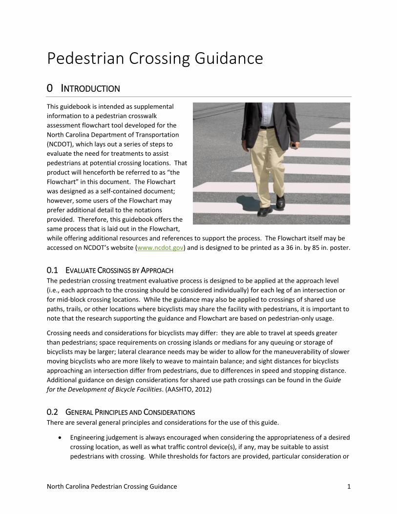
0 INTRODUCTION
This guidebook is intended as supplemental
information to a pedestrian crosswalk
assessment flowchart tool developed for the
North Carolina Department of Transportation
(NCDOT), which lays out a series of steps to
evaluate the need for treatments to assist
pedestrians at potential crossing locations. That
product will henceforth be referred to as “the
Flowchart” in this document. The Flowchart
was designed as a self-contained document;
however, some users of the Flowchart may
prefer additional detail to the notations
provided. Therefore, this guidebook offers the
same process that is laid out in the Flowchart,
while offering additional resources and references to support the process. The Flowchart itself may be
accessed on NCDOT’s website (www.ncdot.gov) and is designed to be printed as a 36 in. by 85 in. poster.
0.1 EVALUATE CROSSINGS BY APPROACH The pedestrian crossing treatment evaluative process is designed to be applied at the approach level
(i.e., each approach to the crossing should be considered individually) for each leg of an intersection or
for mid-block crossing locations. While the guidance may also be applied to crossings of shared use
paths, trails, or other locations where bicyclists may share the facility with pedestrians, it is important to
note that the research supporting the guidance and Flowchart are based on pedestrian-only usage.
Crossing needs and considerations for bicyclists may differ: they are able to travel at speeds greater
than pedestrians; space requirements on crossing islands or medians for any queuing or storage of
bicyclists may be larger; lateral clearance needs may be wider to allow for the maneuverability of slower
moving bicyclists who are more likely to weave to maintain balance; and sight distances for bicyclists
approaching an intersection differ from pedestrians, due to differences in speed and stopping distance.
Additional guidance on design considerations for shared use path crossings can be found in the Guide
for the Development of Bicycle Facilities. (AASHTO, 2012)
0.2 GENERAL PRINCIPLES AND CONSIDERATIONS There are several general principles and considerations for the use of this guide.
Engineering judgement is always encouraged when considering the appropriateness of a desired
crossing location, as well as what traffic control device(s), if any, may be suitable to assist
pedestrians with crossing. While thresholds for factors are provided, particular consideration or
North Carolina Pedestrian Crossing Guidance 2
additional study may be necessary for sites near threshold values, or where special
circumstances or special populations are present.
Field investigations are strongly recommended to confirm site characteristics and input data,
and to observe pedestrian and driver behaviors. In some cases, field visits may be required to
collect data needed to move through the crossing treatment evaluation process.
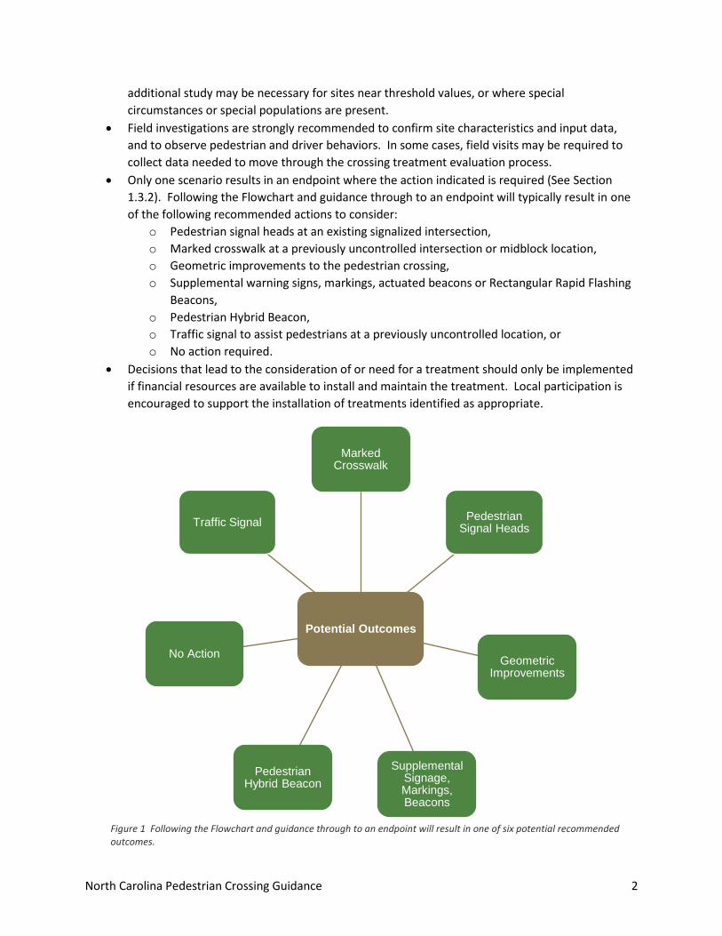
Only one scenario results in an endpoint where the action indicated is required (See Section
1.3.2). Following the Flowchart and guidance through to an endpoint will typically result in one
of the following recommended actions to consider:
o Pedestrian signal heads at an existing signalized intersection,
o Marked crosswalk at a previously uncontrolled intersection or midblock location,
o Geometric improvements to the pedestrian crossing,
o Supplemental warning signs, markings, actuated beacons or Rectangular Rapid Flashing
Beacons,
o Pedestrian Hybrid Beacon,
o Traffic signal to assist pedestrians at a previously uncontrolled location, or
o No action required.
Decisions that lead to the consideration of or need for a treatment should only be implemented
if financial resources are available to install and maintain the treatment. Local participation is
encouraged to support the installation of treatments identified as appropriate.
Potential Outcomes
Marked Crosswalk
Pedestrian Signal Heads
Geometric Improvements
Supplemental Signage, Markings, Beacons
Pedestrian Hybrid Beacon
No Action
Traffic Signal
Figure 1 Following the Flowchart and guidance through to an endpoint will result in one of six potential recommended outcomes.

North Carolina Pedestrian Crossing Guidance 3
0.3 INAPPROPRIATE USE OF GUIDANCE The pedestrian crossing treatment evaluative process is not intended to be used to prioritize sidewalk
improvements or to evaluate the connectivity of a pedestrian network. National Cooperative Highway
Research Program Report 803 Pedestrian and Bicycle Transportation along Existing Roads – ActiveTrans
Priority Tool Guidebook provides a methodology and tool to assist agencies in evaluating and prioritizing
the need to provide or improve facilities for active travelers, (Lagerwey, Hintze, Elliott, Toole, &
Schneider, 2015)
Crossing locations within school zones or along school walking routes are a specialized type of crossing
that may require additional considerations. Therefore, school-related crossing evaluations are outside
the scope of this crossing treatment evaluative process.
Crossing locations called to the Department’s attention through a written request for reasonable access
under the Americans with Disabilities Act (ADA) should not be evaluated using this guide or Flowchart.1
ADA requests follow a different process established through the “Standard Practice for Pedestrian
Reasonable Access requests from Pedestrians with Qualifying Disabilities under the Americans with
Disabilities Act.” (NCDOT, 2009)
0.4 WHEN TO USE THE GUIDANCE The pedestrian crossing treatment evaluation process may be prompted through a variety of
mechanisms. Most commonly, it is expected that the Department will initiate an evaluation of a
crossing location at the request of a municipality or citizen. Pedestrian crash hot spot locations
identified through crash analyses may also trigger an investigation for alternative or additional crossing
treatments using the Flowchart as a means to mitigate possible crash factors. As local agencies develop
pedestrian or greenway plans, it may be beneficial to review crossing locations identified and prioritized
through the planning process to better evaluate infrastructure needs and develop useful cost estimates.
While it is more likely that this evaluation process will be performed in response to a particular request
or prioritized location, it could also be utilized as a proactive means to systematically review existing
crossing locations as part of a basic needs assessment and inventory. It is possible to envelop the
Flowchart as a component within established operations and maintenance assessment workflows
currently implemented in the Department.
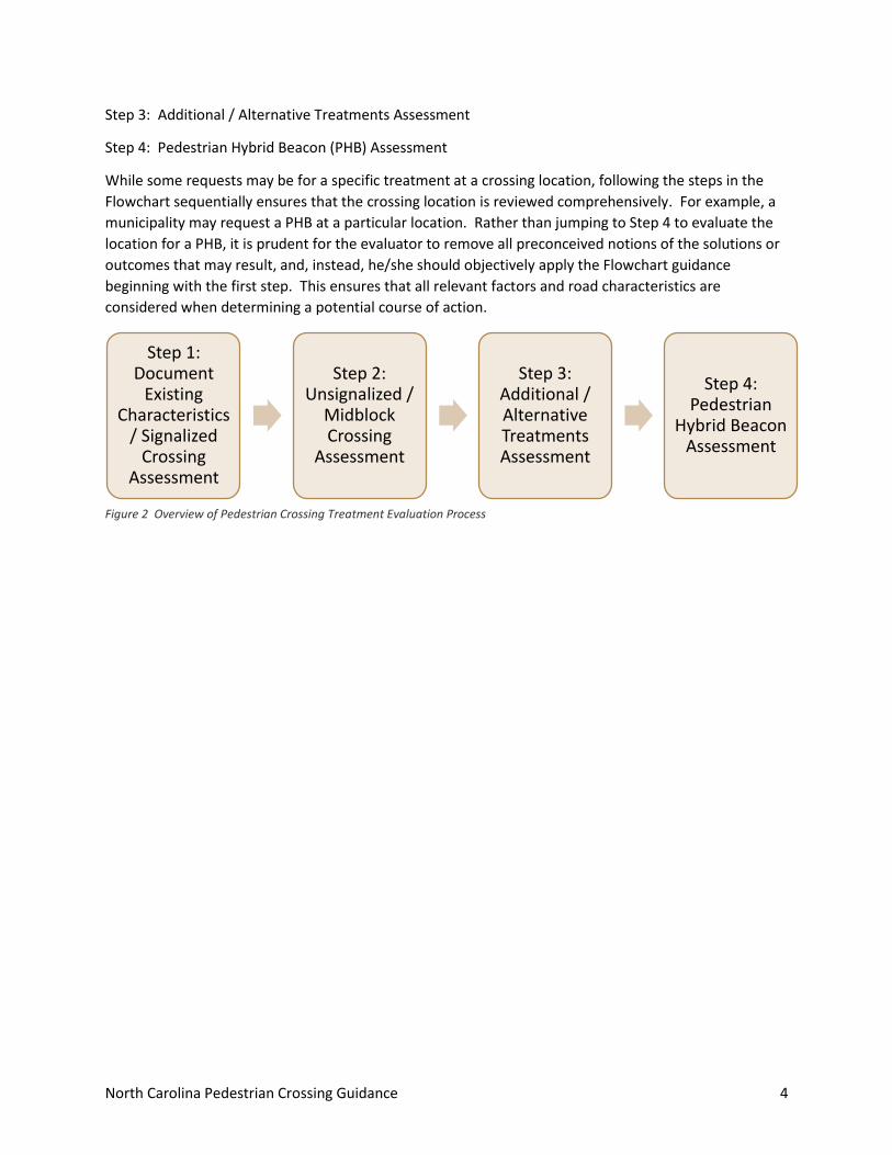
0.5 OVERVIEW OF PROCESS STEPS There are four main steps to move through when evaluating a pedestrian crossing. These steps are
intended to be performed in sequential order:
Step 1: Document Existing Characteristics / Signalized Crossing Assessment
Step 2: Unsignalized Crossing or Midblock Crossing Assessment
1 ADA compliance for equivalent facilitation only applies to locations with existing pedestrian facilities. Crosswalks constitute distinct elements of the right-of-way intended to facilitate pedestrian traffic, and as such, they must comply with ADA regulations when installed or resurfaced. Resurfacing of a crosswalk requires the provision of curb ramps at that crosswalk. (DOJ/DOT, 2013)
North Carolina Pedestrian Crossing Guidance 4
Step 3: Additional / Alternative Treatments Assessment
Step 4: Pedestrian Hybrid Beacon (PHB) Assessment
While some requests may be for a specific treatment at a crossing location, following the steps in the
Flowchart sequentially ensures that the crossing location is reviewed comprehensively. For example, a
municipality may request a PHB at a particular location. Rather than jumping to Step 4 to evaluate the
location for a PHB, it is prudent for the evaluator to remove all preconceived notions of the solutions or
outcomes that may result, and, instead, he/she should objectively apply the Flowchart guidance
beginning with the first step. This ensures that all relevant factors and road characteristics are
considered when determining a potential course of action.
Step 1: Document
Existing Characteristics
/ Signalized Crossing
Assessment
Step 2: Unsignalized /
Midblock Crossing
Assessment
Step 3: Additional / Alternative Treatments Assessment
Step 4: Pedestrian
Hybrid Beacon Assessment
Figure 2 Overview of Pedestrian Crossing Treatment Evaluation Process
North Carolina Pedestrian Crossing Guidance 5
1 STEP 1: DOCUMENT EXISTING CHARACTERISTICS / SIGNALIZED CROSSING
ASSESSMENT
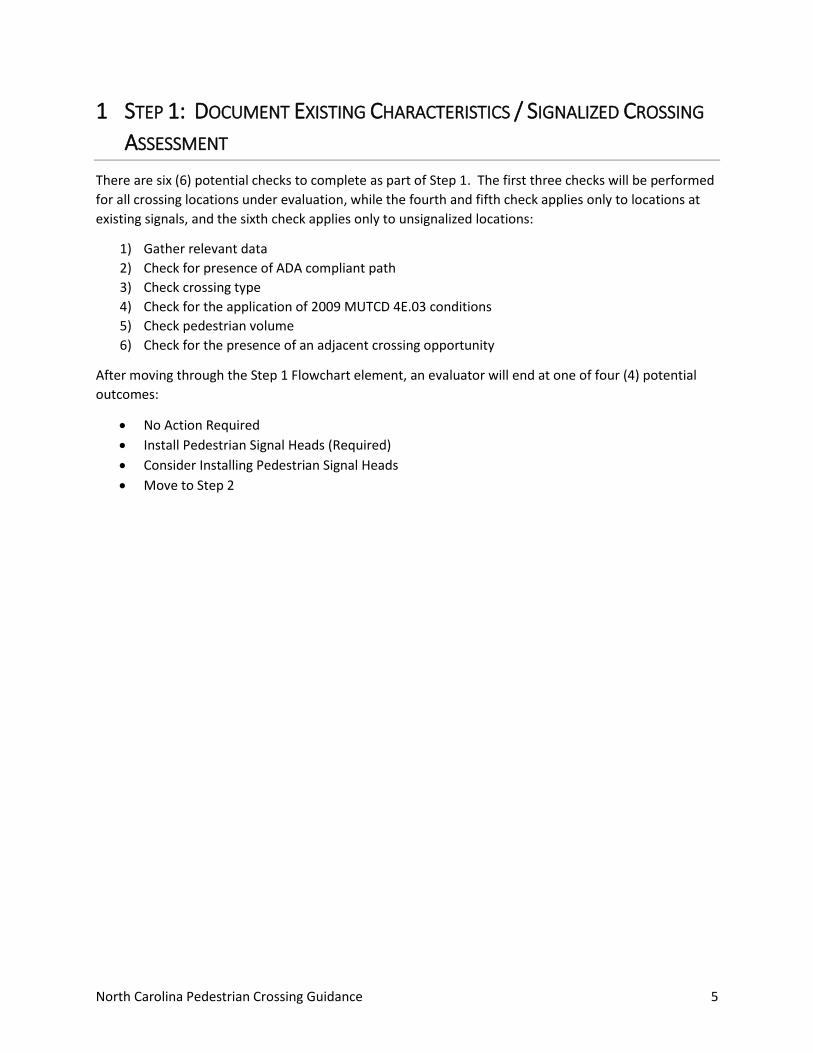
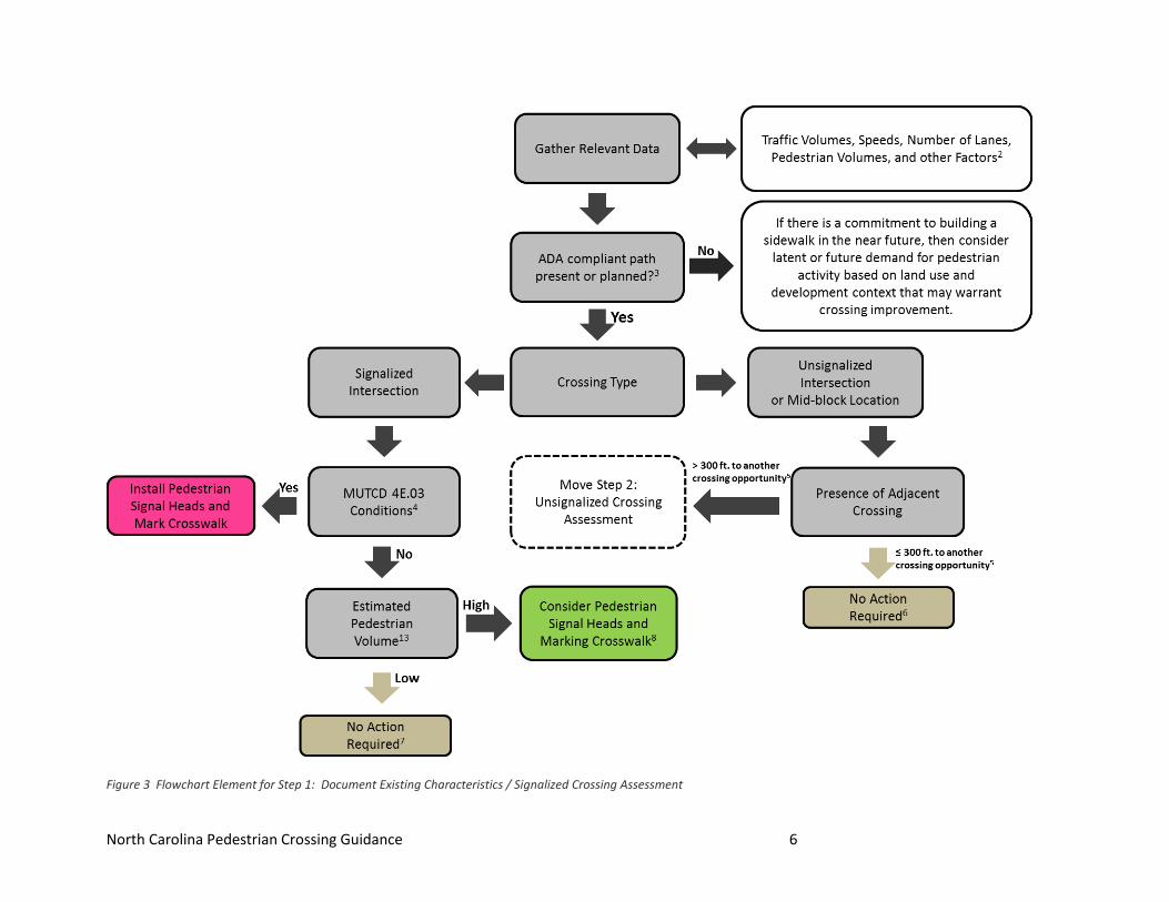
There are six (6) potential checks to complete as part of Step 1. The first three checks will be performed
for all crossing locations under evaluation, while the fourth and fifth check applies only to locations at
existing signals, and the sixth check applies only to unsignalized locations:
1) Gather relevant data
2) Check for presence of ADA compliant path
3) Check crossing type
4) Check for the application of 2009 MUTCD 4E.03 conditions
5) Check pedestrian volume
6) Check for the presence of an adjacent crossing opportunity
After moving through the Step 1 Flowchart element, an evaluator will end at one of four (4) potential
outcomes:
No Action Required
Install Pedestrian Signal Heads (Required)
Consider Installing Pedestrian Signal Heads
Move to Step 2
North Carolina Pedestrian Crossing Guidance 6
Figure 3 Flowchart Element for Step 1: Document Existing Characteristics / Signalized Crossing Assessment
North Carolina Pedestrian Crossing Guidance 7
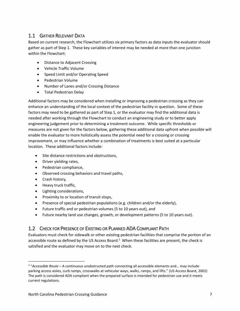
1.1 GATHER RELEVANT DATA Based on current research, the Flowchart utilizes six primary factors as data inputs the evaluator should
gather as part of Step 1. These key variables of interest may be needed at more than one junction
within the Flowchart:
Distance to Adjacent Crossing
Vehicle Traffic Volume
Speed Limit and/or Operating Speed
Pedestrian Volume
Number of Lanes and/or Crossing Distance
Total Pedestrian Delay
Additional factors may be considered when installing or improving a pedestrian crossing as they can
enhance an understanding of the local context of the pedestrian facility in question. Some of these
factors may need to be gathered as part of Step 1, or the evaluator may find the additional data is
needed after working through the Flowchart to conduct an engineering study or to better apply
engineering judgement prior to determining a treatment outcome. While specific thresholds or
measures are not given for the factors below, gathering these additional data upfront when possible will
enable the evaluator to more holistically assess the potential need for a crossing or crossing
improvement, or may influence whether a combination of treatments is best suited at a particular
location. These additional factors include:
Site distance restrictions and obstructions,
Driver yielding rates,
Pedestrian compliance,
Observed crossing behaviors and travel paths,
Crash history,
Heavy truck traffic,
Lighting considerations,
Proximity to or location of transit stops,
Presence of special pedestrian populations (e.g. children and/or the elderly),
Future traffic and or pedestrian volumes (5 to 10 years out), and
Future nearby land use changes, growth, or development patterns (5 to 10 years out).
1.2 CHECK FOR PRESENCE OF EXISTING OR PLANNED ADA COMPLIANT PATH Evaluators must check for sidewalk or other existing pedestrian facilities that comprise the portion of an
accessible route as defined by the US Access Board.2 When these facilities are present, the check is
satisfied and the evaluator may move on to the next check.
2 “Accessible Route – A continuous unobstructed path connecting all accessible elements and… may include parking access aisles, curb ramps, crosswalks at vehicular ways, walks, ramps, and lifts.” (US Access Board, 2002) The path is considered ADA compliant when the prepared surface is intended for pedestrian use and it meets current regulations.
North Carolina Pedestrian Crossing Guidance 8
If pedestrian facilities are not present, the evaluator should consult with the local agency to determine if
there are plans to build them in the near future.3 For locations where agencies demonstrate a firm
commitment to provide a sidewalk and secure the funds to do so within the next five (5) years, the
evaluator can proceed with the crossing assessment, as this check is satisfied.
If facilities are not present and there are no plans to install them, the check is not satisfied and the
evaluator halts progress through the Flowchart. However, this does not mean that the original request
for crossing assistance is without merit. Evaluators should consider pedestrian activity at the potential
crossing location and within 150 feet of either side of the location. If there is sufficient pedestrian
activity or indications of latent or future demand based on land use and development context, the
Department may consider initiating a separate project development process with the local agency
outside the scope of the Flowchart process to discern the feasibility of constructing an ADA compliant
path, and then reevaluate the crosswalk configuration at that time.
1.3 CHECK CROSSING TYPE Simply put, the evaluator indicates whether the crossing location is at a signalized or unsignalized
location. This decision point in the Flowchart determines the type of crossing assessment to apply. For
signalized intersections, evaluators will complete Step 1. Unsignalized or midblock locations will be
further assessed through Steps 2, 3, and 4 of the Flowchart.
3 This guidance is aligned with a memorandum on alternate curb ramp designs, which states, “during the preliminary engineering design, if an entity expresses a firm comment to provide sidewalks in the near future of completing a project, curb ramps can be shown on the pavement marking plans provided by the Signing and Delineation Unit.” (Lacy, 2011)
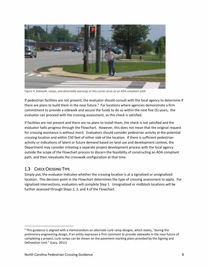
Figure 4 Sidewalk, ramps, and detectable warnings at this corner serve as an ADA compliant path.
North Carolina Pedestrian Crossing Guidance 9
1.3.1 Unsignalized Intersection or Mid-block Crossing Type
For locations that are unsignalized, evaluators must first consider the proximity of the potential crossing
to adjacent existing crossings.
If the potential crossing is less than or equal to 300 feet to another unsignalized crossing
opportunity, or less than 400 feet to a signalized intersection, then No Action is required.4 The
evaluator should confirm that the existing nearby crossing location can sufficiently meet
pedestrian needs. If observed pedestrian activity reveals that they do not use the existing
crossing location, further
investigation may be needed to
assess the existing crossing
opportunity. In some cases, the
existing adjacent crossing may
need to be improved and/or
enhanced with landscaping or
other positive guidance to
encourage and direct pedestrians
to cross at the existing location.
Engineering judgement should be
used for unique circumstances
where closely spaced crosswalks
may be needed due to pedestrian
activity.
If the potential crossing is greater than 300 feet to another unsignalized crossing opportunity, or
greater than 400 feet to a signalized intersection5, then the evaluator moves to Step 2 in the
Flowchart for further assessment.
1.3.2 Signalized Intersection Type
If the crossing type is at a signalized location, then the crossing is evaluated for the need for pedestrian
signal heads. Where the crosswalk is not currently marked, if the decision is made to install pedestrian
signal heads, the crosswalk should also be marked.6
Two checks are performed as part of the Signalized Crossing Assessment. The crossing is first checked to
determine if pedestrian signal heads are required, per 2009 MUTCD 4E.03. If not, then the estimated
4 From section 4D.01.06 of the MUTCD, “Midblock crosswalks shall not be signalized if they are located within 300 feet from the nearest traffic control signal, unless the proposed traffic control signal will not restrict the progressive movement of traffic.” Additional guidance is given that midblock crossings should not be signalized if located within 100 feet from STOP or YIELD controlled side streets or driveways. (Federal Highway Administration, 2009) 5 The NCDOT clarified that “mid-block crosswalks should not be located within 300 feet of a non-signalized intersection and 400 feet of a signalized intersection, as to not interfere with the functionality of the intersection.” (NCDOT, 2008) This standard practice guidance is irrespective of whether the mid-block crossing will be signalized. 6 Use engineering judgment based on location context to determine what type of pattern is most appropriate. High-visibility markings may be appropriate for school crosswalks or where pedestrians or marked crosswalks may not be expected by drivers. (National Committee on Uniform Traffic Control Devices, 2011)
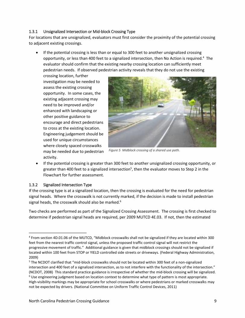
Figure 5 Midblock crossing of a shared use path.

North Carolina Pedestrian Crossing Guidance 10
pedestrian volume is checked. It is also recommended to consider pedestrian signal head installations
where:
The estimated pedestrian volume is above a specified “low volume” threshold discussed below,
To be consistent with adjacent intersections (e.g. in a downtown area), or
Where they may otherwise enhance pedestrian safety.
1.3.2.1 Check for 2009 MUTCD 4E.03 Conditions
At a signalized crossing location, the evaluator must review the crossing to determine if it meets
any of the conditions listed in 4E.03 of the MUTCD:
01 Pedestrian signal heads shall be used in conjunction with vehicular traffic control signals under any of the following conditions: A. If a traffic control signal is justified by an engineering study and meets either Warrant 4,
Pedestrian Volume or Warrant 5, School Crossing (see Chapter 4C); B. If an exclusive signal phase is provided or made available for pedestrian movements in one
or more directions, with all conflicting vehicular movements being stopped; C. At an established school crossing at any signalized location; or D. Where engineering judgment determines that multi-phase signal indications (as with split-
phase timing) would tend to confuse or cause conflicts with pedestrians using a crosswalk guided only by vehicular signal indications. (Federal Highway Administration, 2009)
If the crossing meets any of items A
through D, then the standard
requires that pedestrian signal heads
be installed. Installed pedestrian
signal heads should conform to
MUTCD’s guidance on signal timing
to provide sufficient pedestrian
clearance times for crossing. See
Section 4E.06 of the 2009 MUTCD for
further details.
1.3.2.2 Check Estimated Pedestrian Volume
In most cases, existing pedestrian volume data will be sparse. Therefore, two primary options
are available to gather such data: 1) conduct an observational study or 2) estimate volume using
proxy measures.
If the evaluator elects to conduct a study, the following is recommended to gather pedestrian
counts:
Seven continuous days of counts are preferred, when possible. Where resources are not
available to collect a week’s worth of data, a minimum of one weekend and one weekday
Figure 6 Protective-permissive left turn signals may be confusing to pedestrians attempting to rely on the vehicular traffic signals to know when it is their turn to cross, and therefore engineering judgement must determine whether Section 1.3.2.1 D of the 2009 MUTCD applies.
North Carolina Pedestrian Crossing Guidance 11
should be collected. The days of the week selected should target when the highest
pedestrian activity is expected.7
Restricting data collection to during daylight hours only is acceptable unless the land use
context around the site suggests that nighttime pedestrian activity should be expected.
Counts at the potential crossing location under study should include pedestrians that
cross within 150 feet of either side of the crossing.
Coordinate effort with the Division of Bicycle and Pedestrian Transportation for feedback
on additional or unique site-specific considerations prior to conducting the study, and to
obtain guidance on data collection protocols for pedestrian studies.
When observational data does not exist and will not be collected, proxy measures can be
estimated based on land use context and are sufficient to estimate pedestrian volume at a
crossing. Crossings that are near pedestrian trip generators or destinations, or those that may
connect complementary land uses should be considered for enhancement. Where proxy
measures are used, they should be well documented in the evaluator’s assessment.
Because existing pedestrian volume data is limited, the evaluator must use engineering
judgement to choose the appropriate low volume threshold from the following considerations:
The crossing area has less than 25 pedestrians per pedestrian peak hour OR less than 100
pedestrians per day.
At mid-block locations only: crossing area has less than 25 pedestrians per pedestrian
peak hour for at least four hours. (NCDOT, 2008)
The crossing area is not near high pedestrian trip generators.
The crossing area does not connect complementary land uses.
Lower volume thresholds may be considered for crossings with a significant presence of a
special population, such as children or the elderly. Where the estimated pedestrian volume is
considered low, no action is required.
7Bicycle and pedestrian volumes are lower and more variable due to weather (e.g., temperature and precipitation) and other factors than motor vehicle traffic. Therefore, it is more difficult to calculate AADT from shorter durations than seven days. (Nordback, Marshall, Janson, & Stolz, 2013) The Traffic Monitoring Guide suggests a 7 day duration, noting that “depending on several other factors…the preferred duration of automatic counts could be as long as 14 days.” If manual observers are used to collect the counts due to resource limitations, a 12-hour count is preferred. (Federal Highway Administration, 2013)
North Carolina Pedestrian Crossing Guidance 12
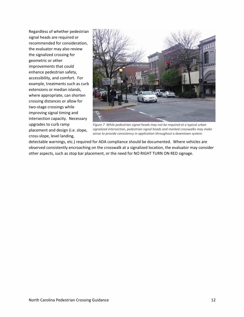
Regardless of whether pedestrian
signal heads are required or
recommended for consideration,
the evaluator may also review
the signalized crossing for
geometric or other
improvements that could
enhance pedestrian safety,
accessibility, and comfort. For
example, treatments such as curb
extensions or median islands,
where appropriate, can shorten
crossing distances or allow for
two-stage crossings while
improving signal timing and
intersection capacity. Necessary
upgrades to curb ramp
placement and design (i.e. slope,
cross-slope, level landing,
detectable warnings, etc.) required for ADA compliance should be documented. Where vehicles are
observed consistently encroaching on the crosswalk at a signalized location, the evaluator may consider
other aspects, such as stop bar placement, or the need for NO RIGHT TURN ON RED signage.
Figure 7 While pedestrian signal heads may not be required at a typical urban signalized intersection, pedestrian signal heads and marked crosswalks may make sense to provide consistency in application throughout a downtown system.
North Carolina Pedestrian Crossing Guidance 13
2 STEP 2: UNSIGNALIZED / MID-BLOCK CROSSING ASSESSMENT
There are four (4) potential checks to complete as part of Step 2:
1) Check the number of lanes
2) Check posted or operating speed
3) Check vehicular traffic volume
4) Check pedestrian volume
After moving through the Step 2 Flowchart element, an evaluator will end at one of three (3) potential
outcomes:
No Action Required
Consider Marking Crosswalk
Move to Step 3
North Carolina Pedestrian Crossing Guidance 14
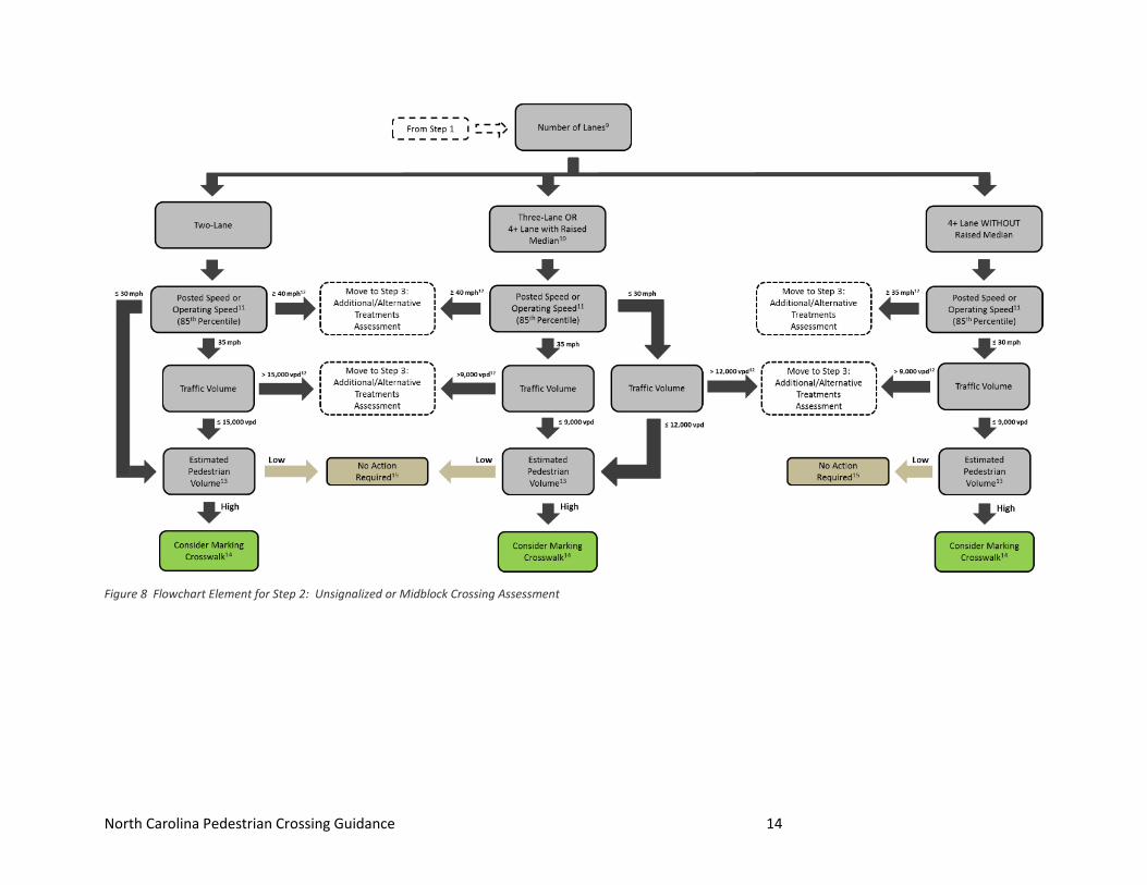
Figure 8 Flowchart Element for Step 2: Unsignalized or Midblock Crossing Assessment
North Carolina Pedestrian Crossing Guidance 15
2.1 CHECK NUMBER OF LANES The number of lanes is a metric that serves as a proxy for crossing distance. Longer crossing distances
are more challenging for pedestrians to cross safely without assistance. When counting the number of
lanes at a potential crossing location, in general, they should be counted from one edge of right-of-way
to the other, to encompass the full crossing. Multiple lanes in one direction may also increase the
potential for a multiple-threat crash, where a near-lane vehicle who yields to a crossing pedestrian may
block the view of an approaching far-lane vehicle.
The evaluator may also consider each stage of a two-stage pedestrian crossing as a discrete crossing
when counting the number of lanes, provided there is sufficient storage and refuge space in the median
to clearly separate the two crossing directions.
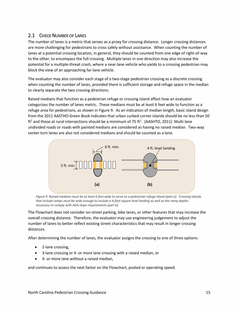
Raised medians that function as a pedestrian refuge or crossing island affect how an evaluator
categorizes the number of lanes metric. These medians must be at least 6 feet wide to function as a
refuge area for pedestrians, as shown in Figure 9. As an indication of median length, basic island design
from the 2011 AASTHO Green Book indicates that urban curbed corner islands should be no less than 50
ft2 and those at rural intersections should be a minimum of 75 ft2. (AASHTO, 2011) Multi-lane
undivided roads or roads with painted medians are considered as having no raised median. Two-way
center turn lanes are also not considered medians and should be counted as a lane.
The Flowchart does not consider on-street parking, bike lanes, or other features that may increase the
overall crossing distance. Therefore, the evaluator may use engineering judgement to adjust the
number of lanes to better reflect existing street characteristics that may result in longer crossing
distances.
After determining the number of lanes, the evaluator assigns the crossing to one of three options:
2-lane crossing,
3-lane crossing or 4- or more lane crossing with a raised median, or
4- or more lane without a raised median,
and continues to assess the next factor on the Flowchart, posted or operating speed.
(a) (b)
Figure 9 Raised medians must be at least 6 feet wide to serve as a pedestrian refuge island (part a). Crossing islands that include ramps must be wide enough to include a 4-foot square level landing as well as the ramp depths necessary to comply with ADA slope requirements (part b).
4 ft. level landing6 ft. min.
5 ft. min.
North Carolina Pedestrian Crossing Guidance 16
2.2 CHECK POSTED SPEED OR OPERATING SPEED For many crossings, the posted speed limit can be used as an approximation of operating conditions.
Where there is a concern that the 85th percentile operating speeds may be near or exceed speed
thresholds indicated on the Flowchart (which are based on posted speeds), a speed study should be
conducted to determine the 85th percentile speed. If both posted and operating speed data are
available, the evaluator should conservatively use whichever speed is higher.
The thresholds below reflect recommendations based on the research findings of a 2005 FHWA study on
Safety Effects of Marked Versus Unmarked Crosswalks at Uncontrolled Locations. (Zegeer, 2005) The
researchers compared five years of crash data from 2,000 crossings across 30 U.S. cities where marked
and unmarked crosswalk sites with otherwise similar characteristics were paired for comparison. The
majority of these sites (93%) had speed limits between 25 to 35 mph, so the lack of variation in speed
limits across sites made it difficult to find a direct relationship between speed and the frequency of
pedestrian crashes. However, the study confirmed the relationship between speed and crash severity,
where speed limits of 35 mph or greater correlated to more fatal or type A (serious or incapacitating)
pedestrian injuries. Given the increase in crash severity, and given that it is not standard practice in the
United States to mark a crosswalk at uncontrolled locations where speed limits are 40 mph or greater,
Zegeer et al. do not recommend marking crosswalks alone under this condition (Zegeer, 2005).
Additionally, pedestrians may have more difficulty judging available gaps as vehicle speeds increase.
Regardless of the number of lanes, for crossings where vehicle speed is greater than or equal to 40 mph,
the evaluator automatically moves to Step 3 to consider additional treatments. Marking the crosswalk
alone under this condition is not suitable, as it may increase the risk of a pedestrian crash. (Zegeer,
2005) Likewise, for locations with four or more lanes without a raised median where the vehicle speed
is greater than or equal to 35 mph, the Flowchart directs the evaluator to automatically move to Step 3.
2.2.1 On Two-Lane Roads
For two-lane roads, the posted speed or 85th percentile operating speed is evaluated against three
thresholds. A two-lane road typically refers to two-way traffic with one lane in each direction. However,
for four-lane divided facilities, each side of the crossing may be evaluated as a two-lane road, if the
crossing is completed in two distinct stages (interrupted by a median refuge).
Where speed is less than or equal to 30 mph, the speed check is satisfied, and the evaluator
moves to check pedestrian volume.
Where speed is 35 mph, the speed check is satisfied, and the evaluator moves to check traffic
volume.
Where speed is greater than or equal to 40 mph, the speed check fails, and the evaluator moves
to Step 3.
North Carolina Pedestrian Crossing Guidance 17
2.2.2 On Three-Lane Roads or Four-or-More-Lane Roads with a Raised Median
For three-lane roads, or roads with four or more lanes with a raised median, the posted speed or 85th
percentile operating speed is evaluated against only two thresholds.
Where speed is less than or equal to 35 mph, the speed check is satisfied and the evaluator
moves to check traffic volume.
Where speed is greater than or equal to 40 mph, the speed check fails, and the evaluator moves
to Step 3.
2.2.3 On Four-or-More-Lane Roads without a Raised Median
For roads with four or more lanes that do not have a raised median, the posted speed or 85th percentile
operating speed is evaluated against two thresholds.
Where speed is less than or equal to 30 mph, the speed check is satisfied, and the evaluator
moves to check traffic volume.
Where speed is greater than or equal to 35 mph, the speed check fails, and the evaluator moves
to Step 3.
2.3 CHECK VEHICLE VOLUME Gap opportunities are a function of vehicle volume. While multilane facilities may be associated with
higher vehicle volumes, they may not be inherently more difficult to cross. The same number of vehicles
per day on a two-lane road compared to a multilane road could allow pedestrians more gap
opportunities on the multilane facility, thereby making it effectively easier to cross. Therefore, only
checking the number of lanes of a crossing is an insufficient proxy for measuring vehicle volumes and
understanding gap opportunities. Zegeer et al. found that traffic volume is one of the primary factors
associated with pedestrian crashes. (2005) It is noted though that multilane facilities may pose a risk of
multiple threat situations as discussed above, which should be included as an additional safety
consideration in the overall assessment.
The traffic volume thresholds below are supported by the 2005 study by Zegeer. At potential crossing
locations where the traffic volume is close to a given threshold, engineering judgement should be used
with consideration of additional factors, such as crash history, presence of special pedestrian
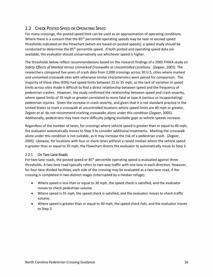
Figure 10 At an unsignalized intersection, if the posted or operating speed of a two-lane road is greater than or equal to 40 mph, marking a crosswalk alone is not recommended as it may increase the risk of a pedestrian crash.
North Carolina Pedestrian Crossing Guidance 18
populations like the elderly, heavy truck volumes, etc. to decide which branch of the Flowchart to
follow.
Regardless of the number of lanes or speed, for crossings where traffic volume is greater than or equal
to 15,000 vpd, the evaluator automatically moves to Step 3 to consider additional treatments. Marking
the crosswalk alone under this condition is not suitable, as it may increase the risk of a pedestrian crash.
(Zegeer, 2005)
2.3.1 On Two-Lane Roads, 35 mph
For two-lane roads with a speed of 35 mph, the traffic volumes are evaluated based on a threshold
volume of 15,000 vehicles per day (vpd).
Where traffic volume is less than or equal to 15,000 vpd, the traffic volume is satisfied, and the
evaluator moves to check pedestrian volume.
Where traffic volume is greater than 15,000 vpd, the traffic volume check fails, and the
evaluator moves to Step 3.
2.3.2 On Three-Lane Roads or Four-or-More-Lane Roads with a Raised Median, 30 mph or Less
For three-lane roads, or roads with four or more lanes with a raised median and a speed for 30 mph or
less, the traffic volumes are evaluated based on a threshold volume of 12,000 vpd.
Where traffic volume is less than 12,000 vpd, the traffic volume check is satisfied and the
evaluator moves to check pedestrian volume.
Where traffic volume is greater than or equal to 12,000 vpd, the traffic volume check fails, and
the evaluator moves to Step 3.
2.3.3 On Three-Lane Roads or Four-or-More-Lane Roads with a Raised Median, 35 mph
For three-lane roads, or roads with four or more lanes with a raised median and a speed for 35 mph, the
traffic volumes are evaluated based on a threshold volume of 9,000 vpd.
Where traffic volume is less than or equal to 9,000 vpd, the traffic volume check is satisfied and
the evaluator moves to check pedestrian volume.
Where traffic volume is greater than 9,000 vpd, the traffic volume check fails, and the evaluator
moves to Step 3.
2.3.4 On Four-or-More-Lane Roads without a Raised Median, 30 mph or Less
For roads with four or more lanes without a raised median and a speed for 30 mph or less, the traffic
volumes are evaluated based on a threshold volume of 9,000 vpd.
Where traffic volume is less than or equal to 9,000 vpd, the traffic volume check is satisfied, and
the evaluator moves to check pedestrian volume.
Where traffic volume is greater than 9,000 vpd, the traffic volume check fails, and the evaluator
moves to Step 3.
North Carolina Pedestrian Crossing Guidance 19
2.4 CHECK PEDESTRIAN VOLUME See Section 1.3.2.2 above for more on how to conduct this check to determine whether the estimated
pedestrian volume at a potential crossing is low.
Where pedestrian volume is Low, no action is required. The gap availability, based on number
of lanes, speed, and traffic volume, should allow for sufficient crossing opportunities.
Where pedestrian volume is not Low, the evaluator may consider marking a crosswalk.8
8 Use engineering judgment based on location context to determine if the crosswalk should be marked and what type of pattern is most appropriate. Mid-block crosswalks should be marked using a high-visibility pattern. (NCDOT, 2008) High-visibility markings may also be appropriate for school crosswalks or where pedestrians or marked crosswalks may not be expected by drivers. (National Committee on Uniform Traffic Control Devices, 2011)
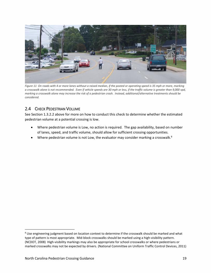
Figure 11 On roads with 4 or more lanes without a raised median, if the posted or operating speed is 35 mph or more, marking a crosswalk alone is not recommended. Even if vehicle speeds are 30 mph or less, if the traffic volume is greater than 9,000 vpd, marking a crosswalk alone may increase the risk of a pedestrian crash. Instead, additional/alternative treatments should be considered.
North Carolina Pedestrian Crossing Guidance 20
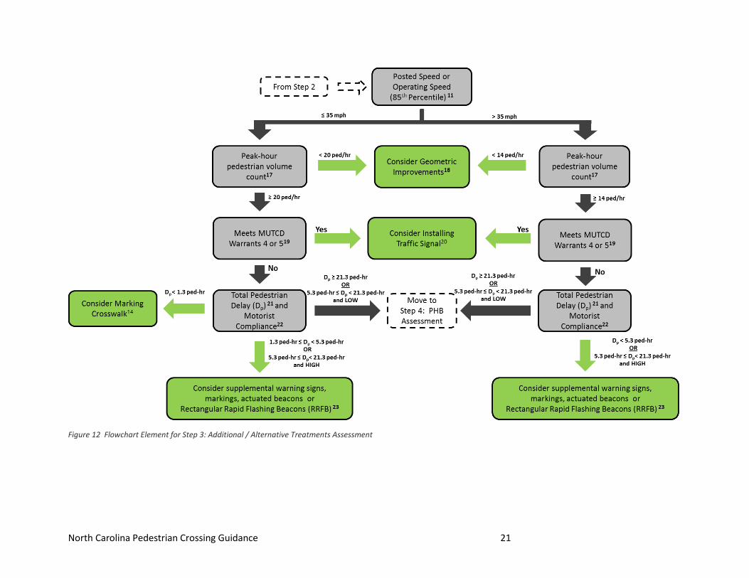
3 STEP 3: ADDITIONAL / ALTERNATIVE TREATMENTS ASSESSMENT
There are four (4) potential checks to complete as part of Step 3:
1) Check posted or operating speed
2) Check pedestrian volume
3) Check MUTCD signal warrants
4) Check pedestrian delay
After moving through the Step 3 Flowchart element, an evaluator will end at one of five (5) potential
outcomes:
Consider Geometric Improvements
Consider Installing a Traffic Signal
Consider Marking Crosswalk
Consider Supplemental Treatments
Move to Step 4
Factors and thresholds within Step 3 are predicated on research findings and guidance conveyed in
NCHRP Report 562: Improving Pedestrian Safety at Unsignalized Crossings. (Fitzpatrick, et al., NCHRP
Report 562: Improving Pedestrian Safety at Unsignalized Crossings, 2006) This report includes
“Appendix A. Guidelines for Pedestrian Crossing Treatments” which comprises a process and worksheet
tools to determine general recommendations for crossing treatment types to consider at an
unsignalized location. The inputs used in Fitzpatrick’s guidance are reflected in the checks within Step 3
of NCDOT’s Flowchart.
North Carolina Pedestrian Crossing Guidance 21
Figure 12 Flowchart Element for Step 3: Additional / Alternative Treatments Assessment
North Carolina Pedestrian Crossing Guidance 22
3.1 CHECK SPEED For many crossings, the posted speed limit can be used as an approximation of operating conditions.
Where there is a concern or evidence that the 85th percentile operating speeds may be near or exceed
35 mph, a speed study can be conducted to determine the 85th percentile speed. If both posted and
operating speed data are available, the evaluator should conservatively use whichever speed is higher.
When comparing motorist yielding compliance at a variety of crossing treatments on roads with posted
speed limits ranging from 25 to 40 mph, Fitzpatrick et al. found a critical speed of 35 mph – the best
compliance of non-red indicating devices was observed at treatments on roads with posted speeds less
than 35 mph. (2006) Therefore, the path to proceed through Step 3 depends on whether the crossing
location is on a roadway with a posted speed limit above 35 mph or at 35 mph or below.
3.2 CHECK PEAK-HOUR PEDESTRIAN VOLUME Step 3 requires observed pedestrian volume data, rather than estimated volume based on proxy
information. Count thresholds include pedestrians crossing the roadway within 150 ft. of the crossing
location being assessed. At an intersection, pedestrians are counted crossing in both directions and
across both legs of the roadway assessed, as shown in Figure 13. Note that this check is for the
pedestrian peak-hour volume, which may not necessarily be the same peak-hour as the vehicles. For
example, near a school, the pedestrian peak-hour may align with school dismissal, whereas the vehicle
peak-hour may be up to three hours later. If the pedestrian peak hour time is not known, an initial
pedestrian count study should be conducted using the general guidelines recommended in section
1.3.2.2 above.
Figure 13 In this example, the crossing being evaluated is the west leg. Pedestrians are counted crossing northbound and southbound on the east and west legs (shown by black arrows) and up to 150 feet away from the intersection (shown by yellow highlighted area).
North Carolina Pedestrian Crossing Guidance 23
3.2.1 On Road with Speed 35 mph or Less
On roads with a posted speed or 85th percentile operating speed of 35 mph or less, a pedestrian volume
threshold of 20 pedestrians per pedestrian peak hour applies.
Where the peak-hour pedestrian volume is less than 20 pedestrians per hour, consider
geometric improvements.
Where the peak-hour pedestrian volume is greater than or equal to 20 pedestrians per hour,
check MUTCD signal warrants.
3.2.2 On Road with Speed Greater than 35 mph
On roads with a posted speed or 85th percentile operating speed greater than 35 mph, a pedestrian
volume threshold of 14 pedestrians per pedestrian peak hour applies.
Where the peak-hour pedestrian volume is less than 14 pedestrians per hour, consider
geometric improvements.
Where the peak-hour pedestrian volume is greater than or equal to 14 pedestrians per hour,
check MUTCD signal warrants.
When considering geometric improvements, further engineering study is needed to determine what, if
any modifications should be implemented. These improvements may include the installation of median
refuge islands, curb extensions, or traffic calming devices. Improvements may also include other
modifications that minimize the crossing distance, straighten crossings to be as perpendicular as feasible
to the traffic being crossed, and enhance visibility of and by the pedestrian by removing obstacles to
lines of sight. See the common resources list in Appendix A for more on the countermeasures studied
for NCHRP Report 562 and a link to PEDSAFE for other countermeasure options.
3.3 CHECK MUTCD WARRANTS 4 OR 5 A traffic signal may be warranted based on pedestrian volume. The evaluator must conduct an
engineering study per the MUTCD to determine if a traffic signal may be justified based on minimum
conditions.9 While other relevant traffic signal warrants may simultaneously be analyzed through the
study, of particular relevance to the pedestrian crossing evaluation process is whether Warrant 4 -
Pedestrian Volume or Warrant 5 - School Crossing, is satisfied. The following is paraphrased from the
2009 MUTCD. The full language of the MUTCD for Warrants 4 and 5, including the referenced charts,
are provided in Appendix B.
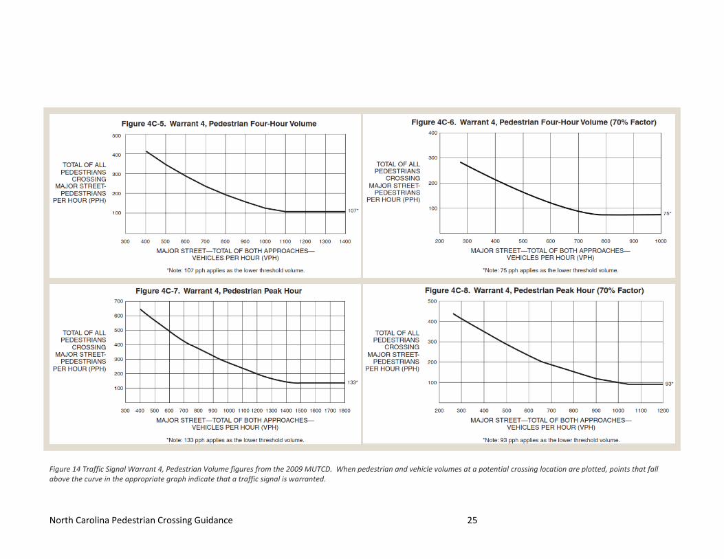
Per Section 4C.05, the Pedestrian Volume signal warrant is met and a traffic signal must be considered if:
For each of any 4 hours of an average day, there are at least 107 pedestrians per hour crossing a
street with at least 1,100 vehicles per hour; or
For any 1 hour of an average day, there are at least 133 pedestrians per hour crossing a street
with at least 1,450 vehicles per hour.
9 2009 MUTCD 4C.01 indicates the “satisfaction of a traffic signal warrant shall not in itself require the installation of a traffic control signal.” (Federal Highway Administration, 2009)
North Carolina Pedestrian Crossing Guidance 24
If the posted or 85th percentile operating speeds are greater than 35 mph or if the crossing location is in
a “built-up area of an isolated community having a population of less than 10,000” then the pedestrian
volume thresholds are lowered to:
At least 75 pedestrians per hour where for any 4 hours crossing at least 750 vehicles per hour;
or
At least 93 pedestrians per hour for any 1 hour crossing at least 1,050 vehicles per hour.
North Carolina Pedestrian Crossing Guidance 25
Figure 14 Traffic Signal Warrant 4, Pedestrian Volume figures from the 2009 MUTCD. When pedestrian and vehicle volumes at a potential crossing location are plotted, points that fall above the curve in the appropriate graph indicate that a traffic signal is warranted.
North Carolina Pedestrian Crossing Guidance 26
Meeting Warrant 4 is a function of both
pedestrian and vehicle volumes at the
crossing. Therefore, as vehicle volumes
decrease, the threshold for the pedestrian
volume needed to meet the warrant rises.
See the figures in Figure 14 above for more
details – plotted points that fall above the
curve in the appropriate figure from the
2009 MUTCD (4C-5, -6, -7, or -8) indicate
the Warrant is met.
Warrant 5 applies when a particular subset
of pedestrians at a crossing is
schoolchildren, and the crossing is
established as a school crossing. The
warrant is a function of gap frequency and
schoolchildren volume. It is met if at least
20 schoolchildren are crossing at the peak
crossing hour and the number of gaps is less
than the number of minutes during the
period when they are crossing.
Neither Warrant applies if the crossing location is less than 300 feet of another signalized or STOP
controlled intersection unless the proposed signal will not restrict progressive movement of traffic.
(4C.05.04 and 4C.06.04)
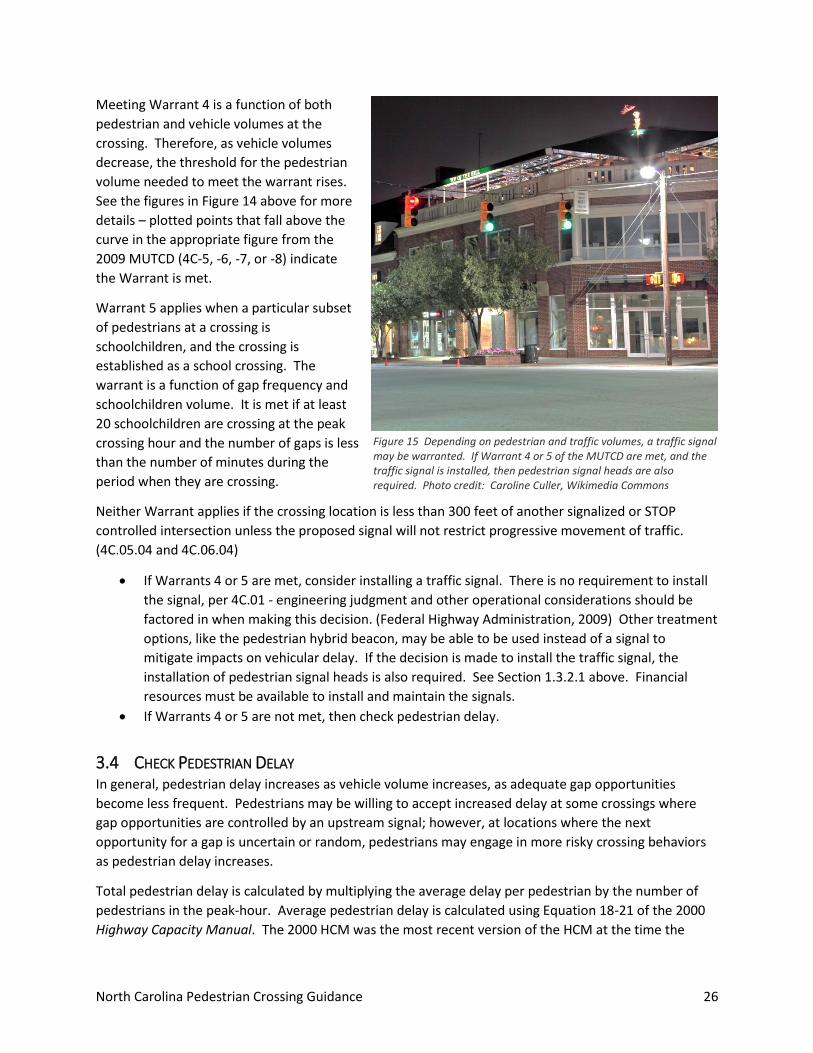
If Warrants 4 or 5 are met, consider installing a traffic signal. There is no requirement to install
the signal, per 4C.01 - engineering judgment and other operational considerations should be
factored in when making this decision. (Federal Highway Administration, 2009) Other treatment
options, like the pedestrian hybrid beacon, may be able to be used instead of a signal to
mitigate impacts on vehicular delay. If the decision is made to install the traffic signal, the
installation of pedestrian signal heads is also required. See Section 1.3.2.1 above. Financial
resources must be available to install and maintain the signals.
If Warrants 4 or 5 are not met, then check pedestrian delay.
3.4 CHECK PEDESTRIAN DELAY In general, pedestrian delay increases as vehicle volume increases, as adequate gap opportunities
become less frequent. Pedestrians may be willing to accept increased delay at some crossings where
gap opportunities are controlled by an upstream signal; however, at locations where the next
opportunity for a gap is uncertain or random, pedestrians may engage in more risky crossing behaviors
as pedestrian delay increases.
Total pedestrian delay is calculated by multiplying the average delay per pedestrian by the number of
pedestrians in the peak-hour. Average pedestrian delay is calculated using Equation 18-21 of the 2000
Highway Capacity Manual. The 2000 HCM was the most recent version of the HCM at the time the
Figure 15 Depending on pedestrian and traffic volumes, a traffic signal may be warranted. If Warrant 4 or 5 of the MUTCD are met, and the traffic signal is installed, then pedestrian signal heads are also required. Photo credit: Caroline Culler, Wikimedia Commons
North Carolina Pedestrian Crossing Guidance 27
Fitzpatrick et al (2006) study was conducted. Newer versions of the HCM feature slightly revised
pedestrian analysis methods, but the crosswalk research was calibrated based on the 2000 HCM.
Average pedestrian delay is a function of crossing distance, walking speed, pedestrian start-up and end
clearance time, and traffic volume and flow rate. The peak-hour pedestrian volume gathered in Section
3.2 above is used for the number of pedestrians. For example, if the HCM delay is estimated as 40
seconds per pedestrian, and the peak-hour volume observed is 90 pedestrians, then:
𝑇𝑜𝑡𝑎𝑙 𝐷𝑒𝑙𝑎𝑦 = 40 𝑠𝑒𝑐
𝑝𝑒𝑑 × 90
𝑝𝑒𝑑
ℎ𝑟 ×
1 ℎ𝑟
3600 𝑠𝑒𝑐= 1 𝑝𝑒𝑑-ℎ𝑟
The Total Pedestrian Delay thresholds and treatment considerations below are based on the research
conducted to inform the “Guidelines for Pedestrian Crossing Treatments” described in Appendix A of
NCHRP Report 562. (Fitzpatrick, et al., NCHRP Report 562: Improving Pedestrian Safety at Unsignalized
Crossings, 2006) The worksheets, inputs, and variables from Report 562 used to calculate total
pedestrian delay are also included in Appendix C of this guidebook.
3.4.1 On Road with Speed 35 mph or Less
On roads with a posted speed or 85th percentile operating speed of 35 mph or less, three potential
conditions are distinguished, based on pedestrian delay and motorist compliance.
Where the total pedestrian delay is less than 1.3 pedestrian-hours, consider marking a
crosswalk.10
Where motorist compliance is LOW11:
o And the total pedestrian delay is greater than or equal to 1.3 pedestrian-hours but less
than 5.3 pedestrian-hours, consider supplemental warning signs, markings, actuated
beacons or Rectangular Rapid Flashing Beacons (RRFB).
o And the total pedestrian delay is greater than or equal to 5.3 pedestrian-hours but less
than 21.3 pedestrian-hours, move to Step 4.
Where motorist compliance is HIGH:
o And the total pedestrian delay is greater than or equal to 5.3 pedestrian-hours but less
than 21.3 pedestrian-hours, consider supplemental warning signs, markings, actuated
beacons or Rectangular Rapid Flashing Beacons (RRFB).
o And the total pedestrian delay is greater than 21.3 pedestrian-hours, move to Step 4.
10 Use engineering judgment based on location context to determine if the crosswalk should be marked and what type of pattern is most appropriate. Mid-block crosswalks should be marked using a high-visibility pattern. (NCDOT, 2008) High-visibility markings may also be appropriate for school crosswalks or where pedestrians or marked crosswalks may not be expected by drivers. (National Committee on Uniform Traffic Control Devices, 2011) 11 Motorist compliance is considered “HIGH” if, within the general vicinity of the crossing location, driver culture is such that motorists tend to yield to a pedestrian attempting to cross at an uncontrolled location. If motorists rarely stop for a crossing pedestrian, then compliance is considered “LOW”. (Fitzpatrick, et al., NCHRP Report 562: Improving Pedestrian Safety at Unsignalized Crossings, 2006)
North Carolina Pedestrian Crossing Guidance 28
3.4.2 On Road with Speed Greater than 35 mph
On roads with a posted speed or 85th percentile operating speed greater than 35 mph, two potential
conditions are distinguished, based on pedestrian delay and motorist compliance.
Where motorist compliance is LOW:
o And the total pedestrian delay is less than 5.3 pedestrian-hours, consider supplemental
warning signs, markings, actuated beacons or Rectangular Rapid Flashing Beacons
(RRFB).
o And the total pedestrian delay is greater than or equal to 5.3 pedestrian-hours but less
than 21.3 pedestrian-hours, move to Step 4.
Where motorist compliance is HIGH:
o And the total pedestrian delay is greater than or equal to 5.3 pedestrian-hours but less
than 21.3 pedestrian-hours, consider supplemental warning signs, markings, actuated
beacons or Rectangular Rapid Flashing Beacons (RRFB).
o And the total pedestrian delay is greater than 21.3 pedestrian-hours, move to Step 4.
Supplemental signs, markings, and beacons include devices that enhance the visibility of the crossing
beyond the standard marked crosswalk and pedestrian crossing signs. These devices may include
advanced yield lines and signage, in-street Yield-to-Pedestrian signs, overhead signage, or pedestrian-
actuated beacons such as the RRFB, among others. Additional study is needed to determine what, if any
enhanced or active traffic control devices should be implemented. See the Common Resources List in
Appendix A for more on these or other options.
3.4.3 Quick Reference Charts to Estimate Total Pedestrian Delay
While the evaluator may choose to employ the worksheets provided in NCHRP Report 562 to calculate
Total Pedestrian Delay, a series of charts are provided in Appendix C to quickly estimate this factor.
These charts are organized by posted speed limit, crossing distance, and community population
thresholds, and are a function of peak-hour pedestrian volumes and peak-hour traffic volumes. The
evaluator selects the appropriate chart and then plots the peak-hour pedestrian and traffic volumes at
the potential crossing location. Three curves are given on each chart, which reflect the 1.3, 5.3, and 21.3
pedestrian-hour thresholds of Total Pedestrian Delay. Depending on where a point is plotted, Total
Pedestrian Delay may be Low, Medium-Low, Medium-High, or High:
Plotted points that fall below the 1.3 ped-hr line are considered Low;
Plotted points that fall between the 1.3 ped-hr and 5.3 ped-hr lines are considered Medium-
Low;
Plotted points that fall between the 5.3 ped-hr and 21.3 ped-hr lines are considered Medium-
High;
Plotted points that fall above the 21.3 ped-hour line are considered High.
Table 1 is used to then identify the appropriate treatment category based on the speed limit, motorist
compliance and type of Total Pedestrian Delay.

North Carolina Pedestrian Crossing Guidance 29
Table 1 Total Pedestrian Delay – Treatment Selection Guidance
Speed Motorist
Compliance
Total Pedestrian Delay Type
Low (< 1.3 ped-hrs)
Medium-Low (≥ 1.3 to < 5.3
ped-hrs)
Medium-High (≥ 5.3 to < 21.3
ped-hrs)
High (≥ 21.3 ped-hrs)
≤ 35 mph
Low Consider Marking
Crosswalk
Consider Supplemental
Treatments Move to Step 4 Move to Step 4
High Consider Marking
Crosswalk
Consider Supplemental
Treatments
Consider Supplemental
Treatments Move to Step 4
> 35 mph
Low Consider
Supplemental Treatments
Consider Supplemental
Treatments Move to Step 4 Move to Step 4
High Consider
Supplemental Treatments
Consider Supplemental
Treatments
Consider Supplemental
Treatments Move to Step 4
Figure 16 illustrates a plotted point in the Medium-High category. In this example, because the Total
Pedestrian Delay is Medium High, the speed is less than 35 mph, and motorist compliance is low, Table 1
indicates that the evaluator move to Step 4 to continue to assess the crossing location for a Pedestrian
Hybrid Beacon.
Example Scenario
Crossing location: road in an urban area.
Speed limit or 85th percentile operating speed: 35 mph or less.
Crossing distance: 36 ft.
Peak-hour vehicle volume: 2,000.
Peak-hour pedestrian volume: 20.
Motorist Compliance: Low 0
10
20
30
40
50
60
70
80
90
100
0 1000 2000 3000 4000 5000 6000 7000
Ho
url
y P
ed
est
rian
Vo
lum
e (
pe
d/h
)
Hourly Vehicle Volume Both Directions (veh/h)
Speed Limit 20-35 mph - Crossing Distance 36' - Population ≥ 10,000
Total Pedestrian Delay = 1.3 hours
Total Pedestrian Delay = 5.3 hours
Total Pedestrian Delay = 21.3 hours
Figure 16 Example scenario using the “Speed Limit 20-35 mph – Crossing Distance 36’ – Population ≥ 10,000” chart from Appendix C.to determine Total Pedestrian Delay type. Example shows a Medium-High delay between 5.3 and 21.3 ped-hrs.
North Carolina Pedestrian Crossing Guidance 30
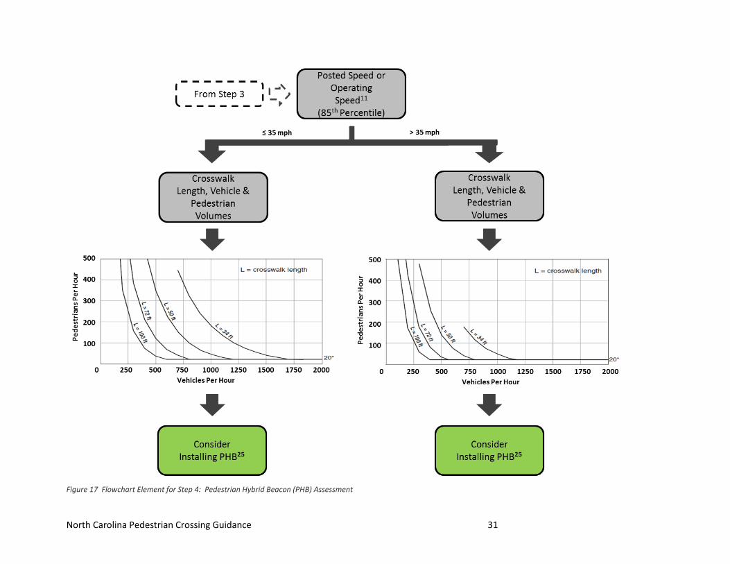
4 STEP 4: PEDESTRIAN HYBRID BEACON ASSESSMENT
There are four (4) checks to complete as part of Step 4:
1) Check posted or operating speed
2) Check crosswalk length
3) Check pedestrian volume
4) Check vehicle volume
After moving through the Step 4 Flowchart element, the evaluator will determine whether to consider
installing a Pedestrian Hybrid Beacon (PHB).
Factors and thresholds within Step 4 are from the 2009 MUTCD in Section 4F.01.06 and 4F.01.07, which
is predicated on research findings and guidance conveyed in NCHRP Report 562: Improving Pedestrian
Safety at Unsignalized Crossings. (Fitzpatrick, et al., NCHRP Report 562: Improving Pedestrian Safety at
Unsignalized Crossings, 2006) Step 4 of the Flowchart is essentially a continuation of Step 3. While Step
3 follows the guidelines in Report 562 to reach treatment category endpoints of “Crosswalk” or “Active
or Enhanced”, the “Red” treatment category of Report 562 is assessed through Step 4.
North Carolina Pedestrian Crossing Guidance 31
Figure 17 Flowchart Element for Step 4: Pedestrian Hybrid Beacon (PHB) Assessment
North Carolina Pedestrian Crossing Guidance 32
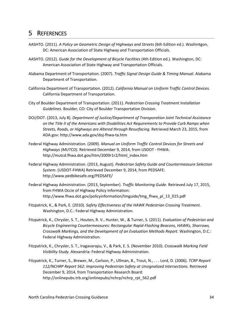
4.1 CHECK SPEED See Section 3.1 above – the posted or operating speed used in Step 3 is carried through to Step 4.
4.2 CHECK CROSSWALK LENGTH, VEHICLE & PEDESTRIAN VOLUMES Crosswalk length represents the distance a pedestrian would need to cross before reaching either a
raised median refuge island or the far curb or edge of pavement. On-street parking, bike lanes, or other
features that may increase the overall crossing distance should be included in the crosswalk length
measurement.
When determining the number of vehicles per peak-hour, the evaluator must first consider whether
vehicle volume should represent one or both approaches. Per Section 4F.07 of the 2009 MUTCD, the
total of both approaches should be used. This assumes that a pedestrian should be able to cross from
one curb to the far curb. Where a raised median is sufficiently designed to serve as a pedestrian refuge
island (see Section 2.1 for minimum island design dimensions), the crossing task may effectively function
as a two-stage crossing. In this case, each approach can be separately assessed, using the peak-hour
vehicle volume for an approach and the corresponding crosswalk length to the island.
See Section 3.2 above for determining pedestrian volume.
Once vehicle and pedestrian volumes are known, the evaluator plots the point on the appropriate graph
based on the posted or operating speed. Figure 4F-1 from the 2009 MUTCD (shown in Figure 18) is used
where the roadway is 35 mph or less while Figure 4F-2 (shown in Figure 19) is used if the speed is
greater than 35mph.
4.2.1 On Road with Speed Less Than or Equal to 35 mph
On roads with a posted speed or 85th percentile operating speed of 35 mph or less, two potential
conditions are distinguished, based on the crosswalk length curve.
A PHB is recommended for consideration where the plotted point falls above the curve for the
appropriate crosswalk length line on the graph in Figure 18.
If the plotted point falls below the applicable curve, consider supplemental warning signs,
markings, actuated beacons or RRFBs.
4.2.2 On Road with Speed Greater than 35 mph
On roads with a posted speed or 85th percentile operating speed of greater than 35, two potential
conditions are distinguished, based on the crosswalk length curve.
A PHB is recommended for consideration where the plotted point falls above the curve for the
appropriate crosswalk length line on the graph Figure 19.
If the plotted point falls below the applicable curve, consider supplemental warning signs,
markings, actuated beacons or RRFBs.
The evaluator interpolates values between curves if the measured crosswalk length is not represented
by one of the four graphed. Consideration for installation of a PHB assumes that a traffic signal was not
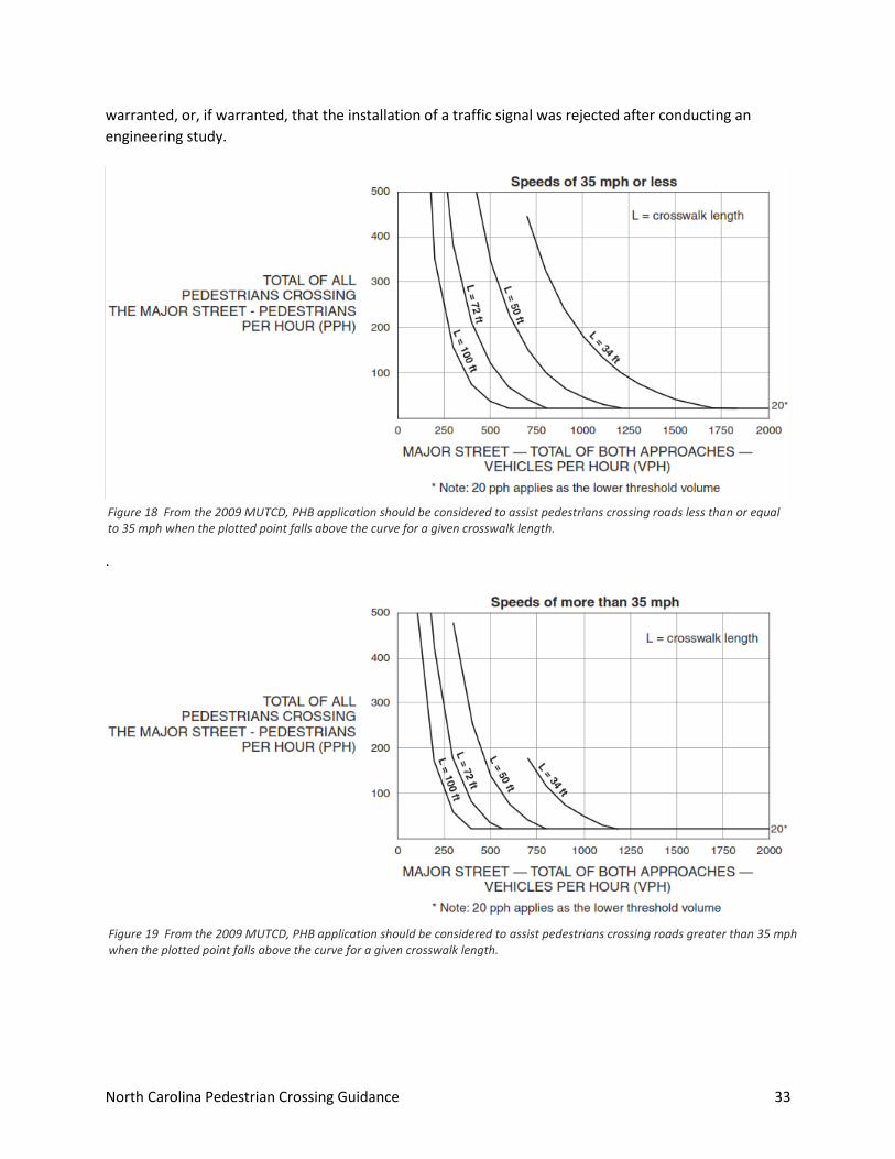
North Carolina Pedestrian Crossing Guidance 33
warranted, or, if warranted, that the installation of a traffic signal was rejected after conducting an
engineering study.
.
Figure 18 From the 2009 MUTCD, PHB application should be considered to assist pedestrians crossing roads less than or equal to 35 mph when the plotted point falls above the curve for a given crosswalk length.
Figure 19 From the 2009 MUTCD, PHB application should be considered to assist pedestrians crossing roads greater than 35 mph when the plotted point falls above the curve for a given crosswalk length.
North Carolina Pedestrian Crossing Guidance 34
5 REFERENCES
AASHTO. (2011). A Policy on Geometric Design of Highways and Streets (6th Edition ed.). Washintgon,
DC: American Association of State Highway and Transportation Officials.
AASHTO. (2012). Guide for the Development of Bicycle Facilities (4th Edition ed.). Washington, DC:
American Association of State Highway and Transportation Officials.
Alabama Department of Transportation. (2007). Traffic Signal Design Guide & Timing Manual. Alabama
Department of Transportation.
California Department of Transportation. (2012). California Manual on Uniform Traffic Control Devices.
California Department of Transportation.
City of Boulder Department of Transportation. (2011). Pedestrian Crossing Treatment Installation
Guidelines. Boulder, CO: City of Boulder Transportation Division.
DOJ/DOT. (2013, July 8). Department of Justice/Department of Transporation Joint Technical Assistance
on the Title II of the Americans with Disabilities Act Requirements to Provide Curb Ramps when
Streets, Roads, or Highways are Altered through Resurfacing. Retrieved March 23, 2015, from
ADA.gov: http://www.ada.gov/doj-fhwa-ta.htm
Federal Highway Administration. (2009). Manual on Uniform Traffic Control Devices for Streets and
Highways (MUTCD). Retrieved December 9, 2014, from USDOT - FHWA:
http://mutcd.fhwa.dot.gov/htm/2009r1r2/html_index.htm
Federal Highway Administration. (2013, August). Pedestrian Safety Guide and Countermeasure Selection
System. (USDOT-FHWA) Retrieved December 9, 2014, from PEDSAFE:
http://www.pedbikesafe.org/PEDSAFE/
Federal Highway Administration. (2013, September). Traffic Monitoring Guide. Retrieved July 17, 2015,
from FHWA Occie of Highway Policy Information:
http://www.fhwa.dot.gov/policyinformation/tmguide/tmg_fhwa_pl_13_015.pdf
Fitzpatrick, K., & Park, E. (2010). Safety Effectiveness of the HAWK Pedestrian Crossing Treatment.
Washington, D.C.: Federal Highway Administration.
Fitzpatrick, K., Chrysler, S. T., Houten, R. V., Hunter, W., & Turner, S. (2011). Evaluation of Pedestrian and
Bicycle Engineering Countermeasures: Rectangular Rapid-Flashing Beacons, HAWKs, Sharrows,
Crosswalk Markings, and the Development of an Evaluation Methods Report. Washington, D.C.:
Federal Highway Administration.
Fitzpatrick, K., Chrysler, S. T., Iragavarapu, V., & Park, E. S. (November 2010). Crosswalk Marking Field
Visibility Study. Alexandria: Federal Highway Administration.
Fitzpatrick, K., Turner, S., Brewer, M., Carlson, P., Ullman, B., Trout, N., . . . Lord, D. (2006). TCRP Report
112/NCHRP Report 562: Improving Pedestrian Safety at Unsignalized Intersections. Retrieved
December 9, 2014, from Transportation Research Board:
http://onlinepubs.trb.org/onlinepubs/nchrp/nchrp_rpt_562.pdf
North Carolina Pedestrian Crossing Guidance 35
Georgia Department of Transportation. (2011). Signal Design Guidelines. Georgia Department of
Transportation.
Lacy, K. (2011, October 20). Alternate Curb Ramp Designs Memorandum. Retrieved March 23, 2015,
from NCDOT.gov:
https://connect.ncdot.gov/resources/safety/Teppl/TEPPL%20All%20Documents%20Library/C53
%20%E2%80%93%20Memo%20111020.pdf
Lagerwey, P. A., Hintze, M. J., Elliott, J. B., Toole, J. L., & Schneider, R. J. (2015). Pedestrian and Bicycle
Transportation Along Existing Roads - ActiveTrans Priority Tool Guidebook. Washington, DC:
Transportation Research Board of the National Academies. Retrieved April 27, 2015, from
http://onlinepubs.trb.org/onlinepubs/nchrp/nchrp_rpt_803.pdf
Minnesota Department of Transportation. (2005). Guidance for Installation of Pedestrian Crosswalks on
Minnesota State Highways. Minnesota Department of Transportation.
National Committee on Uniform Traffic Control Devices. (2011, June). June 2011 Meeting- Council
Minutes Attachment No. 3 Markings-Sec.3B.18. Retrieved April 16, 2015, from NCUTCD:
http://www.ncutcd.org/doc/201106/Attach%20No.%203%20Markings-
Sec.%203B.18%20Apprvd%206-23-11.docx
NCDOT. (2008, February 2). Standard Practice for Crosswalks - Mid-Block (Unsignalized) Signing.
Retrieved April 10, 2015, from NCDOT.gov:
https://connect.ncdot.gov/resources/safety/Teppl/TEPPL%20All%20Documents%20Library/C-
36_pr.pdf
NCDOT. (2009, September 18). Standard Practice for Pedestrian Reasonable Access Requests from
Pedestrians with Qualifying Disabilities under the Americans with Disabilities Act. Retrieved
March 24, 2015, from NCDOT.gov:
https://connect.ncdot.gov/resources/safety/Teppl/TEPPL%20All%20Documents%20Library/Disa
bled_Ped_Practice.pdf
NCDOT Division 3. (December 21, 2010). Pedestrian Crosswalks in Beach Communities Guidelines. North
Carolina Department of Transportation.
Nordback, K., Marshall, W. E., Janson, B. N., & Stolz, E. (2013). Estimating Annual Average Daily
Bicyclists: Error and Accuracy. (T. R. Academies, Ed.) Transportation Research Record: Journal of
the Transportation Research Board, No. 2339, 90-97.
Pedestrian and Bicycle Information Center (PBIC). (n.d.). Traffic Signals. Retrieved from SRTS guide:
http://guide.saferoutesinfo.org/engineering/traffic_signals.cfm
Rodegerdts, L., & et al. (2007). Roundabouts in the United States. Washington, D.C.: Transportation
Research Board.
Sacramento Transportation & Air Quality Collaborative. (2005). Best Practices for Pedestrian Master
Planning and Design. Sacramento, CA: Sacramento Transportation & Air Quality Collaborative.
North Carolina Pedestrian Crossing Guidance 36
Thomas, L., Levitt, D., & Farley, E. (2014, March). North Carolina Pedestrian Crash Types 2008-2012.
Retrieved December 8, 2014, from North Carolina Pedestrian and Bicycle Crash Data Tool:
http://www.pedbikeinfo.org/pbcat_nc/pdf/summary_ped_types08-12.pdf
Transportation Research Board. (2010). Highway Capacity Manual (HCM). Washington, D.C.:
Transportation Research Board (TRB).
Troutbeck, R. J., & Brilon, W. (2002). Chapter 8: Unsignalized Intersection Theory. In Revised Monograph
on Traffic Flow Theory. Turner-Fairbank Highway Research Center.
Uncontrolled Crossings Task Force. (2014, March). Current Practices Survey. Retrieved December 4,
2014, from America Walks: http://americawalks.org/wp-content/upload/America-Walks-
Crosswalk-Practices-Survey.March2014.pdf
US Access Board. (2002, September). ADA Accessibility Guidelines (ADAAG). Retrieved March 23, 2015,
from Access-Board.gov: http://www.access-board.gov/guidelines-and-standards/buildings-and-
sites/about-the-ada-standards/background/adaag
US Access Board. (2006). Revised Draft Guidelines for Accessible Public Rights-of-Way. Retrieved from US
Access Board: http://www.access-board.gov/prowac/draft.htm
Zegeer. (2005, September). Safety Effects of Marked Versus Unmarked Crosswalks at Uncontrolled
Locations: Final Report and Recommended Guidelines. Retrieved April 13, 2015, from Federal
Highway Administration:
http://www.fhwa.dot.gov/publications/research/safety/04100/04100.pdf
Zegeer, C. V., Stewart, J. R., Huang, H. H., & Lagerwey, P. A. (2002, February). Safety Effects of Marked
Vs. Unmarked Crosswalks at Uncontrolled Locations: Executive Summary and Recommended
Guidelines. Retrieved December 9, 2014, from Pedestrian and Bicycle Information Center:
http://www.pedbikeinfo.org/collateral/PSAP%20Training/gettraining_references_Effects_Un_M
arkedCrosswalks_Summary.pdf
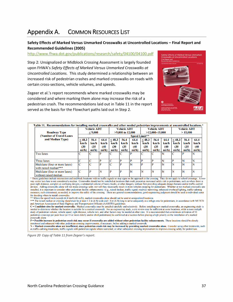
North Carolina Pedestrian Crossing Guidance 37
Appendix A. COMMON RESOURCES LIST
Safety Effects of Marked Versus Unmarked Crosswalks at Uncontrolled Locations – Final Report and
Recommended Guidelines (2005)
http://www.fhwa.dot.gov/publications/research/safety/04100/04100.pdf
Step 2: Unsignalized or Midblock Crossing Assessment is largely founded
upon FHWA’s Safety Effects of Marked Versus Unmarked Crosswalks at
Uncontrolled Locations. This study determined a relationship between an
increased risk of pedestrian crashes and marked crosswalks on roads with
certain cross-sections, vehicle volumes, and speeds.
Zegeer et al.’s report recommends where marked crosswalks may be
considered and where marking them alone may increase the risk of a
pedestrian crash. The recommendations laid out in Table 11 in the report
served as the basis for the Flowchart paths laid out in Step 2.
Figure 20 Copy of Table 11 from Zegeer's report.
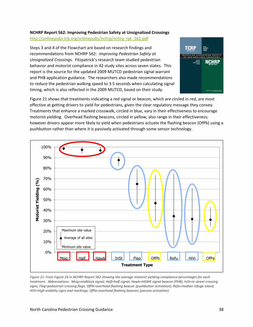
North Carolina Pedestrian Crossing Guidance 38
NCHRP Report 562: Improving Pedestrian Safety at Unsignalized Crossings
http://onlinepubs.trb.org/onlinepubs/nchrp/nchrp_rpt_562.pdf
Steps 3 and 4 of the Flowchart are based on research findings and
recommendations from NCHRP 562: Improving Pedestrian Safety at
Unsignalized Crossings. Fitzpatrick’s research team studied pedestrian
behavior and motorist compliance in 42 study sites across seven states. This
report is the source for the updated 2009 MUTCD pedestrian signal warrant
and PHB application guidance. The researchers also made recommendations
to reduce the pedestrian walking speed to 3.5 seconds when calculating signal
timing, which is also reflected in the 2009 MUTCD, based on their study.
Figure 21 shows that treatments indicating a red signal or beacon, which are circled in red, are most
effective at getting drivers to yield for pedestrians, given the clear regulatory message they convey.
Treatments that enhance a marked crosswalk, circled in blue, vary in their effectiveness to encourage
motorist yielding. Overhead flashing beacons, circled in yellow, also range in their effectiveness;
however drivers appear more likely to yield when pedestrians actuate the flashing beacon (OfPb) using a
pushbutton rather than where it is passively activated through some sensor technology.
0%
10%
20%
30%
40%
50%
60%
70%
80%
90%
100%
Msig Half Hawk InSt Flag OfPb Refu HiVi OfPa
Treatment Type
Mo
tori
st
Yie
ldin
g (
%)
Minimum site value
Maximum site value
Average of all sites
Figure 21 From Figure 24 in NCHRP Report 562 showing the average motorist yielding compliance percentages for each treatment. Abbreviations: Msig=midblock signal; Half=half signal; Hawk=HAWK signal beacon (PHB); InSt=in-street crossing signs; Flag=pedestrian crossing flags; OfPb=overhead flashing beacon (pushbutton activation); Refu=median refuge island; HiVi=high-visibility signs and markings; OfPa=overhead flashing beacons (passive activation)
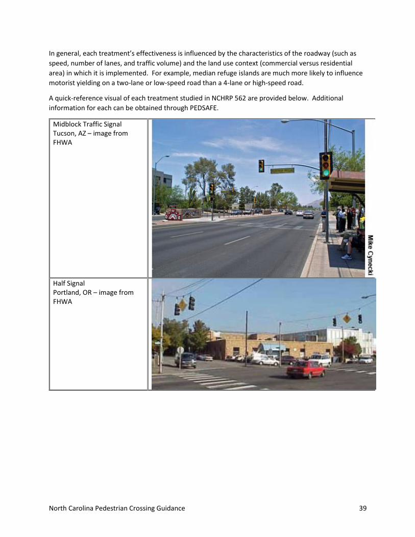
North Carolina Pedestrian Crossing Guidance 39
In general, each treatment’s effectiveness is influenced by the characteristics of the roadway (such as
speed, number of lanes, and traffic volume) and the land use context (commercial versus residential
area) in which it is implemented. For example, median refuge islands are much more likely to influence
motorist yielding on a two-lane or low-speed road than a 4-lane or high-speed road.
A quick-reference visual of each treatment studied in NCHRP 562 are provided below. Additional
information for each can be obtained through PEDSAFE.
Midblock Traffic Signal Tucson, AZ – image from FHWA
Half Signal Portland, OR – image from FHWA
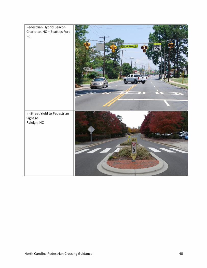
North Carolina Pedestrian Crossing Guidance 40
Pedestrian Hybrid Beacon Charlotte, NC – Beatties Ford Rd.
In-Street Yield to Pedestrian Signage Raleigh, NC
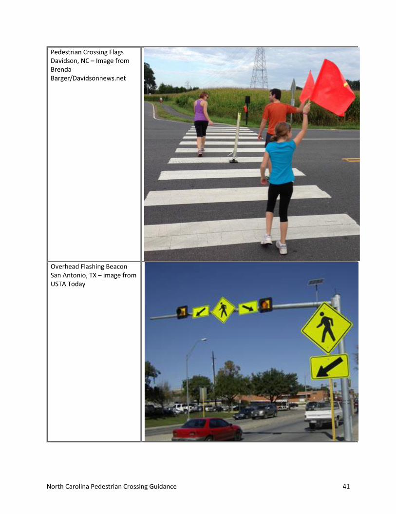
North Carolina Pedestrian Crossing Guidance 41
Pedestrian Crossing Flags Davidson, NC – Image from Brenda Barger/Davidsonnews.net
Overhead Flashing Beacon San Antonio, TX – image from USTA Today
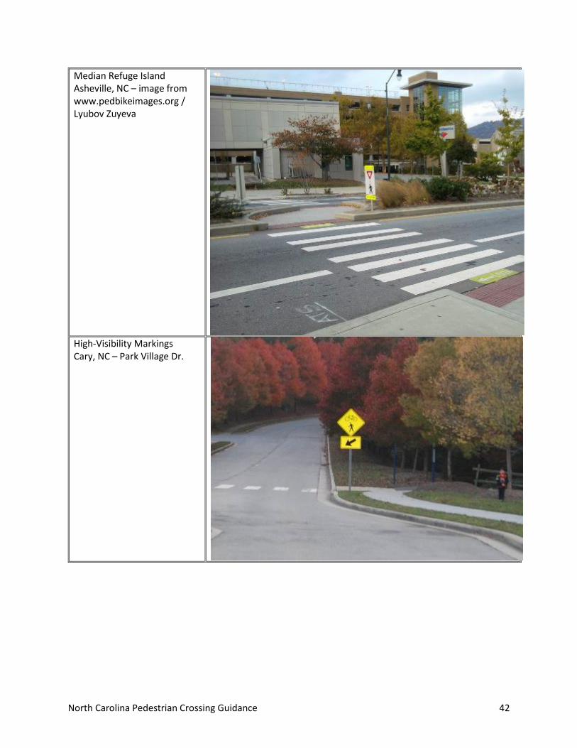
North Carolina Pedestrian Crossing Guidance 42
Median Refuge Island Asheville, NC – image from www.pedbikeimages.org / Lyubov Zuyeva
High-Visibility Markings Cary, NC – Park Village Dr.
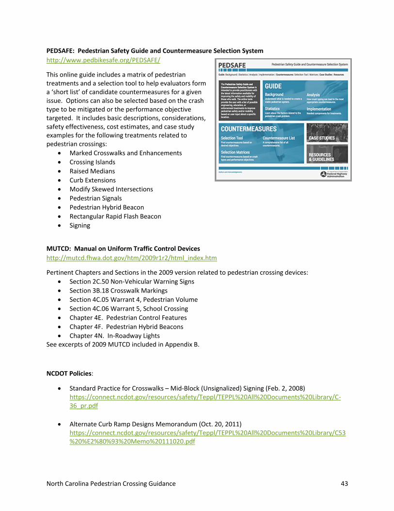
North Carolina Pedestrian Crossing Guidance 43
PEDSAFE: Pedestrian Safety Guide and Countermeasure Selection System
http://www.pedbikesafe.org/PEDSAFE/
This online guide includes a matrix of pedestrian treatments and a selection tool to help evaluators form a ‘short list’ of candidate countermeasures for a given issue. Options can also be selected based on the crash type to be mitigated or the performance objective targeted. It includes basic descriptions, considerations, safety effectiveness, cost estimates, and case study examples for the following treatments related to pedestrian crossings:
Marked Crosswalks and Enhancements
Crossing Islands
Raised Medians
Curb Extensions
Modify Skewed Intersections
Pedestrian Signals
Pedestrian Hybrid Beacon
Rectangular Rapid Flash Beacon
Signing
MUTCD: Manual on Uniform Traffic Control Devices
http://mutcd.fhwa.dot.gov/htm/2009r1r2/html_index.htm
Pertinent Chapters and Sections in the 2009 version related to pedestrian crossing devices:
Section 2C.50 Non-Vehicular Warning Signs
Section 3B.18 Crosswalk Markings
Section 4C.05 Warrant 4, Pedestrian Volume
Section 4C.06 Warrant 5, School Crossing
Chapter 4E. Pedestrian Control Features
Chapter 4F. Pedestrian Hybrid Beacons
Chapter 4N. In-Roadway Lights See excerpts of 2009 MUTCD included in Appendix B.
NCDOT Policies:
Standard Practice for Crosswalks – Mid-Block (Unsignalized) Signing (Feb. 2, 2008) https://connect.ncdot.gov/resources/safety/Teppl/TEPPL%20All%20Documents%20Library/C-36_pr.pdf
Alternate Curb Ramp Designs Memorandum (Oct. 20, 2011) https://connect.ncdot.gov/resources/safety/Teppl/TEPPL%20All%20Documents%20Library/C53%20%E2%80%93%20Memo%20111020.pdf
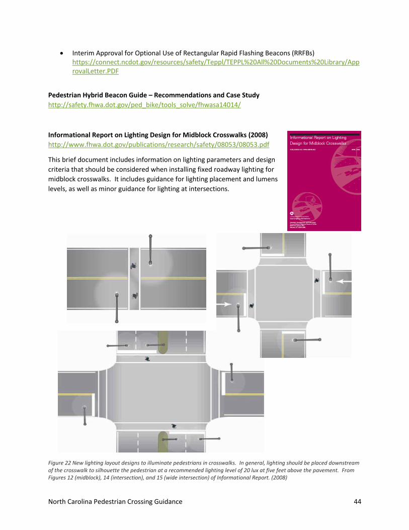
North Carolina Pedestrian Crossing Guidance 44
Interim Approval for Optional Use of Rectangular Rapid Flashing Beacons (RRFBs) https://connect.ncdot.gov/resources/safety/Teppl/TEPPL%20All%20Documents%20Library/ApprovalLetter.PDF
Pedestrian Hybrid Beacon Guide – Recommendations and Case Study
http://safety.fhwa.dot.gov/ped_bike/tools_solve/fhwasa14014/
Informational Report on Lighting Design for Midblock Crosswalks (2008)
http://www.fhwa.dot.gov/publications/research/safety/08053/08053.pdf
This brief document includes information on lighting parameters and design
criteria that should be considered when installing fixed roadway lighting for
midblock crosswalks. It includes guidance for lighting placement and lumens
levels, as well as minor guidance for lighting at intersections.
Figure 22 New lighting layout designs to illuminate pedestrians in crosswalks. In general, lighting should be placed downstream of the crosswalk to silhouette the pedestrian at a recommended lighting level of 20 lux at five feet above the pavement. From Figures 12 (midblock), 14 (intersection), and 15 (wide intersection) of Informational Report. (2008)
North Carolina Pedestrian Crossing Guidance 45
Appendix B. EXCERPTS FROM THE 2009 MUTCD
The following pages include excerpts from the MUTCD of the following sections or full chapters:
Section 4C.05 Warrant 4, Pedestrian Volume
Section 4C.06 Warrant 5, School Crossing
Chapter 4E. Pedestrian Control Features
Chapter 4F. Pedestrian Hybrid Beacons
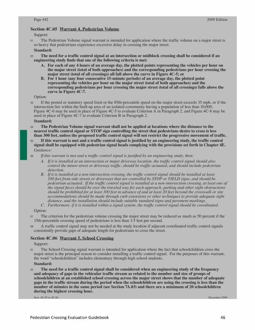
Page 442 2009 Edition
Section 4C.05 Warrant 4, Pedestrian VolumeSupport:
01 The Pedestrian Volume signal warrant is intended for application where the traffic volume on a major street is so heavy that pedestrians experience excessive delay in crossing the major street.Standard:
02 The need for a traffic control signal at an intersection or midblock crossing shall be considered if an engineering study finds that one of the following criteria is met: A. For each of any 4 hours of an average day, the plotted points representing the vehicles per hour on
the major street (total of both approaches) and the corresponding pedestrians per hour crossing the major street (total of all crossings) all fall above the curve in Figure 4C-5; or
B. For 1 hour (any four consecutive 15-minute periods) of an average day, the plotted point representing the vehicles per hour on the major street (total of both approaches) and the corresponding pedestrians per hour crossing the major street (total of all crossings) falls above the curve in Figure 4C-7.
Option:03 If the posted or statutory speed limit or the 85th-percentile speed on the major street exceeds 35 mph, or if the
intersection lies within the built-up area of an isolated community having a population of less than 10,000, Figure 4C-6 may be used in place of Figure 4C-5 to evaluate Criterion A in Paragraph 2, and Figure 4C-8 may be used in place of Figure 4C-7 to evaluate Criterion B in Paragraph 2.Standard:
04 The Pedestrian Volume signal warrant shall not be applied at locations where the distance to the nearest traffic control signal or STOP sign controlling the street that pedestrians desire to cross is less than 300 feet, unless the proposed traffic control signal will not restrict the progressive movement of traffic.
05 If this warrant is met and a traffic control signal is justified by an engineering study, the traffic control signal shall be equipped with pedestrian signal heads complying with the provisions set forth in Chapter 4E.Guidance:
06 If this warrant is met and a traffic control signal is justified by an engineering study, then: A. If it is installed at an intersection or major driveway location, the traffic control signal should also
control the minor-street or driveway traffic, should be traffic-actuated, and should include pedestrian detection.
B. If it is installed at a non-intersection crossing, the traffic control signal should be installed at least 100 feet from side streets or driveways that are controlled by STOP or YIELD signs, and should be pedestrian-actuated. If the traffic control signal is installed at a non-intersection crossing, at least one of the signal faces should be over the traveled way for each approach, parking and other sight obstructions should be prohibited for at least 100 feet in advance of and at least 20 feet beyond the crosswalk or site accommodations should be made through curb extensions or other techniques to provide adequate sight distance, and the installation should include suitable standard signs and pavement markings.
C. Furthermore, if it is installed within a signal system, the traffic control signal should be coordinated.Option:
07 The criterion for the pedestrian volume crossing the major street may be reduced as much as 50 percent if the 15th-percentile crossing speed of pedestrians is less than 3.5 feet per second.
08 A traffic control signal may not be needed at the study location if adjacent coordinated traffic control signals consistently provide gaps of adequate length for pedestrians to cross the street.
Section 4C.06 Warrant 5, School CrossingSupport:
01 The School Crossing signal warrant is intended for application where the fact that schoolchildren cross the major street is the principal reason to consider installing a traffic control signal. For the purposes of this warrant, the word “schoolchildren” includes elementary through high school students.Standard:
02 The need for a traffic control signal shall be considered when an engineering study of the frequency and adequacy of gaps in the vehicular traffic stream as related to the number and size of groups of schoolchildren at an established school crossing across the major street shows that the number of adequate gaps in the traffic stream during the period when the schoolchildren are using the crossing is less than the number of minutes in the same period (see Section 7A.03) and there are a minimum of 20 schoolchildren during the highest crossing hour.Sect. 4C.05 to 4C.06 December 2009
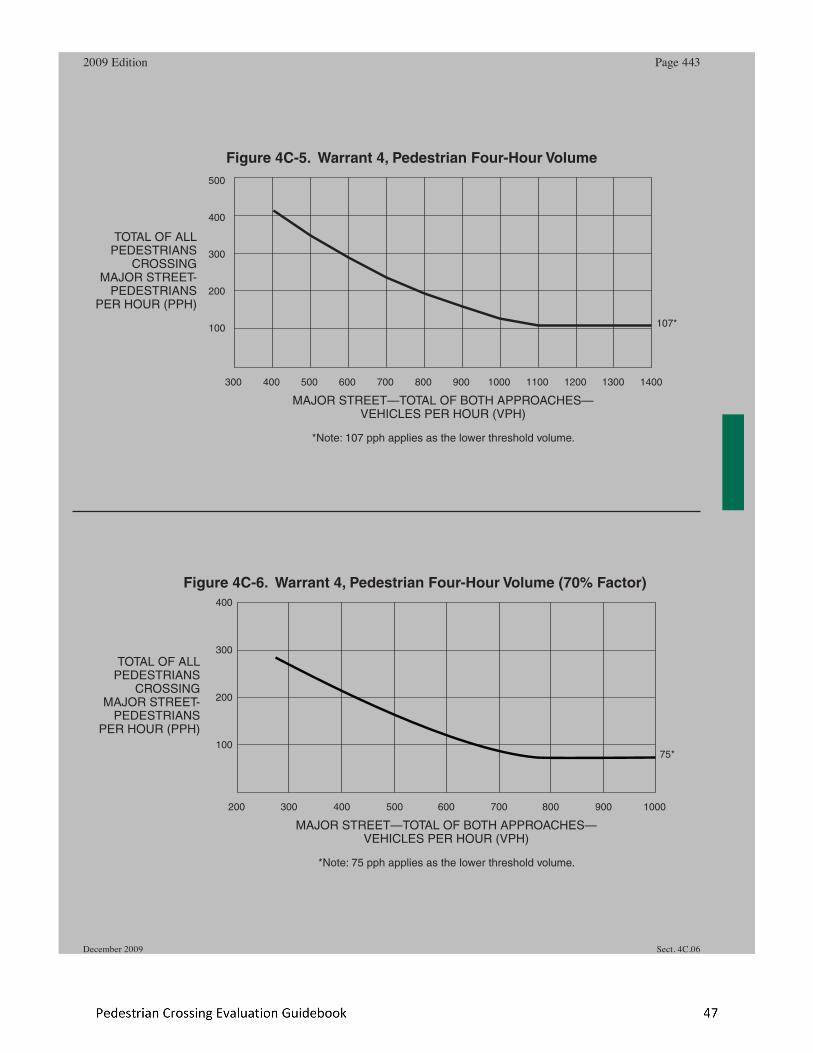
2009 Edition Page 443
300 400 500 600 700 800 900 1000 1100 1200 1300 1400
100
200
300
400
500
TOTAL OF ALLPEDESTRIANS
CROSSINGMAJOR STREET-
PEDESTRIANSPER HOUR (PPH)
107*
MAJOR STREET—TOTAL OF BOTH APPROACHES—VEHICLES PER HOUR (VPH)
*Note: 107 pph applies as the lower threshold volume.
Figure 4C-5. Warrant 4, Pedestrian Four-Hour Volume
200 1000
100
200
300
400
TOTAL OF ALLPEDESTRIANS
CROSSINGMAJOR STREET-
PEDESTRIANSPER HOUR (PPH)
75*
MAJOR STREET—TOTAL OF BOTH APPROACHES—VEHICLES PER HOUR (VPH)
*Note: 75 pph applies as the lower threshold volume.
400 500300 600 800700 900
Figure 4C-6. Warrant 4, Pedestrian Four-Hour Volume (70% Factor)
December 2009 Sect. 4C.06
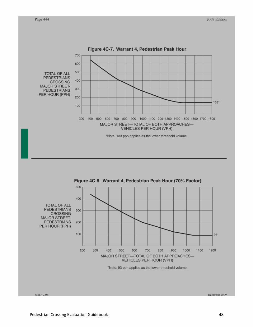
Page 444 2009 Edition
300 1800
100
200
300
400
500
600
700
TOTAL OF ALLPEDESTRIANS
CROSSINGMAJOR STREET-
PEDESTRIANSPER HOUR (PPH)
133*
MAJOR STREET—TOTAL OF BOTH APPROACHES—VEHICLES PER HOUR (VPH)
*Note: 133 pph applies as the lower threshold volume.
600 700 800500400 900 1000 1100 1200 15001300 16001400 1700
Figure 4C-7. Warrant 4, Pedestrian Peak Hour
100
200
300
400
500
TOTAL OF ALLPEDESTRIANS
CROSSINGMAJOR STREET-
PEDESTRIANSPER HOUR (PPH)
93*
MAJOR STREET—TOTAL OF BOTH APPROACHES—VEHICLES PER HOUR (VPH)
*Note: 93 pph applies as the lower threshold volume.
200 400300 600 800 1000500 700 900 1100 1200
Figure 4C-8. Warrant 4, Pedestrian Peak Hour (70% Factor)
Sect. 4C.06 December 2009
2009 Edition Page 445
03 Before a decision is made to install a traffic control signal, consideration shall be given to the implementation of other remedial measures, such as warning signs and flashers, school speed zones, school crossing guards, or a grade-separated crossing.
04 The School Crossing signal warrant shall not be applied at locations where the distance to the nearest traffic control signal along the major street is less than 300 feet, unless the proposed traffic control signal will not restrict the progressive movement of traffic.Guidance:
05 If this warrant is met and a traffic control signal is justified by an engineering study, then: A. If it is installed at an intersection or major driveway location, the traffic control signal should
also control the minor-street or driveway traffic, should be traffic-actuated, and should include pedestrian detection.
B. If it is installed at a non-intersection crossing, the traffic control signal should be installed at least 100 feet from side streets or driveways that are controlled by STOP or YIELD signs, and should be pedestrian-actuated. If the traffic control signal is installed at a non-intersection crossing, at least one of the signal faces should be over the traveled way for each approach, parking and other sight obstructions should be prohibited for at least 100 feet in advance of and at least 20 feet beyond the crosswalk or site accommodations should be made through curb extensions or other techniques to provide adequate sight distance, and the installation should include suitable standard signs and pavement markings.
C. Furthermore, if it is installed within a signal system, the traffic control signal should be coordinated.
Section 4C.07 Warrant 6, Coordinated Signal SystemSupport:
01 Progressive movement in a coordinated signal system sometimes necessitates installing traffic control signals at intersections where they would not otherwise be needed in order to maintain proper platooning of vehicles.Standard:
02 The need for a traffic control signal shall be considered if an engineering study finds that one of the following criteria is met: A. On a one-way street or a street that has traffic predominantly in one direction, the adjacent
traffic control signals are so far apart that they do not provide the necessary degree of vehicular platooning.
B. On a two-way street, adjacent traffic control signals do not provide the necessary degree of platooning and the proposed and adjacent traffic control signals will collectively provide a progressive operation.
Guidance:03 The Coordinated Signal System signal warrant should not be applied where the resultant spacing of traffic
control signals would be less than 1,000 feet.
Section 4C.08 Warrant 7, Crash ExperienceSupport:
01 The Crash Experience signal warrant conditions are intended for application where the severity and frequency of crashes are the principal reasons to consider installing a traffic control signal.Standard:
02 The need for a traffic control signal shall be considered if an engineering study finds that all of the following criteria are met: A. Adequate trial of alternatives with satisfactory observance and enforcement has failed to reduce the
crash frequency; and B. Five or more reported crashes, of types susceptible to correction by a traffic control signal, have
occurred within a 12-month period, each crash involving personal injury or property damage apparently exceeding the applicable requirements for a reportable crash; and
C. For each of any 8 hours of an average day, the vehicles per hour (vph) given in both of the 80 percent columns of Condition A in Table 4C-1 (see Section 4C.02), or the vph in both of the 80 percent columns of Condition B in Table 4C-1 exists on the major-street and the higher-volume minor-street approach, respectively, to the intersection, or the volume of pedestrian traffic is not less than 80 percent of the requirements specified in the Pedestrian Volume warrant. These major-street and minor-street volumes shall be for the same 8 hours. On the minor street, the higher volume shall not be required to be on the same approach during each of the 8 hours.
December 2009 Sect. 4C.06 to 4C.08
2009 Edition Page 495
CHAPTER 4E. PEDESTRIAN CONTROL FEATURES
Section 4E.01 Pedestrian Signal HeadsSupport:
01 Pedestrian signal heads provide special types of traffic signal indications exclusively intended for controlling pedestrian traffic. These signal indications consist of the illuminated symbols of a WALKING PERSON (symbolizing WALK) and an UPRAISED HAND (symbolizing DONT WALK).Guidance:
02 Engineering judgment should determine the need for separate pedestrian signal heads (see Section 4D.03) and accessible pedestrian signals (see Section 4E.09).Support:
03 Chapter 4F contains information regarding the use of pedestrian hybrid beacons and Chapter 4N contains information regarding the use of In-Roadway Warning Lights at unsignalized marked crosswalks.
Section 4E.02 Meaning of Pedestrian Signal Head IndicationsStandard:
01 Pedestrian signal head indications shall have the following meanings: A. A steady WALKING PERSON (symbolizing WALK) signal indication means that a pedestrian
facing the signal indication is permitted to start to cross the roadway in the direction of the signal indication, possibly in conflict with turning vehicles. The pedestrian shall yield the right-of-way to vehicles lawfully within the intersection at the time that the WALKING PERSON (symbolizing WALK) signal indication is first shown.
B. A flashing UPRAISED HAND (symbolizing DONT WALK) signal indication means that a pedestrian shall not start to cross the roadway in the direction of the signal indication, but that any pedestrian who has already started to cross on a steady WALKING PERSON (symbolizing WALK) signal indication shall proceed to the far side of the traveled way of the street or highway, unless otherwise directed by a traffic control device to proceed only to the median of a divided highway or only to some other island or pedestrian refuge area.
C. A steady UPRAISED HAND (symbolizing DONT WALK) signal indication means that a pedestrian shall not enter the roadway in the direction of the signal indication.
D. A flashing WALKING PERSON (symbolizing WALK) signal indication has no meaning and shall not be used.
Section 4E.03 Application of Pedestrian Signal HeadsStandard:
01 Pedestrian signal heads shall be used in conjunction with vehicular traffic control signals under any of the following conditions: A. If a traffic control signal is justified by an engineering study and meets either Warrant 4, Pedestrian
Volume or Warrant 5, School Crossing (see Chapter 4C); B. If an exclusive signal phase is provided or made available for pedestrian movements in one or more
directions, with all conflicting vehicular movements being stopped; C. At an established school crossing at any signalized location; or D. Where engineering judgment determines that multi-phase signal indications (as with split-phase
timing) would tend to confuse or cause conflicts with pedestrians using a crosswalk guided only by vehicular signal indications.
Guidance:02 Pedestrian signal heads should be used under any of the following conditions:
A. If it is necessary to assist pedestrians in deciding when to begin crossing the roadway in the chosen direction or if engineering judgment determines that pedestrian signal heads are justified to minimize vehicle-pedestrian conflicts;
B. If pedestrians are permitted to cross a portion of a street, such as to or from a median of sufficient width for pedestrians to wait, during a particular interval but are not permitted to cross the remainder of the street during any part of the same interval; and/or
C. If no vehicular signal indications are visible to pedestrians, or if the vehicular signal indications that are visible to pedestrians starting a crossing provide insufficient guidance for them to decide when to begin crossing the roadway in the chosen direction, such as on one-way streets, at T-intersections, or at multi-phase signal operations.
December 2009 Sect. 4E.01 to 4E.03
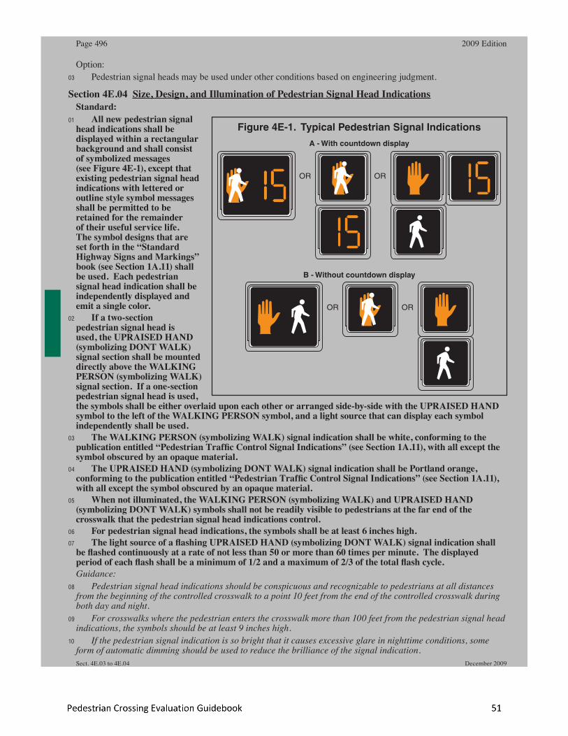
Page 496 2009 Edition
Option:03 Pedestrian signal heads may be used under other conditions based on engineering judgment.
Section 4E.04 Size, Design, and Illumination of Pedestrian Signal Head IndicationsStandard:
01 All new pedestrian signal head indications shall be displayed within a rectangular background and shall consist of symbolized messages (see Figure 4E-1), except that existing pedestrian signal head indications with lettered or outline style symbol messages shall be permitted to be retained for the remainder of their useful service life. The symbol designs that are set forth in the “Standard Highway Signs and Markings” book (see Section 1A.11) shall be used. Each pedestrian signal head indication shall be independently displayed and emit a single color.
02 If a two-section pedestrian signal head is used, the UPRAISED HAND (symbolizing DONT WALK) signal section shall be mounted directly above the WALKING PERSON (symbolizing WALK) signal section. If a one-section pedestrian signal head is used, the symbols shall be either overlaid upon each other or arranged side-by-side with the UPRAISED HAND symbol to the left of the WALKING PERSON symbol, and a light source that can display each symbol independently shall be used.
03 The WALKING PERSON (symbolizing WALK) signal indication shall be white, conforming to the publication entitled “Pedestrian Traffic Control Signal Indications” (see Section 1A.11), with all except the symbol obscured by an opaque material.
04 The UPRAISED HAND (symbolizing DONT WALK) signal indication shall be Portland orange, conforming to the publication entitled “Pedestrian Traffic Control Signal Indications” (see Section 1A.11), with all except the symbol obscured by an opaque material.
05 When not illuminated, the WALKING PERSON (symbolizing WALK) and UPRAISED HAND (symbolizing DONT WALK) symbols shall not be readily visible to pedestrians at the far end of the crosswalk that the pedestrian signal head indications control.
06 For pedestrian signal head indications, the symbols shall be at least 6 inches high.07 The light source of a flashing UPRAISED HAND (symbolizing DONT WALK) signal indication shall
be flashed continuously at a rate of not less than 50 or more than 60 times per minute. The displayed period of each flash shall be a minimum of 1/2 and a maximum of 2/3 of the total flash cycle.Guidance:
08 Pedestrian signal head indications should be conspicuous and recognizable to pedestrians at all distances from the beginning of the controlled crosswalk to a point 10 feet from the end of the controlled crosswalk during both day and night.
09 For crosswalks where the pedestrian enters the crosswalk more than 100 feet from the pedestrian signal head indications, the symbols should be at least 9 inches high.
10 If the pedestrian signal indication is so bright that it causes excessive glare in nighttime conditions, some form of automatic dimming should be used to reduce the brilliance of the signal indication.
B - Without countdown display
A - With countdown display
Figure 4E-1. Typical Pedestrian Signal Indications
OR OR
OR OR
Sect. 4E.03 to 4E.04 December 2009
2009 Edition Page 497
Option:11 An animated eyes symbol may be added to a pedestrian signal head in order to prompt pedestrians to look for
vehicles in the intersection during the time that the WALKING PERSON (symbolizing WALK) signal indication is displayed.Standard:
12 If used, the animated eyes symbol shall consist of an outline of a pair of white steadily-illuminated eyes with white eyeballs that scan from side to side at a rate of approximately once per second. The animated eyes symbol shall be at least 12 inches wide with each eye having a width of at least 5 inches and a height of at least 2.5 inches. The animated eyes symbol shall be illuminated at the start of the walk interval and shall terminate at the end of the walk interval.
Section 4E.05 Location and Height of Pedestrian Signal HeadsStandard:
01 Pedestrian signal heads shall be mounted with the bottom of the signal housing including brackets not less than 7 feet or more than 10 feet above sidewalk level, and shall be positioned and adjusted to provide maximum visibility at the beginning of the controlled crosswalk.
02 If pedestrian signal heads are mounted on the same support as vehicular signal heads, there shall be a physical separation between them.
Section 4E.06 Pedestrian Intervals and Signal PhasesStandard:
01 At intersections equipped with pedestrian signal heads, the pedestrian signal indications shall be displayed except when the vehicular traffic control signal is being operated in the flashing mode. At those times, the pedestrian signal indications shall not be displayed.
02 When the pedestrian signal heads associated with a crosswalk are displaying either a steady WALKING PERSON (symbolizing WALK) or a flashing UPRAISED HAND (symbolizing DONT WALK) signal indication, a steady or a flashing red signal indication shall be shown to any conflicting vehicular movement that is approaching the intersection or midblock location perpendicular or nearly perpendicular to the crosswalk.
03 When pedestrian signal heads are used, a WALKING PERSON (symbolizing WALK) signal indication shall be displayed only when pedestrians are permitted to leave the curb or shoulder.
04 A pedestrian change interval consisting of a flashing UPRAISED HAND (symbolizing DONT WALK) signal indication shall begin immediately following the WALKING PERSON (symbolizing WALK) signal indication. Following the pedestrian change interval, a buffer interval consisting of a steady UPRAISED HAND (symbolizing DONT WALK) signal indication shall be displayed for at least 3 seconds prior to the release of any conflicting vehicular movement. The sum of the time of the pedestrian change interval and the buffer interval shall not be less than the calculated pedestrian clearance time (see Paragraphs 7 through 16). The buffer interval shall not begin later than the beginning of the red clearance interval, if used.Option:
05 During the yellow change interval, the UPRAISED HAND (symbolizing DON’T WALK) signal indication may be displayed as either a flashing indication, a steady indication, or a flashing indication for an initial portion of the yellow change interval and a steady indication for the remainder of the interval.Support:
06 Figure 4E-2 illustrates the pedestrian intervals and their possible relationships with associated vehicular signal phase intervals.Guidance:
07 Except as provided in Paragraph 8, the pedestrian clearance time should be sufficient to allow a pedestrian crossing in the crosswalk who left the curb or shoulder at the end of the WALKING PERSON (symbolizing WALK) signal indication to travel at a walking speed of 3.5 feet per second to at least the far side of the traveled way or to a median of sufficient width for pedestrians to wait.Option:
08 A walking speed of up to 4 feet per second may be used to evaluate the sufficiency of the pedestrian clearance time at locations where an extended pushbutton press function has been installed to provide slower pedestrians an opportunity to request and receive a longer pedestrian clearance time. Passive pedestrian detection may also be used to automatically adjust the pedestrian clearance time based on the pedestrian’s actual walking speed or actual clearance of the crosswalk.December 2009 Sect. 4E.04 to 4E.06
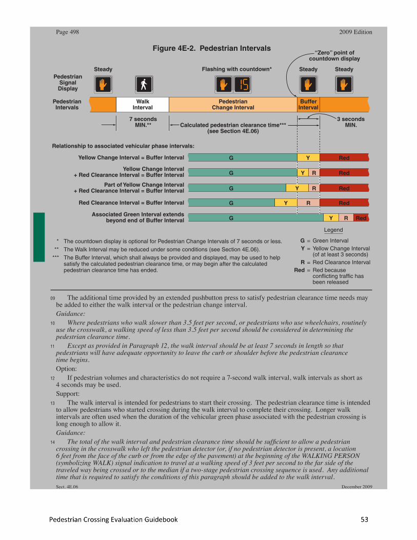
Page 498 2009 Edition
09 The additional time provided by an extended pushbutton press to satisfy pedestrian clearance time needs may be added to either the walk interval or the pedestrian change interval.Guidance:
10 Where pedestrians who walk slower than 3.5 feet per second, or pedestrians who use wheelchairs, routinely use the crosswalk, a walking speed of less than 3.5 feet per second should be considered in determining the pedestrian clearance time.
11 Except as provided in Paragraph 12, the walk interval should be at least 7 seconds in length so that pedestrians will have adequate opportunity to leave the curb or shoulder before the pedestrian clearance time begins.Option:
12 If pedestrian volumes and characteristics do not require a 7-second walk interval, walk intervals as short as 4 seconds may be used.Support:
13 The walk interval is intended for pedestrians to start their crossing. The pedestrian clearance time is intended to allow pedestrians who started crossing during the walk interval to complete their crossing. Longer walk intervals are often used when the duration of the vehicular green phase associated with the pedestrian crossing is long enough to allow it.Guidance:
14 The total of the walk interval and pedestrian clearance time should be sufficient to allow a pedestrian crossing in the crosswalk who left the pedestrian detector (or, if no pedestrian detector is present, a location 6 feet from the face of the curb or from the edge of the pavement) at the beginning of the WALKING PERSON (symbolizing WALK) signal indication to travel at a walking speed of 3 feet per second to the far side of the traveled way being crossed or to the median if a two-stage pedestrian crossing sequence is used. Any additional time that is required to satisfy the conditions of this paragraph should be added to the walk interval.
Figure 4E-2. Pedestrian Intervals
G = Green Interval Y = Yellow Change Interval (of at least 3 seconds) R = Red Clearance Interval Red = Red because conflicting traffic has been released
* The countdown display is optional for Pedestrian Change Intervals of 7 seconds or less. ** The Walk Interval may be reduced under some conditions (see Section 4E.06). *** The Buffer Interval, which shall always be provided and displayed, may be used to help
satisfy the calculated pedestrian clearance time, or may begin after the calculated pedestrian clearance time has ended.
PedestrianSignalDisplay
PedestrianIntervals
Relationship to associated vehicular phase intervals:
Yellow Change Interval = Buffer Interval
7 secondsMIN.**
3 secondsMIN.
“Zero” point of countdown display
Calculated pedestrian clearance time***(see Section 4E.06)
Steady Steady SteadyFlashing with countdown*
WalkInterval
BufferInterval
PedestrianChange Interval
Y RedG
Yellow Change Interval+ Red Clearance Interval = Buffer Interval
Part of Yellow Change Interval+ Red Clearance Interval = Buffer Interval
Y R RedG
Y R RedG
Red Clearance Interval = Buffer Interval Y R RedG
Associated Green Interval extends beyond end of Buffer Interval Y R RedG
Legend
Sect. 4E.06 December 2009

2009 Edition Page 499
Option:15 On a street with a median of sufficient width for pedestrians to wait, a pedestrian clearance time that allows
the pedestrian to cross only from the curb or shoulder to the median may be provided.Standard:
16 Where the pedestrian clearance time is sufficient only for crossing from the curb or shoulder to a median of sufficient width for pedestrians to wait, median-mounted pedestrian signals (with pedestrian detectors if actuated operation is used) shall be provided (see Sections 4E.08 and 4E.09) and signing such as the R10-3d sign (see Section 2B.52) shall be provided to notify pedestrians to cross only to the median to await the next WALKING PERSON (symbolizing WALK) signal indication.Guidance:
17 Where median-mounted pedestrian signals and detectors are provided, the use of accessible pedestrian signals (see Sections 4E.09 through 4E.13) should be considered.Option:
18 During the transition into preemption, the walk interval and the pedestrian change interval may be shortened or omitted as described in Section 4D.27.
19 At intersections with high pedestrian volumes and high conflicting turning vehicle volumes, a brief leading pedestrian interval, during which an advance WALKING PERSON (symbolizing WALK) indication is displayed for the crosswalk while red indications continue to be displayed to parallel through and/or turning traffic, may be used to reduce conflicts between pedestrians and turning vehicles.Guidance:
20 If a leading pedestrian interval is used, the use of accessible pedestrian signals (see Sections 4E.09 through 4E.13) should be considered.Support:
21 If a leading pedestrian interval is used without accessible features, pedestrians who are visually impaired can be expected to begin crossing at the onset of the vehicular movement when drivers are not expecting them to begin crossing.Guidance:
22 If a leading pedestrian interval is used, it should be at least 3 seconds in duration and should be timed to allow pedestrians to cross at least one lane of traffic or, in the case of a large corner radius, to travel far enough for pedestrians to establish their position ahead of the turning traffic before the turning traffic is released.
23 If a leading pedestrian interval is used, consideration should be given to prohibiting turns across the crosswalk during the leading pedestrian interval.Support:
24 At intersections with pedestrian volumes that are so high that drivers have difficulty finding an opportunity to turn across the crosswalk, the duration of the green interval for a parallel concurrent vehicular movement is sometimes intentionally set to extend beyond the pedestrian clearance time to provide turning drivers additional green time to make their turns while the pedestrian signal head is displaying a steady UPRAISED HAND (symbolizing DONT WALK) signal indication after pedestrians have had time to complete their crossings.
Section 4E.07 Countdown Pedestrian SignalsStandard:
01 All pedestrian signal heads used at crosswalks where the pedestrian change interval is more than 7 seconds shall include a pedestrian change interval countdown display in order to inform pedestrians of the number of seconds remaining in the pedestrian change interval.Option:
02 Pedestrian signal heads used at crosswalks where the pedestrian change interval is 7 seconds or less may include a pedestrian change interval countdown display in order to inform pedestrians of the number of seconds remaining in the pedestrian change interval.Standard:
03 Where countdown pedestrian signals are used, the countdown shall always be displayed simultaneously with the flashing UPRAISED HAND (symbolizing DONT WALK) signal indication displayed for that crosswalk.
04 Countdown pedestrian signals shall consist of Portland orange numbers that are at least 6 inches in height on a black opaque background. The countdown pedestrian signal shall be located immediately adjacent to the associated UPRAISED HAND (symbolizing DONT WALK) pedestrian signal head indication (see Figure 4E-1).December 2009 Sect. 4E.06 to 4E.07
Page 500 2009 Edition
05 The display of the number of remaining seconds shall begin only at the beginning of the pedestrian change interval (flashing UPRAISED HAND). After the countdown displays zero, the display shall remain dark until the beginning of the next countdown.
06 The countdown pedestrian signal shall display the number of seconds remaining until the termination of the pedestrian change interval (flashing UPRAISED HAND). Countdown displays shall not be used during the walk interval or during the red clearance interval of a concurrent vehicular phase.Guidance:
07 If used with a pedestrian signal head that does not have a concurrent vehicular phase, the pedestrian change interval (flashing UPRAISED HAND) should be set to be approximately 4 seconds less than the required pedestrian clearance time (see Section 4E.06) and an additional clearance interval (during which a steady UPRAISED HAND is displayed) should be provided prior to the start of the conflicting vehicular phase.
08 For crosswalks where the pedestrian enters the crosswalk more than 100 feet from the countdown pedestrian signal display, the numbers should be at least 9 inches in height.
09 Because some technology includes the countdown pedestrian signal logic in a separate timing device that is independent of the timing in the traffic signal controller, care should be exercised by the engineer when timing changes are made to pedestrian change intervals.
10 If the pedestrian change interval is interrupted or shortened as a part of a transition into a preemption sequence (see Section 4E.06), the countdown pedestrian signal display should be discontinued and go dark immediately upon activation of the preemption transition.
Section 4E.08 Pedestrian DetectorsOption:
01 Pedestrian detectors may be pushbuttons or passive detection devices.Support:
02 Passive detection devices register the presence of a pedestrian in a position indicative of a desire to cross, without requiring the pedestrian to push a button. Some passive detection devices are capable of tracking the progress of a pedestrian as the pedestrian crosses the roadway for the purpose of extending or shortening the duration of certain pedestrian timing intervals.
03 The provisions in this Section place pedestrian pushbuttons within easy reach of pedestrians who are intending to cross each crosswalk and make it obvious which pushbutton is associated with each crosswalk. These provisions also position pushbutton poles in optimal locations for installation of accessible pedestrian signals (see Sections 4E.09 through 4E.13). Information regarding reach ranges can be found in the “Americans with Disabilities Act Accessibility Guidelines for Buildings and Facilities (ADAAG)” (see Section 1A.11).Guidance:
04 If pedestrian pushbuttons are used, they should be capable of easy activation and conveniently located near each end of the crosswalks. Except as provided in Paragraphs 5 and 6, pedestrian pushbuttons should be located to meet all of the following criteria (see Figure 4E-3): A. Unobstructed and adjacent to a level all-weather surface to provide access from a wheelchair; B. Where there is an all-weather surface, a wheelchair accessible route from the pushbutton to the ramp; C. Between the edge of the crosswalk line (extended) farthest from the center of the intersection and the side
of a curb ramp (if present), but not greater than 5 feet from said crosswalk line; D. Between 1.5 and 6 feet from the edge of the curb, shoulder, or pavement; E. With the face of the pushbutton parallel to the crosswalk to be used; and F. At a mounting height of approximately 3.5 feet, but no more than 4 feet, above the sidewalk.
05 Where there are physical constraints that make it impractical to place the pedestrian pushbutton adjacent to a level all-weather surface, the surface should be as level as feasible.
06 Where there are physical constraints that make it impractical to place the pedestrian pushbutton between 1.5 and 6 feet from the edge of the curb, shoulder, or pavement, it should not be farther than 10 feet from the edge of curb, shoulder, or pavement.
07 Except as provided in Paragraph 8, where two pedestrian pushbuttons are provided on the same corner of a signalized location, the pushbuttons should be separated by a distance of at least 10 feet.Option:
08 Where there are physical constraints on a particular corner that make it impractical to provide the 10-foot separation between the two pedestrian pushbuttons, the pushbuttons may be placed closer together or on the same pole.
Sect. 4E.07 to 4E.08 December 2009
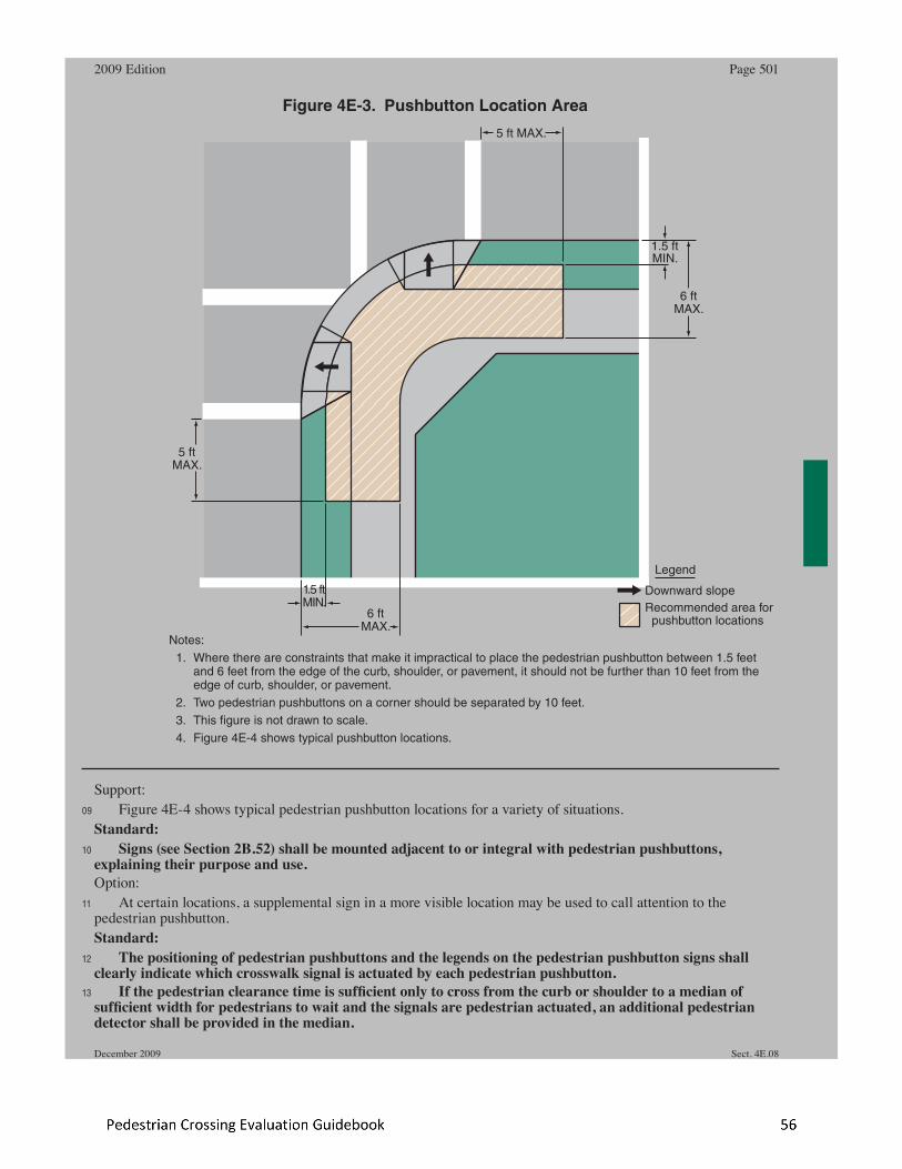
2009 Edition Page 501
Support:09 Figure 4E-4 shows typical pedestrian pushbutton locations for a variety of situations.
Standard:10 Signs (see Section 2B.52) shall be mounted adjacent to or integral with pedestrian pushbuttons,
explaining their purpose and use.Option:
11 At certain locations, a supplemental sign in a more visible location may be used to call attention to the pedestrian pushbutton.Standard:
12 The positioning of pedestrian pushbuttons and the legends on the pedestrian pushbutton signs shall clearly indicate which crosswalk signal is actuated by each pedestrian pushbutton.
13 If the pedestrian clearance time is sufficient only to cross from the curb or shoulder to a median of sufficient width for pedestrians to wait and the signals are pedestrian actuated, an additional pedestrian detector shall be provided in the median.
5 ft MAX.
5 ftMAX.
Notes: 1. Where there are constraints that make it impractical to place the pedestrian pushbutton between 1.5 feet
and 6 feet from the edge of the curb, shoulder, or pavement, it should not be further than 10 feet from the edge of curb, shoulder, or pavement.
2. Two pedestrian pushbuttons on a corner should be separated by 10 feet. 3. This figure is not drawn to scale. 4. Figure 4E-4 shows typical pushbutton locations.
1.5 ftMIN.
6 ftMAX.
1.5 ftMIN.
6 ftMAX.
Legend
Downward slopeRecommended area for pushbutton locations
Figure 4E-3. Pushbutton Location Area
December 2009 Sect. 4E.08
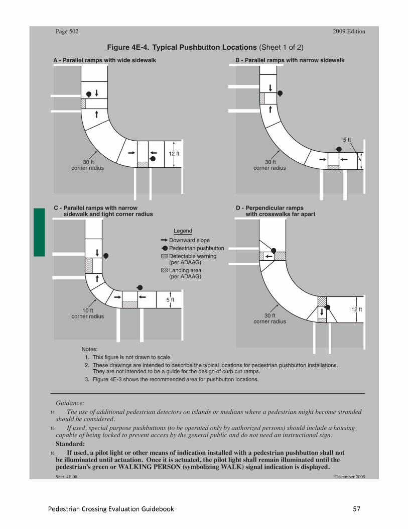
Page 502 2009 Edition
Guidance:14 The use of additional pedestrian detectors on islands or medians where a pedestrian might become stranded
should be considered.15 If used, special purpose pushbuttons (to be operated only by authorized persons) should include a housing
capable of being locked to prevent access by the general public and do not need an instructional sign.Standard:
16 If used, a pilot light or other means of indication installed with a pedestrian pushbutton shall not be illuminated until actuation. Once it is actuated, the pilot light shall remain illuminated until the pedestrian’s green or WALKING PERSON (symbolizing WALK) signal indication is displayed.
Figure 4E-4. Typical Pushbutton Locations (Sheet 1 of 2)
5 ft
10 ftcorner radius
C - Parallel ramps with narrow sidewalk and tight corner radius
12 ft30 ft
corner radius
D - Perpendicular ramps with crosswalks far apart
30 ftcorner radius
12 ft
A - Parallel ramps with wide sidewalk
30 ftcorner radius
5 ft
B - Parallel ramps with narrow sidewalk
Legend
Downward slopePedestrian pushbuttonDetectable warning (per ADAAG)Landing area(per ADAAG)
Notes: 1. This figure is not drawn to scale. 2. These drawings are intended to describe the typical locations for pedestrian pushbutton installations.
They are not intended to be a guide for the design of curb cut ramps. 3. Figure 4E-3 shows the recommended area for pushbutton locations.
Sect. 4E.08 December 2009
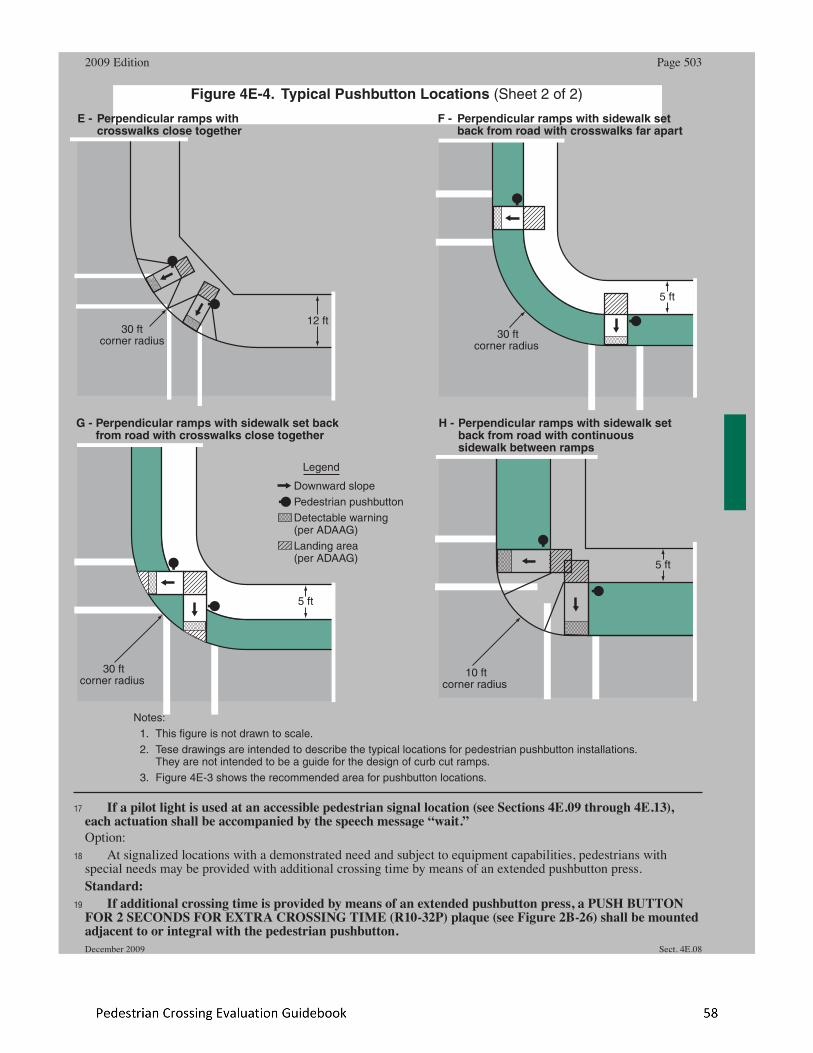
2009 Edition Page 503
17 If a pilot light is used at an accessible pedestrian signal location (see Sections 4E.09 through 4E.13), each actuation shall be accompanied by the speech message “wait.”Option:
18 At signalized locations with a demonstrated need and subject to equipment capabilities, pedestrians with special needs may be provided with additional crossing time by means of an extended pushbutton press.Standard:
19 If additional crossing time is provided by means of an extended pushbutton press, a PUSH BUTTON FOR 2 SECONDS FOR EXTRA CROSSING TIME (R10-32P) plaque (see Figure 2B-26) shall be mounted adjacent to or integral with the pedestrian pushbutton.
Figure 4E-4. Typical Pushbutton Locations (Sheet 2 of 2)
30 ftcorner radius
5 ft
F - Perpendicular ramps with sidewalk setback from road with crosswalks far apart
30 ftcorner radius
5 ft
G - Perpendicular ramps with sidewalk set backfrom road with crosswalks close together
12 ft30 ft
corner radius
E - Perpendicular ramps withcrosswalks close together
H - Perpendicular ramps with sidewalk set back from road with continuous sidewalk between ramps
5 ft
10 ftcorner radius
Notes: 1. This figure is not drawn to scale. 2. Tese drawings are intended to describe the typical locations for pedestrian pushbutton installations.
They are not intended to be a guide for the design of curb cut ramps. 3. Figure 4E-3 shows the recommended area for pushbutton locations.
Legend
Downward slopePedestrian pushbuttonDetectable warning (per ADAAG)Landing area(per ADAAG)
December 2009 Sect. 4E.08
Page 504 2009 Edition
Section 4E.09 Accessible Pedestrian Signals and Detectors – GeneralSupport:
01 Accessible pedestrian signals and detectors provide information in non-visual formats (such as audible tones, speech messages, and/or vibrating surfaces).
02 The primary technique that pedestrians who have visual disabilities use to cross streets at signalized locations is to initiate their crossing when they hear the traffic in front of them stop and the traffic alongside them begin to move, which often corresponds to the onset of the green interval. The existing environment is often not sufficient to provide the information that pedestrians who have visual disabilities need to cross a roadway at a signalized location.Guidance:
03 If a particular signalized location presents difficulties for pedestrians who have visual disabilities to cross the roadway, an engineering study should be conducted that considers the needs of pedestrians in general, as well as the information needs of pedestrians with visual disabilities. The engineering study should consider the following factors: A. Potential demand for accessible pedestrian signals; B. A request for accessible pedestrian signals; C. Traffic volumes during times when pedestrians might be present, including periods of low traffic volumes
or high turn-on-red volumes; D. The complexity of traffic signal phasing (such as split phases, protected turn phases, leading pedestrian
intervals, and exclusive pedestrian phases); and E. The complexity of intersection geometry.Support:
04 The factors that make crossing at a signalized location difficult for pedestrians who have visual disabilities include: increasingly quiet cars, right turn on red (which masks the beginning of the through phase), continuous right-turn movements, complex signal operations, traffic circles, and wide streets. Furthermore, low traffic volumes might make it difficult for pedestrians who have visual disabilities to discern signal phase changes.
05 Local organizations, providing support services to pedestrians who have visual and/or hearing disabilities, can often act as important advisors to the traffic engineer when consideration is being given to the installation of devices to assist such pedestrians. Additionally, orientation and mobility specialists or similar staff also might be able to provide a wide range of advice. The U.S. Access Board (www.access-board.gov) provides technical assistance for making pedestrian signal information available to persons with visual disabilities (see Page i for the address for the U.S. Access Board).Standard:
06 When used, accessible pedestrian signals shall be used in combination with pedestrian signal timing. The information provided by an accessible pedestrian signal shall clearly indicate which pedestrian crossing is served by each device.
07 Under stop-and-go operation, accessible pedestrian signals shall not be limited in operation by the time of day or day of week.Option:
08 Accessible pedestrian signal detectors may be pushbuttons or passive detection devices.09 At locations with pretimed traffic control signals or non-actuated approaches, pedestrian pushbuttons may be
used to activate the accessible pedestrian signals.Support:
10 Accessible pedestrian signals are typically integrated into the pedestrian detector (pushbutton), so the audible tones and/or messages come from the pushbutton housing. They have a pushbutton locator tone and tactile arrow, and can include audible beaconing and other special features.Option:
11 The name of the street to be crossed may also be provided in accessible format, such as Braille or raised print. Tactile maps of crosswalks may also be provided.Support:
12 Specifications regarding the use of Braille or raised print for traffic control devices can be found in the “Americans with Disabilities Act Accessibility Guidelines for Buildings and Facilities (ADAAG)” (see Section 1A.11).
Sect. 4E.09 December 2009
2009 Edition Page 505
Standard:13 At accessible pedestrian signal locations where pedestrian pushbuttons are used, each pushbutton shall
activate both the walk interval and the accessible pedestrian signals.
Section 4E.10 Accessible Pedestrian Signals and Detectors – LocationSupport:
01 Accessible pedestrian signals that are located as close as possible to pedestrians waiting to cross the street provide the clearest and least ambiguous indication of which pedestrian crossing is served by a device.Guidance:
02 Pushbuttons for accessible pedestrian signals should be located in accordance with the provisions of Section 4E.08 and should be located as close as possible to the crosswalk line furthest from the center of the intersection and as close as possible to the curb ramp.Standard:
03 If two accessible pedestrian pushbuttons are placed less than 10 feet apart or on the same pole, each accessible pedestrian pushbutton shall be provided with the following features (see Sections 4E.11 through 4E.13): A. A pushbutton locator tone, B. A tactile arrow, C. A speech walk message for the WALKING PERSON (symbolizing WALK) indication, and D. A speech pushbutton information message.
04 If the pedestrian clearance time is sufficient only to cross from the curb or shoulder to a median of sufficient width for pedestrians to wait and accessible pedestrian detectors are used, an additional accessible pedestrian detector shall be provided in the median.
Section 4E.11 Accessible Pedestrian Signals and Detectors – Walk IndicationsSupport:
01 Technology that provides different sounds for each non-concurrent signal phase has frequently been found to provide ambiguous information. Research indicates that a rapid tick tone for each crossing coming from accessible pedestrian signal devices on separated poles located close to each crosswalk provides unambiguous information to pedestrians who are blind or visually impaired. Vibrotactile indications provide information to pedestrians who are blind and deaf and are also used by pedestrians who are blind or who have low vision to confirm the walk signal in noisy situations.Standard:
02 Accessible pedestrian signals shall have both audible and vibrotactile walk indications.03 Vibrotactile walk indications shall be provided by a tactile arrow on the pushbutton (see Section 4E.12)
that vibrates during the walk interval.04 Accessible pedestrian signals shall have an audible walk indication during the walk interval only. The
audible walk indication shall be audible from the beginning of the associated crosswalk.05 The accessible walk indication shall have the same duration as the pedestrian walk signal except when
the pedestrian signal rests in walk.Guidance:
06 If the pedestrian signal rests in walk, the accessible walk indication should be limited to the first 7 seconds of the walk interval. The accessible walk indication should be recalled by a button press during the walk interval provided that the crossing time remaining is greater than the pedestrian change interval.Standard:
07 Where two accessible pedestrian signals are separated by a distance of at least 10 feet, the audible walk indication shall be a percussive tone. Where two accessible pedestrian signals on one corner are not separated by a distance of at least 10 feet, the audible walk indication shall be a speech walk message.
08 Audible tone walk indications shall repeat at eight to ten ticks per second. Audible tones used as walk indications shall consist of multiple frequencies with a dominant component at 880 Hz.Guidance:
09 The volume of audible walk indications and pushbutton locator tones (see Section 4E.12) should be set to be a maximum of 5 dBA louder than ambient sound, except when audible beaconing is provided in response to an extended pushbutton press.
December 2009 Sect. 4E.09 to 4E.11
Page 506 2009 Edition
Standard:10 Automatic volume adjustment in response to ambient traffic sound level shall be provided up to a
maximum volume of 100 dBA.Guidance:
11 The sound level of audible walk indications and pushbutton locator tones should be adjusted to be low enough to avoid misleading pedestrians who have visual disabilities when the following conditions exist: A. Where there is an island that allows unsignalized right turns across a crosswalk between the island and
the sidewalk. B. Where multi-leg approaches or complex signal phasing require more than two pedestrian phases, such
that it might be unclear which crosswalk is served by each audible tone. C. At intersections where a diagonal pedestrian crossing is allowed, or where one street receives a
WALKING PERSON (symbolizing WALK) signal indication simultaneously with another street.Option:
12 An alert tone, which is a very brief burst of high-frequency sound at the beginning of the audible walk indication that rapidly decays to the frequency of the walk tone, may be used to alert pedestrians to the beginning of the walk interval.Support:
13 An alert tone can be particularly useful if the walk tone is not easily audible in some traffic conditions.14 Speech walk messages communicate to pedestrians which street has the walk interval. Speech messages
might be either directly audible or transmitted, requiring a personal receiver to hear the message. To be a useful system, the words and their meaning need to be correctly understood by all users in the context of the street environment where they are used. Because of this, tones are the preferred means of providing audible walk indications except where two accessible pedestrian signals on one corner are not separated by a distance of at least 10 feet.
15 If speech walk messages are used, pedestrians have to know the names of the streets that they are crossing in order for the speech walk messages to be unambiguous. In getting directions to travel to a new location, pedestrians with visual disabilities do not always get the name of each street to be crossed. Therefore, it is desirable to give users of accessible pedestrian signals the name of the street controlled by the pushbutton. This can be done by means of a speech pushbutton information message (see Section 4D.13) during the flashing or steady UPRAISED HAND intervals, or by raised print and Braille labels on the pushbutton housing.
16 By combining the information from the pushbutton message or Braille label, the tactile arrow aligned in the direction of travel on the relevant crosswalk, and the speech walk message, pedestrians with visual disabilities are able to correctly respond to speech walk messages even if there are two pushbuttons on the same pole.Standard:
17 If speech walk messages are used to communicate the walk interval, they shall provide a clear message that the walk interval is in effect, as well as to which crossing it applies. Speech walk messages shall be used only at intersections where it is technically infeasible to install two accessible pedestrian signals at one corner separated by a distance of at least 10 feet.
18 Speech walk messages that are used at intersections having pedestrian phasing that is concurrent with vehicular phasing shall be patterned after the model: “Broadway. Walk sign is on to cross Broadway.”
19 Speech walk messages that are used at intersections having exclusive pedestrian phasing shall be patterned after the model: “Walk sign is on for all crossings.”
20 Speech walk messages shall not contain any additional information, except they shall include designations such as “Street” or “Avenue” where this information is necessary to avoid ambiguity at a particular location.Guidance:
21 Speech walk messages should not state or imply a command to the pedestrian, such as “Cross Broadway now.” Speech walk messages should not tell pedestrians that it is “safe to cross,” because it is always the pedestrian’s responsibility to check actual traffic conditions.Standard:
22 A speech walk message is not required at times when the walk interval is not timing, but, if provided: A. It shall begin with the term “wait.” B. It need not be repeated for the entire time that the walk interval is not timing.
23 If a pilot light (see Section 4E.08) is used at an accessible pedestrian signal location, each actuation shall be accompanied by the speech message “wait.”
Sect. 4E.11 December 2009
2009 Edition Page 507
Option:24 Accessible pedestrian signals that provide speech walk messages may provide similar messages in languages
other than English, if needed, except for the terms “walk sign” and “wait.”Standard:
25 Following the audible walk indication, accessible pedestrian signals shall revert to the pushbutton locator tone (see Section 4E.12) during the pedestrian change interval.
Section 4E.12 Accessible Pedestrian Signals and Detectors – Tactile Arrows and Locator TonesStandard:
01 To enable pedestrians who have visual disabilities to distinguish and locate the appropriate pushbutton at an accessible pedestrian signal location, pushbuttons shall clearly indicate by means of tactile arrows which crosswalk signal is actuated by each pushbutton. Tactile arrows shall be located on the pushbutton, have high visual contrast (light on dark or dark on light), and shall be aligned parallel to the direction of travel on the associated crosswalk.
02 An accessible pedestrian pushbutton shall incorporate a locator tone.Support:
03 A pushbutton locator tone is a repeating sound that informs approaching pedestrians that a pushbutton to actuate pedestrian timing or receive additional information exists, and that enables pedestrians with visual disabilities to locate the pushbutton.Standard:
04 Pushbutton locator tones shall have a duration of 0.15 seconds or less, and shall repeat at 1-second intervals.
05 Pushbutton locator tones shall be deactivated when the traffic control signal is operating in a flashing mode. This requirement shall not apply to traffic control signals or pedestrian hybrid beacons that are activated from a flashing or dark mode to a stop-and-go mode by pedestrian actuations.
06 Pushbutton locator tones shall be intensity responsive to ambient sound, and be audible 6 to 12 feet from the pushbutton, or to the building line, whichever is less.Support:
07 Section 4E.11 contains additional provisions regarding the volume and sound level of pushbutton locator tones.
Section 4E.13 Accessible Pedestrian Signals and Detectors – Extended Pushbutton Press FeaturesOption:
01 Pedestrians may be provided with additional features such as increased crossing time, audible beaconing, or a speech pushbutton information message as a result of an extended pushbutton press.Standard:
02 If an extended pushbutton press is used to provide any additional feature(s), a pushbutton press of less than one second shall actuate only the pedestrian timing and any associated accessible walk indication, and a pushbutton press of one second or more shall actuate the pedestrian timing, any associated accessible walk indication, and any additional feature(s).
03 If additional crossing time is provided by means of an extended pushbutton press, a PUSH BUTTON FOR 2 SECONDS FOR EXTRA CROSSING TIME (R10-32P) plaque (see Figure 2B-26) shall be mounted adjacent to or integral with the pedestrian pushbutton.Support:
04 Audible beaconing is the use of an audible signal in such a way that pedestrians with visual disabilities can home in on the signal that is located on the far end of the crosswalk as they cross the street.
05 Not all crosswalks at an intersection need audible beaconing; audible beaconing can actually cause confusion if used at all crosswalks at some intersections. Audible beaconing is not appropriate at locations with channelized turns or split phasing, because of the possibility of confusion.Guidance:
06 Audible beaconing should only be considered following an engineering study at: A. Crosswalks longer than 70 feet, unless they are divided by a median that has another accessible
pedestrian signal with a locator tone; B. Crosswalks that are skewed; C. Intersections with irregular geometry, such as more than four legs; D. Crosswalks where audible beaconing is requested by an individual with visual disabilities; or E. Other locations where a study indicates audible beaconing would be beneficial.December 2009 Sect. 4E.11 to 4E.13
Page 508 2009 Edition
Option:07 Audible beaconing may be provided in several ways, any of which are initiated by an extended
pushbutton press.Standard:
08 If audible beaconing is used, the volume of the pushbutton locator tone during the pedestrian change interval of the called pedestrian phase shall be increased and operated in one of the following ways: A. The louder audible walk indication and louder locator tone comes from the far end of the crosswalk,
as pedestrians cross the street, B. The louder locator tone comes from both ends of the crosswalk, or C. The louder locator tone comes from an additional speaker that is aimed at the center of the
crosswalk and that is mounted on a pedestrian signal head.Option:
09 Speech pushbutton information messages may provide intersection identification, as well as information about unusual intersection signalization and geometry, such as notification regarding exclusive pedestrian phasing, leading pedestrian intervals, split phasing, diagonal crosswalks, and medians or islands.Standard:
10 If speech pushbutton information messages are made available by actuating the accessible pedestrian signal detector, they shall only be actuated when the walk interval is not timing. They shall begin with the term “Wait,” followed by intersection identification information modeled after: “Wait to cross Broadway at Grand.” If information on intersection signalization or geometry is also given, it shall follow the intersection identification information.Guidance:
11 Speech pushbutton information messages should not be used to provide landmark information or to inform pedestrians with visual disabilities about detours or temporary traffic control situations.Support:
12 Additional information on the structure and wording of speech pushbutton information messages is included in ITE’s “Electronic Toolbox for Making Intersections More Accessible for Pedestrians Who Are Blind or Visually Impaired,” which is available at ITE’s website (see Page i).
Sect. 4E.13 December 2009
2009 Edition Page 509
CHAPTER 4F. PEDESTRIAN HYBRID BEACONS
Section 4F.01 Application of Pedestrian Hybrid BeaconsSupport:
01 A pedestrian hybrid beacon is a special type of hybrid beacon used to warn and control traffic at an unsignalized location to assist pedestrians in crossing a street or highway at a marked crosswalk.Option:
02 A pedestrian hybrid beacon may be considered for installation to facilitate pedestrian crossings at a location that does not meet traffic signal warrants (see Chapter 4C), or at a location that meets traffic signal warrants under Sections 4C.05 and/or 4C.06 but a decision is made to not install a traffic control signal.Standard:
03 If used, pedestrian hybrid beacons shall be used in conjunction with signs and pavement markings to warn and control traffic at locations where pedestrians enter or cross a street or highway. A pedestrian hybrid beacon shall only be installed at a marked crosswalk.Guidance:
04 If one of the signal warrants of Chapter 4C is met and a traffic control signal is justified by an engineering study, and if a decision is made to install a traffic control signal, it should be installed based upon the provisions of Chapters 4D and 4E.
05 If a traffic control signal is not justified under the signal warrants of Chapter 4C and if gaps in traffic are not adequate to permit pedestrians to cross, or if the speed for vehicles approaching on the major street is too high to permit pedestrians to cross, or if pedestrian delay is excessive, the need for a pedestrian hybrid beacon should be considered on the basis of an engineering study that considers major-street volumes, speeds, widths, and gaps in conjunction with pedestrian volumes, walking speeds, and delay.
06 For a major street where the posted or statutory speed limit or the 85th-percentile speed is 35 mph or less, the need for a pedestrian hybrid beacon should be considered if the engineering study finds that the plotted point representing the vehicles per hour on the major street (total of both approaches) and the corresponding total of all pedestrians crossing the major street for 1 hour (any four consecutive 15-minute periods) of an average day falls above the applicable curve in Figure 4F-1 for the length of the crosswalk.
07 For a major street where the posted or statutory speed limit or the 85th-percentile speed exceeds 35 mph, the need for a pedestrian hybrid beacon should be considered if the engineering study finds that the plotted point representing the vehicles per hour on the major street (total of both approaches) and the corresponding total of all pedestrians crossing the major street for 1 hour (any four consecutive 15-minute periods) of an average day falls above the applicable curve in Figure 4F-2 for the length of the crosswalk.
08 For crosswalks that have lengths other than the four that are specifically shown in Figures 4F-1 and 4F-2, the values should be interpolated between the curves.
Section 4F.02 Design of Pedestrian Hybrid BeaconsStandard:
01 Except as otherwise provided in this Section, a pedestrian hybrid beacon shall meet the provisions of Chapters 4D and 4E.
02 A pedestrian hybrid beacon face shall consist of three signal sections, with a CIRCULAR YELLOW signal indication centered below two horizontally aligned CIRCULAR RED signal indications (see Figure 4F-3).
03 When an engineering study finds that installation of a pedestrian hybrid beacon is justified, then: A. At least two pedestrian hybrid beacon faces shall be installed for each approach of the major street, B. A stop line shall be installed for each approach to the crosswalk, C. A pedestrian signal head conforming to the provisions set forth in Chapter 4E shall be installed at
each end of the marked crosswalk, and D. The pedestrian hybrid beacon shall be pedestrian actuated.Guidance:
04 When an engineering study finds that installation of a pedestrian hybrid beacon is justified, then: A. The pedestrian hybrid beacon should be installed at least 100 feet from side streets or driveways that are
controlled by STOP or YIELD signs,
December 2009 Sect. 4F.01 to 4F.02
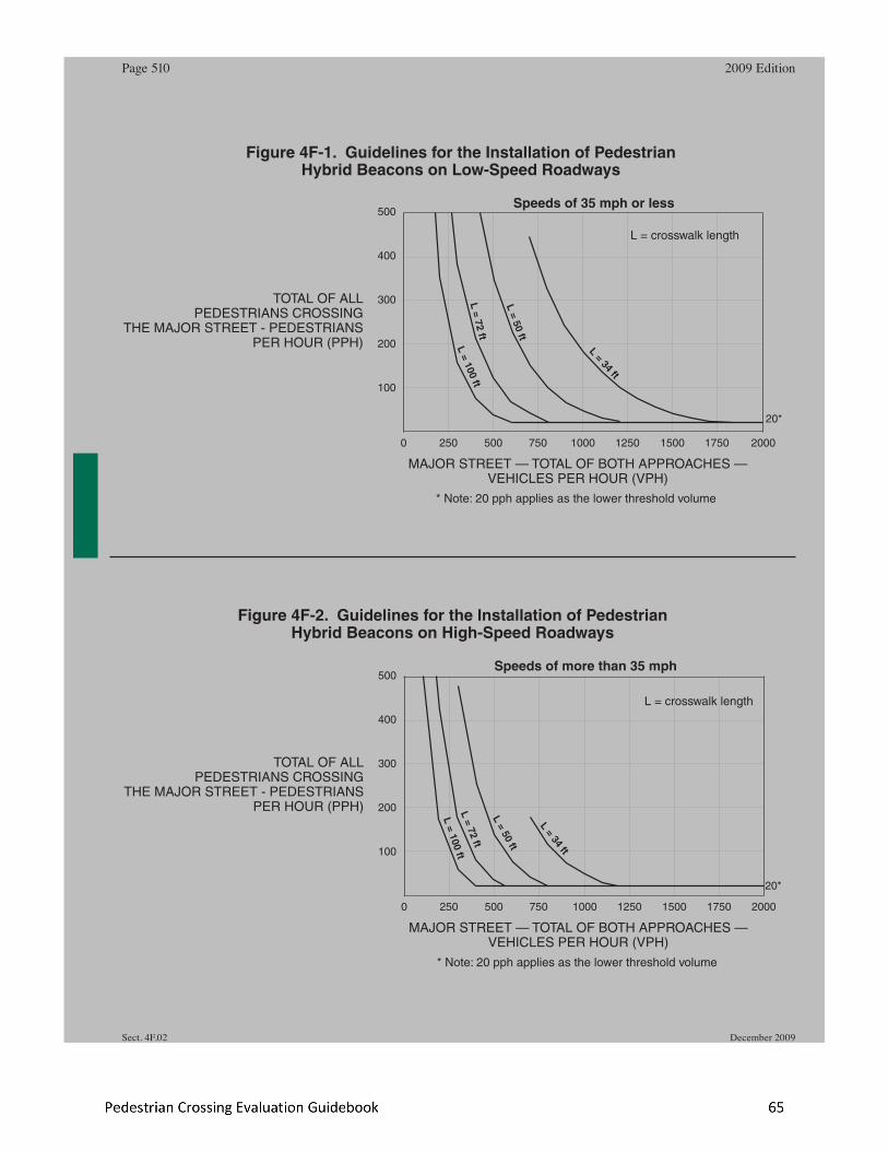
Page 510 2009 Edition
Figure 4F-1. Guidelines for the Installation of PedestrianHybrid Beacons on Low-Speed Roadways
MAJOR STREET — TOTAL OF BOTH APPROACHES —VEHICLES PER HOUR (VPH)
L = crosswalk length
0 250 750 1250 1750500 1000 1500 2000
100
200
300
400
500
TOTAL OF ALLPEDESTRIANS CROSSING
THE MAJOR STREET - PEDESTRIANSPER HOUR (PPH)
* Note: 20 pph applies as the lower threshold volume
L = 34 ft
L = 50 ft
L = 72 ft
L = 100 ft20*
Speeds of 35 mph or less
Figure 4F-2. Guidelines for the Installation of PedestrianHybrid Beacons on High-Speed Roadways
MAJOR STREET — TOTAL OF BOTH APPROACHES —VEHICLES PER HOUR (VPH)
0 500 1000 1500250 750 1250 1750 2000
100
200
300
400
500
TOTAL OF ALLPEDESTRIANS CROSSING
THE MAJOR STREET - PEDESTRIANSPER HOUR (PPH)
20*
L = crosswalk length
* Note: 20 pph applies as the lower threshold volume
L = 50 ft
L = 72 ft
L = 100 ft
L = 34 ft
Speeds of more than 35 mph
Sect. 4F.02 December 2009
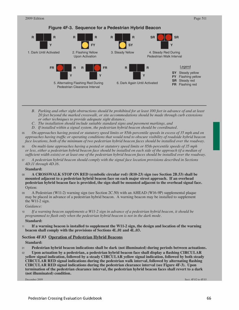
2009 Edition Page 511
B. Parking and other sight obstructions should be prohibited for at least 100 feet in advance of and at least 20 feet beyond the marked crosswalk, or site accommodations should be made through curb extensions or other techniques to provide adequate sight distance,
C. The installation should include suitable standard signs and pavement markings, and D. If installed within a signal system, the pedestrian hybrid beacon should be coordinated.
05 On approaches having posted or statutory speed limits or 85th-percentile speeds in excess of 35 mph and on approaches having traffic or operating conditions that would tend to obscure visibility of roadside hybrid beacon face locations, both of the minimum of two pedestrian hybrid beacon faces should be installed over the roadway.
06 On multi-lane approaches having a posted or statutory speed limits or 85th-percentile speeds of 35 mph or less, either a pedestrian hybrid beacon face should be installed on each side of the approach (if a median of sufficient width exists) or at least one of the pedestrian hybrid beacon faces should be installed over the roadway.
07 A pedestrian hybrid beacon should comply with the signal face location provisions described in Sections 4D.11 through 4D.16.Standard:
08 A CROSSWALK STOP ON RED (symbolic circular red) (R10-23) sign (see Section 2B.53) shall be mounted adjacent to a pedestrian hybrid beacon face on each major street approach. If an overhead pedestrian hybrid beacon face is provided, the sign shall be mounted adjacent to the overhead signal face.Option:
09 A Pedestrian (W11-2) warning sign (see Section 2C.50) with an AHEAD (W16-9P) supplemental plaque may be placed in advance of a pedestrian hybrid beacon. A warning beacon may be installed to supplement the W11-2 sign.Guidance:
10 If a warning beacon supplements a W11-2 sign in advance of a pedestrian hybrid beacon, it should be programmed to flash only when the pedestrian hybrid beacon is not in the dark mode.Standard:
11 If a warning beacon is installed to supplement the W11-2 sign, the design and location of the warning beacon shall comply with the provisions of Sections 4L.01 and 4L.03.
Section 4F.03 Operation of Pedestrian Hybrid BeaconsStandard:
01 Pedestrian hybrid beacon indications shall be dark (not illuminated) during periods between actuations.02 Upon actuation by a pedestrian, a pedestrian hybrid beacon face shall display a flashing CIRCULAR
yellow signal indication, followed by a steady CIRCULAR yellow signal indication, followed by both steady CIRCULAR RED signal indications during the pedestrian walk interval, followed by alternating flashing CIRCULAR RED signal indications during the pedestrian clearance interval (see Figure 4F-3). Upon termination of the pedestrian clearance interval, the pedestrian hybrid beacon faces shall revert to a dark (not illuminated) condition.
Figure 4F-3. Sequence for a Pedestrian Hybrid Beacon
RR
Y
1. Dark Until Activated
RR
FY
2. Flashing YellowUpon Activation
RR
SY
3. Steady Yellow
SRSR
Y
4. Steady Red DuringPedestrian Walk Interval
RR
Y
5. Alternating Flashing Red DuringPedestrian Clearance Interval
6. Dark Again Until Activated
RFR
Y
FRR
Y
Legend
SY Steady yellowFY Flashing yellowSR Steady redFR Flashing red
December 2009 Sect. 4F.02 to 4F.03
Page 512 2009 Edition
03 Except as provided in Paragraph 4, the pedestrian signal heads shall continue to display a steady UPRAISED HAND (symbolizing DONT WALK) signal indication when the pedestrian hybrid beacon faces are either dark or displaying flashing or steady CIRCULAR yellow signal indications. The pedestrian signal heads shall display a WALKING PERSON (symbolizing WALK) signal indication when the pedestrian hybrid beacon faces are displaying steady CIRCULAR RED signal indications. The pedestrian signal heads shall display a flashing UPRAISED HAND (symbolizing DONT WALK) signal indication when the pedestrian hybrid beacon faces are displaying alternating flashing CIRCULAR RED signal indications. Upon termination of the pedestrian clearance interval, the pedestrian signal heads shall revert to a steady UPRAISED HAND (symbolizing DONT WALK) signal indication.Option:
04 Where the pedestrian hybrid beacon is installed adjacent to a roundabout to facilitate crossings by pedestrians with visual disabilities and an engineering study determines that pedestrians without visual disabilities can be allowed to cross the roadway without actuating the pedestrian hybrid beacon, the pedestrian signal heads may be dark (not illuminated) when the pedestrian hybrid beacon faces are dark.Guidance:
05 The duration of the flashing yellow interval should be determined by engineering judgment.Standard:
06 The duration of the steady yellow change interval shall be determined using engineering practices.Guidance:
07 The steady yellow interval should have a minimum duration of 3 seconds and a maximum duration of 6 seconds (see Section 4D.26). The longer intervals should be reserved for use on approaches with higher speeds.
Sect. 4F.03 December 2009
North Carolina Pedestrian Crossing Guidance 68
Appendix C. TOTAL PEDESTRIAN DELAY CHARTS
This appendix provides a series of 15 quick-reference charts to assist evaluators in quickly estimating
Total Pedestrian Delay. These charts were prepared by utilizing two worksheets from NCHRP Report 562
to calculate Total Pedestrian Delay curves. The worksheets and list of variables and inputs that go into
them also are provided at the end of this appendix for situations in which an evaluator needs to
calculate Total Pedestrian Delay rather than rely on one of the quick-reference charts.
The quick-reference charts were developed using default assumptions and inputs for variables in the
worksheets. Charts are provided for two speed categories (less than or equal to 35 mph, or greater than
35 mph) and for locations where the area population is less than 10,000. Within each of these three
scenarios, one chart is provided for five different crossing distance assumptions: 12 ft., 24 ft., 36 ft., 48
ft., or 60 ft. Default values of 3.5 ft/sec for pedestrian walking speed and 3 sec for the pedestrian start-
up and end clearance times were used.
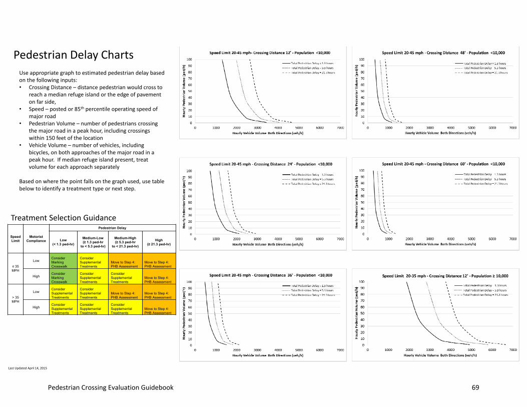
Pedestrian Delay Charts
Speed Limit
Motorist Compliance
Pedestrian Delay
Low (< 1.3 ped-hr)
Medium-Low(≥ 1.3 ped-hr
to < 5.3 ped-hr)
Medium-High(≥ 5.3 ped-hr
to < 21.3 ped-hr)
High(≥ 21.3 ped-hr)
≤ 35 MPH
LowConsider Marking Crosswalk
Consider Supplemental Treatments
Move to Step 4: PHB Assessment
Move to Step 4: PHB Assessment
HighConsider Marking Crosswalk
Consider Supplemental Treatments
Consider Supplemental Treatments
Move to Step 4: PHB Assessment
> 35 MPH
LowConsider Supplemental Treatments
Consider Supplemental Treatments
Move to Step 4: PHB Assessment
Move to Step 4: PHB Assessment
HighConsider Supplemental Treatments
Consider Supplemental Treatments
Consider Supplemental Treatments
Move to Step 4: PHB Assessment
Treatment Selection Guidance
Use appropriate graph to estimated pedestrian delay based on the following inputs:• Crossing Distance – distance pedestrian would cross to
reach a median refuge island or the edge of pavement on far side,
• Speed – posted or 85th percentile operating speed of major road
• Pedestrian Volume – number of pedestrians crossing the major road in a peak hour, including crossings within 150 feet of the location
• Vehicle Volume – number of vehicles, including bicycles, on both approaches of the major road in a peak hour. If median refuge island present, treat volume for each approach separately
Based on where the point falls on the graph used, use table below to identify a treatment type or next step.
Last Updated April 14, 2015
Pedestrian Crossing Evaluation Guidebook 69
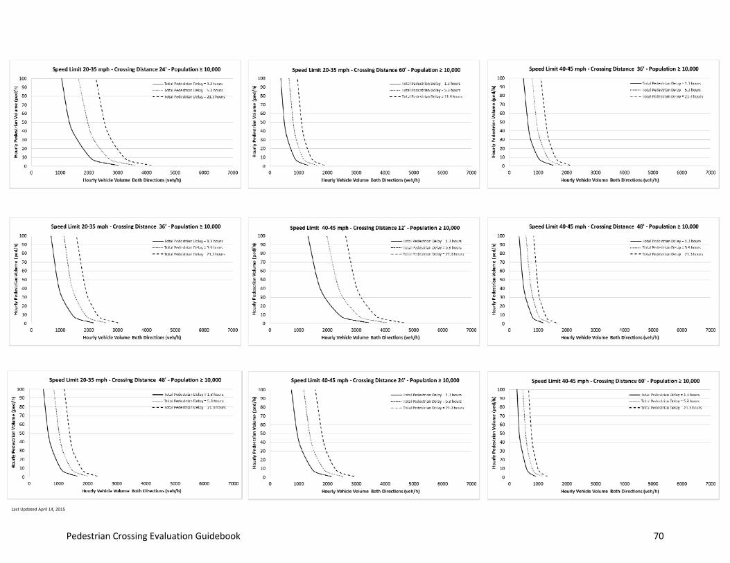
Last Updated April 14, 2015
Pedestrian Crossing Evaluation Guidebook 70
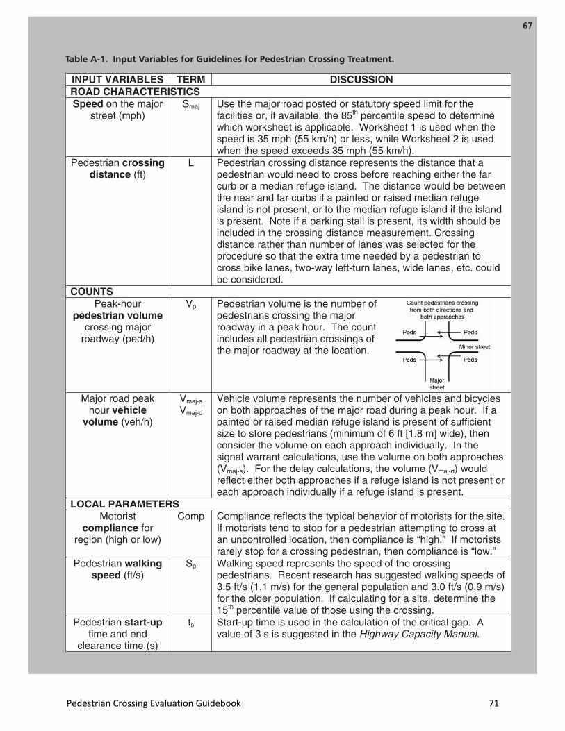
67
INPUT VARIABLES TERM DISCUSSION ROAD CHARACTERISTICS Speed on the major
street (mph) Smaj Use the major road posted or statutory speed limit for the
facilities or, if available, the 85th percentile speed to determine which worksheet is applicable. Worksheet 1 is used when the speed is 35 mph (55 km/h) or less, while Worksheet 2 is used when the speed exceeds 35 mph (55 km/h).
Pedestrian crossing distance (ft)
L Pedestrian crossing distance represents the distance that a pedestrian would need to cross before reaching either the far curb or a median refuge island. The distance would be between the near and far curbs if a painted or raised median refuge island is not present, or to the median refuge island if the island is present. Note if a parking stall is present, its width should be included in the crossing distance measurement. Crossing distance rather than number of lanes was selected for the procedure so that the extra time needed by a pedestrian to cross bike lanes, two-way left-turn lanes, wide lanes, etc. could be considered.
COUNTS Peak-hour
pedestrian volume crossing major
roadway (ped/h)
Vp Pedestrian volume is the number of pedestrians crossing the major roadway in a peak hour. The count includes all pedestrian crossings of the major roadway at the location.
Major road peak hour vehicle
volume (veh/h)
Vmaj-s
Vmaj-d Vehicle volume represents the number of vehicles and bicycles on both approaches of the major road during a peak hour. If a painted or raised median refuge island is present of sufficient size to store pedestrians (minimum of 6 ft [1.8 m] wide), then consider the volume on each approach individually. In the signal warrant calculations, use the volume on both approaches (Vmaj-s). For the delay calculations, the volume (Vmaj-d) would reflect either both approaches if a refuge island is not present or each approach individually if a refuge island is present.
LOCAL PARAMETERS Motorist
compliance for region (high or low)
Comp Compliance reflects the typical behavior of motorists for the site. If motorists tend to stop for a pedestrian attempting to cross at an uncontrolled location, then compliance is “high.” If motorists rarely stop for a crossing pedestrian, then compliance is “low.”
Pedestrian walking speed (ft/s)
Sp Walking speed represents the speed of the crossing pedestrians. Recent research has suggested walking speeds of 3.5 ft/s (1.1 m/s) for the general population and 3.0 ft/s (0.9 m/s) for the older population. If calculating for a site, determine the 15th percentile value of those using the crossing.
Pedestrian start-up time and end
clearance time (s)
ts Start-up time is used in the calculation of the critical gap. A value of 3 s is suggested in the Highway Capacity Manual.
Table A-1. Input Variables for Guidelines for Pedestrian Crossing Treatment.
Pedestrian Crossing Evaluation Guidebook 71
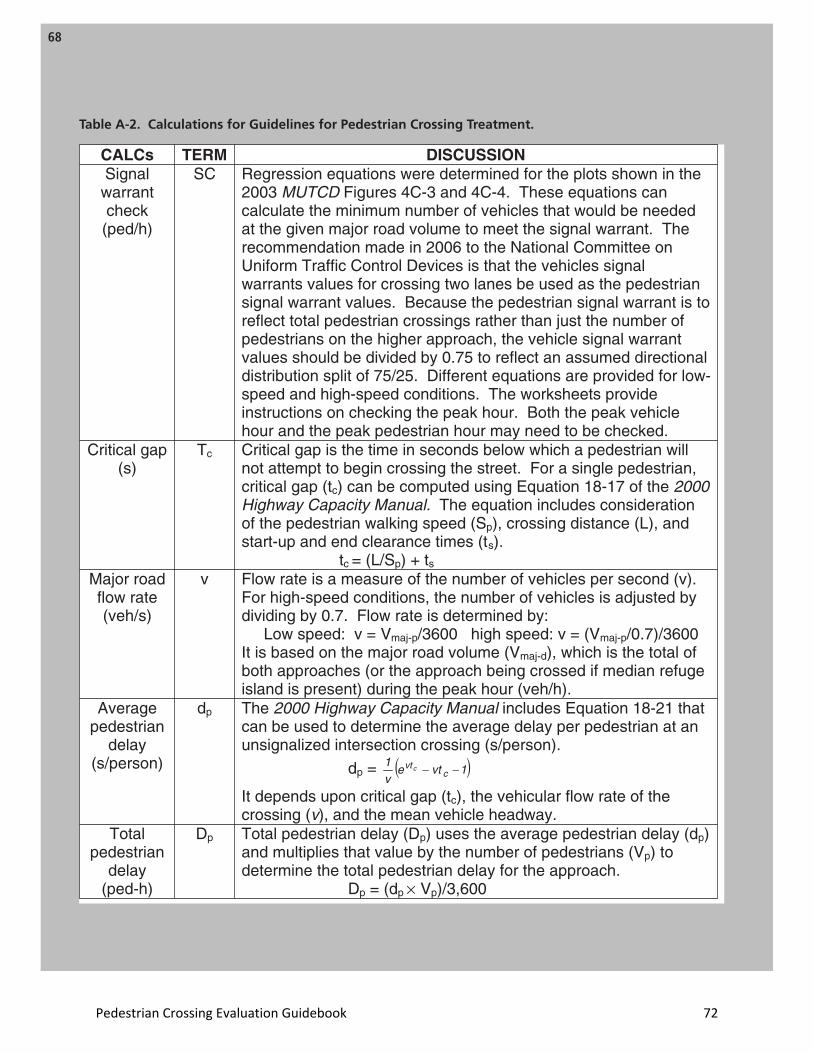
68
CALCs TERM DISCUSSION Signal
warrant check
(ped/h)
SC Regression equations were determined for the plots shown in the 2003 MUTCD Figures 4C-3 and 4C-4. These equations can calculate the minimum number of vehicles that would be needed at the given major road volume to meet the signal warrant. The recommendation made in 2006 to the National Committee on Uniform Traffic Control Devices is that the vehicles signal warrants values for crossing two lanes be used as the pedestrian signal warrant values. Because the pedestrian signal warrant is to reflect total pedestrian crossings rather than just the number of pedestrians on the higher approach, the vehicle signal warrant values should be divided by 0.75 to reflect an assumed directional distribution split of 75/25. Different equations are provided for low-speed and high-speed conditions. The worksheets provide instructions on checking the peak hour. Both the peak vehicle hour and the peak pedestrian hour may need to be checked.
Critical gap (s)
Tc Critical gap is the time in seconds below which a pedestrian will not attempt to begin crossing the street. For a single pedestrian, critical gap (tc) can be computed using Equation 18-17 of the 2000 Highway Capacity Manual. The equation includes consideration of the pedestrian walking speed (Sp), crossing distance (L), and start-up and end clearance times (ts). tc = (L/Sp) + ts
Major road flow rate (veh/s)
v Flow rate is a measure of the number of vehicles per second (v). For high-speed conditions, the number of vehicles is adjusted by dividing by 0.7. Flow rate is determined by: Low speed: v = Vmaj-p/3600 high speed: v = (Vmaj-p/0.7)/3600 It is based on the major road volume (Vmaj-d), which is the total of both approaches (or the approach being crossed if median refuge island is present) during the peak hour (veh/h).
Average pedestrian
delay (s/person)
dp The 2000 Highway Capacity Manual includes Equation 18-21 that can be used to determine the average delay per pedestrian at an unsignalized intersection crossing (s/person).
dp = ( )1vtev1
cvt c − −
It depends upon critical gap (tc), the vehicular flow rate of the crossing (v), and the mean vehicle headway.
Total pedestrian
delay (ped-h)
Dp Total pedestrian delay (Dp) uses the average pedestrian delay (dp) and multiplies that value by the number of pedestrians (Vp) to determine the total pedestrian delay for the approach. Dp = (dp × Vp)/3,600
Table A-2. Calculations for Guidelines for Pedestrian Crossing Treatment.
Pedestrian Crossing Evaluation Guidebook 72
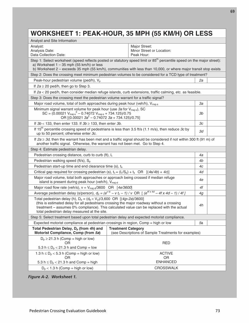
69
WORKSHEET 1: PEAK-HOUR, 35 MPH (55 KM/H) OR LESS Analyst and Site Information
Analyst: Analysis Date: Data Collection Date:
Major Street: Minor Street or Location: Peak Hour:
Step 1: Select worksheet (speed reflects posted or statutory speed limit or 85th percentile speed on the major street): a) Worksheet 1 – 35 mph (55 km/h) or less
b) Worksheet 2 – exceeds 35 mph (55 km/h), communities with less than 10,000, or where major transit stop exists
Step 2: Does the crossing meet minimum pedestrian volumes to be considered for a TCD type of treatment?
Peak-hour pedestrian volume (ped/h), Vp 2a
If 2a ≥ 20 ped/h, then go to Step 3.
If 2a < 20 ped/h, then consider median refuge islands, curb extensions, traffic calming, etc. as feasible.
Step 3: Does the crossing meet the pedestrian volume warrant for a traffic signal?
Major road volume, total of both approaches during peak hour (veh/h), Vmaj-s 3a
Minimum signal warrant volume for peak hour (use 3a for Vmaj-s), SC SC = (0.00021 Vmaj-s
2 – 0.74072 Vmaj-s + 734.125)/0.75 OR [(0.00021 3a2 – 0.74072 3a + 734.125)/0.75]
3b
If 3b < 133, then enter 133. If 3b ≥ 133, then enter 3b. 3c
If 15th percentile crossing speed of pedestrians is less than 3.5 ft/s (1.1 m/s), then reduce 3c by up to 50 percent; otherwise enter 3c. 3d
If 2a ≥ 3d, then the warrant has been met and a traffic signal should be considered if not within 300 ft (91 m) of another traffic signal. Otherwise, the warrant has not been met. Go to Step 4.
Step 4: Estimate pedestrian delay.
Pedestrian crossing distance, curb to curb (ft), L 4a
Pedestrian walking speed (ft/s), Sp 4b
Pedestrian start-up time and end clearance time (s), ts 4c
Critical gap required for crossing pedestrian (s), tc = (L/Sp) + ts OR [(4a/4b) + 4c)] 4d
Major road volume, total both approaches or approach being crossed if median refuge island is present during peak hour (veh/h), Vmaj-d
4e
Major road flow rate (veh/s), v = Vmaj-d/3600 OR [4e/3600] 4f
Average pedestrian delay (s/person), dp = (ev tc – v tc – 1) / v OR [ (e4f x 4d – 4f x 4d – 1) / 4f ] 4g
Total pedestrian delay (h), Dp = (dp × Vp)/3,600 OR [(4g×2a)/3600] (this is estimated delay for all pedestrians crossing the major roadway without a crossing
treatment – assumes 0% compliance). This calculated value can be replaced with the actual total pedestrian delay measured at the site.
4h
Step 5: Select treatment based upon total pedestrian delay and expected motorist compliance.
Expected motorist compliance at pedestrian crossings in region, Comp = high or low 5a
Total Pedestrian Delay, Dp (from 4h) and Motorist Compliance, Comp (from 5a)
Treatment Category (see Descriptions of Sample Treatments for examples)
Dp ≥ 21.3 h (Comp = high or low) OR
5.3 h ≤ Dp < 21.3 h and Comp = low RED
1.3 h ≤ Dp < 5.3 h (Comp = high or low) OR
5.3 h ≤ Dp < 21.3 h and Comp = high
ACTIVE OR
ENHANCED
Dp < 1.3 h (Comp = high or low) CROSSWALK
Figure A-2. Worksheet 1.
Pedestrian Crossing Evaluation Guidebook 73
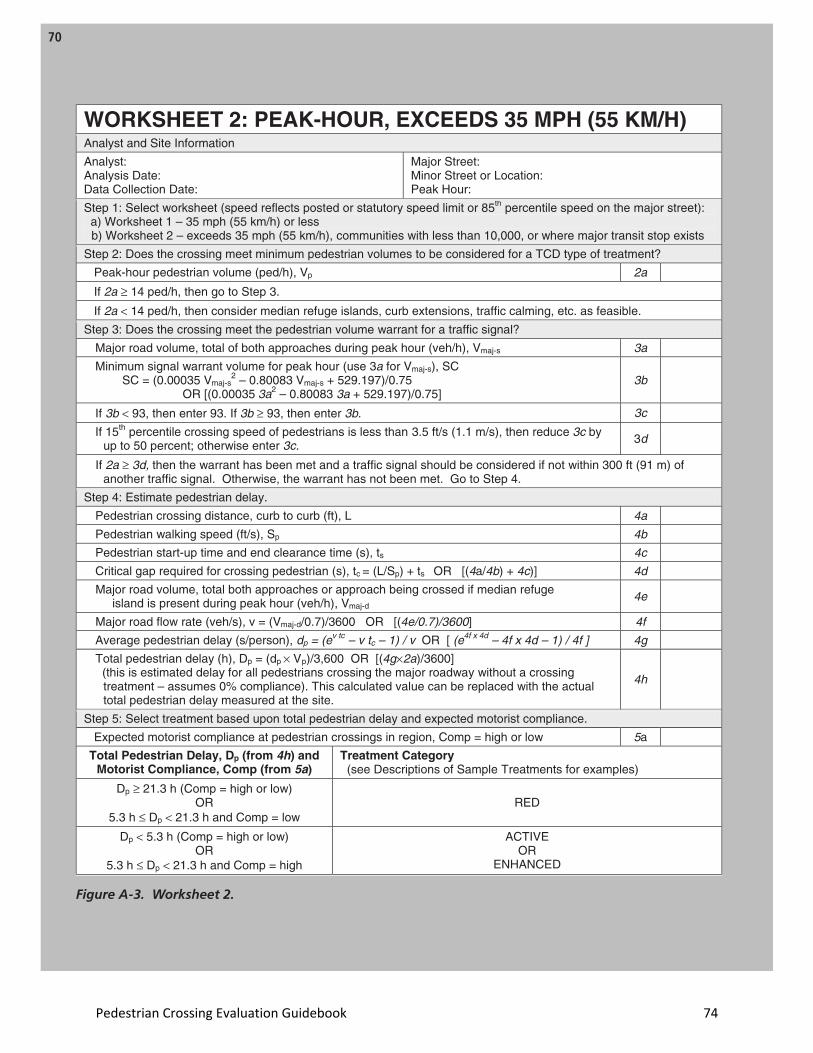
70
WORKSHEET 2: PEAK-HOUR, EXCEEDS 35 MPH (55 KM/H) Analyst and Site Information
Analyst: Analysis Date: Data Collection Date:
Major Street: Minor Street or Location: Peak Hour:
Step 1: Select worksheet (speed reflects posted or statutory speed limit or 85th percentile speed on the major street): a) Worksheet 1 – 35 mph (55 km/h) or less
b) Worksheet 2 – exceeds 35 mph (55 km/h), communities with less than 10,000, or where major transit stop exists
Step 2: Does the crossing meet minimum pedestrian volumes to be considered for a TCD type of treatment?
Peak-hour pedestrian volume (ped/h), Vp 2a
If 2a ≥ 14 ped/h, then go to Step 3.
If 2a < 14 ped/h, then consider median refuge islands, curb extensions, traffic calming, etc. as feasible.
Step 3: Does the crossing meet the pedestrian volume warrant for a traffic signal?
Major road volume, total of both approaches during peak hour (veh/h), Vmaj-s 3a
Minimum signal warrant volume for peak hour (use 3a for Vmaj-s), SC SC = (0.00035 Vmaj-s
2 – 0.80083 Vmaj-s + 529.197)/0.75 OR [(0.00035 3a2 – 0.80083 3a + 529.197)/0.75]
3b
If 3b < 93, then enter 93. If 3b ≥ 93, then enter 3b. 3c
If 15th percentile crossing speed of pedestrians is less than 3.5 ft/s (1.1 m/s), then reduce 3c by up to 50 percent; otherwise enter 3c. 3d
If 2a ≥ 3d, then the warrant has been met and a traffic signal should be considered if not within 300 ft (91 m) of another traffic signal. Otherwise, the warrant has not been met. Go to Step 4.
Step 4: Estimate pedestrian delay.
Pedestrian crossing distance, curb to curb (ft), L 4a
Pedestrian walking speed (ft/s), Sp 4b
Pedestrian start-up time and end clearance time (s), ts 4c
Critical gap required for crossing pedestrian (s), tc = (L/Sp) + ts OR [(4a/4b) + 4c)] 4d
Major road volume, total both approaches or approach being crossed if median refuge island is present during peak hour (veh/h), Vmaj-d
4e
Major road flow rate (veh/s), v = (Vmaj-d/0.7)/3600 OR [(4e/0.7)/3600] 4f
Average pedestrian delay (s/person), dp = (ev tc – v tc – 1) / v OR [ (e4f x 4d – 4f x 4d – 1) / 4f ] 4g
Total pedestrian delay (h), Dp = (dp × Vp)/3,600 OR [(4g×2a)/3600] (this is estimated delay for all pedestrians crossing the major roadway without a crossing
treatment – assumes 0% compliance). This calculated value can be replaced with the actual total pedestrian delay measured at the site.
4h
Step 5: Select treatment based upon total pedestrian delay and expected motorist compliance.
Expected motorist compliance at pedestrian crossings in region, Comp = high or low 5a
Total Pedestrian Delay, Dp (from 4h) and Motorist Compliance, Comp (from 5a)
Treatment Category (see Descriptions of Sample Treatments for examples)
Dp ≥ 21.3 h (Comp = high or low) OR
5.3 h ≤ Dp < 21.3 h and Comp = low RED
Dp < 5.3 h (Comp = high or low) OR
5.3 h ≤ Dp < 21.3 h and Comp = high
ACTIVE OR
ENHANCED
Figure A-3. Worksheet 2.
Pedestrian Crossing Evaluation Guidebook 74
North Carolina Pedestrian Crossing Guidance 75
Appendix D. LITERATURE REVIEW AND STATE OF THE PRACTICE
Guidance for the application of pedestrian signal heads is principally provided in section 4E.03 of the
2009 Manual of Uniform Traffic Control Devices (MUTCD) (2009). The premise of the MUTCD guidance is
to consider the use of pedestrian signal heads at locations where pedestrian volumes warrant them,
where special populations may be present (i.e. a school crossing), or where vehicular signal indications
provide insufficient guidance for pedestrians to safely decide when to cross, such as where signal
phasing may confuse or cause conflicts with pedestrians or where they may have limited visibility of the
signals. The MUTCD also provides general guidance and support about crosswalk markings. However,
the MUTCD does not describe conditions under which a crosswalk must be marked, nor does it provide
conditions under which the installation of a traffic signal or pedestrian hybrid beacon is required.
In research, Fitzpatrick et al. (Fitzpatrick, et al., TCRP Report 112/NCHRP Report 562: Improving
Pedestrian Safety at Unsignalized Intersections, 2006) performed a comprehensive review of pedestrian
and vehicle interaction at unsignalized intersections, which included a thorough review of various
pedestrian crossing treatments. That research is also the basis of the revised pedestrian volume traffic
signal warrant (Warrant 4) in the 2009 MUTCD.
Even before the discussion of specific crossing treatments, the decision of whether or not to mark a
crosswalk is an important consideration. In research performed by Zegeer et al. (Zegeer, et al., Safety
Effects of Marked Versus Unmarked Crosswalks at Uncontrolled Locations, 2005) the authors quantified
the safety performance of marked and unmarked crosswalks at uncontrolled locations, and they
concluded that striping of crosswalks alone may in some cases actually have a negative impact on
pedestrian safety. The research resulted in a table of guidelines for marking uncontrolled crosswalk
locations as a function of crossing widths and vehicular traffic demands, which is reflected in the revised
crosswalk marking guidance (section 3B.18.09) in the 2009 MUTCD.
In an effort to overcome some of the limitations of the MUTCD, several states and municipalities have
developed their own guidance for the provision of pedestrian signals and other crossing treatments.
Examples of this practice include the Pedestrian Guide or Signal Guidelines for states like Minnesota
(2005), Alabama (Alabama Department of Transportation, 2007), California (California Department of
Transportation, 2012), and Georgia (Georgia Department of Transportation, 2011), as well as municipal
guidance including special pedestrian warrants for the City of Boulder, Colorado (City of Boulder
Department of Transportation, 2011), or the Pedestrian Safety Guidelines for Sacramento, CA
(Sacramento Transportation & Air Quality Collaborative, 2005). Even so, according to the Uncontrolled
Crossings Task Force who conducted a survey of current practices in 2013, two-thirds of the jurisdictions
who responded do not have written policies or guidelines other than the MUTCD for applying marked
crosswalks. The majority of the agency respondents indicated the need for improved guidance for the
installation of pedestrian crossing treatments, specifically on when to install a crosswalk and what
treatment to apply. (Uncontrolled Crossings Task Force, 2014)
In general, the NCDOT relies on the MUTCD for guidance on crossing treatments and does not have
additional written policies or guidelines. The NCDOT issued a policy of standard practice criteria and
recommendations in February 2008 for marking and signing mid-block crosswalks specifically. The
policy calls for an engineering study to be conducted to determine that a mid-block crosswalk would
North Carolina Pedestrian Crossing Guidance 76
improve operation and pedestrian safety in lieu of other traffic control measures, but it does not identify
factors or locations where mid-block crosswalks should be considered. It does, however, provide
guidance on where they should not be installed with considerations for speed, proximity to adjacent
crossing locations, visibility, and traffic volume for both pedestrians and vehicles; and how they may be
enhanced through the installation of refuge islands, in-street signage, high visibility markings and other
treatments. (North Carolina Department of Transportation, 2008)
The2009 MUTCD currently allows for many different styles of crosswalk markings including high visibility
markings with longitudinal lines parallel to traffic flow. Little guidance is given on when to use a
particular style of marking, which allows for agency flexibility; however, the National Committee on
Uniform Traffic Control Devices (NCUTCD) issued a recommendation in 2011 to modify the MUTCD to
clarify specification details when using high visibility markings. (Markings Technical Committee of the
NCUTCD, 2011) This recommendation incorporates findings from research done by Fitzpatrick et al. on
the daytime and nighttime visibility of different marking styles. (Fitzpatrick K. , Chrysler, Iragavarapu, &
Park, November 2010) While the research determined high visibility markings were more easily
detected further upstream compared with continental markings, no research was found that
investigated whether yielding rates are impacted by different crosswalk marking styles.
In the consideration of pedestrian performance at signalized and unsignalized crossings, methodologies
in the Highway Capacity Manual (Transportation Research Board, 2010) may be used to predict
pedestrian delay at signalized intersections, with additional detail for unsignalized intersection theory
given in Troutbeck and Brilon (Troutbeck & Brilon, 2002). Another valuable source for pedestrian
treatments and countermeasures is PEDSAFE (Federal Highway Administration, 2013), which contains a
variety of case studies on pedestrian treatment applications and describes 11 countermeasures specific
to crossing locations. Guidance on pedestrian accommodations and performance at modern
roundabouts is available in Rodegerdts et al. (Rodegerdts & et al., 2007), and while roundabouts are not
the central piece of this research, lessons learned from the report can be applied to other unsignalized
applications.
A key consideration in pedestrian accommodations is the special needs and civil rights of pedestrians
with disabilities. To that effect, the US Access Board (US Access Board, 2006) has issued draft Guidelines
for Accessible Public Rights of Way (PROWAG), which includes specific requirements for public rights of
way that are expected to be adopted by the U.S. Department of Justice in the near future. The PROWAG
references several countermeasures specific for pedestrians, many of which have been evaluated in
recent work for the Federal Highway Administration (Fitzpatrick K. , Chrysler, Houten, Hunter, & Turner,
2011) (Fitzpatrick & Park, 2010). Additionally, a technical assistance memo jointly issued by the
Department of Justice and the Department of Transportation to clarify curb ramp requirements states
that “crosswalks constitute distinct elements of the right-of-way intended for pedestrian traffic.”
(Department of Justice/Department of Transportation, July 8, 2013)
The review of the literature speaks to the complexity of the decision-making process for selecting
pedestrian treatments, and specifically for the provision of pedestrian signals and marked crosswalks at
intersections and midblock locations. This complexity clearly speaks to the need for this research, which
will result in clear guidelines for application in North Carolina.
North Carolina Pedestrian Crossing Guidance 77
D.1 STATE OF THE PRACTICE The researchers surveyed multiple agencies throughout North Carolina including the state highway
divisions and the larger municipalities across the state. These agencies discussed the current practice
and/or guidelines being followed for when to implement a crosswalk or other pedestrian crossing
treatment in their division or municipality. Agencies outside of North Carolina were also contacted.
D.2 NORTH CAROLINA HIGHWAY DIVISIONS All 14 of the North Carolina highway divisions were contacted about the current practices in their
division regarding marking crosswalks and implementing additional pedestrian facilities. In most cases
the division traffic engineer spoke on behalf of the division. All were initially asked some basic questions
about how many requests are received each year for a pedestrian facility and how these requests are
brought to the attention of the division traffic engineer. On average, each division receives around 10 to
15 requests from citizens or municipalities.
After a request is received, a site visit is conducted. Three main considerations are noted at the site:
presence of an existing sidewalk network, pedestrian volumes, and site geometry:
Most divisions said that if a sidewalk network was present, including curb ramps, then the
crosswalk marking would most likely be approved. However, if the sidewalk network was not
present, or if present but no curb ramps, then the crosswalk marking would either be denied or
the division would propose a joint project with the municipality. If the municipality agreed to
construct the sidewalks and/or construct the curb ramps, then the division would agree to mark
the crosswalk.
Pedestrian volume was recorded to justify a pedestrian signal or other pedestrian crossing
treatment based on the MUTCD warrants. However, at the time they were interviewed, some
divisions felt that the MUTCD warrants were too high and developed their own threshold of 20-
30 pedestrian crossings per hour. Additionally, at locations where requests are simply to mark a
crosswalk, the site was observed for pedestrian activity, and no specific counts were taken.
Other site characteristics were considered, including width of the roadway, speed limit (85th
percentile), site distance, proximity to a school or greenway, and if the location was for a
crosswalk at an intersection or midblock. Marking crosswalks at intersections were more
straightforward to approve than at midblock locations. Other considerations that were
mentioned included crash history, vehicle volumes, constructability and cost.
The MUTCD was most often cited by NCDOT division staff for pedestrian warrants, but half of the
divisions also mentioned Traffic Engineering Policies, Practices, and Legal Authority (TEPPL) Topic C-36
(North Carolina Department of Transportation, 2008) as the source used when considering mid-block
crosswalks. Additionally, Division 3 has developed their own guidance for marking crosswalks in beach
communities (NCDOT Division 3, December 21, 2010). This guideline considers beach access points,
number of residential units, crash history, pedestrian population (i.e. handicapped or senior citizens)
and the local adopted pedestrian plan.
High visibility crosswalks were mentioned by most of the divisions, though the use of high visibility
crosswalks was varied. Some thought that high visibility crosswalks should only be place at midblock
North Carolina Pedestrian Crossing Guidance 78
locations or at locations were pedestrians were unlikely to be, while others thought that high visibility
should be applied to all crosswalks.
The divisions were asked to discuss what other crossing treatments beyond marked crosswalks are
considered and the decision process(es) through which they are implemented. Pedestrian signals were
mentioned as an additional treatment with most divisions using the MUTCD warrants as justification
while others considered lower pedestrian volumes than the MUTCD. One division noted that it was
unclear when to install a pedestrian signal based on the new complete street guidelines. Four divisions
have used pedestrian hybrid beacons (PHB) and three have used rectangular rapid-flash beacons (RRFB)
to enhance specific crossing locations.
Overall, the divisions seemed pleased that additional guidance through this research would soon be
developed to aid in the decision-making process. Some requested more specific guidance for when to
implement PHBs and RRFBs. Others mentioned that they preferred the guidelines be flexible so as not
to rule out engineering judgment.
D.3 LARGE NORTH CAROLINA MUNICIPALITIES Nine major municipalities within North Carolina gave information about how marked crosswalks are
implemented within their cities, including: Asheville, Cary, Charlotte, Durham, Fayetteville, Greensboro,
Raleigh, Wilmington, and Winston-Salem. Either a city transportation engineer or the city traffic
engineer represented the city during the interview. The amount of requests that are received by each of
these cities varies greatly, with some cities only receiving a few, while others receive hundreds a year.
Each of the cities conducts a site visit upon receiving a request for a pedestrian treatment. The major
considerations that are noted while on site include the pedestrian volume and site characteristics. In
most cases, the site is observed for pedestrian activity - counts are conducted when a pedestrian signal
is being considered or for midblock locations. Site characteristics include nearby pedestrian generators
(i.e. schools, proximity to city trails), crossing distances or number of lanes, landscape, grading, roadway
alignment, street lighting, and presence of a refuge island and if the location will be a midblock or an
intersection crosswalk. Another consideration mentioned by half the cities is the presence of an existing
sidewalk and curb ramps. In most cases the city will try to install or update curb ramps, if needed, but
this effort may be limited by available funds. Some cities are being proactive and are working to fill in
gaps in the existing sidewalk network and mark crosswalks to extend the network. Furthermore, some
cities are also being proactive with new construction projects by setting the stop bar and loop detectors
back in anticipation of marking the crosswalk location when future need arises.
The cities referenced the MUTCD for signal warrants but also considered a multitude of other resources
published from ITE, FHWA, and AASHTO, as well as the NCDOT Complete Street Planning and Design
Guidelines. Some cities (Cary, Charlotte, Raleigh, and Wilmington) have developed their own set of
guidelines for when to mark a crosswalk, specifically at unsignalized locations.
Similar to the additional pedestrian treatments mentioned by the highway divisions, a popular
treatment for municipalities is the high visibility crosswalk. The application of these markings included
crossings at or near: greenways, schools, midblock locations, high pedestrian crossing locations, and
busy streets. More than half of the cities discussed providing midblock crossing locations as an
additional pedestrian treatment, implemented at greenways and locations with high volumes of
North Carolina Pedestrian Crossing Guidance 79
pedestrians. Three cities have installed PHBs and three have installed RRFBs. Additional treatments
mentioned included refuge islands, pedestrian warning signs, stamped crosswalks, striping an edge line
to create a multi-use lane, flexible delineator posts, and camera detection of bicyclists and/or
pedestrians at trail crossings.
At the end of the interview, the city representatives were asked for any additional comments they
would like to add, and a great amount of feedback was collected.
One city would like to use the In-Street Pedestrian Crossing sign (R1-6) in more locations but felt
that they were restricted on the acceptable locations.
Current NCDOT practices suggest that the state treats policy much of the “should” and “may”
guidance in the MUTCD as “shall”, while municipalities tend to make use of the flexibility written
in the MUTCD.
One city suggested that a crossing difficulty index be included with the crosswalk guidance. The
index would add weight or emphasis to special needs populations and specific origins-
destinations. One example would be that a difficult crossing with a low volume of pedestrians
would have a similar weight or emphasis as an easy crossing with a high volume of pedestrians.
Another city solicits requests each year from the citizens and staff on locations that need
improvement. This city works to fill in the gaps of the sidewalk network and construct as many
crosswalks as allowed by the annual budget.
In other areas, developers may be asked to provide pedestrian treatments if a new development
is predicted to generate pedestrian volumes.
Overall the cities seemed to approve a majority of the crosswalk requests, within the limits of a specific
budget. Many are trying to be proactive with pedestrian facilities and are working to promote walking.
Additionally, the cities are eager to see the completed guidance, particularly information on PHBs and
RRFBs.
D.4 OTHER STATES To date, two agencies outside of North Carolina have been contacted about their current crosswalk
guidelines; Minnesota DOT (MnDOT) and the city of Boulder, CO.
D.4.1 Minnesota Department of Transportation A pedestrian and bicycle safety engineer for MnDOT discussed the current state crosswalk guidance
being implemented. The Guidance for Installation of Pedestrian Crosswalks in Minnesota was first
released in 2005 and is currently undergoing an update. The existing guidance includes a report and a
flowchart, which is loosely based on the 2002 FHWA executive summary and recommended guidelines
of the Safety Effects of Marked vs. Unmarked Crosswalks at Uncontrolled Locations (Zegeer, Stewart,
Huang, & Lagerwey, Safety Effects of Marked Vs. Unmarked Crosswalks at Uncontrolled Locations:
Executive Summary and Recommended Guidelines, 2002). The Minnesota guidance has received mixed
reviews; the pedestrian and bicycling community feels that it is too restrictive with too strong of
wording, while city engineers tend to mark crosswalks more often than the guide would suggest, and
the state engineers are content with the current guide. The new guideline being developed will
implement changes based on the various feedback and criticisms MnDOT has received since the original
guideline was released. These include the following:

North Carolina Pedestrian Crossing Guidance 80
Addition of a table similar to the one in the 2002 FHWA study (Zegeer, Stewart, Huang, &
Lagerwey, Safety Effects of Marked Vs. Unmarked Crosswalks at Uncontrolled Locations:
Executive Summary and Recommended Guidelines, 2002)
Work to include more of the guidance from the 2002 FHWA study (Zegeer, Stewart, Huang, &
Lagerwey, Safety Effects of Marked Vs. Unmarked Crosswalks at Uncontrolled Locations:
Executive Summary and Recommended Guidelines, 2002)
Information on when to consider additional crossing treatments, like how the city of Boulder
does for RRFBs
Incorporate some of the information currently found only in the report into the flow chart as
well
Add information on additional countermeasures to improve safety, such as, curb extensions at
crosswalk locations, intersection and street lighting, and address the multiple-threat scenario
by, for example, using overhead RRFBs
MnDOT found that the report section of the original guide was being overlooked and that most
engineers using the guide would view only the flow chart. Furthermore, the state often fields
complaints from citizens about lack of consistency in its application across the state. The original guide
was meant to standardize practice, but since the guideline is not mandated, inconsistencies remain.
One additional point that was made is that the state is currently conducting research into automated
pedestrian and bicycle counts which will aid in the state being more proactive with pedestrian
treatments and crossing facilities in the future.
D.4.2 City of Boulder, Colorado A transportation operations engineer from the city of Boulder, CO was contacted to discuss the current
crosswalk guideline being implemented by the city. The Pedestrian Crossing Treatment Installation
Guidelines was created in 1996 and has since undergone three revisions, with the latest update in 2011.
The first version was found to be insufficient and relied heavily on engineering judgment. The current
revision had the following updates:
Added guidance on new crossing treatments including RRFBs
Examined how to improve compliance
Provided research sources to back up data
The current guide is typically used for low volume roads and to determine minimum pedestrian volume
thresholds. Additionally, the latest version has received positive response from the bicycling and
pedestrian community.
The current guideline contains a flow chart with thresholds originating from the 2005 FHWA study
(Zegeer, et al., Safety Effects of Marked Versus Unmarked Crosswalks at Uncontrolled Locations, 2005)
and have been verified by city engineers. The city also examined the effect of pedestrian volume on
vehicle compliance, and found that 15-20 crossings per hour resulted in good compliance.
One of the new crossing treatments that was included in the guideline is the RRFB; on which the city has
done extensive research from their own installations and from gathering information from other parts
of the country. The first RRFB was installed 15 years ago. Since then, 20 different locations have been
evaluated, with several of the locations eventually replaced with a traffic signal. Outside of the state,

North Carolina Pedestrian Crossing Guidance 81
the city has gathered information from Oregon where RRFBs are installed in rural locations with high
speeds.
Besides RRFBs, the city has also implemented PHBs but has found these devices to not be very
successful. Compliance did not improve with the installation of a PHB and produced similar results as a
traffic signal. When deciding whether to install a PHB or a signal, the city prefers to install a traffic
signal.
D.5 APPENDIX REFERENCES AASHTO. (2012). Guide for the Development of Bicycle Facilities (4th Edition ed.). Washington, DC:
American Association of State Highway and Transportation Officials.
Alabama Department of Transportation. (2007). Traffic Signal Design Guide & Timing Manual. Alabama
Department of Transportation.
California Department of Transportation. (2012). California Manual on Uniform Traffic Control Devices.
California Department of Transportation.
City of Boulder Department of Transportation. (2011). Pedestrian Crossing Treatment Installation
Guidelines. Boulder, CO: City of Boulder Transportation Division.
DOJ/DOT. (2013, July 8). Department of Justice/Department of Transporation Joint Technical Assistance
on the Title II of the Americans with Disabilities Act Requirements to Provide Curb Ramps when
Streets, Roads, or Highways are Altered through Resurfacing. Retrieved March 23, 2015, from
ADA.gov: http://www.ada.gov/doj-fhwa-ta.htm
Federal Highway Administration. (2009). Manual on Uniform Traffic Control Devices for Streets and
Highways (MUTCD). Retrieved December 9, 2014, from USDOT - FHWA:
http://mutcd.fhwa.dot.gov/htm/2009r1r2/html_index.htm
Federal Highway Administration. (2013, August). Pedestrian Safety Guide and Countermeasure Selection
System. (USDOT-FHWA) Retrieved December 9, 2014, from PEDSAFE:
http://www.pedbikesafe.org/PEDSAFE/
Fitzpatrick, K., & Park, E. (2010). Safety Effectiveness of the HAWK Pedestrian Crossing Treatment.
Washington, D.C.: Federal Highway Administration.
Fitzpatrick, K., Chrysler, S. T., Houten, R. V., Hunter, W., & Turner, S. (2011). Evaluation of Pedestrian and
Bicycle Engineering Countermeasures: Rectangular Rapid-Flashing Beacons, HAWKs, Sharrows,
Crosswalk Markings, and the Development of an Evaluation Methods Report. Washington, D.C.:
Federal Highway Administration.
Fitzpatrick, K., Chrysler, S. T., Iragavarapu, V., & Park, E. S. (November 2010). Crosswalk Marking Field
Visibility Study. Alexandria: Federal Highway Administration.
Fitzpatrick, K., Turner, S., Brewer, M., Carlson, P., Ullman, B., Trout, N., . . . Lord, D. (2006). TCRP Report
112/NCHRP Report 562: Improving Pedestrian Safety at Unsignalized Intersections. Retrieved
December 9, 2014, from Transportation Research Board:
http://onlinepubs.trb.org/onlinepubs/nchrp/nchrp_rpt_562.pdf
North Carolina Pedestrian Crossing Guidance 82
Georgia Department of Transportation. (2011). Signal Design Guidelines. Georgia Department of
Transportation.
Lacy, K. (2011, October 20). Alternate Curb Ramp Designs Memorandum. Retrieved March 23, 2015,
from NCDOT.gov:
https://connect.ncdot.gov/resources/safety/Teppl/TEPPL%20All%20Documents%20Library/C53
%20%E2%80%93%20Memo%20111020.pdf
Lagerwey, P. A., Hintze, M. J., Elliott, J. B., Toole, J. L., & Schneider, R. J. (2015). Pedestrian and Bicycle
Transportation Along Existing Roads - ActiveTrans Priority Tool Guidebook. Washington, DC:
Transportation Research Board of the National Academies. Retrieved April 27, 2015, from
http://onlinepubs.trb.org/onlinepubs/nchrp/nchrp_rpt_803.pdf
Markings Technical Committee of the NCUTCD. (2011, June 23). Attachment No. 3 Markings-Sec.3B.18.
Retrieved December 4, 2014, from National Committee on Uniform Traffic Control Devices:
http://www.ncutcd.org/doc/201106/Attach%20No.%203%20Markings-
Sec.%203B.18%20Apprvd%206-23-11.docx
Minnesota Department of Transportation. (2005). Guidance for Installation of Pedestrian Crosswalks on
Minnesota State Highways. Minnesota Department of Transportation.
NCDOT. (2008, February 2). Standard Practice for Crosswalks - Mid-Block (Unsignalized) Signing.
Retrieved April 10, 2015, from NCDOT.gov:
https://connect.ncdot.gov/resources/safety/Teppl/TEPPL%20All%20Documents%20Library/C-
36_pr.pdf
NCDOT. (2009, September 18). Standard Practice for Pedestrian Reasonable Access Requests from
Pedestrians with Qualifying Disabilities under the Americans with Disabilities Act. Retrieved
March 24, 2015, from NCDOT.gov:
https://connect.ncdot.gov/resources/safety/Teppl/TEPPL%20All%20Documents%20Library/Disa
bled_Ped_Practice.pdf
NCDOT Division 3. (December 21, 2010). Pedestrian Crosswalks in Beach Communities Guidelines. North
Carolina Department of Transportation.
Pedestrian and Bicycle Information Center (PBIC). (n.d.). Traffic Signals. Retrieved from SRTS guide:
http://guide.saferoutesinfo.org/engineering/traffic_signals.cfm
Rodegerdts, L., & et al. (2007). Roundabouts in the United States. Washington, D.C.: Transportation
Research Board.
Sacramento Transportation & Air Quality Collaborative. (2005). Best Practices for Pedestrian Master
Planning and Design. Sacramento, CA: Sacramento Transportation & Air Quality Collaborative.
Thomas, L., Levitt, D., & Farley, E. (2014, March). North Carolina Pedestrian Crash Types 2008-2012.
Retrieved December 8, 2014, from North Carolina Pedestrian and Bicycle Crash Data Tool:
http://www.pedbikeinfo.org/pbcat_nc/pdf/summary_ped_types08-12.pdf
Transportation Research Board. (2010). Highway Capacity Manual (HCM). Washington, D.C.:
Transportation Research Board (TRB).
North Carolina Pedestrian Crossing Guidance 83
Troutbeck, R. J., & Brilon, W. (2002). Chapter 8: Unsignalized Intersection Theory. In Revised Monograph
on Traffic Flow Theory. Turner-Fairbank Highway Research Center.
Uncontrolled Crossings Task Force. (2014, March). Current Practices Survey. Retrieved December 4,
2014, from America Walks: http://americawalks.org/wp-content/upload/America-Walks-
Crosswalk-Practices-Survey.March2014.pdf
US Access Board. (2002, September). ADA Accessibility Guidelines (ADAAG). Retrieved March 23, 2015,
from Access-Board.gov: http://www.access-board.gov/guidelines-and-standards/buildings-and-
sites/about-the-ada-standards/background/adaag
US Access Board. (2006). Revised Draft Guidelines for Accessible Public Rights-of-Way. Retrieved from US
Access Board: http://www.access-board.gov/prowac/draft.htm
Zegeer, C. V., Stewart, J. R., Huang, H. H., & Lagerwey, P. A. (2002, February). Safety Effects of Marked
Vs. Unmarked Crosswalks at Uncontrolled Locations: Executive Summary and Recommended
Guidelines. Retrieved December 9, 2014, from Pedestrian and Bicycle Information Center:
http://www.pedbikeinfo.org/collateral/PSAP%20Training/gettraining_references_Effects_Un_M
arkedCrosswalks_Summary.pdf
Zegeer, C. V., Stewart, J. R., Huang, H. H., Lagerwey, P. A., Feaganes, J., & Campbell, B. J. (2005,
November). Safety Effects of Marked Versus Unmarked Crosswalks at Uncontrolled Locations.
Retrieved December 9, 2014, from USDOT-FHWA:
http://www.fhwa.dot.gov/publications/research/safety/04100/04100.pdf