not all rhfs are - midrex all rhfs are created equal – a rotary hearth furnace primer proven...
TRANSCRIPT

Not All RHFs Are Created Equal –A Rotary Hearth Furnace Primer
Proven CommercialSuccess in RHF Technology
Successful Iron NuggetsProduction at ITmk3®
Pilot Plant
Construction of MesabiNugget Plant to Begin
Techint, Kobe Steel and Midrex Reach Worldwide Agreement
Midrex Certified toNew ISO 9001-2000Standard
MIDREX® SolutionsSigns Additional Contracts
www.midrex.com

MISSION STATEMENTMidrex Technologies, Inc. will be a leader in design and integration of solids and gas processes and will supply to our clientssuperior quality services that provide value. We will meet or exceed performance expectations, execute projects on time,enhance existing product lines, and develop or acquire new technologies. Our employees are the key to our success, and weare committed to encouraging them to grow professionally and personally.
Table of ContentsTable of Contents Next PageNext Page
DIRECT FROM MIDREXDIRECT FROM MIDREX
Previous PagePrevious Page
2ND QUARTER 2002 2ND QUARTER 2002 PAGE 2PAGE 2
“The devil is in the details…”
From recent industry events and talk surroundingthem, it appears that there is much interest and con-
fusion over the concept of rotary hearth furnace (RHF)technologies and its application to direct reduction.RHF technology is clean and green and cost effective.In addition, RHF technology is proven... but all RHFtechnologies used for direct reduction are not alike.
On a quick examination they might appear very sim-ilar, but it is the details in the engineering and actualapplication that can be miles apart. The same can besaid of EAFs or continuous casters, or even gas-basedshaft furnaces used for direct reduction.
Added to this is a tremendous industry buzz overITmk3®, Kobe Steel’s revolutionary new ironmakingprocess (The paper that Kobe Steel’s Dr. Kobayashi pre-sented at the Spring ISS conference to a standing roomonly audience begins on page 10).
True, ITmk3 is an exciting and revolutionary iron-making process, but it is not the answer for everyoneand every application. Midrex and Kobe Steel offerseveral different types of reduction/melting processesusing RHF technology for specific industries and mar-kets. Although revolutionary, ITmk3 has its specificniche and audience as a merchant product. The arrivalof ITmk3 has renewed interest in RHF and hasrevealed that there is not a full understanding in thesteel industry.
There are several RHF technologies in the market-place. Midrex/Kobe has a proven RHF technology foun-dation – FASTMET® and several processes based on itspecifically designed for different industry requirementsfrom bag house waste dust recycling to producing con-tinuous feed charge materials for steelmaking. Midrexunderstands the technology because direct reductionhas been our business focus for more than three decades.
Like the others, the FASTMET RHF ironmakingconcept uses a refractory hearth rotating beneath a hightemperature, circular tunnel kiln to process compositeagglomerates. The success lies, however, in the experi-
ence and know-how of Midrex and Kobe Steel.With two demon-stration units andtwo FASTMETplants in commer-cial operation foriron-bearing wasterecovery in Japan,the Midrex/Kobe RHF concept is not only proven, it isalso commercially successful (see story on page 9). Thiscan not be said of any other current RHF technologysupplier in the industry.
To address this issue, Direct From Midrex is launchinga multi-part series on rotary hearth furnace technologiesavailable from Midrex and Kobe Steel and how each fitsfor each particular situation and application. The firstarticle of this series is an overall primer examining thecommercially proven FASTMET and FASTMELT®
Processes, the new FASTEEL™ and FASTOx™ steel-making processes, as well as the ITmk3 Process.
Why should Midrex want to differentiate theseprocesses? Because the market is showing signs of recov-ery and with that comes serious thought of how to makesteel operation functions more efficient and cost effec-tive. These Midrex/Kobe RHF-based technologies pre-sent the answer for many steelmakers. So we are makingthe information simple and clear to help the industrydecide for itself on new technologies for the future.
“The devil is in the details…” Midrex has investedmore than a decade of its time and resources to learnthe details and to explore the technology behind rotaryhearth direct reduction. With this knowledge base, weare eager to share this information to help the industrymake sound environmental and economic decisions.
Robert KlawonnVice President - Sales
Commentary
Robert KlawonnVice President - Sales
All RHFs are not created equal…

Table of ContentsTable of Contents Next PageNext PagePrevious PagePrevious Page
DIRECT FROM MIDREXDIRECT FROM MIDREX 2ND QUARTER 2002 2ND QUARTER 2002 PAGE 3PAGE 3
(Editor’s note: This article is the first in a series on rotary hearth fur-nace (RHF) technologies available from Midrex and Kobe Steel.These articles will examine how the various RHF-based technologiesfit each particular situation and application. This first in the seriestakes a quick look at the commercially proven FASTMET® Process;the FASTMELT® Process; the new FASTEEL™ Process, which isa combination of FASTMELT and Techint’s CONSTEEL®
Process; the FASTOx™ Process, a new integrated steelmakingprocess combining FASTMELT and basic oxygen steelmaking; andthe breakthrough ITmk3® Process. In further issues, each technologywill be featured individually in greater detail.)
All rotary hearth furnace-based direct reduction technologiesare not alike. This primer is written to dispel misconcep-
tions in the industry and to show how Midrex and Kobe Steelhave evolved five separate technologies from the basic RHF con-cept to meet specific client needs.
ROTARY HEARTH TECHNOLOGYRotary hearth furnaces are not a new technology. For decades,they have been successfully used in a variety of industrial appli-cations including heat treating, calcification of petroleum coke,waste treatment, and non-ferrous hi-temperature metal recovery.No, the problem with the use of RHF technology for the directreduction of iron-bearing materials is not with the RHF itself.It’s with the way it is being applied... the process technology...
The answer is process engineering. If the RHF is correctly inte-
grated into the global process and direct reduction technology isapplied correctly, the result is an energy efficient, environmentallyfriendly, economic system for producing quality alternative iron.
The coal-based direct reduction concept utilizing the RHF is asimple one; however, commercial implementation of the concepthas not been easily achieved. Midrex and Kobe Steel have proventhe concept with continuous commercial-scale operation of twoRHF direct reduction plants utilizing FASTMET technology.
For those unfamiliar with the RHF concept, the rotaryhearth furnace consists of a flat, refractory hearth rotating insidea high temperature, circular tunnel kiln. The feed to the RHFconsists of a composite agglomerate made from a mixture of ironoxides and a carbon source such as coal, coke fines, charcoal, orother carbon-bearing solid. The feed agglomerates are placed onthe hearth evenly, one to two layers thick.
Burners located above the hearth provide heat required toraise the feed agglomerates to reduction temperature and startthe process. The burners are fired with natural gas, fuel oil, wasteoil, or pulverized coal. Most of the heat required for maintainingthe process is supplied by combustion of volatiles, which are lib-erated from the heated reductant, and combustion of carbonmonoxide, which is produced by the reaction of carbon reducingmetallic oxides.
The agglomerates are fed and discharged continuously andstay on the hearth for only one revolution, typically 6 to 12 min-utes, depending on the reactivity of the feed mixture and targetproduct quality.
Not All RHFs Are Created EqualA Rotary Hearth Furnace Primer
By Jim McCellandManager, Technical SalesMidrex Technologies, Inc.
Not All RHFs Are Created EqualA Rotary Hearth Furnace Primer

Table of ContentsTable of Contents Next PageNext PagePrevious PagePrevious Page
DIRECT FROM MIDREXDIRECT FROM MIDREX 2ND QUARTER 2002 2ND QUARTER 2002 PAGE 4PAGE 4
HISTORYFASTMET is a coal-based iron oxide reduction process and adescendant of the Heat-Fast Process, originally developed in1965 as a joint venture between Midland Ross Corporation (thepredecessor of Midrex), National Steel Corporation, and HannaMining Company. In the original Heat-Fast Process, a RHF wasused to process dried, carbon-containing magnetite pellets. Theprocess was successfully demonstrated at the Cooley Pilot Plantfacility in Minnesota, where 50-70 percent metallized DRI wasproduced at rates of ~1.7 t DRI /hr. However, full-scale develop-ment of the Heat-Fast Process was not continued because of thesimultaneous development of the natural gas-based MIDREX®
Direct Reduction Process, which offered a higher metallizedproduct, and due to the very low-cost natural gas available atthat time.
In the early 1990s, Midrex renewed its interest in a coal- orsolid carbon-based reduction process using a RHF. Studies con-firmed that the economics for a RHF-based process were attrac-tive. The decision was made to proceed with process develop-ment, with the intent of commercializing the technology. Build-ing upon the Heat-Fast work done in the 1960s, Midrex madeimprovements to the technology resulting in higher productiv-ity, better product quality, greater process flexibility, andincreased process efficiency. Due to the short time periodrequired for reduction and the high metallization levelsachieved, the process was named FASTMET.
In early 1992, Midrex decided to construct and operate anominal 160 kg/hour, FASTMET pilot plant located at theMidrex Technical Center in Pineville, NC. The pilot facilitycontains a pelletizing and screening system, pellet drying system,briquetting system, a nine-foot diameter RHF reduction furnace,and an offgas treatment system. Over 100 campaigns were run atthe pilot plant from 1992 to 1994.
Based on the success of the pilot plant operation, Midrex andits parent company, Kobe Steel Limited, (KSL), made the deci-sion in 1995 to build a 2.5 tonne per hour FASTMET demon-stration plant at Kobe Steel’s Kakogawa Steel Works in Kako-gawa, Japan. The plant has feed material storage areas, storagebins, a coal pulverizing system, a raw material mixer, a 3-meterpelletizing disk, a roller screen, a green pellet dryer, an 8.5-meterdiameter RHF, hot briquetting system, a water treatment sys-tem, and an offgas cleaning system.
As a result of the successful operation of the FASTMETDemonstration Plant, two commercial FASTMET Plants arenow in operation, converting steel mill wastes into valuablemineral resources. All of the Midrex/KSL coal-based reductiontechnologies are derived from the FASTMET Process, yet eachis specifically designed for different markets and uses.
MIDREX/KOBE STEEL TECHNOLOGIESFASTMETThe Process/Technology FASTMET uses a rotary hearth furnace to convert steel mill wastesand iron oxide fines to highly metallized DRI. Carbon contained inthe wastes or added as coal, charcoal, or coke is used as the reduc-tant. Combustion of volatiles from the reductant and carbon
monoxide from the iron reduction supplies the primary energy tothe RHF for the reduction reactions. The FASTMET Process isextremely energy efficient, unlike other new coal-based ironmakingprocesses that require off-gas energy credits, as all fuel energy isconsumed within the FASTMET rotary hearth furnace (100 per-cent post combustion).
Purpose/MarketFASTMET is primarily a cost-effective iron oxide waste process-ing solution to convert steel mill wastes such as blast furnacedusts and sludges, BOF dust, and EAF baghouse dust, into use-able mineral resources. This technology is especially desirablenow because of issues such as disposal of iron bearing waste, clo-sure of on-site landfills, recovery of valuable iron units, control-ling steelmaking raw material costs, and conservation of capital.
Many integrated steelmakers in North America, Europe, andAsia, who have been stockpiling wastes on-site for many years, arefinding that option no longer available. Sending these wastes off-site for disposal can entail logistical difficulties and considerablecost. In many cases, there is also a need to recover the tonnes ofwastes that are stored on-site. Some integrated facilities have mil-lions of tonnes of valuable minerals resources landfilled as waste.FASTMET provides an excellent means to deal with these materi-als by recycling them, thus greatly reducing the volume to be dis-posed of and producing a cost-effective iron product.
Mini-mills also face problems in disposing of electric arc fur-nace baghouse dust, which is a listed hazardous waste in theUSA. FASTMET provides an economical means for processingthis material. It produces a metallized iron product that can berecycled to the EAF and a saleable crude zinc oxide dust.
Figure 1 - FASTMET Process Flow Diagram
Feed Prep
Dryer
HBIHot DRI
Cold DRI
Bins
Agglomeration
Waste Oxides
Reductant
Off-Gas Treatment
FASTMET
RHF
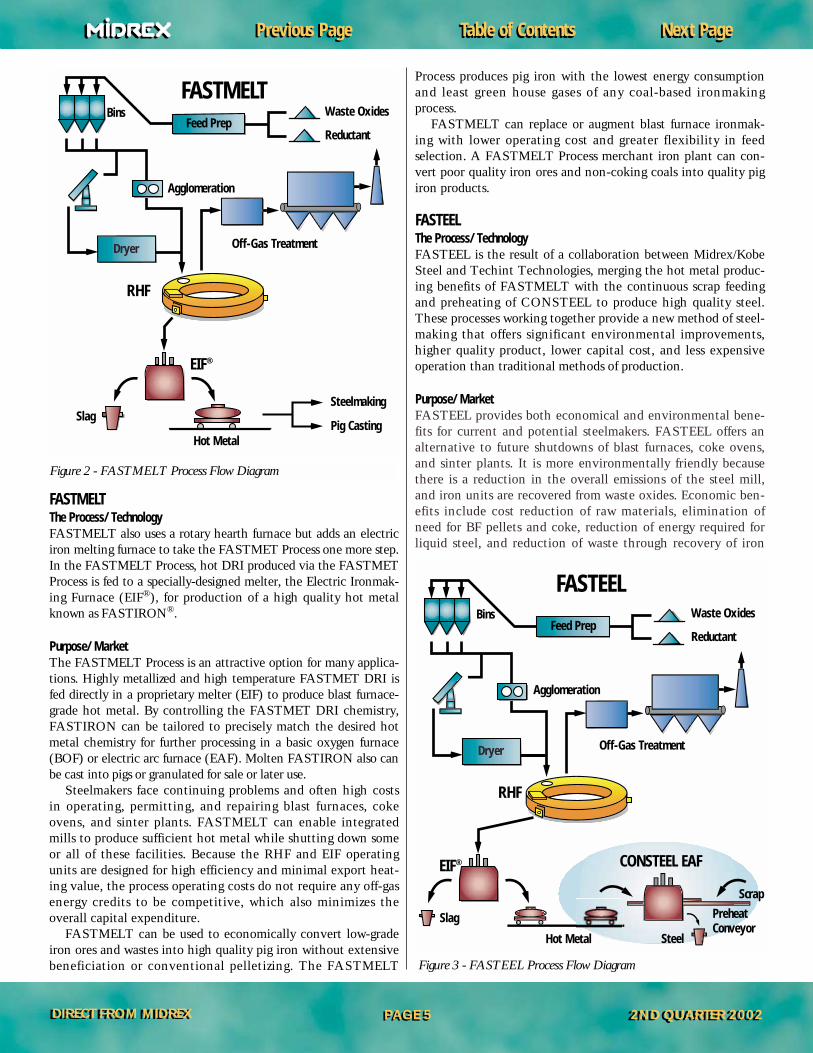
Table of ContentsTable of Contents Next PageNext PagePrevious PagePrevious Page
DIRECT FROM MIDREXDIRECT FROM MIDREX 2ND QUARTER 2002 2ND QUARTER 2002 PAGE 5PAGE 5
FASTMELTThe Process/Technology FASTMELT also uses a rotary hearth furnace but adds an electriciron melting furnace to take the FASTMET Process one more step.In the FASTMELT Process, hot DRI produced via the FASTMETProcess is fed to a specially-designed melter, the Electric Ironmak-ing Furnace (EIF®), for production of a high quality hot metalknown as FASTIRON®.
Purpose/MarketThe FASTMELT Process is an attractive option for many applica-tions. Highly metallized and high temperature FASTMET DRI isfed directly in a proprietary melter (EIF) to produce blast furnace-grade hot metal. By controlling the FASTMET DRI chemistry,FASTIRON can be tailored to precisely match the desired hotmetal chemistry for further processing in a basic oxygen furnace(BOF) or electric arc furnace (EAF). Molten FASTIRON also canbe cast into pigs or granulated for sale or later use.
Steelmakers face continuing problems and often high costsin operating, permitting, and repairing blast furnaces, cokeovens, and sinter plants. FASTMELT can enable integratedmills to produce sufficient hot metal while shutting down someor all of these facilities. Because the RHF and EIF operatingunits are designed for high efficiency and minimal export heat-ing value, the process operating costs do not require any off-gasenergy credits to be competitive, which also minimizes theoverall capital expenditure.
FASTMELT can be used to economically convert low-gradeiron ores and wastes into high quality pig iron without extensivebeneficiation or conventional pelletizing. The FASTMELT
Process produces pig iron with the lowest energy consumptionand least green house gases of any coal-based ironmakingprocess.
FASTMELT can replace or augment blast furnace ironmak-ing with lower operating cost and greater flexibility in feed selection. A FASTMELT Process merchant iron plant can con-vert poor quality iron ores and non-coking coals into quality pigiron products.
FASTEELThe Process/Technology FASTEEL is the result of a collaboration between Midrex/KobeSteel and Techint Technologies, merging the hot metal produc-ing benefits of FASTMELT with the continuous scrap feedingand preheating of CONSTEEL to produce high quality steel.These processes working together provide a new method of steel-making that offers significant environmental improvements,higher quality product, lower capital cost, and less expensiveoperation than traditional methods of production.
Purpose/MarketFASTEEL provides both economical and environmental bene-fits for current and potential steelmakers. FASTEEL offers analternative to future shutdowns of blast furnaces, coke ovens,and sinter plants. It is more environmentally friendly becausethere is a reduction in the overall emissions of the steel mill,and iron units are recovered from waste oxides. Economic ben-efits include cost reduction of raw materials, elimination ofneed for BF pellets and coke, reduction of energy required forliquid steel, and reduction of waste through recovery of iron
Figure 2 - FASTMELT Process Flow Diagram
Figure 3 - FASTEEL Process Flow Diagram
Feed Prep
Dryer
SteelmakingSlag
Hot Metal
Bins
Agglomeration
Waste Oxides
Reductant
Off-Gas Treatment
RHF
Pig Casting
EIF®
Feed Prep
Dryer
Slag
SteelHot Metal
Scrap
Bins
Agglomeration
Waste Oxides
Reductant
Off-Gas Treatment
Preheat Conveyor
RHF
EIF® CONSTEEL EAF
FASTMELT
FASTEEL
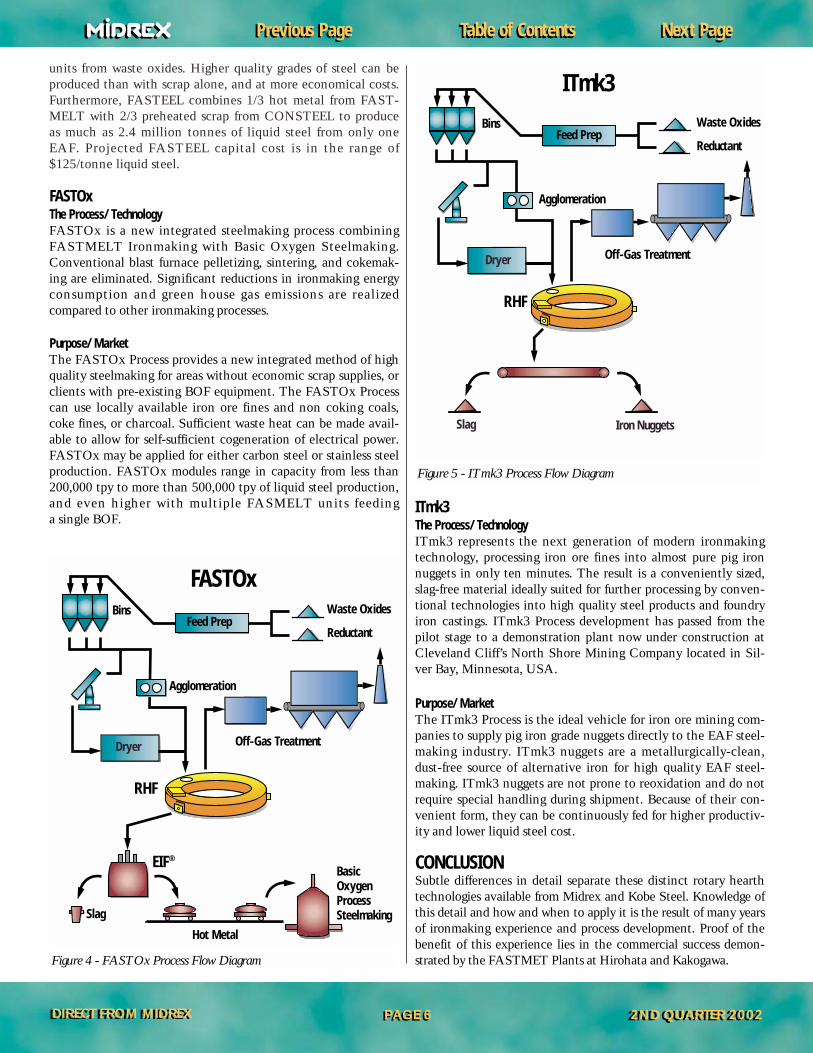
Table of ContentsTable of Contents Next PageNext PagePrevious PagePrevious Page
DIRECT FROM MIDREXDIRECT FROM MIDREX 2ND QUARTER 2002 2ND QUARTER 2002 PAGE 6PAGE 6
units from waste oxides. Higher quality grades of steel can beproduced than with scrap alone, and at more economical costs.Furthermore, FASTEEL combines 1/3 hot metal from FAST-MELT with 2/3 preheated scrap from CONSTEEL to produceas much as 2.4 million tonnes of liquid steel from only oneEAF. Projected FASTEEL capital cost is in the range of$125/tonne liquid steel.
FASTOxThe Process/Technology FASTOx is a new integrated steelmaking process combiningFASTMELT Ironmaking with Basic Oxygen Steelmaking. Conventional blast furnace pelletizing, sintering, and cokemak-ing are eliminated. Significant reductions in ironmaking energyconsumption and green house gas emissions are realized compared to other ironmaking processes.
Purpose/MarketThe FASTOx Process provides a new integrated method of highquality steelmaking for areas without economic scrap supplies, orclients with pre-existing BOF equipment. The FASTOx Processcan use locally available iron ore fines and non coking coals,coke fines, or charcoal. Sufficient waste heat can be made avail-able to allow for self-sufficient cogeneration of electrical power.FASTOx may be applied for either carbon steel or stainless steelproduction. FASTOx modules range in capacity from less than200,000 tpy to more than 500,000 tpy of liquid steel production,and even higher with multiple FASMELT units feeding a single BOF.
ITmk3The Process/Technology ITmk3 represents the next generation of modern ironmakingtechnology, processing iron ore fines into almost pure pig ironnuggets in only ten minutes. The result is a conveniently sized,slag-free material ideally suited for further processing by conven-tional technologies into high quality steel products and foundryiron castings. ITmk3 Process development has passed from thepilot stage to a demonstration plant now under construction atCleveland Cliff’s North Shore Mining Company located in Sil-ver Bay, Minnesota, USA.
Purpose/MarketThe ITmk3 Process is the ideal vehicle for iron ore mining com-panies to supply pig iron grade nuggets directly to the EAF steel-making industry. ITmk3 nuggets are a metallurgically-clean,dust-free source of alternative iron for high quality EAF steel-making. ITmk3 nuggets are not prone to reoxidation and do notrequire special handling during shipment. Because of their con-venient form, they can be continuously fed for higher productiv-ity and lower liquid steel cost.
CONCLUSIONSubtle differences in detail separate these distinct rotary hearthtechnologies available from Midrex and Kobe Steel. Knowledge ofthis detail and how and when to apply it is the result of many yearsof ironmaking experience and process development. Proof of thebenefit of this experience lies in the commercial success demon-strated by the FASTMET Plants at Hirohata and Kakogawa.Figure 4 - FASTOx Process Flow Diagram
Figure 5 - ITmk3 Process Flow Diagram
Feed Prep
Dryer
Slag
Hot Metal
Bins
Agglomeration
Waste Oxides
Reductant
Off-Gas Treatment
BasicOxygenProcessSteelmaking
RHF
Feed Prep
Dryer
Slag Iron Nuggets
Bins
Agglomeration
Waste Oxides
Reductant
Off-Gas Treatment
RHF
EIF®
ITmk3
FASTOx
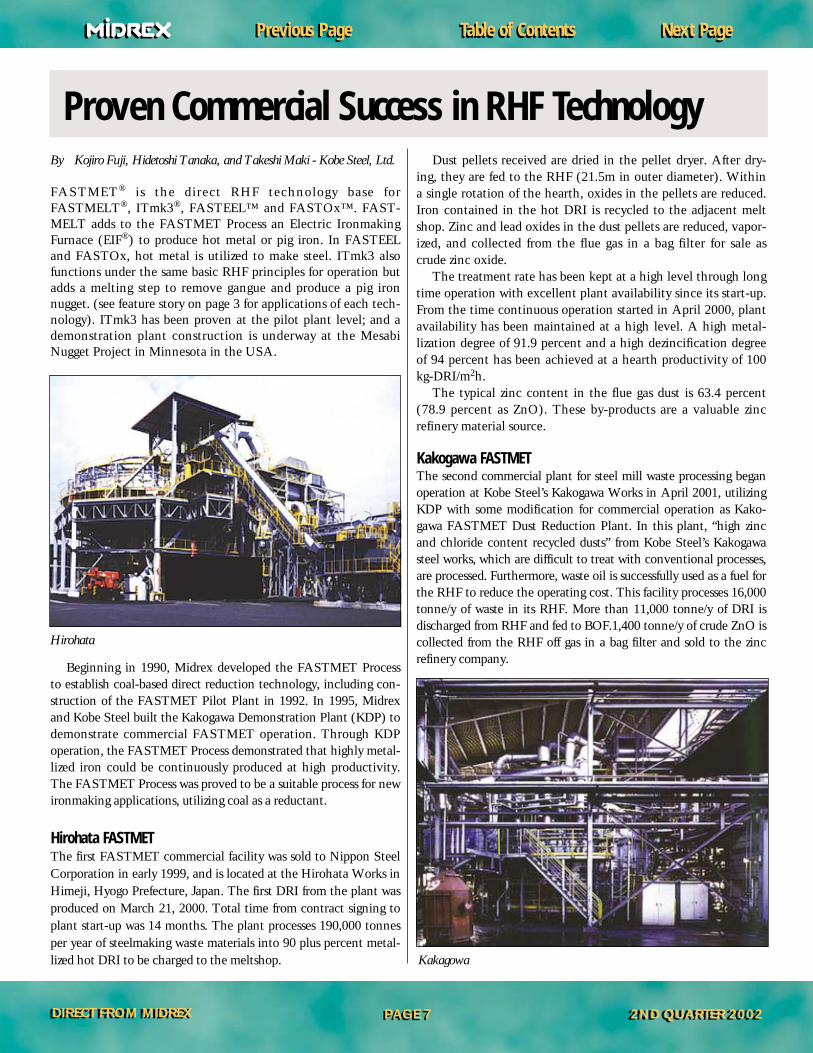
Table of ContentsTable of Contents Next PageNext PagePrevious PagePrevious Page
DIRECT FROM MIDREXDIRECT FROM MIDREX 2ND QUARTER 2002 2ND QUARTER 2002 PAGE 7PAGE 7
By Kojiro Fuji, Hidetoshi Tanaka, and Takeshi Maki - Kobe Steel, Ltd.
FASTMET® is the direct RHF technology base for FASTMELT®, ITmk3®, FASTEEL™ and FASTOx™. FAST-MELT adds to the FASTMET Process an Electric IronmakingFurnace (EIF®) to produce hot metal or pig iron. In FASTEELand FASTOx, hot metal is utilized to make steel. ITmk3 alsofunctions under the same basic RHF principles for operation butadds a melting step to remove gangue and produce a pig ironnugget. (see feature story on page 3 for applications of each tech-nology). ITmk3 has been proven at the pilot plant level; and ademonstration plant construction is underway at the MesabiNugget Project in Minnesota in the USA.
Beginning in 1990, Midrex developed the FASTMET Processto establish coal-based direct reduction technology, including con-struction of the FASTMET Pilot Plant in 1992. In 1995, Midrexand Kobe Steel built the Kakogawa Demonstration Plant (KDP) todemonstrate commercial FASTMET operation. Through KDPoperation, the FASTMET Process demonstrated that highly metal-lized iron could be continuously produced at high productivity.The FASTMET Process was proved to be a suitable process for newironmaking applications, utilizing coal as a reductant.
Hirohata FASTMET The first FASTMET commercial facility was sold to Nippon SteelCorporation in early 1999, and is located at the Hirohata Works inHimeji, Hyogo Prefecture, Japan. The first DRI from the plant wasproduced on March 21, 2000. Total time from contract signing toplant start-up was 14 months. The plant processes 190,000 tonnesper year of steelmaking waste materials into 90 plus percent metal-lized hot DRI to be charged to the meltshop.
Dust pellets received are dried in the pellet dryer. After dry-ing, they are fed to the RHF (21.5m in outer diameter). Withina single rotation of the hearth, oxides in the pellets are reduced.Iron contained in the hot DRI is recycled to the adjacent meltshop. Zinc and lead oxides in the dust pellets are reduced, vapor-ized, and collected from the flue gas in a bag filter for sale ascrude zinc oxide.
The treatment rate has been kept at a high level through longtime operation with excellent plant availability since its start-up.From the time continuous operation started in April 2000, plantavailability has been maintained at a high level. A high metal-lization degree of 91.9 percent and a high dezincification degreeof 94 percent has been achieved at a hearth productivity of 100kg-DRI/m2h.
The typical zinc content in the flue gas dust is 63.4 percent(78.9 percent as ZnO). These by-products are a valuable zincrefinery material source.
Kakogawa FASTMET The second commercial plant for steel mill waste processing beganoperation at Kobe Steel’s Kakogawa Works in April 2001, utilizingKDP with some modification for commercial operation as Kako-gawa FASTMET Dust Reduction Plant. In this plant, “high zincand chloride content recycled dusts” from Kobe Steel’s Kakogawasteel works, which are difficult to treat with conventional processes,are processed. Furthermore, waste oil is successfully used as a fuel forthe RHF to reduce the operating cost. This facility processes 16,000tonne/y of waste in its RHF. More than 11,000 tonne/y of DRI isdischarged from RHF and fed to BOF.1,400 tonne/y of crude ZnO iscollected from the RHF off gas in a bag filter and sold to the zincrefinery company.
Hirohata
Kakagowa
Proven Commercial Success in RHF Technology

Table of ContentsTable of Contents Next PageNext PagePrevious PagePrevious Page
DIRECT FROM MIDREXDIRECT FROM MIDREX 2ND QUARTER 2002 2ND QUARTER 2002 PAGE 8PAGE 8
By Osamu Tsuge, Shoichi Kikuchi, Koji Tokuda, Shuzo Ito, Isao Kobayashi and Akira Uragami, Kobe Steel, Ltd., Osaka, Japan
This article was adapted from the well-received paper presented at the 2002ISS Conference held in Nashville, Tennessee, USA, and focuses on thenew revolutionary ITmk3® ironmaking process. This article examines howITmk3 has progressed to the demonstation plant stage by the success of thepilot plant tests at Kakogawa Works, Japan. High quality iron nuggetswere produced directly from fine ore and coal, providing operation technol-ogy during the 21 days continuous operation recorded.
IntroductionThe new innovative ITmk3® ironmaking process produces ironnuggets within the rotary hearth furnace directly from fine oreand coal using carbon composite iron ore agglomerates. The keyfeature of the process is the clear separation of metal and slagwith a rapid reaction rate at a relatively low operation tempera-ture. This ability suggests a great potential for ITmk3 to supplymelt shops with a pure iron source as a scrap substitute, while alsoempowering mining sites to export a pure iron to steelmakers as acompetitive value-added product.
Successful Iron Nuggets Production atITmk3® Pilot Plant
Successful Iron Nuggets Production atITmk3® Pilot Plant
Figure 1 - ITmk3 Process Flow
Iron Oxide
Binder(Coal)
Mixer
Pelletizer
Dryer
Feed Preparation
Combustion Air Gas CleaningSystem Fan
Stack
Offgas
Offgas Treatment
Product Discharge Burners
ReductionRotary Hearth Furnace
Burner FuelHot Product Stream
Reductant
Combustion AirRecuperator
Separation/Screening
Iron Nuggets Slag
Product Cooling

Table of ContentsTable of Contents Next PageNext PagePrevious PagePrevious Page
DIRECT FROM MIDREXDIRECT FROM MIDREX 2ND QUARTER 2002 2ND QUARTER 2002 PAGE 9PAGE 9
To confirm process concept and to industrialize the technol-ogy for scale-up, a pilot plant was constructed at KakogawaWorks of Kobe Steel, Ltd. The pilot plant was operational innine months, and 21 days of continuous operation was achievedwith production of high quality iron nuggets. A process demon-stration plant is now under construction at Cleveland Cliffs’NorthShore Mine pellet plant in Silver Bay, Minnesota, USA.
Pilot Plant Design ConceptThe furnace configuration was designed based on the reduc-tion/melting behavior of the laboratory tests and optimized bythe evaluation of the atmospheric gas flow using the CFD (com-puter fluid dynamics) model.
Pilot plant operation was planned to optimize operating con-ditions, as well as to test the flexibility of raw material feed,check design database, and obtain operational data for commer-cial plant feasibility study.
The process flow of ITmk3 is shown in Figure 1. The system is composed of agglomeration (pelletizing), drying, reduction/melt-ing furnace, product treatment, and off gas system. The ITmk3reduction/melting rotary hearth furnace was newly designed and constructed. Other systems from the FASTMET demonstra-tion plant were modified for use. The main features are listed inTable 1. An overview of the plant is shown in Figure 2.
Pilot Plant OperationThe raw materials, which were tested in the pilot plant, areshown in Tables 2 and 3. The fine ore for pellet feed was usedwithout pre-treatment. In this operation, carbon composite pel-lets using hematite and magnetite concentrates were producedby the disk pelletizer. Medium volatile coals from US andCanada were used as the reductant coal, as these were easilyavailable in the Kakogawa Works. The coal was pulverized usingexisting equipment from the FASTMET demo plant.
In the feed zone (see Figure 3), soot was generated bydevolatilization of volatile matter included in the reductant coal.This soot is effectively used as the fuel within the rotary hearth fur-nace. In the reduction zone, the pellets were heated and the solidstate reduction progressed calmly under the controlled tempera-ture, so not to melt the pellets. Additional combustion air
Figure 4 - Change of Furnace Temperature and Fuel Consumption
Coal Fixed C VM Ash S
D 69.39 21.25 9.63 0.334
E 71.50 19.90 8.60 0.53
F 72.04 18.09 9.65 0.219
Table 3 - Proximate Analysis of Reductant Coal
1.0
0.8
0.6
0.4
0.2
00 5 10 15 20 25
Tem
pera
ture
, Fue
l (-)
Time (Day)
Melting Zone Temp.
Reduction Zone Temp.
Feed Zone Temp.
Fuel
Ore Total Fe FeO CaO SiO2 Al2O3 MgO
A 69.20 30.56 0.45 1.81 0.51 0.45
B 67.86 0.07 0.10 1.56 0.61 0.12
C 66.77 1.10 0.17 1.40 0.35 0.03
Table 2 - Chemical Compositions of Raw Materials (wt %)
Figure 3 - Inside View of the Rotary Hearth Furnace
Feed Zone Reduction Zone Melting Zone
Figure 2 - ITmk3 Plant at Kakagowa Works
Reactor Rotary Hearth Furnace
Hearth Center Diameter 3.2 m
Effective Width 0.8 m
Design Capacity 350 kg/hr
Table 1 - Main Features of ITmk3 Kakogawa Pilot Plant
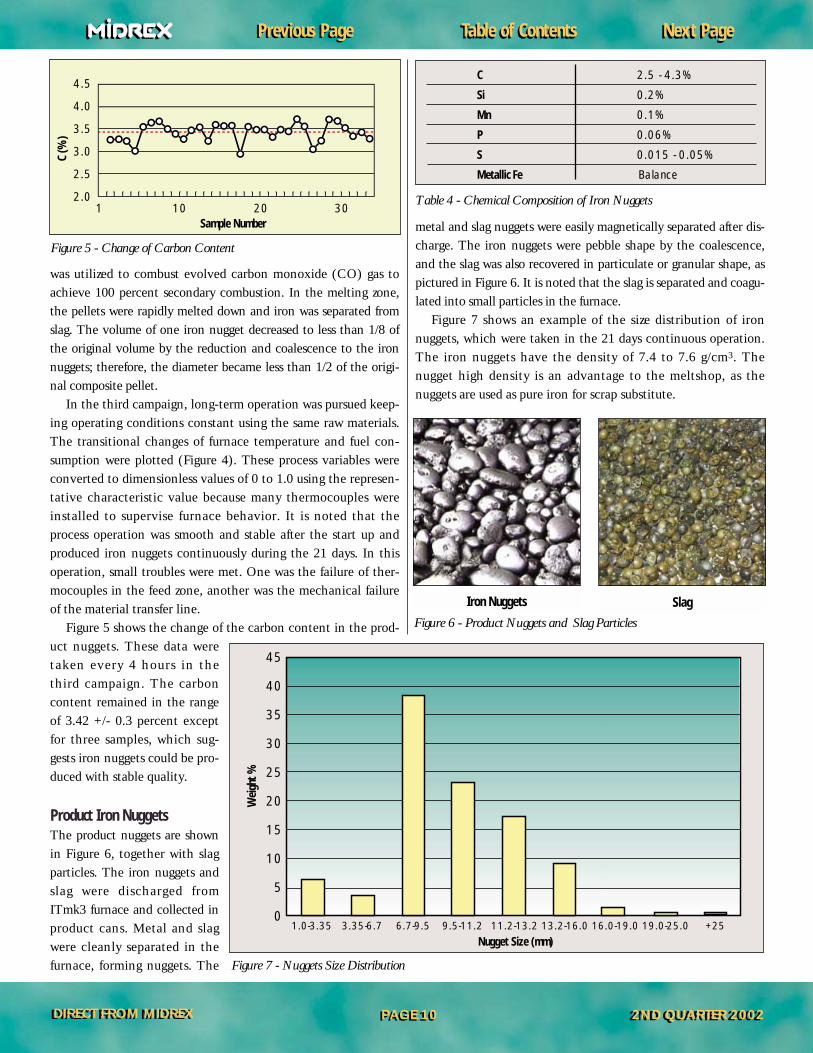
Table of ContentsTable of Contents Next PageNext PagePrevious PagePrevious Page
DIRECT FROM MIDREXDIRECT FROM MIDREX 2ND QUARTER 2002 2ND QUARTER 2002 PAGE 10PAGE 10
was utilized to combust evolved carbon monoxide (CO) gas toachieve 100 percent secondary combustion. In the melting zone,the pellets were rapidly melted down and iron was separated fromslag. The volume of one iron nugget decreased to less than 1/8 ofthe original volume by the reduction and coalescence to the ironnuggets; therefore, the diameter became less than 1/2 of the origi-nal composite pellet.
In the third campaign, long-term operation was pursued keep-ing operating conditions constant using the same raw materials.The transitional changes of furnace temperature and fuel con-sumption were plotted (Figure 4). These process variables wereconverted to dimensionless values of 0 to 1.0 using the represen-tative characteristic value because many thermocouples wereinstalled to supervise furnace behavior. It is noted that theprocess operation was smooth and stable after the start up andproduced iron nuggets continuously during the 21 days. In thisoperation, small troubles were met. One was the failure of ther-mocouples in the feed zone, another was the mechanical failureof the material transfer line.
Figure 5 shows the change of the carbon content in the prod-uct nuggets. These data weretaken every 4 hours in thethird campaign. The carboncontent remained in the rangeof 3.42 +/- 0.3 percent exceptfor three samples, which sug-gests iron nuggets could be pro-duced with stable quality.
Product Iron NuggetsThe product nuggets are shownin Figure 6, together with slagparticles. The iron nuggets andslag were discharged fromITmk3 furnace and collected inproduct cans. Metal and slagwere cleanly separated in thefurnace, forming nuggets. The
metal and slag nuggets were easily magnetically separated after dis-charge. The iron nuggets were pebble shape by the coalescence,and the slag was also recovered in particulate or granular shape, aspictured in Figure 6. It is noted that the slag is separated and coagu-lated into small particles in the furnace.
Figure 7 shows an example of the size distribution of ironnuggets, which were taken in the 21 days continuous operation.The iron nuggets have the density of 7.4 to 7.6 g/cm3. Thenugget high density is an advantage to the meltshop, as thenuggets are used as pure iron for scrap substitute.
C 2.5 - 4.3%
Si 0.2%
Mn 0.1%
P 0.06%
S 0.015 - 0.05%
Metallic Fe Balance
Table 4 - Chemical Composition of Iron Nuggets
Figure 6 - Product Nuggets and Slag Particles
SlagIron Nuggets
Figure 7 - Nuggets Size Distribution
Figure 5 - Change of Carbon Content
4.5
4.0
3.5
3.0
2.5
2.01 10 20 30
C (%
)
Sample Number
Weig
ht %
45
40
35
30
25
20
15
10
5
01.0-3.35 3.35-6.7 6.7-9.5 9.5-11.2 11.2-13.2 13.2-16.0 16.0-19.0 19.0-25.0 +25
Nugget Size (mm)
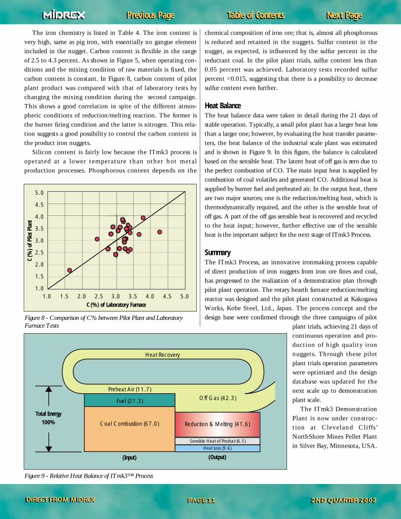
Table of ContentsTable of Contents Next PageNext PagePrevious PagePrevious Page
DIRECT FROM MIDREXDIRECT FROM MIDREX 2ND QUARTER 2002 2ND QUARTER 2002 PAGE 11PAGE 11
The iron chemistry is listed in Table 4. The iron content isvery high, same as pig iron, with essentially no gangue elementincluded in the nugget. Carbon content is flexible in the rangeof 2.5 to 4.3 percent. As shown in Figure 5, when operating con-ditions and the mixing condition of raw materials is fixed, thecarbon content is constant. In Figure 8, carbon content of pilotplant product was compared with that of laboratory tests bychanging the mixing condition during the second campaign.This shows a good correlation in spite of the different atmos-pheric conditions of reduction/melting reaction. The former isthe burner firing condition and the latter is nitrogen. This rela-tion suggests a good possibility to control the carbon content inthe product iron nuggets.
Silicon content is fairly low because the ITmk3 process is operated at a lower temperature than other hot metal production processes. Phosphorous content depends on the
chemical composition of iron ore; that is, almost all phosphorousis reduced and retained in the nuggets. Sulfur content in thenugget, as expected, is influenced by the sulfur percent in thereductant coal. In the pilot plant trials, sulfur content less than0.05 percent was achieved. Laboratory tests recorded sulfur percent <0.015, suggesting that there is a possibility to decrease sulfur content even further.
Heat BalanceThe heat balance data were taken in detail during the 21 days ofstable operation. Typically, a small pilot plant has a larger heat lossthan a larger one; however, by evaluating the heat transfer parame-ters, the heat balance of the industrial scale plant was estimatedand is shown in Figure 9. In this figure, the balance is calculatedbased on the sensible heat. The latent heat of off gas is zero due tothe perfect combustion of CO. The main input heat is supplied bycombustion of coal volatiles and generated CO. Additional heat issupplied by burner fuel and preheated air. In the output heat, thereare two major sources; one is the reduction/melting heat, which isthermodynamically required, and the other is the sensible heat ofoff gas. A part of the off gas sensible heat is recovered and recycledto the heat input; however, further effective use of the sensibleheat is the important subject for the next stage of ITmk3 Process.
SummaryThe ITmk3 Process, an innovative ironmaking process capable of direct production of iron nuggets from iron ore fines and coal,has progressed to the realization of a demonstration plan throughpilot plant operation. The rotary hearth furnace reduction/meltingreactor was designed and the pilot plant constructed at KakogawaWorks, Kobe Steel, Ltd., Japan. The process concept and thedesign base were confirmed through the three campaigns of pilot
plant trials, achieving 21 days ofcontinuous operation and pro-duction of high quality ironnuggets. Through these pilotplant trials operation parameterswere optimized and the designdatabase was updated for thenext scale up to demonstrationplant scale.
The ITmk3 DemonstrationPlant is now under construc-tion at Cleveland Cliffs’NorthShore Mines Pellet Plantin Silver Bay, Minnesota, USA.
Figure 8 - Comparison of C% between Pilot Plant and Laboratory Furnace Tests
5.0
4.5
4.0
3.5
3.0
2.5
2.0
1.5
1.01.0 1.5 2.0 2.5 3.0 3.5 4.0 4.5 5.0
C (%
) of P
ilot P
lant
C (%) of Laboratory Furnace
Figure 9 - Relative Heat Balance of ITmk3™ Process
Heat Recovery
Preheat Air (11.7)
Sensible Heat of Product (6.5)Heat Loss (9.6)
Off Gas (42.3)
Reduction & Melting (41.6)
Fuel (21.3)
Coal Combustion (67.0)
Total Energy100%
(Input) (Output)

Table of ContentsTable of Contents Next PageNext PagePrevious PagePrevious Page
Construction of Mesabi Nugget Plant UnderwayITmk3® Process to be Demonstrated in MinnesotaKobe Steel, Ltd. has signed a final agreement with Mesabi Nugget, LLC for the construction and operation of an ITmk3®
demonstration plant in northeastern Minnesota (USA). With financing and equity participation in the project now completed,engineering and construction of the demonstration plant has begun.
Engineering and project planning has begun at Midrex Technologies, Inc. with construction scheduled to begin in August.After the plant is completed in March 2003, plans call for the facility to be operated for one year.
Midrex in cooperation with Kobe Steel, Ltd., its parent company and developer of the new process known as ITmk3, willengineer, design, and supply proprietary equipment and participate in field testing for the project in Silver Bay, Minnesota. Thisproject is intended to further develop the ITmk3 Process at a scaled-up level in anticipation of commercial operation.
The ITmk3 Process is a new ironmaking technology that, in a rotary hearth furnace, turns iron ore fines and pulverized coalinto iron nuggets of the same quality as blast furnace pig iron. Energy efficient and environmentally friendly, the ITmk3 Processemits 20 percent less carbon dioxide than blast furnace operations. Reduction, melting and slag removal takes only about 10minutes. In addition, capital investment is projected at roughly half the cost of conventional ironmaking technologies. Ironnuggets could also provide an attractive mineral processing alternative for mining companies.
The 25,000-ton-per-year demonstration plant will be built at the Northshore Mining taconite plant in Silver Bay owned byCleveland-Cliffs Inc. The project is funded by Kobe Steel and other equity investors, as well as loans from the Minnesota Minerals 21st Century Fund and Minnesota’s Iron Range Resources and Rehabilitation Agency.
Kobe Steel and its subsidiary Midrex Technologies, Inc. began research on the ITmk3 Process in 1996. A pilot plant with aproduction capacity of 3,000 metric tons per year was built at Kobe Steel’s Kakogawa Works. Test operations carried outbetween October 1999 and December 2000 successfully produced iron nuggets under continuous operation.
Midrex News & ViewsMidrex News & Views
DIRECT FROM MIDREXDIRECT FROM MIDREX 2ND QUARTER 2002 2ND QUARTER 2002 PAGE 12PAGE 12
Techint, Kobe Steel and Midrex Reach Worldwide Agreementon New Iron and Steelmaking Technologies Kobe Steel, Techint and Midrex have signed an agreement that creates a strategic alliance for the marketing and supply ofFASTMET®, FASTMELT® , and FASTEEL™ projects worldwide.
Under the agreement Techint will supply the rotary hearth furnaces and melting/smelting equipment, which are integralparts of the FASTMET and FASTMELT Processes. "This agreement means that we can focus our attention on providing themost effective equipment design for each plant configuration," said Gianluigi Nova, CEO of Techint Technologies. "It will alsoallow us to approach our customers as a team, working together to provide the best solution possible in each market segment".
The agreement also covers cooperation for the marketing of the FASTEEL Process, which combines the FASTMELT Processwith Techint’s CONSTEEL‚ system for continuous scrap feeding and preheating.
"The FASTMET, FASTMELT and FASTEEL Processes will become increasingly popular as mills look to better ways of pro-ducing liquid steel," said Steve Okushima, Group Executive Vice President of Kobe Steel. "Techint is a leading supplier of melt-ing and smelting equipment, and they have built more rotary hearth furnaces than any other supplier, so we feel very confidentin their ability to deliver quality equipment for these processes."
In October 2001 Techint acquired the assets of EMCI from Midrex Technologies to further enhance the capabilities of theTechint meltshop division. In April 2002, Techint received a contract from Midrex to build the rotary hearth furnace that willbe a part of the Mesabi Nugget demonstration plant for Kobe Steel’s ITmk3® technology for producing blast furnace-grade pigiron in a form that can be continuously fed to the EAF.
Table of ContentsTable of Contents Next PageNext PagePrevious PagePrevious Page
Midrex Technologies, Inc. and its sister company PSI havepassed their upgrade audit with Underwriter Laboratories (UL)to be certified to the new standard, ISO 9001-2000.
In addition to the new certification, PSI has also success-fully expanded its scope to include MRO [Maintenance,Repair and Operations supply] purchasing and TechnicalStaffing Services.
ISO 9001-2000 is an international standard for Quality Man-agement Systems used to assess a company’s ability to meet cus-tomer and applicable regulatory requirements and thereby addresscustomer satisfaction. It is now the only standard in the ISO 9000family against which third-party certification can be carried.
The new scope of registration for Midrex Enterprises, Inc,
which includes both Midrex Technologies, Inc. and ProfessionalServices International, reads:
“The provision of contracted engineering, technical staffingservices, and equipment packages for industrial plants. The pro-curement of the original plant equipment for these engineeredplants and the supply of replacement parts.”
What this means is that any service provided by Midrex Tech-nologies or PSI will be executed under our Quality ManagementSystem to the requirements of ISO 9001-2000. This includesengineering, project management, procurement, field services,technology studies, etc. for both our traditional direct reductionbusiness, but also for any new business client in energy, environ-mental, or other industries.
Midrex Solutions® Signs Additional Contracts Midrex Solutions® has recently received several new contracts for small capital projects that include engineering for expansions,custom equipment design, and productivity improvements. The new contracts add to the more than 20 small projects the grouphas contracted since its inception in January 2001.
Midrex Solutions was launched to assist existing MIDREX® Direct ReductionPlants to enhance their performance and to execute small capital projects involv-ing engineered improvements. The work executed to-date has included engineeringservices, process training, equipment/material supply, and technical field services.As the direct reduction market improves, Midrex Solutions expects to continue itssuccess and work with an increasing number of MIDREX Plants.
The group has received a favorable response from the marketplace and has prepared more than 75 proposals for engineeredplant solutions and technical assistance.
Midrex News & ViewsMidrex News & Views
®
Midrex Certified to New ISO 9001-2000 Standard
DIRECT FROM MIDREXDIRECT FROM MIDREX 2ND QUARTER 2002 2ND QUARTER 2002 PAGE 13PAGE 13
Midrex Announces Donald Beggs Scholarship RecipientsMidrex is pleased to announce Patrick Elliot and Susan Metius as the 2002 recipients of the Donald Beggs Scholarship Program.
Named for Donald Beggs, who conceived the idea for the MIDREX® Direct Reduction Process in the early 1960s, this scholarshipis awarded to college-age sons and daughters of Midrex employees and is meant toacknowledge and reward the hard work and academics of these students.
Patrick Elliot is the son of Antonio Elliot, Manager of Technical Services atMidrex. He is currently in his last year in high school, and will attend the Univer-sity of North Carolina at Chapel Hill next school year in the Honors program,working towards a degree in Biology and Chemistry. Patrick was goalkeeper on hishigh school soccer team, which won the state of North Carolina 2A high schoolchampionship this past year.
Ms. Metius is the daughter of Gary Metius, Manager-New Technology Programs at Midrex. Susan is a junior at the University of North Carolina atWilmington, majoring in biology. She plans to work in the medical and publichealth field after graduation. She is very active in UNCW’s PanhellenicAffairs Council and has received student leadership awards the last two yearsfor her activities. She also spends every other weekend working as a nurse’s aid in the emergency room of the Cape Fear Memor-ial Hospital in Wilmington, North Carolina, USA.
Congratulations to Patrick and Susan, and thank you to all applicants who participated in this year’s program.
Patrick ElliotSusan Metius

Midrex News & ViewsMidrex News & Views
Midrex Takes Steps TowardsDiversificationMidrex Technologies, Inc. took a significant step in its diversifi-cation effort during May with the signing of business develop-ment agreements with Industrial Recovery Systems Inc. (IR Sys-tems) and ClearStack Combustion Corporation. Over the nextseveral months, Midrex will determine the feasibility of long-term business relationships with both companies.
IR SystemsIR Systems is a four-year old, Charlotte, NC-based environmen-tal services company that specializes in the decontamination ofsoils, sludges, tank bottoms, and process wastes. They are thedeveloper and owner of the patented Matrix Constituent Sepa-rator (MCS) system, a low temperature thermal desorber(LTTD) technology that is currently in commercial use inrefineries, manufacturing facilities, and central waste treatmentsites in various parts of the world, including the USA.
Midrex and and its sister company, Professional ServicesInternational Inc. (PSI), will assist IR Systems in conducting amajor remediation project for the US Government. The workincludes preparing an engineering package for the MCS andarranging the fabrication and shipping of multiple MCS units tothe site. Additionally, Midrex and PSI are helping IR Systemswith testing, marketing, and project development.
The MCS system is a static tray, batch process that heats thecontaminated material with infrared radiation and draws hot airthrough it under vacuum. The vacuum reduces the boilingpoints of the contaminants, causing a phase change from liquidor solid to vapors. The vapors are transported out of the treat-ment chamber and condensed into liquid in the air emissioncontrol system.
The MCS system is an ideal remediation solution for limitedaccess, restricted space, and/or high visibility sites. It is modular,portable, emits no dust during operation, and is economically
feasible for small or large projects. The MCS system is effectivefor treatment of soils impacted with hazardous substances, petro-leum products including fuels, volatile and semi-volatile com-pounds, chlorinated solvents, and other environmentally regu-lated chemicals.
IR Systems has won numerous awards for the MCS technol-ogy including the Malaysian Government Hibiscus Award andthe Governor’s Award from the North Carolina Society of Pro-fessional Engineers.
ClearStack Combustion CorporationClearStack, located in Springfield, IL, specializes in technologiesfor lowering NOx and sulfur emissions in coal-fired boilers.ClearStack’s main product is the Ashworth Combustor™, a slag-ging coal gasifier that incorporates a three-stage combustiontechnique. This technique reduces three major air pollutants ofcoal combustion: NOx, SO2, and particulate. The AshworthCombustor provides an economical means for reducing NOxand sulfur emissions to meet the new, more stringent regulations.It enables utilities to burn higher sulfur coals and continue oper-ating intermediate-sized coal-fired plants.
A demonstration-scale Ashworth Combustor has beeninstalled at the Illinois Department of Human Services LincolnDevelopment Center in Lincoln, Illinois, USA. The plant willbe started up in late June, and ClearStack is now approachingclients for the first commercial installation.
The agreement calls for Midrex to support ClearStack at theLincoln Demo Plant, with project development, and in technol-ogy management, as part of a due diligence effort. The ultimategoal is for Midrex to be ClearStack’s technology manager,responsible for enhancing and protecting the technology, andensuring it is properly applied for each project.
Several other new business opportunities in the environmentaland energy fields are currently under evaluation.
Midrex Calendar of EventsSept 29th – Oct 2nd – AISE Annual Conference – Nashville, TNMidrex will present and co-author a total of three papers – FASTMET®,Impact of Charge Materials at Georgetown Steel Corp., and Not All RHFTechnology Is Created Equal.
October 20-23 – ILAFA EXPO, 2002 – Cancun, Mexico
November 10-13 – 59th Electric Furnace Conference – Midrex will pre-sent the following papers – Using Oxygen to Make Reducing Gas in theMIDREX® DR Process, Influence of AIS Chemisrty on EAF Steelmaking Economics, Not All Rotary Hearth Furnaces Are Created Equal, andFASTMET® - Proven Process for Steelmill Waste Recovery
Christopher M. Ravenscroft: EditorAdgroup Creative: Graphic Design/Production
DIRECT FROM MIDREX is published quarterly by Midrex Technologies, Inc.,2725 Water Ridge Parkway, Suite 100, Charlotte, North Carolina 28217 U.S.A., Phone: (704)373-1600 Fax:(704)373-1611, Web Site: http://www.midrex.comunder agreement with Midrex International B.V. The publication is distributed worldwide by email to persons interested in the direct reduced iron (DRI) marketand its growing impact on the iron and steel industry.©2002 by Midrex International B.V. To subscribe please register atwww.midrex.com to receive our email service.
MIDREX is a registered trademark of Midrex International B.V. ITmk3 is a registered trademark ofKobe Steel, Ltd.MEGAMOD, SUPER MEGAMOD and HOTLINK are trademarks of Midrex International B.V.FASTMET, FASTMELT and FASTIRON are registered trademarks of Midrex Technologies, Inc.FASTOx™ is a registered trademark of Midrex Technologies, Inc.FASTEEL™ is a registered trademark of Techint Technologies, Inc.
DIRECT FROM MIDREXDIRECT FROM MIDREX 2ND QUARTER 2002 2ND QUARTER 2002 PAGE 14PAGE 14
For additional information or to inquire about specific services,please contact either John Kopfle ([email protected]) or FrankGriscom ([email protected]).
Table of ContentsTable of ContentsPrevious PagePrevious Page