notation part 1 - github pages drawing a diagram does not constitute analysis or design however,...
TRANSCRIPT

Notation Part 1Object Orientated Analysis and Design
Benjamin Kenwright

Version Control
Example
Team Princess3 Members
3 Github Users
e.g.,
Elva1997,
michelle0924hhx,
KimJaeHwang
Each user can join and have lots of repositories.
All members of the common team repository
https://github.com/princess2017

Outline
Review
What do we mean by
Notation?
UML Diagrams
Examples of Notation in
Analysis and Design
Summary/Discussion
Conclusion

Revision Question
Requirements analysis is critical to the
success of a development project.
a) True
b) False
c) Depends upon the size of project

Answer
Answer a)
Explanation: Requirements must be
actionable, measurable, testable, related
to identified business needs or
opportunities, and defined to a level of
detail sufficient for system design
Question
Requirements should specify ‘what’ but
not ‘how’.
a) True
b) False

Answer
Answer: a)
Explanation: ‘What’ refers to a system’s
purpose, while ‘How’ refers to a system’s
structure and behavior.

Diagrams
Drawing a diagram does not
constitute analysis or design
However, diagrams provide
visual aids
Clarifying the concept
Various forms, e.g., 3d-
software, whiteboards,
napkins, and the backs of
envelopes

The Unified Modeling
Language (UML)
Primary modeling language used to
analyze, specify and design software
systems
UML is used to model (i.e., represent)
the system being built


UML has Many Types
Of Diagrams

UMLUnified Modeling Language (UML): is a standardized general-purpose modeling language in the field of object-oriented software engineering. The standard is managed and was created by the Object Management Group (OMG)
UML includes a set of graphic notation techniques to create visual models of object-oriented software-intensive systems.
UML defines different types of diagrams: class (package), object, use case, sequence, collaboration, activity, component, and deployment.
UML has various types of diagrams divided into two main categories

UML Diagrams

UML Diagrams

Two UML Views
of System ModelStatic (or structural) view: emphasizes the static structure of the system using objects, attributes, operations and relationships. It includes class diagrams and composite structure diagrams.
Dynamic (or behavioral) view: emphasizes the dynamic behavior of the system by showing collaborations among objects and changes to the internal states of objects. This view includes sequence diagrams, activity diagrams and state machine diagrams
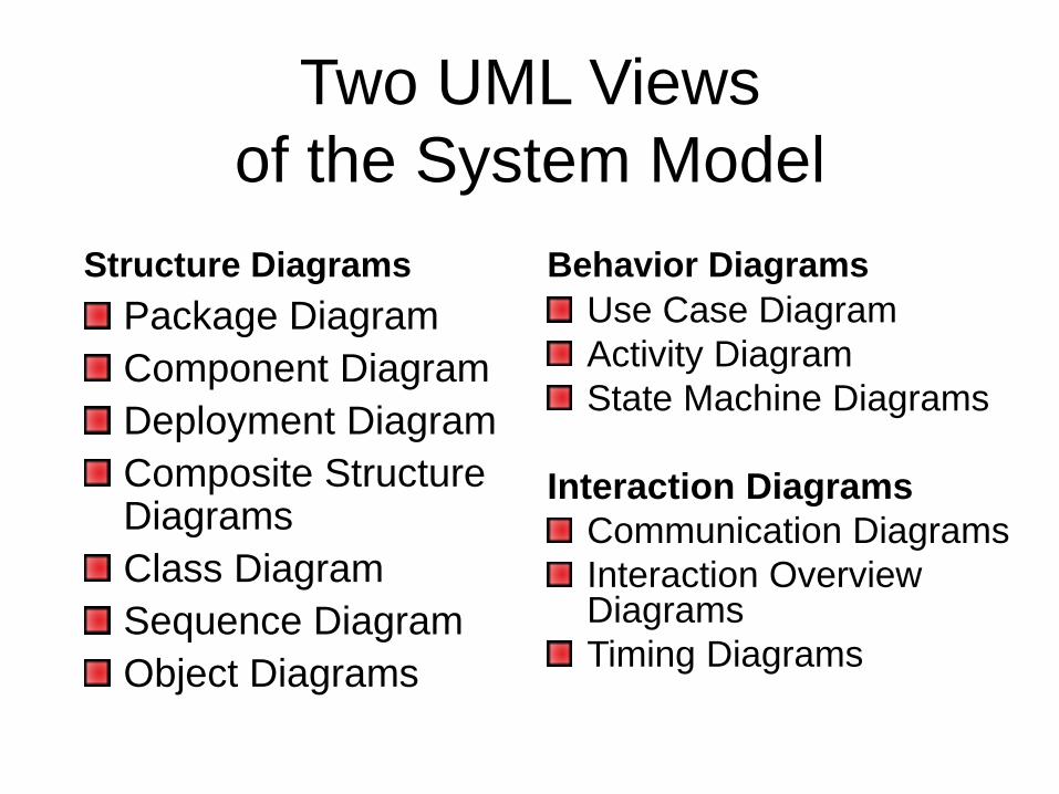
Two UML Views
of the System Model
Structure Diagrams
Package Diagram
Component Diagram
Deployment Diagram
Composite Structure Diagrams
Class Diagram
Sequence Diagram
Object Diagrams
Behavior Diagrams
Use Case Diagram
Activity Diagram
State Machine Diagrams
Interaction Diagrams
Communication Diagrams
Interaction Overview Diagrams
Timing Diagrams

Question
Is a “Class Diagram” a static or dynamic
system model view?
a) Static (or Structural)
b) Dynamic (or Behavioral)

Answer
a) Static (or Structural)
Activity
Write down as many UML diagram
views as you can remember
Also state if they’re Static (Structural) or
Dynamic (Behavioral)

Structure Diagrams
Structure diagrams emphasize the things that must be present in the system being modelled
Since structure diagrams represent the structure, they are used extensively in documenting the software architecture of software systems.
For example, the component diagram describes how a software system is split up into components and shows the dependenciesamong these components.

Behavior Diagrams
Behavior diagrams emphasize what must
happen in the system being modelled
Since behavior diagrams illustrate the
behavior of a system, they are used
extensively to describe the functionality of
software systems
As an example, the activity diagram
describes the business and operational
step-by-step activities of the components
in a system

Plan
Review diagrams in an order in which
one might typically develop them
i.e., instead of reviewing all the structural
and then behavioral diagrams seperately
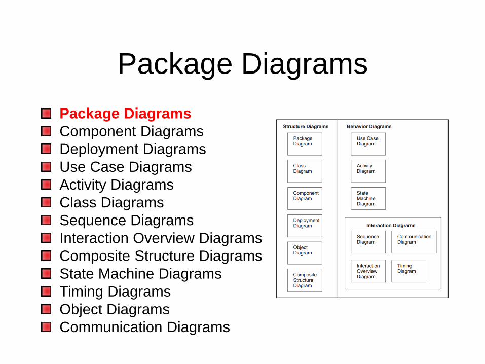
Package Diagrams
Package Diagrams
Component Diagrams
Deployment Diagrams
Use Case Diagrams
Activity Diagrams
Class Diagrams
Sequence Diagrams
Interaction Overview Diagrams
Composite Structure Diagrams
State Machine Diagrams
Timing Diagrams
Object Diagrams
Communication Diagrams

Package Diagram
A package diagram provides the means to organize the artifacts of the development process to clearly present the analysis of the problem space and the associated design
The specific reasons will be varied but will either focus on physically structuring the visual model itself or on clearly representing the model elements through multiple views

Problem (Rational for Package Diagrams)
At the beginning of the project, you only have a limited number of components and everything is simple and beautiful
However, when time flies, more and more components have been created and they start to become unmanageable
As a result, your project becomes hard to navigate and components become difficult to locate when you want to review or make changes

Package Diagrams
to the Rescue
How can we fix this problem?
We can make use of Package Diagrams
to organize the components into
different packages
This helps us categorizing our
components according to their natures,
making them easier to navigated and
locate

Visibility
Public (+) Visible to elements within its
containing package, including
nested packages, and to external
elements
Private (-) Visible only to elements
within its containing package and to
nested packages

Example

Dependencies between UML
elements (including Packages)
Notations for the different types of
relationships are as follows

Example

Component Diagrams
Package Diagrams
Component Diagrams
Deployment Diagrams
Use Case Diagrams
Activity Diagrams
Class Diagrams
Sequence Diagrams
Interaction Overview Diagrams
Composite Structure Diagrams
State Machine Diagrams
Timing Diagrams
Object Diagrams
Communication Diagrams

Component Diagram
A component diagram shows the internal
structure of components and their
dependencies with other components
This diagram provides the representation of
components, collaborating through well-
defined interfaces, to provide system
functionality

Component Notation
Component is a structured classifier, its
detailed assembly can be shown with a
composite structure using
Parts
Ports, and
Connectors

Example

A Component’s Internal
Structure

Deployment Diagrams
Package Diagrams
Component Diagrams
Deployment Diagrams
Use Case Diagrams
Activity Diagrams
Class Diagrams
Sequence Diagrams
Interaction Overview Diagrams
Composite Structure Diagrams
State Machine Diagrams
Timing Diagrams
Object Diagrams
Communication Diagrams

Deployment Diagram
A deployment diagram is used to show
the allocation of artifacts to nodes in the
physical design of a system.
A single deployment diagram represents
a view into the artifact structure of a
system.
The three essential elements of a
deployment diagram are artifacts,
nodes, and their connections.

Example

Question
The three essential elements of a
deployment diagram are:
a) nodes, connections and their elements
b) artifacts, nodes, and their connections
c) elements, relationships and connectors
d) inheritance, relationships and connectors

Answer
b) artifacts, nodes, and their connections

Use Case Diagrams
Package Diagrams
Component Diagrams
Deployment Diagrams
Use Case Diagrams
Activity Diagrams
Class Diagrams
Sequence Diagrams
Interaction Overview Diagrams
Composite Structure Diagrams
State Machine Diagrams
Timing Diagrams
Object Diagrams
Communication Diagrams

Use Case Diagrams
Use case diagrams are used to depict
the context of the system to be built and
the functionality provided by that
system.
They depict who (or what) interacts with
the system.
They show what the outside world
wants the system to do.

Example

Activity Diagrams
Package Diagrams
Component Diagrams
Deployment Diagrams
Use Case Diagrams
Activity Diagrams
Class Diagrams
Sequence Diagrams
Interaction Overview Diagrams
Composite Structure Diagrams
State Machine Diagrams
Timing Diagrams
Object Diagrams
Communication Diagrams

Activity Diagram
Activity diagrams provide visual
depictions of the flow of activities,
whether in a system, business,
workflow, or other process
These diagrams focus on the activities
that are performed and who (or what) is
responsible for the performance of
those activities.

Example

Class Diagrams
Package Diagrams
Component Diagrams
Deployment Diagrams
Use Case Diagrams
Activity Diagrams
Class Diagrams
Sequence Diagrams
Interaction Overview Diagrams
Composite Structure Diagrams
State Machine Diagrams
Timing Diagrams
Object Diagrams
Communication Diagrams

Class Diagram
A class diagram is used to show the existence of classes and their relationships in the logical view of a system
During analysis, class diagrams indicate the common roles and responsibilities of the entities that provide the system’sbehavior
During design, class diagrams capture the structure of the classes that form the system’s architecture

Visibility
Public (+) Visible to any element that
can see the class
Protected (#) Visible to other elements
within the class and to subclasses
Private (-) Visible to other elements
within the class
Package (~) Visible to elements within
the same package

Diagrammatic Representation
of a Class

Example

UML Diagrams
Package Diagrams
Component Diagrams
Deployment Diagrams
Use Case Diagrams
Activity Diagrams
Class Diagrams
Sequence Diagrams
Interaction Overview Diagrams
Composite Structure Diagrams
State Machine Diagrams
Timing Diagrams
Object Diagrams
Communication Diagrams Next Week

Remember
The limitations of UML are the same as
any form of communication
The simpler your language, the fewer
things you can communicate and the
clearer your communications will become
A shape like a square or circle identifies a
structure, a line indicates relationship, an
arrow indicates movement, or flow

Summary
Fundamentals of Notation in
Object Orientated Analysis
and Design
Specifically UML and the
Different Models/Diagrams
Designing is not the act of
drawing a diagram; a
diagram simply captures a
design

This Week
Review Slides
Read Chapters 5 and 6
Online Quizzes
Version Control (GitHub)

Questions/Discussion