note: the examples given in this manual ... - software cad cam · 6 thank you for your purchase of...
TRANSCRIPT


Revision 3August 2009
NOTE: The examples given in this manual are to be used for teaching the basic principles of the BobCAD-CAM software ONLY, and are written with only that goal in mind. Under no circumstances are they to be used for actual part production. Many of the settings and methods have been simplifi ed and shortened to fi t into the space allowed and to shorten the time spent waiting for operations to complete. BobCAD-CAM, Inc. claims no liability or responsibility of any kind relating to the use or misuse of the example parts herein.
Copyright © 2006, 2007, 2009 by BobCAD-CAM Inc., All rights reserved.
No part of this work may be reproduced or transmitted in any form or by any means, electronic or mechanical, including photocopying and recording, or by any information storage or retrieval system without prior written permission of BobCAD-CAM Inc. unless such copying is expressly permitted by federal copyright law. Address inquires to Documentation Department, BobCAD-CAM, Inc., 28200 US HWY 19 N., Suite E, Clearwater, Florida 33716
AutoDesk™, ACIS™, Rhinoceros™, ParaSolid™, Predator CNC Editor™, Predator Virtual CNC™, and SolidWorks™ are all trademarked by their respective companies.
2

Table of Contents
3
Chapter 1. Introduction ................................................................................................61.1 System Requirements .......................................................................................71.2 Installation ........................................................................................................81.3 Activating BobCAD-CAM ...............................................................................81.4 Accessing BobCAD-CAM .............................................................................101.5 Using The BobCAD-CAM Version 23 Help system ......................................101.7 Training Seminars ...........................................................................................111.8 Web-Based Training .......................................................................................111.9 On-Site Training .............................................................................................111.10 Locating and Installing Post Processor Confi gurations ................................12
Installing Post Processors from the CD ..........................................................131.11 Technical Support .........................................................................................14
Chapter 2. Files ..........................................................................................................162.1 Opening and Importing ...................................................................................162.2 Saving and Exporting .....................................................................................162.3 Supported File Types ......................................................................................17
Chapter 3. Using the Workspace ................................................................................203.1 View Presets....................................................................................................203.2 Mouse Control ................................................................................................213.3 Multiple File Support in the Workspace .........................................................233.4 Copying Things from One Drawing to Another .............................................233.5 Setting Part and System View Defaults ..........................................................233.6 Layer Control ..................................................................................................243.7 Hiding and Showing Entities ..........................................................................253.8 Work Planes ....................................................................................................25
Chapter 4. 2 Axis Features .........................................................................................284.1 2 Axis Drawing Example ................................................................................284.2 CAM Terminology ..........................................................................................324.3 2 Axis CAM Example .....................................................................................33
Chapter 5. 4 Axis Features .........................................................................................405.1 4 Axis Taper Example .....................................................................................405.2 4 Axis Taper CAM Example ...........................................................................425.3 4 Axis Independent Example ..........................................................................475.4 4 Axis Independent CAM Example ................................................................505.5 4 Axis Match Point Example ..........................................................................56

4
Chapter 6. The Cutting Conditions ............................................................................626.1 Editing Databases Inside BobCAD-CAM ......................................................626.2 Editing Databases Outside BobCAD-CAM ...................................................646.3 Changing the Database File ............................................................................64
Chapter 7. Getting Code to the Machine ...................................................................687.1 Saving Posted Programs .................................................................................687.2 Establishing Communication ..........................................................................69
Communication Settings ................................................................................69Communication Hardware .............................................................................72
7.3 Transferring by RS-232 (Serial) Link .............................................................74Send a Program to the CNC ...........................................................................74Receive a Program from the CNC ..................................................................75


6
Thank you for your purchase of BobCAD-CAM Version 23. We at BobCAD-CAM, Inc. hope that it becomes an indispensible tool in your shop toolbox. Every function of the software is thoroughly tested in shops across the world to ensure the most accurate and reliable results.
There is no way to list all of the features of BobCAD-CAM in a single page in a manual. With that in mind, here are some highlights:
support for dozens of industry-standard fi le formats to help ensure compatibility • with your customers’ designspost processor support for programming hundreds of machines• built-in software toolpath verifi cation from Predator Virtual CNC with the option • of upgrading to more powerful versions for those who require more control over their toolpath and machine visualizationbuilt-in program editing and DNC using the Predator CNC Editor with the option • of upgrading to higher levels for editing and communicating with even more machine typesnew toolpath routines in addition to our already robust, proven technology to • help use your CNC machines to their fullest extentimprovements to our existing machining technologies to make them even better • than everfeature-driven program creation that gives control of the program to the user•
This guide is set up to help the new user of BobCAD-CAM Version 23 becomeacclimated to the software quickly and with minimum effort. For ease of use, it is broken into 7 parts:
Chapter 1. Introduction• Chapter 2. Files• Chapter 3. Using the Workspace• Chapter 4. Drawing• Chapter 5. 2D and 3D Toolpath Generation• Chapter 6. Verifi cation• Chapter 7. Getting Code to the Machine•
We at BobCAD-CAM, Inc. have put a lot of effort into improving the user experience of the software. We hope you will fi nd it a welcome and essential addition to your shop toolbox. In all, we believe BobCAD-CAM V23 to be the best BobCAD-CAM product to date. We are certain that you will fi nd the same to be true.
Chapter 1. Introduction

7
The following are the recommended system requirements for BobCAD-CAM Version 23.
Minimum System Requirements:
1.0 GHz Processor• 1 GB Ram (1024 MB)• 2 GB Available Space on Hard Disk• Windows 2000, XP, or Vista• 128 MB Graphics Adapter that supports OpenGL 1.1•
If the system has a shared graphics chipset and not an added card, the computer should be equipped with at least 1.0 GB of RAM.
Recommended System Requirements for installation:
2.0 GHz Processor or higher• 2 GB RAM (2048 MB)• 2 GB Available Space on Hard Disk• Windows 2000, XP, or Vista• 512 MB Video Graphics card or higher that supports OpenGL 2.0.•
The BobCAD-CAM Version 23 system is a solids and surface modeling system. If using a computer that has less RAM than the minimum requirements listed above, there may be delays in executing functions that relate to rendering models, generating toolpath and G-Code programs. Understand that these delays are not caused by the BobCAD-CAM software. By upgrading the computer to the recommended requirements above, those functions will execute more effectively.
It is highly recommended to use a minimum screen resolution of at least 1024x768 pixels. Any smaller may make it diffi cult to navigate the menus and toolbars on the screen.
Note for Microsoft Vista Users:
All current versions of the BobCAD-CAM software will work on Microsoft Windows Vista 32 and 64 bit systems. It is highly recommended for performance reasons to use Vista Home Premium or greater.
While BobCAD-CAM will install and run on both 32 and 64 bit systems, it will not take advantage of the extra processing power on 64 bit computers, but will operate
1.1 System Requirements

8
in the same way on both types. Before upgrading any existing Microsoft Windows 98/2000/XP machine to Microsoft Windows Vista it is highly recommend to consult a Computer Repair technician.
To ensure proper operation when using BobCAD-CAM on a Vista computer under a normal user account, instructions for modifying the user permissions for running the BobCAD software programs can be found at http://www.bobcadsupport.com/ under Vista & Re-key Information.
BobCAD-CAM Version 23 is an offi cial BobCAD-CAM software product, developed by BobCAD-CAM for automating the manufacturing process.
To install BobCAD-CAM V23, follow these steps:
Insert the BobCAD-CAM Version 23 CD into the CD drive of the computer.1.
The software will automatically install. Go through the installation wizard until 2. it has completed the loading and installation process. The installer will display a prompt when the software is fully installed.
Start BobCAD-CAM. The software will begin its 5 calendar days in a fully-3. functional mode until it is registered.
When installation process has completed, the CD is no longer needed in the CD drive and can be removed, and the software will be ready for activation.
Password Method: The standard way to activate BobCAD-CAM V23 is password licensing. Once the software has been installed, follow these steps to activate it using the password licensing method:
Start BobCAD-CAM V23, and click on 1. Help in the main menu. From the menu, choose Activate License.
Find the 2. License ID number on the original invoice included in the box with the software and use it to help fi ll out the Version 23 Software Password/Manual Registration Form also included in the box. The License ID number and the three ID numbers that will appear in the dialog are required.
1.3 Activating BobCAD-CAM
1.2 Installation

9
Fax or email the form in to BobCAD-CAM, Inc. at the fax number or email on 3. the form. BobCAD-CAM will fax or email back the 4 required numbers on the bottom portion of the form.Open the 4. Activate License dialog again through the Help menu and then Activate License. Fill in the fi elds with the numbers that have been returned to you. Click OK in the box, then close and reopen BobCAD-CAM V23. The software will be licensed and ready to go.
Hardlock Method: Optional hardlock key licensing is also available for an extra fee from BobCAD-CAM, Inc. To activate the software using this method, follow these steps:
Close BobCAD-CAM if it is open and insert the hardware key into an available 1. USB port on the computer.
Start BobCAD-CAM V23. The software will automatically read the hardware 2. key and activate the modules that it is licensed for.
To verify which modules the seat has been licensed for, click on Help in the main menu. From the menu, choose License. In the dialog, verify that the appropriate boxes are checked for this seat of the software.
BobCAD-CAM V23 will run in a fully functional mode for 5 calendar days after it is fi rst launched, then will revert to a restricted mode if the software is not yet registered.
IMPORTANT!If your seat of BobCAD-CAM is licensed with the optional hardware key, do NOT lose the key! It is the license to your software! The keys cannot be replaced without purchasing another license. It is suggested that the owner of a hardware-key-protected seat of BobCAD-CAM Version 23 purchase insurance to protect against the loss or theft of the dongle. Keeping track of it is impossible to overstress.
If the user wishes to switch from the passcode licensing system to use a hardware key instead, the software must fi rst be de-authorized with the software system.
See FAQ #36: How do I move V23 to another computer? under V23 Frequently Asked Questions at the BobCAD-CAM website (www.bobcad.com) and click on the Support button at the top of the page to see instructions for de-authorization.

10
This restricted mode has the following:
Machine communication (DNC, etc.) will not run• It will post process only the fi rst 20 lines of NC code• .bbcd fi les created in restricted demo mode cannot be loaded into BobCAD-CAM • in Licensed mode. Files that are created in Licensed mode can be viewed in this demo mode. If those fi les are then saved in this mode however, they will revert to restricted demo mode fi les and cannot be re-opened in a licensed copy, so it is a good practice to always use the dongle anytime BobCAD-CAM is in use if it is licensed with one.
Other than these, an installation of BobCAD-CAM Version 23 in restricted mode will be functionally identical to one in licensed mode. After the 5 day period, the software must be licensed to be functional.
There are two ways to access the BobCAD-CAM Version 23 system.
Directly from the desktop. After the installation is complete an icon will be • loaded onto your desktop. Double click on this icon to launch BobCAD-CAM Version 23.Directly from the Start menu. Click the Start button from the taskbar, then choose • Programs and then BobCAD-CAM Version 23 to launch the software.
BobCAD-CAM Version 23 includes an extensive help system to anticipatequestions and to help with user needs. To access the Help system, simply click on Help in the main menu or press the F1 key on your keyboard.
BobCAD-CAM’s Help system works similar to help systems in other Windows-based programs. It contains 3 tabs:
Contents• – lists the help topics according to which menu they appear in.Index• – the Index lists all of the topics alphabetically.Search• – if it is known which idea is needed but unsure where it may be in the software or the exact name for it, search terms may be typed in and the Help system will search all topics to to attempt to fi nd the appropriate topic.
1.5 Using The BobCAD-CAM Version 23 Help system
1.4 Accessing BobCAD-CAM

11
BobCAD-CAM customers can attend special 3-day training seminars in areas all over the United States. These training seminars are pre-scheduled in all major cities.
To fi nd out more about a scheduled 3-day training seminar, visit the offi cial BobCAD-CAM website at www.bobcad.com or contact the training department directly at 877-262-2231 or 727-442-3554. Course certifi cation is provided for the completion of a 3-day class and after having met all class requirements.
BobCAD-CAM customers also have the option of purchasing individual training by the hour on the topic of their choice in a conveniently scheduled Web-based environment. Instructors will provide guidance through whatever topics are necessary on a one-on-one basis and will answer every question.
To schedule a Web-based training session, call 877-262-2231 or 727-442-3554, or the Technical Support Department directly at 727-489-0003 and a representative will help schedule the training.
BobCAD-CAM also offers On-Site Training for customers who are unable to attend scheduled 3-day training classes or would prefer to get trained at their own manufacturing facility. If this is preferable to a 3-day seminar or Web-based training,
1.7 Training Seminars
1.8 Web-Based Training
1.9 On-Site Training

12
BobCAD-CAM will train CNC operators and machinists right there in the shop. At the conclusion of the training, professional certifi cation will be provided for those that attend the entire class. For advanced scheduling, information and costs please contact BobCAD-CAM directly at: 877-262-2231 or 727-442-3554.
The BobCAD-CAM Version 23 system includes a variety of post processors and the ability to customize existing post processor confi guration fi les.
AVAILABLE POST PROCESSORS
BobCAD-CAM, Inc. will post all of the currently available post processors as 1. they become available on its http://www.bobcad.com/ website. To access these, click on the Support link on the main page, then choose the appropriate Post Processor link for your application. From there, the available post processors are sorted alphabetically by make and model. Locate the necessary post processor and download and save it onto the computer that BobCAD-CAM V23 is installed on, then double-click on it to run it. Follow the instructions displayed and the post will install and be ready for immediate use.BobCAD-CAM V23 ships with a second CD containing all of the post processors 2. available. See the steps outlined below for installing from CD.
POST MODIFICATION REQUESTS: BobCAD-CAM Version 23’s post processors should not need any changes. However, in the off chance a change is necessary, you may request post processor modifi cations at no additional charge by contacting technical support at 727-489-0003.
Post processor requests are serviced on a fi rst-come, fi rst-served basis. Some modifi cations can take more time to implement than others, but all requests will be completed as fast as possible. Please allow up to 2 weeks for delivery on any new post processors and modifi cations; this time will vary depending on request volume and confi guration complexity.
1.10 Locating and Installing Post Processor Confi gurations

13
Step 1. Place the included Post Processor CD into the CD or DVD drive on the computer. The box illustrated below should automatically appear. If it does not, double-click on the CD drive icon in My Computer (Computer for Vista users) and then locate and double-click on PostProcessorSetup.exe to launch the post installer. Then, click on the button labeled Install Post Processors.
Step 2. Choose the appropriate controller make and model for the machine.Click on Install This Post from the buttons on the right of the box and the that post will install. Repeat this step for each post processor needed. Simply close the application when fi nished.
Installing Post Processors from the CD

14
BobCAD-CAM offers customer technical services & software support by phone, fax and by email for all Technical Support members.
BobCAD-CAM technical support representatives are standing by to assist with the software if needed. BobCAD-CAM offers Technical Support for all BobCAD customers so that special phone support is available when necessary. Technical Support membership offers a wide range of support benefi ts and is recommended.
Technical Support is available for calls during the following hours:
8 AM - 6PM Monday- Friday Eastern Standard Time 10AM - 2PM Saturdays Eastern Standard Time
Technical support will be closed on all major holidays recognized in the United States.
The support PHONE line is: 727-489-0003The support FAX line is: 727-734-8239 - ATTN: Technical SupportThe support EMAIL is: [email protected]
IMPORTANT: If not yet signed up for a Technical Support annual membership, all customers may do so by calling 877-262-2231 or the technical support phone number above.
1.11 Technical Support

16
All fi le Import/Export/Open/Save operations are done in the File menu at the top of the screen.
Opening and importing fi les is the same thing in BobCAD-CAM. Both interpret the data in a fi le and convert it directly for immediate use. Once a fi le has been opened, all geometry in it is the same as if it had been drawn in BobCAD from the beginning. To open or import a fi le, click on File in the main menu and then on Open. Find the fi le on the disk or on your hard drive, click on it in the box, and then click Open.
Saving and exporting fi les is also the same thing in BobCAD-CAM. Which-ever word is used, it still means to take data from BobCAD-CAM, convert it to some format, and write it to a fi le.
To save a fi le, simply click on File in the main menu and then on Save. If the fi le has not been saved before, the Save As dialog box will appear and you will be able to type in a name for the fi le and choose the type you wish to save it as.
If at any time you need to save a fi le to a different format or under a different name, choose Save As instead of Save and you can get back to this box.
It is important to stay within the Windows™ fi le naming guidelines when naming your fi les. Each name can be up to 255 characters long including the
Chapter 2. Files
2.1 Opening and Importing
2.2 Saving and Exporting

17
names of all of the folders above it, and must not contain any of the following special characters:? [ ] / \ = + < > ; : “ , | *
.bbcd• – Native BobCAD-CAM™ fi le. Supports CAD and CAM data. Can be both opened and saved..bbas• - Native BobArt Surface fi le. Can be opened and saved..cad• – Older native BobCAD-CAM fi le types. Can be opened only..igs• / .iges – International Graphics Exchange Standard. Used for transferring CAD data between systems. Can be opened and saved..• dxf –AutoDesk™ Document eXchange Format. Can be opened and saved..dwg• – AutoDesk™ DraWinG fi le. Can be opened and saved..sat• – ACIS™ solid fi le. Can be opened and saved..3dm• – Rhinoceros™ 3D fi le. Can be opened only..x_t • – ASCII ParaSolid fi le. Can be opened only..x_b• – Binary ParaSolid fi le. Can be opened only..sldprt• – SolidWorks™ part fi le. BobCAD-CAM will read up to rev. 2008 of these. Can be opened only..stp• / .step – STandard for the Exchange of Product model data. Can be opened and saved..stl• – A STereoLithography fi le. This is a mesh/faceted data format. BobCAD-CAM Version 23 can generate 3D toolpath directly from .stl meshes. Can be opened and saved.
2.3 Supported File Types


20
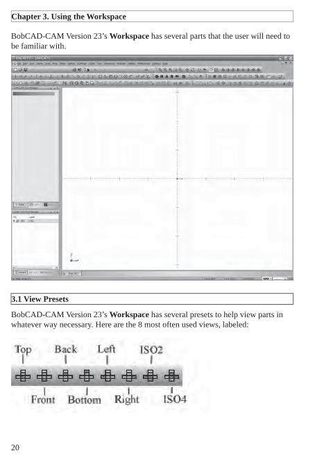
BobCAD-CAM Version 23’s Workspace has several parts that the user will need to be familiar with.
BobCAD-CAM Version 23’s Workspace has several presets to help view parts in whatever way necessary. Here are the 8 most often used views, labeled:
Chapter 3. Using the Workspace
3.1 View Presets

21
Individual settings for the view, including quality, colors, etc., are all listed under the Preferences menu in Settings Part and Settings Default.
BobCAD-CAM Version 23 offers mouse functions that can be used in conjunction with the Shift & Control keys for:
Panning• Dynamic Zoom• Zooming in a Window• Dynamic Rotation• Accessing the Utility Drop-Down Menu• Geometry Selection & Window Picking•
Left Mouse Button•
The Left mouse button is used primarily for selection. The left mouse button also enables other tasks when used in conjunction with other keys on the keyboard.
To select an entity, face, or solid, rest the cursor over the entity or face that is to be selected, and click the left mouse button to select the entity.
SHIFT + Left Mouse Button•
When in selection mode, the left mouse button and shift key on the keyboard combined can be used to chain select geometry in the workspace.
3.2 Mouse Control

22
CTRL + Left Mouse Button•
The control key with the left mouse button is used for Zoom Window mode.
To zoom in on an area: Hold down both the CTRL key and the left mouse button and then drag the cursor over an area of the workspace to zoom in on that area.
Middle Mouse Button and Wheel•
If the mouse has a wheel it can be used as a middle or second mouse button for accessing functionality.
Zooming In: scrolling the wheel toward the front of the mouse will cause the software to zoom in toward the center of the screen.
Zooming Out: scrolling the wheel toward the back of the mouse will cause the software to zoom out away from the center of the screen.
CTRL + Wheel or Middle Mouse Button•
The control key and middle mouse button combined can be used to adjust the vertical and horizontal position of the drawing within the workspace.
Panning: Hold down the CTRL key on the keyboard and the wheel or middle mouse button to freely pan and move the drawing around the workspace.
Right Mouse Button•
The right mouse button is used to access the pop-up menu, indicate that selections are completed, cancel a selection, use verify functions, change views and access the Selection Mask settings. Clicking the right mouse button and choosing Selection Mask from the drop down menu can access the selection mask options. See below for more on this box.
CTRL + Right Mouse Button•
Dynamic Rotation: When holding down the control key on the keyboard and the right mouse button simultaneously, the user is placed in dynamic rotation mode. The user can then move the mouse to rotate the part in the workspace freely.

23
BobCAD-CAM allows the user to have multiple fi les open at the same time. If more than one fi le is open, each one will show up on its own tab at the bottom of the Workspace. To switch between them, click on the tab for each one at the bottom.
In the Window menu, the user has more methods of controlling how parts are displayed. There are 6 parts:
New Window• – this option will create a new tab at the bottom of the Workspace. The new tab is a copy of the existing active drawing.Cascade• – if the user has several drawings open at the same time, the windows displaying the geometry will be reordered to tile on top of each other. The tabs at the bottom will still switch between them.Tile Horizontal• – this will organize multiple drawings in the view stretched out horizontally. This means that the individual drawings will be stacked on top of one another.Tile Vertical• – this will organize multiple drawings in the view stretched out vertically. This means that the individual drawings will be stacked next to one another.Arrange Icons• – if all of the active drawings are minimized within the Workspace and scattered around, this will arrange them in order on the bottom of the view.Active window list• – this section will list all of the drawings that are currently loaded in the Workspace. The active drawing will have a check next to its name.
For most users there will come a time when parts of one drawing will need to be copied into another. To do this:
Highlight the parts of the fi rst drawing to be copied.1. Click on 2. Edit in the main menu and choose Copy, or press CTRL+C to copy the items to the Windows clipboard.Click on the tab of the drawing it has to be copied to at the bottom of the 3. Workspace.Click on 4. Edit in the main menu and choose Paste, or press CTRL+V. The copied parts will appear in the second drawing in the same place they were originally.
Part viewing preferences are set for the currently active drawing by clicking on Preferences and then Settings Part.
3.4 Copying Things from One Drawing to Another
3.3 Multiple File Support in the Workspace
3.5 Setting Part and System View Defaults

24
All settings for viewing the current part are set here. These include background color, new entity color, the highlight color, the quality of the part rendering, etc. Also set here are the current units the part and all operations are done in, whether in inch (SAE), metric, or some other type of unit.
Settings Default has the same box, but the settings there apply to new drawings only. There is also a Directories category not present in Settings Part on the left where the user can set the default folders to retrieve data from and save to.
The Workspace has a few default shortcut keys of its own for part display:
W – toggles wire frame view on and offS – toggles shaded view on & offT – toggles transparency for every solid or surface visible
All layer handling in the software is done through the Layers tab of the Layer-UCS-Post Manager box.
To create a new layer, right-click in the Layer-UCS-Post Manager and choose Add New Layer. Name the new layer whatever is necessary. BobCAD-CAM Version 23 keeps layers separated in the background by their numbers, not their names, so it is possible to name 2 layers the same if required.
To switch to another active layer, click on the Inactive Layer icon for the layer needed. It will change to a check indicating that it’s active. Afterward, all new entities will be drawn on that layer.
To change the layer some existing entities are on, make the layer active fi rst as above. Then, highlight the entities to be moved to the new layer. Right-click in the Workspace and choose Modify to Current Layer. BobCAD-CAM will then place all of the selected entities on the active layer.
3.6 Layer Control

25
To hide and show all entities on a layer, click on the Layer Visible button. When there is a square in the box, the entities on that layer are visible and when there is not, they are hidden.
To toggle between showing and hiding all of the entities on a single layer, simply toggle the Layer Visible button as in the description above. However, to show or hide only a few entities, use the Blank and Unblank icons:
To hide only a few entities:
Click on the 1. Blank icon on the toolbarLeft-click on all of the entities that need to be hidden to select them2. Right-click and choose 3. OK in the pop-up menu.
All of the selected entities will be made invisible.
To show some of those entities again:
Choose the 1. Unblank icon on the toolbar. All of the currently blanked entities will show and BobCAD-CAM will temporarily hide the currently visible parts of the drawingClick on those entities that need to show again to get them highlighted. Right-2. click and choose OK in the pop-up menu. Those entities that were highlighted will be unblanked and the drawing will be returned to normal.
BobCAD-CAM Version 23 allows the user to defi ne the working planes for parts. There are three pre-defi ned planes and the user can create as many others as necessary. When a plane is set active, like layers, all new entities are drawn on that plane. The pre-defi ned planes are the Top (X/Y), Front (X/Z), and Side (Y/Z) planes.
There are several ways to create a new plane. See the Help system for a detailed explanation of all of the methods available.
What follows is an example of using the 3 Points method:
Click on the 1. Point menu, and then on Coordinates. The dialog in the DATA-CAM Tree Manager will display fi elds for the coordinates of the points. 3 points are required.
3.8 Work Planes
3.7 Hiding and Showing Entities

26
Enter in the values in the fi elds. Click 2. OK after each one.
X:0, Y:0, Z:0X:1, Y:0, Z:0X:0, Y:sin(45) Z:cos(45)
Typing in the trigonometric functions will cause BobCAD-CAM to evaluate those functions and change the number in the box to the result of the calculation. It is possible to type in “.7071” in both the Y and Z fi elds, but in reality BobCAD-CAM can support many more decimal places than it may be set to display. Using trigonometric functions such as sin(), cos(), and tan() is much more accurate as BobCAD-CAM will evaluate them as far out as it can, i.e. to 15 decimal places.
Right-click on the 3. UCS tab of the Layer-UCS-Post Manager, and choose Add New UCS.Choose the 3 Point button in the Data-CAM Tree Manager.4. Click the points in the order they were drawn in to create the new work plane. 5. This new plane will be rotated 45 degrees off of the Front plane around the X-axis, because the Y and Z numbers are 45 degrees from (0, 0, 0). It is important to click them in this order because the fi rst point highlighted becomes the origin position (0, 0, 0) of the new work plane, the second becomes the direction of the new +X axis, and the third becomes the new +Y.

28
BobCAD-CAM can draw with wireframes and with solids and surfaces. Generally speaking, wire frames consist of lines, arcs, points, and a few special items like fi llets, gears, and ellipses. Solids have 5 different primitive types: cube, sphere, cone, cylinder, and torus. See the Help system in the software for a full explanation of each of these.
Described in this chapter is an example of a 2 Axis Inside feature, from blank drawing to generating the NC program. The steps described apply to all of the 2 Axis features: 2 Axis Inside, 2 Axis Outside, and 2 Axis Open.
The shape in this example could be used either for a 2 Axis program or for a 4 Axis program with a constant taper all the way around the shape.
Step 1: Begin with an empty drawing by using any one of these 3 methods:
Click on • File in the main menu and then New OR
Click on the • New File icon in the toolbar ORHold the CTRL key down and hit N on the keyboard to start a new • drawing.
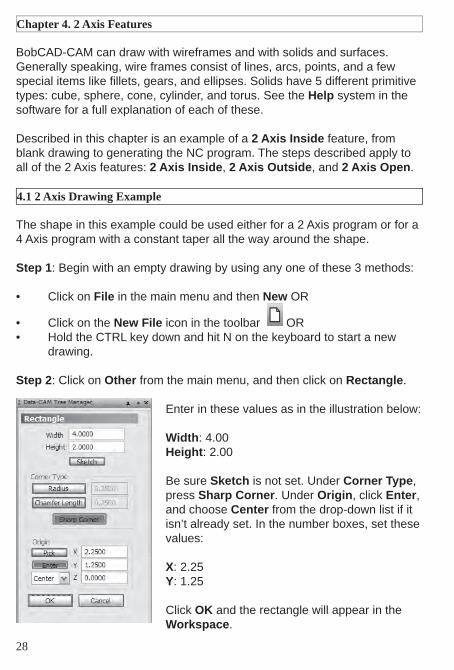
Step 2: Click on Other from the main menu, and then click on Rectangle.
Enter in these values as in the illustration below:
Width: 4.00Height: 2.00
Be sure Sketch is not set. Under Corner Type, press Sharp Corner. Under Origin, click Enter, and choose Center from the drop-down list if it isn’t already set. In the number boxes, set these values:
X: 2.25Y: 1.25
Click OK and the rectangle will appear in the Workspace.
Chapter 4. 2 Axis Features
4.1 2 Axis Drawing Example

29
Step 3: Click on Points in the main menu and then on End. Click near all 4 corners of the rectangle.
Step 4: Choose Arcs from the main menu and then Fillet. In the dialog in the Data-CAM Tree Manager on the left, enter in 10 next to Radius and click OK.
Click on the point on the upper-right corner of the rectangle, then on the point in the upper left. An arc will appear between these two points with a 10 inch radius.
Next, click on the point in the lower right corner, followed by the point in the lower left. Another, identical arc will appear. The drawing should look like the illustration on the next page.

Step 5: Click on Arcs again in the main menu and choose Snap. Set the radius value in the dialog on the left side of the screen to .5”. Set the Start Angle to 0, and the End Angle to 360. This will ensure that BobCAD-CAM draws a full circle.
Click on the upper arc of the drawing near its center. The circle will be drawn at the 90 degree position of this arc. By default, BobCAD-CAM has snap points at 45° intervals along an arc. Since the mouse was clicked closest to the top point on the arc, the circle will be drawn at 90 degrees on it.
The drawing is nearly fi nished and only needs some cleanup to remove parts that are not required.
30
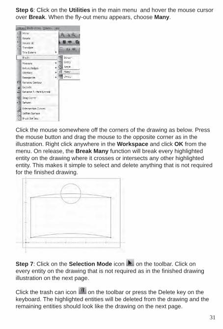
Step 6: Click on the Utilities in the main menu and hover the mouse cursor over Break. When the fl y-out menu appears, choose Many.
Click the mouse somewhere off the corners of the drawing as below. Press the mouse button and drag the mouse to the opposite corner as in the illustration. Right click anywhere in the Workspace and click OK from the menu. On release, the Break Many function will break every highlighted entity on the drawing where it crosses or intersects any other highlighted entity. This makes it simple to select and delete anything that is not required for the fi nished drawing.
Step 7: Click on the Selection Mode icon on the toolbar. Click on every entity on the drawing that is not required as in the fi nished drawing illustration on the next page.
Click the trash can icon on the toolbar or press the Delete key on the keyboard. The highlighted entities will be deleted from the drawing and the remaining entities should look like the drawing on the next page.
31
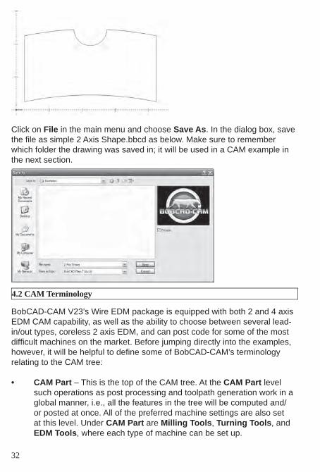
Click on File in the main menu and choose Save As. In the dialog box, save the fi le as simple 2 Axis Shape.bbcd as below. Make sure to remember which folder the drawing was saved in; it will be used in a CAM example in the next section.
BobCAD-CAM V23’s Wire EDM package is equipped with both 2 and 4 axis EDM CAM capability, as well as the ability to choose between several lead-in/out types, coreless 2 axis EDM, and can post code for some of the most diffi cult machines on the market. Before jumping directly into the examples, however, it will be helpful to defi ne some of BobCAD-CAM’s terminology relating to the CAM tree:
CAM Part• – This is the top of the CAM tree. At the CAM Part level such operations as post processing and toolpath generation work in a global manner, i.e., all the features in the tree will be computed and/or posted at once. All of the preferred machine settings are also set at this level. Under CAM Part are Milling Tools, Turning Tools, and EDM Tools, where each type of machine can be set up.
32
4.2 CAM Terminology

Stock• – The Stock is defi ned using a contour and a depth. Once defi ned a transparent solid representing the stock can be displayed.Material – Based on the material type selected, the wire diameter, and the stock thickness the system will automatically calculate the cutting conditions.Feature• – A feature consists of the geometry, single or multiple opera-tions, machining parameters and the toolpath that was calculated using all these attributes.Geometry• – The entities that are being used in the feature. Depend-ing on the operation type these can be points, lines, arcs, splines, contours, etc.Associativity• – Each feature contains all the necessary parameters to calculate tool path, including the geometry stored. This association of the geometry within the feature allows the user to change any of these parameters and compute the tool path again without reselecting or redefi ning all the parameters each time the feature is changed. Operation• – An operation is one element, or task to complete a fea-ture.
Not every feature has all of the same steps. For example, one feature on an EDM part may need several skim passes to maintain accuracy, but another feature on the same part may require only the roughing pass.
Each of these steps is an operation, and together they make up a Composite Operation.
Step 1. Begin by opening the 2 Axis Shape.bbcd fi le saved in section 4.1. If this fi le does not exist, create it fi rst before proceeding with this example so that it will be easier to follow the steps given here.
Step 2. Click on the CAM tab of the Data-CAM Tree Manager. Right click on EDM Stock as shown on the next page.
Hover the mouse cursor over EDM in the menu, and choose 2 Axis Inside. Choosing Inside over Outside designates this part as a die inside the software, and tailors the options available to this feature to those suitable for a die. This example will include only a single feature in order to keep it short, but it is permitted to have multiple features in the same part.
33
4.3 2 Axis CAM Example

Step 3. To assign the geometry on the screen to this feature, right click on Boundary under the new Feature EDM 2X Inside feature that will have been inserted into the tree. Choose Re/Select.
Hold the Shift key on the keyboard and click on the shape. The entire shape should highlight.
34
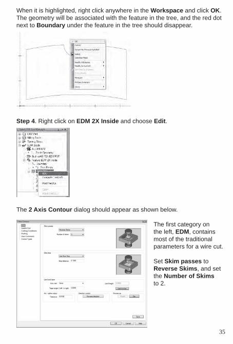
When it is highlighted, right click anywhere in the Workspace and click OK.The geometry will be associated with the feature in the tree, and the red dot next to Boundary under the feature in the tree should disappear.
Step 4. Right click on EDM 2X Inside and choose Edit.
The 2 Axis Contour dialog should appear as shown below.
The fi rst category on the left, EDM, contains most of the traditional parameters for a wire cut.
Set Skim passes to Reverse Skims, and set the Number of Skims to 2.
35

In the Leadin/Out category set the Leadin to Perpendicular Blend. Set the Radius to .125 and the Length to .25. For Leadout, click Same as leadin to copy all of the same values from Leadin.
Set the Start hole’s Diameter to .0625, set the Select point entry to Middle of longest line and leave the rest at default.
In Cutting Conditions, set the Link to database button to have BobCAD-CAM pull all of its conditions from the database associated with this machine. In this way, the user is not required to enter in any conditions by hand.
36
As an aside, for coreless machining, set the Glue stop to Coreless. Coreless is only available on 2 Axis Inside cuts. The help fi les contain a more detailed explanation of all of the available options.

37
In Posting, set the CNC compensation to Off and the Toolpath center to With compensation. With it set this way, BobCAD-CAM will not post the G41/42 cutter compensation codes and will offset the wire path directly from the geometry instead.
In User Comments, the programmer is permitted to insert any special comments that the operator may need to see in the program. As this example isn’t going to be run by an operator, we’ll leave them blank.
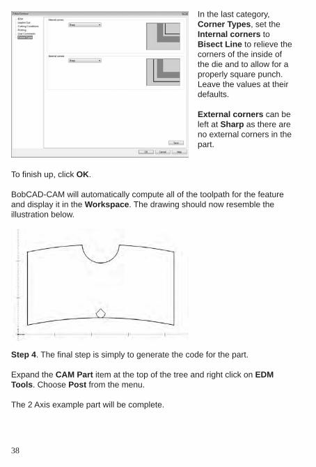
In the last category, Corner Types, set the Internal corners to Bisect Line to relieve the corners of the inside of the die and to allow for a properly square punch. Leave the values at their defaults.
External corners can be left at Sharp as there are no external corners in the part.
To fi nish up, click OK.
BobCAD-CAM will automatically compute all of the toolpath for the feature and display it in the Workspace. The drawing should now resemble the illustration below.
Step 4. The fi nal step is simply to generate the code for the part.
Expand the CAM Part item at the top of the tree and right click on EDM Tools. Choose Post from the menu.
The 2 Axis example part will be complete.
38


40
Chapter 5. 4 Axis Features
BobCAD-CAM can machine parts with wildly varying part topologies. There are 2 examples in this chapter, one having a simple constant taper and one with two completely different shapes to illustrate how to cut parts requiring all 4 independent axes.
A simple 4-axis wire shape in BobCAD-CAM can be as simple as two rect-angles at differing Z heights, as in this example, or more complex as in the example in Section 5.2.
Step 1: Begin with an empty drawing by using any one of these 3 methods:
Click on • File in the main menu and then New OR
Click on the • New File icon in the toolbar ORHold the CTRL key down and hit N on the keyboard to start a new • drawing.
Step 2: Click on Other from the main menu, and then click on Rectangle.Enter in these values as in the illustration below:
Width: 4.00Height: 2.00
Be sure Sketch is not set. Under Corner Type, press Sharp Corner. Under Origin, click Enter, and choose Center from the drop-down list if it isn’t already set. In the number boxes, set these values:
X: 2.25Y: 1.25Z: 0
Click OK and the rectangle will appear in the Workspace.
5.1 4 Axis Taper Example

41
Step 3: Continue in the rectangle function, but change the numbers as below:
Width: 4.5Height: 2.5
Be sure Sketch is not set. Under Corner Type, press Sharp Corner. Under Origin, click Enter, and choose Center from the drop-down list if it isn’t already set. In the number boxes, set these values:
X: 2.25Y: 1.25Z: 2
Click OK and the second rectangle will also appear in the Workspace.

42
This example is designed to follow directly after the drawing example in sec-tion 5.1.
Step 1. Click on the CAM tab in the Data-CAM Tree Manager. Right click on EDM Stock and choose Edit.
In the Stock Settings box that appears, set the Stock Thickness to 2” to correspond to the 2” height intended in the drawing, and set the Upper guide setting to somewhat above that. In this ex-ample, 2.75” is assumed. Click OK on this box.
Step 2. Right click on EDM Stock again and hover the cusor over EDM. From the menu that will fl y out, choose 4 Axis Outside.
A new Feature EDM 4 Axis Outside feature will be inserted in the tree. Under the feature, right click on Boundary and choose Re/Select.
Hold the SHIFT key on the keyboard and click on the bottom line of the inner rectangle somewhere in between the middle of the line and the left corner as shown on the next page. The entire rectangle should highlight. Do the same thing for the outer shape.
5.2 4 Axis Taper CAM Example

43
When both shapes are highlighted, right click anywhere in the Workspace and choose OK from the menu that will appear.
Step 3. Right click on EDM 4X Outside and choose Edit.
A dialog box with a series of option categories on the left will appear.
In the fi rst category, EDM, choose Reverse Skims to cause the machine to reverse direction on the skim passes. Choose 1 for Number of Skims.
Use a .1 distance for Glue stop.

44
In Leadin/Out, set the Leadin to Perpendicular with a Length of .25. For Leadout, use an Arc with a .125 Radius.
Give a .01 Length in Skim pass overlap, and set the Select point en-try to Middle of fi rst.
Under the Cutting Con-ditions category, we’d like BobCAD-CAM to pull the conditions directly from the built-in condi-tions database, so leave all of the parameters at their default values.

The Posting category contains options for com-pensation, overriding the wire speed and tension, and the fl ushing param-eters. We’ll leave these settings at the defaults for this sample.
The last category, User Comments, allows the programmer to insert any special comments that the operator may need to see in the program. As this example isn’t going to be run by an operator, we’ll leave them blank.
Click OK to fi nish setting up the operation. BobCAD-CAM will automatically compute the wire path and display it in the Workspace.
45

46
The computed wire path should look like the illustration below:
If the view is rotated to show the path in 3D and if the stock settings were correct, the path will appear as below:
Step 4. The fi nal step is simply to generate the code for the part.
Expand the CAM Part item at the top of the tree and right click on EDM Tools. Choose Post from the menu.
This 4 Axis part is complete.

The drawing given here is fairly simple; the complexity in this particular ex-ample doesn’t come into play until it is machined. The key is that the entities on the top and bottom shapes are, unlike the previous example, mismatched and will induce a twist in the wire path.
Step 1: Begin with an empty drawing by using any one of these 3 methods:
Click on • File in the main menu and then New OR
Click on the • New File icon in the toolbar ORHold the CTRL key down and hit N on the keyboard to start a new • drawing.
Step 2: Click on Other from the main menu, and then click on Rectangle.Enter in these values as in the illustration below:
Width: 2.0Height: 2.0
Be sure Sketch is not set. Under Corner Type, press Sharp Corner. Under Origin, click Enter, and choose Center from the drop-down list if it isn’t already set. In the number boxes, set these values:
X: 2.0Y: 2.0Z: 0
Click OK and the rectangle will appear in the Workspace as on the next page.
5.3 4 Axis Independent Example
47

Step 3: Click on Arcs in the main menu and then on Coordinates. As shown on the next page, enter these values into the dialog in the Data-CAM Tree Manager:
X: 2Y: 2Z: 2Radius: 2Start Angle: 0End Angle: 360
Step 4: Choose Arcs again from the main menu, then Snap. In the dialog on the left side of the screen again, set the Radius to .5 and leave the Start Angle on 0 and the End Angle on 360 then click OK. This is not strictly necessary, but when the breaking function is used on them it will be easier to select the sections that don’t belong in the fi nal drawing.
Click on the left side of the large circle, and again on the right. The smaller circles will be drawn as the illustration on the next page.
48

Step 5: Click on Utilities in the main menu and hover the mouse cursor over Break. When the fl y-out menu appears, choose Many.
Click the mouse somewhere off the corners of the drawing as shown below. Press the mouse button and drag the mouse to the opposite corner as in the illustration below. Right-click anywhere in the Workspace and click OK in the menu and BobCAD-CAM will break every entity on the drawing where it crosses or intersects any other entity.
This makes it simple to select and delete anything that is not required for the fi nished drawing.
49

Step 6: Click on the Selection Mode icon on the toolbar. Click on every entity on the drawing that is not required for the shape.
Click the trash can icon on the toolbar or press the Delete key on the keyboard. The highlighted entities will be deleted from the drawing and the remaining entities should look like the illustration below.
This example and the one following illustrate fi rst a generic 4 Axis indepen-dent program and then the use of Match Points to correct for mismatched geometry. Note that most 4 Axis geometry will not require the use of match points if the top and bottom shapes match in terms of number of entities. Since the drawing in Chapter 4.3 was deliberately mismatched, these ex-amples will illustrate how to get a good part from bad geometry.
If the user wishes to repeat this fi rst example with the cleaner drawing pro-duced in Chapter 4.2, the toolpath will not require match points to produce a good part.
Step 1. Follow the drawing example in section 5.3 fi rst before proceeding with this example so that it will be easier to follow the steps given here.
50
5.4 4 Axis Independent CAM Example

Step 2. In order for the NC code to be properly posted and the correct cut-ting conditions to be applied to the program, the stock will need to be set up prior to producing the toolpath. The stock used in the EDM portion of the CAM tree will apply to the entire Wire EDM part.
Right click on EDM Stock and choose Edit.
In the box that appears, change the Stock thickness to 2” and adjust the upper guide for the wire slightly above that to 2.75”. Normally in real usage these numbers will need to be accurate, but for the purposes of this example it will serve that the Upper guide simply be above the top of the stock. All stock defi nitions in the EDM portion of the CAM tree begin with the bottom at Z 0.
Click OK at the bottom of the box.
Step 3. Right click on EDM Stock again and hover the cursor over EDM. From the fl y-out menu, click on 4 Axis Inside. A new Feature EDM 4X Inside will be added to the tree.
51

Step 4. Right click on Boundary in the feature and choose Re/Select.
In the Workspace, hold the Shift key down on the keyboard and click on the left side of the square near the top, then do the same in the position shown for the larger shape.
Right click anywhere in the workspace and choose OK and BobCAD-CAM will assign the selected geometry to the feature in the tree.
52

Step 5. Right click on EDM 4X Inside and choose Edit. Fill in each dialog as shown below.
In the fi rst category to the left, EDM, set Skim pass-es to Reverse Skims and set the Number of skims to 3.
Set the Glue stop param-eter to 0.1” in the Stop distance fi eld.
53

For Leadin/Out, set the Leadin to Perpendicular and set the Length to 0.05”.
Set the Leadout to Arc and set its Radius to 0.125”.
Set Diameter in the Start hole section to 0.0625”, and set the Select point entry to Middle of fi rst and leave the rest at default.
In Cutting Conditions, leave Link to database set in order to take advan-tage of BobCAD-CAM’s included cutting conditions fi les.
54

55
In Posting, also leave all of the settings at the defaults. BobCAD-CAM defaults to not offset-ting the wire path, but instead uses the (typi-cally) G41/42 codes on the machine to have the controller take care of the wire offset automatically.
If any optional comments are desired for the indi-vidual operations in the feature, enter them here. These comments are for the machine operator to read, and have no actual effect on the NC program produced except for their presence in the code.
Click OK on the box. BobCAD-CAM will automatically compute the wire path and display it in the Workspace.

As mentioned at the beginning of the example, this wire path is wrong! Keep going; in section 6.4 steps will be taken to correct it.
As seen in this example, BobCAD-CAM does not automatically correct ge-ometry for mismatched 4 axis shapes. The reason for this is that if it were to be automatically corrected, it would be impossible to induce a twist into the shape on purpose.
This example will illustrate how to remove an unintentional twist in the wire path.
The reason for the mismatch and thus the reason for the twist is that the arc on the left side is not infact a single arc, it is split into two parts. This leaves 4 entities on the bottom shape and 5 on the top. There are two ways of fi x-ing this; either correct the arc on the top shape, or use a match point at the desired pivot point on the other shape. This exercise needs to illustrate the second method.
56
5.5 4 Axis Match Point Example

Step 1. Since it will be easier to see now rather than later, this is a good time to add the single match point that will be required for this part. Click on Points in the main menu and choose End.
Click near the upper left corner of the square on the shape and a point will appear there.
57

Step 2. Using match points requires that contour entities be created to use as the geometry for the boundary of the feature. To create contour entities, click on Other in the main menu, followed by Contour.
Start by holding the Shift key down on the keyboard and click near the top of the left side of the square just as was done in Step 1. Also hold Shift and click near the top of the inward arc on the larger shape.
58

59
Right click in the Workspace and choose OK. The contours will appear as large “conic” arrow on the wireframe geometry as shown on the previous page.
Step 3. Re-assign the new contour entities and the match point to the Boundary in the feature.
Right click on Boundary under Feature EDM 4X Inside and choose Re/Select. Click on the geometry in the Workspace as shown here.
Click anywhere on the square fi rst to get it highlighted.Next, click on the larger shape to add it to the selection in the same way. When both shapes are highlighted, click on the match point in the upper left corner of the square. It may be diffi cult to see, so zooming in may help with the selection.
Once the point has been select-ed, right-click in the Workspace and click OK.
Step 4. All that remains is to tell BobCAD-CAM to regenerate the toolpath using the new boundary geometry. Right-click on EDM 4X Inside and choose Compute Toolpath from the menu.

If the selection went well, the result should look like what is shown below:
The match point stops the guide where the point is and allows the other guide a moment to catch up, thus removing any unintentional twist from the part.
Step 5. To generate the 4 Axis NC code, expand the CAM Part item at the top of the tree and right click on EDM Tools. Choose Post from the menu.
The 4 Axis example part will be complete.
60


62
BobCAD-CAM’s Wire EDM package comes with complete, per-machine cutting conditions databases. Each database is stored as a fi le on your hard drive under the BobCAD-CAM installation folder, under EdmTechnology and then EDMCuttingConditions. The fi les can be edited using a database application or peprhaps more easily through the software itself.
To look at the database associated with your machine through the software itself, expand CAM Part at the top of the CAM tree by clicking on the + button to its left fi rst.
Right click on EDM Tools and choose Current Machine.
From the drop-down lists, choose the make and model of your machine and then click OK.
Chapter 6. The Cutting Conditions
6.1 Editing Databases Inside BobCAD-CAM

63
Right click EDM Tools once more and choose Cutting Conditions.
BobCAD-CAM will display the Edit Cutting Conditions Database dialog box. At the top of the box will be listed the current Material, Wire Diameter, and Stock Thickness.
Below that, it is possible to change the Power Setting, Cut Length and Feedrate fi eld for the start of the cut as well as for the rough and skim passes. Choose the Material from the list as well as the Stock Thickness, Wire Diameter, and the Number of Skims to edit. If any of the fi elds below need to be changed, change them and click Save. BobCAD-CAM will update the database fi le for this machine. When fi nished, click Close.

BobCAD-CAM stores the cutting condition in Microsoft Access formatted database fi les. For the most part, they carry the .EDMCC extension with the exception of a few specialized database fi les for use with Sodick machines that are labeled with .SODCC instead.
To edit one of these using an external database editor, fi rst make a copy of the database fi le and rename the fi le extension to .mdb to match the default Access extension.
Open the database fi le with the database software of choice, and choose either the “open” or “connect” option provided in it. Make sure the database type is set to Microsoft Access, and the copied fi le should open easily.
The tables inside it are labeled and the user will fi nd it simple to query the database as if it had been created for any other purpose. When fi nished editing the fi elds, save the database and rename it back to its original extension (either .EDMCC or .SODCC), being careful not to overwrite the original fi le.
To try out the newly edited database, expand CAM Part at the top of the CAM tree by clicking on the + button fi rst.
Right click on EDM Tools and choose Current Machine. Set the make and model to the machine that the conditions database is for.
6.2 Editing Databases Outside BobCAD-CAM
6.3 Changing the Database File
64

Right click EDM Tools once more and choose Current Settings.
Choose the Machine Setup category on the left, then click on CTC Database (Cutting Technology Conditions Database) in the right pane.
Choose the newly edited fi le, then click OK in the dialog.The new database fi le will become associated with this machine until it it is changed by a user at a later date.
65


68
BobCAD-CAM comes equipped with a custom version of Predator™ CNC Editor, widely recognized as the best DNC package available anywhere. When transferring programs to the machine through RS-232 (serial port) links or Ethernet, there simply isn’t a better solution.
BobCAD-CAM uses 2 methods to save fi les to disk.
Post & Save As• – Right-click on the appropriate machine type under CAM Part (Milling Tools, Turning Tools, or EDM Tools) and choose Post & Save As. The software will prompt the user with a Save As dialog.
Save As• from the Layer-UCS-Post Manager – After the program has been posted, right-click in the Layer-UCS-Post Manager where the code is displayed and choose Save As. The Save As dialog will ap-pear.
When the Save As dialog appears, name the fi le, choose the appropriate folder to save to, and press Save.
Chapter 7. Getting Code to the Machine
7.1 Saving Posted Programs

69
The fi le can be saved directly to a fl oppy if desired. If it needs to go to the machine on a CD-ROM, it will be easier to save it to another location and
then burn the CD from there instead of attempting to save the fi le directly to the device.
The Predator™ CNC Editor DNC included with BobCAD-CAM can commu-nicate with a very wide variety of machines. It has quite a few parameters that can be set on a per-machine basis. Check your controller’s manual for the settings preferred by your machine, as the settings must match between both the controller and Predator™.
To set the Predator CNC Editor DNC communication settings, click on DNC and then Properties in the CNC Editor’s main menu.
The system will display a series of 5 dialog boxes:
7.2 Establishing Communication
Communication Settings

1. Select RS-232 Properties – Set the COM port options from here. Most controllers will require that these options be set to match the settings on the machine, but a few rare controls will actually require mismatched settings. See the controller’s documentation to ensure the settings are correct.
2. DNC String and Constant Options – Use this dialog box to set up any special leader or trailer characters the control may require.
70

3. Send Translation Options – Occasionally a rare control will need a char-acter normally output to be changed into something else entirely in order to read the transferred program. Normally no changes will be required; check the controller’s documentation to be sure.
4. Receive Translation Options – Some controllers will send undesired characters back to the computer. This dialog box can be used to either re-move those characters or change them into something else.
71
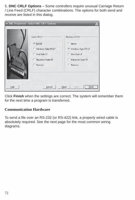
5. DNC CRLF Options – Some controllers require unusual Carriage Return / Line Feed (CRLF) character combinations. The options for both send and receive are listed in this dialog.
Click Finish when the settings are correct. The system will remember them for the next time a program is transferred.
To send a fi le over an RS-232 (or RS-422) link, a properly wired cable isabsolutely required. See the next page for the most common wiringdiagrams.
72
Communication Hardware

These are the common pinouts for nearly all CNC controls.
73

Cables typically need be shorter than 50’ and will need to be shielded to help protect against electromagnetic interference. Take care not to coil a long cable or run any cable around any fl uorescent lighting or near any electrical transformers or power supplies as these will signifi cantly reduce the strength of the signal through the cable, possibly causing communication to fail entirely.
If a good cable is diffi cult to fi nd or to build, or if the machine is more than 50’ from the computer, it is now possible to purchase Predator Grizzly™ cables directly from BobCAD-CAM, Inc. Grizzly™ cables are viable to lengths of up to 400’ in a variety of environments.
The Predator CNC Editor DNC can transfer a program to and from the CNC controller.
Step 1: Open the CNC Editor by either right-click in the Layer-UCS-Post Manager and choose Edit CNC, or click on Modules in the main menu and choose Edit CNC from there.
Step 2: Choose Send to CNC… from the menu
7.3 Transferring by RS-232 (Serial) Link
74
Send a Program to the CNC

75
Step 3: The CNC Editor will automatically begin the transfer. The progress bar near the bottom of the dialog will count off the percentage of the fi le transferred. The progress bar will display 100% when it is complete.
Step 1: To open the CNC Editor, click on Modules in the main menu and choose Edit CNC from there:
Step 2: Choose Receive from CNC… from the DNC menu in the CNC Edi-tor.
Step 3: The CNC Editor will automatically begin the transfer. The large box near the top of the dialog will display the code as it is received. The dialog will disappear when the transfer is complete.
Receive a Program from the CNC
