note: this monitoring checklist does not include changes ... · page 1 of 14 september 2010 note:...
TRANSCRIPT

Petroleum and Natural Gas Monitoring Checklist On-Shore Petroleum and Natural Gas Production 40 CFR 98, subpart W Page 1 of 14 September 2010
Note: This monitoring checklist does not include changes from the 12/23/11 final rule 76 FR 80554 (Technical Revisions and Clarifications to subpart A and subpart W), or corrections from the pending proposed rule, “2012 Technical Corrections, Clarifying and Other Amendments to the Greenhouse Gas Reporting Rule, and Proposed Confidentiality Determinations for Certain Data Elements of the Fluorinated Gas Source Category." EPA is working to update these checklists. Additional information on the subpart W rules can be found at http://www.epa.gov/climatechange/emissions/subpart/w.html. Reporters should refer to the e-CFR for the final rule (http://ecfr.gpoaccess.gov/cgi/t/text/text-idx?c=ecfr&sid=9415fad5f1c7ea4d940d308e1ea74e11&tpl=/ecfrbrowse/Title40/40cfr98_main_02.tpl). Petroleum and Natural Gas Systems Monitoring Checklist for Onshore Petroleum and Natural Gas Production Final Rule: Mandatory Reporting of Greenhouse Gases (40 CFR Part 98) What must be monitored? If emissions are going to flares, need data elements under the source flare stacks.
Record these parameters on an annual basis, unless specified otherwise.
1. Natural Gas Pneumatic Device Venting Actual and estimated counts of high
bleed devices
Concentration of CO2
Actual and estimated counts of low bleed devices
Concentration of CH4
Actual and estimated counts of intermittent bleed devices
2. Natural Gas Driven Pneumatic Pump Venting Count of natural gas driven
pneumatic pumps Concentration of CO2 in produced natural
gas
Concentration of CH4 in produced natural gas
3. Well Venting for Liquids Unloading If Using Calculation Methodology 1:

Petroleum and Natural Gas Monitoring Checklist On-Shore Petroleum and Natural Gas Production 40 CFR 98, subpart W Page 2 of 14 September 2010
For Methodology 1, record these parameters once in two years. Count of wells vented to the atmosphere
for liquids unloading Count of plunger lifts.
Cumulative amount of time of venting from all wells of same tubing diameter and producing horizon/formation combination during the year (hours)
Average flow rate of measured well venting for the recorded time of one representative well venting to the atmosphere under actual conditions for each unique tubing diameter and producing horizon/formation combination during the year (cubic feet per hour of venting)
Average casing diameter (inches) Actual temperature (°F)
Actual pressure (psia) Cumulative number of unloadings vented to the atmosphere
If Using Calculation Methodology 2: Count of wells vented to the atmosphere
for liquids unloading
Count of plunger lifts.
Number of vents per year Casing diameter (inches)
Well depth to first producing horizon (feet) Shut-in pressure (psia)
Time that the well was left open to the atmosphere during unloading (hours)
Average sales flow rate of gas well (cubic feet per hour)
Actual pressure (psia) Actual temperature (°F) Cumulative number of unloadings vented
to the atmosphere
If Using Calculation Methodology 3: Count of wells vented to the atmosphere
for liquids unloading
Count of plunger lifts
Number of vents per year Tubing diameter (inches)
Tubing depth to plunger bumper (feet) Sales-line pressure (psia)
Time that well was left open to the atmosphere during unloading (hours)
Average sales flow rate of the measured well venting (cubic feet per hour)

Petroleum and Natural Gas Monitoring Checklist On-Shore Petroleum and Natural Gas Production 40 CFR 98, subpart W Page 3 of 14 September 2010
Actual pressure (psia) Actual temperature (°F) Cumulative number of unloadings
vented to the atmosphere
4. Gas Well Venting During Completions without Hydraulic Fracturing Average daily gas production rate of all
wells completed during the reporting year (cubic feet/hour)
Total count of completions in calendar year
Cumulative amount of time of all well completions venting (hours)
Actual temperature (°F)
Actual pressure (psia) Vent and flared emissions separately (cubic feet)
Total number of days of gas venting to the atmosphere during backflow for completion
5. Gas Well Venting During Workovers without Hydraulic Fracturing Actual pressure (psia) Actual temperature (°F)
Total count of workovers in calendar
year Vent and flared emissions separately
(cubic feet) Total number of days of gas venting to
the atmosphere during backflow for workover
6. Gas Well Venting During Well Completions with Hydraulic Fracturing For Methodologies 1 & 2, record these parameters once in two years.
Cumulative amount of time of all well completion venting in a field during the year (hours)
Average flow rate of the measured well completion venting under actual conditions converted to standard conditions (cubic feet per hour)
Number of completions employing reduced emissions completions and engineering estimate based on best available data of the amount of gas recovered to sales
Total count of completions in Calendar Year

Petroleum and Natural Gas Monitoring Checklist On-Shore Petroleum and Natural Gas Production 40 CFR 98, subpart W Page 4 of 14 September 2010
Actual pressure (psia) Actual temperature (°F) Vent and flared emissions separately
at standard conditions (cubic feet) Volume of CO2 or N2 injected gas at
standard conditions that was injected into the reservoir during an energized fracture job (cubic feet)
Volume of natural gas at standard conditions that was recovered into a sales pipeline (cubic feet)
Total number of days of gas venting to the atmosphere during backflow for completion
If Using Calculation Methodology 1: Average flow rate of venting to
atmosphere or routing to flare by recording flow meter (cubic feet per hour)
If Using Calculation Methodology 2: Average flow rate under
subsonic/sonic flow conditions (cubic feet per hour)
Actual pressure (psia)
Cross sectional area of orifice (m2) Upstream temperature (K)
Upstream pressure (psia) Downstream pressure (psia)
7. Gas Well Venting During Well Workovers with Hydraulic Fracturing For Methodologies 1 & 2, record these parameters once in two years.
Cumulative amount of time of all well workover venting in a field during the year (hours)
Average flow rate of the measured well workover venting under actual conditions converted to standard conditions (cubic feet per hour)
Number of workovers employing reduced emissions completions and engineering estimate based on best available data of the amount of gas recovered to sales
Total count of workovers in calendar year
Actual pressure (psia) Actual temperature (°F) Vent and flared emissions separately
at standard conditions (cubic feet) Volume of CO2 or N2 injected gas at
standard conditions that was injected into the reservoir during an energized fracture

Petroleum and Natural Gas Monitoring Checklist On-Shore Petroleum and Natural Gas Production 40 CFR 98, subpart W Page 5 of 14 September 2010
job (cubic feet) Volume of natural gas at standard
conditions that was recovered into a sales pipeline (cubic feet)
Total number of days of gas venting to the atmosphere during backflow for workovers
If Using Calculation Methodology 1: Average flow rate of venting to
atmosphere or routing to flare by recording flow meter (cubic feet per hour)
If Using Calculation Methodology 2: Average flow rate under
subsonic/sonic flow conditions (cubic feet per hour)
Actual pressure (psia)
Cross sectional area of orifice (m2) Upstream temperature (K)
Upstream pressure (psia) Downstream pressure (psia)
8. Flare Stack Emissions Continuous flow monitor on flare
(Y/N) Continuous gas analyzer on the gas to the
flare (Y/N)
Volume of gas sent to flare annually (cubic feet)
Percent of gas sent to un-lit flare
Flare combustion efficiency (98% if manufacturer data not available)
Mole fraction of CO2 in gas to the flare
Mole fraction of gas hydrocarbon constituents (such as methane, ethane, propane, butane, and pentanes-plus)
Actual Process Temperature (°F)
Actual Process Pressure (psia) 9. Storage Tanks Emissions Storage tank receiving separator oil
have a vapor recovery system (Y/N)
Count of wellhead separators that dump valve factor is applied to, if well head gas-liquid separator liquid dump valve is not functioning properly during the calendar year

Petroleum and Natural Gas Monitoring Checklist On-Shore Petroleum and Natural Gas Production 40 CFR 98, subpart W Page 6 of 14 September 2010
Total time well head gas-liquid
separator liquid dump valve is not closing properly in the calendar year (hours)
Percent of gas sent to un-lit flare
If Using Calculation Methodology 1:
Range of concentrations of flash gas, for CH4 and CO2
Sales oil or stabilized oil production rate (barrels per day)
Average separator temperature (°F) Ambient air temperature (°F)
Average separator pressure (psig) Ambient air pressure (psig)
Average sales oil or stabilized oil API gravity (°)
Separator oil composition and Reid vapor pressure
Number of wellhead separators sending oil to atmospheric tanks
Count of hydrocarbon tanks at well pads
Best estimate of count of stock tanks not at well pads receiving oil
Total volume of oil from all wellhead separators sent to tank(s) annually (barrels)
Count of tanks with emissions control measures, either vapor recovery system or flaring, for tanks at well pads
Best estimate of count of stock tanks assumed to have emissions control measures not at well pads, receiving oil
If Using Calculation Methodology 2: Number of wellhead separators
sending oil to atmospheric tanks
Separator temperature (°F)
Separator pressure (psig) Sales oil or stabilized oil API gravity (°)
Count of hydrocarbon tanks at well pads
Total volume of oil from all wellhead separators sent to tank(s) annually (barrels)
Best estimate of count of stock tanks not at well pads receiving oil
Count of tanks with emissions control measures, either vapor recovery system or flaring, for tanks at well pads
Best estimate of count of stock tanks assumed to have emissions control measures not at well pads, receiving
Range of concentrations of flash gas, for CH4 and CO2

Petroleum and Natural Gas Monitoring Checklist On-Shore Petroleum and Natural Gas Production 40 CFR 98, subpart W Page 7 of 14 September 2010
oil
Separator oil composition at separator pressure and temperature (for the assumption that all of the CH4 and CO2 in solution in the separator oil is emitted)
If Using Calculation Methodology 3: Total volume of sales oil from all
wells annually (barrels)
Total number of wells sending oil directly to tanks
Total number of wells sending oil to separators off the well pads
Sales oil API gravity range for wells sending oil directly to tanks and for wells sending oils to separators off the well pads (°)
Count of hydrocarbon tanks on wellpads
Count of hydrocarbon tanks, both on and off well pads assumed to have emissions control measures: either vapor recovery system or flaring of tank vapors
Produced oil and gas compositions (for the assumption that all of the CH4 and CO2 in both oil and gas are emitted from the tank)
If Using Calculation Methodology 4: Total volume of sales oil from all
wells annually (barrels) Total number of wells sending oil directly to
tanks Total number of wells sending oil to
separators off the well pads Sales oil API gravity range for wells sending
oil directly to tanks and for wells sending oils to separators off the well pads (°)
Count of hydrocarbon tanks on wellpads
Count of hydrocarbon tanks, both on and off well pads assumed to have emissions control measures: either vapor recovery system or flaring of tank vapors
Well production oil and gas compositions (for the assumption that all of the CH4 and CO2 in the oil are emitted from the tank)
If Using Calculation Methodology 5: Number of wellhead separators Number of wells without wellhead

Petroleum and Natural Gas Monitoring Checklist On-Shore Petroleum and Natural Gas Production 40 CFR 98, subpart W Page 8 of 14 September 2010
separators Total volume of oil production
annually (barrels) Best estimate of fraction of production sent
to tanks with assumed control measures: either vapor recovery system or flaring of tank vapors
Count of hydrocarbon tanks on well pads
10. Reciprocating Compressor Rod Packing Venting Count of compressors
Actual Process Temperature (°F)
Actual Process Pressure (psia)
11. Well Testing Venting and Flaring Average gas –to-oil ratio (GOR) of
the hydrocarbon production from each well tested (cubic feet of gas per barrel of oil)
Flow rate for the well being tested (barrels of oil per day)
Duration of the well test (number of days during the year)
Number of wells tested per basin in calendar year
Actual Process Pressure (psia) Actual Process Temperature (°F)
Venting gas emissions
12. Associated Gas Venting and Flaring GOR of the hydrocarbon
production from each well whose associated natural gas is vented or flared (cubic feet of gas per barrel of oil)
Volume of oil produced in the calendar year during which associated gas was vented or flared (barrels)
Number of wells venting or flaring associated natural gas in calendar year
Actual Process Temperature (°F)
Actual Process Pressure (psia) Flaring gas emissions

Petroleum and Natural Gas Monitoring Checklist On-Shore Petroleum and Natural Gas Production 40 CFR 98, subpart W Page 9 of 14 September 2010
13. Dehydrator Vents For glycol dehydrator with a throughput greater than or equal to 0.4 million cubic feet per day: Feed natural gas flow rate
(million standard cubic feet per day)
Feed natural gas water content
Outlet natural gas water content Absorbent circulation pump type (natural gas pneumatic/air pneumatic/ electric)
Absorbent circulation rate Absorbent type (TEG/DEG/EG)
Use of stripping natural gas (Y/N) Use of flash tank separator (Y/N)
Total time of operation (hours) Wet natural gas temperature (°F)
Wet natural gas composition Wet natural gas pressure (psig)
Concentration of CH4 in natural gas
Concentration of CO2 in natural gas
Vent gas controls used
Vent and flared emissions separately (cubic feet)
For glycol dehydrator with a throughput less than to 0.4 million standard cubic feet per year: Count of glycol dehydrators Vent gas controls used
Vent emissions (cubic feet)
For absorbent desiccant dehydrators: Count of desiccant dehydrators
Vent gas controls used
Time between refilling (days) Pressure of the gas (psia)
Height of the dehydrator vessel (ft)
Inside diameter of the vessel (ft)
Percent of packed vessel volume that is gas
14. EOR Injection Pump Blowdown

Petroleum and Natural Gas Monitoring Checklist On-Shore Petroleum and Natural Gas Production 40 CFR 98, subpart W Page 10 of 14 September 2010
Total volume of blowdown
equipment chambers between isolation valves (cubic feet)
Number of blowdowns per calendar year
Density of critical phase EOR injection gas (kg/ft3)
Mass fraction of GHG in critical phase injection gas
Pump capacity (barrels per day)
15. Acid Gas Removal (AGR) Vents If using Calculation Methodology 1: Total throughput into the AGR
unit and/or total throughput out of the AGR unit (cubic feet per year)
Volume fraction of CO2 content in the vent from the AGR unit
Emissions recovered and transferred outside the facility
If using Calculation Methodology 2: Total throughput out of the AGR
unit at actual conditions (cubic feet)
Volume fraction of CO2 content in vent gas from the AGR unit
Emissions recovered and transferred outside the facility
If using Calculation Methodology 3: Total throughput through the
AGR unit at actual conditions (cubic feet)
Volume fraction of CO2 content in natural gas into the AGR unit
Volume fraction of CO2 content in natural gas out of the AGR unit
Actual pressure (psia)
Actual Temperature (°F )
Emissions recovered and transferred outside the facility
If using Calculation Methodology 4: Natural gas feed temperature
Natural gas feed pressure

Petroleum and Natural Gas Monitoring Checklist On-Shore Petroleum and Natural Gas Production 40 CFR 98, subpart W Page 11 of 14 September 2010
Natural gas flow rate Acid gas content of feed natural gas
Unit operating hours, excluding downtime for maintenance or standby
Acid gas content of outlet natural gas
Solvent pressure Exit temperature of natural gas
Solvent circulation rate Solvent temperature
Solvent weight
16. EOR Hydrocarbon Liquids Dissolved CO2 Volume of crude oil produced
annually (barrels) Amount of CO2 retained in hydrocarbon
liquids at STP conditions (metric tons per barrel)
17. Centrifugal Compressor Wet Seal Degassing Venting Total number of centrifugal
compressors
18. Valves Concentration of CH4 in produced
natural gas Concentration of CO2 in produced natural
gas Report CO2 emissions from all
valves (standard cubic feet) Report CH4 emissions from all valves
(standard cubic feet) Operating time of leaking
component (hours) Total number of components found leaking
19. Connectors Concentration of CH4 in produced
natural gas Concentration of CO2 in produced natural
gas Report CO2 emissions from all
connectors (standard cubic feet) Report CH4 emissions from all connectors
(standard cubic feet) Operating time of leaking
component (hours) Total number of components found leaking
20. Open Ended Lines Concentration of CH4 in produced Concentration of CO2 in produced natural

Petroleum and Natural Gas Monitoring Checklist On-Shore Petroleum and Natural Gas Production 40 CFR 98, subpart W Page 12 of 14 September 2010
natural gas gas Report CO2 emissions from all
open ended lines (standard cubic feet)
Report CH4 emissions from all open ended lines (standard cubic feet)
Operating time of leaking component (hours)
Total number of components found leaking
21. Pressure Relief Valves Concentration of CH4 in produced
natural gas Concentration of CO2 in produced natural
gas Report CO2 emissions from all
pressure relief valves (standard cubic feet)
Report CH4 emissions from all pressure relief valves (standard cubic feet)
Operating time of leaking component (hours)
Total number of components found leaking
22. Pumps Concentration of CH4 in produced
natural gas Concentration of CO2 in produced natural
gas Report CO2 emissions from all
pumps (standard cubic feet) Report CH4 emissions from all pumps
(standard cubic feet) Operating time of leaking
component (hours) Total number of components found leaking
23. Flanges Concentration of CH4 in produced
natural gas Concentration of CO2 in produced natural
gas Report CO2 emissions from all
flanges (standard cubic feet) Report CH4 emissions from all flanges
(standard cubic feet) Operating time of leaking
component (hours) Total number of components found leaking
24. Instruments Concentration of CH4 in produced
natural gas Concentration of CO2 in produced natural
gas Report CO2 emissions from all
instruments (standard cubic feet) Report CH4 emissions from all instruments
(standard cubic feet) Operating time of leaking
component (hours) Total number of components found leaking
25. Loading Arms Concentration of CH4 in produced Concentration of CO2 in produced natural

Petroleum and Natural Gas Monitoring Checklist On-Shore Petroleum and Natural Gas Production 40 CFR 98, subpart W Page 13 of 14 September 2010
natural gas gas Report CO2 emissions from all
loading arms (standard cubic feet) Report CH4 emissions from all loading
arms (standard cubic feet) Operating time of leaking
component (hours) Total number of components found leaking
26. Stuffing Boxes Concentration of CH4 in produced
natural gas Concentration of CO2 in produced natural
gas Report CO2 emissions from all
stuffing boxes (standard cubic feet)
Report CH4 emissions from all stuffing boxes (standard cubic feet)
Operating time of leaking component (hours)
Total number of components found leaking
27. Compressor Seals Concentration of CH4 in produced
natural gas Concentration of CO2 in produced natural
gas Report CO2 emissions from all
compressor seals (standard cubic feet)
Report CH4 emissions from all compressor seals (standard cubic feet)
Operating time of leaking component (hours)
Total number of components found leaking
28. Dump Lever Arms Concentration of CH4 in produced
natural gas Concentration of CO2 in produced natural
gas Report CO2 emissions from all
dump lever arms (standard cubic feet)
Report CH4 emissions from all dump lever arms (standard cubic feet)
Operating time of leaking component (hours)
Total number of components found leaking
29. Breather Caps Concentration of CH4 in produced
natural gas Concentration of CO2 in produced natural
gas Report CO2 emissions from all
breather caps (standard cubic feet) Report CH4 emissions from all breather
caps (standard cubic feet) Operating time of leaking
component (hours) Total number of components found leaking
30. Stationary or Portable Fuel Combustion Emissions

Petroleum and Natural Gas Monitoring Checklist On-Shore Petroleum and Natural Gas Production 40 CFR 98, subpart W Page 14 of 14 September 2010
Cumulative number of external
fuel combustion units with a rated heat capacity equal to or less than 5 MMBtu/hr, by type of unit
Cumulative number of external fuel combustion units with a rated heat capacity larger than 5 MMBtu/hr, by type of unit
Cumulative emissions from external fuel combustion units with a rated heat capacity larger than 5 MMBtu/hr, by type of unit (cubic feet)
Cumulative volume of fuel combusted in external fuel combustion units with a rated heat capacity larger than 5 MMBtu/hr, by fuel type (cubic feet)
Cumulative number of all internal combustion units, by type of units
Cumulative emissions from internal combustion units, by type of unit (cubic feet)
Cumulative mass/volume of fuel combusted in internal combustion units, by fuel type
Concentration of gas hydrocarbon constituents (such as methane, ethane, propane, butane and pentanes plus)
Petroleum and Natural Gas Monitoring Checklist On-Shore Natural Gas Processing 40 CFR 98, subpart W Page 1 of 8 November 2010
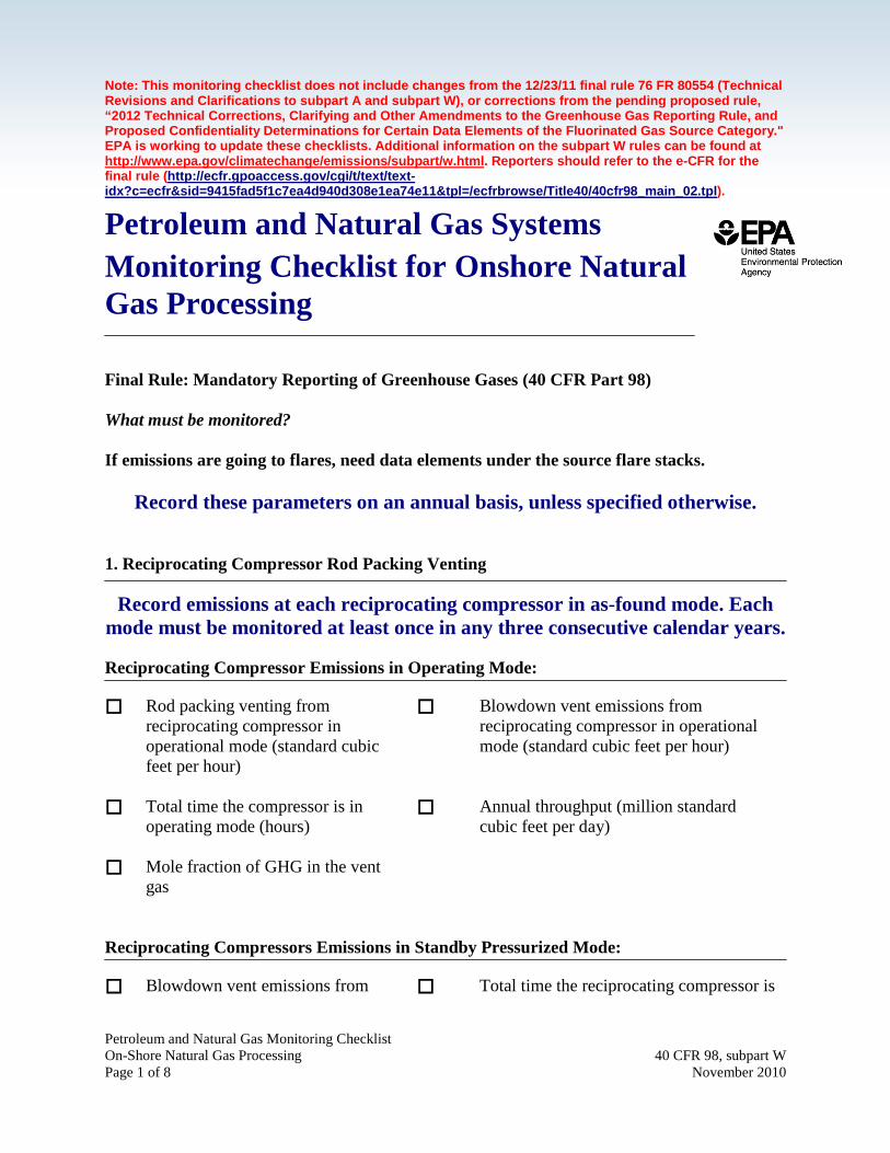
Note: This monitoring checklist does not include changes from the 12/23/11 final rule 76 FR 80554 (Technical Revisions and Clarifications to subpart A and subpart W), or corrections from the pending proposed rule, “2012 Technical Corrections, Clarifying and Other Amendments to the Greenhouse Gas Reporting Rule, and Proposed Confidentiality Determinations for Certain Data Elements of the Fluorinated Gas Source Category." EPA is working to update these checklists. Additional information on the subpart W rules can be found at http://www.epa.gov/climatechange/emissions/subpart/w.html. Reporters should refer to the e-CFR for the final rule (http://ecfr.gpoaccess.gov/cgi/t/text/text-idx?c=ecfr&sid=9415fad5f1c7ea4d940d308e1ea74e11&tpl=/ecfrbrowse/Title40/40cfr98_main_02.tpl). Petroleum and Natural Gas Systems Monitoring Checklist for Onshore Natural Gas Processing Final Rule: Mandatory Reporting of Greenhouse Gases (40 CFR Part 98) What must be monitored? If emissions are going to flares, need data elements under the source flare stacks.
Record these parameters on an annual basis, unless specified otherwise. 1. Reciprocating Compressor Rod Packing Venting
Record emissions at each reciprocating compressor in as-found mode. Each mode must be monitored at least once in any three consecutive calendar years. Reciprocating Compressor Emissions in Operating Mode: Rod packing venting from
reciprocating compressor in operational mode (standard cubic feet per hour)
Blowdown vent emissions from reciprocating compressor in operational mode (standard cubic feet per hour)
Total time the compressor is in operating mode (hours)
Annual throughput (million standard cubic feet per day)
Mole fraction of GHG in the vent gas
Reciprocating Compressors Emissions in Standby Pressurized Mode: Blowdown vent emissions from Total time the reciprocating compressor is

Petroleum and Natural Gas Monitoring Checklist On-Shore Natural Gas Processing 40 CFR 98, subpart W Page 2 of 8 November 2010
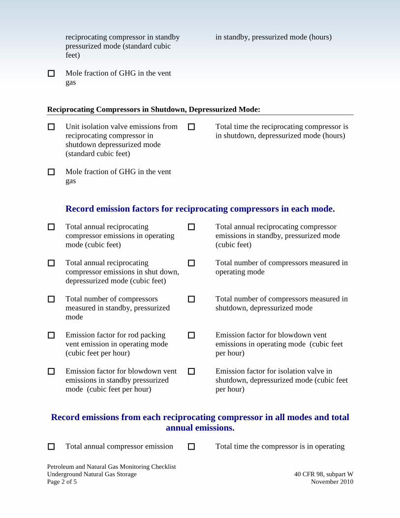
reciprocating compressor in standby pressurized mode (standard cubic feet)
in standby, pressurized mode (hours)
Mole fraction of GHG in the vent gas
Reciprocating Compressors in Shutdown, Depressurized Mode: Unit isolation valve emissions from
reciprocating compressor in shutdown depressurized mode (standard cubic feet)
Total time the reciprocating compressor is in shutdown, depressurized mode (hours)
Mole fraction of GHG in the vent gas
Record emission factors for reciprocating compressors in each mode.
Total annual reciprocating
compressor emissions in operating mode (cubic feet)
Total annual reciprocating compressor emissions in standby, pressurized mode (cubic feet)
Total annual reciprocating compressor emissions in shut down, depressurized mode (cubic feet)
Total number of compressors measured in operating mode
Total number of compressors measured in standby, pressurized mode
Total number of compressors measured in shutdown, depressurized mode
Emission factor for rod packing vent emission in operating mode (cubic feet per hour)
Emission factor for blowdown vent emissions in operating mode (cubic feet per hour)
Emission factor for blowdown vent emissions in standby pressurized mode (cubic feet per hour)
Emission factor for isolation valve in shutdown, depressurized mode (cubic feet per hour)
Record emissions from each reciprocating compressor in all modes and total
annual emissions. Concentration of CH4 in Concentration of CO2 in produced/feed

Petroleum and Natural Gas Monitoring Checklist On-Shore Natural Gas Processing 40 CFR 98, subpart W Page 3 of 8 November 2010
produced/feed natural gas for reciprocating compressor in onshore natural gas processing facilities
natural gas for reciprocating compressor in onshore natural gas processing facilities
Total time the reciprocating compressor is in standby, pressurized mode in reporting year (hours)
Total time the reciprocating compressor is in shutdown, depressurized mode in reporting year (hours)
Total annual compressor emission from all modes of operation (standard cubic feet)
Total time the compressor is in operating mode in reporting year (hours)
2. Centrifugal Compressor Wet Seal Degassing Venting
Record emissions at each centrifugal compressor in as-found mode. Each
mode must be monitored at least once in any three consecutive calendar years. Centrifugal Compressor Emissions in Operating Mode: Wet seal oil degassing vents
emissions from centrifugal compressor in operational mode (standard cubic feet per hour)
Blowdown vent emissions centrifugal compressor in operational mode (standard cubic feet per hour)
Total time the centrifugal compressor is in operating mode (hours)
Number of wet seals connected to the degassing vent
Type of meters used for making measurements
Fraction of operating time wet seal degassing vent gas is sent to vapor recovery or fuel gas
Mole fraction of GHG in the vent gas
Annual throughput (million standard cubic feet per day)
Centrifugal Compressors in Not-operating, Depressurized Mode: Unit isolation valve emissions from
centrifugal compressor in shutdown depressurized mode (standard cubic feet)
Total time the centrifugal compressor is in shutdown, depressurized mode (hours)
Mole fraction of GHG in the vent gas

Petroleum and Natural Gas Monitoring Checklist On-Shore Natural Gas Processing 40 CFR 98, subpart W Page 4 of 8 November 2010
Record emission factors for centrifugal compressors in each mode. Total annual emissions from all
centrifugal compressor in operating mode (cubic feet)
Total annual emissions from all centrifugal compressor in shut down, depressurized mode (cubic feet)
Total number of centrifugal compressors measured in operating mode
Total number of centrifugal compressors measured in shutdown, depressurized mode
Emission factor for wet seal degassing vent in operating mode (cubic feet per hour)
Emission factor for blowdown vent emissions in operating mode (cubic feet per hour)
Emission factor for isolation valve in shutdown, depressurized mode (cubic feet per hour)
Record emissions from each centrifugal compressor in all modes and total
annual emissions. Concentration of CH4 in
produced/feed natural gas for centrifugal compressor in onshore natural gas processing facilities
Concentration of CO2 in produced/feed natural gas for centrifugal compressor in onshore natural gas processing facilities
Total time the centrifugal compressor is in shutdown, depressurized mode in reporting year (hours)
Total annual centrifugal compressor emission from all modes of operation (standard cubic feet)
Total time the centrifugal compressor is in operating mode in reporting year (hours)
3. Blowdown Vents Number of repetitive blowdowns
for each equipment type of a unique volume
Total volume of blowdown equipment chambers (including pipelines, compressors and vessels) between isolation valves (cubic feet)
Actual temperature in the blowdown equipment chamber
Actual pressure in the blowdown equipment chamber (psia)

Petroleum and Natural Gas Monitoring Checklist On-Shore Natural Gas Processing 40 CFR 98, subpart W Page 5 of 8 November 2010
(°F) Emissions per equipment type
(cubic feet)
4. Dehydrator Vents For glycol dehydrator with a throughput greater than or equal to 0.4 million cubic feet per day: Feed natural gas flow rate
(million standard cubic feet per day)
Feed natural gas water content
Outlet natural gas water content Absorbent circulation pump type (natural gas pneumatic/air pneumatic/ electric)
Absorbent circulation rate Absorbent type (TEG/DEG/EG)
Use of stripping natural gas (Y/N) Use of flash tank separator (Y/N)
Total time of operation (hours) Wet natural gas temperature (°F)
Wet natural gas composition Wet natural gas pressure (psig)
Concentration of CH4 in natural gas
Concentration of CO2 in natural gas
Vent gas controls used
For glycol dehydrator with a throughput less than to 0.4 million standard cubic feet per year: Count of glycol dehydrators Vent gas controls used
For absorbent desiccant dehydrators: Count of desiccant dehydrators
Vent gas controls used
Time between refilling (days) Pressure of the gas (psia)
Height of the dehydrator vessel (ft)
Inside diameter of the vessel (ft)

Petroleum and Natural Gas Monitoring Checklist On-Shore Natural Gas Processing 40 CFR 98, subpart W Page 6 of 8 November 2010
Percent of packed vessel volume that is gas
5. Acid Gas Removal (AGR) Vent Stacks If using Calculation Methodology 1: Total throughput into the AGR
unit and/or total throughput out of the AGR unit (cubic feet per year)
Volume fraction of CO2 content in the vent from the AGR unit
Emissions recovered and transferred outside the facility (cubic feet)
If using Calculation Methodology 2: Total throughput flowing out of
the AGR unit at actual conditions (cubic feet)
Volume fraction of CO2 content in vent gas from the AGR unit
Emissions recovered and transferred outside the facility (cubic feet)
If using Calculation Methodology 3: Total throughput through the
AGR unit at actual conditions (cubic feet)
Volume fraction of CO2 content in natural gas into the AGR unit
Volume fraction of CO2 content in natural gas out of the AGR unit
Actual pressure (psia)
Actual Temperature (°F )
Emissions recovered and transferred outside the facility (cubic feet)
If using Calculation Methodology 4: Natural gas feed temperature
Natural gas feed pressure
Natural gas flow rate Acid gas content of feed natural gas
Unit operating hours, excluding downtime for maintenance or standby
Acid gas content of outlet natural gas

Petroleum and Natural Gas Monitoring Checklist On-Shore Natural Gas Processing 40 CFR 98, subpart W Page 7 of 8 November 2010
Solvent pressure Exit temperature of natural gas
Solvent circulation rate Solvent temperature
Solvent weight
6. Flare Stack Emissions Continuous flow monitor on flare
(Y/N) Continuous gas analyzer on the gas to the
flare (Y/N)
Volume of gas sent to flare annually (cubic feet)
Percent of gas sent to un-lit flare
Flare combustion efficiency (98% if manufacturer data not available)
Mole fraction of CO2 in gas to the flare
Mole fraction of gas hydrocarbon constituents (such as methane, ethane, propane, butane, and pentanes-plus)
Actual Process Temperature (°F)
Actual Process Pressure (psia) 7. Valves Concentration of CH4 in feed
natural gas Concentration of CO2 in feed natural gas
Report CO2 emissions from all valves (standard cubic feet)
Report CH4 emissions from all valves (standard cubic feet)
Operating time of leaking component (hours)
Total number of components found leaking
8. Connectors Concentration of CH4 in feed
natural gas Concentration of CO2 in feed natural gas
Report CO2 emissions from all connectors (standard cubic feet)
Report CH4 emissions from all connectors (standard cubic feet)
Operating time of leaking component (hours)
Total number of components found leaking

Petroleum and Natural Gas Monitoring Checklist On-Shore Natural Gas Processing 40 CFR 98, subpart W Page 8 of 8 November 2010
9. Open Ended Lines Concentration of CH4 in feed
natural gas Concentration of CO2 in feed natural gas
Report CO2 emissions from all open ended lines (standard cubic feet)
Report CH4 emissions from all open ended lines (standard cubic feet)
Operating time of leaking component (hours)
Total number of components found leaking
10. Pressure Relief Valves Concentration of CH4 in feed
natural gas Concentration of CO2 in feed natural gas
Report CO2 emissions from all pressure relief valves (standard cubic feet)
Report CH4 emissions from all pressure relief valves (standard cubic feet)
Operating time of leaking component (hours)
Total number of components found leaking
11. Meters Concentration of CH4 in feed
natural gas Concentration of CO2 in feed natural gas
Report CO2 emissions from all meters (standard cubic feet)
Report CH4 emissions from all meters (standard cubic feet)
Operating time of leaking component (hours)
Total number of components found leaking
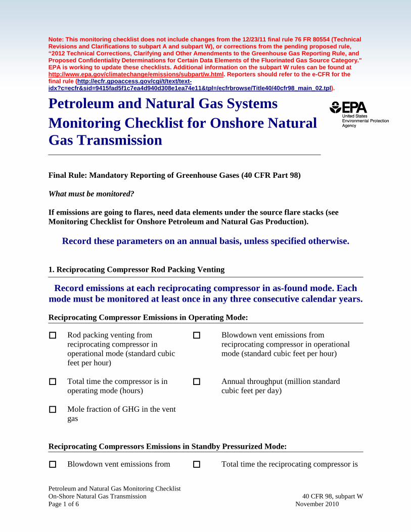
Petroleum and Natural Gas Monitoring Checklist On-Shore Natural Gas Transmission 40 CFR 98, subpart W Page 1 of 6 November 2010
Note: This monitoring checklist does not include changes from the 12/23/11 final rule 76 FR 80554 (Technical Revisions and Clarifications to subpart A and subpart W), or corrections from the pending proposed rule, “2012 Technical Corrections, Clarifying and Other Amendments to the Greenhouse Gas Reporting Rule, and Proposed Confidentiality Determinations for Certain Data Elements of the Fluorinated Gas Source Category." EPA is working to update these checklists. Additional information on the subpart W rules can be found at http://www.epa.gov/climatechange/emissions/subpart/w.html. Reporters should refer to the e-CFR for the final rule (http://ecfr.gpoaccess.gov/cgi/t/text/text-idx?c=ecfr&sid=9415fad5f1c7ea4d940d308e1ea74e11&tpl=/ecfrbrowse/Title40/40cfr98_main_02.tpl). Petroleum and Natural Gas Systems Monitoring Checklist for Onshore Natural Gas Transmission Final Rule: Mandatory Reporting of Greenhouse Gases (40 CFR Part 98) What must be monitored? If emissions are going to flares, need data elements under the source flare stacks (see Monitoring Checklist for Onshore Petroleum and Natural Gas Production).
Record these parameters on an annual basis, unless specified otherwise. 1. Reciprocating Compressor Rod Packing Venting
Record emissions at each reciprocating compressor in as-found mode. Each mode must be monitored at least once in any three consecutive calendar years. Reciprocating Compressor Emissions in Operating Mode: Rod packing venting from
reciprocating compressor in operational mode (standard cubic feet per hour)
Blowdown vent emissions from reciprocating compressor in operational mode (standard cubic feet per hour)
Total time the compressor is in operating mode (hours)
Annual throughput (million standard cubic feet per day)
Mole fraction of GHG in the vent gas
Reciprocating Compressors Emissions in Standby Pressurized Mode: Blowdown vent emissions from Total time the reciprocating compressor is

Petroleum and Natural Gas Monitoring Checklist On-Shore Natural Gas Transmission 40 CFR 98, subpart W Page 2 of 6 November 2010
reciprocating compressor in standby pressurized mode (standard cubic feet)
in standby, pressurized mode (hours)
Mole fraction of GHG in the vent gas
Reciprocating Compressors in Shutdown, Depressurized Mode: Unit isolation valve emissions from
reciprocating compressor in shutdown depressurized mode (standard cubic feet)
Total time the reciprocating compressor is in shutdown, depressurized mode (hours)
Mole fraction of GHG in the vent gas
Record emission factors for reciprocating compressors in each mode.
Total annual reciprocating
compressor emissions in operating mode (cubic feet)
Total annual reciprocating compressor emissions in standby, pressurized mode (cubic feet)
Total annual reciprocating compressor emissions in shut down, depressurized mode (cubic feet)
Total number of compressors measured in operating mode
Total number of compressors measured in standby, pressurized mode
Total number of compressors measured in shutdown, depressurized mode
Emission factor for rod packing vent emission in operating mode (cubic feet per hour)
Emission factor for blowdown vent emissions in operating mode (cubic feet per hour)
Emission factor for blowdown vent emissions in standby pressurized mode (cubic feet per hour)
Emission factor for isolation valve in shutdown, depressurized mode (cubic feet per hour)
Record emissions from each reciprocating compressor in all modes and total
annual emissions. Total annual compressor emission
from all modes of operation Total time the compressor is in operating
mode in reporting year (hours)

Petroleum and Natural Gas Monitoring Checklist On-Shore Natural Gas Transmission 40 CFR 98, subpart W Page 3 of 6 November 2010
(standard cubic feet) Total time the reciprocating
compressor is in standby, pressurized mode in reporting year (hours)
Total time the reciprocating compressor is in shutdown, depressurized mode in reporting year (hours)
2. Centrifugal Compressor Wet Seal Degassing Venting
Record emissions at each centrifugal compressor in as-found mode. Each
mode must be monitored at least once in any three consecutive calendar years. Centrifugal Compressor Emissions in Operating Mode: Wet seal oil degassing vents
emissions from centrifugal compressor in operational mode (standard cubic feet per hour)
Blowdown vent emissions centrifugal compressor in operational mode (standard cubic feet per hour)
Total time the centrifugal compressor is in operating mode (hours)
Number of wet seals connected to the degassing vent
Type of meters used for making measurements
Fraction of operating time wet seal degassing vent gas is sent to vapor recovery or fuel gas
Mole fraction of GHG in the vent gas
Annual throughput (million standard cubic feet per day)
Centrifugal Compressors in Not-operating, Depressurized Mode: Unit isolation valve emissions from
centrifugal compressor in shutdown depressurized mode (standard cubic feet)
Total time the centrifugal compressor is in shutdown, depressurized mode (hours)
Mole fraction of GHG in the vent gas
Record emission factors for centrifugal compressors in each mode.
Total annual emissions from all
centrifugal compressor in operating mode (cubic feet)
Total annual emissions from all centrifugal compressor in shut down, depressurized mode (cubic feet)

Petroleum and Natural Gas Monitoring Checklist On-Shore Natural Gas Transmission 40 CFR 98, subpart W Page 4 of 6 November 2010
Total number of centrifugal
compressors measured in operating mode
Total number of centrifugal compressors measured in shutdown, depressurized mode
Emission factor for wet seal degassing vent in operating mode (cubic feet per hour)
Emission factor for blowdown vent emissions in operating mode (cubic feet per hour)
Emission factor for isolation valve in shutdown, depressurized mode (cubic feet per hour)
Record emissions from each centrifugal compressor in all modes and total
annual emissions. Total annual centrifugal compressor
emission from all modes of operation (standard cubic feet)
Total time the centrifugal compressor is in operating mode in reporting year (hours)
Total time the centrifugal compressor is in shutdown, depressurized mode in reporting year (hours)
3. Transmission Storage Tanks Scrubber dump valve emissions
(cubic feet)
4. Blowdown Vents Number of repetitive blowdowns
for each equipment type of a unique volume
Total volume of blowdown equipment chambers (including pipelines, compressors and vessels) between isolation valves (cubic feet)
Actual temperature in the blowdown equipment chamber (°F)
Actual pressure in the blowdown equipment chamber (psia)
Emissions per equipment type (cubic feet)

Petroleum and Natural Gas Monitoring Checklist On-Shore Natural Gas Transmission 40 CFR 98, subpart W Page 5 of 6 November 2010
5. Natural Gas Pneumatic Device Venting Actual and estimated counts of high
bleed devices Actual and estimated counts of
intermittent bleed devices Actual and estimated counts of low bleed
devices
6. Connectors Report CO2 emissions from all
connectors (standard cubic feet) Report CH4 emissions from all connectors
(standard cubic feet) Operating time of leaking
component (hours) Total number of components found leaking
7. Valves Report CO2 emissions from all
valves (standard cubic feet) Report CH4 emissions from all valves
(standard cubic feet) Operating time of leaking
component (hours) Total number of components found leaking
8. Pressure Relief Valves Report CO2 emissions from all
pressure relief valves (standard cubic feet)
Report CH4 emissions from all pressure relief valves (standard cubic feet)
Operating time of leaking component (hours)
Total number of components found leaking
9. Meters Report CO2 emissions from all
meters (standard cubic feet) Report CH4 emissions from all meters
(standard cubic feet) Operating time of leaking
component (hours) Total number of components found leaking
10. Open Ended Lines Report CO2 emissions from all Report CH4 emissions from all open ended

Petroleum and Natural Gas Monitoring Checklist On-Shore Natural Gas Transmission 40 CFR 98, subpart W Page 6 of 6 November 2010
open ended lines (standard cubic feet)
lines (standard cubic feet)
Operating time of leaking component (hours)
Total number of components found leaking

Petroleum and Natural Gas Monitoring Checklist Underground Natural Gas Storage 40 CFR 98, subpart W Page 1 of 5 November 2010
Note: This monitoring checklist does not include changes from the 12/23/11 final rule 76 FR 80554 (Technical Revisions and Clarifications to subpart A and subpart W), or corrections from the pending proposed rule, “2012 Technical Corrections, Clarifying and Other Amendments to the Greenhouse Gas Reporting Rule, and Proposed Confidentiality Determinations for Certain Data Elements of the Fluorinated Gas Source Category." EPA is working to update these checklists. Additional information on the subpart W rules can be found at http://www.epa.gov/climatechange/emissions/subpart/w.html. Reporters should refer to the e-CFR for the final rule (http://ecfr.gpoaccess.gov/cgi/t/text/text-idx?c=ecfr&sid=9415fad5f1c7ea4d940d308e1ea74e11&tpl=/ecfrbrowse/Title40/40cfr98_main_02.tpl). Petroleum and Natural Gas Systems Monitoring Checklist for Underground Natural Gas Storage Final Rule: Mandatory Reporting of Greenhouse Gases (40 CFR Part 98) What must be monitored? If emissions are going to flares, need data elements under the source flare stacks (see Monitoring Checklist for Onshore Petroleum and Natural Gas Production).
Record these parameters on an annual basis, unless specified otherwise. 1. Reciprocating Compressor Rod Packing Venting
Record emissions at each reciprocating compressor in as-found mode. Each mode must be monitored at least once in any three consecutive calendar years. Reciprocating Compressor Emissions in Operating Mode: Rod packing venting from
reciprocating compressor in operational mode (standard cubic feet per hour)
Blowdown vent emissions from reciprocating compressor in operational mode (standard cubic feet per hour)
Total time the compressor is in operating mode (hours)
Annual throughput (million standard cubic feet per day)
Mole fraction of GHG in the vent gas
Reciprocating Compressors Emissions in Standby Pressurized Mode: Blowdown vent emissions from Total time the reciprocating compressor is
Petroleum and Natural Gas Monitoring Checklist Underground Natural Gas Storage 40 CFR 98, subpart W Page 2 of 5 November 2010
reciprocating compressor in standby pressurized mode (standard cubic feet)
in standby, pressurized mode (hours)
Mole fraction of GHG in the vent gas
Reciprocating Compressors in Shutdown, Depressurized Mode: Unit isolation valve emissions from
reciprocating compressor in shutdown depressurized mode (standard cubic feet)
Total time the reciprocating compressor is in shutdown, depressurized mode (hours)
Mole fraction of GHG in the vent gas
Record emission factors for reciprocating compressors in each mode.
Total annual reciprocating
compressor emissions in operating mode (cubic feet)
Total annual reciprocating compressor emissions in standby, pressurized mode (cubic feet)
Total annual reciprocating compressor emissions in shut down, depressurized mode (cubic feet)
Total number of compressors measured in operating mode
Total number of compressors measured in standby, pressurized mode
Total number of compressors measured in shutdown, depressurized mode
Emission factor for rod packing vent emission in operating mode (cubic feet per hour)
Emission factor for blowdown vent emissions in operating mode (cubic feet per hour)
Emission factor for blowdown vent emissions in standby pressurized mode (cubic feet per hour)
Emission factor for isolation valve in shutdown, depressurized mode (cubic feet per hour)
Record emissions from each reciprocating compressor in all modes and total
annual emissions. Total annual compressor emission Total time the compressor is in operating

Petroleum and Natural Gas Monitoring Checklist Underground Natural Gas Storage 40 CFR 98, subpart W Page 3 of 5 November 2010
from all modes of operation (standard cubic feet)
mode in reporting year (hours)
Total time the reciprocating compressor is in standby, pressurized mode in reporting year (hours)
Total time the reciprocating compressor is in shutdown, depressurized mode in reporting year (hours)
2. Centrifugal Compressor Wet Seal Degassing Venting
Record emissions at each centrifugal compressor in as-found mode. Each
mode must be monitored at least once in any three consecutive calendar years. Centrifugal Compressor Emissions in Operating Mode: Wet seal oil degassing vents
emissions from centrifugal compressor in operational mode (standard cubic feet per hour)
Blowdown vent emissions centrifugal compressor in operational mode (standard cubic feet per hour)
Total time the centrifugal compressor is in operating mode (hours)
Number of wet seals connected to the degassing vent
Type of meters used for making measurements
Fraction of operating time wet seal degassing vent gas is sent to vapor recovery or fuel gas
Mole fraction of GHG in the vent gas
Annual throughput (million standard cubic feet per day)
Centrifugal Compressors in Not-operating, Depressurized Mode: Unit isolation valve emissions from
centrifugal compressor in shutdown depressurized mode (standard cubic feet)
Total time the centrifugal compressor is in shutdown, depressurized mode (hours)
Mole fraction of GHG in the vent gas
Record emission factors for centrifugal compressors in each mode.

Petroleum and Natural Gas Monitoring Checklist Underground Natural Gas Storage 40 CFR 98, subpart W Page 4 of 5 November 2010
Total annual emissions from all centrifugal compressor in operating mode (cubic feet)
Total annual emissions from all centrifugal compressor in shut down, depressurized mode (cubic feet)
Total number of centrifugal compressors measured in operating mode
Total number of centrifugal compressors measured in shutdown, depressurized mode
Emission factor for wet seal degassing vent in operating mode (cubic feet per hour)
Emission factor for blowdown vent emissions in operating mode (cubic feet per hour)
Emission factor for isolation valve in shutdown, depressurized mode (cubic feet per hour)
Record emissions from each centrifugal compressor in all modes and total
annual emissions. Total annual centrifugal compressor
emission from all modes of operation (standard cubic feet)
Total time the centrifugal compressor is in operating mode in reporting year (hours)
Total time the centrifugal compressor is in shutdown, depressurized mode in reporting year (hours)
3. Natural Gas Pneumatic Device Venting Actual and estimated counts of
high bleed devices Actual and estimated counts of
intermittent bleed devices Actual and estimated counts of low
bleed devices
4. Connectors Report CO2 emissions from all
connectors (standard cubic feet) Report CH4 emissions from all connectors
(standard cubic feet) Operating time of leaking
component (hours) Total number of components found leaking
5. Valves

Petroleum and Natural Gas Monitoring Checklist Underground Natural Gas Storage 40 CFR 98, subpart W Page 5 of 5 November 2010
Report CO2 emissions from all valves (standard cubic feet)
Report CH4 emissions from all valves (standard cubic feet)
Operating time of leaking component (hours)
Total number of components found leaking
6. Pressure Relief Valves Report CO2 emissions from all
pressure relief valves (standard cubic feet)
Report CH4 emissions from all pressure relief valves (standard cubic feet)
Operating time of leaking component (hours)
Total number of components found leaking
7. Meters Report CO2 emissions from all
meters (standard cubic feet) Report CH4 emissions from all meters
(standard cubic feet) Operating time of leaking
component (hours) Total number of components found leaking
8. Open Ended Lines Report CO2 emissions from all
open ended lines (standard cubic feet)
Report CH4 emissions from all open ended lines (standard cubic feet)
Operating time of leaking component (hours)
Total number of components found leaking

Petroleum and Natural Gas Monitoring Checklist Natural Gas Distribution 40 CFR 98, subpart W Page 1 of 3 November 2010
Note: This monitoring checklist does not include changes from the 12/23/11 final rule 76 FR 80554 (Technical Revisions and Clarifications to subpart A and subpart W), or corrections from the pending proposed rule, “2012 Technical Corrections, Clarifying and Other Amendments to the Greenhouse Gas Reporting Rule, and Proposed Confidentiality Determinations for Certain Data Elements of the Fluorinated Gas Source Category." EPA is working to update these checklists. Additional information on the subpart W rules can be found at http://www.epa.gov/climatechange/emissions/subpart/w.html. Reporters should refer to the e-CFR for the final rule (http://ecfr.gpoaccess.gov/cgi/t/text/text-idx?c=ecfr&sid=9415fad5f1c7ea4d940d308e1ea74e11&tpl=/ecfrbrowse/Title40/40cfr98_main_02.tpl). Petroleum and Natural Gas Systems Monitoring Checklist for Natural Gas Distribution Final Rule: Mandatory Reporting of Greenhouse Gases (40 CFR Part 98)
What must be monitored? If emissions are going to flares, need data elements under the source flare stacks (see Monitoring Checklist for Onshore Petroleum and Natural Gas Production).
Record these parameters on an annual basis, unless specified otherwise. 1. Above Ground Meters and Regulators at Custody Transfer City Gate Stations Number of custody transfer gate
stations Total number of meter runs at all above
grade M&R city gate stations at custody transfer
A. Connectors Operating time of leaking
component (hours) Total number of components found leaking
Report CO2 emissions from all connectors (standard cubic feet)
Report CH4 emissions from all connectors (standard cubic feet)
B. Block Valves Operating time of leaking
component (hours) Total number of components found leaking
Report CO2 emissions from all block valves (standard cubic feet)
Report CH4 emissions from all block valves (standard cubic feet)
C. Control Valves

Petroleum and Natural Gas Monitoring Checklist Natural Gas Distribution 40 CFR 98, subpart W Page 2 of 3 November 2010
Operating time of leaking component (hours)
Total number of components found leaking
Report CO2 emissions from all control valves (standard cubic feet)
Report CH4 emissions from all control valves (standard cubic feet)
D. Pressure Relief Valves Operating time of leaking
component (hours) Total number of components found leaking
Report CO2 emissions from all pressure relief valves (standard cubic feet)
Report CH4 emissions from all pressure relief valves (standard cubic feet)
E. Orifice Meters Operating time of leaking
component (hours) Total number of components found leaking
Report CO2 emissions from all orifice meters (standard cubic feet)
Report CH4 emissions from all orifice meters (standard cubic feet)
F. Regulators Operating time of leaking
component (hours) Total number of components found leaking
Report CO2 emissions from all regulators (standard cubic feet)
Report CH4 emissions from all regulators (standard cubic feet)
G. Open Ended Lines Operating time of leaking
component (hours) Total number of components found leaking
Report CO2 emissions from all open ended lines (standard cubic feet)
Report CH4 emissions from all open ended lines (standard cubic feet)
2. Above Ground Meters and Regulators at Non-custody Transfer City Gate Stations Number of non-custody transfer
gate stations Number of meter runs at non custody
transfer city gate stations.
Custody transfer gate station meter run leak factor
Total time the component was fond leaking and operational (hours)
3. Below Ground Meters and Regulators and Vault Equipment Leaks
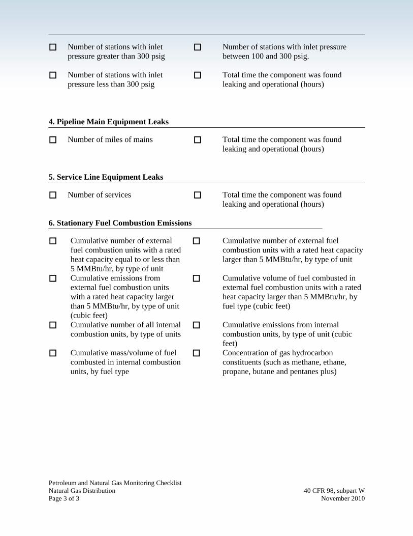
Petroleum and Natural Gas Monitoring Checklist Natural Gas Distribution 40 CFR 98, subpart W Page 3 of 3 November 2010
Number of stations with inlet
pressure greater than 300 psig
Number of stations with inlet pressure between 100 and 300 psig.
Number of stations with inlet pressure less than 300 psig
Total time the component was found leaking and operational (hours)
4. Pipeline Main Equipment Leaks Number of miles of mains Total time the component was found
leaking and operational (hours) 5. Service Line Equipment Leaks Number of services Total time the component was found
leaking and operational (hours) 6. Stationary Fuel Combustion Emissions Cumulative number of external
fuel combustion units with a rated heat capacity equal to or less than 5 MMBtu/hr, by type of unit
Cumulative number of external fuel combustion units with a rated heat capacity larger than 5 MMBtu/hr, by type of unit
Cumulative emissions from external fuel combustion units with a rated heat capacity larger than 5 MMBtu/hr, by type of unit (cubic feet)
Cumulative volume of fuel combusted in external fuel combustion units with a rated heat capacity larger than 5 MMBtu/hr, by fuel type (cubic feet)
Cumulative number of all internal combustion units, by type of units
Cumulative emissions from internal combustion units, by type of unit (cubic feet)
Cumulative mass/volume of fuel combusted in internal combustion units, by fuel type
Concentration of gas hydrocarbon constituents (such as methane, ethane, propane, butane and pentanes plus)

Petroleum and Natural Gas Monitoring Checklist LNG Storage 40 CFR 98, subpart W Page 1 of 5 November 2010
Note: This monitoring checklist does not include changes from the 12/23/11 final rule 76 FR 80554 (Technical Revisions and Clarifications to subpart A and subpart W), or corrections from the pending proposed rule, “2012 Technical Corrections, Clarifying and Other Amendments to the Greenhouse Gas Reporting Rule, and Proposed Confidentiality Determinations for Certain Data Elements of the Fluorinated Gas Source Category." EPA is working to update these checklists. Additional information on the subpart W rules can be found at http://www.epa.gov/climatechange/emissions/subpart/w.html. Reporters should refer to the e-CFR for the final rule (http://ecfr.gpoaccess.gov/cgi/t/text/text-idx?c=ecfr&sid=9415fad5f1c7ea4d940d308e1ea74e11&tpl=/ecfrbrowse/Title40/40cfr98_main_02.tpl). Petroleum and Natural Gas Systems Monitoring Checklist for LNG Storage Final Rule: Mandatory Reporting of Greenhouse Gases (40 CFR Part 98) What must be monitored? If emissions are going to flares, need data elements under the source flare stacks (see Monitoring Checklist for Onshore Petroleum and Natural Gas Production).
Record these parameters on an annual basis, unless specified otherwise. 1. Reciprocating Compressor Rod Packing Venting
Record emissions at each reciprocating compressor in as-found mode. Each mode must be monitored at least once in any three consecutive calendar years. Reciprocating Compressor Emissions in Operating Mode: Rod packing venting from
reciprocating compressor in operational mode (standard cubic feet per hour)
Blowdown vent emissions from reciprocating compressor in operational mode (standard cubic feet per hour)
Total time the compressor is in operating mode (hours)
Annual throughput (million standard cubic feet per day)
Mole fraction of GHG in the vent gas
Reciprocating Compressors Emissions in Standby Pressurized Mode: Blowdown vent emissions from
reciprocating compressor in standby pressurized mode (standard cubic feet)
Total time the reciprocating compressor is in standby, pressurized mode (hours)

Petroleum and Natural Gas Monitoring Checklist LNG Storage 40 CFR 98, subpart W Page 2 of 5 November 2010
Mole fraction of GHG in the vent
gas
Reciprocating Compressors in Shutdown, Depressurized Mode: Unit isolation valve emissions from
reciprocating compressor in shutdown depressurized mode (standard cubic feet)
Total time the reciprocating compressor is in shutdown, depressurized mode (hours)
Mole fraction of GHG in the vent gas
Record emission factors for reciprocating compressors in each mode.
Total annual reciprocating
compressor emissions in operating mode (cubic feet)
Total annual reciprocating compressor emissions in standby, pressurized mode (cubic feet)
Total annual reciprocating compressor emissions in shut down, depressurized mode (cubic feet)
Total number of compressors measured in operating mode
Total number of compressors measured in standby, pressurized mode
Total number of compressors measured in shutdown, depressurized mode
Emission factor for rod packing vent emission in operating mode (cubic feet per hour)
Emission factor for blowdown vent emissions in operating mode (cubic feet per hour)
Emission factor for blowdown vent emissions in standby pressurized mode (cubic feet per hour)
Emission factor for isolation valve in shutdown, depressurized mode (cubic feet per hour)
Record emissions from each reciprocating compressor in all modes and total
annual emissions. Total annual compressor emission
from all modes of operation Total time the compressor is in operating
mode in reporting year (hours)

Petroleum and Natural Gas Monitoring Checklist LNG Storage 40 CFR 98, subpart W Page 3 of 5 November 2010
(standard cubic feet) Total time the reciprocating
compressor is in standby, pressurized mode in reporting year (hours)
Total time the reciprocating compressor is in shutdown, depressurized mode in reporting year (hours)
2. Centrifugal Compressor Wet Seal Degassing Venting
Record emissions at each centrifugal compressor in as-found mode. Each
mode must be monitored at least once in any three consecutive calendar years. Centrifugal Compressor Emissions in Operating Mode: Wet seal oil degassing vents
emissions from centrifugal compressor in operational mode (standard cubic feet per hour)
Blowdown vent emissions centrifugal compressor in operational mode (standard cubic feet per hour)
Total time the centrifugal compressor is in operating mode (hours)
Number of wet seals connected to the degassing vent
Type of meters used for making measurements
Fraction of operating time wet seal degassing vent gas is sent to vapor recovery or fuel gas
Mole fraction of GHG in the vent gas
Annual throughput (million standard cubic feet per day)
Centrifugal Compressors in Not-operating, Depressurized Mode: Unit isolation valve emissions from
centrifugal compressor in shutdown depressurized mode (standard cubic feet)
Total time the centrifugal compressor is in shutdown, depressurized mode (hours)
Mole fraction of GHG in the vent gas
Record emission factors for centrifugal compressors in each mode.
Total annual emissions from all Total annual emissions from all

Petroleum and Natural Gas Monitoring Checklist LNG Storage 40 CFR 98, subpart W Page 4 of 5 November 2010
centrifugal compressor in operating mode (cubic feet)
centrifugal compressor in shut down, depressurized mode (cubic feet)
Total number of centrifugal compressors measured in operating mode
Total number of centrifugal compressors measured in shutdown, depressurized mode
Emission factor for wet seal degassing vent in operating mode (cubic feet per hour)
Emission factor for blowdown vent emissions in operating mode (cubic feet per hour)
Emission factor for isolation valve in shutdown, depressurized mode (cubic feet per hour)
Record e emissions from each centrifugal compressor in all modes and total
annual emissions. Total annual centrifugal compressor
emission from all modes of operation (standard cubic feet)
Total time the centrifugal compressor is in operating mode in reporting year (hours)
Total time the centrifugal compressor is in shutdown, depressurized mode in reporting year (hours)
3. Valves Report CO2 emissions from all
valves (standard cubic feet) Report CH4 emissions from all valves
(standard cubic feet) Operating time of leaking
component (hours) Total number of components found leaking
4. Pump Seals Report CO2 emissions from all
pump seals (standard cubic feet) Report CH4 emissions from all pump seals
(standard cubic feet) Operating time of leaking
component (hours) Total number of components found leaking
5. Connectors Report CO2 emissions from all
connectors (standard cubic feet) Report CH4 emissions from all connectors
(standard cubic feet) Operating time of leaking Total number of components found leaking

Petroleum and Natural Gas Monitoring Checklist LNG Storage 40 CFR 98, subpart W Page 5 of 5 November 2010
component (hours) 6. Vapor Recovery Compressors Report CO2 emissions from all
vapor recovery compressors (standard cubic feet)
Report CH4 emissions from all vapor recovery compressors (standard cubic feet)
Operating time of leaking component (hours)
Total number of components found leaking
7. Other Equipment Report CO2 emissions from all
other equipment (standard cubic feet)
Report CH4 emissions from all other equipment (standard cubic feet)
Operating time of leaking component (hours)
Total number of components found leaking

Petroleum and Natural Gas Monitoring Checklist LNG Import and Export 40 CFR 98, subpart W Page 1 of 5 November 2010
Note: This monitoring checklist does not include changes from the 12/23/11 final rule 76 FR 80554 (Technical Revisions and Clarifications to subpart A and subpart W), or corrections from the pending proposed rule, “2012 Technical Corrections, Clarifying and Other Amendments to the Greenhouse Gas Reporting Rule, and Proposed Confidentiality Determinations for Certain Data Elements of the Fluorinated Gas Source Category." EPA is working to update these checklists. Additional information on the subpart W rules can be found at http://www.epa.gov/climatechange/emissions/subpart/w.html. Reporters should refer to the e-CFR for the final rule (http://ecfr.gpoaccess.gov/cgi/t/text/text-idx?c=ecfr&sid=9415fad5f1c7ea4d940d308e1ea74e11&tpl=/ecfrbrowse/Title40/40cfr98_main_02.tpl). Petroleum and Natural Gas Systems Monitoring Checklist for LNG Import and Export Final Rule: Mandatory Reporting of Greenhouse Gases (40 CFR Part 98) What must be monitored? If emissions are going to flares, need data elements under the source flare stacks (see Monitoring Checklist for Onshore Petroleum and Natural Gas Production).
Record these parameters on an annual basis, unless specified otherwise. 1. Reciprocating Compressor Rod Packing Venting
Record emissions at each reciprocating compressor in as-found mode. Each mode must be monitored at least once in any three consecutive calendar years. Reciprocating Compressor Emissions in Operating Mode: Rod packing venting from
reciprocating compressor in operational mode (standard cubic feet per hour)
Blowdown vent emissions from reciprocating compressor in operational mode (standard cubic feet per hour)
Total time the compressor is in operating mode (hours)
Annual throughput (million standard cubic feet per day)
Mole fraction of GHG in the vent gas
Reciprocating Compressors Emissions in Standby Pressurized Mode: Blowdown vent emissions from
reciprocating compressor in standby pressurized mode (standard cubic
Total time the reciprocating compressor is in standby, pressurized mode (hours)

Petroleum and Natural Gas Monitoring Checklist LNG Import and Export 40 CFR 98, subpart W Page 2 of 5 November 2010
feet)
Mole fraction of GHG in the vent gas
Reciprocating Compressors in Shutdown, Depressurized Mode: Unit isolation valve emissions from
reciprocating compressor in shutdown depressurized mode (standard cubic feet)
Total time the reciprocating compressor is in shutdown, depressurized mode (hours)
Mole fraction of GHG in the vent gas
Record emission factors for reciprocating compressors in each mode.
Total annual reciprocating
compressor emissions in operating mode (cubic feet)
Total annual reciprocating compressor emissions in standby, pressurized mode (cubic feet)
Total annual reciprocating compressor emissions in shut down, depressurized mode (cubic feet)
Total number of compressors measured in operating mode
Total number of compressors measured in standby, pressurized mode
Total number of compressors measured in shutdown, depressurized mode
Emission factor for rod packing vent emission in operating mode (cubic feet per hour)
Emission factor for blowdown vent emissions in operating mode (cubic feet per hour)
Emission factor for blowdown vent emissions in standby pressurized mode (cubic feet per hour)
Emission factor for isolation valve in shutdown, depressurized mode (cubic feet per hour)
Record emissions from each reciprocating compressor in all modes and total
annual emissions. Total annual compressor emission
from all modes of operation (standard cubic feet)
Total time the compressor is in operating mode in reporting year (hours)

Petroleum and Natural Gas Monitoring Checklist LNG Import and Export 40 CFR 98, subpart W Page 3 of 5 November 2010
Total time the reciprocating compressor is in standby, pressurized mode in reporting year (hours)
Total time the reciprocating compressor is in shutdown, depressurized mode in reporting year (hours)
2. Centrifugal Compressor Wet Seal Degassing Venting
Record emissions at each centrifugal compressor in as-found mode. Each
mode must be monitored at least once in any three consecutive calendar years. Centrifugal Compressor Emissions in Operating Mode: Wet seal oil degassing vents
emissions from centrifugal compressor in operational mode (standard cubic feet per hour)
Blowdown vent emissions centrifugal compressor in operational mode (standard cubic feet per hour)
Total time the centrifugal compressor is in operating mode (hours)
Number of wet seals connected to the degassing vent
Type of meters used for making measurements
Fraction of operating time wet seal degassing vent gas is sent to vapor recovery or fuel gas
Mole fraction of GHG in the vent gas
Annual throughput (million standard cubic feet per day)
Centrifugal Compressors in Not-operating, Depressurized Mode: Unit isolation valve emissions from
centrifugal compressor in shutdown depressurized mode (standard cubic feet)
Total time the centrifugal compressor is in shutdown, depressurized mode (hours)
Mole fraction of GHG in the vent gas
Record emission factors for centrifugal compressors in each mode.
Total annual emissions from all Total annual emissions from all

Petroleum and Natural Gas Monitoring Checklist LNG Import and Export 40 CFR 98, subpart W Page 4 of 5 November 2010
centrifugal compressor in operating mode (cubic feet)
centrifugal compressor in shut down, depressurized mode (cubic feet)
Total number of centrifugal compressors measured in operating mode
Total number of centrifugal compressors measured in shutdown, depressurized mode
Emission factor for wet seal degassing vent in operating mode (cubic feet per hour)
Emission factor for blowdown vent emissions in operating mode (cubic feet per hour)
Emission factor for isolation valve in shutdown, depressurized mode (cubic feet per hour)
Record emissions from each centrifugal compressor in all modes and total
annual emissions. Total annual centrifugal compressor
emission from all modes of operation (standard cubic feet)
Total time the centrifugal compressor is in operating mode in reporting year (hours)
Total time the centrifugal compressor is in shutdown, depressurized mode in reporting year (hours)
3. Blowdown Vents Number of repetitive blowdowns
for each equipment type of a unique volume
Total volume of blowdown equipment chambers (including pipelines, compressors and vessels) between isolation valves (cubic feet)
Actual temperature in the blowdown equipment chamber (°F)
Actual pressure in the blowdown equipment chamber (psia)
Emissions per equipment type (cubic feet)
4. Valves Report CO2 emissions from all
valves (standard cubic feet) Report CH4 emissions from all other valves
(standard cubic feet) Operating time of leaking Total number of components found leaking

Petroleum and Natural Gas Monitoring Checklist LNG Import and Export 40 CFR 98, subpart W Page 5 of 5 November 2010
component (hours) 5. Pump Seals Report CO2 emissions from all
pump seals (standard cubic feet) Report CH4 emissions from all pump seals
(standard cubic feet) Operating time of leaking
component (hours) Total number of components found leaking
6. Connectors Report CO2 emissions from all
connectors (standard cubic feet) Report CH4 emissions from all other
connectors (standard cubic feet) Operating time of leaking
component (hours) Total number of components found leaking
7. Vapor Recovery Compressors Report CO2 emissions from all
vapor recovery compressors (standard cubic feet)
Report CH4 emissions from all vapor recovery compressors (standard cubic feet)
Operating time of leaking component (hours)
Total number of components found leaking
8. Other Equipment Report CO2 emissions from all
other equipment (standard cubic feet)
Report CH4 emissions from all other equipment (standard cubic feet)
Operating time of leaking component (hours)
Total number of components found leaking