notice changes introduced as a result of publishing ...eprints.qut.edu.au/58409/2/58409.pdfwhich...
TRANSCRIPT
This is the author’s version of a work that was submitted/accepted for pub-lication in the following source:
Abeysinghe, Chanaka M., Thambiratnam, David P., & Perera, Nimal J.(2013)Dynamic performance characteristics of an innovative Hybrid CompositeFloor Plate System under human-induced loads.Composite Structures, 96, pp. 590-600.
This file was downloaded from: https://eprints.qut.edu.au/58409/
c© Copyright 2013 Elsevier
This is the author’s version of a work that was accepted for publication in Composite Struc-tures. Changes resulting from the publishing process, such as peer review, editing, correc-tions, structural formatting, and other quality control mechanisms may not be reflected inthis document. Changes may have been made to this work since it was submitted for pub-lication. A definitive version was subsequently published in Composite Structures, [VOL96, ISSUE-, (2013)] DOI: 10.1016/j.compstruct.2012.09.015
Notice: Changes introduced as a result of publishing processes such ascopy-editing and formatting may not be reflected in this document. For adefinitive version of this work, please refer to the published source:
https://doi.org/10.1016/j.compstruct.2012.09.015

1
Dynamic performance characteristics of an innovative Hybrid Composite Floor Plate System under human-induced loads
Chanaka M. Abeysinghe 1, David P. Thambiratnam2*, Nimal J. Perera 3
1 PhD student, School of Civil Engineering & Built Environment, Queensland University of
Technology, Brisbane, Australia
([email protected]) 2 Professor, School of Civil Engineering & Built Environment, Queensland University of Technology,
Brisbane, Australia
([email protected]) 3 Adj. Professor, School of Civil Engineering & Built Environment, Queensland University of
Technology, Brisbane, Australia
*Corresponding Author
Abstract
This study explored the dynamic performance of an innovative Hybrid Composite Floor Plate
System (HCFPS), composed of Polyurethane (PU) core, outer layers of Glass-fibre
Reinforced Cement (GRC) and steel laminates at tensile regions, using experimental testing
and Finite Element (FE) modelling. Experimental testing included heel impact and walking
tests for 3200 mm span HCFPS panels. FE models of the HCFPS were developed using the
FE program ABAQUS and validated with experimental results. HCFPS is a light-weight high
frequency floor system with excellent damping ratio of 5% (bare floor) due to the central PU
core. Parametric studies were conducted using the validated FE models to investigate the
dynamic response of the HCFPS and to identify characteristics that influence acceleration
response under human induced vibration in service. This vibration performance was
compared with recommended acceptable perceptibility limits. The findings of this study show
that HCFPS can be used in residential and office buildings as a light-weight floor system,
which does not exceed the perceptible thresholds due to human induced vibrations.
Keywords: Hybrid Composite Floor Plate System, Experimental testing, Finite Element modelling,
Human-induced loads, Vibration, Dynamic performance.

2
1. Introduction
Advancements in material technology have provided the potential for the development of an
innovative and novel Hybrid Composite Floor Plate System (HCFPS) with many desirable
properties being light-weight, easy to construct, economical, demountable, recyclable and
reusable. Component materials of HCFPS include a central Polyurethane (PU) core, outer
layers of Glass-fibre Reinforced Cement (GRC) and steel laminates at tensile regions. GRC is
a fiber-reinforced composite material, comprised of alkali-resistant glass fiber, cement and
sand as the major constituents [1, 2]. PU is a common light-weight foam core material, which
has been extensively utilized in sandwich construction [2-5]. The proposed HCFPS is
assembled using component materials as shown in the Fig. 1. The width of the HCFPS is
limited to 2 m to suit prefabrication and transportation requirements but adjacent panels are
connected together using the slab joint shown in Fig. 1. Span of the HCFPS can be varied by
changing the material properties and sectional configuration. A cold-formed thin perforated
steel laminate is placed at the bottom of the beam to improve tensile strength. To enhance the
support bearing capacity of the panel, the PU core is replaced with a GRC fill in the vicinity
of the supports, as shown in Fig. 1. A low mass PU core at the centre results in a light-weight
structure. As a consequence of the proposed configuration, HCFPS is an easy to construct and
economical floor system. Moreover, the light-weight property of this floor plate results in
reduced load on the supporting beams and columns. Thereby, sizes of gravity load bearing
members can be reduced, yielding economical advantages. HCFPS can also be easily
demounted at the cessation of use. Furthermore, reuse or disposal of component materials of
HCFPS is more convenient compared to other conventional structural materials, thereby
lessening environmental impact. Additionally, PU can be successfully recycled into a variety
of forms with more usable formats [6]. The GRC has lower embodied energy and can be
recycled easier than reinforced concrete [7]. Steel laminate of HCFPS can also be reused.
Therefore, HCFPS offers multifunctional structural properties, making it a viable alternative
for conventional floor systems.

3
Fig. 1. Formulation of HCFPS floor panel
2. Aims, scope and significance of the study and its novelty
A comprehensive research program was carried out to develop HCFPS as a lightweight floor
plate system that can be used in residential and office floors. The static performance
characteristics have been reported in another publication [11] in which the authors
demonstrated the feasibility and the method of developing HCFPS by combining the positive
inherent properties of individual component materials to achieve optimum performance [8-
10]. Static performance of HCFPS was investigated using experimental testing and Finite
Element (FE) modelling [11]. Parametric studies were conducted with sectional
configuration, material properties and span lengths (3 to 7.5 m) as the variable parameters
[10]. These studies showed that HCFPS can be used for floor structures in commercial and
residential buildings to meet static performance requirements. Although HCFPS has been
designed to satisfy static performance requirements, dynamic performance under human
induced loads must also be investigated.
Under human induces loads, this floor system can exhibit excessive vibration as a
consequence of being lightweight. This paper will investigate the dynamic performance of
HCFPS under human induced loads and check whether it complies with the established
comfort and serviceability criteria for human perception given in [12-14]. Currently available
methods [13, 15] for evaluating the dynamic performance of floor plates are applicable only
to those using conventional materials such as composite concrete and steel. They cannot be
directly used to evaluate the dynamic performance of the newly developed HCFPS which
consists of non-conventional materials. In this paper, the dynamic performance of HCFPS is

4
therefore evaluated using experimental testing and FE modelling to verify its applicability in
residential and office floors, and hence to develop design guidelines. From the results of the
present study it was evident that (i) HCFPS exhibits a high first mode natural frequency and
hence resonance with human loads will be a rarity, (ii) it has excellent damping properties
and (iii) it does not exceed the perceptible thresholds when subjected to human induced
walking loads.
3. Experimental testing
Heel impact and walking test were conducted on 3200 mm span HCFPS panels. Heel impact
tests have been successfully demonstrated in the literature, to obtain vibration characteristics
of the floor panels [16, 17]. Acceleration response obtained from the heel impact tests were
used to determine the dynamic characteristics of HCFPS test panels. Walking tests were
conducted on the HCFPS test panels to investigate the vibration pattern under human induced
loads.
3.1 Test panel configuration
Three HCFPS test panels were cast and section configuration and span of test panels are
shown in Fig. 2. The PU core was replaced with a 100 mm GRC in the vicinity of the
supports to enhance the support bearing capacity of test panel (refer to Fig. 2). Casting
procedure of the HCFPS test panel is described in [11]. Experimental test results of this
HCFPS test panel with a single beam was used to validate the FE models. The validated FE
model was extended to investigate the overall dynamic behaviour of proposed HCFPS
configuration with two beams (refer to Fig. 1) and building floor plate systems comprising
HCFPS panels.
(a) Section dimensions

5
(b) GRC fill replacing PU core near supports
Fig. 2. 3200 mm span HCFPS test panel configuration [11]
3.2 Test setup and procedure
Test set up and data acquisition system are shown in Fig. 3 and supporting arrangement of the
test panel is shown in Fig. 4. Steel plates, 10 mm thick and 100 mm wide, were placed under
the slab and beam at the supports to distribute the loads uniformly. The steel plates were
supported by solid circular steel bars and adjustable jacks were used to support the steel bars
under the slab, also seen in Fig. 4.
An average person (70 kg) was asked to stand at the mid span of test panel and to raise their
heels approximately 50 mm and produce a sudden heel impact [16]. A 5g accelerometer and
25 mm LVDT were used to acquire acceleration and deflection data at mid span. Data was
acquired for a 3 second period at a rate of 2049 samples per second.
Walking tests were conducted for the all three HCFPS test panels to obtain their acceleration
response at the mid span. An average weight person walked along the test panel at an average
speed. In general, average frequency of walking is 2 Hz, and therefore, average walking
speed is calculated as 1.5 m/s (stride length is 750 mm) [13]. In the present case it took
approximately 2.2 seconds to walk along the 3200 mm span test panel, giving an approximate
walking speed of 1.5 m/s. Acceleration data at the mid span was acquired for a 3 second
period at a rate of 2049 samples per second using a 5g accelerometer.

6
Fig. 3. Dynamic testing set up
Fig. 4. Test panel supporting arrangement
4. 0 Experimental Results
4.1Heel impact test results
A typical acceleration response of the 5 g accelerometer at mid span for HCFPS test panel is
presented in Fig. 5 As acceleration responses were similar for all test panels, only a typical
representative acceleration response is presented. Displacement time histories at the mid span
were also similar for each panel and a typical displacement-time history plot is shown in Fig.
6. Damping coefficient and first mode natural frequency of the test panels were calculated by
using the heel impact test results.

7
Fig. 5. A typical heel impact acceleration response at mid span
Fig. 6. A typical heel impact displacement response at mid span
4.2 Damping of HCFPS test panels
Time-acceleration plot data was used to calculate the damping coefficient (ς), which is “log
decrement damping” as demonstrated by Ellis [18] in Eq. 1. In this context, first four
successive peaks were used to estimate the damping. Murray [19] stated that modal damping
or true damping is one-half to two-thirds of the value of the log decrement damping. Table 1
shows the damping ratios for each panel and average true damping ratio can be taken as 5%
for HCFPS test panels.
n
oe A
A
nlog
2
1
(1)
8
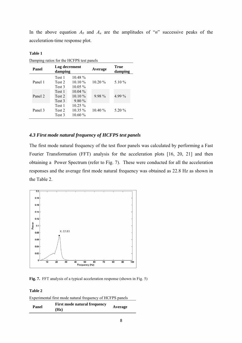
In the above equation A0 and An are the amplitudes of “n” successive peaks of the
acceleration-time response plot.
Table 1
Damping ratios for the HCFPS test panels
4.3 First mode natural frequency of HCFPS test panels
The first mode natural frequency of the test floor panels was calculated by performing a Fast
Fourier Transformation (FFT) analysis for the acceleration plots [16, 20, 21] and then
obtaining a Power Spectrum (refer to Fig. 7). These were conducted for all the acceleration
responses and the average first mode natural frequency was obtained as 22.8 Hz as shown in
the Table 2.
Fig. 7. FFT analysis of a typical acceleration response (shown in Fig. 5)
Table 2
Experimental first mode natural frequency of HCFPS panels
Panel Log decrement damping
Average True damping
Panel 1 Panel 2 Panel 3
Test 1 Test 2 Test 3 Test 1 Test 2 Test 3 Test 1 Test 2 Test 3
10.48 % 10.10 % 10.05 % 10.04 % 10.10 % 9.80 % 10.25 % 10.35 % 10.60 %
10.20 % 9.98 % 10.40 %
5.10 % 4.99 % 5.20 %
Panel First mode natural frequency (Hz)
Average

9
4.4 Walking test results
Acceleration responses obtained from the walking test were similar for all three test panels.
Hence, only a typical representative acceleration response of the 5 g accelerometer at mid
span for HCFPS test panel is presented in Fig. 8.
Fig. 8. Typical acceleration response at the mid span for walking test
5. Implication of test results and discussion
First mode natural frequency of the test panel was estimated as 22.8 Hz, and this can be
verified using an analytical method as follows. The first mode natural frequency of a beam
can be determined by a simplified analytical method (refer to Eq. 2) suggested in [13]. An
equivalent beam section for the HCFPS was determined using the flexural rigidity (EI
=6.76×10^11 Nmm2) of the HCFPS section [11]. HCFPS test panels were weighed and the
average weight was recorded as 202 kg. These parameters were substituted in to Eq. 2 to
obtain the first mode natural frequency as 24.74 Hz. In this equation, EI is flexural rigidity of
the member, m is the effective mass (for a simply supported beam 50% of the total mass) and
L is the span. The analytical first mode natural frequency varies by only 8.5% from the
experimentally obtained value of 22.8 Hz. From Eq. 2, the parameters that influence the first
mode natural frequency of the HCFPS can be identified as the flexural rigidity and the self-
weight. Flexural rigidity of the HCFPS panel is similar to that of conventional floor systems
Panel 1 Panel 2 Panel 3
22.91 22.83 22.66
22.8 Hz

10
[11], but the self-weight of HCFPS panel is lower. The self weight of a 3.2m span, 1m wide
conventional steel-deck composite floor system is 793kg [16, 22] while the self weight of the
same sized HCFPS panel is 202 kg. The first mode natural frequency of HCFPS floors is
therefore higher due to its lighter weight.
31 2 mL
EIf
(2)
Acceleration response of the HCFPS at mid-span obtained from the walking test (refer to Fig.
8), exhibits impulsive behaviour (high frequency floor response) and response decays with
time before the next step. In high frequency floors, the transient response is more significant
than the steady state response. In these floors, resonance will not normally occur due to the
difference between the natural and excitation frequencies, and hence the applied forces
behave like a series of impulses [13].
Damping ratio of the HCFPS was 5% (bare floor), and this value is greater than the damping
values of conventional floor structures, such as concrete and steel-deck composite floor
systems (damping ratio -1.5 to 2 %) [16, 22-24]. This higher damping was achieved due to
the presence of the PU which has better damping characteristics [25]. The HCFPS test panel
exhibited a linear load-deflection response up to 10 mm central deflection during the static
loading test and the serviceability deflection limit of span /360 limit was 8.30 mm [11]. The
peak displacement at the mid span due to the heel impact was 0.9 mm (refer to Fig. 6) thus,
dynamic deflection amplification due to heel impact was small and did not exceed
serviceability deflection limit.
Experimental test results of the HCFPS were used to validate the FE models which were used
to study parametric variations and vibration response under human induced walking loads.
6. FE model development and validation using dynamic test results - now 5?
The commercially available FE program ABAQUS 6.9-1 [26] was used with ABAQUS CAE
as the pre- and post-processor for the FE simulations. The authors have demonstrated in [11]
the excellent validation of the FE model for the load-deflection response under static loading.
In the present study, FE model for the HCFPS test panel is developed to conduct free
vibration analysis and to simulate heel impact and walking tests.

11
6.1 Material properties for dynamic analysis
Dynamic analysis of FE models of the HCFPS was conducted using linear elastic properties
of the component materials. A comprehensive material testing program was conducted and
details are presented in [11]. Material responded within elastic limits for free vibration and
human induced vibration analysis [13] and hence the following properties listed in Table 3
were used in the analysis.
Table 3
Component material properties for the dynamic analysis [11]
Properties PU GRC Steel
Elastic Modulus (Mpa) Poisons ratio (ν) Density (kg/m3)
22.4 0.30 100
5000 0.24 1983
210,000 0.30 7800
6.2 Model description
HCFPS test panel was modelled using ABAQUS, as shown in Fig. 9. 10 mm thick and 100
mm wide steel plates were modelled under the HCFPS panel (refer to Fig. 9a) in order to
simulate the experimental conditions, at the support of HCFPS. Translations in X, Y and Z
directions and rotations in Y and Z directions were restrained at one end whilst translations in
X and Y directions and rotations in Z and Y directions were restrained at the other end (refer
to Fig. 9) in order to simulate the restraint from the steel bars (used in the tests).
(a) Support
(b) Mesh
12
Fig. 9. FE model for HCFPS test panel
C3D8R eight node liner brick elements were used in the FE model for all parts along with
reduced integration and hourglass control [27]. Convergence study was conducted to select
the optimum mesh size for the FE model. Maximum element size according to that study was
25 mm, and FE mesh is shown in Fig. 9b.
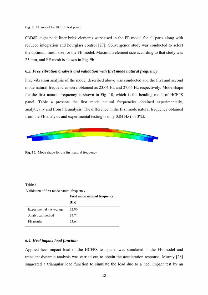
6.3. Free vibration analysis and validation with first mode natural frequency
Free vibration analysis of the model described above was conducted and the first and second
mode natural frequencies were obtained as 23.64 Hz and 27.66 Hz respectively. Mode shape
for the first natural frequency is shown in Fig. 10, which is the bending mode of HCFPS
panel. Table 4 presents the first mode natural frequencies obtained experimentally,
analytically and from FE analysis. The difference in the first mode natural frequency obtained
from the FE analysis and experimental testing is only 0.84 Hz ( or 3%).
Fig. 10. Mode shape for the first natural frequency
Table 4
Validation of first mode natural frequency
First mode natural frequency
(Hz)
Experimental - Avegrage
Analytical method
FE results
22.80
24.74
23.64
6.4. Heel impact load function
Applied heel impact load of the HCFPS test panel was simulated in the FE model and
transient dynamic analysis was carried out to obtain the acceleration response. Murray [28]
suggested a triangular load function to simulate the load due to a heel impact test by an

13
average weight person. Load function is a 2670 N initial load that linearly decreases to zero
over a period of 0.05 seconds, which represents an impulse of 67 Ns [28]. This method was
used successfully to validate a FE model for the acceleration response of a heel drop test
performed on a post-tensioned concrete slab [17]. The suggested load function was applied to
the FE model of HCFPS test specimen as shown in Fig. 11 and represents a typical heel
impact test of the panel. The corresponding acceleration response of the HCFPS is shown in
Fig. 5.
Fig. 11. Heel impact load function
6.5. Application of damping to FE models
The true damping ratio (ζ) obtained experimentally as 5% is used in the FE model for the
transient dynamic analysis. Clough et al. [29] defined the damping in transient dynamic
analysis problems using an explicit damping matrix, by incorporating the damping ratio.
Damping matrix is assumed to be a combination of mass proportional damping (α) and the
stiffness proportional damping (β), known as Reyleigh proportional damping method [29].
This method has been previously used [16] to incorporate damping in floor models. It can be
assumed that the variation of damping ratios for first two natural frequencies is negligible and
(ζ1= ζ2= ζ) [16, 29]. Hence, α and β can be calculated using Eqn. 3 [16, 29] by substituting ζ
and first two natural frequencies f1=23.64 Hz and f2=27.66 Hz as 1.245 and 0.002
respectively.
1
2 21
21
ff
ff
(3)
0
500
1000
1500
2000
2500
3000
0 0.5 1 1.5 2 2.5 3
Fo
rce
(N)
Time (Seconds)

14
6.6. Dynamic analysis validation with acceleration response
Heel impact load function described above was applied with Raleigh damping to obtain
acceleration response of the FE model. "Modal Dynamic" analysis procedure available in
ABAQUS [26] was used to conduct linear transient modal dynamic analysis. Acceleration
obtained from the FE analysis was compared with experimental response as shown in Fig. 12.
This demonstrates excellent validation, as peak acceleration values and durations of the
response decay obtained from the FE analysis agree well with those from the experiments.
(a) FE acceleration time history
(b) Heel impact acceleration time history

15
Fig. 12. Computed and measured acceleration responses
6.7. Walking response of HCFPS test panel
Walking of a person along the HCFPS test panel was simulated using FE techniques. Pan et
al. [30] suggested a method to model a single person’s walking steps by using point loads.
Distance between successive strides was calculated using the pacing frequency. Hence,
footfall interval is 0.5 s for a pacing frequency of 2 Hz and thus gives a stride length of 750
mm [31, 32]. Average point load applied on a floor due to a single step at an average walking
speed (2 Hz) is 616 N [31, 32]. This load model was applied to the FE model of HCFPS
with damping data as described in section 4.5. By conducting transient dynamic analysis,
acceleration response was obtained as shown in Fig. 13. It is evident that the acceleration
response obtained from FE analysis is similar to the experimental walking response shown in
Fig. 8.
Fig.13. Computed acceleration responses at mid span for single person walking
The FE models validated in this study will be used to carry out further parametric studies on
the dynamic response characteristics of the HCFPS panels.
7. Parametric studies of HCFPS panels
Previous studies [10, 11] demonstrated that HCFPS panels can be used in floor construction
to satisfy the static performance requirements, such as deflection limits and shear and flexural
strength capacities. The present parametric studies using experimentally validated FE models.
will compare the dynamic performance of HCFPS under human induced loads for vibration

16
performance with acceptable perceptibility limits [12-14] in commercial and residential
buildings
7.1. Structural configuration
Sectional configuration, material properties and span lengths (3 to 7.5 m) used in previous
studies, satisfied static performance requirements [10, 11]. Dead and imposed loads for the
design complied with AS 1170 [33] for commercial and residential floors. Flexural stress and
shear stress at the ultimate loading were within the individual capacities of materials [10, 11].
Based on the outcome of the static performance study [10] rectangular beam sections have
been selected for detailed analysis. Three section configurations (A, B and C type sections)
for the representative spans were selected to investigate the dynamic performance. Spans and
section configuration parameters are shown in Fig. 14 and Table 5. Material properties that
were determined to suit the static performance requirements for these sections are listed in
Table 6.
Fig. 14. Sectional configuration parameters
Table 5
Spans and section dimensions
Section Type Span (m)
a (mm)
d (mm)
h (mm)
A B C
3.0 5.0 7.5
100 150 200
60 80 80
200 350 450
Table 6
Material properties
Properties PU GRC Steel
17
Density (kg/m3) E (Mpa) Poisons ratio
100 22.4 0.3
1900 10,000 0.24
7800 210,000
0.3
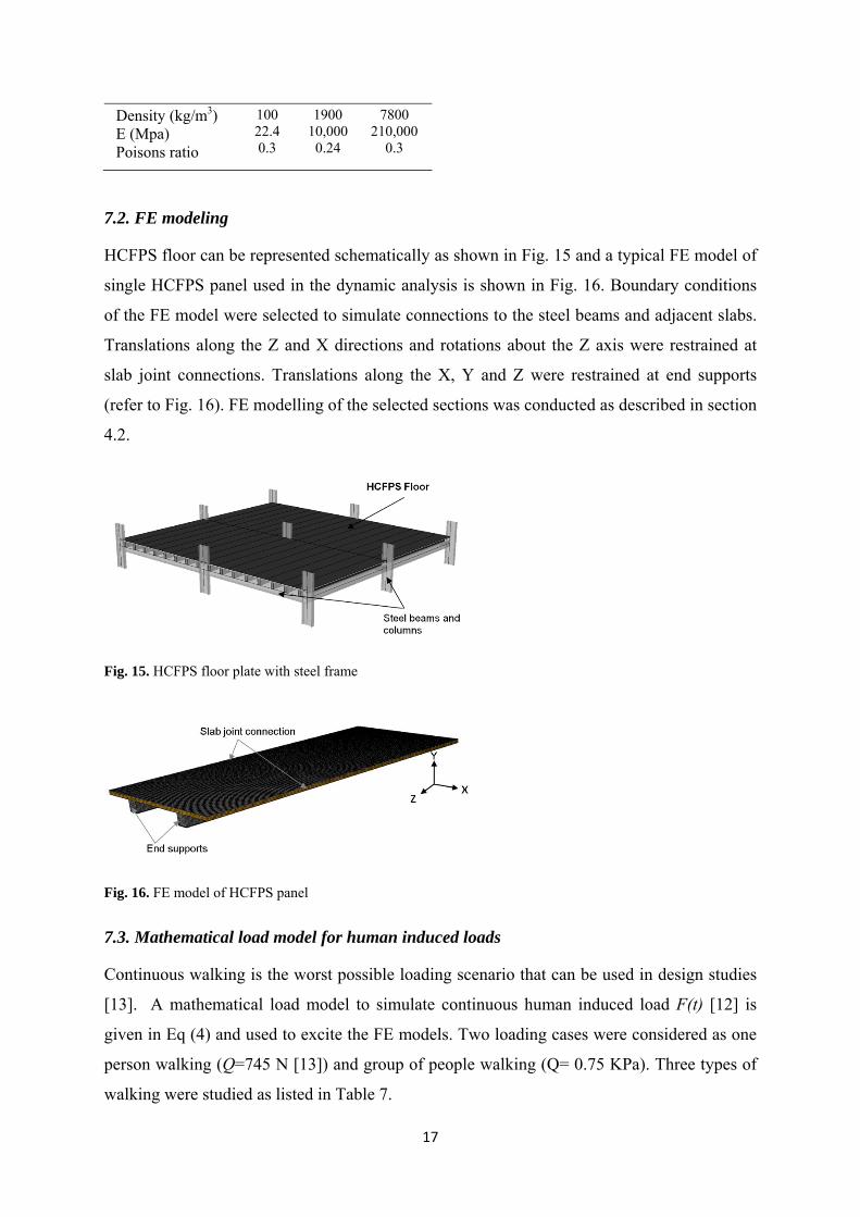
7.2. FE modeling
HCFPS floor can be represented schematically as shown in Fig. 15 and a typical FE model of
single HCFPS panel used in the dynamic analysis is shown in Fig. 16. Boundary conditions
of the FE model were selected to simulate connections to the steel beams and adjacent slabs.
Translations along the Z and X directions and rotations about the Z axis were restrained at
slab joint connections. Translations along the X, Y and Z were restrained at end supports
(refer to Fig. 16). FE modelling of the selected sections was conducted as described in section
4.2.
Fig. 15. HCFPS floor plate with steel frame
Fig. 16. FE model of HCFPS panel
7.3. Mathematical load model for human induced loads
Continuous walking is the worst possible loading scenario that can be used in design studies
[13]. A mathematical load model to simulate continuous human induced load F(t) [12] is
given in Eq (4) and used to excite the FE models. Two loading cases were considered as one
person walking (Q=745 N [13]) and group of people walking (Q= 0.75 KPa). Three types of
walking were studied as listed in Table 7.

18
kn npn tnfQtF 1 )2sin(1)( (4)
In the above Eq., F(t) is the dynamic force, Q is the static weight of the participating person,
n is the Fourier coefficient corresponding to nth harmonic, fp is the pacing frequency, t is the
time and n is the phase angle of the nth harmonic, n is the integer designating harmonic of
the fundamental and k is the number of harmonics that characterise the forcing function in
the frequency range of interest. Phase shift of 900 for each harmonics was used [12]. The
numerical values of the first four Fourier coefficients used to model the human walking load
are listed in Table 7.
Table 7
Parameters for the load model[12]
Mode of
walking fp (Hz)
Numerical coefficient for 1st four harmonics
1 2 3 4
Slow Walk
Normal Walk
Fast Walk
1.7
2.0
2.4
0.26
0.37
0.52
0.1
0.1
0.1
0.06
0.06
0.06
0.06
0.06
0.06
7.4. Mass of the HCFPS
The dynamic performance of office and residential floors should be investigated using a floor
mass that represents actual service loads [13]. The floor mass should be equivalent to the
summation of self-weight of floor plate and super imposed dead loads due to finishes, ceiling,
services and partitions. 10% of the nominal imposed loads (1.5 kPa for residential and 3.0
kPa for office floors) can also be added as permanent loads [13]. Super imposed dead loads,
which gives a total of 1.0 kPa are summarised in Table 8 [33]. This value could be increased
up to 2.0 kPa in residential buildings due to higher density of partition walls and heavier floor
finishes. In the present study, a uniform super imposed dead load of 1.0 kPa was used in the
dynamic analysis of HCFPS floors.
Table 8
Super imposed permanent dead loads for a office floor

19
Type of loading Load, kPa
Floor finishes acoucstic insulation + cladding Suspended ceiling Suspended services Light weight partition, furniture and equipments Fire protection
0.25
0.10 0.15 0.35
0.15
7.5. Damping
Damping ratio of concrete and steel-deck composite bare floor systems are in the range of 1.5
to 2 % [16, 22-24]. Damping ratio of conventional floors with finishes and partitions is in the
range of 4.5% - 6% [19, 34]. There is approximately 2 to 4% increase in damping ratio due
to the finishes and partition in floor structures. True damping level of 5% has been evaluated
from experimental testing of HCFPS test panel. Vibration responses of HCFPS floors were
comparatively studied using 3% and 5% damping ratios in the parametric studies. Damping
was incorporated into the FF models as explained in section 4.5.
7.6. Material properties
Optimum material properties of GRC and steel were determined for the A, B and C type
sections to achieve acceptable stiffness, flexural and shear capacities in static performance
investigation [10, 11]. Properties of GRC and steel were not changed for the present
parametric study and were the same as those obtained for the static performance requirements
(Table 6). Properties of PU in have negligible effect on the structural capacity of HCFPS
section [10, 11]. Elastic modulus of PU changes with density [35] and properties of PU as
listed in Table 9 are well established and used in construction applications [3, 36, 37].
Table 9
Properties of PU
Properties PU
Density (kg/m3) E (Mpa) Poisons ratio
100 22.4 0.3
200 76.1 0.3
300 151.6
0.3
7.7. FE analysis
Parameters as described above were varied in the FE model of A, B and C type HCFPS
sections. Free vibration analysis was conducted to obtain the modal frequencies. Transient

20
dynamic analysis was performed using continuous walking loads to obtain the acceleration
response.
7.8. Results from parametric study and discussion
A, B and C types HCFPS floors can be categorised as high frequency floors as all panels
exhibited high first mode natural frequency (f1). Change in PU properties affected marginally
on f1 and average values were estimated at 40 Hz, 28 Hz and 17 Hz for A, B and C type
sections respectively. Acceleration responses due to a single person walking and due to a
dynamic distributed load, which represents a group of people, were observed to be similar.
This kind of behaviour is supported by published findings from previous studies [38].
Walking path was changed to different positions on the slab, but there was no significant
change in the acceleration response. For all walking positions, the highest acceleration
response was observed at the mid span of HCFPS section, and this was used for subsequent
vibration assessments.
Response of a floor structure is evaluated in terms peak acceleration and Root-Mean Square
(RMS) acceleration (arms). Peak acceleration is the highest value of acceleration resulting
from an excitation but it does not provide a measure of the duration of the response. In
contrast, RMS acceleration is an average measurement of the acceleration time-history, as
shown in the Eq. (5). Smith et al. [13] stated that sharp peaks of acceleration are less
significant with lower (arms). T is the period under consideration in Eq. (5) and (T= 1
second) was used as suggested by Smith et al [13]. This covers at least one complete cycle of
acceleration due to walking activities with an average frequency of 2 Hz (T= 0.5s) [13].
Acceleration response was obtained from the FE analysis and arms was calculated using Eq.
(5). All three HCFPS panels were high frequency floors and thus arms acceleration must be
frequency weighted using a factor of 8/f1 for such floors to obtain the frequency weighted
RMS acceleration (aw,rms) according to [12, 13]. Variation of aw,rms values of A, B and C
sections with change in parameters are shown in Fig. 17, 18, 19.
T
rms dttaT
a0
2)(1
(5)

21
Fig. 17. RMS acceleration for section type A, and 3 m span
Fig. 18. RMS acceleration for section type B, and 5 m span
0
0.01
0.02
0.03
0.04
0.05
0.06
0.07
1.7 1.7 2 2 2.4 2.4
a w
,rm
s (m
s-2 )
fp (Hz)
300
200
100
5% 3% 5% 3% 5% 3% ζ
fp = Forcing frequency , ζ - Damping ratio
PU Density kg/m3
0
0.01
0.02
0.03
0.04
0.05
0.06
0.07
0.08
0.09
1.7 1.7 2 2 2.4 2.4
a w,r
ms
(ms-
2 )
fp (Hz)
300
200
100
5% 3% 5% 3% 5% 3% ζ
fp = Forcing frequency , ζ - Damping ratio
PU Density kg/m3

22
Fig. 19. RMS acceleration for section type C, and 7.5 m span
aw,rms values vary in a similar pattern with change in forcing frequency, damping ratio and
PU density for A, B and C HCFPS sections according to Fig. 17, 18, 19. The lowest aw,rms
can be seen for slower walking and the highest aw,rms is seen for fast walking. aw,rms changed
marginally due to the increase in properties of PU core. aw,rms and it decreased by
approximately 50 % when the damping ratio changed from 3 % to 5%.
RMS acceleration values were estimated using the continuous loading model described in
section 5.3. For assessing the effect of vibration, a cumulative measure of the vibration
response for intermittent activities is more reliable and needs to be used for determining
perceptible levels. ISO 10137 [12] and BS 6472 [14] provide perceptive tolerance levels for
the intermittent vibrations using the Vibration Dose Value (VDV ) which can be calculated
using Eq. 6, in which aw is the frequency weighted acceleration and T is the total duration of
the vibration [14].
41
04)( T
w dttaVDV (6)
Ellis [39] suggested an alternate procedure, as given in Eq. 7 to calculate VDV values of a
walking activity by using the aw,rms in the design stage of floors and this was used in the
present study. In Eq.7, na is the number of times the activity will take place in the exposure
period and Ta is the duration of an activity (time taken to walk along the floor)
4,68.0 aarmsw TnaVDV (7)
0
0.02
0.04
0.06
0.08
0.1
0.12
1.7 1.7 2 2 2.4 2.4
a w,r
ms
(ms-
2 )
fp (Hz)
300
200
100
5% 3% 5% 3% 5% 3% ζ
fp = Forcing frequency , ζ - Damping ratio
PU Density kg/m3
23
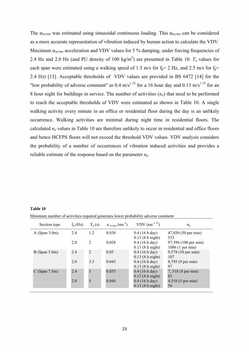
The aw,rms was estimated using sinusoidal continuous loading. This aw,rms can be considered
as a more accurate representation of vibration induced by human action to calculate the VDV.
Maximum aw,rms acceleration and VDV values for 5 % damping, under forcing frequencies of
2.4 Hz and 2.0 Hz (and PU density of 100 kg/m3) are presented in Table 10. Ta values for
each span were estimated using a walking speed of 1.5 m/s for fp= 2 Hz, and 2.5 m/s for fp=
2.4 Hz) [13]. Acceptable thresholds of VDV values are provided in BS 6472 [14] for the
"low probability of adverse comment" as 0.4 m/s1.75 for a 16 hour day and 0.13 m/s1.75 for an
8 hour night for buildings in service. The number of activities (na) that need to be performed
to reach the acceptable thresholds of VDV were estimated as shown in Table 10. A single
walking activity every minute in an office or residential floor during the day is an unlikely
occurrence. Walking activities are minimal during night time in residential floors. The
calculated na values in Table 10 are therefore unlikely to occur in residential and office floors
and hence HCFPS floors will not exceed the threshold VDV values. VDV analysis considers
the probability of a number of occurrences of vibration induced activities and provides a
reliable estimate of the response based on the parameter na.
Table 10
Minimum number of activities required generates lower probability adverse comment
Section type fp (Hz) Ta (s) a w,rms (ms-2) VDV (ms-1.75) na
A (Span 3.0m) B (Span 5.0m) C (Span 7.5m)
2.4 2.0 2.4 2.0 2.4 2.0
1.2 2 2 3.3 3 5
0.038 0.028 0.05 0.045 0.055 0.048
0.4 (16 h day) 0.13 (8 h night) 0.4 (16 h day) 0.13 (8 h night) 0.4 (16 h day) 0.13 (8 h night) 0.4 (16 h day) 0.13 (8 h night) 0.4 (16 h day) 0.13 (8 h night) 0.4 (16 h day) 0.13 (8 h night)
47,850 (50 per min) 533 97,396 (100 per min) 1086 (1 per min) 9,578 (10 per min) 107 8,795 (9 per min) 97 7, 518 (8 per min) 83 4,510 (5 per min) 50

24
8. Conclusions
A comprehensive research project was undertaken to develop an innovative HCFPS
composed of PU, GRC and steel laminate. The work presented in this paper is an integral part
of the comprehensive research program and investigated the dynamic performance
characteristics of the HCFPS using experimental testing and FE modeling. Heel impact tests
and walking tests were carried out using 3200 mm span HCFPS test panels. FE models were
created using ABAQUS and validated against experimental results. Parametric studies were
carried out using the validated FE models. The main findings of this paper are as follows:
The first mode natural frequency of HCFPS floor system is greater than 10 Hz and hence
HCFPS can be categorised as a high frequency floor system. The maximum possible fourth
harmonic of the walking frequency (2.4 Hz) is lower than the first mode natural frequency
[13] and this makes resonant vibration a rarity.
HCFPS is a light-weight high frequency floor system with better than normal vibration
damping characteristics. This light weight floor system will hence provide significant
economic benefits in the design of the supporting system and will have favourable response
under seismic loads.
Its excellent damping ratio of 5% is considered conservative based on experimental tests on
the bare HCFPS test panels. In practical applications, HCFPS floors will have superimposed
dead loads higher than 1.0 kPa and based on existing studies a damping ratio of 5 % is
feasible due to partitions, suspended services and floor finishes. Light-weight HCFPS floor
systems can therefore be effectively designed for use in office and residential buildings to
provide acceptable vibration performance.
Optimum sectional configuration and material properties for static performance requirements
were found to be adequate to provide acceptable vibration performance. Vibration response
of HCFPS under walking activities does not exceed the perceptible threshold of VDV that
was estimated in accordance with BS 6472 [14]. Satisfying this criterion provides further
confirmation that HCFPS can achieve acceptable vibration response under human induced
loads.
Density of PU core can be maintained at 100 kg/m3 for all HCFPS panels with acceptable
vibration performance. PU core is subjected to low stress but provides integrity of the HCFPS

25
section as an infill material for the GRC. Alternative materials, which can maintain overall
integrity of the HCFPS section, can be used instead of PU core, if necessary.
Acceptable performance for lager spans can be achieved by changing component material
properties and section configurations.
Component materials make the HCFPS light-weight, easy to construct, economical,
demountable, recyclable and reusable floor system. Light-weight prefabricated HCFPS
facilitates the transport, handling and erection process. Hence, HCFPS can be used as a viable
alternative for conventional floor systems.
Acknowledgments
Authors are grateful to the Domeshell Technology Pty Ltd. who contributed generously all
the necessary test materials.
References
1. Ferreira, J.G. and F.A. Branco, GRC mechanical properties for structural applications, in Instute Superior Techno. 2004: Portugal. p. 1049-001.
2. Nasir, A.M., D.P. Thambiratnam and C. Button, Performance Characteristics of Compound Curved Sandwich Shell Structures. Journal of the International Association for Shell and Spatial Structures 2012;53(1): 19-30.
3. Braun, D., S.J. Kennedy, D.J.L. Kennedy and D.E. Allen, Sandwich Plate System Risers for Stadia, SSRC 2002 Annual Stability Conference, 2002, Seattle, Washington, USA.
4. Fam, A. and T. Sharaf, Flexural performance of sandwich panels comprising polyurethane core and GFRP skins and ribs of various configurations. Composite Structures 2010;92(12): 2927-2935.
5. Sharaf, T. and A. Fam, Experimental Investigation of Large-Scale Cladding Sandwich Panels under Out-of-Plane Transverse Loading for Building Applications. Journal of Composites for Construction 2011;15(3): 422-430.
6. Zia, K.M., H.N. Bhatti and I.A. Bhatti, Methods for polyurethane and polyurethane composites, recycling and recovery: A review. Reactive & Functional Polymers 2007;67: pp 675-692.
7. GRC In Action. International Glassfibre Reinforced Concrete Association [Internet], 2003. Available from: http://www.bcmgrc.com/general_grcinaction.pdf.
8. Abeysingh, C.M., D.P. Thambiratnam and N.J. Perera, Development of an Innovative Hybrid-Composite Floor System, In Thirteenth International Conference on Civil, Structural and Environmental Engineering Computing, B.H.V. Topping and Y. Tsompanakis, Editors. 2011, Civil-Comp Press, Stirlingshire, Scotland: Chania, Crete, Greece.
9. Abeysingh, C.M., D.P. Thambiratnam and N.J. Perera, Investigation of hybridized polyurethane, glass fibre reinforced cement and steel laminate in structural floor plate systems, In The First International Postgraduate Conference on Engineering, Designing and Developing the Built Environment for Sustainable Wellbeing. 2011, Queensland University of Technology. p. 249-253.
10. Abeysingh, C.M., D.P. Thambiratnam and N.J. Perera, Innovative Hybrid Composite Floor Plate System In AES-ATEMA’2012 Tenth International Conference, Y.M. Haddad, Editor. 2012: McGill University, Montreal, Canada.

26
11. Abeysinghe, C.M., D.P. Thambiratnam and N.J. Perera, Flexural performance of an innovative Hybrid Composite Floor Plate System comprising Glass-fibre Reinforced Cement, Polyurethane and steel laminate. Composite Structures (accepted and will be published in 2012).
12. ISO 10137, Bases for Design of Structures- Serviceability of Buildings Against Vibrations, 2007. International Standardisation Organisation: Geneva Switzerland.
13. Smith, A.L., S.J. Hicks and P.J. Devine, Design of Floors for Vibration: A New Approach.Ascot, Berkshire, UK: The Steel Construction Institute, 2007.
14. BS 6472-1:2008, Guide to evaluation of human exposure to vibration in buildings. Vibration sources other than blasting 2008. British Standards: BSI, UK.
15. Murray, T.M., D.E. Allen and E.E. Ungar, AISC Steel Design Guide Series 11: Floor Vibrations Due to Human ActivityChicago, Illinois: American Institute of Steel Construction, 2003.
16. Sandun De Silva, S., Vibration Characteristics of Steel-Deck Composite Floors under Human Exitation, in School of Urban Development, Faculty of Build Environment and Engineering. 2007, QUT Brisbane.
17. Jetann, C., Development of the Response Coefficient-Root Function Method for the Transient Vibration Serviceability Design of Flat Conctere Floors, in School of Urban Development, Faculty of Build Environment and Engineering. 2010, QUT Brisbane.
18. Ellis, B.R., Dynamic monitoring, in Monitoring and Assessment of Structures. 2001a: New York. p. 8-31.
19. Murray, T.M., Floor Vibrations: Tips for designers of office buildings Structure 2000;26-30. 20. Paskalov, A. and S. Reese, Deterministic and probabilistic floor response spectra. Soil
Dynamics and Earthquake Engineering 2003;23(7): 605-618. 21. Rainer, J.H., Dynamic tests on a steel-joist concrete-slab floor. Canadian Journal of Civil
Engineering 1980;7(2): 213-224. 22. Sandun De Silva, S. and D.P. Thambiratnam, Dynamic characteristics of steel-deck
composite floors under human-induced loads. Computers & Structures 2009;87: 1067-1076. 23. Osborne, K.P. and B.R. Ellis, Vibration design and testing of a long-span lightweight floor.
The Structural Engineer 1990;68(15): 181-186. 24. Wyatt, T.A., Design gude on the vibration of floorAscot, Berkshire, UK: The Steel
Construction Institute UK, 1989. 25. Yoon, K.H., S.T. Yoon and O.O. Park, Damping Properties and Transmission Loss of
Polyurethane. ( I. Effect of Soft and Hard Segment Compositions). Applied polymer science 1999;75: pp 604-611.
26. Abaqus Analysis User's Manual, Version 6.9-1: ABAQUS Inc. 27. Sun, E.Q., Shear locking and hourglassing in msc nastran, abaqus, and ansys. 2006, MSC
Software. 28. Murray, T.M., Design to Prevent Floor Vibrations. AISC Engineering Journal 1975;12(3): 82-
87. 29. Clough, R.W. and J. Penzien, Dynamic of structuresNew York: McGraw-Hill, Inc, 1993. 30. Pan, T., X. You and C. Lim, Evaluation of Floor Vibration in a Biotechnology Laboratory
Caused by Human Walking. Journal of Performance of Constructed Facilities 2008;22(3): 122-130.
31. Živanović, S., A. Pavic and P. Reynolds, Vibration serviceability of footbridges under human-induced excitation: a literature review. Journal of Sound and Vibration 2005;279(1–2): 1-74.
32. Guidelines on the Design for Floor Vibration due to Human Actions Part II: Floor Vibration due to Walking LoadsHong Kong: Structural engineering branch, Architectural services department (ArchSD), 2009.
33. AS/NZS 1170.1, Structural design actions, Part 1: Permanent, imposed and other actions, 2002. Standards Australia: Sydney, NSW, Australia.

27
34. Elnimeiri, M. and H. Iyenga, Composite floor vibrations: predicted and measured in Steel Structures. 1989, American Society of Civil Engineers: San Francisco, CA, USA.
35. Sharma, R.S. and V.P. Raghupathy, Shear Properties of Polyurethane Foams with Different Densities. International Journal of Materials Sciences 2008;3(3): PP 289-297.
36. Sharma, R.S. and V.P. Raghupathy, A Holistic Approach to Static Design of Sandwich Beams with Foam Cores. Journal of Sandwich Structures and Materials 2008;10(5): 429-441.
37. Thirumal, M., D. Khastgir, N.K. Singha, B.S. Manjunath and Y.P. Naik, Effect of Foam Density on the Properties of Water Blown Rigid Polyurethane Foam. Journal of Applied Polymer Science 2008;108: 1810-1817.
38. Ellis, B.R., On the response of long span floors to walking loads generated by individuals and crowds. The Structural Engineer 2000;78: 17-25.
39. Ellis, B.R., Serviceability evaluation of floor vibration induced by walking loads. Structural Engineer 2001;79(21): 30-36.