**notice** - extreme flightextremeflightrc.com/assets/images/manuals/3dh-common_manuals/3dh...we...
TRANSCRIPT
1
**NOTICE** This is only a recommended installation procedure for one type of engine. Different types and brands of engines may require different procedures. This is just a guide to how we install the
Desert Aircraft DA-50 Gasoline Engine with 3D Hobby Shop 50cc Airframe. NOTE: DLE-55 engine installation is nearly identical.
--3D Hobby Shop--
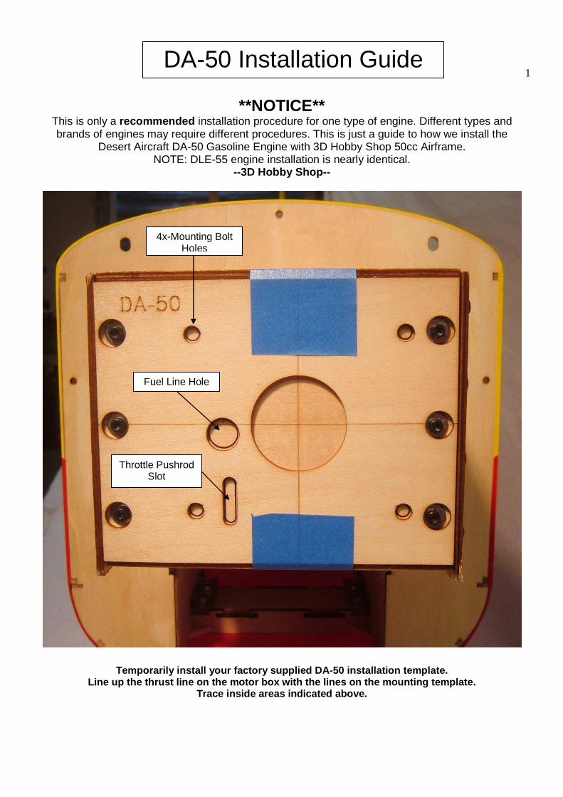
Temporarily install your factory supplied DA-50 ins tallation template. Line up the thrust line on the motor box with the l ines on the mounting template.
Trace inside areas indicated above.
DA-50 Installation Guide
4x-Mounting Bolt Holes
Fuel Line Hole
Throttle Pushrod Slot
2
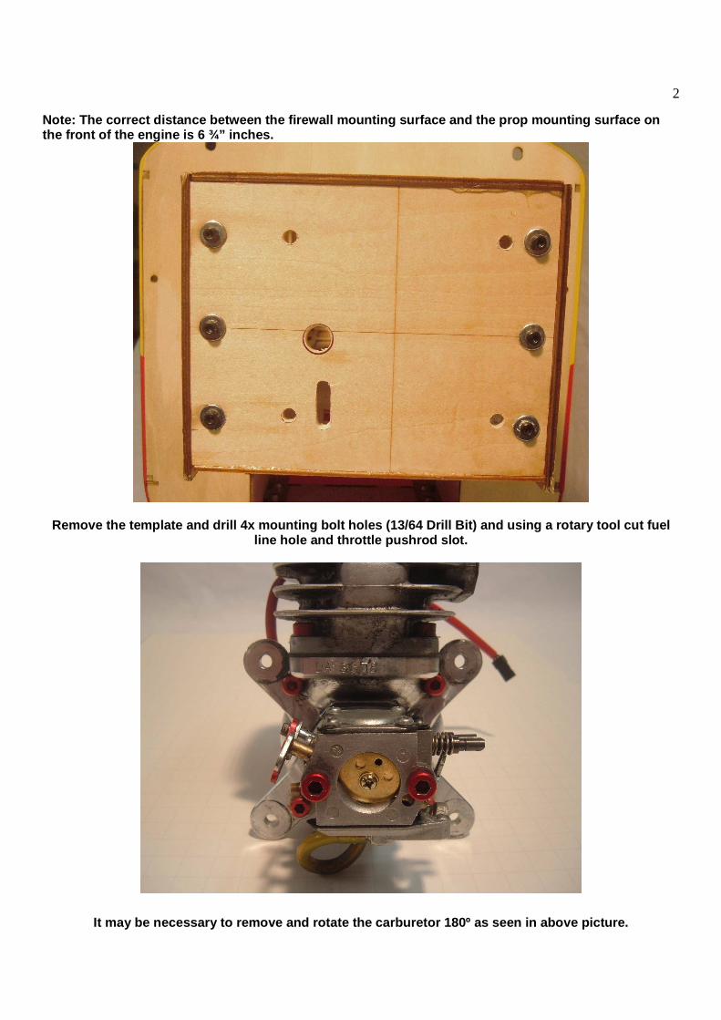
Note: The correct distance between the firewall mou nting surface and the prop mounting surface on the front of the engine is 6 ¾” inches.
Remove the template and drill 4x mounting bolt hole s (13/64 Drill Bit) and using a rotary tool cut fue l line hole and throttle pushrod slot.
It may be necessary to remove and rotate the carbur etor 180º as seen in above picture.
3
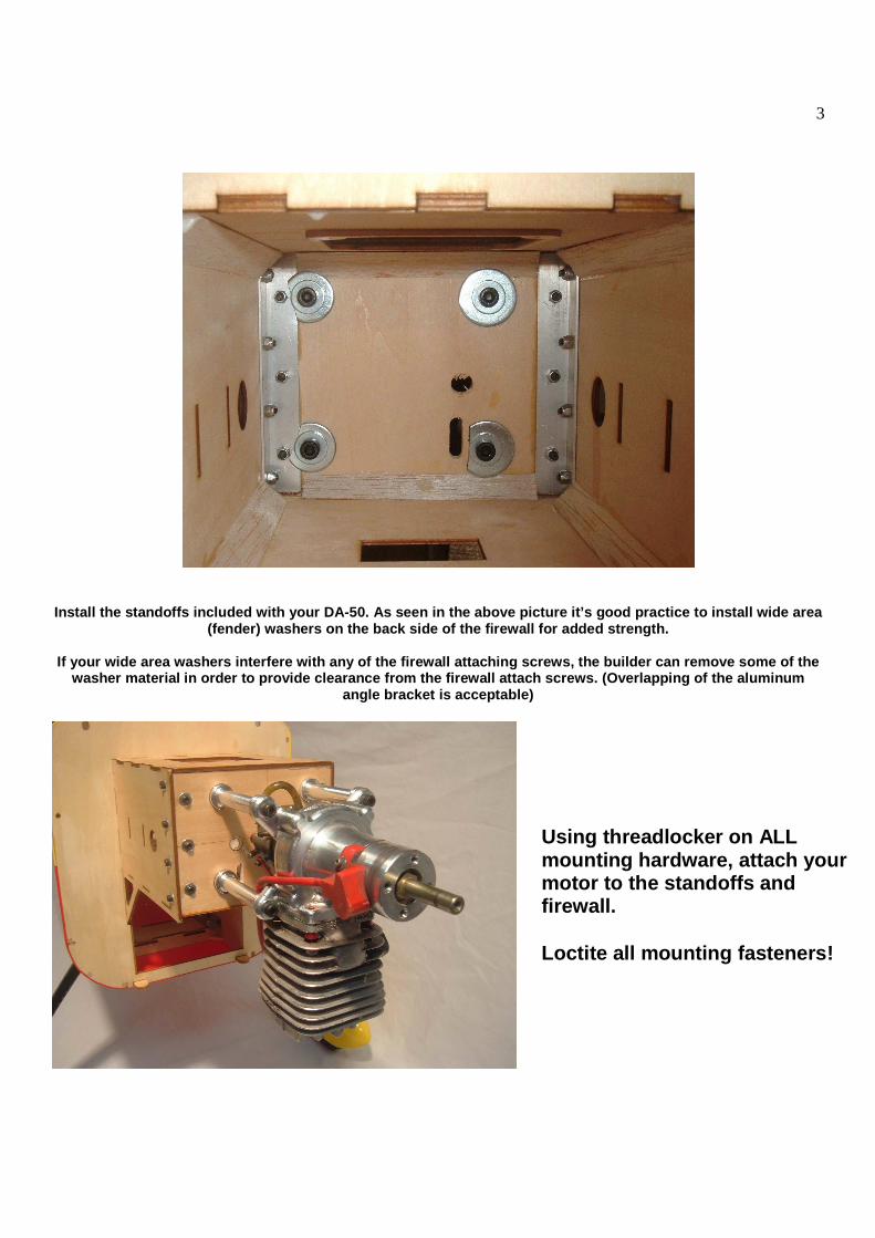
Install the standoffs included with your DA-50. As seen in the above picture it’s good practice to ins tall wide area (fender) washers on the back side of the firewall f or added strength.
If your wide area washers interfere with any of the firewall attaching screws, the builder can remove some of the
washer material in order to provide clearance from the firewall attach screws. (Overlapping of the alu minum angle bracket is acceptable)
Using threadlocker on ALL mounting hardware, attach your motor to the standoffs and firewall. Loctite all mounting fasteners!
4
Throttle and Choke:
You have several options for mounting your throttle servo. We have provided a location in the bottom of the engine-mounting box behind the firewa ll. This hole is cut for a full-size servo. We have also included two servo mounting boxes for full-size servos. These can be used to place throttle and choke servos anywhere you need w ithin the engine mounting box. Use good epoxy glue to attach these servo mounting boxes to the airframe. Note that if you use the throttle servo location i n the bottom of the engine box, you can use one of the servo boxes as a heat shield to protect the throttle servo from the exhaust header.
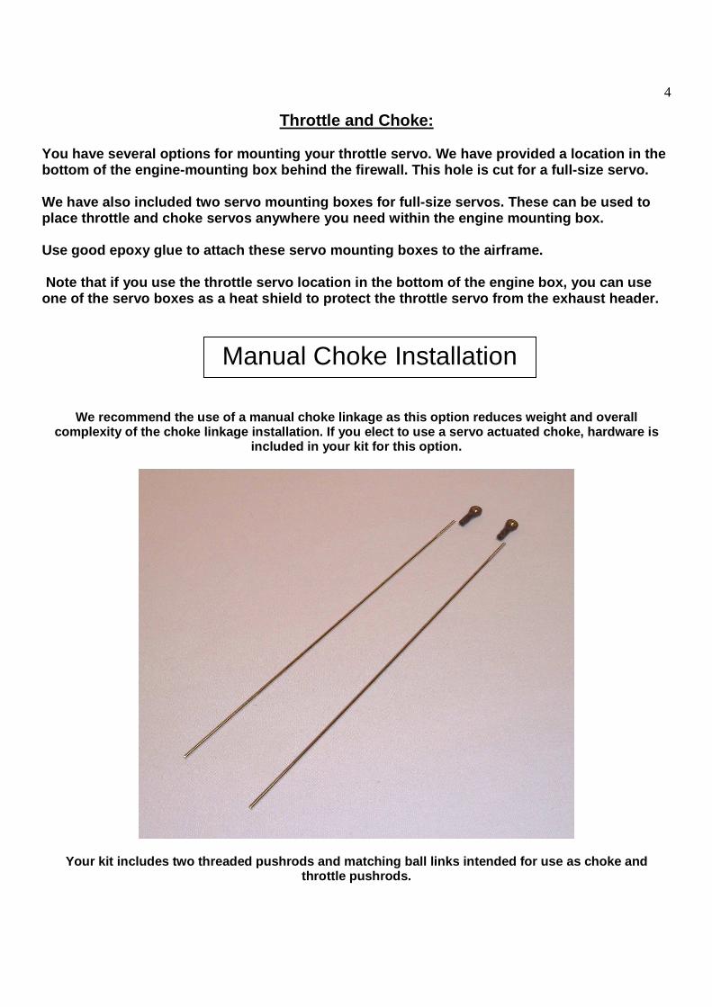
We recommend the use of a manual choke linkage as t his option reduces weight and overall complexity of the choke linkage installation. If yo u elect to use a servo actuated choke, hardware is
included in your kit for this option.
Your kit includes two threaded pushrods and matchin g ball links intended for use as choke and throttle pushrods.
Manual Choke Installation
5
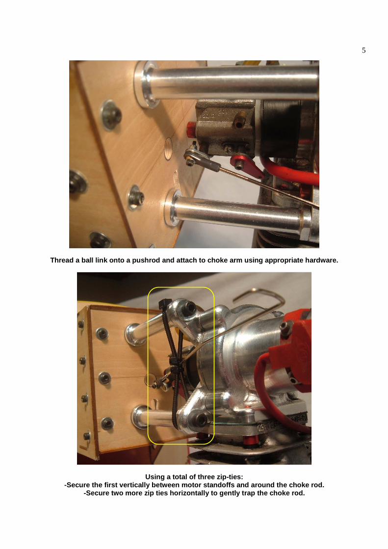
Thread a ball link onto a pushrod and attach to cho ke arm using appropriate hardware.
Using a total of three zip-ties: -Secure the first vertically between motor standoff s and around the choke rod.
-Secure two more zip ties horizontally to gently tr ap the choke rod.

6
Bend the choke rod to form a handle that can be acc essed just inside the fwd cowling vent.
Start by installing your preferred throttle servo a rm and thread ball link to throttle pushrod. Instal l one of the included “EZ-Connectors” to the servo arm as pictur ed above. Note: A DUBRO brand (or similar) solder-o n link
or rod end can be used in place of EZ-Connector if preferred.
Throttle Pushrod and Servo Installation
IMPORTANT: Be sure EZ-connector moves freely without binding. Apply a small drop of medium or thick CA glue to the nut. This step is necessary to prevent EZ-connector from working loose during operation.
7
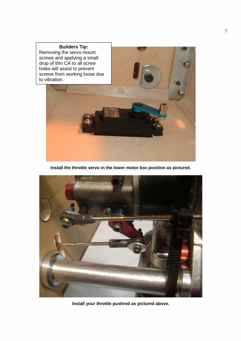
Install the throttle servo in the lower motor box p osition as pictured.
Install your throttle pushrod as pictured above.
Builders Tip: Removing the servo mount screws and applying a small drop of thin CA to all screw holes will assist to prevent screws from working loose due to vibration.
8
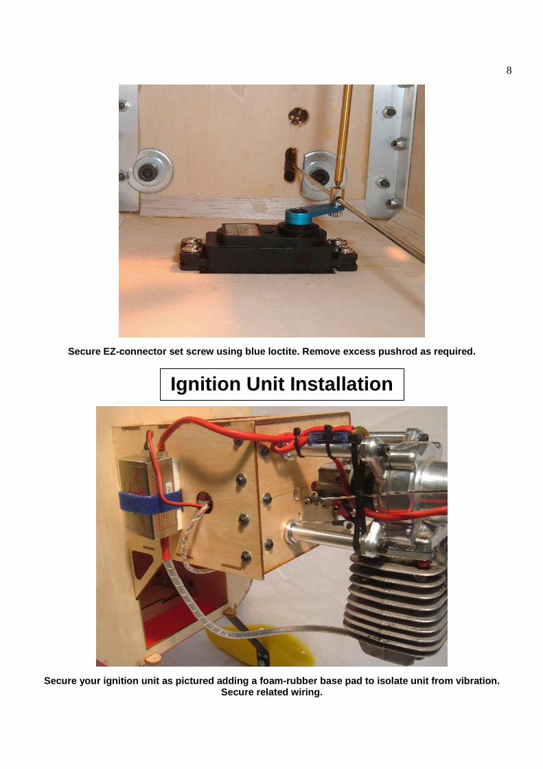
Secure EZ-connector set screw using blue loctite. R emove excess pushrod as required.
Secure your ignition unit as pictured adding a foam -rubber base pad to isolate unit from vibration. Secure related wiring.
Ignition Unit Installation
9
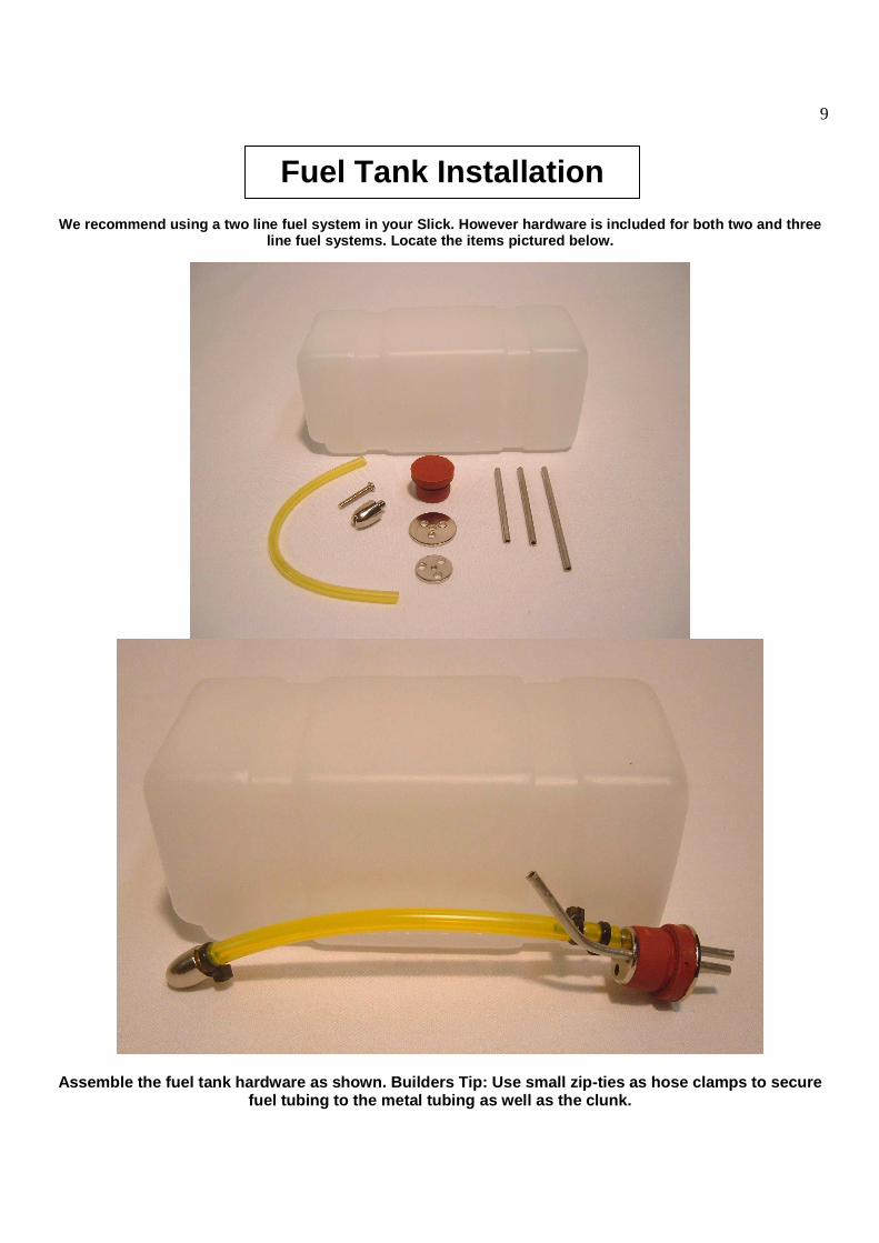
We recommend using a two line fuel system in your S lick. However hardware is included for both two and three line fuel systems. Locate the items pictured below.
Assemble the fuel tank hardware as shown. Builders Tip: Use small zip-ties as hose clamps to secure fuel tubing to the metal tubing as well as the clun k.
Fuel Tank Installation
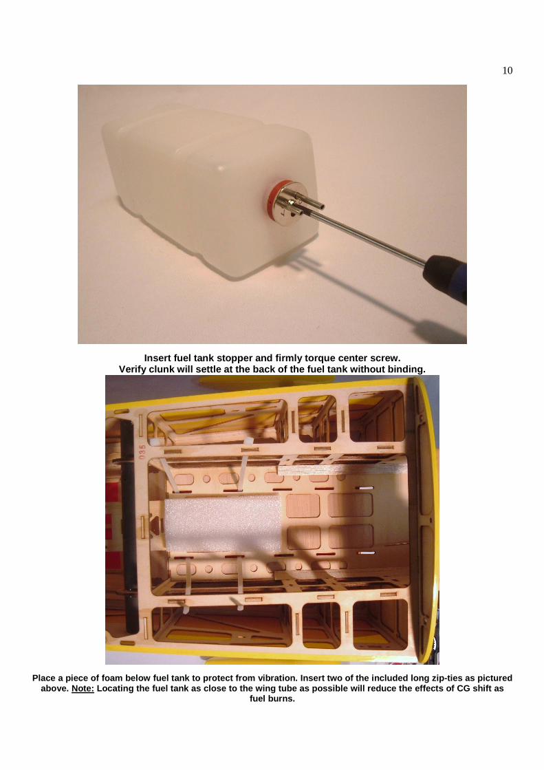
10
Insert fuel tank stopper and firmly torque center s crew. Verify clunk will settle at the back of the fuel ta nk without binding.
Place a piece of foam below fuel tank to protect fr om vibration. Insert two of the included long zip-t ies as pictured above. Note: Locating the fuel tank as close to the wing tube a s possible will reduce the effects of CG shift as
fuel burns.

11
Gently secure zip-ties around fuel tank. (Do not ti ghten all the way at this point)
Install the fuel vent line as pictured above again using small zip-ties to secure fuel line to the ven t tube. Run the vent line in a loop as pictured to prevent fuel loss during aerobatic maneuvers.
Firmly secure large zip-ties at this time.
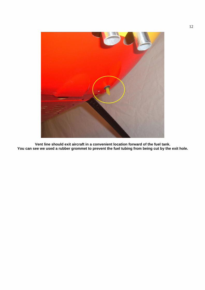
12
Vent line should exit aircraft in a convenient loca tion forward of the fuel tank. You can see we used a rubber grommet to prevent the fuel tubing from being cut by the exit hole.

13
Route the fuel line to the engine. You can use either a Du-Bro gasoline filler valve o r a fuel line T-connector and fuel dot.
The fuel line can be run through the front of the f irewall and to the carburetor.
Fuel-T
Fuel Dot
14
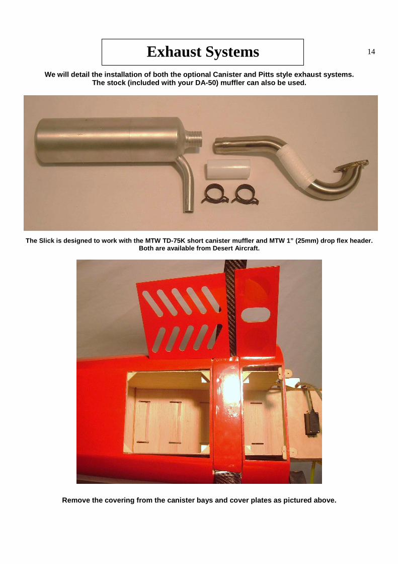
We will detail the installation of both the optiona l Canister and Pitts style exhaust systems.
The stock (included with your DA-50) muffler can al so be used.
The Slick is designed to work with the MTW TD-75K s hort canister muffler and MTW 1” (25mm) drop flex h eader. Both are available from Desert Aircraft.
Remove the covering from the canister bays and cove r plates as pictured above.
Exhaust Systems
15
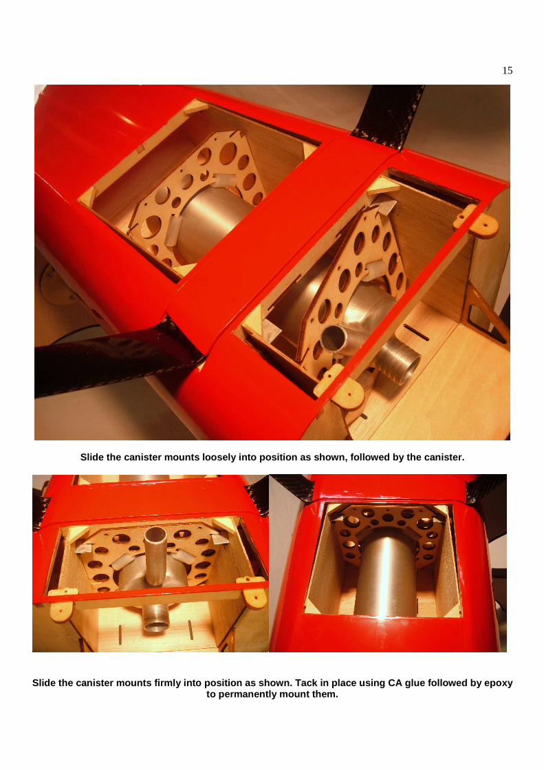
Slide the canister mounts loosely into position as shown, followed by the canister.
Slide the canister mounts firmly into position as s hown. Tack in place using CA glue followed by epoxy to permanently mount them.
16
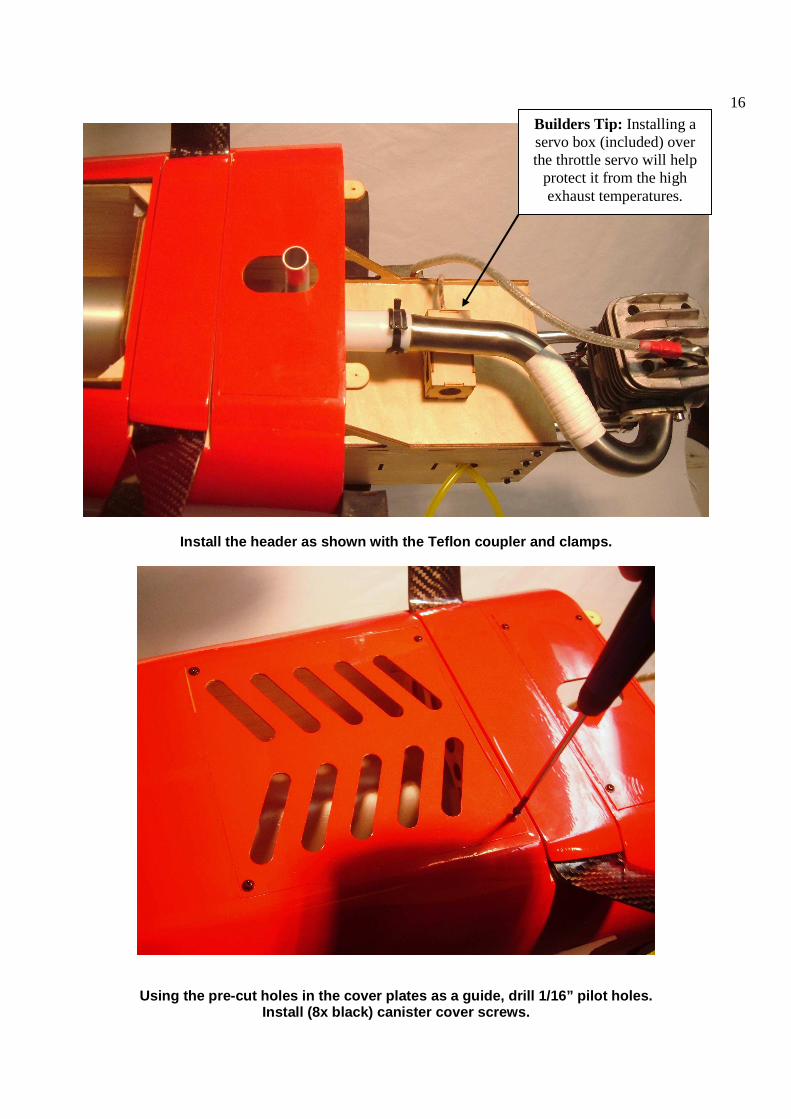
Install the header as shown with the Teflon coupler and clamps.
Using the pre-cut holes in the cover plates as a gu ide, drill 1/16” pilot holes. Install (8x black) canister cover screws.
Builders Tip: Installing a servo box (included) over the throttle servo will help
protect it from the high exhaust temperatures.
17
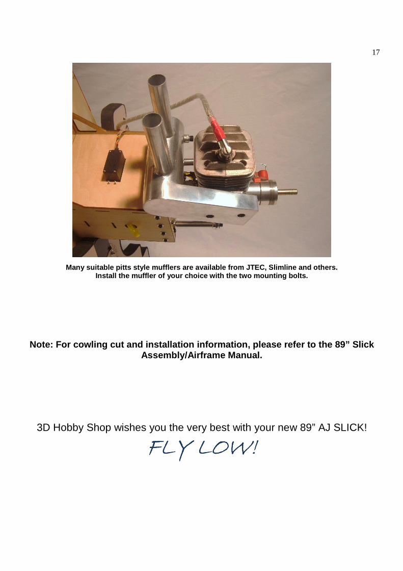
Many suitable pitts style mufflers are available fr om JTEC, Slimline and others. Install the muffler of your choice with the two mou nting bolts.
Note: For cowling cut and installation information, plea se refer to the 89” Slick Assembly/Airframe Manual.
3D Hobby Shop wishes you the very best with your new 89” AJ SLICK!
FLY LOW!FLY LOW!FLY LOW!FLY LOW!