notice: this bulletin is also applicable to kyle product ... · fault interrupters type ci;...
TRANSCRIPT

Figure 1.Type CI fault interrupter, 200 amp version.
December 1987 • New Issue
Fault InterruptersType CI; Three-PhaseMaintenance Instructions
1
87863KMA
S275-10-3Service Information
RADIATION WARNING:
Before performing electrical tests on Type CI fault inter-rupters, refer to Service Information S280-90-1, VacuumInterrupters Radiation Warning.
�
Serial No. 1000 and above
CONTENTSIntroduction . . . . . . . . . . . . . . . . . . . . . . . . . . . . . . . . . 1Description . . . . . . . . . . . . . . . . . . . . . . . . . . . . . . . . . 1Duty Cycle . . . . . . . . . . . . . . . . . . . . . . . . . . . . . . . . . . 2Maintenance . . . . . . . . . . . . . . . . . . . . . . . . . . . . . . . . 2
Frequency of Maintenance . . . . . . . . . . . . . . . . . . . . 2Periodic Maintenance Inspection . . . . . . . . . . . . . . . 2Insulation Level Withstand Tests . . . . . . . . . . . . . . . . 3
Shop Maintenance Procedures . . . . . . . . . . . . . . . . . 3Leak Testing Tank . . . . . . . . . . . . . . . . . . . . . . . . . . . 3Untanking . . . . . . . . . . . . . . . . . . . . . . . . . . . . . . . . . . 3Tanking . . . . . . . . . . . . . . . . . . . . . . . . . . . . . . . . . . . 5Interrupter Replacement . . . . . . . . . . . . . . . . . . . . . . 6Aperseal Cable Seals . . . . . . . . . . . . . . . . . . . . . . . . . . 6Electronic Trip Control . . . . . . . . . . . . . . . . . . . . . . . . 6
Testing CT Protectlon Board . . . . . . . . . . . . . . . . . . . 8Test Procedure . . . . . . . . . . . . . . . . . . . . . . . . . . . . . 8
Testing in Place . . . . . . . . . . . . . . . . . . . . . . . . . . . 8Bench Testing . . . . . . . . . . . . . . . . . . . . . . . . . . . . . 8
Operating Procedures . . . . . . . . . . . . . . . . . . . . . . . . 8Mechanical Operation Check . . . . . . . . . . . . . . . . . . . 8Electrical Operation Check . . . . . . . . . . . . . . . . . . . . 10Manual Closing . . . . . . . . . . . . . . . . . . . . . . . . . . . . . 10Manual Tripping . . . . . . . . . . . . . . . . . . . . . . . . . . . . . 10
In-Service Operation . . . . . . . . . . . . . . . . . . . . . . . . . . 10Initial Operation . . . . . . . . . . . . . . . . . . . . . . . . . . . . . 10Automatic Operation . . . . . . . . . . . . . . . . . . . . . . . . . 10
Schematic Diagrams . . . . . . . . . . . . . . . . . . . . . . . . . 10Service Parts List . . . . . . . . . . . . . . . . . . . . . . . . . . . . 12
the selected minimum-trip current value is exceeded, and after a timedelay, the control sends a trip signal to the interrupter operating mech-anism. Control operating power is also obtained from the BCT’s; thusno external power is required for timing or trip functions. The control iseasily programmed for various minimum trip values and time-currentcharacteristics on both phase and ground.
The integral galvanized-steel mounting frame with predrilled mount-ing holes facilitates wall, floor, or ceiling mounting. The electronic con-trol, enclosed in a weatherproof (nonsubmersible) cabinet and con-nected to the interrupter through two shielded plug-in cables, can bemounted on either side of the interrupter frame or at a remote locationup to 100 feet away.
High-voltage connections are made to either 200 amp universalbushing wells or 600 amp bushings depending on the continuous cur-rent rating of the unit selected. Both are molded as an integral part ofthe solid insulation system, and they interface with industry-standard200 amp loadbreak and nonloadbreak bushing plug inserts or 600amp shielded cable connectors.
INTRODUCTIONService Information S275-10-3 provides maintenance instruc-tions for the Type Cl three-phase fault interrupter. Included is ageneral description of the interrupter and control, and their oper-ation. A service parts list, keyed to exploded-view drawings ofthe interrupter, is included at the back of the manual.
DESCRIPTIONThe Type Cl fault interrupter (Figure 1) is an automatic, nonre-closing, three-phase interrupting device that will interrupt cur-rents through 12000 amps symmetrical on systems ratedthrough 38 kv. A compact, lightweight device, the Type Cl fea-tures submersible construction, a stored-energy mechanism,and dry, solid insulated vacuum interrupters.
Line currents are sensed by 1000:1 ratio encapsulated bush-ing current transformers on each phase on the interrupter. Thisprovides a continuous measurement of phase and ground cur-rent, which is monitored by the Electronic Trip Control. When
These instructions do not claim to cover all details or variations in the equipment, procedure, or process described, nor to provide direction formeeting every possible contingency during installation, operation, or maintenance. When additional information is desired to satisfy a problem notcovered sufficiently for the user’s purpose, please contact your Cooper Power Systems sales engineer.
NOTICE: This bulletin is also applicable to Kyle productserial numbers beginning with the prefix CP57.

2
Interrupter contact opening and closing is through release ofstored-spring energy. Both the opening and closing springs arecharged by a 120 volt ac motor which runs automaticallyimmediately after each opening operation. A push-pull springcharging feature permits manual spring charging should motorpower be lost.
In addition to automatic tripping on fault current, the Type Clinterrupter can be tripped with a remote contact, with the man-ual operated switch on the control panel, or with the mechani-cally-linked trip-reset lever, on the front of the mechanism tank.It can be closed with a remote contact, with the manual controlswitch on the panel, or with the mechanically-linked close leverat the front of the tank.
MAINTENANCEFrequency of MaintenanceBecause interrupters are applied under widely varying operat-ing and climatic conditions, maintenance intervals are bestdetermined by the user based on actual operating experience.To assure proper operation, interrupters must be maintainedwhen they have operated the equivalent of a complete dutycycle and before the dielectric strength has deteriorated belowprescribed levels. In the absence of specific operating experi-ence, the following procedures are recommended.
• When Type Cl interrupters are operated under usual serviceconditions as defined in ANSI (American National StandardsInstitute) C37.60,’`Requirements for overhead, PadMounted, Dry Vault, and Submersible Automatic CircuitReclosers and
DUTY CYCLE
CAUTIONNever use volatile solutions, detergents, or water-solublecleaners.
Percent of Number ofRated Max. Interrupter Minimum Unit
Voltage Rating X/R Operations
15-20 4 88
45-55 8 112
15.5kV 90-100 15 132
Total 232
15-20 3 88
27.0kV 45-55 7 112
90-100 14 32
Total 232
15-20 4 88
38.0kV 45-55 8 112
90-100 15 32
Total 232
Fault Interrupters for AC Systems,” it is recommended that thefollowing maintenance procedures must be performed yearly, orat the completion of an equivalent duty cycle.
• However, in the absence of specific operating experience, itis recommended that an external inspection be made on ayearly basis. (See “Maintenance Procedure” below.)
Periodic Maintenance InspectionEach periodic maintenance inspection, done at the completionof an equivalent duty cycle, should include:
1. Bypass and remove interrupter from service.2. Inspect external components.
A. Check for broken or cracked interrupters. Replace asnecessary.
B. Check for scratched paint, repaint as needed.C. Note counter reading and enter in the record log.
3. Perform an insulation level withstand test.4. Remove tank to expose internal components.5. Oil fills the cavity around the moving contact operator rod. If
oil or oil residue is observed within the tank, carefullyinspect the base of each interrupter to determine the sourceof the leak. If an interrupter is leaking, it should be returnedto the factory for repair.
6. Clean internal components.
Figure 2.Measuring erosion of interrupter contacts.
7. Check contact erosion of the vacuum interrupters. With thecontacts closed the dimension between the support plate andboss, see Figure 2, should not exceed 5/8".

S275-10-3
3
*May be limited by cables or terminations.
8. Check circuit components attached to the operatingmechanism.A. Check condition of wiring to terminal strips and
make sure all connections are tight.B. Check condition and operation of all microswitches
and trip solenoids.C. Check condition of current transformers and the
associated wiring, if equipped.9. Replace tank gasket. Apply quick-set adhesive to posi-
tion and hold gasket in groove at corners of tank.10. Check the tightness of all cable connectors and other
fastners.11. Clean gasket seat and retank the interrupter. Replace
the head bolts and tighten to 10-15 ft-lbs. torque. Applyclamping force gradually and equally, in rotation, toeach bolt to achieve an evenly distributed gasket seal-ing pressure. Leak test tank, see procedure page 3.
Insulation Level Withstand TestsHigh-potential withstand tests provide information on the di-electric condition of the interrupter. Testing is performed at75% of the rated low-frequency withstand voltage.
Interrupter Teat Voltage Test VoltageType BIL (Kv) (Kvac) (Kvdc)
15.5 Kv 95 26.3 4027 Kv 125 30 58.5*38 Kv 150* 45* 72*
WARNINGProper cable terminators must be used to attach test sup-ply to the interrupter bushing terminals. Use of impropercable terminators can result in flashovers, damage toequipment, serious personal injury or death.
TEST 1: Proceed as follows:1. Manually close interrupter.2. Ground tank and frame.3. Connect three upper bushings together.4. Apply proper test voltage to lower bushings.5. The interrupter should withstand the test voltage for 60
seconds.TEST 2: Proceed as follows:1. Manually close interrupter.2. Ground tank and frame.3. Ground Phase A and Phase C.4. Apply proper test voltage to Phase B.5. The interrupter should withstand the test voltage for 60
seconds.TEST 3: Proceed as follows:1. Manually open interrupter.
2. Ground tank and frame.3. Connect and ground three upper bushings.4. Connect three lower bushings.5. Apply proper test voltage to lower bushings.6. The interrupter should withstand the test voltage for 60
seconds.7. Reverse the connections: ground lower bushings; apply test
voltage to upper bushings for 60 seconds.8. The interrupter should withstand the test voltage for 60
seconds.TEST RESULTS: These high potential withstand tests provideinformation on the dielectric condition and integrity of the inter-rupters.
A. If the interrupter passes the closed-contacts test (Tests 1and 2) but fails the open-contacts test (Test 3),a deteriora-tion of one or more of the interrupters is likely to be thecause. Check each interrupter individually to determine thefailed phase or phases, and replace the interrupter(s).Retest to confirm the repair.
B. If the interrupter fails the closed-contacts tests (Test 1 and2) the cause is likely to be failed insulation. Replace dam-aged interrupter and retest.
SHOP MAINTENANCE PROCEDURESLeak Testing TankIf the interrupter is installed in an environment where it may besubmerged, it should be leak tested after the tank has beenremoved and replaced, to ensure that all seals are fluid tight.
CAUTIONDo not pressurize tank assembly to more than 5 psi. Pressuresbeyond 5 psi can cause permanent damage to the tank assem-bly and seals.
1. Remove plug, located on mechanism cover assembly.2. Attach a gas pressure source (nitrogen or clean dry air) to the
pressure fitting and slowly increase the pressure to between 4and 4-1/2, psi.
3. Apply liberal amounts of liquid soap solution to all seams, sealsand junctures. Leaks will be evidenced by expanding bubbles.If any leaks are observed, corrective measures must be taken.
NOTE: Pressure will escape through the control cable. As a result,thepressure source must be maintained throughout the leak testing.
4. Release pressure, disconnect gas pressure source, and rein-stall original plug with fresh sealing tape.
UntankingThe tank assembly is removable to allow access to the mecha-nism, and for vacuum interrupter removal. If access to the mecha-nism is required, the tank can be removed while the interrupterassembly remains in the frame assembly. However,
4
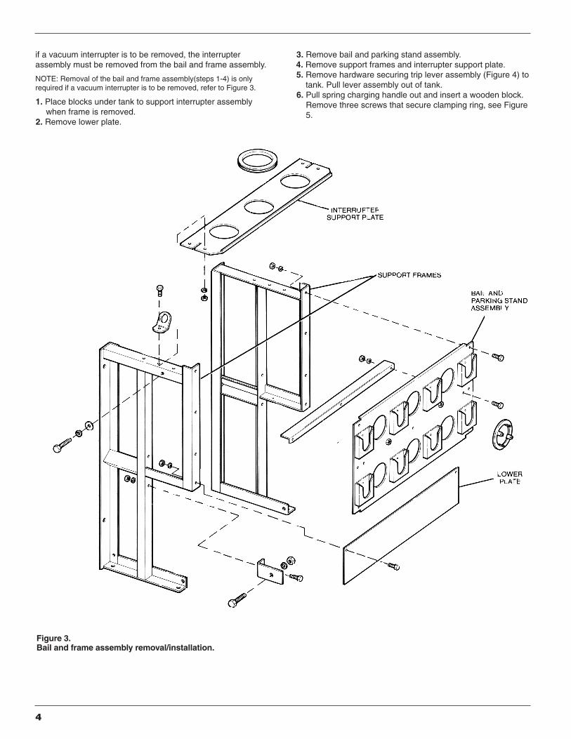
if a vacuum interrupter is to be removed, the interrupterassembly must be removed from the bail and frame assembly.
NOTE: Removal of the bail and frame assembly(steps 1-4) is onlyrequired if a vacuum interrupter is to be removed, refer to Figure 3.
1. Place blocks under tank to support interrupter assemblywhen frame is removed.
2. Remove lower plate.
3. Remove bail and parking stand assembly.4. Remove support frames and interrupter support plate.5. Remove hardware securing trip lever assembly (Figure 4) to
tank. Pull lever assembly out of tank.6. Pull spring charging handle out and insert a wooden block.
Remove three screws that secure clamping ring, see Figure5.
Figure 3.Bail and frame assembly removal/installation.

S275-10-1
5
Figure 4.Trip lever assembly removal/installation.
Figure 5.Clamping ring removal/installation.
Figure 6.Set screw removal.
Figure 7.Charging handle removal.
CAUTIONCarefully lift the mechanism assembly from tank. There isvery little clearance between the mechanism assemblyand the tank. If the mechanism binds or catches on thetank as it is removed, damage to the mechanism canresult.
CAUTIONCarefully lower the mechanism assembly into tank. There isvery little clearance between the mechanism assembly and thetank. If the mechanism binds or catches on the tank as it isremoved, damage to the mechanism can result.
WARNINGUse a suitable hoist when lifting interrupter assembly. If inter-rupter assembly only (without frame) is to be lifted, attach hooksto lifting points located between interrupters and secure sling tocenter interrupter. If the sling is not secured, the assembly willflip which could cause serious injury or damage to the equip-ment.
WARNINGUse a suitable hoist when lifting interrupter assembly. Ifinterrrupter assembly only (without frame) is to be lifted,attach hooks to lifting points located between interruptersand secure sling to center interrupter. If the sling is notsecured, the assembly will flip which could cause seriousinjury or damage to the equipment.
87887KMA 87891KMA
87890KMA87888KMA
7. Remove set screw, see Figure 6.8. Remove charging handle assembly, see Figure 7.
TankingTo retank interrupter proceed as follows:1. Clean the underside of the cover assembly to ensure a good
seal. Install a new tank seal, use quick-set adhesive to positionand secure gasket at corners of tank.
9. Remove hardware that secures cover assembly to tankand carefully lift assembly out of tank. Carefully guide themechanism assembly through tank opening.
6
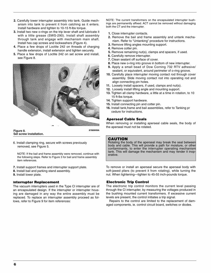
Figure 8.Set screw installation.
CAUTIONRotating the body of the aperseal may break the seal betweenbody and cable. This will provide a path for moisture, or othercontaminants, to enter the interrupter operating mechanismtank. This will damage the mechanism and may render it inop-erative.
87889KMA
2. Carefully lower interrupter assembly into tank. Guide mech-anism into tank to prevent it from catching as it enters.Install hardware and tighten to 10-15 ft-lbs torque.
3. Install two new o-rings on the trip lever shaft and lubricate itwith a little grease (SWS-290). Install shaft assemblythrough tank and engage with mechanism main shaft.Install hex cap screws and lockwashers (Figure 4).
4. Place a few drops of Loctite 242 on threads of charginghandle extension, install extension and tighten securely.
5. Place a few drops of Loctite 242 on set screw and install,see Figure 8.
6. Install clamping ring, secure with screws previouslyremoved, see Figure 5.
NOTE: If the bail and frame assembly were removed, continue withthe following steps. Refer to Figure 3 for bail and frame assemblyitem references.
7. Install support frames and interrupter support plate.8. Install bail and parking stand assembly. 9. Install lower plate.
Interrupter Replacement The vacuum interrupters used in the Type Cl interrupter are ofan encapsulated design. If the interrupter or interrupter hous-ing are damaged in any way the entire assembly must bereplaced. To replace an interrupter assembly proceed as fol-lows, refer to Figure 9 for item references:
NOTE: The current transformers on the encapsulated interrupter bush-ings are permanently affixed. ACT cannot be removed without damagingboth the CT and the interrupter.
1. Close interrupter contacts.2. Remove the bail and frame assembly and untank mecha-
nism. Refer to "Untanking” procedure for instructions.3. Remove lifting angles mounting support.4. Remove cotter pin.5. Remove remaining nut(s), clamps and spacers, if used.6. Carefully remove interrupter.7. Clean sealant off surface of cover.8. Place new o-ring into groove in bottom of new interrupter.9. Apply a small bead of Dow Corning 732 RTV adhesive/
sealant, or equivalent, around perimeter of o-ring groove.10. Carefully place interrupter moving contact rod through cover
assembly. Slide moving contact rod into operating rod andalign connecting pin holes.
11. Loosely install spacers, if used, clamps and nut(s).12. Loosely install lifting angle and mounting support.13. Tighten all clamp hardware, a little at a time in rotation, to 10
15 ft-lbs torque.14. Tighten support hardware.15. Install connecting pin and cotter pin.16. Install tank,frame and bail assemblies, refer to Tanking pr
cedure for instructions.
Aperseal Cable SealsWhen removing or installing aperseal cable seals, the body ofthe aperseal must not be rotated.
To remove or install an aperseal secure the aperseal body withsoft-jawed pliers (to prevent it from rotating), while turning thenut. When tightening—tighten to 45-55 inch-pounds torque.
Electronic Trip ControlThe electronic trip control monitors the current level passingthrough the Cl interrupter, by measuring the voltages produced inthe bushing mounted current transformers. If excessive currentlevels are present, the control initiates a trip signal.
Repairs to the control are limited to the replacement of dam-aged components, ie. control circuit board, switches or diodes.

S275-10-3
7
Figure 9.Interrupter replacement.

8
Figure 10.Testing CT protection circuit in place.
Figure 11.Bench testing CT protection circuit.
TESTING CT PROTECTION BOARDThe CT protection board provides automatic protection for thebushing mounted CTs. It is located within the mechanism tank,on the left side of the mechanism frame. When the control isremoved from an in-service interrupter, the CT protectionboard will automatically protect the CTs. If the CT protectionboard malfunctions, CT(s) can be damaged. The followingtests can be used to verify that the protection board is workingproperly.
Test circuits for the CT protection board are shown inFigures 10 and 11. The board can be tested without removalof either the mechanism tank or it may also be bench tested.
Test ProcedureTESTING IN PLACEAssemble and connect the equipment as shown in Figure 10,which shows the test current being applied to phase A.1. Manually close the interrupted contacts, refer to manual
closing procedure.2. Slowly increase the voltage on the variable transformer
while observing the voltage between pins A and D.3. After approximately 115 volts, the voltage should drop off
even though the voltage from the variable transformer isincreased. If the voltage does not drop off, the CT protec-tion board is not operating properly and must be replaced.
4. Disconnect input power and reconnect to test phase B andthen phase C. Ground can be tested between pins E & Fwhile the test circuit is connected to any phase.
BENCH TESTINGAssemble and connect the equipment as shown in Figure 11,which shows the test voltage being applied to phase A.1. Slowly increase the voltage on the variable transformer
while observing the voltage between the 1000:1 CT leads.2. After approximately 115 volts, the voltage should drop off
even though the voltage from the variable transformer isincreased. If the voltage does not drop off, the CT protectionboard is damaged and must be replaced.
3. Disconnect input power and reconnect to test phase B,phase C and ground.
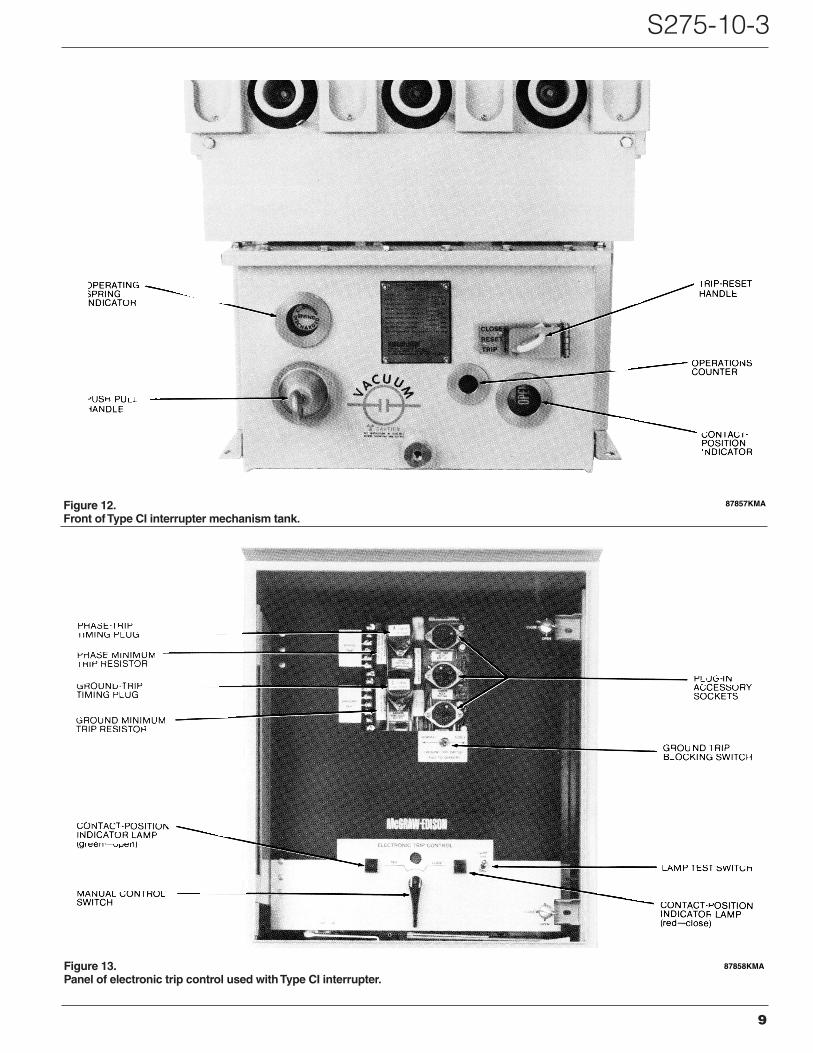
OPERATING PROCEDURESThe interrupter should not be operated or placed into serviceuntil there is a full understanding of its operating procedures.Mechanism and control levers and indicators referred to in thissection are identified in Figures 12 and 13.
Mechanical Operation CheckA simple nonelectric test of interrupter operation will assure thatthe operator mechanism and the interrupter linkage are func-tioning properly. The following procedure may be used.1. Remove control fuse from 120 volt ac fuse block in cabinet
interior to isolate mechanism from electrical system.2. Check that the interrupter is open. The Contact-Position
Indicator visible from the front of the mechanism tank shouldread OPEN.NOTE: If interrupter is closed move the Trip-Reset handle at thefront of the mechanism tank to TRIP. This will release a latch in themechanism and open the interrupter contacts. The Contact-PositionIndicator will then read OPEN.
3. Using the manual closing procedure described in ManualClosing section, close the interrupter. The Contact-PositionIndicator should read CLOSED.
4. Move the Trip-Reset handle to TRIP. The interrupter contactsshould open and the Contact-Position Indicators should readOPEN.
Successful completion of the above four steps confirm prop-er operation of the interrupter operating mechanism.
S275-10-3
9
Figure 13.Panel of electronic trip control used with Type CI interrupter.
Figure 12.Front of Type CI interrupter mechanism tank.
87857KMA
87858KMA

10
Electrical Operation CheckThe following procedure may be used to check the electricaloperation of the interrupter.1. Make sure that the Trip-Reset handle on the mechanism
tank is set on RESET.2. Apply 120 volt ac power. Upon application of power, the
spring-charging motor will run to charge the closingsprings. The spring-charging motor will stop running whenthe springs are fully charged and the spring indicator willindicate that the springs are charged.
3. To close the interrupter, move Manual Control switch oncontrol panel to CLOSE. The interrupter should closeimmediately. The red indicator lamp on the control panelshould light and the Contact-Position Indicator at the frontof the mechanism tank should read CLOSED.
4. To open the interrupter, move the Manual Control switch toTRIP. The interrupter should open. The green indicatorlamp on the control panel should light and the Contact-Position Indicator in the mechanism tank should readOPEN.
Manual ClosingManual deenergized closing into an energized line,without the120 volt ac supply, can be accomplished with the Push-Pullhandle located on the left front of the mechanism tank (Figure12).1. If the electronic control is connected, make sure the manual
control switch on the control panel has been moved to theTRIP position and released.
2. Move Trip-Reset handle, right front of mechanism tank toeither the TRIP or RESET position.
3. Pull Push-Pull handle approximately 30 times, or until theoperating spring indicator reads SPRING CHARGED.
4. Move Trip-Reset handle to CLOSE. Interrupter contacts willclose and handle will spring back to the RESET position.
Manual TrippingA closed interrupter can be manually tripped at the operatormechanism by moving the Trip-Reset handle at the front of thetank to TRIP.
This will release a trip latch in the operating mechanism,allowing the charged opening springs to drive the contacts totheir open position.
The interrupter cannot be closed while the Trip-Reset han-dle is in the TRIP position.
IN-SERVICE OPERATION
Initial OperationTo place the interrupter in operation, proceed as follows:1. Make sure that the control cables extending from the inter-
rupter are connected to the control and that 120 volt ac poweris supplied to the control.
2. Make sure that the Trip-Reset handle at the front of the inter-rupter mechanism tank is in the RESET position.
3. Move the Manual Control switch on the electronic controlpanel to CLOSE. The interrupter will close. The red indicatorlamp on the control panel will light and the indicator flag in themechanism will read CLOSED.
Automatic operationOnce the unit is closed and in service, the electronic control willautomatically trip the interrupter in accordance with the pro-grammed operating characteristics when a phase or ground faultoccurs. While closed, the red indicator lamp on the control panelwill provide a continuous indication of closed contacts. The indi-cator flag, visible through a viewing port at the front of the mech-anism tank, will display CLOSED.
To open the interrupter while it is in service, move the manualcontrol switch to TRIP. The interrupter will immediately open.Whether tripped automatically or manually, the green indicatorlamp on the panel and the OPEN position of the mechanism flagwill indicate open contacts.
If the remote control operating feature is being used, opera-tions initiated by the remote trip and close dry contacts will beidentical to those initiated with the Manual Control switch.Indicator lamp and Contact-Position Indicator displays will alsobe the same.
SCHEMATIC DIAGRAMSFigure 14 shows the schematic wiring diagrams for the Type Clinterrupter. This drawing reflects a standard unit. Refer to thewiring diagrams furnished with your interrupter for information onfactory installed accessories.

S275-10-3
11
Figure 14.Schematic diagram of Type CI interrupter.

12
SERVICE PARTS LISTThe service parts and hardware listed and illustrated includeonly those parts and assemblies usually furnished for repair orinvolved in the maintenance procedures described in this man-ual. Further breakdown of listed assemblies is not recommend-ed.
Dimensions of all common hardware parts have been care-fully checked so that they may be locally acquired. The suffixletter of the 14 character catalog number for common hard-ware parts codes the plating of the part:
A—No plating; raw materialH—SilverM—Black oxideQ—Cadmium + zinc + chromateY—Zinc + chromateZ—Electro zinc + bronze irriditeA hardware kit, Catalog No. KA849R1, contains an assort-
ment of roll pins, cotter pins, retaining rings, stop nuts, etc.—common hardware parts used in Cooper Power System's inter-rupters that may not be readily available locally.
To assure correct receipt of any parts order, always includeinterrupter type and serial number. Because of Cooper PowerSystem's continuous improvement policy, there may beinstances where the parts furnished may not look exactly thesame as the parts ordered. However, they will be completelyinterchangeable without any rework of the interrupter.
All parts carry the same warranty as any whole item ofswitchgear, i.e. against defects in material or workmanshipwithin a period of one year from date of shipment.
Catalog No. Description
KA1110ME Surge card assemblyKA852ME1 Heater assemblyKP4011A12 Silicon diode (D2)KP4012A44 Zener diode (D1)KPP140T Selector switch assembly (SW1)KP2069A8 Pointer knobKP2101A14 Terminal strip (T2)KP2101A214 Terminal marker (T2)KP1118ME Winq head studKP1119ME Stud retainer
Light socket Sylvania Cat. #30152-0Red lens, Sylvania Cat. #30170-0Green lens, Sylvania Cat. #30174-0Lamp, Sylvania Cat. #120 PSBToggle switch SW2)
KCF101EA Control circuit boardKP2056A5 Receptacle, 14 pin (R 1)KP2056A28 Receptacle, 10 pin (R2)KP2101A24 Terminal strip (T3)KP2101A224 Terminal marker (T3)KP1100ME Fuse block (F)KP1110ME Fuse block end pieceKP2075A13 FuseKCF51E* Time delay plug (phase)KCF51E* Time delay plug (ground)KCF110K* Minimum trip resistor (phase)KCF110K* Minimum trip resistor (ground)KCF53EA Phase instantaneous trip accessoryKCF53EB Phase and ground instantaneous trip accessoryKCF54EA Target accessoryKCF52EA Phase and ground inrush restraint accessoryKCF52EB Ground inrush restraint accessory
Type CI Interrupter Control Parts
Tank Assembly (Figure 15)
* Enter value or curve required
Item Catalog Ouan.No. DescrIptlon Number Req’d.
1 Retaining ring KP2013A41 12 Retaining ring KP2013A28 13 O-ring gasket KP2103A18 14 Tank assembly KNC1095A 15 Capscrew, hex hd,5/16-18 x 3/4,
st stl K730115131075A 226 Lockwasher, 5/16, med, st sti K900815031000A 227 Hex nut 5/16-18, st stl K880215118031A 228 Name plate KPP1026T1 19 Lock nuts KP2020A22 4
10 O-ring KP2000A56 111 Port cover assembly KNC142S00A 112 O-ring KP2000A34 113 Port cover assembly KP144VW54 214 Hinge and pointer assembly KNC175S 115 O-ring KP2000A26 216 Lockwasher, 1/4, med, st stl K900815025000A 217 Capscrew, hex hd,1/4-20 x 1/2,
st stl K730115125050A 218 Decal KP1041V4H 119 Charging handle KNC1186S 120 Hex jam nut 3/8-16 st stl K880715116038A 121 Shroud KNC1209S 122 Clamp KP2251A1 123 Screw round hd, #6-32 x 5/16
st sti K721515106031 A 324 Lockwasher, #6, st stl K900815006000A 325 Bellows KP2241 A 1 126 Clamping ring KNC 1208S 127 Shaft extension KNC1207S 128 Set screw KP2023A8 129 Guide plate KNC1206S 130 o-ring KP2006A56 131 Retaining ring KP2013A41 132 Spacer KP3009A208 133 Charging handle assembly KNC232S 134 Washer, 3/8, st stl K900215037000A 135 Capscrew, hex hd, 3/8-16x 1
st stl K732415137100A 1

S275-10-3
13
Figure 15.Tank assembly.

14
Figure 16.Bail and frame assembly.
S275-10-3
15
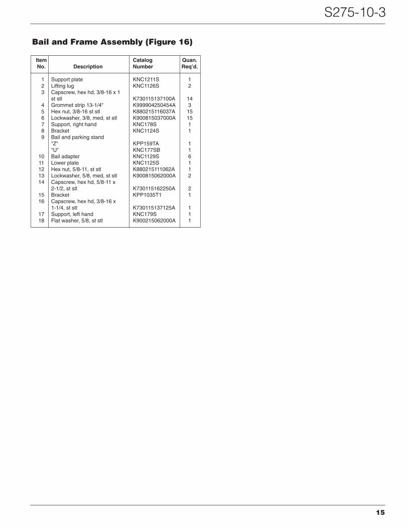
Bail and Frame Assembly (Figure 16)
Item Catalog Quan.No. Description Number Req’d.
1 Support plate KNC1211S 12 Lifting lug KNC1126S 23 Capscrew, hex hd, 3/8-16 x 1
st stl K730115137100A 144 Grommet strip 13-1/4" K999904250454A 35 Hex nut, 3/8-16 st stl K880215116037A 156 Lockwasher, 3/8, med, st stl K900815037000A 157 Support, right hand KNC178S 18 Bracket KNC1124S 19 Bail and parking stand
"Z" KPP159TA 1"U" KNC177SB 1
10 Bail adapter KNC1129S 611 Lower plate KNC1125S 112 Hex nut, 5/8-11, st stl K880215111062A 113 Lockwasher, 5/8, med, st stl K900815062000A 214 Capscrew, hex hd, 5/8-11 x
2-1/2, st stl K730115162250A 215 Bracket KPP1035T1 116 Capscrew, hex hd, 3/8-16 x
1-1/4, st stl K730115137125A 117 Support, left hand KNC179S 118 Flat washer, 5/8, st stl K900215062000A 1

Figure 17.Interrupter top cover assembly.
16

S275-10-3
17
Interrupter and Top Cover Assembly (Figure 17)
Item Catalog Quan.No. Description Number Req’d.
1 Hex nut,3/8-16, st stl K880215116037A 112 Lifting angle KNC1122S 23 Mounting support KNC1123S 14 Capscrew, hex hd, 1/4-20 x
5/8, st stl K730115125062A 35 Cable support KNC 1119S1 16 Lockwasher, 1/4, med, st stl K900815025000A 37 Hex nut, 1/4-20, st stl K880215120025A 38 Interrupter assembly Consult factory 39 Current transformer Consult factory 3
10 Cover assembly Consult factory 111 Spacer KP3011A27 212 Clamp KP1252VS 913 Cotter pin, 1/16 x 1 /2, brass K970525062050A 614 Connecting pin KNC1087S1 315 Capscrew, hex hd, 3/8-16 x
5/8, st stl K730115137062A 216 Lockwasher, 3/8, med, st stl K9W815037000A 217 Wire tie K994904170004A 418 O-ring KP2000A59 319 Aperseal KP2151A1 320 Pipe plug KP2007A10 1

18
Figure 18.Mechanism assembly.
S275-10-3
19
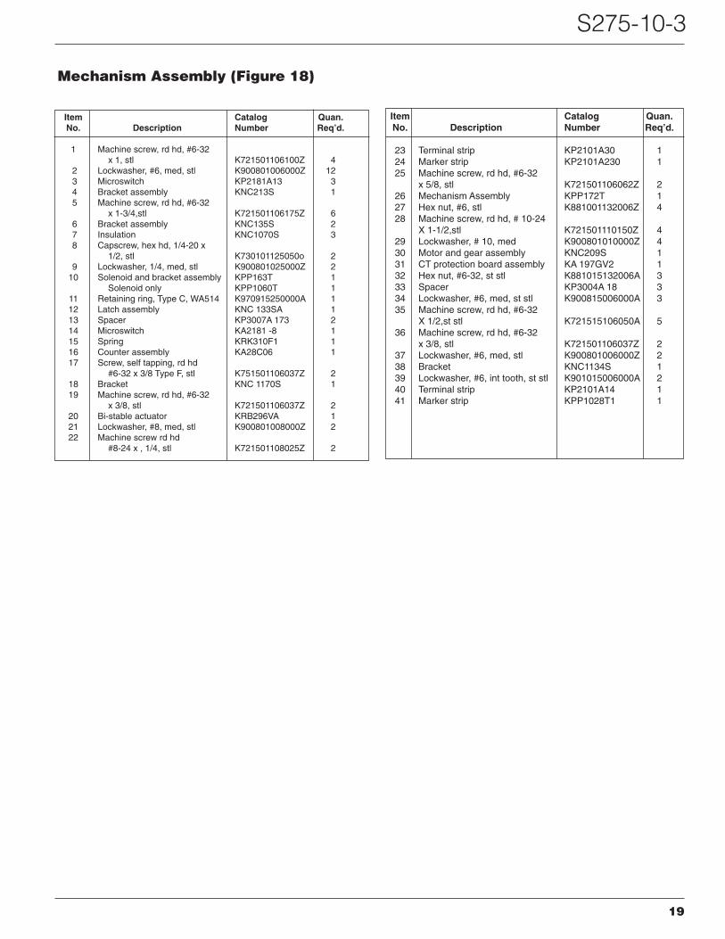
Mechanism Assembly (Figure 18)
Item Catalog Quan.No. Description Number Req’d.
1 Machine screw, rd hd, #6-32x 1, stl K721501106100Z 4
2 Lockwasher, #6, med, stl K900801006000Z 123 Microswitch KP2181A13 34 Bracket assembly KNC213S 15 Machine screw, rd hd, #6-32
x 1-3/4,stl K721501106175Z 66 Bracket assembly KNC135S 27 Insulation KNC1070S 38 Capscrew, hex hd, 1/4-20 x
1/2, stl K730101125050o 29 Lockwasher, 1/4, med, stl K900801025000Z 2
10 Solenoid and bracket assembly KPP163T 1Solenoid only KPP1060T 1
11 Retaining ring, Type C, WA514 K970915250000A 112 Latch assembly KNC 133SA 113 Spacer KP3007A 173 214 Microswitch KA2181 -8 115 Spring KRK310F1 116 Counter assembly KA28C06 117 Screw, self tapping, rd hd
#6-32 x 3/8 Type F, stl K751501106037Z 218 Bracket KNC 1170S 119 Machine screw, rd hd, #6-32
x 3/8, stl K721501106037Z 220 Bi-stable actuator KRB296VA 121 Lockwasher, #8, med, stl K900801008000Z 222 Machine screw rd hd
#8-24 x , 1/4, stl K721501108025Z 2
Item Catalog Quan.No. Description Number Req’d.
23 Terminal strip KP2101A30 124 Marker strip KP2101A230 125 Machine screw, rd hd, #6-32
x 5/8, stl K721501106062Z 226 Mechanism Assembly KPP172T 127 Hex nut, #6, stl K881001132006Z 428 Machine screw, rd hd, # 10-24
X 1-1/2,stl K721501110150Z 429 Lockwasher, # 10, med K900801010000Z 430 Motor and gear assembly KNC209S 131 CT protection board assembly KA 197GV2 132 Hex nut, #6-32, st stl K881015132006A 333 Spacer KP3004A 18 334 Lockwasher, #6, med, st stl K900815006000A 335 Machine screw, rd hd, #6-32
X 1/2,st stl K721515106050A 536 Machine screw, rd hd, #6-32
x 3/8, stl K721501106037Z 237 Lockwasher, #6, med, stl K900801006000Z 238 Bracket KNC1134S 139 Lockwasher, #6, int tooth, st stl K901015006000A 240 Terminal strip KP2101A14 141 Marker strip KPP1028T1 1

KDL6/05
1045 Hickory StreetPewaukee, WI 53072 USAwww.cooperpower.com©2005 Cooper Power Systems or its affiliates.